

Page 1

Installation Instructions
Original Instructions
Kinetix MPAI Heavy-duty Electric Cylinders
Catalog Numbers MPAI-A2xxxC, MPAI-B2xxxC, MPAI-A3xxxC, MPAI-B3xxxC, MPAI-A3xxxE, MPAI-B3xxxE, MPAI-A3xxxR, MPAI-B3xxxR, MPAI-A3xxxS,
MPAI-B3xxxS, MPAI-A4xxxC, MPAI-B4xxxC, MPAI-A4xxxE, MPAI-B4xxxE, MPAI-A4xxxR, MPAI-B4xxxR, MPAI-A4xxxS, MPAI-B4xxxS
Top ic Page
Summary of Changes 1
Catalog Number Explanation 2
About the Kinetix MPAI Heavy-duty Electric Cylinders 4
Before You Begin 4
Install the Electric Cylinder 6
Mount the Electric Cylinder 8
Dimensions 11
Connector Data 19
Commissioning 20
Maintenance 29
Troubleshoot Kinetix MPAI Electric Cylinders 32
Accessories 33
Specifications 37
Additional Resources 38
Summary of Changes
This publication contains new and updated information as indicated in the following table.
Top ic P age
Updated IP ratings information. 37
Page 2

Kinetix MPAI Heavy-duty Electric Cylinders Installation Instructions
MP AI - x x xxx x x x x x - x
Volta ge Cl ass
A = 200V
B = 400V
Actuator Type
AI = Actuator rod (threaded male rod end)
Actuator Series
MP = Kinetix MP
Actuator Mounting
A = Front face, side front, bottom front, and rear tapped mounting holes
B = Front trunnion, no tapped mounting holes
C = Rear clevis mount, no tapped mounting holes (food-grade paint only)
E = Front face mount, front face tapped mounting holes (food-grade paint only)
Holding Brake
2 = No brake
4 = 24V DC brake
Feedback Type
M = Multi-turn, 1024 sin/cos, absolute encoder, Hiperface protocol
(3)
V = Multi-turn, 128 sin/cos, absolute encoder, Hiperface protocol
Mechanical Drive/Screw Lead, Type
C = 5.0 mm/rev ball screw (0.197 in./rev)
E = 10.0 mm/rev ball screw (0.394 in./rev)
(3)
R = 5.0 mm/rev roller screw (0.197 in./rev)
(3)
S = 10.0 mm/rev roller screw (0.394 in./rev)
(3)
Rod Stroke Length
076 = 76.2 mm (3.0 in.)
(4)
150 = 152.4 mm (6.0 in.)
300 = 304.8 mm (12.0 in.)
450 = 457.2 mm (18.0 in.)
(3)
Actuator Frame Size
2 = 64 mm
3 = 83 mm
4 = 110 mm
5 = 144 mm
Special Feature
(1)
Blank = IP66/IP67 (in static condition only)
(2)
W = Food grade (white paint) stainless steel rod
Motor Type
1 = 076 mm (3.0 in.) stroke length
3 = 150…450 mm (6.0…18 in.) stroke lengths
Catalog Number Explanation
This is the catalog number explanation for the Kinetix® MPAI electric cylinders.
(1) The Special Feature field is used for customer-specific coding.
(2) Rockwell Automation® factory-delivered 2090-Series cable connectors are required to achieve this International Protection (IP) rating for the complete unit.
Maintain the front bearing and wiper seal at the prescribed interval. Wipe rods dry before motion occurs or liquid could be drawn inside the actuator.
(3) Not available in the 64 mm frame size.
(4) 76 mm stroke length is available in the 64 mm and 83 mm frame sizes only.
2 Rockwell Automation Publication MPAI-IN001G-EN-P - March 2021
Page 3

This is the catalog number explanation for the Kinetix MPAI electric cylinder accessories.
MP AI - xx x xx xx
Accessory Type
NA = Mounting accessory
NE = Rod-end accessory
NR = Replacement kit accessory
Actuator Type
AI = Actuator rod (threaded male rod end)
Actuator Series
MP = Kinetix MP
Actuator Frame Size
2 = 64 mm
3 = 83 mm
4 = 110 mm
5 = 144 mm
Option Number
01 = If NAx01, Front flange mount
If NRx01, Roller screw grease cartridge
If NEx01, Self-aligning rod coupler
21 = N Ax21, Front flange mount (stainless steel)
02 = If NAx02, Front flange mount
If NEx02, Anti-rotation option
If NRx02, Ball screw grease cartridge
03 = If NAx03, Rear clevis mount
If NEx03, Spherical rod-eye
If NRx03, Replacement zerk fitting
23 = NEx23, Spherical rod-eye (corrosion resistant)
04 = NEx04, Rod clevis
If NRx04, Grease plug
05 = Replacement zerk fitting cap
06 = NAx06, Mounting plates kit
If NRx06, Front wiper seal kit
07 = Front bearing block and wiper kit
Stroke Length
(1)
76 = 76.2 mm (3.0 in.)
15 = 152.4 mm (6.0 in.)
30 = 304.8 mm (12.0 in.)
45 = 457.2 mm (18.0 in.)
Kinetix MPAI Heavy-duty Electric Cylinders Installation Instructions
(1) The Stroke Length field is used for the anti-rotation guide only, catalog number MPAI-NEx02xx.
Rockwell Automation Publication MPAI-IN001G-EN-P - March 2021 3
Page 4
Kinetix MPAI Heavy-duty Electric Cylinders Installation Instructions
8
5
6
3
2
1
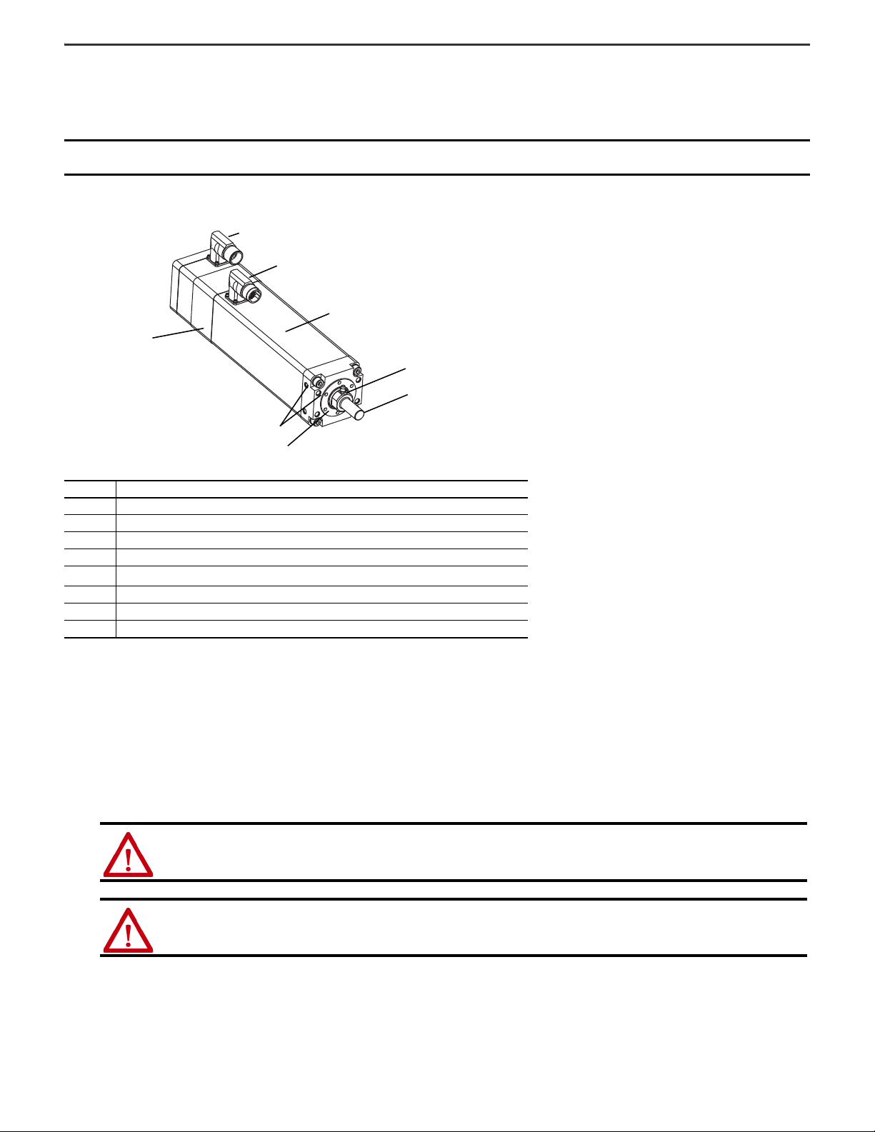
Kinetix MPAI Heavy-duty Electric Cylinder
(MPAI-A3150CM32A is shown)
4
7
About the Kinetix MPAI Heavy-duty Electric Cylinders
Kinetix MPAI electric cylinders feature multi-turn high-resolution encoders and are available with 24V DC brakes. The motor drives a ball-screw or roller-screw that converts
rotary motion into linear movement. The linear motion extends or retracts the thrust rod within the electric cylinder housing.
IMPORTANT
The MPAI-A/Bxxxxxx2x electric cylinders are non-braking. When there is no input torque, the thrust rod can be moved freely. To achieve self-
locking of your motion system, use an electric cylinder with an integrated brake (catalog number MPAI-A/Bxxxxxx4x).
The Kinetix MPAI electric cylinders have been designed for exact positioning at high speeds.
Item Description
1 Feedback connector
2Power connector
3 Motor with feedback device
4 Actuator cylinder
5
6 Wrench flats for counteracting torque on thrust rod when installing rod-end accessories
7 Grease fitting (not included on catalog number MPAI-x2xxxC)
8 Thrust rod
(1) Trunnion mount electric cylinders, not shown, have threaded mounting holes on the rear surface only.
Threaded mounting holes on front, sides, rear, and bottom surfaces
(1)
Before You Begin
Remove all packing materials from within and around the item. After unpacking, verify the nameplate catalog number against the purchase order.
1. Remove the polyethylene foam cushioning.
2. Remove the electric cylinder carefully from its shipping container.
Consider the weight of the electric cylinder. Depending on the design, the electric cylinder can weigh up to 49 kg (108 lb).s
Do not rotate the thrust rod. Rotating the thrust rod causes the home position to be lost.
ATTENTION: Electric cylinders that exceed 23 kg (51 lb) require a two man lift. Do not lift the electric cylinder by the thrust rod.
ATTENTION: Do not rotate the thrust rod. Rotating the thrust rod causes the factory-set home position to be lost and requires the electric
cylinder to be homed before its initial use.
3. Visually inspect the electric cylinder for damage.
Closely examine the mounting surface, frame, and thrust rod for defects.
4 Rockwell Automation Publication MPAI-IN001G-EN-P - March 2021
Page 5

Kinetix MPAI Heavy-duty Electric Cylinders Installation Instructions
4. Notify the carrier of shipping damage immediately.
ATTENTION: Do not attempt to open and modify the electric cylinder beyond changing motor connector orientation as described on page 10,
or installing a rear clevis mount as described on page 8. Only a qualified Allen-Bradley® employee can service the internal working of the
electric cylinder.
Failure to observe these safety precautions could result in personal injury or damage to equipment.
Plan Your Installation
See the Kinetix Linear Motion Specifications Technical Data, publication KNX-TD002, for the specifications and additional products referenced in this section:
• This product can be operated in compliance with the relevant safety regulations, only if the maximum loading limits are observed.
ATTENTION: The electric cylinder is not intended to be used in applications where side-loading occurs. Loads must be guided and supported.
Aligned load with the line-of-motion of the thrust rod. Side loading reduces the lifetime of the electric cylinder.
• If you are mounting your electric cylinder in a vertical or sloping position, include safety measures that control the work load, in case the spindle nut fail.
ATTENTION: Uncontrolled moving masses can cause injury or damage to property. If there is a spindle nut fracture inside the actuator
cylinder due to wear, the working mass drops down. Check whether additional external safety measures are required to prevent damage in
the event of a spindle nut fracture.
• Keep the rod from rotating when in use to achieve consistent linear motion. In most applications the connection to the load inherently provides anti-rotation. If your
work load is free to rotate when the actuator is attached use the anti-rotate option, catalog MPAI-NEx02xx, to prevent rotation.
• Corrosive environments reduce the service life of electric cylinders.
• Where possible, install the electric cylinder with the grease fitting facing up. This reduces the chance of the residual grease falling or dripping on your application.
• Factory-manufactured feedback and power cables are available in standard cable lengths. They provide environmental sealing and shield termination. Contact your
Allen-Bradley sales office or see the Kinetix Linear Motion Specifications Technical Data, publication KNX-TD002
, for additional information.
Prolong Electric Cylinder Life
Thoughtful design and proper maintenance can increase the life of an electric cylinder. Follow these guidelines to maximize the life of an electric cylinder especially within
a food processing environment:
• Always provide a drip loop in each cable to carry liquids away from the connection to the motor.
• If design requirements permit, provide shields that protect the motor housing, thrust rod, seals, and their junctions from contamination by foreign matter or fluids.
• Replace the thrust rod seals at or before its expected lifetime of 12-months.
See Replacement Parts and Maintenance Kits
• Inspect the seals for damage or wear on a regular basis. If damage or excessive wear is observed, replace the item.
on page 36 for catalog information on thrust rod seals.
Electric Cylinders with Brake Option
The brake option on this servo motor is a spring-set holding brake that releases when voltage is applied to the brake coil. A separate power source is required to disengage
the brake. This power source can be applied by a servo motor controller or manual operator control.
If system main power fails, holding brakes can withstand occasional use as stopping brakes. However, this creates rotational mechanical backlash that is potentially
damaging to the system, increases brake wear, and reduces brake life.
An electric cylinder (not under power) requires a holding brake to maintain its position if the force on the actuator exceeds the Back Drive Force listed in Kinetix Linear
Motion Specifications Technical Data, publication KNX-TD002.
A brake can be used with the actuator to keep it from back driving, typically in vertical-load applications. A brake can be used for safety reasons or for energy savings
allowing the actuator to hold position when not under power.
IMPORTANT
Holding brakes are not designed to stop rotation of the motor shaft, nor are they intended to be used as a safety device. They are designed to hold
a motor shaft at 0 rpm for up to the rated brake holding torque.
The recommended method of preventing motor shaft rotation is a four-step process: first, command the servo drive to 0 rpm; second, verify the
motor is at 0 rpm; third, engage the brake; and fourth, disable the drive.
Disabling the drive removes the potential for brake wear caused by a badly-tuned servo system oscillating the shaft.
Rockwell Automation Publication MPAI-IN001G-EN-P - March 2021 5
Page 6

Kinetix MPAI Heavy-duty Electric Cylinders Installation Instructions
Prevent Electrical Noise
Electromagnetic interference (EMI), commonly called electrical noise, can reduce motor performance. Effective techniques to counter EMI include filtering the AC power, by
using shielded cables, separating signal cables from power wiring, and practicing good grounding techniques.
Follow these guidelines to avoid the effects of EMI:
• Isolate the power transformers or install line filters on all AC input power lines.
• Physically separate signal cables from motor cabling and power wiring. Do not route signal cables with motor and power wires, or over the vent openings of servo
drives.
• Ground all equipment by using a single-point parallel ground system that employs ground bus bars or large straps. If necessary, use additional electrical noise
reduction techniques to reduce EMI in noisy environments.
See System Design for Control of Electrical Noise Reference Manual, publication GMC-RM001
, for additional information on reducing the effects of EMI.
Build and Route Cables
Knowledgeable cable routing and careful cable construction improves system electromagnetic compatibility (EMC).
To build and install cables, perform these steps.
1. Keep wire lengths as short as physically possible.
2. Route signal cables (encoder or serial) away from motor and power wiring.
3. Separate cables by 0.3 m (1 ft) minimum for every 9 m (30 ft) of parallel run.
4. Ground both ends of the encoder cable shield and twist the signal wire pairs to prevent electromagnetic interference (EMI) from other equipment.
ATTENTION: High voltage can be present on the shield of a power cable, if the shield is not grounded.
Make sure there is a connection to ground for any power cable shield.
Failure to observe these safety precautions could result in personal injury or damage to equipment.
Install the Electric Cylinder
The installation must comply with all local regulations and use of equipment and installation practices that promote electromagnetic compatibility and safety.
ATTENTION: Unmounted electric cylinders, disconnected mechanical couplings, and disconnected cables are dangerous if power is applied.
Appropriately identify (tag-out) disassembled equipment, and restrict (lock-out) access to electrical power.
Failure to observe these safety precautions could result in personal injury.
Follow these steps to prepare the electric cylinder for installation on the machine.
1. Provide sufficient clearances in the area of the electric cylinder for it to stay within its specified operating temperature range.
See Specifications
cooling. Keep other heat producing devices away from the electric cylinder.
2. Make sure the mounting surface supports the electric cylinder evenly so that it is free of mechanical stress and distortion.
• Evenness of the mounting surface must be within 0.127 mm (0.005 in.).
• The thrust rod must be parallel to the guide within 0.0254 mm (0.010 in.).
3. Attach mounting accessories to the electric cylinder.
See Accessories
6 Rockwell Automation Publication MPAI-IN001G-EN-P - March 2021
on page 37 for the operating temperature range. Do not enclose the electric cylinder unless forced air is blown across the electric cylinder for
on page 33 for the accessories diagram.
ATTENTION: Proper attachment of the rear clevis mount is important to achieve an IP67 rating in a stationary condition. See Install the Rear
Clevis Mounting Kit on page 8.
Failure to observe precautionary steps could result in damage to the electric cylinder and its components.
Page 7
Use these torque values to attach mounting accessories to the cylinder.
Wrench
Flats
Kinetix MPAI Heavy-duty Electric Cylinders Installation Instructions
Frame Size Mounting Plates Front Flange
64 MPAI-NA206 MPAI-NA202 MPAI-NA203 13.2 N•m (117 lb•in)
83 MPAI-NA306 MPAI-NA302 MPAI-NA303
110 MPAI-NA406 MPAI-NA402 MPAI-NA403
144 MPAI-NA506 MPAI-NA502 MPAI-NA503 56.5 N•m (41.7 lb•ft)
(1) Rear clevis requires removal of the end cap from the electric cylinder. If the cylinder is opened, take precautions to avoid contamination and then reseal the cylinder so an IP67 in a static condition is
achieved.
(2) Unless otherwise noted, torque specifications have a ±20% tolerance.
(3) The anti-rotation guide is not included in this step. See step 6 below for the anti-rotation guide torque values.
Rear Clevis
(1)
Torque, ma x
39.5 N•m (29.1 lb•ft)
(2) (3)
If desired, you can seal the actuator front flange to the drive equipment by applying a bead of food grade RTV around the periphery of the joint between the
actuator and the machine surface. Use of a gasket or RTV on the mating surface is not recommended, as this can cause the misalignment of the shaft and result in
damage to the actuator and the driven equipment.
4. Attach rod-end accessories to the work load as outlined below.
See Accessories
on page 33 for the accessories diagram. Be sure the work load center of gravity is centric to the thrust rod.
ATTENTION: Damage can occur to the electric cylinder bearings and the feedback device if sharp impact to the thrust rod is applied during
installation. Do not strike the thrust rod with tools during installation or removal.
Failure to observe these safety precautions could result in damage to the electric cylinder and its components.
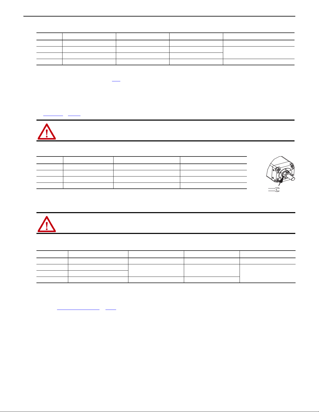
5. Use these torque values to attach a rod eye or rod clevis to the thrust rod.
Frame Size Thrust Rod Thread Wrench Flats Width
64 M10 x 1.25 22.99 mm (0.905 in.) 24.4 N•m (18.0 lb•ft)
83 M16 x 1.5 26.97 mm (1.062 in.) 61.0 N•m (45.0 lb•ft)
110 M20 x 1.5 38.08 mm (1.489 in.) 76.3 N•m (56.3 lb•ft)
114 M27 x 2.0 53.98 mm (2.125 in.) 135.6 N•m (100.0 lb•ft)
(1) Unless otherwise noted, torque specifications have a ±20% tolerance.
Tor que , max
(1)
Use two wrenches to attach a rod-end accessory: one wrench to tighten the rod-end accessory, and the other wrench to counter act the applied torque at the
thrust-rod wrench flats.
ATTENTION: Do not apply torque or rotate the thrust rod itself. Rotating the thrust rod causes the home position to be lost.
6. Use these torque values to attach an anti-rotation guide to the cylinder and the thrust rod.
Frame Size Cat. No.
64 MPAI-NE202xx 13.2 N•m (117 lb•in) 7.8 N•m (69 lb•in) 7.8 N•m (69 lb•in)
83 MPAI-NE302xx
144 MPAI-NE502xx 56.5 N•m (70.0 lb•ft) 20.3 N•m (15.0 lb•ft)
(1) Torque value applies to mounting screws with standard threads and strength class 8.8. Apply torque to mounting screws evenly.
(2) Torque value applies to the clamp bolt attached to the thrust rod of the electric cylinder.
(3) Torque value applies to the clamp bolt attached to the horizontal guide shaft of the Anti-rotation guide.
Bearing Block Screws
39.5 N•m (29.13 lb•ft) 7.8 N•m (5.75 lb•ft)
(1)
Thrust Rod Clamp
(2)
Anti-rotation Shaft
13.2 N•m (9.74 lb•ft)110 MPAI-NE4 02xx
To reduce wear on the horizontal guides of the Anti-rotation kit, adjust the guides at the work load and the electric cylinder so that they are exactly parallel, as
described in Mount the Electric Cylinder
on page 8.
(3)
Rockwell Automation Publication MPAI-IN001G-EN-P - March 2021 7
Page 8
Kinetix MPAI Heavy-duty Electric Cylinders Installation Instructions
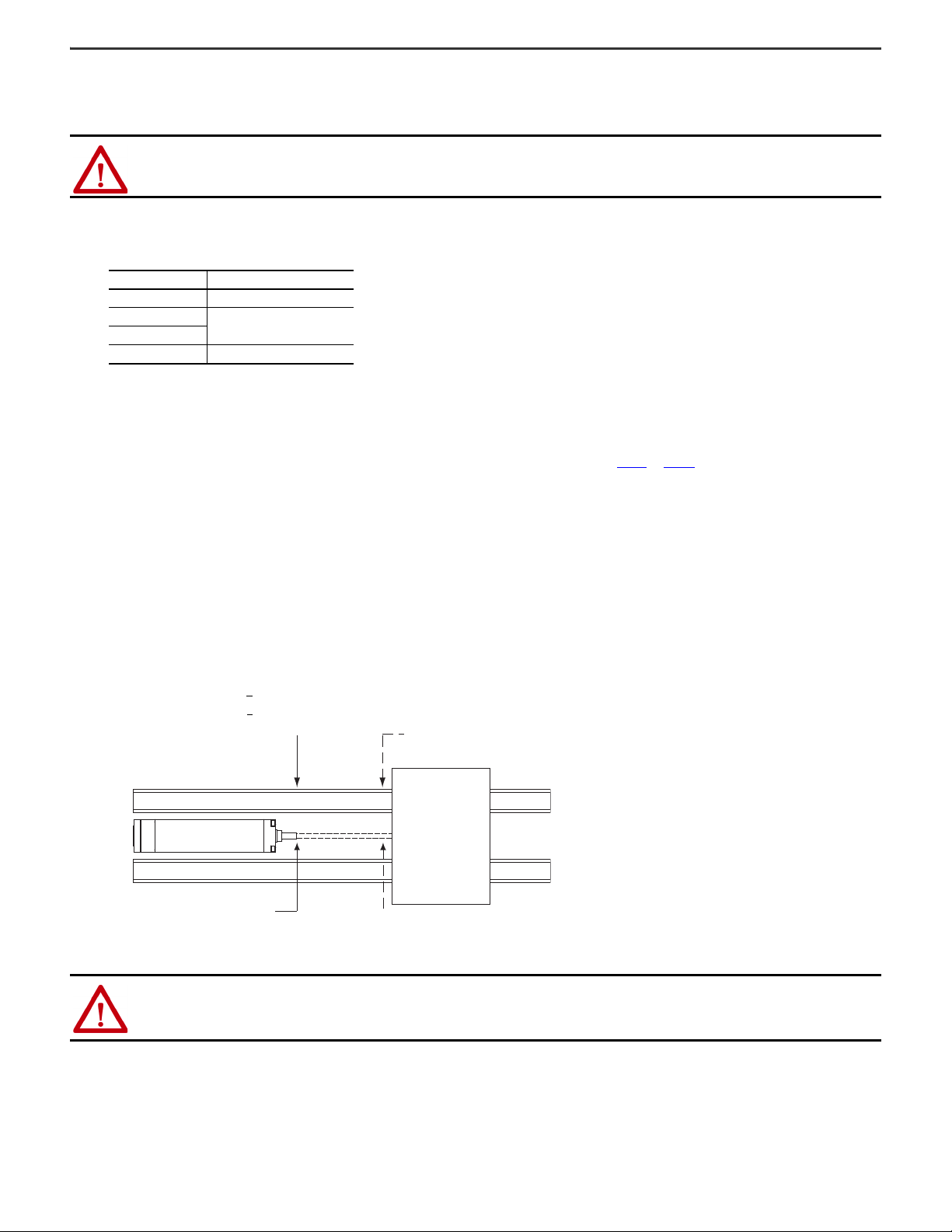
Load
Rod Extended
< 0.254 mm (0.010 in.)
Rod Retracted
< 0.127 mm (0.005 in.)
Load
Guide
Guide
Thrust Rod
Electric Cylinder
Install the Rear Clevis Mounting Kit
Follow this procedure to install a rear clevis mount on an Kinetix MPAI electric cylinder.
ATTENTION: Proper attachment of the rear clevis mount is important to achieving an IP67 in a static condition. Failure to observe this procedure
could result in damage to the electric cylinder and its components.
1. Prepare a contamination-free area in which to work.
2. Remove the four bolts that secure the end cap.
Bolts sizes are shown here.
Frame Size Bolt Size
64 M6 x 1.0 (0.04)
83
110
144 M12 x 1.75 (0.07)
3. Set aside the mounting bolts for reuse.
4. Clean the mounting surface and verify it is undamaged before continuing.
5. Carefully position the rear clevis mount and seal on the mounting surface.
The seal is included in the rear clevis mounting kit.
6. By using an alternating torque pattern, evenly torque each of the four mounting bolts to the value shown in step 5
M8 x 1.25 (0.05)
on page 7.
Mount the Electric Cylinder
Follow these steps to mount the electric cylinder on the machine.
1. Verify the mounting surface flatness.
The mounting surface must be flat or shimmed flat to the mounting surface of the electric cylinder within 0.127 mm (0.005 in.) to avoid distortion and damage to the
actuator housing.
2. Install and evenly tighten the steel fasteners so the electric cylinder is securely mounted on the machine before thrust rod alignment is performed.
3. Align the electric cylinder as shown in the diagram and described below.
Align the thrust rod of the electric cylinder parallel to the load supporting bearing system in both flatness and straightness within these specifications:
• With thrust rod extended <
• With thrust rod retracted <
4. Torque the steel fasteners evenly to 39.5 N•m (350 lb•in), and then verify the thrust rod alignment remains within specifications.
0.254 mm (0.010 in.) parallel to the load guides.
0.127 mm (0.005 in.) parallel to the load guides.
ATTENTION: When installed, pinch points with high forces are created that have the potential for causing physical damage. The risk area surrounding
the electric cylinder must be enclosed or clearly marked, including sinage in accordance with national and international requirements.
The risk area must be protected by a safety system that stops the equipment if anyone enters the risk area. Personnel who enter the risk area must be
authorized, trained, and qualified for any task performed inside the risk area.
8 Rockwell Automation Publication MPAI-IN001G-EN-P - March 2021
Page 9
Kinetix MPAI Heavy-duty Electric Cylinders Installation Instructions
O-ring
Groove reserved for
quick-lock plug.
Backshell Seal Inside
Feedback and Power/
Brake Connector
Housing
Flat Surface
with Logo on Top
Top of connector is relative to
motor orientation.
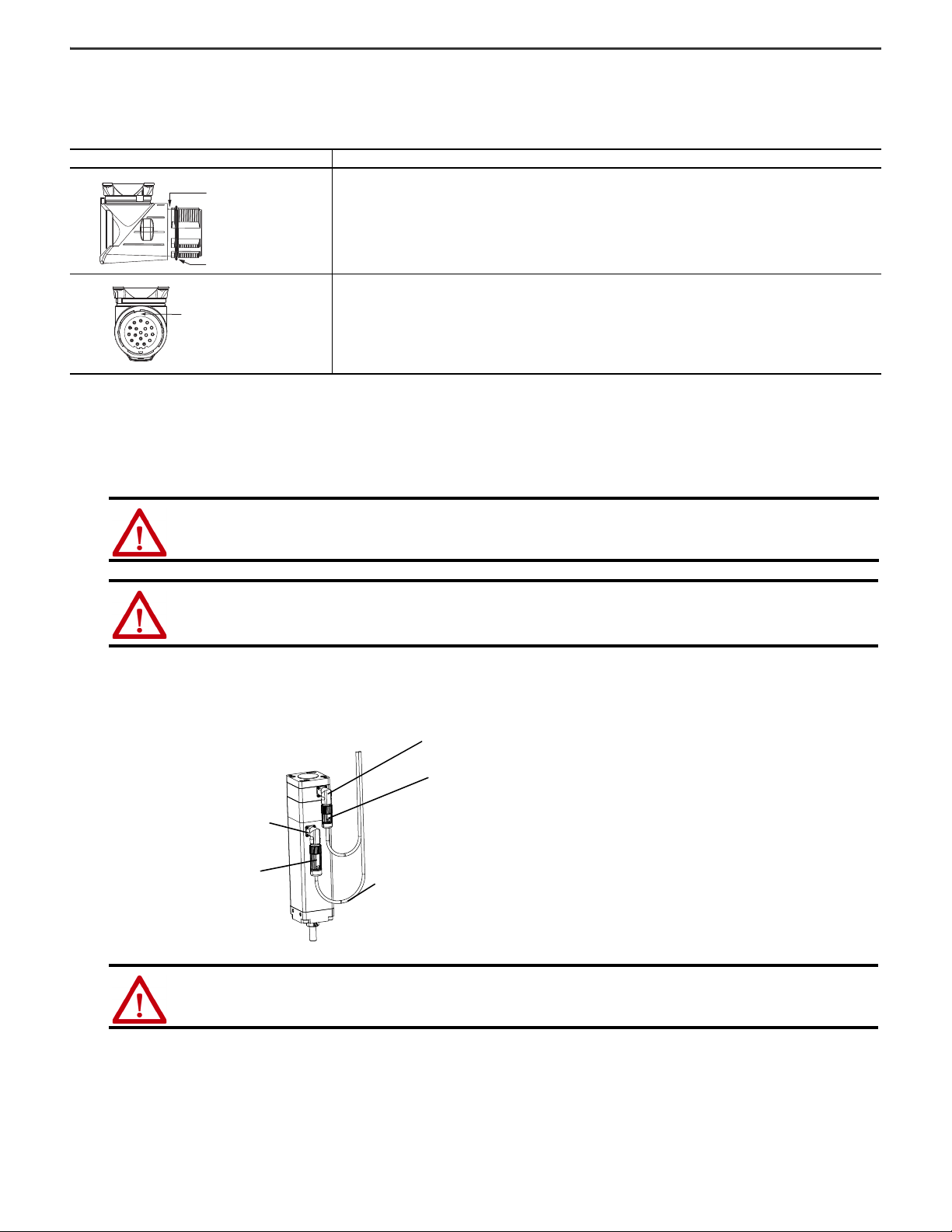
Feedback Connector
Drip Loop
Power Connector
Flat Surface
with Logo on Top
Verify Connector O-ring and Back-shell Seal
An O-ring on the feedback connector, and a back-shell seal on the feedback and power/brake connectors are necessary to achieve the maximum environmental rating.
Verify the seal and O-rings are installed as described.
Location Verify
• An O-ring is mounted on the external surface of the feedback connector and the power/brake connector.
• The O-ring is undamaged, not twisted, and rests in the groove near the rear of the connector.
• A back-shell seal covers the joint inside the feedback and power/brake housings. It seals the joint between the back-shell and
the housing of the connector.
• The back-shell seal is undamaged, and it is fully seated against the face of the back-shell.
Attach Motor Cables
Use this procedure to attach the power and feedback cables after the electric cylinder is mounted.
1. Carefully align each cable connector with the respective motor connector as shown in the diagram.
ATTENTION: Keyed connectors must be properly aligned and hand-tightened the recommended number of turns. Improper connector
alignment is indicated by the need for excessive force to seat connectors. For example, the need to use tools to fully seat connectors.
Failure to observe these safety precautions could result in damage to equipment.
ATTENTION: When installing a threaded DIN cable with an M4 designation, an O-ring must be installed in the groove immediately adjacent to
the body of the motor connector. This O-ring dampens the effects of vibration at the cable-to-motor connection. Cables requiring O-rings
include 2090-XXNPMF-xxSxx or 2090-CPxM4DF-xxAFxx power cables, and 2090-CFBM4DF-CDAFxx feedback cable. Continuous flex cables with
a SpeedTec DIN connector have an M7 designation.
2. Fully seat the feedback connector and the power/brake connector.
• Hand tighten the collar of a threaded (M4) connector five or six turns.
• Hand tighten the collar of a SpeedTec (M7) connector one-quarter turn.
ATTENTION: Make sure cables are installed and restrained to prevent uneven tension or flexing at the cable connectors. Excessive and
uneven lateral force at the cable connectors can result in the connector’s environmental seal opening and closing as the cable flexes.
Failure to observe these safety precautions could result in damage to the electric cylinder motor and its components.
3. Form a drip loop in the cable to keep liquids away from the connectors.
4. Verify the continuity and functionality of the thermal switch signals, TS+ and TS-.
These signals are transmitted through the feedback cable that connects the motor to its controlling drive.
Rockwell Automation Publication MPAI-IN001G-EN-P - March 2021 9
Page 10
Kinetix MPAI Heavy-duty Electric Cylinders Installation Instructions
180°
90°
270°
As Manufactured
Front
(rod side of actuator)
Front
(rod side of actuator)
Change Connector Orientation
You can rotate the circular DIN connector housings up to 270° in either direction.
ATTENTION: For actuators with food grade white paint, consider rerouting cables instead of rotating the connectors. Rotation of the connectors
interrupts continuity of the white paint across the rotation joint. This can allow foreign material in and start corrosion. If you must rotate the
connectors, consider applying food grade RTV to the joint to assist in corrosion protection.
ATTENTION: You can rotate the connectors into a fixed position during installation of the electric cylinder and remain in that position without further
adjustment. Strictly limit the applied forces and the number of times the connector is rotated to be sure that connectors meet the requirements of
IP67 for the motor portion of the electric cylinder.
Failure to observe these safety precautions could result in damage to the motor and its components.
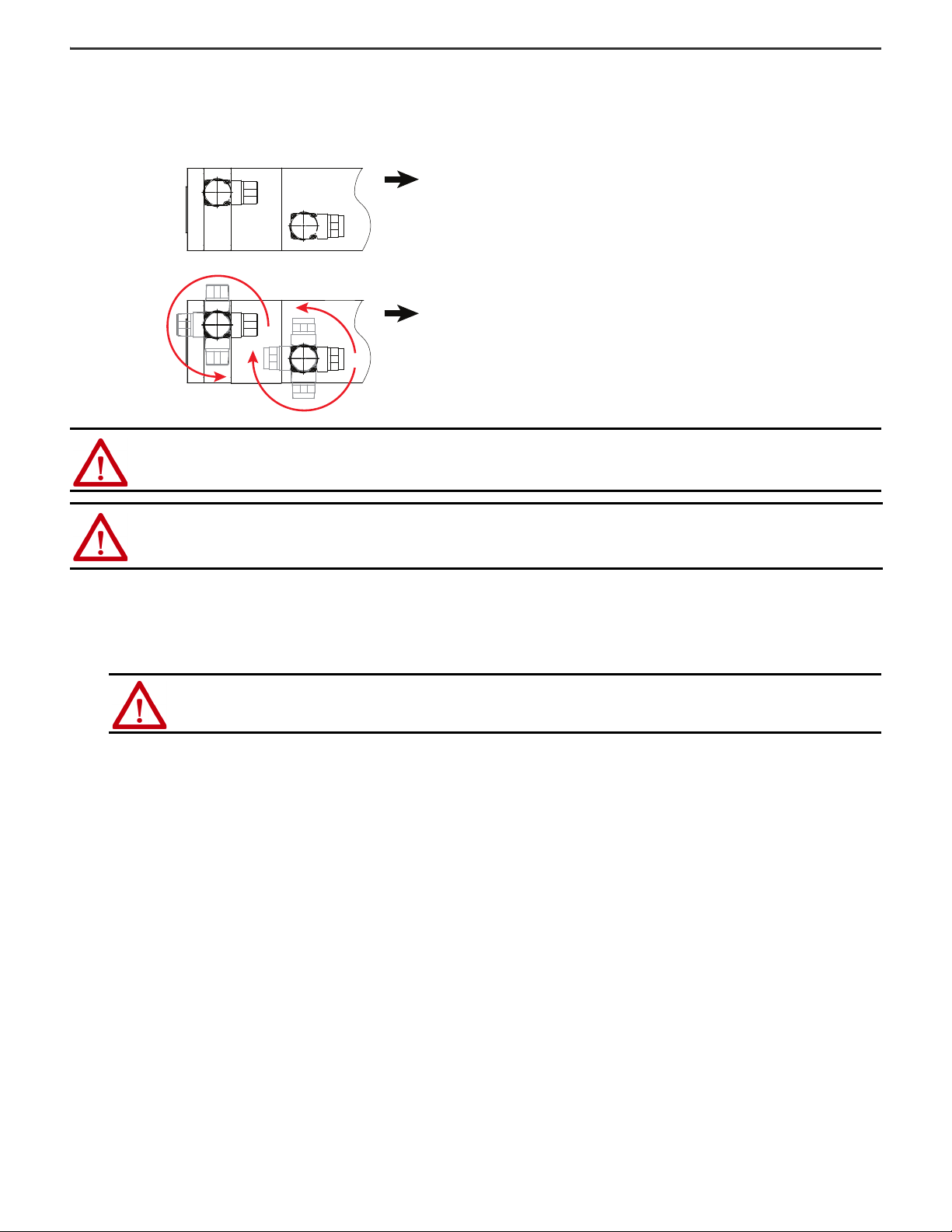
Follow these steps to rotate the DIN connectors.
1. Mount and fully seat a mating cable on the connector.
2. Grasp the connector and the cable plug by their housings and slowly rotate them to the outside of the motor.
If necessary, repeat these steps for the other connector (feedback or power/brake).
ATTENTION: Only apply force to the connectors; do not apply force to the cable. Do not use tools (for example, pliers and vise-grips) to assist
with the rotation of the connector.
Failure to observe these safety precautions could result in personal injury or damage to equipment.
10 Rockwell Automation Publication MPAI-IN001G-EN-P - March 2021
Page 11
Kinetix MPAI Heavy-duty Electric Cylinders Installation Instructions
HD
AD
B
G2
G1
AM
WH
L1
L2
L7
ZJ
B
TG1
TG2
P
L3
1.5 (0.06)
TL
RD
PD
AF
See
Detail A
Dimensions are in mm (in.)
Detail A
Power/Brake
Connector
Feedback
Connector
Dimensions ZJ and L7 are the length
when piston rod is fully retracted.
Flat for Wrench
See Detail A
Grease Fitting
(not present on MPAI-x2xxx)
S Diameter Holes on
M Diameter Bolt Circle
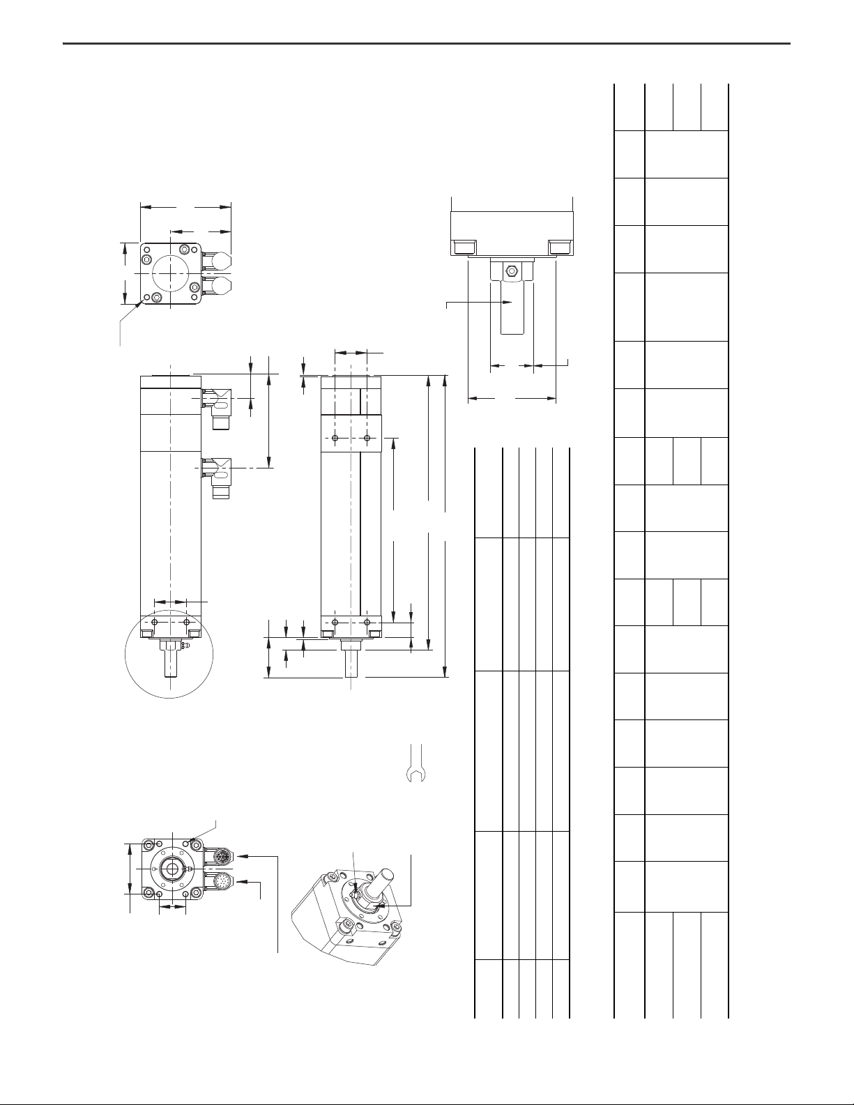
Kinetix MPAI Electric Cylinder (face-mount standard) Dimensions (Frame 64, 83, 110, and 144) MPAI-xxxxxxxxxA Face Mount (standard) Configuration
Detail A Dimensions
Frame Size
TL (threaded length, min)
mm (in.)
PD (pilot diameter)
mm (in.)
AF (across flats)
mm (in.)
RD (rod diameter)
mm (in.)
64 M10 x 1.25 x 22.1 (0.049 x 0.87) Ø 47.955…48.000 (1.8880…1.8898) 22.74…22.99 (0.895…0.905) Ø 25.38 (0.999)
83 M16 x 1.5 x 34.3 (0.06 x 1.35) Ø 59.955…60.000 (2.3604…2.3622) 26.72…26.97 (1.052…1.062) Ø 30.13 (1.186)
110 M20 x 1.5 x 41.4 (0.06 x 1.63) Ø 71.955…72.000 (2.8328…2.8346) 34.73…34.98 (1.367…1.377) Ø 38.08 (1.499)
144 M27 x 2.0 x 45.7 (0.08 x 1.80) Ø 99.955…100.000 (3.9352…3.9370) 53.73…53.98 (2.115…2.125) Ø 57.13 (2.249)
Kinetix MPAI Electric Cylinder (face-mount standard) Dimensions (Frame 64)
Electric Cylinder
Cat. No.
AD
mm (in.)
AM
mm (in.)
B
mm (in.)
G1
mm (in.)
G2
(1)
mm (in.)
(1) If ordering MPAI-A/B2xxxxVx4A actuator with brake, add 37.6 mm (1.48 in.) to dimensions G2, L7, and ZJ.
HD
mm (in.)
L1
mm (in.)
L2
mm (in.)
L3
mm (in.)
L7
(1)
mm (in.)
M
(2)
mm (in.)
(2) The tolerance for this dimension is +0.0, -0.038 mm (+0.0, -0.0015 in.).
P
mm (in.)
S
mm (in.)
TG1
mm (in.)
TG2
mm (in.)
WH
mm (in.)
ZJ
(1)
mm (in.)
MPAI-A/B2076CV12A
72.8 (2.87) 41.9 (1.65) 34.0 (1.34) 28.8 (1.13) 106.9 (4.21) 104.5 (4.11)
144.0
(5.67)
20.00
(0.787)
1.50 (0.06)
288.1
(11.34)
70.0
(2.76)
63.5 (2.50)
M6 x 1.0 x 9.0
(0.04 x 0.35)
54.0 (2.13) 20.0 (0.79) 17.3 (0.68)
263.5
(10.37)
MPAI-A/B2150CV32A
220.2
(8.67)
364.3
(14.34)
339.7
(13.37)
MPAI-A/B2300CV32A
372.6
(14.67)
516.7
(20.34)
492.1
(19.37)
Mounting Bolts (4x)
MPAI-x2xxx = M6 x 1.0 x 9.0
(0.04 x 0.35)
MPAI-x3xxx = M8 x 1.25 x 8.0
(0.05 x 0.31)
MPAI-x4xxx = M8 x 1.25 x 8.0
(0.05 x 0.31)
MPAI-x5xxx = M12 x 1.75 x 12.0
(0.07 x 0.81)
This is a bottom view, the connectors
are on the opposite side.
Dimensions
Rockwell Automation Publication MPAI-IN001G-EN-P - March 2021 11
Page 12

Kinetix MPAI Heavy-duty Electric Cylinders Installation Instructions
(1)
ZJ
mm (in.)
WH
mm (in.)
TG2
mm (in.)
TG1
mm (in.)
S
mm (in.)
P
mm (in.)
(2)
M
mm (in.)
(1)
L7
mm (in.)
376.3
(14.81)
300.0
(11.81)
413.6
(16.29)
337.6
(13.29)
681.1
(26.81)
528.7
(20.81)
69.0 (2.72) 36.0 (1.42) 17.3 (0.68)
M8 x 1.25 x 12
(0.05 x 0.47)
83.6 (3.29)
92.0
(3.622)
718.4
(28.29)
566.0
(22.29)
(1)
ZJ
mm (in.)
422.1
(16.62)
574.5
(22.62)
726.9
(28.62)
WH
mm (in.)
TG2
mm (in.)
TG1
mm (in.)
S
mm (in.)
P
mm (in.)
(2)
M
mm (in.)
(1)
L7
mm (in.)
85.0 (3.35) 55.0 (2.17) 16.8 (0.66)
M8 x 1.25 x 12
(0.05 x 0.47)
127.0 (5.0) 110.5 (4.35)
466.6
(18.37)
619.0
(24.37)
771.4
(30.37)
(1)
502.6
(19.79)
ZJ
mm (in.)
WH
mm (in.)
TG2
mm (in.)
TG1
mm (in.)
S
mm (in.)
P
mm (in.)
(2)
M
mm (in.)
(1)
L7
mm (in.)
553.4
(21.79)
655.0
(25.79)
24.1
(0.95)
65.00
(2.559)
110.00
(4.331)
M12 x 1.75 x 12
(0.07 x 0.47)
143.6
(5.66)
155.00
(6.102)
705.8
(27.79)
807.4
(31.79)
858.2
(33.79)
L3
L3
mm (in.)
L2
mm (in.)
177.0
L1
mm (in.)
HD
mm (in.)
(1)
G2
mm (in.)
G1
mm (in.)
B
mm (in.)
AM
mm (in.)
AD
mm (in.)
21.0 (0.83) 1.50 (0.06)
557.9
253.1
(9.97)
(6.97)
(21.97)
405.5
(15.97)
82.8 (3.26) 54.6 (2.15) 44.0 (1.73) 31.9 (1.25) 127.5 (5.02) 124.6 (4.90)
L3
mm (in.)
L2
mm (in.)
L1
mm (in.)
HD
mm (in.)
(1)
G2
mm (in.)
G1
mm (in.)
B
mm (in.)
AM
mm (in.)
AD
mm (in.)
25.0 (0.98) 1.50 (0.06)
295.4
(11.63)
447.8
(17.63)
600.2
(23.63)
96.3 (3.79) 61.3 (2.41) 50.0 (1.97) 31.9 (1.25) 130.7 (5.15) 151.5 (5.96)
mm (in.)
L2
mm (in.)
L1
mm (in.)
HD
mm (in.)
(1)
G2
mm (in.)
G1
mm (in.)
B
mm (in.)
AM
mm (in.)
AD
mm (in.)
1.40
(0.06)
30.00
(1.181)
648.4
(25.53)
496.0
(19.53)
343.6
(13.53)
110.1 (4.33) 74.9 (2.75) 85.00 (3.346) 34.4 (1.35) 146.8 (5.78) 181.9 (7.16)
MPAI-A/B3300xM32A
Electric Cylinder
Cat. No.
Kinetix MPAI Electric Cylinder (face-mount standard) Dimensions (Frame 83)
MPAI-A/B3150xM32A
MPAI-A/B3076xM12A
MPAI-A/B3450xM32A
(1) If ordering MPAI-A/B3xxxxMx4A actuator with brake, add 47.7 mm (1.88 in.) to dimensions G2, L7, and ZJ.
(2) The tolerance for this dimension is +0.0, -0.038 mm (+0.0, -0.0015 in.).
Electric Cylinder
Cat. No.
MPAI-A/B4150xM32A
MPAI-A/B4300xM32A
Kinetix MPAI Electric Cylinder (face-mount standard) Dimensions (Frame 110)
MPAI-A/B4450xM32A
(1) If ordering MPAI-A/B4xxxxMx4A actuator with brake, add 46.2 mm (1.81 in.) to dimensions G2, L7, and ZJ.
(2) The tolerance for this dimension is +0.0, -0.038 mm (+0.0, -0.0015 in.).
Electric Cylinder
Cat. No.
Kinetix MPAI Electric Cylinder (face-mount standard) Dimensions (Frame 144)
12 Rockwell Automation Publication MPAI-IN001G-EN-P - March 2021
MPAI-A/B5300xM32A
MPAI-A/B5150xM32A
MPAI-A/B5450xM32A
Actuators are designed to metric dimensions. Inch dimensions are approximate conversions from millimeters. Dimensions without tolerances are for reference.
(1) If ordering MPAI-A/B5xxxxMx4A actuator with brake, add 51.5 mm (2.03 in.) to dimensions G2, L7, and ZJ.
(2) The tolerance for this dimension is +0.0, -0.038 mm (+0.0, -0.0015 in.).
Page 13

Kinetix MPAI Heavy-duty Electric Cylinders Installation Instructions
TG1
TG2
WH
AM
ZJ
L7
P
AD
HD
GI
G2
L3
TL
RD
PD
AF
See
Detail A
Dimensions are in mm (in.)
Dimensions ZJ and L7 are the length
when piston rod is fully retracted.
Detail A
Detail A Dimensions
Frame Size
TL (threaded length, min)
mm (in.)
PD (pilot diameter)
mm (in.)
AF (across flats)
mm (in.)
RD (rod diameter)
mm (in.)
64 M10 x 1.25 x 22.1 (0.049 x 0.87) Ø 47.955…48.000 (1.8880…1.8898) 22.74…22.99 (0.895…0.905) Ø 25.38 (0.999)
83 M16 x 1.5 x 34.3 (0.06 x 1.35) Ø 59.955…60.000 (2.3604…2.3622) 26.72…26.97 (1.052…1.062) Ø 30.13 (1.186)
110 M20 x 1.5 x 41.4 (0.06 x 1.63) Ø 71.955…72.000 (2.8328…2.8346) 34.73…34.98 (1.367…1.377) Ø 38.08 (1.499)
144 M27 x 2.0 x 45.7 (0.08 x 1.80) Ø 99.955…100.000 (3.9352…3.9370) 53.73…53.98 (2.115…2.125) Ø 57.13 (2.249)
Kinetix MPAI Electric Cylinder (face-mount food-grade paint) Dimensions (Frame 64)
Electric Cylinder
Cat. No.
AD
mm (in.)
AM
mm (in.)
G1
mm (in.)
G2
(1)
mm (in.)
(1) If ordering MPAI-A/B2xxxxVx4E-W actuator with brake, add 37.6 mm (1.48 in.) to dimensions G2, L7, and ZJ.
HD
mm (in.)
L3
mm (in.)
L7
(1)
mm (in.)
P
mm (in.)
TG1
mm (in.)
TG2
mm (in.)
WH
mm (in.)
ZJ
(1)
mm (in.)
MPAI-A/B2076CV12E-W
72.8 (2.87) 42.1 (1.66) 26.9 (1.06) 104.6 (4.12) 104.5 (4.11) 1.8 (0.07)
285.8 (11.25)
63.5 (2.5) 54.0 (2.13) 20.0 (0.79) 17.5 (0.69)
261.2 (10.28)
MPAI-A/B2150CV32E-W 362.0 (14.25) 337.4 (13.28)
MPAI-A/B2300CV32E-W 514.4 (20.25) 489.8 (19.28)
Power/Brake
Connector
Feedback
Connector
Flat for Wrench
See Detail A
Grease Fitting
(not present on MPAI-x2xxx)
Mounting Bolts (4x)
MPAI-x2xxx = M6 x 1.0 x 9.0
(0.04 x 0.35)
MPAI-x3xxx = M8 x 1.25 x 8.0
(0.05 x 0.31)
MPAI-x4xxx = M8 x 1.25 x 8.0
(0.05 x 0.31)
MPAI-x5xxx = M12 x 1.75 x 12.0
(0.07 x 0.81)
This is a bottom view, the connectors
are on the opposite side.
Kinetix MPAI Electric Cylinder (face-mount food-grade paint) Dimensions (Frame 64, 83, 110, and 144) MPAI-xxxxxxxxxE-W Face Mount (Food-grade paint) Configuration
Rockwell Automation Publication MPAI-IN001G-EN-P - March 2021 13
Page 14

Kinetix MPAI Heavy-duty Electric Cylinders Installation Instructions
(1)
mm (in.)
ZJ
300.4 (11.83)
WH
mm (in.)
TG2
mm (in.)
TG1
mm (in.)
P
mm (in.)
(1)
L7
L3
mm (in.)
HD
mm (in.)
83.6 (3.29) 69.0 (2.72) 36.0 (1.42) 17.6 (0.69)
mm (in.)
337.6 (13.29)
(1)
422.3 (16.62)
mm (in.)
ZJ
WH
mm (in.)
TG2
mm (in.)
TG1
mm (in.)
P
(1)
L7
L3
HD
110.5 (4.35) 85.0 (3.35) 55.0 (2.17) 16.8 (0.66)
mm (in.)
466.8 (18.38)
mm (in.)
mm (in.)
mm (in.)
(1)
mm (in.)
ZJ
501.8 (19.76)
WH
mm (in.)
24.4
(0.96)
TG2
mm (in.)
65.00
(2.559)
TG1
mm (in.)
110.00
(4.331)
P
mm (in.)
143.6
(5.66)
(1)
mm (in.)
L7
552.6 (21.76)
L3
mm (in.)
HD
mm (in.)
(1)
mm (in.)
G2
G1
mm (in.)
AM
mm (in.)
AD
mm (in.)
Electric Cylinder
Cat. No.
Kinetix MPAI Electric Cylinder (face-mount food-grade paint) Dimensions (Frame 83)
82.8 (3.26) 54.9 (2.16) 30.0 (1.18) 126.0 (4.96) 124.6 (4.90) 1.8 (0.07)
MPAI-A/B3076xM12E-W
MPAI-A/B3300xM32E-W 566.0 (22.29) 529.0 (20.83)
MPAI-A/B3450xM32E-W 718.4 (28.29) 681.4 (26.83)
MPAI-A/B3150xM32E-W 413.6 (16.29) 376.6 (14.83)
(1) If ordering MPAI-A/B3xxxxMx4E-W actuator with brake, add 47.7 mm (1.88 in.) to dimensions G2, L7, and ZJ.
(1)
mm (in.)
G2
G1
mm (in.)
AM
mm (in.)
mm (in.)
MPAI-A/B4150xM32E-W
Cat. No.
96.3 (3.79) 61.5 (2.42) 30.0 (1.18) 130.8 (5.15) 151.5 (5.96) 1.8 (0.07)
MPAI-A/B4450xM32E-W 771.6 (30.38) 727.1 (28.62)
MPAI-A/B4300xM32E-W 619.2 (24.38) 574.7 (22.62)
(1) If ordering MPAI-A/B4xxxxMx4E-W actuator with brake, add 46.2 mm (1.81 in.) to dimensions G2, L7, and ZJ.
AD
Electric Cylinder
Kinetix MPAI Electric Cylinder (face-mount food-grade paint) Dimensions (Frame 110)
(1)
mm (in.)
G2
G1
mm (in.)
AM
mm (in.)
AD
mm (in.)
110.1 (4.33) 75.2 (2.96) 34.0 (1.34) 146.0 (5.75) 181.9 (7.16) 1.7 (0.07)
Electric Cylinder
Cat. No.
MPAI-A/B5150xM32E-W
MPAI-A/B5300xM32E-W 705.0 (27.76) 654.2 (25.76)
Kinetix MPAI Electric Cylinder (face-mount food-grade paint) Dimensions (Frame 144)
MPAI-A/B5450xM32E-W 857.4 (33.76) 806.6 (31.76)
Actuators are designed to metric dimensions. Inch dimensions are approximate conversions from millimeters. Dimensions without tolerances are for reference.
(1) If ordering MPAI-A/B5xxxxMx4E-W actuator with brake, add 51.5 mm (2.03 in.) to dimensions G2, L7, and ZJ.
14 Rockwell Automation Publication MPAI-IN001G-EN-P - March 2021
Page 15

HD
AD
G2
G1
AM
WH
L1
L7
ZJ
TB1
1.5 (0.06)
L3
P
MD
MD
TB2
TL
AF
RD
PD
TD
See
Detail A
Dimensions are in mm (in.)
Dimensions ZJ and L7 are the length
when piston rod is fully retracted.
Flat for Wrench
See Detail A
S Diameter Holes on
M Diameter Bolt Circle
Detail A
Detail A Dimensions
Frame Size
TL (threaded length, min)
mm (in.)
PD (pilot diameter)
mm (in.)
AF (across flats)
mm (in.)
RD (rod diameter)
mm (in.)
TD (trunnion diameter)
mm (in.)
64 M10 x 1.25 x 22.1 (0.049 x 0.87) Ø 47.955…48.000 (1.8880…1.8898) 22.74…22.99 (0.895…0.905) Ø 25.38 (0.999) Ø 11.97…11.98 (0.471…0.472)
83 M16 x 1.5 x 34.3 (0.06 x 1.35) Ø 59.955…60.000 (2.3604…2.3622) 26.72…26.97 (1.052…1.062) Ø 30.13 (1.186) Ø 15.96…15.98 (0.628…0.629)
110 M20 x 1.5 x 41.4 (0.06 x 1.63) Ø 71.955…72.000 (2.8328…2.8346) 34.73…34.98 (1.367…1.377) Ø 38.08 (1.499) Ø 19.96…19.99 (0.786…0.787)
144 M27 x 2.0 x 45.7 (0.08 x 1.80) Ø 99.955…100.000 (3.9352…3.9370) 53.73…53.98 (2.115…2.125) Ø 57.13 (2.249) Ø 24.97…24.99 (0.983…0.984)
Kinetix MPAI Electric Cylinder (trunnion-mount standard) Dimensions (Frame 64)
Electric Cylinder
Cat. No.
AD
mm (in.)
AM
mm (in.)
G1
mm (in.)
G2
(1)
mm (in.)
(1) If ordering MPAI-A/B2xxxxVx4B actuator with brake, add 37.6 mm (1.48 in.) to dimensions G2, L7, and ZJ.
HD
mm (in.)
L1
mm (in.)
L3
mm (in.)
L7
(1)
mm (in.)
M
(2)
mm (in.)
(2) The tolerance for this dimension is +0.0, -0.038 mm (+0.0, -0.0015 in.).
MD
mm (in.)
P
mm (in.)
S
mm (in.)
TB1
mm (in.)
TB2
mm (in.)
WH
mm (in.)
ZJ
(1)
mm (in.)
MPAI-A/B2076CV12B
72.8
(2.87)
41. 9
(1.65)
28.8
(1.13)
106.9
(4.21)
104.5
(4.11)
15.0
(0.591)
1.5
(0.06)
288.1
(11.34)
70.00
(2.756)
9.5
(0.38)
63.5
(2.50)
M6 x 1.0 x 9
(0.04 x 0.35)
8.7
(0.34)
2.3
(0.09)
17.3
(0.68)
263.5
(10.37)
MPAI-A/B2150CV32B
364.3
(14.34)
339.7
(13.37)
MPAI-A/B2300CV32B
516.7
(20.34)
492.1
(19.37)
Power/Brake
Connector
Feedback
Connector
Grease Fitting
(not present on MPAI-x2xxx)
Kinetix MPAI Heavy-duty Electric Cylinders Installation Instructions
Kinetix MPAI Electric Cylinder (trunnion-mount standard) Dimensions (Frame 64, 83, 110, and 144) MPAI-xxxxxxxxxB Trunnion Mount (standard) Configurations
Rockwell Automation Publication MPAI-IN001G-EN-P - March 2021 15
Page 16

Kinetix MPAI Heavy-duty Electric Cylinders Installation Instructions
(1)
376.3
(14.81)
528.7
(20.81)
681.1
16.0 (0.63) 3.2 (0.13) 17.3 (0.68)
M8 x 1.25 x 12
(0.05 x 0.47)
92.0 (3.622) 16.8 (0.66) 83.6 (3.29)
(26.81)
mm (in.)
ZJ
WH
mm (in.)
TB2
mm (in.)
TB1
mm (in.)
S
mm (in.)
P
mm (in.)
MD
mm (in.)
(2)
mm (in.)
M
(1)
422.1
(16.62)
574.5
(22.62)
726.9
mm (in.)
ZJ
WH
mm (in.)
TB2
mm (in.)
TB1
mm (in.)
S
mm (in.)
P
mm (in.)
MD
mm (in.)
(2)
M
mm (in.)
(28.62)
20.05 (0 .79) 6.25 (0.25) 1 6.8 (0.66)
M8 x 1.25 x 12
(0.05 x 0.47)
127.0 (5.0) 22.2 (0.87) 110.5 (4.35)
(1)
mm (in.)
502.6
(19.79)
655.0
(25.79)
807.4
24.9 (0.98) 8.2 (0.32) 24.1 (0.95
M12 x 1.75 x 12
(0.07 x 0.47)
155.0 (6.10) 22.2 (0.88) 143.6 (5.66)
(31.79)
ZJ
WH
mm (in.)
TB2
mm (in.)
TB1
mm (in.)
S
mm (in.)
P
mm (in.)
MD
mm (in.)
(2)
M
mm (in.)
(1)
413.6 (16.29)
mm (in.)
L7
L3
mm (in.)
L1
mm (in.)
HD
mm (in.)
(1)
mm (in.)
G2
G1
mm (in.)
AM
mm (in.)
AD
mm (in.)
82.8 (3.26) 54.6 (2.15) 30.4 (1.20) 127.5 (5.02) 124.6 (4.90) 15.00 (0.59) 1.5 (0.06)
(1)
466.6 (18.37)
mm (in.)
L7
L3
mm (in.)
L1
mm (in.)
HD
mm (in.)
(1)
mm (in.)
G2
G1
mm (in.)
AM
mm (in.)
AD
mm (in.)
96.3 (3.79) 61.3 (2.41) 30.4 (1.20) 130.7 (5.15) 151.5 (5.96) 21.00 (0.83) 1.5 (0.06)
(1)
mm (in.)
553.4 (21.79)
L7
L3
mm (in.)
L1
mm (in.)
HD
mm (in.)
(1)
mm (in.)
G2
G1
mm (in.)
AM
mm (in.)
AD
mm (in.)
110.1 (4.33) 74.9 (2.95) 34.4 (1.35) 146.8 (5.78) 181.9 (7.16) 28.0 (1.10) 1.4 (0.06)
MPAI-A/B4300xM32B 619.0 (24.37)
MPAI-A/B3300xM32B 566.0 (22.29)
MPAI-A/B3150xM32B
Electric Cylinder
Cat. No.
Kinetix MPAI Electric Cylinder (trunnion-mount standard) Dimensions (Frame 83)
MPAI-A/B3450xM32B 718.4 (28.29)
(1) If ordering MPAI-A/B3xxxxMx4B actuator with brake, add 47.7 mm (1.88 in.) to dimensions G2, L7, and ZJ.
(2) The tolerance for this dimension is +0.0, -0.038 mm (+0.0, -0.0015 in.).
Kinetix MPAI Electric Cylinder (trunnion-mount standard) Dimensions (Frame 110)
Electric Cylinder
Cat. No.
MPAI-A/B4150xM32B
MPAI-A/B4450xM32B 771.4 (30.37)
(1) If ordering MPAI-A/B4xxxxMx4B actuator with brake, add 46.2 mm (1.81 in.) to dimensions G2, L7, and ZJ.
(2) The tolerance for this dimension is +0.0, -0.038 mm (+0.0, -0.0015 in.).
Kinetix MPAI Electric Cylinder (trunnion-mount standard) Dimensions (Frame 144)
Electric Cylinder
Cat. No.
MPAI-A/B5150xM32B
16 Rockwell Automation Publication MPAI-IN001G-EN-P - March 2021
MPAI-A/B5300xM32B 705.8 (27.79)
MPAI-A/B5450xM32B 858.2 (33.79)
Actuators are designed to metric dimensions. Inch dimensions are approximate conversions from millimeters. Dimensions without tolerances are for reference.
(1) If ordering MPAI-A/B5xxxxMx4B actuator with brake, add 51.5 mm (2.03 in.) to dimensions G2, L7, and ZJ.
(2) The tolerance for this dimension is +0.0, -0.038 mm (+0.0, -0.0015 in.).
Page 17

Kinetix MPAI Heavy-duty Electric Cylinders Installation Instructions
HD
AD
G2
G1
AM
WH
L7
ZJ
L3
P
IN
OT
H
ØD
TL
RD
PD
AF
See
Detail A
Dimensions are in mm (in.)
Dimensions ZJ and L7 are the length
when piston rod is fully retracted.
Detail A
Detail A Dimensions
Frame Size
TL (threaded length, min)
mm (in.)
PD
mm (in.)
AF (across flats)
mm (in.)
RD (rod diameter)
mm (in.)
64 M10 x 1.25 x 22.1 (0.049 x 0.87) Ø 48.000 (1.89) 22.74…22.99 (0.895…0.905) Ø 25.38 (0.999)
83 M16 x 1.5 x 34.3 (0.06 x 1.35) Ø 60.000 (2.36) 26.72…26.97 (1.052…1.062) Ø 30.13 (1.186)
110 M20 x 1.5 x 41.4 (0.06 x 1.63) Ø 72.000 (2.83) 34.73…34.98 (1.367…1.377) Ø 38.08 (1.499)
144 M27 x 2.0 x 45.7 (0.08 x 1.80) Ø 100.000 (3.94) 53.73…53.98 (2.115…2.125) Ø 57.13 (2.249)
Kinetix MPAI Electric Cylinder (clevis-mount food-grade paint) Dimensions (Frame 64)
Electric Cylinder
Cat. No.
AD
mm (in.)
AM
mm (in.)
ØD
mm (in.)
G1
mm (in.)
G2
(1)
mm (in.)
(1) If ordering MPAI-A/B2xxxxVx4C-W actuator with brake, add 37.6 mm (1.48 in.) to dimensions G2, L7, and ZJ.
H
mm (in.)
HD
mm (in.)
IN
mm (in.)
L3
mm (in.)
L7
(1)
mm (in.)
OT
mm (in.)
P
mm (in.)
WH
mm (in.)
ZJ
(1)
mm (in.)
MPAI-A/B2076CV12C-W
72.8 (2.87) 41.9 (1.65)
10.01…10.02
(0.394…0.395)
26.9 (1.06) 104.6 (4.12) 13.0 (0.51) 104.5 (4.11) 26.3 (1.03) 1.5 (0.06)
285.8
(11.25)
46.25 (1.821) 63.5 (2.50) 17.3 (0.68)
261.2
(10.28)
MPAI-A/B2150CV32C-W
362.0
(14.25)
337.4
(13.28)
MPAI-A/B2300CV32C-W
514.4
(20.25)
489.8
(19.28)
Flat for Wrench
See Detail A
Power/Brake
Connector
Feedback
Connector
Grease Fitting
(not present on MPAI-x2xxx)
Kinetix MPAI Electric Cylinder (clevis-mount food-grade paint) Dimensions (Frame 64, 83, 110, and 144) MPAI-xxxxxxxxxC-W Clevis Mount (Food-grade paint) Configurations
Rockwell Automation Publication MPAI-IN001G-EN-P - March 2021 17
Page 18

Kinetix MPAI Heavy-duty Electric Cylinders Installation Instructions
(1)
mm (in.)
ZJ
WH
mm (in.)
P
mm (in.)
OT
mm (in.)
(1)
mm (in.)
L7
L3
mm (in.)
IN
mm (in.)
HD
mm (in.)
376.3
(14.81)
300.1
(11.81)
337.4
(13.28)
413 .6
(16.29)
681.1
(26.81)
528.7
(20.81)
64.3 (2.53) 83.6 (3.29) 17.3 (0.68)
718.4
(28.29)
566.0
(22.29)
(1)
mm (in.)
ZJ
WH
mm (in.)
P
mm (in.)
OT
mm (in.)
(1)
mm (in.)
L7
L3
mm (in.)
IN
mm (in.)
HD
mm (in.)
574.5
(22.62)
726.9
422.1
(16.62)
(28.62)
94.3 (3.71) 110.5 (4.35) 16.8 (0.66)
466.6
(18.37)
619.0
(24.37)
771.4
(30.37)
(1)
mm (in.)
501.8
(19.76)
ZJ
WH
mm (in.)
P
mm (in.)
OT
mm (in.)
(1)
mm (in.)
L7
L3
mm (in.)
IN
mm (in.)
HD
mm (in.)
654.2
(25.76)
806.6
(31.76)
114.30 (4.500) 143.6 (5.66) 24.1 (0.95)
552.6
(21.76)
705.0
(27.76)
857.4
(33.76)
H
H
mm (in.)
(1)
mm (in.)
G2
G1
mm (in.)
ØD
mm (in.)
AM
mm (in.)
AD
mm (in.)
Electric Cylinder
Cat. No.
Kinetix MPAI Electric Cylinder (clevis-mount food-grade paint) Dimensions (Frame 83)
82.8 (3.26) 54.6 (2.15) 12.01 (0.473) 30.0 (1.18) 127.5 (5.02) 16.0 (0.630) 124.6 (4.90) 32.3 (1.27) 1.50 (0.06)
MPAI-A/B3076xM12C-W
MPAI-A/B3300xM32C-W
MPAI-A/B3150xM32C-W
MPAI-A/B3450xM32C-W
(1) If ordering MPAI-A/B3xxxxMx4C-W actuator with brake, add 47.7 mm (1.88 in.) to dimensions G2, L7, and ZJ.
mm (in.)
(1)
mm (in.)
G2
G1
mm (in.)
ØD
mm (in.)
AM
mm (in.)
AD
mm (in.)
Electric Cylinder
Cat. No.
Kinetix MPAI Electric Cylinder (clevis-mount food-grade paint) Dimensions (Frame 110)
96.3 (3.79) 61.3 (2.41) 16.01 (0.630) 30.0 (1.18) 130.7 (5.15) 22.0 (0.866) 151.5 (5.96) 50.3 (1.98) 1.50 (0.06)
MPAI-A/B4150xM32C-W
MPAI-A/B4450xM32C-W
MPAI-A/B4300xM32C-W
(1) If ordering MPAI-A/B4xxxxMx4C-W actuator with brake, add 46.2 mm (1.82 in.) to dimensions G2, L7, and ZJ.
H
mm (in.)
(2)
mm (in.)
G2
G1
mm (in.)
(1)
mm (in.)
ØD
AM
mm (in.)
AD
mm (in.)
MPAI-A/B5150xM32C-W
Electric Cylinder
Cat. No.
Kinetix MPAI Electric Cylinder (clevis-mount food-grade paint) Dimensions (Frame 144)
18 Rockwell Automation Publication MPAI-IN001G-EN-P - March 2021
110.1 (4.33) 74.9 (2.95) 20.02 (0.788) 34.0 (1.34) 146.0 (5.75) 27.0 (1.063) 181.9 (7.16) 60.33 (2.375) 1.40 (0.06)
MPAI-A/B5300xM32C-W
MPAI-A/B5450xM32C-W
Actuators are designed to metric dimensions. Inch dimensions are approximate conversions from millimeters. Dimensions without tolerances are for reference.
(1) Tolerance for this dimension is +0.02 mm (+0.001 in.)
(2) If ordering MPAI-A/B5xxxxMx4C-W actuator with brake, add 51.5 mm (2.03 in.) to dimensions G2, L7, and ZJ.
Page 19

Kinetix MPAI Heavy-duty Electric Cylinders Installation Instructions
ACBD
E
H
L
F
G
Intercontec P/N
BEDC091NN00000202000
Intercontec P/N
AEDC113NN00000202000
Connector Data
This table lists the signal descriptions for connector pins on the electric cylinder.
Feedback Power and Brake
Pin
Signal
MPAI-Axxxxx (230V)
1 Sin+ Sin+
2 Sin- Sin-
3Cos+ Cos+
4Cos- Cos-
5 Data+ Data+
6 Data- Data-
7
8H
Reserved
9+5VDC L
10 Common Case Cable Shield and GND
11
12 Common
13
14
Reserved
(3)
TS+
(3)
TS-
15
Reserved Reserved16
17
Case Shield Shield
(1) Power pins A, B, C, and D can be labeled as U, V, W, and GND respectively.
Brake pins F and G brake can be labeled as + and - respectively.
Reserved pins E and H can be numbered 1 or 2.
(2) Brake signals (MBRK+ and MBRK-) are available only on electric cylinders with a brake.
(3) The normally closed thermal switch opens at 100 °C (212 °F).
Signal
MPAI-Bxxxxx (460V)
Reserved
+9V DC
(3)
TS+
(3)
TS-
Pin Signal Name
(1)
A
B
C
D
E
F
G
Phase U
(1)
Phase V
(1)
Phase W
(1)
Ground
(1)
Reserved
(1)
(1)
MBRK+
MBRK-
(2)
(2)
Reserved
11
1
12
13
16
10
2
9
3
17
1415
4
8
6
7
5
ATTENTION: Be sure that cables are installed and restrained to prevent uneven tension or flexing at the cable connectors. Excessive and uneven
lateral force at the cable connector can result in damage to the housing and contacts as the cable flexes.
Failure to observe these safety precautions could result in damage to the motor and its components.
Rockwell Automation Publication MPAI-IN001G-EN-P - March 2021 19
Page 20

Kinetix MPAI Heavy-duty Electric Cylinders Installation Instructions
Commissioning
This section provides guidelines for using RSLogix 5000® and MotionView OnBoard software to configure your electric cylinder servo drive system.
Required Files
Firmware revisions and software versions required to support the electric cylinders include the following:
• RSLogix 5000 software, version 16.00 or later
• Kinetix 2000, Kinetix 6000 multi-axis drives or Ultra™3000 drives with Sercos
- Firmware revision 1.96 or later
- For RSLogix 5000 software, version 16.xx,
use Motion Database file, version 4.25.0 or later
- For RSLogix 5000 software, version 17.xx or later,
use Motion Database file, version 5.18.0 or later
- For RSLogix 5000 software, version 18.xx and 19.xx,
use MPAI_5_19_11.cmf or later
• Kinetix 6200 multi-axis drives
- Firmware revision 1.30 or later
- For RSLogix 5000 software, version 17.xx,
use MPAI_5_19_11.cmf or later
• Kinetix 6500 multi-axis drives
- Firmware revision 1.11 or later
- For RSLogix 5000 software, version 18.xx,
use MPAI_5_19_11.cmf or later
• Kinetix 300 single-axis drives
- For RSLogix 5000 software, version 17.xx or later,
use Kinetix 300 drive MotionView OnBoard web interface
• Kinetix 350 single-axis Ethernet drives
- For RSLogix 5000 software, version 20.xx or later
- Firmware revision 1.30 or later
• Ultra3000 drives with Ultraware software
- Firmware revision 1.52 or later
- Motion Database (.mdb) file, dated May 2011 or later
• Motion Analyzer software, version 4.8 or later
Download these files from rok.auto/support
. Contact Rockwell Automation Technical Support at (440) 646-5800 for assistance.
Configure Your Electric Cylinder
Configure the electric cylinder by using the basic parameter settings described in this section. Use the procedure appropriate for your motion axis.
Drive See:
Kinetix 350
Kinetix 2000
Kinetix 6000
Kinetix 6200
Kinetix 6500
Ultra3000 Configure Your Servo Drive with Ultraware Software
Kinetix 300 Configure Your Kinetix 300 Servo Drive with MotionView OnBoard
IMPORTANT
Configure Your Servo Drive with RSLogix 5000 Software
ATTENTION: Moving parts can cause injuries. Before running the electric cylinder, make sure all components are secure and safe guards are in place
to prevent access to the path of moving machinery.
Have safeguards to prevent access to the electric cylinder until all motion has stopped.
Check that the electric cylinder is clear of foreign matter and tools. Objects hit by the moving thrust rod can become projectiles that can cause
personal injury or damage to the equipment.
You are responsible to verify that the servo control system safely controls the electric cylinder with regard to maximum force, acceleration, and
speed.
immediately below, and Tune Your Electric Cylinder with RSLogix 5000 Software on page 24.
on page 27.
on page 28
20 Rockwell Automation Publication MPAI-IN001G-EN-P - March 2021
Page 21

Kinetix MPAI Heavy-duty Electric Cylinders Installation Instructions
Configure Your Servo Drive with RSLogix 5000 Software
Use the following procedure to configure the drive for your electric cylinder.
The procedure assumes the Kinetix MPAI electric cylinder and the Kinetix350, Kinetix2000, Kinetix6000, Kinetix6200, or Kinetix6500 servo drive are installed and wired
as one axis of the motion system.
ATTENTION: Incorrect parameter settings can result in uncontrolled motion, with the potential for damage to the electric cylinder.
Initiating a motion command on an electric cylinder with an incorrect Position mode setting can result in damage to the electric cylinder, and the
machine in which it is installed.
1. Enter these parameters in the Axis Properties tab of RSLogix 5000 software for your electric cylinder.
Axis Properties Tab Parameter Entry/Selection
Drive/Motor
Conversion
Choose one from the pull-down menu.
MPAI-A2xxxCV1xx
MPAI-A2xxxCV3xx
MPAI-A3xxxCM1xx
MPAI-A3xxxEM1xx
MPAI-A3xxxRM1xx
MPAI-A3xxxSM1xx
Motor Catalog Number
Drive Resolution 200,000
Drive Counts per Motor Rev
Positioning Mode
Conversion Constant
Conversion Constant
MPAI-A3xxxCM3xx
MPAI-A3xxxEM3xx
MPAI-A3xxxRM3xx
MPAI-A3xxxSM3xx
MPAI-A4xxxCM3xx
MPAI-A4xxxEM3xx
MPAI-A4xxxRM3xx
MPAI-A4xxxSM3xx
MPAI-A5xxxCM3xx
MPAI-A5xxxEM3xx
Linear
Setting the Positioning Mode to Rotary can cause damage to the electric cylinder or the machine
due to incorrect positioning.
20,000 drive cnts/1.0 mm for: 508,000 drive cnts/1.0 in. for:
MPAI-x3xxxEM1xx
MPAI-x3xxxEM3xx
MPAI-x3xxxSM1xx
MPAI-x3xxxSM3xx
MPAI-x4xxxEM3xx
MPAI-
x4xxxSM3xx
MPAI-x5xxxEM3xx
40,000 drive cnts/1.0 mm for: 1,016,000 drive cnts/1.0 in. for:
MPAI-x2xxxCM1xx
MPAI-x2xxxCM3xx
MPAI-x3xxxCM1xx
MPAI-x3xxxCM3xx
MPAI-x3xxxRM1xx
MPAI-x3xxxRM3xx
MPAI-x4xxxCM3xx
MPAI-x4xxxRM3xx
MPAI-x5xxxCM3xx
MPAI-B2xxxCV1xx
MPAI-B2xxxCV3xx
MPAI-B3xxxCM1xx
MPAI-B3xxxEM1xx
MPAI-B3xxx
MPAI-B3xxxSM1xx
MPAI-B3xxxCM3xx
MPAI-B3xxxEM3xx
MPAI-B3xxxRM3xx
MPAI-B3xxxSM3xx
MPAI-B4xxxCM3xx
MPAI-B4xxxEM3xx
MPAI-B4xxxRM3xx
MPAI-B4xxxSM3xx
MPAI-B5xxxCM3xx
MPAI-B5xxxEM3xx
RM1xx
Rockwell Automation Publication MPAI-IN001G-EN-P - March 2021 21
Page 22

Kinetix MPAI Heavy-duty Electric Cylinders Installation Instructions
Axis Properties Tab Parameter Cat. No.
Entry/Selection (with applicable distance unit settings)
Metric Value mm/s English Value in/s
MPAI-x2076CM1xx 304 12.0
MPAI-x2150 CM3xx 304 12.0
MPAI-x2300CM3xx 304 12.0
MPAI-x3076CM1xx 305 12.0
MPAI-x3076EM1xx 620 25.2
MPAI-x3076RM1v 305 12.0
MPAI-x3076SM1xx 61 0 2 5.2
MPAI-x3150 CM3xx 279 11.0
MPAI-x3150EM3xx 559 22.0
MPAI-x3150 RM3xx 279 11.0
MPAI-x3150 SM3xx 559 22.0
MPAI-x3300CM3v 279 11.0
MPAI-x3300EM3xx 559 22.0
MPAI-x3300RM3xx 279 11.0
MPAI-x3300SM3xx 559 22.0
MPAI-x3450CM3xx 188 7.4
MPAI-x3450EM3xx 376 14.8
MPAI-x3450RM3xx 176 6.9
Dynamics Maximum Speed
MPAI-x3450SM3xx 353 13.9
MPAI-x415 0CM3 xx 279 11.0
MPAI-x4150EM3xx 559 22.0
MPAI-x415 0RM3 xx 279 11.0
MPAI-x415 0SM3 xx 559 22.0
MPAI-x4300CM3xx 279 11.0
MPAI-x4300EM3xx 559 22.0
MPAI-x4300RM3xx 279 11.0
MPAI-x4300SM3xx 559 22.0
MPAI-x4450CM3xx 245 9.6
MPAI-x4450EM3xx 491 19.3
MPAI-x4450RM3xx 196 7.7
MPAI-x4450SM3xx 393 13.3
MPAI-x5150CM3 xx 200 7.9
MPAI-x5150EM3 xx 400 15.7
MPAI-x5300CM3xx 200 7.9
MPAI-x5300EM3xx 400 15.7
MPAI-x5450CM3xx 200 7.9
MPAI-x5450EM3xx 400 15.7
22 Rockwell Automation Publication MPAI-IN001G-EN-P - March 2021
Page 23

Kinetix MPAI Heavy-duty Electric Cylinders Installation Instructions
2. Click the Homing tab.
3. Set parameters for either absolute homing or torque level-to-marker homing as shown in the table.
Parameter
Mode Absolute Active
Position 0, typical 0, typical
Offset N/A 0 mm
Sequence Immediate
Direction N/A Reverse Bi-directional
Torque Level N/A
Speed N/A 10 mm/s (1.97 in/s)
Return Speed N/A 10 mm/s (0.39 in/s)
(1) Torque Level-to-Marker is not available with the Kinetix 6500 drive.
Absolute Homing Torque Level-to-Marker Homing
Valu e Valu e
Torqu e Level- to-Ma rker
30%, min
Greater if the system friction, force, or weight exceeds 30% of the Continuous Force Rating at
any point in the range of motion
(1)
ATTENTION: Avoid excessive force while homing the electric cylinder. Do not exceed 10 mm/s (0.4 in/s) during a home routine.
Speeds greater than 10 mm/s (0.4 in/s) can damage the electric cylinder when the thrust rod reaches the end of travel.
4. Complete these steps for absolute homing.
a. Use motion direct commands to slowly jog your axis to the home location for your application, being sure to not exceed 10 mm/s (0.4 in/s).
b. Issue the Motion Direct Command (MAH) to set the home position on your axis.
5. Click the Limits tab.
6. Enter these parameters.
Parameter Entry/Selection, with Applicable Distance Unit Settings
Hard Travel Limits
Soft Travel Limits
Maximum Positive Enter a value that is within the thrust rod mechanical travel.
Maximum Negative Enter a value that is within the thrust rod mechanical travel.
Check if hardware limits are in use. Use Motion Analyzer
positive limits.
Check if software limits are in use. Use Motion Analyzer
positive limits.
software to determine the maximum stopping distance in your application to set negative and
software to determine the maximum stopping distance in your application to set negative and
7. Set overtravel limits according to the maximum speed of the servo drive system and the payload of the application.
IMPORTANT
Set travel limits and direction of tuning moves in reference to thrust rod starting position. Leave adequate travel for the thrust rod to
complete its moves while tuning.
ATTENTION: Software overtravel must be set before initiating the tuning process. Check the starting position of the thrust rod and allow for
adequate travel.
Insufficient travel while auto tuning causes the software overtravel to trigger an end-stop impact.
ATTENTION: Take care not to exceed the physical travel limits of the electric cylinder. Doing so causes the electric cylinder to reach the
mechanical end-of-stroke. Although protected by the end-of-stroke bumpers, frequently impacting the internal end-of-stroke bumper can
physically damage the screw and internal components of the electric cylinder.
You can determine the deceleration distance before the thrust rod contacts the end of travel based on the deceleration rate of the load, and the peak force
available from the motor/screw combination. Use Motion Analyzer
software to calculate the minimum deceleration distance at the maximum speed of your
application.
IMPORTANT
A positive-direction move command denotes a rod extend operation: a negative-direction move command denotes a retract operation.
This is when Drive Polarity is positive, which is the default setting in RSLogix 5000 software.
Rockwell Automation Publication MPAI-IN001G-EN-P - March 2021 23
Page 24

Kinetix MPAI Heavy-duty Electric Cylinders Installation Instructions
Tune Your Electric Cylinder with RSLogix 5000 Software
This section shows the steps to tune electric cylinders with RSLogix 5000 software. See Required Files on page 20 for the version number:
• Tuning your electric cylinder requires you to calculate and configure the loop gain based on the actual measured inertia.
• By setting travel limits, your application minimum deceleration is defined.
• Maximum acceleration is determined automatically during the tuning process.
Follow these steps to tune your electric cylinder.
1. In the Axis Properties dialog box, click the Fault Actions tab.
2. Click Set Custom Stop Action.
These parameter settings work best if the electric cylinder is installed in a horizontal (table top) or a wall mount (vertical) orientation.
3. In the Custom Stop Action Attributes dialog box, set the Brake Engage and the Brake Release delay times to the values listed in Specifications
4. Reduce the default Stopping Time Limit from 10 seconds to 0.5 seconds.
IMPORTANT
To prevent the rod from moving or falling when installed in a vertical orientation, the Stopping Time Limit must be set to 0.99 seconds or
less.
on page 37.
24 Rockwell Automation Publication MPAI-IN001G-EN-P - March 2021
Page 25

5. Click the Tune tab and enter these parameters:
• Travel Limit - Set to within software limits
• Speed (velocity)
• Torque/Force
Kinetix MPAI Heavy-duty Electric Cylinders Installation Instructions
IMPORTANT
Set travel limits and the direction of tuning moves in reference to the thrust rod starting position. Leave adequate travel for the thrust rod
to complete its moves while tuning.
ATTENTION: Software overtravel must be set before initiating the tuning process. Check the thrust rod starting position and allow for
adequate travel.
Insufficient travel while auto tuning causes the software overtravel to trigger an end-stop impact.
IMPORTANT
Only check Torque Offset, as shown, if the electric cylinder is installed in a non-horizontal mount position.
6. Click Start Tuning to access the Initiate Motion dialog box.
ATTENTION: Motion occurs immediately after clicking Yes in the Motion Initiation dialog box.
7. Click Yes to begin tuning the electric cylinder.
Tuning is complete when the Tune Servo dialog box opens.
Rockwell Automation Publication MPAI-IN001G-EN-P - March 2021 25
Page 26

Kinetix MPAI Heavy-duty Electric Cylinders Installation Instructions
8. Click OK to exit Tuning.
The Tune Results dialog box opens.
9. Click OK if you are satisfied with the tuning results; otherwise, continue with Calculate and Configure the Loop Gain.
Calculate and Configure the Loop Gain
Calculate a position loop bandwidth based on the actual measured inertia values from the Tune Results dialog box.
In this example, the Tune Results dialog box shows a default Position Loop Bandwidth of 45.14153 Hz, and a Load Inertia Ratio of 6.8707952.
1. Calculate the Corrected Position Bandwidth.
Corrected Position Loop Bandwidth = (Initial Position Loop Bandwidth Result/(Initial Load Inertia Ratio Result +1)
For example, 5.73532 = 45.14153/7.8707952
2. Enter the Corrected Position Bandwidth value 5.73532 as the Position Loop Bandwidth.
3. Click OK.
4. Answer the remaining dialog boxes to apply the values.
The proper Position Bandwidth results in a stable starting point, where you can adjust the gains to fit your application requirements.
26 Rockwell Automation Publication MPAI-IN001G-EN-P - March 2021
Page 27

Kinetix MPAI Heavy-duty Electric Cylinders Installation Instructions
Configure Your Servo Drive with Ultraware Software
These steps assume an electric cylinder and Ultra3000 drive are installed and wired as one axis of a motion system.
For help using Ultraware software as it applies to setting up your electric cylinder, see Additional Resources
on page 38. This procedure assumes you are familiar with
Ultraware software.
1. Connect a serial cable, catalog number 2090-DAPC-D09xx, to the CN3 connector on your Ultra3000 drive.
2. Apply AC input power to the Ultra3000 drive.
When communication with the Ultra3000 drive is established, the Ultra3000 motor database dialog box opens.
3. Click Cancel.
Ultraware software begins scanning for on-line drives. When a drive is found, an Online Drive icon opens in the Workspace.
4. Double-click the Online Drive icon to view the main Drive setup dialog box.
5. Verify the data in the Model Field is correct for your electric cylinder.
6. From the Displayed Units pull-down menu, choose User.
This programs Ultraware software to make distance moves in User Units (mm or in.).
7. Expand the Motor Encoder Units menu and enter the appropriate values from this table.
Velocity, position, and acceleration counts per unit are based on the selected User Units (mm or in.).
Cat. No.
MPAI-x2xxxC
MPAI-x3xxxC
MPAI-x3xxxE
MPAI-x3xxxR
MPAI-x3xxxS
MPAI-x4xxxC
MPAI-x4xxxE
MPAI-x4xxxR
MPAI-x4xxxS
MPAI-x5xxxC
MPAI-x5xxxE
Screw
mm/rev (in./rev)
5.0
(0.19685)
5.0
(0.19685)
10.0
(0.3937)
5.0
(0.19685)
10.0
(0.3937)
5.0
(0.19685)
10.0
(0.3937)
5.0
(0.19685)
10.0
(0.3937)
5.0
(0.19685)
10.0
(0.3937)
Encoder
periods/rev
128
1024
1024
1024
1024
1024
1024
1024
1024
1024
1024
Veloc ity S cale
mm/s (in/s)
26214.40
(665845.76)
209715.20
(2663383.04)
104857.60
(2663383.04)
209715.20
(2663383.04)
104857.60
(2663383.04)
209715.20
(2663383.04)
104857.60
(2663383.04)
209715.20
(2663383.04)
104857.60
(2663383.04)
209715.20
(2663383.04)
104857.60
(2663383.04)
Position Scale
mm (in.)
26214.40
(665845.76)
209715.20
(2663383.04)
104857.60
(2663383.04)
209715.20
(2663383.04)
104857.60
(2663383.04)
209715.20
(2663383.04)
104857.60
(2663383.04)
209715.20
(2663383.04)
104857.60
(2663383.04)
209715.20
(2663383.04)
104857.60
(2663383.04)
Acceleration Scale
mm/s/s (in/s/s)
26214.40
(665845.76)
209715.20
(2663383.04)
104857.60
(2663383.04)
209715.20
(2663383.04)
104857.60
(2663383.04)
209715.20
(2663383.04)
104857.60
(2663383.04)
209715.20
(2663383.04)
104857.60
(2663383.04)
209715.20
(2663383.04)
104857.60
(2663383.04)
Rockwell Automation Publication MPAI-IN001G-EN-P - March 2021 27
Page 28

Kinetix MPAI Heavy-duty Electric Cylinders Installation Instructions
Configure Your Kinetix 300 Servo Drive with MotionView OnBoard
Use this procedure to configure your Kinetix MPAI electric cylinder with a Kinetix 300 servo drive. See the Kinetix 300 EtherNet/IP™ Indexing Servo Drives User Manual,
publication 2097-UM001
These steps assume an electric cylinder and Kinetix 300 drive are installed and wired as one axis of a motion system.
1. Establish a connection to the Kinetix 300 servo drive via MotionView OnBoard software.
2. From the Drive Organizer, select Motor.
3. Click Change Motor.
The motor model automatically updates to the correct model number.
4. Click Yes twice.
5. Verify the motor model matches the electric cylinder model connected to the drive.
for details on using the MotionView OnBoard software.
6. From the Drive Organizer, select General.
7. Set User Units by entering values for your model from this table.
Cat. No. Lead mm/rev (in./rev) Rev/unit
MPAI-xxxxCxxx, MPAS-xxxxRMxx 5.0 (0.197) 0.2
MPAI-xxxxEMxx, MPAS-xxxxSMxx 10.0 (0.394) 0.1
8. Home the axis.
See Kinetix 300 EtherNet/IP Indexing Servo Drives User Manual, publication 2097-UM001
9. Set overtravel limits according to the maximum speed of the servo drive system and the payload of the application.
IMPORTANT
You can determine the deceleration distance before the thrust rod contacts the end of travel based on the deceleration rate of the load, and the peak force
available from the motor/screw combination. Use Motion Analyzer
application.
Set travel limits and direction of tuning moves in reference to thrust rod starting position. Leave adequate travel for the thrust rod to
complete its moves while tuning.
ATTENTION: Software overtravel must be set before initiating the tuning process. Check the starting position of the thrust rod and allow for
adequate travel.
Insufficient travel while auto tuning causes the software overtravel to trigger an end-stop impact.
ATTENTION: Take care not to exceed the physical travel limits of the electric cylinder. Doing so causes the electric cylinder to reach the
mechanical end-of-stroke. Although protected by the end-of-stroke bumpers, frequently impacting the internal end-of-stroke bumper can
physically damage the screw and internal components of the electric cylinder.
software to calculate the minimum deceleration distance at the maximum speed of your
, if you need guidance.
IMPORTANT
28 Rockwell Automation Publication MPAI-IN001G-EN-P - March 2021
A positive-direction move command denotes a rod extend operation, a negative-direction move command denotes a retract operation.
Page 29

Tune Your Electric Cylinder with MotionView OnBoard Software
1. From the Drive Organizer, select General.
2. From the Drive Mode pull-down menu, choose Autotune.
3. Enable the motor.
4. From the Drive Organizer, select Dynamics.
5. Click Autotune.
The Autotune dialog box opens with the default set to Velocity Tuning.
6. Check Velocity Tuning or Position Tuning or both.
7. Follow the instructions in the dialog box.
Kinetix MPAI Heavy-duty Electric Cylinders Installation Instructions
Maintenance
Follow these steps to maintain your electric cylinder.
1. Remove power to the electric cylinder.
Lock-out and tag-out the electric cylinder at the power source.
2. Check the axial play of the thrust rod for wear of the spindle nut.
Increased noise is one indicator of wear.
ATTENTION: If a worn spindle nut breaks on a vertically or diagonally mounted electric cylinder, the work load falls. Uncontrolled moving
mass can cause personal injury or damage to equipment.
3. Clean the electric cylinder with a soft cloth and, if needed, non-abrasive cleaning solution.
4. Lightly dampen a soft cloth with isopropyl alcohol and wipe the thrust rod and seal.
Lubrication
Your electric cylinder has been lubricated at the factory and is ready for installation. Use the appropriate lubrication interval calculations listed below for schedule
estimates or use Motion Analyzer software to calculate the recommenced re-grease schedule for the electric cylinder. For lubrication kits, see Replacement Parts and
Maintenance Kits on page 36.
ATTENTION: Overfilling of the lubricant reservoir reduces performance, and can lead to heat build-up and premature failure of the electric cylinder.
A grease gun typically delivers one gram of lubricant for one pump of the gun.
The type of lubricant and the appropriate maintenance interval is dependent on the type of electric cylinder and one or more usage factors:
• Ball screw catalog number MPAI-x2xxxC does not require lubrication.
• Ball screw (catalog number MPAI-xxxxxC or MPAI-xxxxxE) electric cylinders use Mobilith SHC220 lubricant. A maximum case temperature above or below 50 °C
(125 °F) during operation determines the lubrication interval.
• Roller screw (catalog number MPAI-xxxxxR or MPAI-xxxxxS) electric cylinders require lubrication at an interval that must be calculated. Factors in the calculation
include severity of use, screw lead pitch, and frame size.
Rockwell Automation Publication MPAI-IN001G-EN-P - March 2021 29
Page 30

Kinetix MPAI Heavy-duty Electric Cylinders Installation Instructions
100,000
10,000
1000
100
0 1 2 3 4 5 6 7 8 9
Cycle RMS Velocity (in/s)
Lubrication Interval (hr)
Basic Lubrication Interval (tbl)
Ball Screw Lubrication
Lubrication is recommended at these intervals:
• Light to moderate - The case temperature does not exceed 50 °C (125 °F), and does not require additional lubrication.
• Severe duty - The case temperature exceeds 50 °C (125 °F), and requires refilling of the lubricant reservoir through the grease fitting at 1000 hours of use.
IMPORTANT
The maximum lubricant fill capacity for ball screw drives is the following:
• 3.0 g of Mobilith SHC220 for frame size 83
• 5.0 g of Mobilith SHC220 for frame size 110
• 6.0 g of Mobilith SHC220 for frame size 144
Use Mobilith SHC220 to lubricate the ball screw. Click this link to view the Mobilith SHC220
product information.
Roller Screw Lubrication
The lubrication interval (tl) of a roller screw actuator must be calculated. Factors that influence the lubrication interval include the following:
• Frame Size - 83 or 110 mm (3.27 or 4.33 in.)
• Screw Lead - 5.0 or 10 mm/rev (0.197 or 0.394 in/rev)
• Basic lubrication interval (t
• Load correction factor (K) based on the actuator peak force (F
Use only the lubricant the factory recommends for your roller screw application.
Lubrication Interval Calculation
Use these steps to calculate the lubrication interval (tl) in hours for your roller screw electric cylinder.
1. Select the basic lubrication interval (tbl) based on the RMS velocity (V
tbl = 4500 x (V
The basic lubrication interval (tbl) falls within the range of this graph.
rms
)
-1.57
) based on RMS velocity (V
bl
, hr
rms
)
) and application maximum commanded force (FXn)
Xpeak
).
rms
2. Determine the load correction factor (K) based on the ratio of actuator peak force (F
IMPORTANT
Load Correction (K) must not be greater than one (<1).
Frame Size 83, 5 mm Roller Screw Load Correction
K
MPAI-x3xxxSM3xx
= 0.24 (F
Xpeak/FXn
)-0.15
Frame Size 83, 10 mm Roller Screw Load Correction
K
MPAI-x3xxxSM3xx
Frame Size 110, 5 mm Roller Screw Load Correction
K
MPAI-x4xxxSM3xx
= 0.44 (F
= 0.26 (F
Xpeak/FXn
Xpeak/FXn
)-0.15
)-0.15
Frame Size 110, 10 mm Roller Screw Load Correction
K
MPAI-x4xxxSM3xx
= 0.40 (F
Xpeak/FXn
)-0.15
30 Rockwell Automation Publication MPAI-IN001G-EN-P - March 2021
) to the application maximum commanded force (FXn).
Xpeak
Page 31

Kinetix MPAI Heavy-duty Electric Cylinders Installation Instructions
3. Calculate the lubrication interval (tl) in hours.
t
= tbl x K, h
1
Use the basic lubrication interval (tbl) and the load correction factor (K) from step 1 and step 2.
4. When the calculated lubrication interval elapses, refill the lubricant reservoir through the grease fitting.
IMPORTANT
The maximum lubricant fill capacity for a roller screw drive is the following:
• 3.0 g of factory recommended lubricant for frame size 83
• 5.0 g of factory recommended lubricant for frame size 110
Lubrication Calculation Example
The following is an example of lubrication interval calculation for MPAI-x3xxxRMxx electric cylinder.
Operators
Variable Description
F
xpeak
F
xn
K Load correction factor
S
co
t
bl
V
rms
Screw Static Load Factors
Cat. No.
MPAI-x3xxxRM3xx 0.24
MPAI-x3xxxSM3xx 0.44
MPAI-x4xxxRM3xx 0.26
MPAI-x4xxxSM3xx 0.40
Actuator peak force
Application maximum command force
Screw static load factor
Basic lubrication interval
RMS velocity
S
co
EXAMPLE
Product MPAI-x3xxxRM3xx
V
F
F
t
bl
K
t
l
1.66 in/s
rms
1700 lbf
xpeak
400 lbf
xn
= 4500 x (1.66 in/s)-1.57 = 2030 hr
MPAI-x3xxxRM3xx
= 0.24 (1700 lbf/400 lbf)
-0.15
= 0.87
= 2030 x (0.87) = 1766 hr
Storage
Store your electric cylinder for a minimal amount of time in a clean and dry location within the Environmental Specifications on page 37.
Observe these conditions when storing the electric cylinder:
• Be sure the equipment is in good working order before storing. Perform repairs, maintenance, and inspections before storing equipment.
• Store the equipment in a suitable storage position (horizontal) this prevents damage to the connectors and electronics.
• After 6 months of storage, cycle the equipment two complete strokes to redistribute the internal lubricants.
• After storage for a period longer than 2 years without use, lubricant replacement is recommended through Rockwell Automation Technical Support.
Rockwell Automation Publication MPAI-IN001G-EN-P - March 2021 31
Page 32

Kinetix MPAI Heavy-duty Electric Cylinders Installation Instructions
Troubleshoot Kinetix MPAI Electric Cylinders
Troubleshoot Electric Cylinders
Description Possible cause Corrective action
Axial play too large. Wear
Distortions
Squeaking noises or vibrations.
Thrust rod does not move.
No response from electric cylinder.
Electric cylinder is enabled but not operating or is
operating erratically.
Electric cylinder is operating but is not up to rated speeds/
forces.
Electric cylinder cannot move load.
Electric cylinder moves or vibrates when thrust rod is in
motion.
Actuator is overheating.
Tuning is necessary. Modify control parameters.
Running noises at the spindle support of an electric
cylinder with a 300 mm (11.81 in.) stroke and high
positioning speeds.
Jamming in mechanical end position, after traveling at
excessive speed or into end position.
Load is too large.
Ambient temperature too low (increased breakaway
torque in initial run due to increasing viscosity of the
lubricants in the spindle system).
Controller/drive not enabled. Enable controller/drive.
Controller/drive faulted. Reset the controller/drive.
Improper/failed wiring. Check the wiring.
Feedback cable can be damaged. Test the feedback cable.
Feedback wiring can be incorrect. Verify correct feedback wiring.
Motor phases are wired incorrectly or in incorrect order. Verify correct motor power wiring.
Amplifier can be improperly tuned. Verify gain settings.
Amplifier can be configured improperly for electric
cylinder used.
Force is too large for the capacity of the electric cylinder
or too much friction is present.
Misalignment of thrust rod to load. Verify load alignment.
Amplifier has too low of current capacity or is limited to
too low of current capacity.
Loose mounting. Verify actuator mounting.
Amplifier is improperly tuned or gain setting is wrong. Tune amplifier.
Duty cycle is higher than actuator rating. Verify load forces and electric cylinder rating.
Actuator operated outside of continuous rating. Adjust operation to be within continuous operation rating.
Amplifier is poorly tuned, requiring excessive current be
applied to the motor.
• Replace actuator cylinder.
• Send to Rockwell Automation for repair.
• Verify the electric cylinder is free of stress and evenly supported
0.2 mm (0.008 in.).
• Lubricate thrust rod. See Configure Your Kinetix 300 Servo Drive with
MotionView OnBoard on page 28.
• Modify positioning speed.
Normal, no impairment of function.
• Loosen jamming manually.
– Switch off power supply.
– Remove motor and coupling housing.
– Turn drive shaft.
• Reduce speed for reference travel.
• Provide software end positions, at least 0.25 mm (0.01 in.) from the
mechanical end positions (stops).
• Reduce load mass.
• Reduce positioning speed.
• Return for repairs.
• Reduce load mass.
• Reduce positioning speed.
• If necessary, allow higher current with servo motors (see operating
instructions for the motor).
• Increase ambient temperature.
Verify amplifier setting for number of poles, voltage, current,
resistance, inductance, inertia, and other motor settings.
Verify force requirements.
Verify correct amplifier and settings.
Verify gain settings.
32 Rockwell Automation Publication MPAI-IN001G-EN-P - March 2021
Page 33

Kinetix MPAI Heavy-duty Electric Cylinders Installation Instructions
Electric Cylinder
MPAI-A/BxxxxxM3xA
and Accessories
Trunnion-mount Electric Cylinder
MPAI-A/BxxxxxM3xB
and Accessories
3
4
6
5
6
5
1
Trunnion Mount (x2)
2
7
7
Accessories
This diagram depicts the accessories available for the electric cylinders. Tables list the catalog number and weight for each accessory. See the Kinetix Linear Motion
Specifications Technical Data, publication KNX-TD002
Mounting Accessories
, for accessory dimensions.
Accessory Item Frame Cat. No.
64 MPAI-NA206 500 (17.6)
1 Mounting plates
2Rear clevis mount
83 MPAI-NA306 920 (32.5) 83 MPAI-NA301 1070 (37.7)
110 MPAI-NA406 1150 (40.6) 110 MPAI-NA401 1740 (61.4)
144 MPAI-NA506 3080 (108.6) 144 MPAI-NA501 4170 (147.1)
64 MPAI-NA203 310 (10.9)
83 MPAI-NA303 700 (24.7) 83 MPAI-NA321 1090 (38.4)
110 MPAI-NA403 1430 (12.3) 110 MPAI-NA421 1770 (62.4)
144 MPAI-NA503 3010 (106.2) 144 MPAI-NA521 4250 (149.9)
Anti-rotation Guide Accessory
Accessory Item Frame Cat. No.
MPAI-NE20276 330 (11.6)
64
4
Anti-rotation guide
83
Rod-end Accessories
Accessory Item Frame Cat. No.
5Rod clevis
6Rod eye
MPAI-NE20215 370 (13.1) MPAI-NE40230 980 (34.6)
MPAI-NE20230 450 (15.9) MPAI-NE40245 1130 (39.8)
MPAI-NE30276 660 (23.3)
MPAI-NE30215 740 (26.1) MPAI-NE50230 2660 (93.8)
MPAI-NE30230 890 (31.4) MPAI-NE50245 3000 (106.0)
MPAI-NE30245 1040 (36.7)
64 MPAI-NE204 100 (3.5)
83 MPAI-NE304 350 (12.3) 83 MPAI-NE301 660 (23.3)
110 MPAI-NE404 710 (25.0) 110 MPAI-NE401 730 (25.7)
144 MPAI-NE504 2030 (71.6) 144 MPAI-NE501 2200 (77.6)
64 MPAI-NE203 90 (3.2)
83 MPAI-NE303 255 (9.0) 83 MPAI-NE323 210 (7.4)
110 MPAI-NE403 497 (17.5) 110 MPAI-NE423 380 (13.4)
144 MPAI-NE503 1330 (46.9) 144 MPAI-NE523 1300 (45.8)
Weight, approx
g (oz)
Weight, approx
g (oz)
Weight, approx
g (oz)
Accessory Item Frame Cat. No.
64 MPAI-NA201 490 (17.3)
3 Front flange mount
64 MPAI-NA221 500 (17.6)
Front flange mount
3
(stainless steel)
Accessory Item Frame Cat. No.
MPAI-NE40215 820 (28.9)
110
4 Anti-rotation guide
144
Accessory Item Frame Cat. No.
7 Alignment coupler
Rod eye
6
(corrosion resistant)
MPAI-NE50215 2330 (82.2)
64 MPAI-N201 220 (7.8)
64 MPAI-NE223 70 (2.5)
Weigh t, ap prox
g (oz)
Weight, approx
g (oz)
Weight, approx
g (oz)
Rockwell Automation Publication MPAI-IN001G-EN-P - March 2021 33
Page 34

Kinetix MPAI Heavy-duty Electric Cylinders Installation Instructions
1
2
3
4
5
6
7
8
9
Anti-rotation Option
The design of the Kinetix MPAI electric cylinder allows the extending rod to rotate. This provides simple setup of the actuator because you can rotate the rod and thread it in
and out of the actuator for mechanical attachment or system testing. This feature also requires that the rod be kept from rotating when used in its dedicated application to
be sure of proper linear motion. In most applications, such as those where the load is coupled to linear bearings, or some other support device, the load cannot rotate, and
thus provides anti-rotation for the extending rod of the actuator.
For applications where load is free to rotate, Rockwell Automation offers the anti-rotation systems shown below.
ATTENTION: The anti-rotation option is not a guide or support mechanism. It is intended as an anti-rotation device only.
Anti-rotation Option
Item Description Item Description
1 Anti-rotation shaft fastener 6 Bearing block
2Anti-rotation clamp 7Washers
3 Thrust rod fastener 8 Bearing block fasteners
4 Grease zerk 9 Anti-rotation shaft
5Rod-end
34 Rockwell Automation Publication MPAI-IN001G-EN-P - March 2021
Page 35

Kinetix MPAI Heavy-duty Electric Cylinders Installation Instructions
Install the Anti-rotation Option
Recommended tools include 4, 5, 6, and 10 mm hex keys (Allen wrenches) and small dead blow hammer.
ATTENTION: Improper alignment of the anti-rotation shaft can result in binding and or side loading that can reduce the life of the actuator.
ATTENTION: Take precautions to not cause damage to the actuator’s grease zerk fitting throughout the following process.
ATTENTION: This procedure requires you to rotate the thrust rod. Rotating the thrust rod causes the factory set home position to be lost and require
the electric cylinder be homed before its initial use.
Follow these steps to install the anti-rotation option.
1. Assemble the anti-rotation shaft fastener into the anti-rotation clamp finger-tight, then back off one turn.
2. Assemble the anti-rotation clamp on to the rod end, orientated such that the shallow counter-bore faces the non-working end of the actuator and the clamp’s
opening straddles the grease Zerk fitting.
3. Engage the flats of the anti-rotation clamp with the flats of the rod end.
Light tapping with a dead-blow hammer can be necessary to seat the anti-rotation clamp against the thrust tube.
4. Torque the anti-rotation shaft fastener to 7.8 N•m (5.8 lb•ft) while making sure the anti-rotate clamp does not shift.
5. Apply medium strength thread-locker to the two bearing block fasteners.
6. Assemble the bearing block on to the actuator finger-tight only by using the two fasteners and two washers, oriented such that the bearing block does not breech
the face of the actuator.
7. Insert the anti-rotation shaft through the bearing block, orientated with the shaft’s tapped hole facing the working end of the actuator.
8. Light tapping with the dead-blow hammer can be necessary to get the anti-rotation shaft through the oil wick of the bearing block.
9. Manually rotate the thrust rod to retract the actuator as far as the application allows without mechanically stopping or striking any mounting means.
10. Verify that the bearing block fasteners are just finger-tight allowing the bearing block to float.
11. Align the shallow counter-bore of the anti-rotation clamp with the anti-rotation shaft, engage the shaft into the counter-bore.
12. Apply medium strength thread-locker to the anti-rotate shaft fastener and assemble through the anti-rotate clamp and into the anti-rotate shaft; torque to the
value shown on the table.
Frame Size Torque
64
7.8 N•m (5.75 l b•ft)83
110
144 20.3 N•m (15.0 lb•ft)
13. Torque the two bearing block fasteners as shown in the table.
Frame Size Torque
64 13.2 N•m (9.7 lb•ft)
83
110
144 56.5 N•m (70.0 lb•ft)
39.5 N•m (29.13 lb•ft)
14. Use the procedure in Configure Your Servo Drive with RSLogix 5000 Software
on page 21 to re-establish home.
Rockwell Automation Publication MPAI-IN001G-EN-P - March 2021 35
Page 36

Kinetix MPAI Heavy-duty Electric Cylinders Installation Instructions
O-ring
Air Fitting
Tor x Sc rew
M3 x 10 mm Flat Head
Feedback connector attaches
to a rotary or linear motion
device that is not shown.
Kinetix MPAI Sealing Air Pressure Kit
A sealing air pressure kit (catalog number MPF-7-AIR-PURGE) is available for field installation on an M23 feedback connector. Positive air pressure supplied through the kit
provides an additional level of protection against the ingress of foreign substances and moisture.
The kit replaces the M23 feedback connector cap, provides a replacement O-ring, and includes installation instructions. You must supply 4 mm (5/32 in.) OD Teflon FEP
tubing, and an external air supply that does exceed 0.1 bar (1.45 psi).
Air Pressure Kit Installation on an M23 Feedback Connector
Replacement Parts and Maintenance Kits
Item Cat. No. Description
1
2 MPAI-NR004 Grease plug, five per package
3 MPAI-NR003 Zerk fitting, five per package
4 MPAI-NR005 Zerk fitting replacement cap, five per package
N/A MPAI-NR001
N/A MPAI-NR002
(1) All MPAI electric cylinders have been standardized on the Se ries B construction NR06 front wiper seal kits. MPAI-x3 and MPAI-x4 made before
mid 2012 have a front bearing block NR07 (Series A) in their construction. Check your MPAI-x3 and MPAI-x4 actuator nameplate for Series A or
Series B before specifying replacement front wiper seal kits.
(2) Fits a standard grease gun with 52 mm (2.0 in.) piston.
1
MPAI-NR206 Viton rod wiper seal kit (64 frame)
MPAI-NR306
MPAI-NR406
MPAI-NR506 Viton rod wiper seal kit (144 frame)
MPAI-NR307 Front bearing and wiper seal kit for Series A non-food grade white paint (83 frame)
MPAI-NR407 Front bearing and wiper seal kit for Series A non-food grade white paint (110 frame)
Viton rod wiper seal kit (83 frame)
Viton rod wiper seal kit (110 frame)
Roller screw grease kit, contains one 414 ml (14 oz.) tube
Ball screw grease kit, contains one 414 ml (14 oz.) tube
2
3
4
1
(1)
(1)
(2)
(2)
36 Rockwell Automation Publication MPAI-IN001G-EN-P - March 2021
Page 37

Kinetix MPAI Heavy-duty Electric Cylinders Installation Instructions
Specifications
Electric Cylinder Weights
Electric Cylinder
(frame 64) Cat. No.
Weight, approx
kg (lb)
Electric Cylinder
(frame 83) Cat. No.
Weigh t, ap prox
kg (lb)
Electric Cylinder
(frame 110) Cat. No.
Weight, approx
kg (lb)
Electric Cylinder
(frame 144) Cat. No.
(1)
MPAI-x2076CV12x 3.2 (7.1) MPAI-x3076xM12x 6.2 (13.7) MPAI-x4150 xM32x 15.8 (34.8) MPAI-x5150 xM32x 32.1 (70.7)
MPAI-x2150C V32x 4.7 (10.4) MPAI-x3150xM32x 8.3 (18.3) MPAI-x4300xM32x 18.8 (41.4) MPAI-x5300xM32x 37.8 (83.3)
MPAI-x2300CV32x 5.8 (12.8) MPAI-x3300xM32x 10.1 (22.2) MPAI-x4450xM32x 21. 8 (48.0) MPAI-x5450xM32x 43.6 (96.1)
N/A MPAI-x3450xM32x 11.9 (26.2) MPAI-x415 0xM34x 17.3 (38.1) MPAI-x5150xM34x 34.4 (75.8)
MPAI-x2076CV14x 3.7 (8.2) MPAI-x3076xM14x 7.2 (15.9) MPAI-x4300xM34x 20.3 (44.7) MPAI-x5300xM34x 40.2 (88.6)
MPAI-x2150C V34x 5.2 (11.5) MPAI-x3150xM34x
9.3 (20.5) MPAI-x4450xM34x 23.3 (51.4) MPAI-x5450xM34x 45.9 (101.2)
MPAI-x2300CV34x 6.3 (13.9) MPAI-x3300xM34x 11.1 (24.4)
N/A MPAI-x3450xM34x 12.9 (28.4)
(1) For MPAI-x2xxxCVxx-W (rear clevis mount) cylinders, add 0.2 kg (0.44 lb).
(2) Includes MPAI-x5xxxxM3xA and MPAI-x5xxxxM3xE-W (front face mount) cylinders.
(3) For MPAI-x5xxxxM3xB (front trunnion mount) cylinders, add 0.5 kg (1.1 lb).
(4) For MPAI-x5xxxxM3xC-W (rear clevis mount) cylinders, add 2.1 kg (4.6 lb).
Environmental Specifications
Attribute Value
Temperature, operating ambient 0…40 °C (32…104 °F)
Temperature, storage ambient -25…60 °C (-13…140 °F)
Humidity, relative (noncondensing) 5…95%
Liquid/dust protection
IP66/IP67 in a static condition - Total protection from dust and protected against the effects of temporary liquid immersion.
Shock, max 20 g peak, 6 ms duration
Vibration, max
(1) Rockwell Automation factory-delivered 2090-Series cable connectors are required to achieve this International Protection (IP) rating for the complete unit.
(2) Tested for one hour per Rockwell Automation specification 10000056670. Contact your distributor for a copy of this specification.
(2)
2.5 g peak @ 30…2000 Hz
Brake Specifications
Wei ght ,
(2)
approx
kg (lb)
(3) (4)
(1)
Cat. No. Static Torque Coil Current at 24V DC
MPAI-A/B2xxxxVx4x 1.6 N•m (14.0 lb•in)
MPAI-A/B3xxxxM34x 4.0 N•m (35.4 lb•in)
MPAI-A/B4xxxxM34x 10.0 N•m (88.5 lb•in)
MPAI-A/B5xxxxM34x 16.4 N•m (145 lb•in)
(1) Brake engage time delay with voltage removed and a metal oxide varistor (MOV) used for arc suppression.
Use of a diode array for arc suppression approximately doubles (x2) the engage time delay.
(2) Brake release time delay with voltage applied.
0.35 A
0.43 A
0.67 A
0.66 A
peak
peak
peak
peak
Engage
75 ms 20 ms
40 ms 50 ms
25 ms 35 ms
15 ms 25 ms
Brake Response Time
(1)
Release
Estimated Brake Holding Force
Cat. No.
MPAI-A/Bxxxx Cxxx
N (lb)
MPAI-A/Bxxxx Exxx
N (lb)
(1)
MPAI-A/B2xxxxV34x 23 00 ( 517) N/A N/A N/A
MPAI-A/B3xxxxM34x 5818 (1308) 2909 (654) 6423 (1444) 3211 (722)
MPAI-A/B4xxxxM34x 14550 (3271) 7272 (1635) 16062 (3611) 8029 (1805)
MPAI-A/B5xxxxM34x 23838 (5359) 11921 (2680) N/A N/A
(1) MPAI-A/BxxxxCxxx and MPAI-A/BxxxxExxx have ball screw actuators of 5 mm and 10 mm respectively.
(2) MPAI-A/BxxxxRxxx and MPAI-A/BxxxxSxxx have roller screw actuators of 5 mm and 10 mm respectively.
(1)
MPAI-A/Bxxxx Rxxx
N (lb)
(2)
MPAI-A/Bxxxx Sxxx
N (lb)
(2)
(2)
Rockwell Automation Publication MPAI-IN001G-EN-P - March 2021 37
Page 38

Kinetix MPAI Heavy-duty Electric Cylinders Installation Instructions
Additional Resources
These documents contain additional information concerning related products from Rockwell Automation.
Resource Description
Kinetix Linear Motion Specifications Technical Data, publication KNX-TD002
Kinetix Servo Drives Specifications, publication KNX-TD003
Kinetix Motion Accessories Specifications, publication KNX-TD004
Kinetix 5500 Drive Systems Design Guide, publication KNX-RM009
Kinetix 5700 Drive Systems Design Guide, publication KNX-RM010
Kinetix 5100 Drive Systems Design Guide, publication KNX-RM011
Kinetix 5300 Drive Systems Design Guide, publication KNX-RM012
Kinetix 300 EtherNet/IP Indexing Servo Drives User Manual, publication 2097-UM001
Kinetix 350 Single-axis EtherNet/IP Servo Drives User Manual, publication 2097-UM002
Kinetix 2000 Multi-axis Servo Drives User Manual, publication 2093-UM001
Kinetix 6000 Multi-axis Servo Drives User Manual, publication 2094-UM001
Kinetix 6200 and Kinetix 6500 Modular Multi-axis Servo Drives User Manual,
publication 2094-UM002
Ultra3000 Digital Servo Drives Installation Manual, publication 2098-IN003
Ultra3000 Digital Servo Drives Integration Manual, publication 2098-IN005
Kinetix Motion Control Selection Guide, publication KNX-SG001
Ultraware Software User Manual, publication 2098-UM001
Motion Analyzer software, access online at
https://motionanalyzer.rockwellautomation.com/
Sercos and Analog Motion Configuration User Manual, publication MOTION-UM001
System Design for Control of Electrical Noise Reference Manual, publication GMC-RM001
Servo Drive Installation Best Practices Application Technique,
publication MOTION-AT004
Rockwell Automation Product Selection website, rok.auto/systemtools
Product Certifications website rok.auto/certifications
Product specifications for Kinetix MPAS/MPMA, MPAR, VPAR, and MPAI linear actuators; LDAT-Series
linear thrusters; LDC-Series™ and LDL-Series™ linear motors.
Provides product specifications for Kinetix Integrated Motion over EtherNet/IP, Integrated Motion
over sercos interface, EtherNet/IP networking, and component servo drive families.
Provides product specifications for 2090-Series motor and interface cables, low-profile connector
kits, drive power components, and other servo drive accessory items.
How to install, configure, and troubleshoot a Kinetix servo drive system.
Provides an overview of Kinetix servo drives, motors, actuators, and motion accessories designed to
help make initial decisions for the motion control products that are best suited for your system
requirements.
Provides detailed installation instructions, defines software interface features, and programming
assistance for Ultraware software.
Provides comprehensive motion application sizing tool used for analysis, optimization, selection,
and validation of your Kinetix Motion Control system.
Information on configuring and troubleshooting your ControlLogix® and CompactLogix™ Sercos
interface modules, and using the home to torque-level sequence.
Information, examples, and techniques designed to minimize system failures caused by electrical
noise.
Best practice examples to help reduce the number of potential noise or electromagnetic
interference (EMI) sources in your system and to make sure that the noise sensitive components are
not affected by the remaining noise.
Provides online product selection and system configuration tools, including AutoCad (DXF) drawings.
Provides declarations of conformity, certificates, and other certification details.
You can view or download publications at rok.auto/literature
.
38 Rockwell Automation Publication MPAI-IN001G-EN-P - March 2021
Page 39

Notes:
Kinetix MPAI Heavy-duty Electric Cylinders Installation Instructions
Rockwell Automation Publication MPAI-IN001G-EN-P - March 2021 39
Page 40

Rockwell Automation Support
Use these resources to access support information.
Technical Support Center Find help with how-to videos, FAQs, chat, user forums, and product notification updates. rok.auto/support
Knowledgebase Access Knowledgebase articles. rok.auto/knowledgebase
Local Technical Support Phone Numbers Locate the telephone number for your country. rok.auto/phonesupport
Literature Library Find installation instructions, manuals, brochures, and technical data publications. rok.auto/literature
Product Compatibility and Download Center (PCDC) Download firmware, associated files (such as AOP, EDS, and DTM), and access product release notes. rok.auto/pcdc
Documentation Feedback
Your comments help us serve your documentation needs better. If you have any suggestions on how to improve our content, complete the form at rok.auto/docfeedback.
Waste Electrical and Electronic Equipment (WEEE)
At the end of life, this equipment should be collected separately from any unsorted municipal waste.
Rockwell Automation maintains current product environmental compliance information on its website at rok.auto/pec.
Your comments help us serve your documentation needs better. If you have any suggestions on how to improve our content, complete the form at rok.auto/docfeedback.
For technical support, visit
Rockwell Otomasyon Ticaret A.Ş. Kar Plaza İş Merkezi E Blok Kat:6 34752 İçerenköy, İstanbul, Tel: +90 (216) 5698400 EEE Yönetmeliğine Uygundur
Allen-Bradley, CompactLogix, ControlLogix, expanding human possibility, Kinetix, Rockwell Automation, RSLogix 5000, and Ultra are trademarks of Rockwell Automation, Inc.
EtherNet/IP is a trademark of ODVA, Inc.
Trademarks not belonging to Rockwell Automation are property of their respective companies.
Publication MPAI-IN001G-EN-P - March 2021 | Supersedes Publication MPAI-IN001F-EN-P-August 2016
Copyright © 2021 Rockwell Automation, Inc. All rights reserved. Printed in the U.S.A.
rok.auto/support.
 Loading...