


 Loading...
842E EtherNet/IP™Absolute Encoder
User Manual
Important User Information
Solid-state equipment has operational characteristics differing from those of electromechanical equipment. Safety Guidelines for the Application, Installation and Maintenance of Solid-State Controls (publication
SGI 1.1 available from your local Rockwell Automation sales office or online at http://literature.rockwellautomation.com) describes some important differences between solid-state
equipment and hard-wired electromechanical devices. Because of this difference, and also because of the wide variety of uses for solid-state equipment, all persons responsible for applying this equipment must satisfy themselves that each intended application of this equipment is acceptable.
In no event will Rockwell Automation, Inc. be responsible or liable for indirect or consequential damages resulting from the use or application of this equipment.
The examples and diagrams in this manual are included solely for illustrative purposes. Because of the many variables and requirements associated with any particular installation, Rockwell Automation, Inc. cannot assume responsibility or liability for actual use based on the examples and diagrams.
No patent liability is assumed by Rockwell Automation, Inc. with respect to use of information, circuits, equipment, or software described in this manual.
Reproduction of the contents of this copyrighted publication, in whole or part, without written permission of Rockwell Automation, is prohibited.
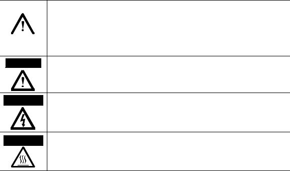
Throughout this manual we use notes to make you aware of safety considerations:
|
WARNING |
|
Identifies information about practices or circumstances that can cause an explosion in |
||
|
|
|
|
|
a hazardous environment, which may lead to personal injury or death, property |
|
|
|
|
||
|
|
|
|
|
damage, or economic loss. |
|
|
|
|
|
|
|
|
|
|
|
|
|
|
|
|
|
|
|
|
|
|
|
Identifies information that is critical for successful application and understanding of |
|
IMPORTANT |
|
|||
|
|
the product. |
|||
|
|
|
|
|
|
ATTENTION Identifies information about practices or circumstances that can lead to personal  injury or death, property damage, or economic loss. Attentions help you identify a hazard, avoid a hazard, and recognize the consequences.
SHOCK HAZARD Labels may be on or inside the equipment (for example, drive or motor) to alert people that dangerous voltage may be present.
BURN HAZARD Labels may be on or inside the equipment (for example, drive or motor) to alert people that surfaces may reach dangerous temperatures.
Rockwell Automation, Allen-Bradley, RSLinx, RSLogix, and RSLogix 5000 are trademarks of Rockwell Automation, Inc.
Trademarks not belonging to Rockwell Automation are property of their respective companies.
It is recommended that you save this user manual for future use.

|
|
Table of Contents |
|
About this document |
|
|
Who should use this manual . . . . . . . . . . . . . . . . . . . . . . . . |
. . . . . . . . . . . . . . . iii |
|
Purpose of this manual . . . . . . . . . . . . . . . . . . . . . . . . . . . . . . |
. . . . . . . . . . . . . . iii |
|
Related documentation . . . . . . . . . . . . . . . . . . . . . . . . . . . . . . |
. . . . . . . . . . . . . . iii |
|
Common techniques used in this manual . . . . . . . . . . . . . |
. . . . . . . . . . . . . . iii |
|
Chapter 1 |
|
Safety |
Authorized personnel . . . . . . . . . . . . . . . . . . . . . . . . . . . . . . . |
. . . . . . . . . . . . . . . 1 |
|
Correct use . . . . . . . . . . . . . . . . . . . . . . . . . . . . . . . . . . . . . . . . . |
. . . . . . . . . . . . . . . 1 |
|
General safety notes and protective measures . . . . . . . . . . |
. . . . . . . . . . . . . . . 2 |
|
Environmental protection . . . . . . . . . . . . . . . . . . . . . . . . . . . |
. . . . . . . . . . . . . . . 2 |
|
Chapter 2 |
|
Encoder overview |
Overview of the encoder . . . . . . . . . . . . . . . . . . . . . . . . . . . . . |
. . . . . . . . . . . . . . . 3 |
|
What is an encoder? . . . . . . . . . . . . . . . . . . . . . . . . . . . . . |
. . . . . . . . . . . . . . . 3 |
|
What are the different kinds of encoders?. . . . . . . . . . |
. . . . . . . . . . . . . . . 3 |
|
842E encoder features . . . . . . . . . . . . . . . . . . . . . . . . . . . . . . . |
. . . . . . . . . . . . . . . 4 |
|
Configurable parameters. . . . . . . . . . . . . . . . . . . . . . . . . . . . . |
. . . . . . . . . . . . . . . 5 |
|
The electronic data sheet file . . . . . . . . . . . . . . . . . . . . . . . . . |
. . . . . . . . . . . . . . . 5 |
|
Chapter 3 |
|
EtherNet/IP overview |
Use of the Common Industrial Protocol . . . . . . . . . . . . . . |
. . . . . . . . . . . . . . . 7 |
|
TCP/IP and UDP/IP . . . . . . . . . . . . . . . . . . . . . . . . . . . |
. . . . . . . . . . . . . . . 8 |
|
MAC address . . . . . . . . . . . . . . . . . . . . . . . . . . . . . . . . . . . |
. . . . . . . . . . . . . . . 8 |
|
Communication frame. . . . . . . . . . . . . . . . . . . . . . . . . . . |
. . . . . . . . . . . . . . . 8 |
|
Understanding the producer /consumer model . . . . . . . . |
. . . . . . . . . . . . . . . 9 |
|
Specifying the requested packet interval . . . . . . . . . . . . . . . |
. . . . . . . . . . . . . 10 |
|
EtherNet/IP topologies. . . . . . . . . . . . . . . . . . . . . . . . . . . . . . |
. . . . . . . . . . . . . 10 |
|
Star topology. . . . . . . . . . . . . . . . . . . . . . . . . . . . . . . . . . . . |
. . . . . . . . . . . . . 10 |
|
Linear topology . . . . . . . . . . . . . . . . . . . . . . . . . . . . . . . . . |
. . . . . . . . . . . . . 11 |
|
Device level ring topology . . . . . . . . . . . . . . . . . . . . . . . . |
. . . . . . . . . . . . . 11 |
|
CIP object model . . . . . . . . . . . . . . . . . . . . . . . . . . . . . . . . . . . |
. . . . . . . . . . . . . 12 |
|
Chapter 4 |
|
Installation |
Mechanical . . . . . . . . . . . . . . . . . . . . . . . . . . . . . . . . . . . . . . . . . |
. . . . . . . . . . . . . 17 |
|
Shaft rotation direction . . . . . . . . . . . . . . . . . . . . . . . . . . |
. . . . . . . . . . . . . 17 |
|
Mounting with a solid shaft . . . . . . . . . . . . . . . . . . . . . . |
. . . . . . . . . . . . . 17 |
|
Mounting with a hollow shaft . . . . . . . . . . . . . . . . . . . . |
. . . . . . . . . . . . . 18 |
|
Mechanical specifications . . . . . . . . . . . . . . . . . . . . . . . . |
. . . . . . . . . . . . . 19 |
|
Electrical . . . . . . . . . . . . . . . . . . . . . . . . . . . . . . . . . . . . . . . . . . . |
. . . . . . . . . . . . . 19 |
|
Electrical wiring instructions . . . . . . . . . . . . . . . . . . . . . |
. . . . . . . . . . . . . 19 |
|
Pin assignments . . . . . . . . . . . . . . . . . . . . . . . . . . . . . . . . . |
. . . . . . . . . . . . . 20 |
|
Preset push button . . . . . . . . . . . . . . . . . . . . . . . . . . . . . . |
. . . . . . . . . . . . . 20 |
|
Network address switches . . . . . . . . . . . . . . . . . . . . . . . . |
. . . . . . . . . . . . . 20 |
|
Electrical specifications . . . . . . . . . . . . . . . . . . . . . . . . . . |
. . . . . . . . . . . . . 21 |
Rockwell Automation Publication 842E-UM001A-EN-P May 2012 |
i |

Table of Contents
Configuring the encoder for your EtherNet/IP network
Chapter 5
Setting the IP Address . . . . . . . . . . . . . . . . . . . . . . . . . . . . . . . . . . . . . . . . . . . . 23
Assigning the last octet in an IP address scheme of 192.168.1.xxx using the network address switches . . . . . . . . . . . . . . . . . . . . . . . . . . . . . . . . . . 23 Assigning the IP Address using BootP/DHCP:. . . . . . . . . . . . . . . . . . 24
Configuring the 842 E encoder using RSLogix 5000
Chapter 6
Example: setting up the hardware . . . . . . . . . . . . . . . . . . . . . . . . . . . . . . . . . . 27
Configuring the encoder . . . . . . . . . . . . . . . . . . . . . . . . . . . . . . . . . . . . . . 28
Setting up the add-on profile in RSlogix 5000. . . . . . . . . . . . . . . . . . . . . . . 29 General tab. . . . . . . . . . . . . . . . . . . . . . . . . . . . . . . . . . . . . . . . . . . . . . . . . . . 32
Ethernet address . . . . . . . . . . . . . . . . . . . . . . . . . . . . . . . . . . . . . . . . . . . . . . 33
Module definition . . . . . . . . . . . . . . . . . . . . . . . . . . . . . . . . . . . . . . . . . . . . 34 Connection tab. . . . . . . . . . . . . . . . . . . . . . . . . . . . . . . . . . . . . . . . . . . . . . . 35
Module Info tab . . . . . . . . . . . . . . . . . . . . . . . . . . . . . . . . . . . . . . . . . . . . . . 36 Configuration tab . . . . . . . . . . . . . . . . . . . . . . . . . . . . . . . . . . . . . . . . . . . . 37 Internet Protocol tab. . . . . . . . . . . . . . . . . . . . . . . . . . . . . . . . . . . . . . . . . . 38 Network tab. . . . . . . . . . . . . . . . . . . . . . . . . . . . . . . . . . . . . . . . . . . . . . . . . . 39 Configuration. . . . . . . . . . . . . . . . . . . . . . . . . . . . . . . . . . . . . . . . . . . . . . . . . . . . 40 Default encoder settings. . . . . . . . . . . . . . . . . . . . . . . . . . . . . . . . . . . . . . . 40 Preset function . . . . . . . . . . . . . . . . . . . . . . . . . . . . . . . . . . . . . . . . . . . . . . . 40 RSLogix 5000 controller tags . . . . . . . . . . . . . . . . . . . . . . . . . . . . . . . . . . . . . . 41
|
Chapter 7 |
|
Diagnostics and troubleshooting |
Status indicators. . . . . . . . . . . . . . . . . . . . . . . . . . . . . . . . . . . . . . . . . . . . . . . . . . |
43 |
|
Self-test via EtherNet/IP . . . . . . . . . . . . . . . . . . . . . . . . . . . . . . . . . . . . . . . . . . |
45 |
|
Warnings, alarms and errors via EtherNet/IP . . . . . . . . . . . . . . . . . . . . . . . |
45 |
|
Warnings . . . . . . . . . . . . . . . . . . . . . . . . . . . . . . . . . . . . . . . . . . . . . . . . . . . . |
46 |
|
Alarms. . . . . . . . . . . . . . . . . . . . . . . . . . . . . . . . . . . . . . . . . . . . . . . . . . . . . . . |
46 |
|
Errors. . . . . . . . . . . . . . . . . . . . . . . . . . . . . . . . . . . . . . . . . . . . . . . . . . . . . . . . |
47 |
|
Appendix A |
|
Installing the add-on profile |
Introduction . . . . . . . . . . . . . . . . . . . . . . . . . . . . . . . . . . . . . . . . . . . . . . . . . . . . . |
49 |
|
Performing the installation . . . . . . . . . . . . . . . . . . . . . . . . . . . . . . . . . . . . . . . . |
49 |
|
Appendix B |
|
RSLogix 5000 sample code |
Linear scaling example . . . . . . . . . . . . . . . . . . . . . . . . . . . . . . . . . . . . . . . . . . . . |
53 |
|
Setting up your project. . . . . . . . . . . . . . . . . . . . . . . . . . . . . . . . . . . . . . . . . . . . |
54 |
|
Using an explicit message configuration to set preset encoder value . . . |
59 |
|
Using an explicit message configuration to read preset encoder value . . |
63 |
|
Using an explicit message configuration to obtain the encoder’s run-time |
|
|
in seconds. . . . . . . . . . . . . . . . . . . . . . . . . . . . . . . . . . . . . . . . . . . . . . . . . . . . . . . . |
67 |
ii |
Rockwell Automation Publication 842E-UM001A-EN-P May 2012 |

About this document
Read this section to familiarize yourself with the rest of the manual. It provides information concerning:
•Who should use this manual
•The purpose of this manual
•Related documentation
•Conventions used in this manual
Who should use this manual Use this manual if you are responsible for designing, installing, programming, or troubleshooting control systems that use 842E EtherNet/IP™ encoder.
You should have a basic understanding of electrical circuitry and familiarity with relay logic. If you do not, obtain the proper training before using this product.
Purpose of this manual
This manual is a reference guide for the 842E EtherNet/IP encoders. It describes the procedures you use to install, wire, and troubleshoot your encoder. This manual:
•Gives you an overview of the 842E EtherNet/IP encoders
•Explains how to install and wire your encoder
Related documentation |
The following documents contain additional information concerning Rockwell |
|
|
Automation products. To obtain a copy, contact your local Rockwell Automation |
|
|
office or Allen-Bradley® distributor. |
|
|
|
|
|
Resource |
Description |
|
|
|
|
Installation Instructions |
Pub. # 10000169360 |
|
842E EtherNet/IP Multi-turn Encoders |
|
|
|
|
|
EtherNet/IP Modules in Logix5000 Control Systems |
A manual on how to use EtherNet/IP modules with Logix5000 |
|
User Manual, publication ENET-UM001 |
controllers and communicate with various devices on the |
|
|
ethernet network |
|
|
|
|
Getting Results with RSLogix™ 5000, |
Information on how to install and navigate RSLogix 5000. The |
|
publication 9399-RLD300GR |
guide includes troubleshooting information and tips on how to |
|
|
use RSLogix 5000 effectively. |
|
|
|
|
M116 On-Machine Connectivity Catalog, |
An article on wire sizes and types for grounding electrical |
|
M116-CA001A |
equipment |
|
|
|
|
Allen-Bradley Industrial Automation Glossary, |
A glossary of industrial automation terms and abbreviations |
|
AG-7.1 |
|
|
|
|
Common techniques used in this manual
The following conventions are used throughout this manual:
•Bulleted lists such as this one provide information, not procedural steps.
•Numbered lists provide sequential steps or hierarchical information.
•Italic type is used for emphasis.
Rockwell Automation Publication 842E-UM001A-EN-P May 2012 |
iii |

About this document
Notes:
iv |
Rockwell Automation Publication 842E-UM001A-EN-P May 2012 |
Chapter 1
Safety
This chapter deals with your own safety and the safety of the equipment operators.
Please read this chapter carefully before working with the 842E EtherNet/IP encoder or the machine or system in which the 842E EtherNet/IP encoder is used.
Authorized personnel
ATTENTION
The 842E EtherNet/IP encoder must only be installed, commissioned, and serviced by authorized personnel.
Repairs to the 842E EtherNet/IP encoder are only allowed to be undertaken by trained and authorized service personnel from Rockwell Automation.
The following qualifications are necessary for the various tasks:
Activity |
Qualification |
|
|
Mounting |
Basic technical training |
|
Knowledge of the current safety regulations in the |
|
workplace |
|
|
Electrical installation |
Practical electrical training |
and replacement |
Knowledge of current electrical safety regulations |
|
Knowledge on the use and operation of devices in the |
|
related application (e.g., industrial robots, storage, and |
|
conveyor technology) |
|
|
Commissioning, |
Knowledge on the current safety regulations and the use |
operation, and |
and operation of devices in the related application |
configuration |
Knowledge of automation systems (e.g. Rockwell |
|
ControlLogix controller) |
|
Knowledge of EtherNet/IP |
|
Knowledge of the usage of automation software (e.g. |
|
Rockwell RSLogix) |
|
|
Correct use
The 842E EtherNet/IP encoder is an instrument that is manufactured in accordance with recognized industrial regulations and meets the quality requirements as per ISO 9001:2008 as well as those of an environment management system as per ISO 14001:2009.
An encoder is a device for mounting that cannot be used independent of its foreseen function. For this reason an encoder is not equipped with immediate safe devices.
Rockwell Automation Publication 842E-UM001A-EN-P May 2012 |
1 |
Chapter 1 |
Safety |
|
|
General safety notes and protective measures
Considerations for the safety of personnel and systems must be provided by the constructor of the system as per statutory regulations.
Due to its design, the 842E EtherNet/IP encoder can only be operated within an EtherNet/IP network. It is necessary to comply with the EtherNet/IP specifications and guidelines for setting up a EtherNet/IP network.
In case of any other usage or modifications to the 842E EtherNet/IP, e.g. opening the housing during mounting and electrical installation, or in case of modifications to the Rockwell Automation software, any claims against Rockwell Automation under warranty will be rendered void.
|
|
Please observe the following procedures in order to ensure the correct and safe |
ATTENTION |
||
|
|
use of the 842E EtherNet/IP encoder. |
|
|
The encoder is to be installed and maintained by trained and qualified personnel with knowledge of electronics, precision mechanics and control system programming. It is necessary to comply with the related standards covering the technical safety stipulations.
All safety regulations are to be met by all persons who are installing, operating or maintaining the device:
•The operating instructions must always be available and must always be followed.
•Unqualified personnel are not allowed to be present in the vicinity of the system during installation.
•The system is to be installed in accordance with all applicable safety regulations and the mounting instructions.
•All work safety regulations of the applicable countries are to be followed during installation.
•Failure to follow all applicable health and safety regulations may result in personal injury or damage to the system.
•The current and voltage sources in the encoder are designed in accordance with all applicable technical regulations.
Environmental protection |
Please note the following information on disposal. |
|
|
|
|
|
|
|
Assembly |
Material |
Disposal |
|
|
|
|
|
Packaging |
Cardboard |
Waste paper |
|
|
|
|
|
Shaft |
Stainless steel |
Scrap metal |
|
|
|
|
|
Flange |
Aluminum |
Scrap metal |
|
|
|
|
|
Housing |
Aluminum Die-cast |
Scrap metal |
|
|
|
|
|
Electronic assemblies |
Various |
Hazardous waste |
|
|
|
|
2 |
Rockwell Automation Publication 842E-UM001A-EN-P May 2012 |
Chapter 2
Encoder overview
|
The 842E family of encoders uses EtherNet/IP technology to provide its data to |
|
a programmable controller. These encoders include an embedded EtherNet/IP |
|
switch to connect additional EtherNet/IP capable products in series and/or |
|
support a device level ring (DLR) topology for ethernet media redundancy. |
|
The 842E are ultra-high resolution encoders in single-turn and multi-turn |
|
versions. These encoders have 18 bit single-turn resolution. The multi-turn has |
|
an additional 12 bits for counting the number of revolutions. |
Overview of the encoder |
What is an encoder? |
|
Encoders can electronically monitor the position of a rotating shaft to measure |
|
information such as speed, distance, RPM, and position. Rockwell Automation |
|
offers a variety of lightand heavy-duty incremental and absolute encoders. Our |
|
accessories help you easily install and efficiently use our encoders. |
|
What are the different kinds of encoders? |
|
Incremental |
|
A simple and cost-effective solution for a wide variety of applications, |
|
incremental encoders electronically monitor the position or speed of a rotating |
|
shaft. Encoder feedback is compatible with programmable controllers, numerical |
|
controllers, motion controllers, and other positioning systems. Rockwell |
|
Automation offers light-duty and heavy-duty incremental encoders for differing |
|
shaft loads. Ruggedized incremental encoders are available with an enclosure |
|
rating of NEMA Type 4 and IP66. Incremental encoders are also available in |
|
solid and hollow shaft models for a variety of mounting options. Applications |
|
include: machine tools, packaging machinery, motion controls, robotics, and DC |
|
drives. |
|
Absolute |
|
An absolute encoder has a unique digital output for each shaft position. The use |
|
of absolute encoders assures that true position is always available, regardless of |
|
power interruptions to the system. Absolute encoders can be single-turn or multi- |
|
turn. |
Rockwell Automation Publication 842E-UM001A-EN-P May 2012 |
3 |

Chapter 2 |
Encoder overview |
|
|
|
|
|
|
Multi-turn units assign a unique digital output for each shaft position across |
|
|
multiple shaft rotations and are capable of extremely high resolutions. Rockwell |
|
|
Automation absolute encoders are available with an enclosure rating of NEMA |
|
|
Type 4 and IP66, as well as a variety of mounting options. Applications include |
|
|
steel mills, overhead cranes, punch presses, transfer lines, oil rigs, wind mills, |
|
|
machine tools, and packaging. |
|
|
Sine-cosine |
|
|
A sine-cosine encoder is a position transducer using two sensors, each 90° out of |
|
|
phase with respect to the other. Sine-cosine encoders can be used directly by the |
|
|
drive or squared to provide a conventional A quad B digital signal. Therefore, the |
|
|
sine-cosine encoder can be used as an absolute, sine-cosine, or incremental |
|
|
feedback device. |
|
|
Single-turn vs. multi-turn |
|
|
Absolute encoders are either single-turn or multi-turn. Single-turn encoders are |
|
|
used if the absolute position of the shaft for one revolution is required. Multi- |
|
|
turn encoders are used if the absolute position is required for more than one shaft |
|
|
revolution. |
842E encoder features |
The 842E EtherNet/IP encoder features include: |
|
• Support for the encoder profile 22h (0x22) defined in the Common Industrial Protocol (CIP™), according to IEC 61784-1
• Compatibility with star, linear and device level ring topology
• Robust nickel code disk for harsh ambient conditions
• Configurable resolution per revolution: 1 to 262,144
• High precision and availability
• Ball bearing spacing of 30 mm for longer life
• Face mount flange and servo flange/blind hollow shaft and through hollow shaft
• 18-bit single turn resolution
• 30-bit total resolution multi-turn resolution
4 |
Rockwell Automation Publication XXXX-X.X.X - Month Year |

Encoder overview |
Chapter 2 |
|
|
Configurable parameters
The electronic data sheet file
The EtherNet/IP technology allows for certain encoder parameters to be configured over the network.
•Counting direction
•Counts per revolution
•Preset value
•Velocity output
•IP addressing
The electronic data sheet (EDS) file contains all the information related to the measuring-system-specific parameters as well as the operating modes of the 842E EtherNet/IP encoders. The EDS file is integrated using the EtherNet/IP network configuration tool to configure and place in operation the 842E EtherNet/IP encoder
For more information, go to www.rockwellautomation.com/resources/eds/ and search on “842E.”
Rockwell Automation Publication 842E-UM001A-EN-P May 2012 |
5 |

Chapter 2 Encoder overview
Notes:
6 |
Rockwell Automation Publication XXXX-X.X.X - Month Year |
Chapter 3
Use of the Common
Industrial Protocol
EtherNet/IP overview
Ethernet Industrial Protocol (EtherNet/IP) is a frame-based computer networking technology for local industrial area networks. It follows the seven layers of the Open Systems Interconnection model:
OSI Model
|
Layer |
Function |
|
|
|
|
|
|
7. Application |
Network process to application |
|
Host Layers |
6. Presentation |
Data, encryption |
|
|
5. Session |
Inter-host communication |
|
|
|
Explicit and implicit messaging |
|
|
4. Transport |
Flow control, TCP/UDP |
|
Media |
3. Network |
Internet protocol, logical addressing |
|
2. Data Link |
Physical addressing |
||
Layers |
|||
1. Physical |
Media, signal and binary transmission, peer-to-peer, multicast, unicast |
||
|
EtherNet/IP implements the Common Industrial Protocol (CIP), the application layer protocol specified for EtherNet/IP.
EtherNet/IP uses the CIP on the process layer. Similarly, as, for example, FTP is used for the transfer of files, this protocol is used for process control. The 842E encoder meets the requirements of the EtherNet/IP protocol according to IEC 61784-1 and those of the encoder profile.
FTP |
CIP |
HTTP |
Process layer |
|
TCP |
|
UDP |
|
|
Explicit messagin g |
Implicit messaging |
Communication |
||
layers |
||||
|
IP |
|
||
|
|
|
||
|
Ethernet |
Physical layer |
||
|
|
|||
The encoder is an I/O adapter in the EtherNet/IP. It receives and sends explicit and implicit messages either cyclic or on request (polled).
Rockwell Automation Publication 842E-UM001A-EN-P May 2012 |
7 |
Chapter 3 EtherNet/IP overview
TCP/IP and UDP/IP
EtherNet/IP uses TCP/IP or UDP/IP for communication. (TCP is transmission control protocol and UDP is user datagram protocol.)
Implicit messaging is used for real-time communication between a programmable logic controller (PLC) and the encoder in EtherNet/IP. With implicit messaging a connection is established between exactly two devices within the CIP to transfer, for example, I/O data such as position or velocity from the encoder to the PLC. Implicit messaging uses UDP/IP via port 2222. As a result, a fast data rate is used.
Explicit messaging is used in EtherNet/IP for communication that does not need to take place in real time. Explicit messaging uses TCP/IP; it is used, for example, to transfer parameters from the PLC to the encoder.
MAC address
Devices that originate or use data on the network have factory-assigned media access control (MAC) addresses for unique identification. The MAC address (MAC ID) consists of 6 bytes. The first three bytes identify the manufacturer. The last three bytes are unique to the device. An example of a MAC address is 00:00:BC:C9: D7:14.
Communication frame
EtherNet/IP is based on the standard ethernet FRAME. This contains the ethernet header, the ethernet data and the ethernet trailer. The MAC addresses of the receiver (destination address) and of the source (source address) are contained in the ethernet header.
Transmission sequence
Header |
Data field |
Trailer |
Destination Source
Address Address
46...1500 Byte
8 |
Rockwell Automation Publication 842E-UM001A-EN-P May 2012 |

EtherNet/IP overview |
Chapter 3 |
|
|
Understanding the producer/consumer model
The ethernet data field consists of several nested protocols:
•The IP datagram is transported in the user data of the ethernet data field.
•The TCP segment or the UDP datagram are transported in the user data of the IP datagram.
•The CIP protocol is transported in the user data of the TCP segment or of the UDP datagram.
IP header |
TCP/UDP header |
CIP header |
CIP data |
|
|
|
|
CIP protocol
TCP segment or UDP datagram
IP datagram
CIP is a message-based protocol that implements a relative path to send a message from the “producing” device in a system to the “consuming” devices.
The producing device contains the path information that steers the message along the proper route to reach its consumers. Because the producing device holds this information, other devices along the path simply pass this information; they do not need to store it.
This has two significant benefits:
•You do not need to configure routing tables in the bridging modules, which greatly simplifies maintenance and module replacement.
•You maintain full control over the route taken by each message, which enables you to select alternative paths for the same end device.
The CIP “producer/consumer” networking model replaces the old source/ destination (“master/slave”) model. The producer/consumer model reduces network traffic and increases speed of transmission. In traditional I/O systems, controllers poll input modules to obtain their input status. In the CIP system, input modules are not polled by a controller. Instead, they produce their data either upon a change of state or periodically. The frequency of update depends upon the options chosen during configuration and where on the network the input module resides. The input module, therefore, is a producer of input data and the controller is a consumer of the data.
The controller can also produce data for other controllers to consume. The produced and consumed data is accessible by multiple controllers and other devices over the EtherNet/IP network. This data exchange conforms to the producer/consumer model.
Rockwell Automation Publication 842E-UM001A-EN-P May 2012 |
9 |
Chapter 3 EtherNet/IP overview
Specifying the requested packet interval
EtherNet/IP topologies
The requested packet interval (RPI) is the update rate specified for a particular piece of data on the network. This value specifies how often to produce the data for that device. For example, if you specify an RPI of 50 ms, it means that every 50 ms the device sends its data to the controller or the controller sends its data to the device.
RPIs are only used for devices that exchange data. For example, a ControlLogix EtherNet/IP bridge module in the same chassis as the controller does not require an RPI because it is not a data-producing member of the system; it is used only as a bridge to remote modules.
The 842E encoders can be connected in any of three network topologies: star, linear or device level ring (DLR).
IMPORTANT Rockwell Automation recommends that you use no more than 50 nodes on a single DLR or linear network. If your application requires more than 50 nodes, we recommend that you segment the nodes into separate, but linked, DLR or linear networks.
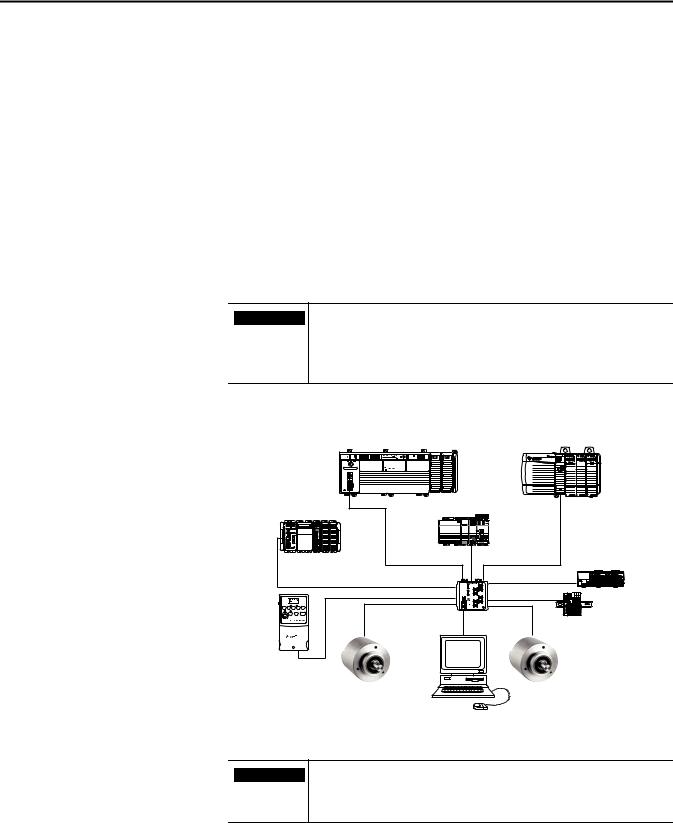
Star topology
The star structure consists of a number of devices connected to a central switch.
IMPORTANT When this topology is used, make the ethernet connection on the 842E encoder to the Link 1 connection. The Link 2 ethernet connection must remain unused.
10 |
Rockwell Automation Publication 842E-UM001A-EN-P May 2012 |
EtherNet/IP overview |
Chapter 3 |
|
|
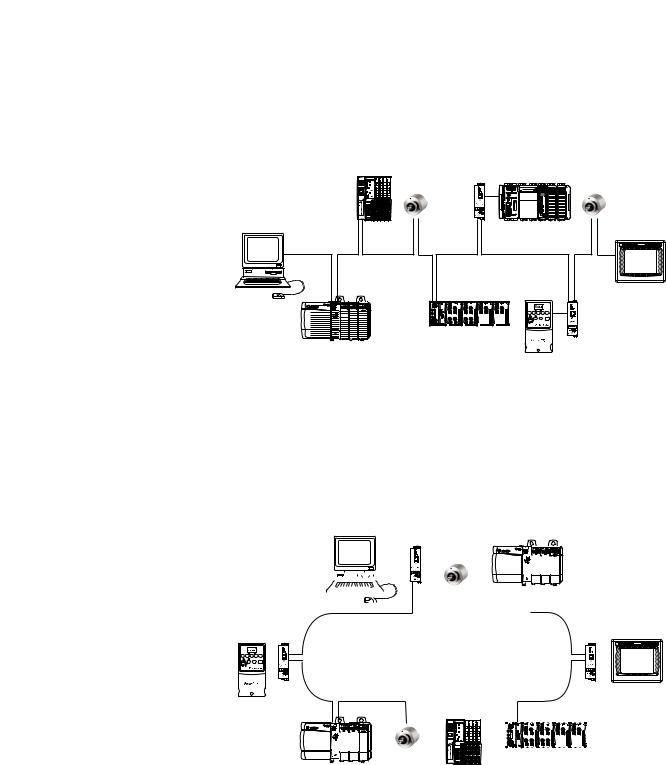
Linear topology
The linear topology uses the embedded switching capability to form a daisychain style network that has a beginning and an end. Linear topology simplifies installation and reduces wiring and installation costs, but a break in the network disconnects all devices downstream from the break. When this topology is used, both ethernet connections on the encoder may be used. For the network connection use Link 1, Link 2, or both.
Device level ring topology
A DLR network is a single-fault-tolerant ring network intended for the interconnection of automation devices. DLR topology is advantageous as it can tolerate a a break in the network. If a break is detected, the signals are sent out in both directions. With this topology, use both the Link 1 and Link 2 ethernet connections on the 842E encoder.
|
|
|
|
|
|
|
|
|
|
|
|
|
|
|
|
|
|
|
|
|
|
|
|
|
|
|
|
|
|
|
|
|
|
|
|
|
|
|
|
|
|
|
|
|
|
|
|
|
|
|
|
|
|
|
|
|
|
|
|
|
|
|
|
|
|
|
|
|
|
|
|
|
|
|
|
|
|
|
|
|
|
|
|
|
|
|
|
|
|
|
|
|
|
|
|
|
|
|
|
|
|
|
|
|
|
|
|
|
|
|
|
|
|
|
|
|
|
|
|
|
|
|
|
|
|
|
|
|
|
|
|
|
|
|
|
|
|
|
|
|
|
|
|
|
|
|
|
|
|
|
|
|
|
|
|
|
|
|
|
|
|
|
|
|
|
|
|
|
|
|
|
|
|
|
|
|
|
|
|
|
|
|
|
|
|
|
|
|
|
|
|
|
|
|
|
|
|
|
|
|
|
|
|
|
|
|
|
|
|
|
|
|
|
|
|
|
|
|
|
|
|
|
|
|
|
|
|
|
|
|
|
|
|
|
|
|
|
|
|
|
|
|
|
|
|
|
|
|
|
|
|
|
|
|
|
|
|
|
|
|
|
|
|
|
|
|
|
|
|
|
|
|
|
|
|
|
|
|
|
|
|
|
|
|
|
|
|
|
|
|
|
|
|
|
|
|
|
|
|
|
|
|
|
|
|
|
|
|
|
|
|
|
|
|
|
|
|
|
|
|
|
|
|
|
|
|
|
|
|
|
|
|
|
|
|
|
|
|
|
|
|
|
|
|
|
|
|
|
|
|
|
|
|
|
|
|
|
|
|
|
|
|
|
|
|
|
|
|
|
|
|
|
|
|
|
|
|
|
|
|
|
|
|
|
|
|
|
|
|
|
|
|
|
|
|
|
|
|
|
|
|
|
|
|
|
|
|
|
|
|
|
|
|
|
|
|
|
|
|
|
|
|
|
|
|
|
|
|
|
|
|
|
|
|
|
|
|
|
|
|
|
|
|
|
|
|
|
|
|
|
|
|
|
|
|
|
|
|
|
|
|
|
|
|
|
|
|
|
|
|
|
|
|
|
|
|
|
|
|
|
|
|
|
|
|
|
|
|
|
|
|
|
|
|
|
|
|
|
|
|
|
|
|
|
|
|
|
|
|
|
|
|
|
|
|
|
|
|
|
|
|
|
|
|
|
|
|
|
|
|
|
|
|
|
|
|
|
|
|
|
|
|
|
|
|
|
|
|
|
|
|
|
|
|
|
|
|
|
|
|
|
|
|
|
|
|
|
|
|
|
|
|
|
|
|
|
|
|
|
|
|
|
|
|
|
|
|
|
|
|
|
|
|
|
|
|
|
|
|
|
|
|
|
|
|
|
|
|
|
|
|
|
|
|
|
|
|
|
|
|
|
|
|
|
|
|
|
|
|
|
|
|
|
|
|
|
|
|
|
|
|
|
|
|
|
|
|
|
|
|
|
|
|
|
|
|
|
|
|
|
|
|
|
|
|
|
|
|
|
|
|
|
|
|
|
|
|
|
|
|
|
|
|
|
|
|
|
|
|
|
|
|
|
|
|
|
|
|
|
|
|
|
|
|
|
|
|
|
|
|
|
|
|
|
|
|
|
|
|
|
|
|
|
|
|
|
|
|
|
|
|
|
|
|
|
|
|
|
|
|
|
|
|
|
|
|
|
|
|
|
|
|
|
|
|
|
|
|
|
|
|
|
|
|
|
|
|
|
|
|
|
|
|
|
|
|
|
|
|
|
|
|
|
|
|
|
|
|
|
|
|
|
|
|
|
|
|
|
|
|
|
|
|
|
|
|
|
|
|
|
|
|
|
|
|
|
|
|
|
|
|
|
|
|
|
|
|
|
|
|
|
|
|
|
|
|
|
|
|
|
|
|
|
|
|
|
|
|
|
|
|
|
|
|
|
|
|
|
|
|
|
|
|
|
|
|
|
|
|
|
|
|
|
|
|
|
|
|
|
|
|
|
|
|
|
|
|
|
|
|
|
|
|
|
|
|
|
|
|
|
|
|
|
|
|
|
|
|
|
|
|
|
|
|
|
|
|
|
|
|
|
|
|
|
|
|
|
|
|
|
|
|
|
|
|
|
|
Rockwell Automation Publication 842E-UM001A-EN-P May 2012 |
11 |
|||||||||||||||||||||||||||||||||||||||||||||||||||||||||||||||||

Chapter 3 EtherNet/IP overview
CIP object model
EtherNet/IP uses an object model for network communication wherein all functions and data of a device are defined. The important terms are as follows:
Class: A class contains related objects of a device, organized in instances.
Instance: An instance consists of different attributes that describe the properties of the instance. Different instances of a class have the same services, the same behavior, and the same attributes. They can, however, have different values.
Attribute: The attributes represent the data a device provides over EtherNet/IP. These include the current values of, for example, a configuration or an input. Typical attributes are configuration and status information.
Service: Services are used to access classes or the attributes of a class or to generate specific events. These services execute defined actions such as reading the attributes.
The following table shows an example of the object model for the 842E encoders.
Class |
Instance |
Attribute |
Value |
|
|
|
|
842E |
Basic |
Resolution per revolution |
15 bit |
|
|
Revolutions, total |
12 bit |
|
Advanced |
Resolution per revolution |
18 bit |
|
|
Revolutions, total |
12 bit |
The 842E EtherNet/IP encoder supports the following classes of the encoder profile:
Supported classes
|
|
|
Number of |
Class code |
Object class |
Description |
instances |
|
|
|
|
0x01 |
Identity object |
Contains information on the node within the network |
1 |
|
|
|
|
0x02 |
Message router object |
Processes all messages and routes them to the |
1 |
appropriate objects |
|
||
|
|
||
|
Assembly object |
Assembles attributes (data) of various objects to a |
7 |
|
single object |
|
|
0x04 |
(I/O-assembly class) |
|
|
Used for I/O messages |
|
||
|
|
|
|
0x06 |
Connection manager object |
Contains connection specific attributes for triggering, |
1 |
transport, and connection type |
|
||
|
|
||
0x23 |
Position sensor object |
Administrates device specific data like position and |
1 |
counting direction |
|
||
|
|
||
0x47 |
Device level ring (DLR) object |
Contains the configuration and status information of |
1 |
the DLR protocol |
|
||
|
|
||
0x48 |
QoS object |
Contains mechanisms used to treat traffic streams with |
1 |
different relative priorities |
|
||
|
|
||
0xF4 |
Port object |
Contains implemented port types port numbers and |
1 |
port names |
|
||
|
|
||
|
TCP/IP interface object |
Contains all attributes for configuring the TCP/IP |
1 |
0xF5 |
interface |
|
|
|
|
||
|
|
|
|
0xF6 |
Ethernet link object |
Contains connection-specific attributes like |
3 |
transmission rate, MAC address, or duplex mode |
|
||
|
|
12 |
Rockwell Automation Publication 842E-UM001A-EN-P May 2012 |
EtherNet/IP overview |
Chapter 3 |
|
|
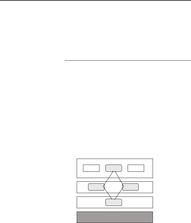
23h Position sensor |
01h Identity |
|
02h Message |
|
router |
04h Assembly |
|
|
F4h |
|
F5h |
|
F6h |
|
Network |
|
06h Connection manager |
The Class Instance Attributes for the position sensor object are provided in the tables below.
See Appendix B on page 53 for an example of how to create an explicit message in
RSLogix 5000 using the position sensor object tables.
Class services of the position sensor object
Instance |
Service Name |
Description |
|
|
|
0x05 |
Reset |
Reboot with all EEProm parameters of the encoder, reboot with the factory |
|
|
defaults |
|
|
00: reboot Object– read all EEProm parameters |
|
|
01: set and save factory defaults and reboot object– read all EEProm parameter |
0x0E |
Get_Attribute_Single |
Returns value of attribute |
|
|
|
0x15 |
Restore |
Restore all parameter values from the non-volatile storage, customer defaults |
(21dec) |
|
|
0x16 |
Save |
Save parameters to the non-volatile storage |
(22dec) |
|
|
Rockwell Automation Publication 842E-UM001A-EN-P May 2012 |
13 |

Chapter 3 EtherNet/IP overview
Class attributes of the position sensor object
Num |
Required/ |
Access |
|
|
|
|
|
(dec) |
optional |
rule |
Name |
Data type |
Description |
Default |
|
|
|
|
|
|
|
|
|
1 |
Required |
Get |
Revision |
INT |
Object revision no |
0x00 02 |
|
|
(implemented) |
|
|
|
|
|
|
2 |
Implemented |
Get |
Max instance |
INT |
Max. instance number of an object |
0x00 |
01 |
|
|
|
|
|
in this class |
|
|
3 |
Implemented |
Get |
Number of |
INT |
Number of object instances in this |
0x00 |
01 |
|
|
|
instances |
|
class |
|
|
6 |
Implemented |
Get |
Maximum ID |
INT |
Highest implemented class ID |
0x00 |
64 |
|
|
|
number class |
|
|
|
|
|
|
|
attributes |
|
|
|
|
7 |
Implemented |
Get |
Maximum ID |
INT |
Highest implemented instance |
0x00 |
7A |
|
|
|
number |
|
attribute ID |
|
|
|
|
|
instance |
|
|
|
|
|
|
|
attributes |
|
|
|
|
100 |
Get |
NV (1) |
Encoder |
ARRAY |
aa.bb: major revision |
842eaa.bb |
|
|
|
|
firmware |
of bytes |
minor revision |
dd.mm.yy |
|
|
|
|
version |
dd.mm.yy: day.month.year |
|
|
|
|
|
|
|
|
|
||
(1) Nonvolatile
Instance Services of the position sensor object are automatically populated in the explicit message instruction configuration
Instance services of the position sensor object
Instance |
Service name |
Description |
|
|
|
0x0E |
Get_Attribute_Single |
Returns value of attribute |
|
|
|
0x10 |
Set_Attribute_Single |
Sets value of attribute |
|
|
|
1Instance attributes of the position sensor object
Attribute ID |
Attribute ID |
Access |
NV / |
|
|
|
Min. / max |
(dec) |
(hex) |
rule (1) |
V (2) |
Name |
Data type |
Description |
(default) |
1 |
1 |
Get |
V |
Number of attributes |
INT |
Number of supported attributes in this |
0x0039 |
|
|
|
|
|
|
class |
|
2 |
2 |
Get |
V |
Attribute list |
ARRAY |
List of supported attributes |
– |
|
|
|
|
|
of byte |
|
|
10 |
A |
Get |
V |
Position value signed |
DINT |
Current position value (32 Bit) |
none |
|
|
|
|
|
|
|
|
11 |
B |
Get |
NV |
Position sensor type |
INT |
Device Type |
Min 0x00 01 |
|
|
|
|
(see following table, encoder ID) |
|
0x01: Single-turn absolute encoder |
Max 0x00 02 |
|
|
|
|
|
|
0x02: Multi-turn absolute encoder |
(0x00 02) |
12 |
C |
Set |
NV |
Direction counting toggle, code |
BOOL |
Definition of direction of incrementing |
(0: CW) |
|
|
|
|
sequence (CS) |
|
counts (10) |
|
|
|
|
|
|
|
0: CW |
|
|
|
|
|
|
|
1:CCW |
|
13 |
D |
Set |
NV |
Commissioning diagnostic control |
BOOL |
ON: 1 Encoder diagnostics possible |
(OFF: 0) |
|
|
|
|
(encoder position test) |
|
OFF: 0 No diagnostics implemented |
|
14 |
E |
Set |
NV |
Scaling function control (SFC) |
BOOL |
ON: 1 calc. value (from 16+42) |
(OFF: 0) |
|
|
|
|
|
|
OFF: 0 phys. resolution [steps] |
|
15 |
F |
Set |
NV |
Position format |
ENG |
Format of position value |
(0x1001) |
|
|
|
|
|
UNIT |
(e.g., arcsec or steps) |
|
|
|
|
|
|
|
Engineering unit: 0x1001 (counts) |
|
14 |
Rockwell Automation Publication 842E-UM001A-EN-P May 2012 |

|
|
|
|
|
|
|
EtherNet/IP overview |
Chapter 3 |
|
|
|
|
|
|
|
|
|
|
|
|
|
|
|
|
|
|
|
|
|
|
Attribute ID |
Attribute ID |
Access |
NV / |
|
|
|
Min. / max |
|
|
(dec) |
(hex) |
rule (1) |
V (2) |
Name |
Data type |
Description |
(default) |
|
|
16 |
10 |
Set |
NV |
Counts per range |
DINT |
Number of requested steps per |
Min 0x00 00 00 01 |
|
|
|
|
|
|
|
|
revolution. |
Max 0x00 04 00 00 |
|
|
|
|
|
|
|
|
|
(0x00 04 00 00) |
|
|
17 |
11 |
Set |
NV |
Total measuring range |
DINT |
Total resolution |
Min / Max |
|
|
|
|
|
|
|
|
|
0x00 00 00 01 / |
|
|
|
|
|
|
|
|
|
Max. 2^n * Attr.16 (Max. |
|
|
|
|
|
|
|
|
|
2^n * Attr.16) |
|
|
18 |
12 |
Set |
NV |
Position measuring increment |
DINT |
Minimum resolution in steps (is always |
(0x00 00 00 01) |
|
|
|
|
|
|
|
|
0x00 01) |
|
|
|
19 |
13 |
Set |
NV |
Preset value |
DINT |
The preset value is set to the current |
Min / Max |
|
|
|
|
|
|
|
|
position value |
0x00 00 00 00 / |
|
|
|
|
|
|
|
|
|
Attr.17 - 1 |
|
|
|
|
|
|
|
|
|
(0x00 00 00 00) |
|
|
21 |
15 |
Get |
V |
Position status register |
BYTE |
State of the software limit switch |
(0x00) |
|
|
|
|
|
|
|
|
Bit 0: Out of range |
|
|
|
|
|
|
|
|
|
Bit 1: Range overflow |
|
|
|
|
|
|
|
|
|
Bit: 2: Range underflow |
|
|
|
|
|
|
|
|
|
Bit 3…7 reserved |
|
|
|
22 |
16 |
Set |
NV |
Position low limit |
DINT |
Lower limit for position |
0x00 00 00 00 |
|
|
|
|
|
|
|
|
|
|
|
23 |
17 |
Set |
NV |
Position high limit |
DINT |
Upper limit for position |
0x3F FF FF FF |
||
|
|
|
|
|
|
|
|
|
|
24 |
18 |
Get |
V |
Velocity value |
DINT |
Current velocity (32 Bit) |
Format (25) und (26) |
||
|
|
|
|
|
|
|
|
|
|
25 |
19 |
Set |
NV |
Velocity format |
ENG |
Format of velocity value |
(0x1F0F) |
|
|
|
|
|
|
|
|
INT |
0x1F04 counts/s |
|
|
|
|
|
|
|
|
|
0x1F0E revs/s |
|
|
|
|
|
|
|
|
|
0x1F0F revs/min |
|
|
|
26 |
1A |
Set |
NV |
Velocity resolution |
DINT |
Minimum resolution of velocity value |
(0x00 00 00 01) |
|
|
|
|
|
|
|
|
(24) |
|
|
|
27 |
1B |
Set |
NV |
Minimum velocity setpoint |
DINT |
Minimum velocity set-point for setting |
(0x00 00 00 00) |
|
|
|
|
|
|
|
|
warning flag (47) |
|
|
|
28 |
1C |
Set |
NV |
Maximum velocity setpoint |
DINT |
Maximum velocity set-point for setting |
(0x3F FF FF FF) |
|
|
|
|
|
|
|
|
warning flag (47) |
|
|
|
29 |
1D |
Get |
V |
Acceleration value |
DINT |
Current acceleration (32 Bit) |
Format (30) und (31) |
|
|
|
|
|
|
|
|
|
|
|
30 |
1E |
Set |
NV |
Acceleration format |
ENG |
Format of acceleration value |
(0x0810) |
|
|
|
|
|
|
|
|
UNIT |
0x0810: cps/s |
|
|
|
|
|
|
|
|
|
0x0811: rpm/s |
|
|
|
|
|
|
|
|
|
0x0812: rps/s |
|
|
|
31 |
1F |
Set |
NV |
Acceleration resolution |
DINT |
Minimum resolution of acceleration |
(0x00 00 00 01) |
|
|
|
|
|
|
|
|
value |
|
|
|
32 |
20 |
Set |
NV |
Minimum acceleration setpoint |
DINT |
Minimum acceleration set-point |
(0x00 00 00 00) |
|
|
|
|
|
|
|
|
|
|
|
33 |
21 |
Set |
NV |
Maximum acceleration setpoint |
DINT |
Maximum acceleration set-point |
0x3F FF FF FF |
||
|
|
|
|
|
|
|
|
|
|
41 |
29 |
Get |
V |
Operating status |
BYTE |
Operating status encoder |
|
|
|
|
|
|
|
|
|
|
Bit 0: Direct. 0 (inc.) 1 (dec.) |
|
|
|
|
|
|
|
|
|
Bit 1: Scaling 0 (off) 1 (on) |
|
|
|
|
|
|
|
|
|
Bit: 2…4 Reserved |
|
|
|
|
|
|
|
|
|
Bit: 5: Diag. 0 (off) 1 (on) |
|
|
|
|
|
|
|
|
|
Bit 6…7 manuf. spec. |
|
|
|
42 |
2A |
Get |
NV |
Physical resolution span (PRS) |
DINT |
Number of steps per rev |
(0x00 04 00 00) |
|
|
|
|
|
|
|
|
Basic = 15 bit |
|
|
|
|
|
|
|
|
|
Advanced = 18 bit |
|
|
|
|
|
|
|
|
|
(single-turn part) |
|
|
|
43 |
2B |
Get |
NV |
Physical resolution |
INT |
Number of revolutions |
(0x00 01) single |
|
|
|
|
|
|
number of spans |
|
(multi-turn part) |
(0x10 00) multi |
|
|
|
|
|
|
|
|
|
|
|
44 |
2C |
Get |
V |
Alarms |
WORD |
Flags for alarms (errors) |
|
|
|
|
|
|
|
|
|
|
|
|
|
45 |
2D |
Get |
NV |
Supported alarms |
WORD |
Information on supported alarms |
0x3003 |
|
|
|
|
|
|
|
|
|
|
|
|
46 |
2E |
Get |
V |
Alarm flag |
BOOL |
Indication of set alarm |
0: OK |
|
|
|
|
|
|
|
|
|
|
1: Alarm error |
|
|
47 |
2F |
Get |
V |
Warnings |
WORD |
Flags for warnings |
|
|
|
|
|
|
|
|
|
|
|
|
48 |
30 |
Get |
NV |
Supported warnings |
WORD |
Information on supported warnings |
0x673C |
|
|
|
|
|
|
|
|
|
|
|
|
Rockwell Automation Publication 842E-UM001A-EN-P May 2012 |
15 |

Chapter 3 |
EtherNet/IP overview |
|
|
|
|
|
||
|
|
|
|
|
|
|
|
|
|
|
|
|
|
|
|
|
|
|
Attribute ID |
Attribute ID |
Access |
NV / |
|
|
|
Min. / max |
|
(dec) |
(hex) |
rule (1) |
V (2) |
Name |
Data type |
Description |
(default) |
|
49 |
31 |
Get |
V |
Warning flag |
BOOL |
Indication of set warning |
0: OK |
|
|
|
|
|
|
|
|
1: Warning Flag |
|
50 |
32 |
Get |
NV |
Operating time |
DINT |
Storage of operating time counter |
0 |
|
|
|
|
|
|
|
[0,1h], the format of the counter is |
|
|
|
|
|
|
|
|
second. |
|
|
51 |
33 |
Get |
NV |
Offset value |
DINT |
Offset value is calculated when using |
0x00 00 00 00 |
|
|
|
|
|
|
|
preset function |
|
|
100 |
64 |
Get |
V |
Temperature value |
INT |
Current temperature value |
0xF0 60 |
|
|
|
|
|
|
|
-40…100°C or -40…212°F |
0x27 10 |
|
|
|
|
|
|
|
Accuracy of the temperature sensor is |
(-4000… +10000) |
|
|
|
|
|
|
|
about +/- 5 °C. |
|
|
101 |
65 |
Set |
NV |
Temperature value format |
ENG |
Format of temperature value |
(0x1200) |
|
|
|
|
|
|
UNIT |
°C or °F (Fahrenheit) |
|
|
|
|
|
|
|
|
0x1200: °C |
|
|
|
|
|
|
|
|
0x1201: °F |
|
|
102 |
66 |
Set |
NV |
Temperature resolution |
DINT |
Minimum resolution of temperature |
(0x00000001) |
|
|
|
|
|
|
|
value |
|
|
|
|
|
|
|
|
[°C/100] or [(°F)/100] |
|
|
103 |
67 |
Set |
NV |
Minimum temperature value |
INT |
Minimum temperature set-point |
0xF0 60 |
|
|
|
|
|
setpoint |
|
(-40…100°C, -40…212°F) |
(-4000) |
|
|
|
|
|
|
|
|
|
104 |
68 |
Set |
NV |
Maximum temperature value |
INT |
Maximum temperature set-point |
0x27 10 (+10000) |
|
|
|
|
|
|
setpoint |
|
(-40…100°C, -40…212°F) |
or 0x52D0 |
|
|
|
|
|
|
|
|
(+21200) |
|
105 |
69 |
Get |
V |
Fault header |
DINT |
Flags of encoder sensor errors and |
0x00 00 00 00 |
|
|
|
|
|
(see Sensor error table) |
|
warnings |
|
|
|
|
|
|
|
|
|
|
106 |
6A |
Set |
NV |
Slave sign of live |
DINT |
Flags for encoder functionalities |
0x0000500 |
|
|
|
|
|
|
|
|
(Bit-field): |
|
|
|
|
|
|
|
|
Bit 0: Slave sign of live (on/off) |
|
|
|
|
|
|
|
|
Bit 1…7: not used |
|
|
|
|
|
|
|
|
Bit 8…15: UpdateFactor (1…127) |
|
|
|
|
|
|
|
|
Bit 16…31: not used |
|
|
107 |
6B |
Get |
NV |
Encoder motion time |
DINT |
Storage of the motion time. This counter |
0 |
|
|
|
|
|
|
|
is incrementing if the encoder is in |
|
|
|
|
|
|
|
|
rotation [sec]. |
|
|
108 |
6C |
Get |
NV |
Encoder operating time [second] |
DINT |
Storage of the operating time. This |
0 |
|
|
|
|
|
|
|
counter is incrementing if the encoder is |
|
|
|
|
|
|
|
|
powered on [sec]. |
|
|
109 |
6D |
Get |
NV |
Max velocity |
DINT |
Storage of the maximum velocity of the |
0 |
|
|
|
|
|
RA [cnts/ms] |
|
encoder in operational state. |
|
|
110 |
6E |
Get |
NV |
Max acceleration [cnts/(ms)2] |
DINT |
Storage of the maximum acceleration of |
0 |
|
|
|
|
|
|
|
the encoder in operational state. |
|
|
111 |
6F |
Get |
NV |
Max temp [°C/100] |
DINT |
Storage of the maximum temperature of |
2000 |
|
|
|
|
|
|
|
the encoder in operational state |
|
|
112 |
70 |
Get |
NV |
Min temp [°C/100] |
DINT |
Storage of the minimum temperature of |
2000 |
|
|
|
|
|
|
|
the encoder in operational state |
|
|
113 |
71 |
Get |
NV |
Number of startups |
DINT |
Storage of the number of startups |
0 |
|
|
|
|
|
|
|
(power-on) cycles |
|
|
114 |
72 |
Get |
V |
LED current value [μA] |
INT |
Current LED current [μA] |
200…25.000 |
|
|
|
|
|
|
|
Range: 200…25.000 |
(0) |
|
115 |
73 |
Get |
NV |
Max current value [μA] |
INT |
Max. LED current [μA] |
1.500 |
|
116 |
74 |
Get |
NV |
Min current value [μA] |
INT |
Min. LED current [μA] |
1.500 |
|
117 |
75 |
Get |
V |
Power supply voltage [mV] |
INT |
Current supply voltage [mV] |
9.500…30.500 |
|
|
|
|
|
Accuracy is about 1% from the |
|
Range: 9.500…30.500 |
(24.000) |
|
|
|
|
|
measurement value. |
|
|
|
(1)You can do a Get of all the Set values, as shown in Appendix B, page 53. It is always good programming practice to do a Get after setting a value to ensure the Set command was successful.
(2)Nonvolatile/volatile
16 |
Rockwell Automation Publication 842E-UM001A-EN-P May 2012 |
Loading...