


 Loading...
User Manual
E3 & E3 Plus Solid-State Overload Relay
Catalog Numbers 193/592-EC1, -EC2, -EC3, -EC5

Important User Information
Solid-state equipment has operational characteristics differing from those of electromechanical equipment. Safety Guidelines for the Application, Installation and Maintenance of Solid State Controls (publication SGI-1.1 available from your local Rockwell Automation sales office or online at http://www.rockwellautomation.com/literature/) describes some important differences between solid-state equipment and hard-wired electromechanical devices. Because of this difference, and also because of the wide variety of uses for solid-state equipment, all persons responsible for applying this equipment must satisfy themselves that each intended application of this equipment is acceptable.
In no event will Rockwell Automation, Inc. be responsible or liable for indirect or consequential damages resulting from the use or application of this equipment.
The examples and diagrams in this manual are included solely for illustrative purposes. Because of the many variables and requirements associated with any particular installation, Rockwell Automation, Inc. cannot assume responsibility or liability for actual use based on the examples and diagrams.
No patent liability is assumed by Rockwell Automation, Inc. with respect to use of information, circuits, equipment, or software described in this manual.
Reproduction of the contents of this manual, in whole or in part, without written permission of Rockwell Automation, Inc., is prohibited.
Throughout this manual, when necessary, we use notes to make you aware of safety considerations.
WARNING: Identifies information about practices or circumstances that can cause an explosion in a hazardous environment, which may lead to personal injury or death, property damage, or economic loss.
ATTENTION: Identifies information about practices or circumstances that can lead to personal injury or death, property damage, or economic loss. Attentions help you identify a hazard, avoid a hazard, and recognize the consequence
SHOCK HAZARD: Labels may be on or inside the equipment, for example, a drive or motor, to alert people that dangerous voltage may be present.
BURN HAZARD: Labels may be on or inside the equipment, for example, a drive or motor, to alert people that surfaces may reach dangerous temperatures.
IMPORTANT Identifies information that is critical for successful application and understanding of the product.
Allen-Bradley, Rockwell Software, Rockwell Automation, and TechConnect are trademarks of Rockwell Automation, Inc.
Trademarks not belonging to Rockwell Automation are property of their respective companies.

|
Table of Contents |
|
|
Manual Objectives . . . . . . . . . . . . . . . . . . . . . . . . . . . . . . . . . . . . . . . . . . . . . . . . |
9 |
|
Who Should Use This Manual . . . . . . . . . . . . . . . . . . . . . . . . . . . . . . . . . . . . . |
9 |
|
Vocabulary. . . . . . . . . . . . . . . . . . . . . . . . . . . . . . . . . . . . . . . . . . . . . . . . . . . . . . . . |
9 |
|
Conventions . . . . . . . . . . . . . . . . . . . . . . . . . . . . . . . . . . . . . . . . . . . . . . . . . . . . . . |
9 |
|
Reference Manuals . . . . . . . . . . . . . . . . . . . . . . . . . . . . . . . . . . . . . . . . . . . . . . . . |
9 |
Product Overview |
Introduction . . . . . . . . . . . . . . . . . . . . . . . . . . . . . . . . . . . . . . . . . . . . . . . . . . . . . |
11 |
|
Description . . . . . . . . . . . . . . . . . . . . . . . . . . . . . . . . . . . . . . . . . . . . . . . . . . . . . . |
11 |
|
Catalog Number Explanation . . . . . . . . . . . . . . . . . . . . . . . . . . . . . . . . . . . . . |
12 |
|
Single-/Three-Phase Operation. . . . . . . . . . . . . . . . . . . . . . . . . . . . . . . . . . . . |
12 |
|
Protection & Warning Functions. . . . . . . . . . . . . . . . . . . . . . . . . . . . . . . . . . |
12 |
|
Parameter Monitoring . . . . . . . . . . . . . . . . . . . . . . . . . . . . . . . . . . . . . . . . . . . . |
13 |
|
Current-Based Operational Data . . . . . . . . . . . . . . . . . . . . . . . . . . . . . . |
13 |
|
Diagnostic Parameters . . . . . . . . . . . . . . . . . . . . . . . . . . . . . . . . . . . . . . . . |
13 |
|
Voltage Parameters . . . . . . . . . . . . . . . . . . . . . . . . . . . . . . . . . . . . . . . . . . . |
13 |
|
Power Parameters. . . . . . . . . . . . . . . . . . . . . . . . . . . . . . . . . . . . . . . . . . . . . |
13 |
|
Overload Relay Features . . . . . . . . . . . . . . . . . . . . . . . . . . . . . . . . . . . . . . . . . . |
14 |
|
Trip Relay . . . . . . . . . . . . . . . . . . . . . . . . . . . . . . . . . . . . . . . . . . . . . . . . . . . |
14 |
|
Inputs & Outputs . . . . . . . . . . . . . . . . . . . . . . . . . . . . . . . . . . . . . . . . . . . . |
14 |
|
User Interface . . . . . . . . . . . . . . . . . . . . . . . . . . . . . . . . . . . . . . . . . . . . . . . . |
15 |
|
DeviceNet Compatibility . . . . . . . . . . . . . . . . . . . . . . . . . . . . . . . . . . . . . |
16 |
|
Flash Memory . . . . . . . . . . . . . . . . . . . . . . . . . . . . . . . . . . . . . . . . . . . . . . . . |
16 |
Installation & Wiring |
Introduction . . . . . . . . . . . . . . . . . . . . . . . . . . . . . . . . . . . . . . . . . . . . . . . . . . . . . |
17 |
|
Receiving . . . . . . . . . . . . . . . . . . . . . . . . . . . . . . . . . . . . . . . . . . . . . . . . . . . . . . . . |
17 |
|
Unpacking/Inspecting . . . . . . . . . . . . . . . . . . . . . . . . . . . . . . . . . . . . . . . . . . . . |
17 |
|
Storing . . . . . . . . . . . . . . . . . . . . . . . . . . . . . . . . . . . . . . . . . . . . . . . . . . . . . . . . . . |
17 |
|
General Precautions . . . . . . . . . . . . . . . . . . . . . . . . . . . . . . . . . . . . . . . . . . . . . . |
18 |
|
Starter Assembly . . . . . . . . . . . . . . . . . . . . . . . . . . . . . . . . . . . . . . . . . . . . . . . . . |
18 |
|
Installation. . . . . . . . . . . . . . . . . . . . . . . . . . . . . . . . . . . . . . . . . . . . . . . . . . . |
18 |
|
Approximate Dimensions . . . . . . . . . . . . . . . . . . . . . . . . . . . . . . . . . . . . . |
21 |
|
Separate Panel Adapter . . . . . . . . . . . . . . . . . . . . . . . . . . . . . . . . . . . . . . . . . . . |
24 |
|
Approximate Dimensions . . . . . . . . . . . . . . . . . . . . . . . . . . . . . . . . . . . . . |
24 |
|
Voltage Input Module . . . . . . . . . . . . . . . . . . . . . . . . . . . . . . . . . . . . . . . . . . . . |
26 |
|
Specifications . . . . . . . . . . . . . . . . . . . . . . . . . . . . . . . . . . . . . . . . . . . . . . . . . . . . |
26 |
|
Power Terminals . . . . . . . . . . . . . . . . . . . . . . . . . . . . . . . . . . . . . . . . . . . . . |
26 |
|
Three-Pole Terminal Blocks . . . . . . . . . . . . . . . . . . . . . . . . . . . . . . . . . . . |
27 |
|
Terminal Lug Kits . . . . . . . . . . . . . . . . . . . . . . . . . . . . . . . . . . . . . . . . . . . . |
27 |
|
Control, DeviceNet, & Voltage Input Module Terminals . . . . . . . . |
27 |
|
Terminal Designations. . . . . . . . . . . . . . . . . . . . . . . . . . . . . . . . . . . . . . . . . . . . |
29 |
|
Control Terminals. . . . . . . . . . . . . . . . . . . . . . . . . . . . . . . . . . . . . . . . . . . . |
29 |
|
DeviceNet Terminals . . . . . . . . . . . . . . . . . . . . . . . . . . . . . . . . . . . . . . . . . |
29 |
|
Grounding. . . . . . . . . . . . . . . . . . . . . . . . . . . . . . . . . . . . . . . . . . . . . . . . . . . . . . . |
29 |
|
Short-Circuit Ratings. . . . . . . . . . . . . . . . . . . . . . . . . . . . . . . . . . . . . . . . . . . . . |
30 |
|
Short-Circuit Ratings . . . . . . . . . . . . . . . . . . . . . . . . . . . . . . . . . . . . . . . . . |
30 |
|
High-Fault Short-Circuit Ratings . . . . . . . . . . . . . . . . . . . . . . . . . . . . . . |
31 |
|
Fuse Coordination . . . . . . . . . . . . . . . . . . . . . . . . . . . . . . . . . . . . . . . . . . . . . . . |
32 |
Rockwell Automation Publication 193-UM002I-EN-P - December 2011 |
3 |

Protective Trip & Warning
Functions
Typical Motor Connections. . . . . . . . . . . . . . . . . . . . . . . . . . . . . . . . . . . . . . . 34
Three-Phase Direct On-Line (DOL) & Single-Phase Full Voltage 34
External Line Current Transformer Application . . . . . . . . . . . . . . . . . . . . 34
Specifications . . . . . . . . . . . . . . . . . . . . . . . . . . . . . . . . . . . . . . . . . . . . . . . . 34
Installation Requirements . . . . . . . . . . . . . . . . . . . . . . . . . . . . . . . . . . . . . 35
External Potential Transformer (PT) Connection . . . . . . . . . . . . . . . 36
Core Balanced Ground Fault Sensor Application. . . . . . . . . . . . . . . . 37
Typical Control Circuit. . . . . . . . . . . . . . . . . . . . . . . . . . . . . . . . . . . . . . . . . . . 41
Wiring Diagrams . . . . . . . . . . . . . . . . . . . . . . . . . . . . . . . . . . . . . . . . . . . . . 41
External/Remote Reset (FRN 3.001 & Later) . . . . . . . . . . . . . . . . . . . 44
Introduction . . . . . . . . . . . . . . . . . . . . . . . . . . . . . . . . . . . . . . . . . . . . . . . . . . . . . 45
Trip Enable . . . . . . . . . . . . . . . . . . . . . . . . . . . . . . . . . . . . . . . . . . . . . . . . . . . . . . 45
Warning Enable. . . . . . . . . . . . . . . . . . . . . . . . . . . . . . . . . . . . . . . . . . . . . . . . . . 45
Overload Protection . . . . . . . . . . . . . . . . . . . . . . . . . . . . . . . . . . . . . . . . . . . . . . 45
Overload Trip . . . . . . . . . . . . . . . . . . . . . . . . . . . . . . . . . . . . . . . . . . . . . . . . 45
FLA Setting . . . . . . . . . . . . . . . . . . . . . . . . . . . . . . . . . . . . . . . . . . . . . . . . . . 46
CT Ratio . . . . . . . . . . . . . . . . . . . . . . . . . . . . . . . . . . . . . . . . . . . . . . . . . . . . 47
Trip Class. . . . . . . . . . . . . . . . . . . . . . . . . . . . . . . . . . . . . . . . . . . . . . . . . . . . 47
Trip Curves . . . . . . . . . . . . . . . . . . . . . . . . . . . . . . . . . . . . . . . . . . . . . . . . . . 47
Auto/Manual Reset. . . . . . . . . . . . . . . . . . . . . . . . . . . . . . . . . . . . . . . . . . . 49
Overload Warning. . . . . . . . . . . . . . . . . . . . . . . . . . . . . . . . . . . . . . . . . . . . 50
Overload Diagnostics . . . . . . . . . . . . . . . . . . . . . . . . . . . . . . . . . . . . . . . . . 51
Non-Volatile Thermal Memory. . . . . . . . . . . . . . . . . . . . . . . . . . . . . . . . 51
Phase Loss Protection. . . . . . . . . . . . . . . . . . . . . . . . . . . . . . . . . . . . . . . . . . . . . 51
Phase Loss Trip. . . . . . . . . . . . . . . . . . . . . . . . . . . . . . . . . . . . . . . . . . . . . . . 51
Ground Fault Protection (E3 Plus) . . . . . . . . . . . . . . . . . . . . . . . . . . . . . . . . 52
Ground Fault Setting Range . . . . . . . . . . . . . . . . . . . . . . . . . . . . . . . . . . . 53
Ground Fault Trip. . . . . . . . . . . . . . . . . . . . . . . . . . . . . . . . . . . . . . . . . . . . 53
Ground Fault Trip Inhibit . . . . . . . . . . . . . . . . . . . . . . . . . . . . . . . . . . . . 54
Ground Fault Warning . . . . . . . . . . . . . . . . . . . . . . . . . . . . . . . . . . . . . . . 55
Ground Fault Filter . . . . . . . . . . . . . . . . . . . . . . . . . . . . . . . . . . . . . . . . . . . 55
Stall Protection . . . . . . . . . . . . . . . . . . . . . . . . . . . . . . . . . . . . . . . . . . . . . . . . . . 56
Stall Time. . . . . . . . . . . . . . . . . . . . . . . . . . . . . . . . . . . . . . . . . . . . . . . . . . . . 56
Jam Protection (High Overload). . . . . . . . . . . . . . . . . . . . . . . . . . . . . . . . . . . 57
Jam Trip . . . . . . . . . . . . . . . . . . . . . . . . . . . . . . . . . . . . . . . . . . . . . . . . . . . . . 57
Jam Warning . . . . . . . . . . . . . . . . . . . . . . . . . . . . . . . . . . . . . . . . . . . . . . . . . 58
Underload Protection . . . . . . . . . . . . . . . . . . . . . . . . . . . . . . . . . . . . . . . . . . . . 58
Underload Trip . . . . . . . . . . . . . . . . . . . . . . . . . . . . . . . . . . . . . . . . . . . . . . 58
Underload Warning . . . . . . . . . . . . . . . . . . . . . . . . . . . . . . . . . . . . . . . . . . 59
PTC Trip . . . . . . . . . . . . . . . . . . . . . . . . . . . . . . . . . . . . . . . . . . . . . . . . . . . . 61
PTC Warning. . . . . . . . . . . . . . . . . . . . . . . . . . . . . . . . . . . . . . . . . . . . . . . . 62
Current Imbalance Protection. . . . . . . . . . . . . . . . . . . . . . . . . . . . . . . . . . . . . 62
Current Imbalance Trip. . . . . . . . . . . . . . . . . . . . . . . . . . . . . . . . . . . . . . . 62
Current Imbalance Warning . . . . . . . . . . . . . . . . . . . . . . . . . . . . . . . . . . 63
Communication Fault Protection . . . . . . . . . . . . . . . . . . . . . . . . . . . . . . . . . 64
4 |
Rockwell Automation Publication 193-UM002I-EN-P - December 2011 |

Comm Fault Trip . . . . . . . . . . . . . . . . . . . . . . . . . . . . . . . . . . . . . . . . . . . . 64
Comm Fault Warning . . . . . . . . . . . . . . . . . . . . . . . . . . . . . . . . . . . . . . . . 65
Communication Idle Protection. . . . . . . . . . . . . . . . . . . . . . . . . . . . . . . . . . . 65
Comm Idle Trip. . . . . . . . . . . . . . . . . . . . . . . . . . . . . . . . . . . . . . . . . . . . . . 65
Comm Idle Warning. . . . . . . . . . . . . . . . . . . . . . . . . . . . . . . . . . . . . . . . . . 66
Remote Trip . . . . . . . . . . . . . . . . . . . . . . . . . . . . . . . . . . . . . . . . . . . . . . . . . 66
Voltage Protection . . . . . . . . . . . . . . . . . . . . . . . . . . . . . . . . . . . . . . . . . . . . . . . 67
Under Voltage (UV) Trip . . . . . . . . . . . . . . . . . . . . . . . . . . . . . . . . . . . . . 67
Under Voltage (UV) Warning . . . . . . . . . . . . . . . . . . . . . . . . . . . . . . . . . 68
Over Voltage (OV) Trip . . . . . . . . . . . . . . . . . . . . . . . . . . . . . . . . . . . . . . 68
Over Voltage (OV) Warning . . . . . . . . . . . . . . . . . . . . . . . . . . . . . . . . . . 69
Voltage Unbalance Protection. . . . . . . . . . . . . . . . . . . . . . . . . . . . . . . . . . . . . 69
Voltage Unbalance Trip. . . . . . . . . . . . . . . . . . . . . . . . . . . . . . . . . . . . . . . 69
Voltage Unbalance Warning. . . . . . . . . . . . . . . . . . . . . . . . . . . . . . . . . . . 70
Voltage Rotation Protection. . . . . . . . . . . . . . . . . . . . . . . . . . . . . . . . . . . . . . . 71
Voltage Rotation Trip . . . . . . . . . . . . . . . . . . . . . . . . . . . . . . . . . . . . . . . . 71
Voltage Rotation Warning . . . . . . . . . . . . . . . . . . . . . . . . . . . . . . . . . . . . 71
Frequency Protection . . . . . . . . . . . . . . . . . . . . . . . . . . . . . . . . . . . . . . . . . . . . . 72
Under Frequency (UF) Trip. . . . . . . . . . . . . . . . . . . . . . . . . . . . . . . . . . . 72
Under Frequency Warning . . . . . . . . . . . . . . . . . . . . . . . . . . . . . . . . . . . . 72
Over Frequency (OF) Trip . . . . . . . . . . . . . . . . . . . . . . . . . . . . . . . . . . . . 73
Over Frequency (OF) Warning . . . . . . . . . . . . . . . . . . . . . . . . . . . . . . . . 73
Voltage Input Module Detection . . . . . . . . . . . . . . . . . . . . . . . . . . . . . . . . . . 74
Voltage Hardware Trip . . . . . . . . . . . . . . . . . . . . . . . . . . . . . . . . . . . . . . . 74
Voltage Hardware Warning . . . . . . . . . . . . . . . . . . . . . . . . . . . . . . . . . . . 74
Real Power (kW) Protection . . . . . . . . . . . . . . . . . . . . . . . . . . . . . . . . . . . . . . 75
Under Real Power Trip . . . . . . . . . . . . . . . . . . . . . . . . . . . . . . . . . . . . . . . 75
Under Real Power Warning . . . . . . . . . . . . . . . . . . . . . . . . . . . . . . . . . . . 75
Over Real Power Trip. . . . . . . . . . . . . . . . . . . . . . . . . . . . . . . . . . . . . . . . . 76
Over Real Power Warning. . . . . . . . . . . . . . . . . . . . . . . . . . . . . . . . . . . . . 76
Reactive Power (kVAR) Protection . . . . . . . . . . . . . . . . . . . . . . . . . . . . . . . . 77
Under Reactive Power Consumed Trip. . . . . . . . . . . . . . . . . . . . . . . . . 77
Under Reactive Power Consumed Warning . . . . . . . . . . . . . . . . . . . . 78
Over Reactive Power Consumed Trip . . . . . . . . . . . . . . . . . . . . . . . . . . 78
Over Reactive Power Consumed Warning . . . . . . . . . . . . . . . . . . . . . . 79
Under Reactive Power Generated Trip . . . . . . . . . . . . . . . . . . . . . . . . . 79
Under Reactive Power Generated Warning . . . . . . . . . . . . . . . . . . . . . 80
Over Reactive Power Generated Trip. . . . . . . . . . . . . . . . . . . . . . . . . . . 80
Over Reactive Power Generated Warning . . . . . . . . . . . . . . . . . . . . . . 81
Apparent Power (kVA) Protection. . . . . . . . . . . . . . . . . . . . . . . . . . . . . . . . . 81
Under Apparent Power Trip . . . . . . . . . . . . . . . . . . . . . . . . . . . . . . . . . . 82
Under Apparent Power Warning . . . . . . . . . . . . . . . . . . . . . . . . . . . . . . 82
Over Apparent Power Trip . . . . . . . . . . . . . . . . . . . . . . . . . . . . . . . . . . . . 83
Over Apparent Power Warning. . . . . . . . . . . . . . . . . . . . . . . . . . . . . . . . 83
Power Factor Protection . . . . . . . . . . . . . . . . . . . . . . . . . . . . . . . . . . . . . . . . . . 84
Under Power Factor Lagging Trip . . . . . . . . . . . . . . . . . . . . . . . . . . . . . 84
Rockwell Automation Publication 193-UM002I-EN-P - December 2011 |
5 |

|
Under Power Factor Lagging Warning . . . . . . . . . . . . . . . . . . . . . . . . |
. 85 |
|
Over Power Factor Lagging Trip . . . . . . . . . . . . . . . . . . . . . . . . . . . . . . . |
85 |
|
Over Power Factor Lagging Warning. . . . . . . . . . . . . . . . . . . . . . . . . . . |
86 |
|
Under Power Factor Leading Trip . . . . . . . . . . . . . . . . . . . . . . . . . . . . . |
86 |
|
Under Power Factor Leading Warning . . . . . . . . . . . . . . . . . . . . . . . . . |
87 |
|
Over Power Factor Leading Trip. . . . . . . . . . . . . . . . . . . . . . . . . . . . . . . |
87 |
|
Over Power Factor Leading Warning. . . . . . . . . . . . . . . . . . . . . . . . . . . |
88 |
|
Protective Trip & Warning Summary . . . . . . . . . . . . . . . . . . . . . . . . . . . . . . |
88 |
|
Preventive Maintenance Diagnostics (E3 Overload Relays Series C & |
|
|
Later) . . . . . . . . . . . . . . . . . . . . . . . . . . . . . . . . . . . . . . . . . . . . . . . . . . . . . . . . . . . |
91 |
|
Monitoring . . . . . . . . . . . . . . . . . . . . . . . . . . . . . . . . . . . . . . . . . . . . . . . . . . |
91 |
|
Start Inhibit. . . . . . . . . . . . . . . . . . . . . . . . . . . . . . . . . . . . . . . . . . . . . . . . . . |
91 |
|
Start Inhibit Trip . . . . . . . . . . . . . . . . . . . . . . . . . . . . . . . . . . . . . . . . . . . . . |
91 |
|
Preventive Maintenance Flags . . . . . . . . . . . . . . . . . . . . . . . . . . . . . . . . . |
92 |
|
Queue Clearing. . . . . . . . . . . . . . . . . . . . . . . . . . . . . . . . . . . . . . . . . . . . . . . |
93 |
DeviceNet™ Node |
Introduction . . . . . . . . . . . . . . . . . . . . . . . . . . . . . . . . . . . . . . . . . . . . . . . . . . . . . |
95 |
Commissioning |
Setting the Hardware Switches (Series B & Later) . . . . . . . . . . . . . . . |
95 |
|
Using RSNetWorx for DeviceNet. . . . . . . . . . . . . . . . . . . . . . . . . . . . . . |
96 |
|
Commissioning the Protection Functions . . . . . . . . . . . . . . . . . . . . . . . . . |
103 |
Programmable Parameters |
Introduction . . . . . . . . . . . . . . . . . . . . . . . . . . . . . . . . . . . . . . . . . . . . . . . . . . . . |
105 |
|
Programming . . . . . . . . . . . . . . . . . . . . . . . . . . . . . . . . . . . . . . . . . . . . . . . . . . . |
105 |
|
Program Lock . . . . . . . . . . . . . . . . . . . . . . . . . . . . . . . . . . . . . . . . . . . . . . . |
105 |
|
Reset to Default Factory Settings. . . . . . . . . . . . . . . . . . . . . . . . . . . . . . |
105 |
|
Parameter Group Listing. . . . . . . . . . . . . . . . . . . . . . . . . . . . . . . . . . . . . . . . . |
105 |
|
Overload Setup Group . . . . . . . . . . . . . . . . . . . . . . . . . . . . . . . . . . . . . . . |
111 |
|
Advanced Setup Group . . . . . . . . . . . . . . . . . . . . . . . . . . . . . . . . . . . . . . |
114 |
|
Reset/Lock Group. . . . . . . . . . . . . . . . . . . . . . . . . . . . . . . . . . . . . . . . . . . . . . . |
123 |
|
DeviceNet Setup Group. . . . . . . . . . . . . . . . . . . . . . . . . . . . . . . . . . . . . . |
125 |
|
Output Setup Group. . . . . . . . . . . . . . . . . . . . . . . . . . . . . . . . . . . . . . . . . |
127 |
|
DeviceLogix Group — E3 Plus. . . . . . . . . . . . . . . . . . . . . . . . . . . . . . . . |
131 |
Monitoring Parameters |
Introduction . . . . . . . . . . . . . . . . . . . . . . . . . . . . . . . . . . . . . . . . . . . . . . . . . . . . |
135 |
|
Phase Current Reporting. . . . . . . . . . . . . . . . . . . . . . . . . . . . . . . . . . . . . . . . . |
135 |
|
Current Range . . . . . . . . . . . . . . . . . . . . . . . . . . . . . . . . . . . . . . . . . . . . . . |
135 |
|
Reporting Accuracy. . . . . . . . . . . . . . . . . . . . . . . . . . . . . . . . . . . . . . . . . . |
136 |
|
Ground Fault Current Reporting . . . . . . . . . . . . . . . . . . . . . . . . . . . . . . . . . |
137 |
|
Current Range . . . . . . . . . . . . . . . . . . . . . . . . . . . . . . . . . . . . . . . . . . . . . . |
137 |
|
Frequency Range . . . . . . . . . . . . . . . . . . . . . . . . . . . . . . . . . . . . . . . . . . . . |
137 |
|
Diagnostic Parameters . . . . . . . . . . . . . . . . . . . . . . . . . . . . . . . . . . . . . . . . . . . |
137 |
|
Monitor Group . . . . . . . . . . . . . . . . . . . . . . . . . . . . . . . . . . . . . . . . . . . . . . . . . |
138 |
Voltage Parameters |
Introduction . . . . . . . . . . . . . . . . . . . . . . . . . . . . . . . . . . . . . . . . . . . . . . . . . . . . |
147 |
|
Phase Voltage Reporting . . . . . . . . . . . . . . . . . . . . . . . . . . . . . . . . . . . . . . . . . |
147 |
6 |
Rockwell Automation Publication 193-UM002I-EN-P - December 2011 |

|
Voltage Range . . . . . . . . . . . . . . . . . . . . . . . . . . . . . . . . . . . . . . . . . . . . . . . |
147 |
|
Voltage Accuracy . . . . . . . . . . . . . . . . . . . . . . . . . . . . . . . . . . . . . . . . . . . . |
148 |
|
Voltage Monitor Group. . . . . . . . . . . . . . . . . . . . . . . . . . . . . . . . . . . . . . . . . . |
148 |
|
Voltage Setup Group . . . . . . . . . . . . . . . . . . . . . . . . . . . . . . . . . . . . . . . . . . . . |
151 |
Power Parameters |
Introduction . . . . . . . . . . . . . . . . . . . . . . . . . . . . . . . . . . . . . . . . . . . . . . . . . . . . |
159 |
|
Phase Power Reporting . . . . . . . . . . . . . . . . . . . . . . . . . . . . . . . . . . . . . . . . . . |
159 |
|
Power Range . . . . . . . . . . . . . . . . . . . . . . . . . . . . . . . . . . . . . . . . . . . . . . . . |
159 |
|
Power Accuracy . . . . . . . . . . . . . . . . . . . . . . . . . . . . . . . . . . . . . . . . . . . . . |
161 |
|
Power Monitor Group . . . . . . . . . . . . . . . . . . . . . . . . . . . . . . . . . . . . . . . . . . . |
161 |
|
Power Setup Group. . . . . . . . . . . . . . . . . . . . . . . . . . . . . . . . . . . . . . . . . . . . . . |
171 |
Trip History and Snapshot |
Trip and Warning History . . . . . . . . . . . . . . . . . . . . . . . . . . . . . . . . . . . . . . . |
183 |
|
TripWarn History Group . . . . . . . . . . . . . . . . . . . . . . . . . . . . . . . . . . . . |
183 |
|
Trip Snapshot. . . . . . . . . . . . . . . . . . . . . . . . . . . . . . . . . . . . . . . . . . . . . . . . . . . |
189 |
|
Trip Snapshot Group . . . . . . . . . . . . . . . . . . . . . . . . . . . . . . . . . . . . . . . . |
190 |
Logic Controller
Communication Examples
Introduction . . . . . . . . . . . . . . . . . . . . . . . . . . . . . . . . . . . . . . . . . . . . . . . . . . . . 193
I/O Messaging . . . . . . . . . . . . . . . . . . . . . . . . . . . . . . . . . . . . . . . . . . . . . . . . . . 193
Explicit Messaging. . . . . . . . . . . . . . . . . . . . . . . . . . . . . . . . . . . . . . . . . . . . . . . 195 Reading Device Status using the Parameter Object Class (0x0F) . 195
Reading Device Status using the Control Supervisor Object Class
(0x29) . . . . . . . . . . . . . . . . . . . . . . . . . . . . . . . . . . . . . . . . . . . . . . . . . . . . . . 197 Reading the Trip Class using the Overload Object Class (0x2C) . 199
Reading a Group of Parameters using the E3 Status Object Class
(0x0375). . . . . . . . . . . . . . . . . . . . . . . . . . . . . . . . . . . . . . . . . . . . . . . . . . . . 201
Using DeviceLogix™ |
Introduction . . . . . . . . . . . . . . . . . . . . . . . . . . . . . . . . . . . . . . . . . . . . . . . . . . . . |
205 |
|
DeviceLogix Programming . . . . . . . . . . . . . . . . . . . . . . . . . . . . . . . . . . . . . . . |
206 |
|
DeviceLogix Programming Example. . . . . . . . . . . . . . . . . . . . . . . . . . . |
206 |
Troubleshooting |
Introduction . . . . . . . . . . . . . . . . . . . . . . . . . . . . . . . . . . . . . . . . . . . . . . . . . . . . |
213 |
|
Advisory LEDs . . . . . . . . . . . . . . . . . . . . . . . . . . . . . . . . . . . . . . . . . . . . . . . . . . |
213 |
|
Trip/Warn LED . . . . . . . . . . . . . . . . . . . . . . . . . . . . . . . . . . . . . . . . . . . . |
213 |
|
Network Status LED. . . . . . . . . . . . . . . . . . . . . . . . . . . . . . . . . . . . . . . . . |
215 |
|
OUT A & OUT B LEDs. . . . . . . . . . . . . . . . . . . . . . . . . . . . . . . . . . . . . |
215 |
|
IN 1,2,3 & 4 LEDs. . . . . . . . . . . . . . . . . . . . . . . . . . . . . . . . . . . . . . . . . . . |
215 |
|
Power-Up Sequence . . . . . . . . . . . . . . . . . . . . . . . . . . . . . . . . . . . . . . . . . . . . . |
215 |
|
DeviceNet Modes of Operation . . . . . . . . . . . . . . . . . . . . . . . . . . . . . . . . . . |
216 |
|
Power-Up Reset Mode . . . . . . . . . . . . . . . . . . . . . . . . . . . . . . . . . . . . . . . |
216 |
|
Run Mode . . . . . . . . . . . . . . . . . . . . . . . . . . . . . . . . . . . . . . . . . . . . . . . . . . |
216 |
|
Recoverable Error Mode . . . . . . . . . . . . . . . . . . . . . . . . . . . . . . . . . . . . . |
217 |
|
Unrecoverable Error Mode . . . . . . . . . . . . . . . . . . . . . . . . . . . . . . . . . . . |
217 |
|
Resetting a Trip . . . . . . . . . . . . . . . . . . . . . . . . . . . . . . . . . . . . . . . . . . . . . . . . . |
217 |
|
Trip/Warn LED Troubleshooting Procedures . . . . . . . . . . . . . . . . . . . . . |
218 |
|
Rockwell Automation Publication 193-UM002I-EN-P - December 2011 |
7 |

|
DeviceNet Troubleshooting Procedures. . . . . . . . . . . . . . . . . . . . . . . . . . . |
222 |
|
Loss of Node Address . . . . . . . . . . . . . . . . . . . . . . . . . . . . . . . . . . . . . . . . |
222 |
|
Input and Output Troubleshooting Procedures . . . . . . . . . . . . . . . . . . . . |
222 |
Specifications |
Electrical Specifications . . . . . . . . . . . . . . . . . . . . . . . . . . . . . . . . . . . . . . . . . . |
225 |
|
Environmental Specifications . . . . . . . . . . . . . . . . . . . . . . . . . . . . . . . . . . . . |
227 |
|
Electromagnetic Compatibility Specifications. . . . . . . . . . . . . . . . . . . . . . |
227 |
|
Functionality Specifications . . . . . . . . . . . . . . . . . . . . . . . . . . . . . . . . . . . . . . |
228 |
|
Protection . . . . . . . . . . . . . . . . . . . . . . . . . . . . . . . . . . . . . . . . . . . . . . . . . . . . . . |
229 |
DeviceNet™ Information |
Electronic Data Sheets (EDS) . . . . . . . . . . . . . . . . . . . . . . . . . . . . . . . . . . . . |
231 |
|
Product Codes . . . . . . . . . . . . . . . . . . . . . . . . . . . . . . . . . . . . . . . . . . . . . . . . . . |
231 |
|
DeviceNet Objects . . . . . . . . . . . . . . . . . . . . . . . . . . . . . . . . . . . . . . . . . . . . . . |
232 |
|
Identity Object – Class Code 0x01. . . . . . . . . . . . . . . . . . . . . . . . . . . . . . . . |
233 |
|
Message Router – Class Code 0x02 . . . . . . . . . . . . . . . . . . . . . . . . . . . . . . . |
234 |
|
DeviceNet Object – Class Code 0x03 . . . . . . . . . . . . . . . . . . . . . . . . . . . . . |
234 |
|
Assembly Object – Class Code 0x04 . . . . . . . . . . . . . . . . . . . . . . . . . . . . . . |
235 |
|
Output Assemblies . . . . . . . . . . . . . . . . . . . . . . . . . . . . . . . . . . . . . . . . . . . . . . |
236 |
|
Input Assemblies . . . . . . . . . . . . . . . . . . . . . . . . . . . . . . . . . . . . . . . . . . . . . . . . |
237 |
|
Connection Object – Class Code 0x05. . . . . . . . . . . . . . . . . . . . . . . . . . . . |
239 |
|
Discrete Input Point Object – Class Code 0x08. . . . . . . . . . . . . . . . . . . . |
243 |
|
Discrete Output Point Object – Class Code 0x09 . . . . . . . . . . . . . . . . . . |
243 |
|
Parameter Object – Class Code 0x0F . . . . . . . . . . . . . . . . . . . . . . . . . . . . . |
244 |
|
Parameter Group Object – Class Code 0x10. . . . . . . . . . . . . . . . . . . . . . . |
245 |
|
Discrete Output Group Object - CLASS CODE 0x001E . . . . . . . . . |
246 |
|
Control Supervisor Object – Class Code 0x29 . . . . . . . . . . . . . . . . . . . . . |
247 |
|
Control Supervisor ODVA Fault and Warning Codes . . . . . . . . . . |
250 |
|
Acknowledge Handler Object – 0x2B. . . . . . . . . . . . . . . . . . . . . . . . . . . . . |
251 |
|
Overload Object – Class Code 0x2C. . . . . . . . . . . . . . . . . . . . . . . . . . . . . . |
251 |
|
DPI Fault Object - CLASS CODE 0x0097 . . . . . . . . . . . . . . . . . . . . . . . . |
254 |
|
DPI Warning Object - CLASS CODE 0x0098 . . . . . . . . . . . . . . . . . . . . |
257 |
|
DeviceNet Interface Object – Class Code 0xB4 . . . . . . . . . . . . . . . . . . . . |
260 |
|
MCC Object - CLASS CODE 0x00C2 . . . . . . . . . . . . . . . . . . . . . . . . . . . |
261 |
|
Logic Supervisor Object - CLASS CODE 0x030E . . . . . . . . . . . . . . . . . |
261 |
|
E3 Status Object - CLASS CODE 0x0375 . . . . . . . . . . . . . . . . . . . . . . . . |
262 |
CE Compliance |
EC Directive Compliance . . . . . . . . . . . . . . . . . . . . . . . . . . . . . . . . . . . . . . . . |
269 |
|
EMC Directive. . . . . . . . . . . . . . . . . . . . . . . . . . . . . . . . . . . . . . . . . . . . . . . . . . |
269 |
|
Low Voltage Directive . . . . . . . . . . . . . . . . . . . . . . . . . . . . . . . . . . . . . . . . . . . |
270 |
Two-Speed Applications |
Introduction . . . . . . . . . . . . . . . . . . . . . . . . . . . . . . . . . . . . . . . . . . . . . . . . . . . . |
271 |
|
External Control Applications. . . . . . . . . . . . . . . . . . . . . . . . . . . . . . . . . . . . |
271 |
|
Output Control Applications . . . . . . . . . . . . . . . . . . . . . . . . . . . . . . . . . . . . |
271 |
Accessories |
Accessories. . . . . . . . . . . . . . . . . . . . . . . . . . . . . . . . . . . . . . . . . . . . . . . . . . . . . . |
273 |
8 |
Rockwell Automation Publication 193-UM002I-EN-P - December 2011 |

Preface
Manual Objectives
Who Should Use This
Manual
Vocabulary
Conventions
Reference Manuals
The purpose of this manual is to provide you with the necessary information to apply the E3 Overload Relay with DeviceNet communications. Described in this manual are methods for installing, configuring, and troubleshooting.
IMPORTANT Read this manual in its entirety before installing, operating, servicing, or initializing the E3 Overload Relay.
This manual is intended for qualified personnel responsible for setting up and servicing these devices. You must have previous experience with and a basic understanding of communications technology, configuration procedures, required equipment, and safety precautions.
To make efficient use of the E3 Overload Relay, you must be able to program and operate devices with communications and have a basic understanding of the E3 Overload Relay’s parameter settings and functions. You should also understand DeviceNet network operations, including how slave devices operate on the network and communicate with a DeviceNet master.
In this manual, we refer to the:
•E3 Overload Relay as it applies to both the E3 and E3 Plus Overload Relays.
•E3 Plus Overload Relay when features and/or functions apply specifically to it.
Parameter names are shown in italic typeface.
E3 refers to the overload relays E3 and E3 Plus. “E3” is the standard version. “E3 Plus” is the enhanced version.
For SLC 500 and 1747-SDN information:
•DeviceNet Scanner Module Installation Instructions Publication 1747-IN058E-EN-P
•DeviceNet Scanner Module User Manual Publication 1747-UM655B-EN-P
For PLC5 and 1771-SDN information:
•DeviceNet Scanner Module Installation Instructions Publication 1771-5.14
•DeviceNet Scanner Module Configuration Manual Publication 1771-6.5.118
For MicroLogix/CompactLogic and 1769-ADN information:
Rockwell Automation Publication 193-UM002I-EN-P - December 2011 |
9 |

Preface
•DeviceNet Module Installation Instructions Publication 1769-IN001B-EN-P
•DeviceNet Module User Manual Publication 1769-UM001B-EN-P
For ControlLogic and 1756-DNB information:
•DeviceNet Module Installation Instructions Publication 1756-IN566C-EN-P
•DeviceNet Module User Manual Publication DNET-UM004A-EN-P
To install and implement a DeviceNet network:
•DeviceNet Media Design and Installation Guide Publication DNET-UM072_-EN-P
IMPORTANT Read the DeviceNet Media Design and Installation Guide, Publication DNET-UM072_-EN-P, in its entirety before planning and installing a DeviceNet system. If the network is not installed according to this document, unexpected operation and intermittent failures can occur.
If this manual is not available, please contact either the local Rockwell Automation Distributor or Sales Office and request a copy. Electronic copies may also be obtained via the Internet or from the Allen-Bradley Home Page at “www.ab.com.”.
10 |
Rockwell Automation Publication 193-UM002I-EN-P - December 2011 |
Chapter 1
Product Overview
Introduction
Description
This chapter provides a brief overview of the features and functionality of the E3 Overload Relay.
The E3 Overload Relay is a multi-function solid-state microprocessor-based electronic overload relay for the protection of squirrel-cage induction motors rated from 0.4…5,000 A. Four versions are available: the E3 model, EC1, and E3Plus models EC2, EC3, and EC5.
Figure 1 - Front Panel Display (E3 Plus Overload Relay shown)
|
|
|
|
|
|
|
|
E3 PLUS |
|
|
|
LED Status |
|
|
|
|
|
|
TEST/ |
|
Test/Reset Button |
||
Indicators |
|
|
|
|
|
|
RESET |
|
|
|
|
|
|
NETWORK |
|
|
TRIP |
|
|
|
|
|
|
|
|
STATUS |
|
|
WARN |
|
|
|
|
|
|
|
|
OUT A |
|
|
OUT B |
|
|
|
Node Address Switches |
||
|
|
|
|
|
|
|
|
|
|
(series B and later) |
|
|
|
IN 1 |
|
|
|
IN 3 |
|
|
|
|
Voltage Input Module |
|
|
|
|
|
|
|
|
|
|
|
|
|
|
IN 2 |
|
|
IN 4 |
|
|
|
|
Connection |
|
|
|
|
|
|
|
MSD |
|
(193/592 EC5 only) |
|||
|
|
|
|
|
|
|
|
|
|
||
|
|
|
|
|
|
|
|
|
LSD |
|
Ground Fault |
|
D |
S/N |
|
1AOXXXXX |
|
XXX |
|
S1 |
Sensor Input |
||
|
|
|
|
|
|||||||
|
FRN |
4.XXX |
|
|
|
SER |
|
S2 |
|
||
|
|
|
|
|
|
|
|
|
|
DeviceNet Port |
|
Input |
13 |
14 |
23 |
24 |
|
95 |
96 |
IT1 |
IT2 |
Output & PTC |
|
Terminals |
|
||||||||||
|
|
|
|
|
|
|
|
|
Terminals |
||
|
|
|
|
|
|
|
|
|
|
||
|
|
|
|
|
|
|
|
|
|
NOTE: On model EC5 |
|
|
|
|
|
|
|
|
|
|
|
devices, terminals IT1 and |
|
|
1 |
2 |
|
3 |
4 |
5 |
|
6 |
|
IT2 are marked 7 and |
|
|
|
|
|
8, respectively. |
|||||||
Rockwell Automation Publication 193-UM002I-EN-P - December 2011 |
|
|
11 |
||||||||

Chapter 1 Product Overview
Catalog Number
Explanation
The solid-state overload relay purchased has its own catalog number. The catalog number is explained below.
193 - |
EC1 |
B |
B |
|
|
|
|
|
|
|
||||
|
|
|
|
|
|
|
||||||||
592 |
|
|
|
|
|
|
|
|
|
|
|
|
|
|
|
|
|
|
|
|
|
|
|
|
|
|
|
||
|
|
|
|
|
|
|
|
|
Bulletin 100 |
Contactor |
Bulletin 500 |
|||
|
|
|
|
|
|
|
|
|
Size |
|
|
Contactor Size |
||
|
|
|
|
|
Current Rating |
|
|
|||||||
Bulletin |
|
|
|
|
|
|
|
|
|
|||||
|
|
|
(Amps) |
|
|
|
|
|
|
|||||
Number |
|
|
|
B |
C09…C23 |
T |
Size 00 |
|||||||
|
|
|
|
|
|
|
||||||||
|
|
|
|
|
P |
0.4…2.0 |
D |
C30…C43 |
C |
Size 0…2 |
||||
|
Type |
|
E |
C60…C85 |
D |
Size 3 |
||||||||
|
|
A |
1…5 |
|||||||||||
|
EC1 |
E3 |
|
F |
D95…D180 |
E |
Size 4 |
|||||||
|
|
B |
3…15 |
|||||||||||
|
EC2 |
E3 Plus |
|
G |
D210…D420 |
F |
Size 5 |
|||||||
|
|
C |
5…25 |
|||||||||||
|
EC3 |
E3 Plus |
|
H |
D630…D860 |
G |
Size 6 |
|||||||
|
|
D |
9…45 |
|||||||||||
|
EC5 |
E3 Plus |
|
Z Panel Mount, CT fed |
|
|
|
|||||||
|
|
E |
18…90 |
|
|
|
||||||||
|
|
|
|
|
|
|
|
|
|
|
||||
|
|
|
|
|
F |
28…140 |
|
|
|
|
|
|
||
|
|
|
|
|
G |
42…210 |
|
|
|
|
|
|
||
|
|
|
|
|
H |
60…302 |
|
|
|
|
|
|
||
|
|
|
|
|
J |
84…420 |
|
|
|
|
|
|
||
|
|
|
|
|
K |
125…630 |
|
|
|
|
|
|
||
L172…860
(0.4…90 A) Provides 1…5 A internal core-balanced ground fault protection
(0.4.…5000 A) Provides 20 mA…5 A external core balanced ground fault protection. External ground fault sensor required (Cat. nos. 193-CBCT-1…4).
Single-/Three-Phase
Operation
Protection & Warning
Functions
The overload relay is factory programmed for three-phase operation. The installer can easily be changed to single-phase operation by accessing and changing Single/Three Phase, Parameter 27. Refer to page 34 for typical motor connections.
The E3 Overload Relay provides the following protection and warning functions:
Function |
Model |
|
|
• Overload |
All Models |
•Phase loss (trip only)
•Stall (trip only)
•Jam
•Underload
•Current imbalance
•Number of starts (warning only)
•Operating hours (warning only)
• Voltage |
EC5 Only |
•Power
•Frequency
• |
Ground fault |
EC2, EC3, & EC5 Only |
|
|
|
• |
Thermistor (PTC) input |
EC2 and EC3 Only |
Refer to Chapter 3 on page 45 for further explanation of these protection and warning functions.
12 |
Rockwell Automation Publication 193-UM002I-EN-P - December 2011 |

Product Overview |
Chapter 1 |
|
|
Parameter Monitoring
The E3 Overload Relay allows the user to monitor information on various parameters over the DeviceNet™ network.
Current-Based Operational Data
Current-Based Operational Data |
Unit of Measure |
|
|
Individual phase currents |
Amperes |
|
|
Average current |
Amperes |
|
|
Average current |
% of motor FLC |
|
|
Percentage of thermal capacity utilized |
% |
|
|
Current imbalance percentage |
% |
|
|
Ground fault current (EC2, EC3, and EC5 only) |
Amperes |
|
|
Refer to Chapter 6 for further information.
Diagnostic Parameters
• |
Device Status |
• Time to reset after an overload trip (in |
|
• |
Trip Status |
|
seconds) |
• |
Warning Status |
• |
History of the past five trips and warnings |
• Time to an overload trip (in seconds) |
• |
Diagnostic data at the time of a trip |
|
|
|
|
|
Refer to Chapter 6 for further information.
Voltage Parameters
• |
Voltage range |
• |
Voltage unbalance |
• |
Phase rotation |
• |
Voltage frequency |
• |
Voltage warning status |
|
|
|
|
|
|
Refer to Chapter 7 for further information.
Power Parameters
• |
Power range |
• |
Power factor |
• |
Reactive power |
• |
Power consumed |
• |
Apparent power |
|
|
|
|
|
|
Refer to Chapter 8 for further information.
Rockwell Automation Publication 193-UM002I-EN-P - December 2011 |
13 |
Chapter 1 Product Overview
Overload Relay Features Trip Relay
When the E3 Overload Relay is in the unpowered state, the trip relay contact is open. The trip relay contact closes approximately 2 to 35 seconds after power is applied if no trip condition exists.
Inputs & Outputs
In addition to the trip relay, the E3 Overload Relay provides inputs and outputs as shown below.
Table 1 - Inputs & Outputs
Model |
Inputs |
Outputs |
|
|
|
EC1 |
2 |
1 |
|
|
|
EC2, EC3 |
4 |
2 |
|
|
|
EC5 |
6 |
2 |
|
|
|
Inputs are rated at 24V only. For 120V AC inputs, add the AC Input Interface Module, Cat. No. 193-EIMD.
The status of each input and output can be monitored over the DeviceNet network through Device Status, Parameter 21, or one of the input assemblies. Additionally, the outputs can be controlled over the network using one of the output assemblies. Refer to Appendix B for listings of the available input and output assemblies.
Series B and later E3 Plus Overload Relays offer added flexibility by providing the capability to perform control functions with the inputs and outputs through DeviceLogix™.
Series B or later E3 Overload Relay inputs are independently configurable for trip reset, remote trip, two-speed, and normal operation.
ATTENTION: If the outputs are being commanded via an explicit message, ensure that there is no established I/O connection that is actively controlling the outputs and that the explicit message connection has a non-zero expected packet rate (EPR) setting.
ATTENTION: The state of the outputs during a protection fault, DeviceNet communication fault, or a DeviceNet communication idle may be dependent on the following OUT A or OUT B parameters: PrFltState, Pr FltValue, Dn FltState, Dn FltValue, Dn IdlState, and Dn IdlValue. For details, refer to the Output Setup Group section in Chapter 5.
14 |
Rockwell Automation Publication 193-UM002I-EN-P - December 2011 |

Product Overview |
Chapter 1 |
|
|
ATTENTION: The E3 Overload Relay’s output control firmware latches OUT A and OUT B closed upon receipt of a network close command. The outputs will maintain the commanded closed state until receipt of a network open command. Parameters OutX Pr FltState and OutX Pr FltValue, found in the E3 Overload Relay’s output setup group, allows flexibility concerning the operation of the outputs in the event of a trip.
Factory default settings cause the outputs to open upon occurrence of a trip. E3 outputs that were closed prior to a trip will reclose upon trip reset, provided that a network open command is not received first.
User Interface
Refer to Figure 1 on page 11 for the location of LED status indication, Test/Reset button, and node address switches.
LED Status Indication
The following LED status indicators are provided on the E3 Overload Relay. See
Chapter 12 for detailed information on each status.
Network Status — Illuminated in green or red, this indicates the network connection status.
Trip/Warning — Under a warning condition, the LED status flashes a sequence of red and/or amber. Under the trip condition, the LED status flashes a sequence of red. In either condition, the flash pattern followed by a pause identifies the specific trip or warning. The meaning of the flash pattern can be found on the E3 Overload Relay’s side label or Table XX on page XX.
OUT A and OUT B — When the output contacts are commanded closed, the
LED illuminates amber.
IN 1…IN 4 —When the user-connected device contact is closed, the LED status
illuminates in amber.
NOTE: IN 3, IN 4, and OUT B are available only on the E3 Plus Overload Relay.
Test/Reset ButtonT
Test — If Test Enable is activated, the trip relay contact will open if the E3
Overload Relay is in an untripped condition and the Test/Reset button is pressed. For devices with firmware revision number (FRN) 2.000 and later, the
Test/Reset button must be pressed for a minimum of two seconds to activate the
test function.
Reset — If the E3 Overload Relay (a) is in a tripped condition, (b) the cause of
Rockwell Automation Publication 193-UM002I-EN-P - December 2011 |
15 |
Chapter 1 Product Overview
the trip is no longer present, and (c) the test/reset button is pressed, the trip relay
contact will close.
ATTENTION: The Test function associated with the Test/Reset button is enabled by default. Activating theTest function while a motor is operating will cause the starting contactor to drop out and stop motor operation.
Node Address Switches
The node address switches, located on the front of the Series B and later E3 Overload Relays, provide a physical means for setting the device node address value. Switch settings greater than 63 allow the node address to be software configured.
DeviceNet Compatibility
The E3 Overload Relay supports the following DeviceNet functionality:
Functionality |
Models |
|
|
• Polled I/O messaging |
All models |
•Change-of-state/cyclic messaging
•Explicit messaging
•Group 4 off-line node recovery messaging
•Full parameter object support
•Auto-baud rate identification
•Configuration consistency value
• |
UCMM (Unconnected Message Manager) |
Series B and later devices |
|
|
|
• |
DeviceLogix component technology |
E3 Plus, Series B and later devices |
Flash Memory
Series B and later E3 Overload Relays incorporate flash memory. This facilitates updating of the product firmware as new revisions are released.
IMPORTANT It is not possible to flash upgrade from Series B firmware to Series C firmware.
16 |
Rockwell Automation Publication 193-UM002I-EN-P - December 2011 |

Chapter 2
Installation & Wiring
Introduction
Receiving
This chapter provides instructions for receiving, unpacking, inspecting, and storing the E3 Overload Relay. Installation and wiring instructions for common applications are also included.
It is the responsibility of the user to thoroughly inspect the equipment before accepting the shipment from the freight company. Check the item(s) received against the purchase order. If any items are damaged, it is the responsibility of the user not to accept delivery until the freight agent has noted the damage on the freight bill. Should any concealed damage be found during unpacking, it is again the responsibility of the user to notify the freight agent. The shipping container must be left intact and the freight agent should be requested to make a visual inspection of the equipment.
Unpacking/Inspecting
Storing
Remove all packing material from around the E3 Overload Relay. After unpacking, check the item’s nameplate catalog number against the purchase order.
The E3 Overload Relay should remain in its shipping container prior to installation. If the equipment is not to be used for a period of time, it must be stored according to the following instructions in order to maintain warranty coverage:
•Store in a clean, dry location.
•Store within an ambient temperature range of -40 °C…+85 °C (-40 °F…+185 °F).
•Store within a relative humidity range of 0…95%, non-condensing.
•Do not store where the device could be exposed to a corrosive atmosphere.
•Do not store in a construction area.
Rockwell Automation Publication 193-UM002I-EN-P - December 2011 |
17 |
Chapter 2 Installation & Wiring
General Precautions
In addition to the specific precautions listed throughout this manual, the following general statements must be observed.
ATTENTION: The E3 Overload Relay contains electrostatic discharge (ESD) sensitive parts and assemblies. Status control precautions are required when installing, testing, servicing, or repairing this assembly. Component damage may result if ESD control procedures are not followed. If you are not familiar with static control procedures, refer to Allen-Bradley publication 8000-sb001_-en-p, Guarding Against Electrostatic Damage”, or any other applicable ESD protection handbook.
ATTENTION: An incorrectly applied or installed E3 Overload Relay can result in damage to the components or reduction in product life. Wiring or application errors (e.g., incorrectly figuring the FLA setting, supplying incorrect or inadequate DeviceNet supply voltage, connecting an external supply voltage to the input or thermistor terminals, or operating.storing in excessive ambient temperatures) may result in malfunction of the E3 Overload Relay.
ATTENTION: Only personnel familiar with the E3 Overload Relay and associated machinery should plan to install, start up, and maintain the system. Failure to comply may result in personal injury or equipment damage.
ATTENTION: The purpose of this user manual is to serve as a guide for proper installation. The National Electrical Code (NEC) and any other governing regional or local code will overrule this information. Rockwell Automation cannot assume responsibility for the compliance or proper installation of the E3 Overload Relay or associated equipment. A hazard of personal injury and/or equipment damage exists if codes are ignored during installation.
ATTENTION: The earth ground terminal of the E3 Overload Relay shall be connected to a solid earth ground via a low-impedance connection.
Starter Assembly
The following figures and tables illustrate the starter assembly instructions and approximate dimensions.
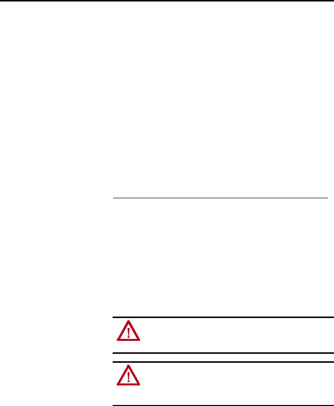
Installation
The 100-C09…C43 Starter Assembly installation instructions for use with Catalog Numbers 193-EC_ _B and -EC_ _D are shown in Figure 2.
18 |
Rockwell Automation Publication 193-UM002I-EN-P - December 2011 |
Installation & Wiring |
Chapter 2 |
|
|
Figure 2 - 100-C09…C43 Starter Assembly Installation
22.5 N m
2 lb in
3
1
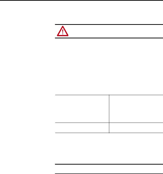
The 100-C60…C85 Starter Assembly installation instructions for use with
Catalog Numbers 193-EC_ _E are shown in Figure 3.
Figure 3 - 100-C60…C85 Starter Assembly Installation
1
2 4 N·m
35 lb-in
The 100-D95…D860 Starter Assembly installation instructions for use with
Catalog Numbers 193-EC_ _F, 193-EC_ _G, and -EC_ _H are shown below.
ATTENTION: The voltage ratings of the E3 Overload Relay’s output and trip relays must not be exceeded. If the voltage ratings are exceeded, an interposing relay must be used.
ATTENTION: Connect the internal metal shield to a solid earth ground via a low impedance connection.
Rockwell Automation Publication 193-UM002I-EN-P - December 2011 |
19 |

Chapter 2 Installation & Wiring
IMPORTANT Ground fault protection requires connection of an external core balance current transformer (CBCT).
IMPORTANT For identification of the proper CT ratio to be programmed, refer to the product nameplate.
Figure 4 - 100-D95…D860 Starter Assembly Installation |
|||||
1 |
|
|
|
|
4 |
|
|
|
Supplied |
|
|
|
|
|
with Contactor |
|
|
|
1 |
|
|
|
|
|
|
|
|
Supplied |
|
100-D95 / D110 |
|
11 N·m (100 lb-in) |
with |
|
|
|
Contactor |
|
|||
100-D95E / D110E / D115E |
|
|
|
||
22 N·m (195 lb-in) |
|
Accessory 193-EIMD shown. |
|||
100-D115 / D140 / D180 |
|
|
|||
|
43 N·m (380 lb-in) |
|
|||
100-D210 / D420 |
|
|
|
||
100-D630 / D860 |
|
68 N·m (600 lb-in) |
|
|
|
2 |
|
|
|
|
5 |
|
193-EC _ _ F |
(M5) 3.4 N·m (30 lb-in) |
|
||
|
193-EC _ _ G |
(M6) 7.3 N·m (65 lb-in) |
|
||
|
193-EC _ _ H |
(M12 Provided) |
|
|
|
|
45 N·m (400 lb-in) |
|
|
||
|
|
|
|
|
|
3 |
6 |
b
a
a
20 |
Rockwell Automation Publication 193-UM002I-EN-P - December 2011 |
Installation & Wiring |
Chapter 2 |
|
|
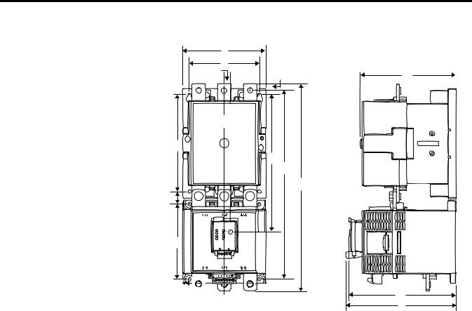
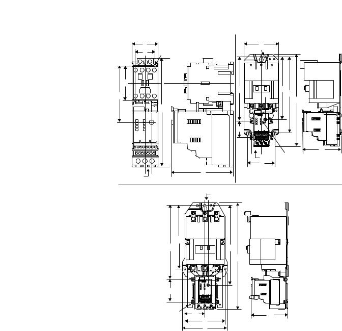
Approximate Dimensions
Approximate dimensions are shown in millimeters (inches). Dimensions are not intended to be used for manufacturing purposes.
Figure 5 - Overload Relay 193-EC_ _ B, D, & E with Contactor 100-C*
A |
|
|
D2 |
ØD |
H |
|
||
D1 |
|
|
|
E1 |
|
|
|
B |
|
|
B1 |
11.4 |
|
C |
(29/64) |
|
|
F1 |
|
|
|
|
|
|
Height B |
|
|
|
|
|
|
|
|
|
Cat. No. |
|
193-EIMD |
|
|
|
|
|
|
|
|
|||
Overload |
|
Contactor |
Width |
|
|
|
Depth |
|
|
|
|
|
|
|
|
|
|
|
|
|
|
|
|
||||
Relay |
|
100- |
A |
without |
with |
B1 |
C |
E1 |
F1 |
D1 |
D2 |
H |
Ø D |
|
|
|
|
|
|
|
|
|
|
|
|
|
|
193-EC_ _B |
|
C09, C-12, |
45 |
188.3 |
207.7 |
145.1 |
107 |
67.9 |
53.2 |
60 |
35 |
85.1 |
4.2 |
|
|
C16, C23 |
(1-25/32) |
(7-13/32) |
(8-11/64) |
(5-23/32) |
(4-7/32) |
(2-43/64) |
2-3/32) |
(2-23/64) |
(1-3/8) |
(3-23/64) |
(11/64) |
|
|
|
|
|
|
|
|
|
|
|
|
|
|
193-EC_ _D |
|
C30, C37 |
|
|
|
|
|
|
|
|
|
104 |
|
|
|
|
|
|
|
|
|
|
|
|
|
(4-3/32) |
|
|
|
|
|
|
|
|
|
|
|
|
|
|
|
|
|
C43 |
54 |
|
|
|
|
|
62.2 |
|
45 |
107 |
|
|
|
|
(2-1/8) |
|
|
|
|
|
(2-7/16) |
|
(1-25/32) |
(4-7/32) |
|
|
|
|
|
|
|
|
|
|
|
|
|
|
|
193-EC_ _E |
|
C60, C72, |
72 |
236.1 |
255.5 |
173.2 |
124.6 |
89.8 |
80.2 |
100 |
55 |
125.5 |
5.5 |
|
|
C85 |
(2-53/64) |
(9-19/64) |
(10-1/16) |
(6-13/16) |
(4-29/32) |
(3-17/32) |
(3-9/64) |
(3-15/16) |
(2-11/64) |
(4-15/16) |
(7/32) |
|
|
|
|
|
|
|
|
|
|
|
|
|
|
Rockwell Automation Publication 193-UM002I-EN-P - December 2011 |
21 |
Chapter 2 Installation & Wiring
Figure 6 - Overload Relay 193-E_ _F, G, & H with Contactor 100-D*
A |
|
|
11.4 G |
F |
D |
(0.45) |
C
L
H 

E1
B1
B
K
J
ØM

C L
|
|
|
|
Height B |
|
|
|
|
|
|
|
|
|
|
|
|
Cat. No. |
|
193-EIMD |
|
|
|
|
|
|
|
|
|
|
|
|||
Overload |
|
Contactor |
Width |
|
|
|
Depth |
|
|
|
|
|
|
|
|
|
|
|
|
|
|
|
|
|
|
|
|
|
|
||||
Relay |
|
100- |
A |
without |
with |
B1 |
C |
D |
E1 |
F |
G |
H |
J |
K |
L |
ØM |
|
|
|
|
|
|
|
|
|
|
|
|
|
|
|
|
|
193-EC_ _F |
|
D95, D110 |
120 |
336.3 |
418 |
311.8 |
175.1 |
156 |
216.1 |
12.5 |
100 |
145 |
135 |
22.3 |
180.9 |
5.6 |
|
|
|
(4.72) |
(13.24) |
(16.46) |
(12.27) |
(6.89) |
(6.14) |
(8.51) |
(0.49) |
(3.94) |
(5.71) |
(5.31) |
(0.88) |
(7.12) |
(0.22) |
|
|
|
|
|
|
|
|
|
|
|
|
|
|
|
|
|
|
|
D140, D180 |
|
339.8 |
|
317.8 |
|
|
|
16 |
|
|
|
|
|
|
|
|
|
|
(13.38) |
|
(12.51) |
|
|
|
(0.63) |
|
|
|
|
|
|
|
|
|
|
|
|
|
|
|
|
|
|
|
|
|
|
|
193-EC_ _G |
|
D210, D250, |
155 |
385.8 |
487.4 |
360.8 |
198.9 |
180 |
255 |
21 |
130 |
180 |
140 |
23.5 |
204.7 |
|
|
|
D300, D420 |
(6.10) |
(15.19) |
(19.19) |
(14.2) |
(7.83) |
(7.09) |
(10.04) |
(0.83) |
(5.12) |
(7.09) |
(5.51) |
(0.93) |
(8.06) |
|
|
|
|
|
|
|
|
|
|
|
|
|
|
|
|
|
|
193-EC_ _H |
|
D630, D860 |
255 |
552 |
915 |
508 |
291.7 |
270.7 |
373.9 |
52.5 |
226 |
230 |
108 |
109 |
297.5 |
13 |
|
|
|
(10.04) |
(21.73) |
(36.02) |
(20.0) |
(11.49) |
(10.66) |
(14.72) |
(2.07) |
(8.90) |
(8.90) |
(4.25) |
(4.29) |
(11.71) |
(0.51) |
|
|
|
|
|
|
|
|
|
|
|
|
|
|
|
|
|
22 |
Rockwell Automation Publication 193-UM002I-EN-P - December 2011 |
Installation & Wiring |
Chapter 2 |
|
|
Figure 7 - Overload Relay 592-EC_ _ T, C, & D with NEMA Contactor
Size 00 |
|
Size 0...2 |
|
|
A |
|
A |
|
|
D |
ØF |
ØF |
|
|
|
|
|
||
E |
|
J |
H |
|
H |
|
E |
||
|
|
|
B |
|
|
|
|
|
|
|
B |
|
|
|
|
|
K |
|
|
|
|
|
|
C |
|
|
L |
|
11.4 |
|
|
|
(29/64) |
|
|
|
D |
|
|
|
|
|
|
|
11.4 |
|
C |
|
|
(29/64) |
|
|
|
|
|
Size 3 |
11.4 |
|
|
|
|
(29/64) |
|
|
|
E |
|
|
|
|
J |
H |
|
|
|
|
B |
|
|
|
K |
|
|
|
|
ØF |
L |
C |
|
|
|
D |
|
|
|
|
A |
|
|
|
|
|
Height B |
|
|
|
|
|
|
|
|
|
|
|
|
193-EIMD |
|
|
|
|
|
|
|
|
|
Cat. No. |
NEMA |
|
|
|
|
|
|
|
|
|
|
|
|
|
|
|
|
|
|
|
|
|
|
||
Overload |
Contactor |
Width |
|
|
Depth |
|
|
|
|
|
|
|
Relay |
Size |
A |
without |
with |
C |
D |
E |
ØF |
H |
J |
K |
L |
|
|
|
|
|
|
|
|
|
|
|
|
|
592-EC_ _T |
00 |
45 |
188.3 |
207.7 |
107 |
35 |
60 |
4.2 |
97.9 |
— |
— |
— |
|
|
(1-25/32) |
(7-13/32) |
(8-11/64) |
(4-7/32) |
(1-3/8) |
(2-23/64) |
(11/64) |
(3-27/32) |
|
|
|
|
|
|
|
|
|
|
|
|
|
|
|
|
592-EC_ _C |
0, 1 |
90.4 |
|
|
112.1 |
69.9 |
179.4 |
5.15 |
159.4 |
163 |
47.5 |
27.5 |
|
|
(3-9/16) |
|
|
(4-13/32) |
(2-3/4) |
(7-1/16) |
((13.64) |
(7-15/32) |
(6-7/16) |
(1-7/8) |
(1-5/64) |
|
|
|
|
|
|
|
|
|
|
|
|
|
|
2 |
100 |
|
|
|
80 |
219.3 |
5.54 |
186 |
189.5 |
|
|
|
|
(3-15/16) |
|
|
|
(3-5/32) |
(8-5/8) |
(7/32) |
(7-21/64) |
(7-15/32) |
|
|
|
|
|
|
|
|
|
|
|
|
|
|
|
592-EC_ _D |
3 |
155.5 |
236.1 |
255 |
126.3 |
139.9 |
219.9 |
7.1 |
276.7 |
256.3 |
78.5 |
42.3 |
|
|
(6-1/8) |
(9-19/64) |
(10-1/16) |
(4-31/32) |
(5-33/64) |
(8-43/64) |
(9/32) |
(10.9) |
(10-3/32) |
(3-3/32) |
(1-21/32) |
|
|
|
|
|
|
|
|
|
|
|
|
|
Rockwell Automation Publication 193-UM002I-EN-P - December 2011 |
23 |
Chapter 2 Installation & Wiring
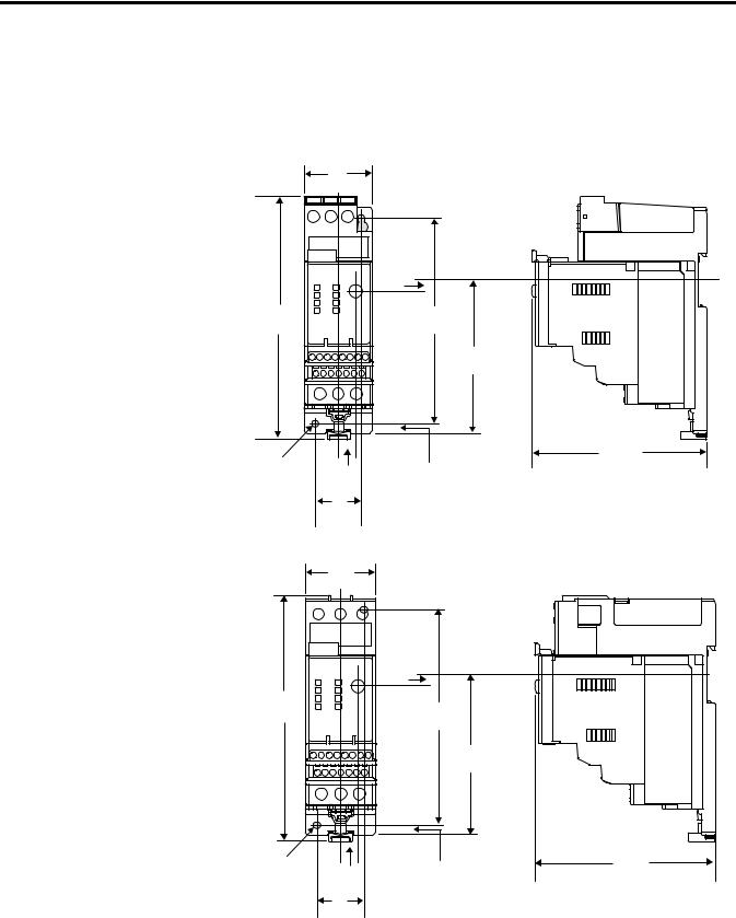
Separate Panel Adapter Approximate Dimensions
Approximate dimensions are shown in millimeters (inches). Dimensions are not intended to be used for manufacturing purposes.
Figure 8 - 193-ECPM1 Panel Adapter for use with Cat. No. 193-EC_ _B
|
45 |
|
|
|
(1-25/32) |
|
|
|
|
7.3 |
|
|
|
(9/32) |
|
159.3 |
|
135 |
|
(6-17/64) |
|
(5-5/16) |
|
|
|
100.5 |
|
|
|
(3-31/32) |
|
|
|
115 |
|
Ø 4.4 |
|
(4-17/32) |
|
(11/64) |
11.4 |
6.1 |
|
(1/4) |
|||
|
(29/64) |
||
|
|
||
|
30 |
|
|
|
(1-3/16) |
|
Figure 9 - 193-ECPM2 Panel Adapter for use with Cat. No. 193-EC_ _D & Z
|
45 |
|
|
|
(1-25/32) |
|
|
|
7.3 |
|
|
|
(9-32) |
|
|
154.2 |
|
135 |
|
(6-5/64) |
|
|
|
|
(5-5/16) |
|
|
|
|
|
|
|
|
100.5 |
|
|
|
(3-31/32) |
|
Ø 4.4 |
11.4 |
6.1 |
115 |
(11/64) |
(4-17/32) |
||
|
(29/64) |
(1/4) |
|
|
30 |
|
|
|
(1-3/16) |
|
|
24 |
Rockwell Automation Publication 193-UM002I-EN-P - December 2011 |
Installation & Wiring |
Chapter 2 |
|
|
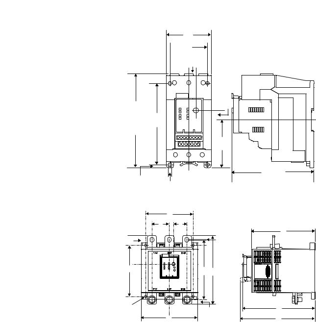
Figure 10 - 193-ECPM3 Panel Adapter for use with Cat. No. 193-EC_ _E
71.7 (2-53/64)
 60 (2-23/64)
11.4
(29/64)
150.5 |
15 |
|
(19/32) |
||
(5-15/16) |
|
|
155.1 |
130 |
|
(5-1/8) |
||
(6-7/64) w/ |
||
193-EIMD |
|
|
|
77 |
|
|
(3-1/32) |
|
|
131.2 |
|
5.0 |
(5-11/64) |
|
(13/64) |
Ø 5.5 |
|
|
(7/32) |
Figure 11 - Separate Panel Adapter for use with Cat. No. 193-EC_ _ F, G, & H
|
D |
|
E |
F |
E |
|
M |
|
|
|
|
G |
|
K |
|
I |
|
H |
C |
B |
J |
L |
N |
|
||
|
A |
P |
|
Overload |
|
|
|
|
|
|
|
|
|
|
|
|
|
|
|
NoCat. . A |
B |
C |
D |
E |
F |
G |
H |
I |
J |
K |
L |
M |
N |
P |
|
|
|
|
|
|
|
|
|
|
|
|
|
|
|
|
|
|
|
|
193-EC_ _ F |
4.72 |
7.19 |
6.09 |
3.94 |
1.54 |
0.45 |
1.03 |
5.32 |
1.94 |
0.22 |
0.24 |
0.47 |
5.95 |
6.89 |
7.12 |
|
|
(120.0) |
(182.6) |
(154.6) |
(100) |
(39) |
(11.4) |
(26.3) |
(135) |
(49.4) |
(5.6) |
(6.0) |
(12) |
(151.2) |
(175) |
(180.9) |
|
|
|
|
|
|
|
|
|
|
|
|
|
|
|
|
|
|
193-EC_ _ G |
6.09 |
7.40 |
6.41 |
5.12 |
1.89 |
0.45 |
1.06 |
5.51 |
2.03 |
0.26 |
0.08 |
0.49 |
6.89 |
7.83 |
8.06 |
|
|
(154.7) |
(188.1) |
(162.8) |
(130) |
(48) |
(11.4) |
(26.8) |
(140.0) |
(51.5) |
(6.5) |
(2.0) |
(12.5) |
(175) |
(198.9) |
(204.7) |
|
|
|
|
|
|
|
|
|
|
|
|
|
|
|
|
|
|
193-EC_ _H |
10.0 |
10.28 |
8.54 |
8.90 |
2.76 |
0.45 |
3.97 |
4.24 |
1.37 |
0.53 |
— |
0.87 |
10.54 |
11.49 |
11.72 |
|
|
(255.0) |
(261.0) |
(217.0) |
(226) |
(70) |
(11.4) |
(100.8) |
(107.7) |
(134.9) |
(13.5) |
|
(22.0) |
(267.8) |
(291.7) |
(297.5) |
|
|
|
|
|
|
|
|
|
|
|
|
|
|
|
|
|
Rockwell Automation Publication 193-UM002I-EN-P - December 2011 |
25 |
Chapter 2 Installation & Wiring
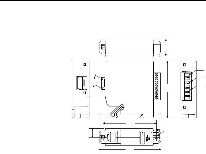
Voltage Input Module
The voltage input module, Cat. No. 193-NVEC5VIM, is an add-on accessory for use with the E3 Plus. Approximate dimensions are shown in millimeters (inches). Dimensions are not intended to be used for manufacturing purposes.
Figure 12 - 193-NVEC5VIM Voltage Input Module
 0.886 (22.5)
|
L1 |
|
L2 |
2.972 |
L3 |
|
|
(75.5) |
|
|
2.782 |
|
|
(70.65) |
|
0.457 |
Ø 0.177 |
|
(4.5) |
||
(11.6) |
||
|
||
|
3.216 |
|
|
(82.0) |
Specifications |
Power Terminals |
|
|
|
|
|
Table 2 - Wire Size & Torque Specification |
|
|
|
|
|
|
|
|
|
|
|
|
|
Cat. No. |
||
|
|
|
193-EC_ _B & D, |
|
193-EC_ _E, |
|
|
|
|
||
|
Wire Type |
Conductor Torque |
592-EC_ _T, C |
|
592-EC_ _D |
|
|
|
|
|
|
|
Stranded/Solid [AWG] |
Single |
#14…6 AWG |
|
#12…1 AWG |
|
|
|
22 lb-in. |
|
35 lb-in. |
|
|
|
|
|
|
|
|
Multiple |
#10…6 AWG |
|
#6…2 AWG |
|
|
|
30 lb-in. |
|
35 lb-in. |
|
|
|
|
|
|
|
Flexible-Stranded with Ferrule Metric |
Single |
2.5…16 mm2 |
|
4…35 mm2 |
|
|
|
2.5 Nm |
|
4 Nm |
|
|
|
|
|
|
|
|
Multiple |
6…10 mm2 |
|
4…25 mm2 |
|
|
|
3.4 Nm |
|
4 Nm |
|
|
|
|
|
|
|
Coarse-Stranded/Solid Metric |
Single |
2.5…25 mm2 |
|
4…50 mm2 |
|
|
|
2.5 Nm |
|
4 Nm |
|
|
|
|
|
|
|
|
Multiple |
6…16 mm2 |
|
4…35 mm2 |
|
|
|
3.4 Nm |
|
4 Nm |
|
|
|
|
|
|
26 |
Rockwell Automation Publication 193-UM002I-EN-P - December 2011 |

Installation & Wiring |
Chapter 2 |
|
|
Three-Pole Terminal Blocks
Table 3 - Three-Pole Terminal Blocks
Cat. No. 100-DTB1890 (A) 6…1/0 AWG, 16…50 mm2
(B) 6 AWG…250 MCM, 16…120 mm2 90…110 lb.-in., 10…12 Nm
100-DTB420 (2) 4 AWG…600 MCM, 25…240 mm2 180…220 lb.-in., 20…25 Nm
Terminal Lug Kits
Table 4 - Terminal Lug Kits
Cat. No. 100-DL |
110 |
Lug |
6…2/0 AWG, 16…70 mm2 |
|
|
|
90…110 lb.-in., 10…12 Nm |
|
|
|
|
|
|
Terminal |
13/32 in, 10 mm |
|
|
|
150 lb.-in., 17 Nm |
|
|
|
|
|
180 |
Lug |
6 AWG…250 MCM, 16…120 mm2 |
|
|
|
90…110 lb.-in., 10…12 Nm |
|
|
|
|
|
|
Terminal |
1/2 in., 13 mm |
|
|
|
275 lb.-in., 16 Nm |
|
|
|
|
|
420 |
Lug |
2 AWG…350 MCM |
|
|
|
375 lb.-in., 42 Nm |
|
|
|
|
|
|
Terminal |
11/16 in., 17 mm |
|
|
|
140 lb.-in., 16 Nm |
|
|
|
|
|
630 |
Lug |
2/0 AWG…500 MCM, 70…240 mm2 |
|
|
|
400 lb.-in., 45 N |
|
|
|
|
|
|
Terminal |
3/4 in, 19 mm |
|
|
|
600 lb.-in., 68 Nm |
|
|
|
|
|
860 |
Lug |
2/0 AWG…500 MCM, 70…240 mm2 |
|
|
|
400 lb.-in., 45 Nm |
|
|
|
|
|
|
Terminal |
3/4 in, 19 mm |
|
|
|
600 lb.-in., 68 Nm |
|
|
|
|
Control, DeviceNet, & Voltage Input Module Terminals
Table 5 - Wire Size & Torque Specification
Wire Type |
Conductor Torque |
All Cat. No. Types |
|
|
|
Stranded/Solid [AWG] |
Single |
24...12 AWG |
|
|
|
|
Multiple |
24...16 AWG |
|
(stranded only) |
5 lb-in |
|
|
|
Rockwell Automation Publication 193-UM002I-EN-P - December 2011 |
27 |

Chapter 2 Installation & Wiring
Wire Type |
Conductor Torque |
All Cat. No. Types |
|
|
|
Flexible-Stranded with Ferrule Metric |
Single |
0.25…2.5 mm2 |
|
Multiple |
0.5...0.75 mm2 |
|
|
0.55 Nm |
|
|
|
Coarse-Stranded/Solid Metric |
Single |
0.2...2.5 mm2 |
|
Multiple |
0.2...1.5 mm2 |
|
|
0.55 Nm |
|
|
|
Table 6 - Maximum Wire Length (PTC & input)
Minimum Cross Section |
mm2 |
0.5 |
0.75 |
1.5 |
2.5 |
4.0 |
|
AWG |
20 |
18 |
16 |
14 |
12 |
|
|
|
|
|
|
|
Maximum Length |
meters |
160 |
250 |
400 |
600 |
1000 |
|
|
|
|
|
|
|
|
feet |
525 |
825 |
1300 |
1950 |
3200 |
|
|
|
|
|
|
|
The use of shielded cable is recommended for the PTC thermistor circuit to assist in obtaining compliance with Electromagnetic Compatibility (EMC) requirements. Shielded cable is recommended for the input circuits, where wire lengths exceed 200 meters (656 feet).
NOTE: For reliable input signal processing, input wiring should be routed in raceways separate from power cabling.
Table 7 - Ground Fault Sensor Terminals (S1 & S2)
Wire Type |
Shielded, Twisted Pair |
|
|
Cross Section |
0.2…4.0 mm2 (#24…12 AWG) |
Torque |
0.55 N·m (5 lb.-in.) |
28 |
Rockwell Automation Publication 193-UM002I-EN-P - December 2011 |

|
|
|
|
|
|
Installation & Wiring Chapter 2 |
||
|
|
|
|
|
|
|
|
|
Terminal Designations |
Control Terminals |
|
|
|
||||
|
Table 8 - Control Terminal Designation |
|||||||
|
|
|
|
|
|
|
|
|
|
Terminal |
Reference Description |
||||||
|
|
|
|
|
|
|
|
|
|
1 |
IN1 |
|
1 |
|
|||
|
|
|
|
|
|
|
|
|
|
2 |
IN2 |
General Purpose Sinking Input Number: |
2 |
|
|||
|
|
|
|
|
|
|
|
|
|
3 |
IN3 |
3 |
|||||
|
|
|||||||
|
|
|
|
|
|
|
|
|
|
4 |
IN4 |
|
4 |
||||
|
|
|
|
|
|
|
|
|
|
5 |
V+ |
+24V |
|||||
|
|
|
|
|
|
|
|
|
|
6 |
V+ |
|
|
|
|||
|
|
|
|
|
|
|
|
|
|
7 |
IN5 |
General Purpose Sinking Input Number: |
5 |
||||
|
|
|
|
|
|
|
|
|
|
8 |
IN6 |
6 |
|||||
|
|
|||||||
|
|
|
|
|
|
|
|
|
|
|
|
|
|
END |
Earth Ground |
||
|
|
|
|
|
||||
|
|
|
|
|
|
|
|
|
|
13/14 |
OUT A |
Output A |
|||||
|
|
|
|
|
|
|
|
|
|
23/24 |
OUT B |
Output B |
|||||
|
|
|
|
|
|
|
|
|
|
95/96 |
Trip Relay |
Trip Relay |
|||||
|
|
|
|
|
|
|
|
|
|
IT1/IT2 |
PTC |
Thermistor (PTC) Input |
|||||
|
|
|
|
|
|
|
|
|
|
S1/S2 |
— |
External Ground Fault Sensor Input |
|||||
|
|
|
|
|
|
|
|
|
Features are available only with the E3 Plus Overload Relay (Cat. No. 193/592-EC2 and 193/592-EC3).
Available only on Cat. Nos. 193/592-EC5_ _.
An earth ground connection to this terminal will assist in obtaining compliance with EMC requirements.
The use of shielded cable is recommended for the positive PTC thermistor circuit to assist in obtaining compliance with EMC requirements.
Available only on Cat. No. 193/592-EC3_ _ and 193/592-EC4_ _.
DeviceNet Terminals
Grounding
Table 9 - DeviceNet Terminal Designation
Terminal |
Signal |
Function |
Color |
|
|
|
|
1 |
V- |
Common |
Black |
|
|
|
|
2 |
CAN_L |
Signal Low |
Blue |
|
|
|
|
3 |
Drain |
Shield |
Non-Insulated |
|
|
|
|
4 |
CAN_H |
Signal High |
White |
|
|
|
|
5 |
V+ |
Po9wer Supply |
Red |
|
|
|
|
The following grounding recommendations are provided to ensure EMC requirements during installation.
Rockwell Automation Publication 193-UM002I-EN-P - December 2011 |
29 |

Chapter 2 Installation & Wiring
Short-Circuit Ratings
•The earth ground terminal of the E3 Overload Relay shall be connected to a solid earth ground via a low-impedance connection.
•Installations employing an external ground fault sensor shall ground the cable shield at the sensor with no connection made at the E3 Plus Overload Relay.
•The PTC thermistor cable shield shall be grounded at the E3 Plus Overload Relay with no connection made at the opposite end.
The E3 Overload Relay is suitable for use on circuits capable of delivering not more than the RMS symmetrical amperes listed in the following tables.
Short-Circuit Ratings
Table 10 - UL
|
Cat. No. |
|
|
Maximum |
|
|
||
|
|
|
|
|
|
|
|
|
|
193-EC_ _ |
592-EC_ _ |
|
Available Fault Current [A] |
Voltage [V] |
|
|
|
|
|
|
|
|
|
|
|
|
|
B |
T |
5,000 |
|
600 |
|
|
|
|
|
|
|
|
|
|
|
|
|
D |
C |
|
|
|
|
|
|
|
|
|
|
|
|
|
|
|
|
E |
D |
10,000 |
|
|
|
|
|
|
|
|
|
|
|
|
|
|
|
F |
|
|
|
|
|
|
|
|
|
|
|
|
|
|
|
|
|
G |
|
18,000 |
|
|
|
|
|
|
|
|
|
|
|
|
|
|
|
H |
|
42,000 |
|
|
|
|
|
|
|
|
|
|
|
|
|
|
|
Z |
|
5,000 |
|
|
|
|
|
|
|
|
|
|
|
|
|
|
Table 11 - IEC |
|
|
|
|
|
|
||
|
|
|
|
|
|
|
|
|
|
Cat. No. |
|
Prospective |
Conditional Short-Circuit |
|
|
||
|
|
|
|
|
|
|||
|
193-EC_ _ |
592-EC_ _ |
|
Current Ir [A] |
Current Iq [A] |
|
Maximum Voltage [V] |
|
|
B |
T |
|
1,000 |
100,000 |
|
|
690 |
|
|
|
|
|
|
|
|
|
|
D |
C |
|
3,000 |
|
|
|
|
|
|
|
|
|
|
|
|
|
|
E |
D |
|
5,000 |
|
|
|
|
|
|
|
|
|
|
|
|
|
30 |
Rockwell Automation Publication 193-UM002I-EN-P - December 2011 |
Loading...