

Allegro A3196LU, A3196LLT Datasheet
Always order by complete part number, e.g., A3197LU .
3197
PROTECTED, HIGH-TEMPERATURE,
OPEN-COLLECTOR HALL-EFFECT LATCH
These open-collector Hall-effect latches are capable of sensing magnetic
fields while using an unprotected power supply. The A3197LLT and A3197LU
can provide position and speed information by providing a digital output for
magnetic fields that exceed their predefined switch points. These devices
operate down to zero speed and have switch points that are designed to be
extremely stable over a wide operating temperature and voltage range. The
latching characteristics make them ideal for use in pulse counting applications
when used with a multi-pole ring magnet. Thermal and output short-circuit
protection allow an increased wiring harness fault tolerance. The temperature
compensated switch points, the wide operating voltage range, and the integrated
protection make these devices ideal for use in automotive applications such as
transmission speed sensors and integrated wheel bearing speed sensors.
Each monolithic device contains an integrated Hall-effect transducer, a
temperature-compensated comparator, a voltage regulator, and a buffered 35 mA
output sink stage. Supply protection is made possible by the integration of
overvoltage and undervoltage shutdown circuitry that monitor supply fault
conditions and shut down the IC. Noise shutdown circuitry (patent applied for)
prevents the propagation of supply transients to the logic load. Output protection circuitry includes a current limit loop that limits the maximum output sink
current, and thermal protection circuitry that shuts down the device during an
over-heating condition such as with a shorted load.
The A3197LLT and A3197LU are rated for operation over an extended
temperature range of -40°C to +150°C. They are supplied in a three-lead SIP
(suffix ‘U’) or a surface-mount SOT-89 (suffix ‘LT’).
FEATURES
■ Internal Protection For Automotive (ISO/DIN) Transients
■ Operation From Unregulated Supply
■ Reverse Battery Protection
■ Undervoltage Lockout
■ Supply Noise-Suppression Circuitry
■ Output Short-Circuit Protection
■ Output Zener Clamp
■ Thermal Protection
■ Symmetrical Latching Switch Points
■ Operable with Multipole Ring Magnets
Data Sheet
27609.10A
ABSOLUTE MAXIMUM RATINGS
Supply Voltage, V
CC
(100 ms) ................................... 115 V*
(continuous) ............................... 28 V*
Reverse Battery Voltage, V
RCC
(100 ms) ................................... -100 V
(continuous) ............................... -35 V
Magnetic Flux Density, B .......... Unlimited
Output OFF Voltage, V
OUT
................. 26 V
Reverse Output Voltage V
OUT
......... -0.5 V
Continuous Output Current,
I
OUT
.......................................... 35 mA*
Reverse Output Current,
I
OUT
........................................ -100 mA
Package Power Dissipation,
PD....................................... See Graph
Junction Temperature, TJ................. 170°C
Operating Temperature Range,
T
A
..........................................
-40°C to +150°C
Storage Temperature, TS.................. 170°C
*Fault condition, internal overvoltage shutdown
above 28 V; output current limited above 35 mA.
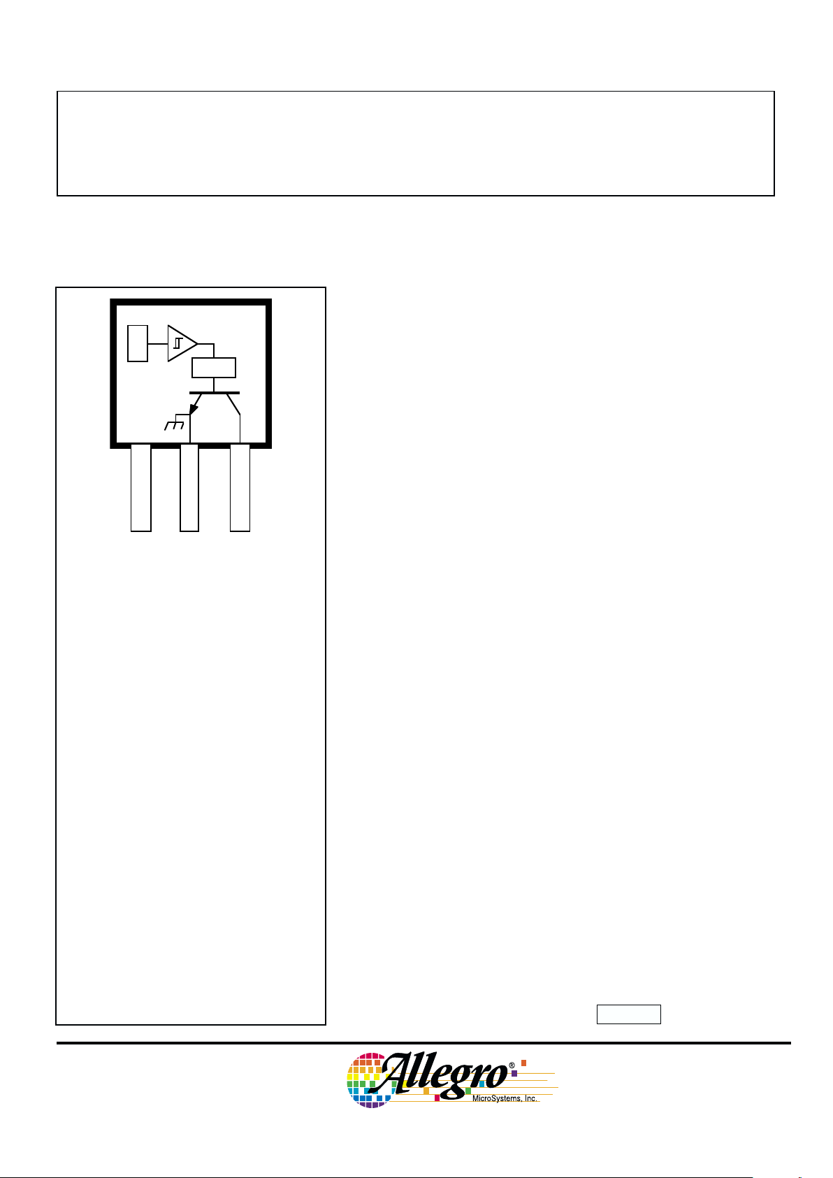
Dwg. PH-003-2
1
SUPPLY
V
CC
GROUND
32
OUTPUT
X
PTCT
3197
PROTECTED, HIGH-TEMP.,
OPEN-COLLECTOR
HALL-EFFECT LATCH
115 Northeast Cutoff, Box 15036
Worcester, Massachusetts 01615-0036 (508) 853-5000
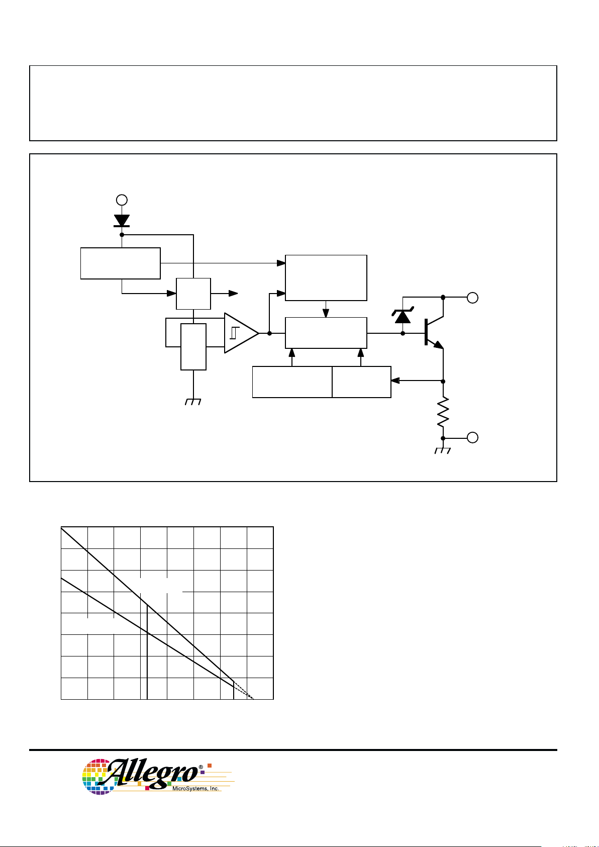
FUNCTIONAL BLOCK DIAGRAM
REG.
OUTPUT
3
X
Dwg. FH-012A
GROUND
V
CC
1
<1Ω
POWER UP &
TRANSIENT
PROTECTION
CURRENT
LIMIT
2
OVERVOLT.
LOCKOUT
THERMAL
SHUTDOWN
CONTROL
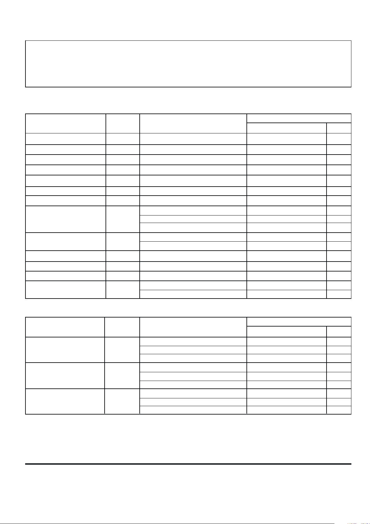
600
400
200
40 80 120
160
0
AMBIENT TEMPERATURE IN °C
ALLOWABLE PACKAGE POWER DISSIPATION IN mW
Dwg. GH-054A
"U" PACKAGE
R
θJA
= 183°C/W
"LT" PACKAGE
R
θJA
= 258°C/W
60 100 140 180
700
500
300
100
20
800
NOTE – Permitted duty cycle will be less than 100%
at maximum ambient temperature with high supply
voltages, i.e., TA ≥ 140°C, VCC ≥ 12 V, and the “LT”
package. The thermal shutdown circuitry does not
protect the device from these stresses (see Internal
Protective Features).
Copyright © 1995, 1999, Allegro MicroSystems, Inc.
3197
PROTECTED, HIGH-TEMP.,
OPEN-COLLECTOR
HALL-EFFECT LATCH
www.allegromicro.com
Limits
Characteristic Symbol Test Conditions Min. Typ. Max. Units
Operate Point B
OP
TA = -40°C 60 130 200 G
T
A
= +25°C 50 110 160 G
TA = +150°C 40 105 150 G
Release Point B
RP
TA = -40°C -200 -140 -60 G
TA = +25°C -160 -120 -50 G
TA = +150°C -150 -100 -40 G
Hysteresis B
hys
TA = -40°C 150 270 — G
(BOP - BRP)T
A
= +25°C 130 230 — G
T
A
= +150°C 110 205 — G
ELECTRICAL CHARACTERISTICS
over operating voltage and temperature range
(unless otherwise specified).
MAGNETIC CHARACTERISTICS over operating voltage range
(unless otherwise specified).
NOTES:BOP = magnetic operate point (output turns ON); BRP = magnetic release point (output turns OFF).
As used here, negative flux densities are defined as less than zero (algebraic convention).
Typical values are at TA = +25°C and VCC = 12 V (unless otherwise specified).
* Fault condition. Device is shut down and operation is not possible.
Limits
Characteristic Symbol Test Conditions Min. Typ. Max. Units
Supply Voltage V
CC
Operating (but VCC x ICC vs TA limited) V
CC(UV)
12 26 V
Overvoltage Shutdown* V
CC(OV)
B > B
OP
28 — 55 V
Undervoltage Shutdown* V
CC(UV)
B > B
OP
3.7 — 4.5 V
Output Voltage, On V
OUT(SAT)
B > B
OP, IOUT
= 30 mA, VCC = 16 V — 0.2 0.5 V
Output Leakage Current I
OFF
V
OUT
= 26 V — — 5.0 µA
Output Clamp Voltage V
OUT(CLMP)
B < BRP, VCC = 115 V*, I
OUT
= 0 28 32 40 V
Output Current Limit I
OUTMAX
B > BOP, V
OUT
= 12 V 355070mA
Supply Current I
CC
B < BRP, VCC = 24 V, I
OUT
= 0 — 5.2 9.0 mA
B > BOP, VCC = 24 V, I
OUT
= 20 mA — 7.8 12 mA
V
CC
= +115 V* — 8.0 17 mA
Reverse Battery Current* I
RCC
V
RCC
= -35 V* — -0.5 -5.0 mA
V
RCC
= -100 V* — -2.0 -10 mA
Output Rise Time t
r
CL = 20 pF, RL = 330 Ω, VBB = 12 V — 0.05 2.0 µs
Output Fall Time t
f
CL = 20 pF, RL = 330 Ω, VBB = 12 V — 0.30 5.0 µs
Thermal Shutdown Temp.* T
J
165 — 190 °C
Package Thermal Resist. R
θJA
“LT” Package — 258 — °C/W
“U” Package — 183 — °C/W
3197
PROTECTED, HIGH-TEMP.,
OPEN-COLLECTOR
HALL-EFFECT LATCH
115 Northeast Cutoff, Box 15036
Worcester, Massachusetts 01615-0036 (508) 853-5000
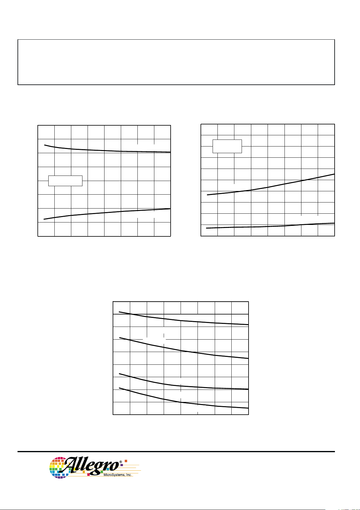
TYPICAL OPERATING CHARACTERISTICS
Output Saturation Voltage
Supply Current
0 25 50 75 100
AMBIENT TEMPERATURE IN °C
-50
Dwg. GH-052-2
125-25
SWITCH POINTS IN GAUSS
200
100
0
-100
-200
RELEASE POINT
OPERATE POINT
150
V = 5 V–24
V
CC
Switch Points
4.0
SUPPLY CURRENT IN mA
8.0
7.0
6.0
5.0
0 255075100
AMBIENT TEMPERATURE IN °C
-50
Dwg. GH-028-3
125-25 150
V = 5 V
CC
V = 5 V
CC
B ≥ B
OP
B ≤ B
RP
V = 24 V
CC
V = 24 V
CC
0 25 50 75
100
500
0
AMBIENT TEMPERATURE IN °C
400
200
-50
Dwg. GH-040-3
SATURATION VOLTAGE IN mV
150
-25
125
I = 30 m
A
OUT
300
100
CC
V = 12
V
I = 5 m
A
OUT
B ≥ B
OP
 Loading...