


Allegro A3144LLT, A3144EUA, A3144EU, A3144ELT, A3143LUA Datasheet
...
Data Sheet
27621.6A
Always order by complete part number, e.g., A3141ELT .
ABSOLUTE MAXIMUM RATINGS
at T
A
= +25°C
Supply Voltage, VCC............................ 28 V
Reverse Battery Voltage, V
RCC
........... -35 V
Magnetic Flux Density, B .......... Unlimited
Output OFF Voltage, V
OUT
.................. 28 V
Reverse Output Voltage, V
OUT
........... -0.5 V
Continuous Output Current, I
OUT
...... 25 mA
Operating Temperature Range, T
A
Suffix ‘E–’ .................. -40°C to +85°C
Suffix ‘L–’ ................ -40°C to +150°C
Storage Temperature Range,
TS.............................. -65°C to +170°C
These Hall-effect switches are monolithic integrated circuits with
tighter magnetic specifications, designed to operate continuously over
extended temperatures to +150°C, and are more stable with both
temperature and supply voltage changes. The unipolar switching
characteristic makes these devices ideal for use with a simple bar or rod
magnet. The four basic devices (3141, 3142, 3143, and 3144) are
identical except for magnetic switch points.
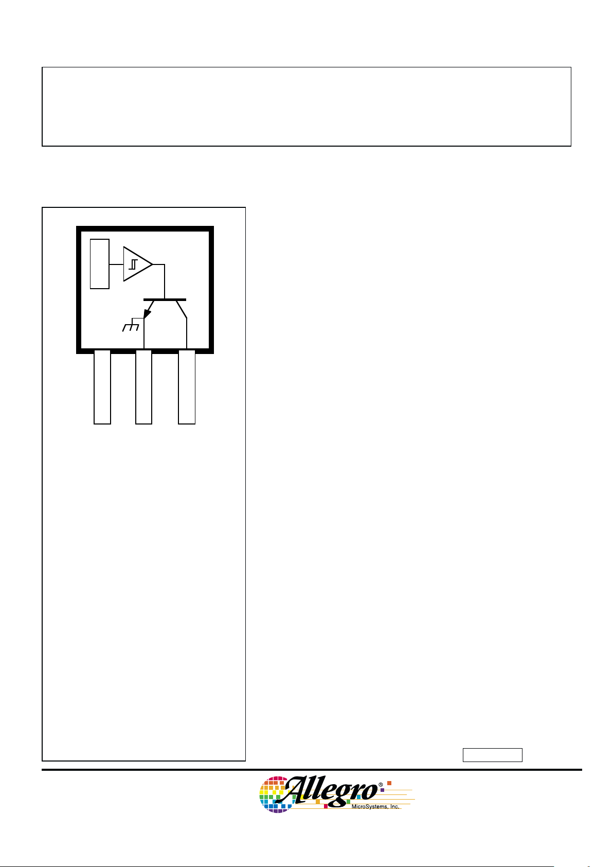
Each device includes a voltage regulator for operation with supply
voltages of 4.5 to 24 volts, reverse battery protection diode, quadratic
Hall-voltage generator, temperature compensation circuitry, smallsignal amplifier, Schmitt trigger, and an open-collector output to sink
up to 25 mA. With suitable output pull up, they can be used with
bipolar or CMOS logic circuits. The A3141– and A3142– are improved replacements for the UGN/UGS3140–; the A3144– is the
improved replacement for the UGN/UGS3120–.
The first character of the part number suffix determines the device
operating temperature range. Suffix ‘E–’ is for the automotive and
industrial temperature range of -40°C to +85°C. Suffix ‘L–’ is for the
automotive and military temperature range of -40°C to +150°C. Three
package styles provide a magnetically optimized package for most
applications. Suffix ‘–LT’ is a miniature SOT-89/TO-243AA transistor package for surface-mount applications; suffix ‘–U’ is a three-lead
plastic mini-SIP, while suffix ‘–UA’ is a three-lead ultra-mini-SIP.
FEATURES and BENEFITS
■ Superior Temp. Stability for Automotive or Industrial Applications
■ 4.5 V to 24 V Operation … Needs Only An Unregulated Supply
■ Open-Collector 25 mA Output … Compatible with Digital Logic
■ Reverse Battery Protection
■ Activate with Small, Commercially Available Permanent Magnets
■ Solid-State Reliability
■ Small Size
■ Resistant to Physical Stress
Pinning is shown viewed from branded side.
SENSITIVE HALL-EFFECT SWITCHES
FOR HIGH-TEMPERATURE OPERATION
3141
THRU
3144
Dwg. PH-003A
1
SUPPLY
V
CC
GROUND
32
OUTPUT
X

3141
THRU
3144
SENSITIVE
HALL-EFFECT SWITCHES
FOR HIGH-TEMP. OPERATION
115 Northeast Cutoff, Box 15036
Worcester, Massachusetts 01615-0036 (508) 853-5000
FUNCTIONAL BLOCK DIAGRAM
V
CC
X
REG.
Dwg. FH-005-2
GROUND
OUTPUT
3
2
1
MAGNETIC CHARACTERISTICS in gauss over operating supply voltage range.
NOTES: Typical values are at TA = +25°C and VCC = 8 V.
BOP = operate point (output turns ON); BRP = release point (output turns OFF); B
hys
= hysteresis (BOP - BRP).
*Complete part number includes a suffix to identify operating temperature range (E- or L-) and package type ( -LT, -U, or -UA).
ELECTRICAL CHARACTERISTICS at V
CC
= 8 V over operating temperature range.
Limits
Characteristic Symbol Test Conditions Min. Typ. Max. Units
Supply Voltage V
CC
Operating 4.5 — 24 V
Output Saturation Voltage V
OUT(SAT)
I
OUT
= 20 mA, B > B
OP
— 175 400 mV
Output Leakage Current I
OFF
V
OUT
= 24 V, B < B
RP
— <1.0 10 µA
Supply Current I
CC
B < BRP (Output OFF) — 4.4 9.0 mA
Output Rise Time t
r
RL = 820 Ω, CL = 20 pF — 0.04 2.0 µs
Output Fall Time t
f
RL = 820 Ω, CL = 20 pF — 0.18 2.0 µs
Part Numbers*
A3141– A3142– A3143– A3144–
Characteristic Min. Typ. Max. Min. Typ. Max. Min. Typ. Max. Min. Typ. Max.
B
OP
at TA = 25°C 50 100 160 130 180 230 220 280 340 70 — 350
over operating temp. range 30 100 175 115 180 245 205 280 355 35 — 450
B
RP
at TA = 25°C 10 45 130 75 125 175 165 225 285 50 — 330
over operating temp. range 10 45 145 60 125 190 150 225 300 25 — 430
B
hys
at TA = 25°C 20 55 80 30 55 80 30 55 80 20 55 —
over operating temp. range 20 55 80 30 55 80 30 55 80 20 55 —
Copyright © 1993, 1999, Allegro MicroSystems, Inc.
3141
THRU
3144
SENSITIVE
HALL-EFFECT SWITCHES
FOR HIGH-TEMP. OPERATION
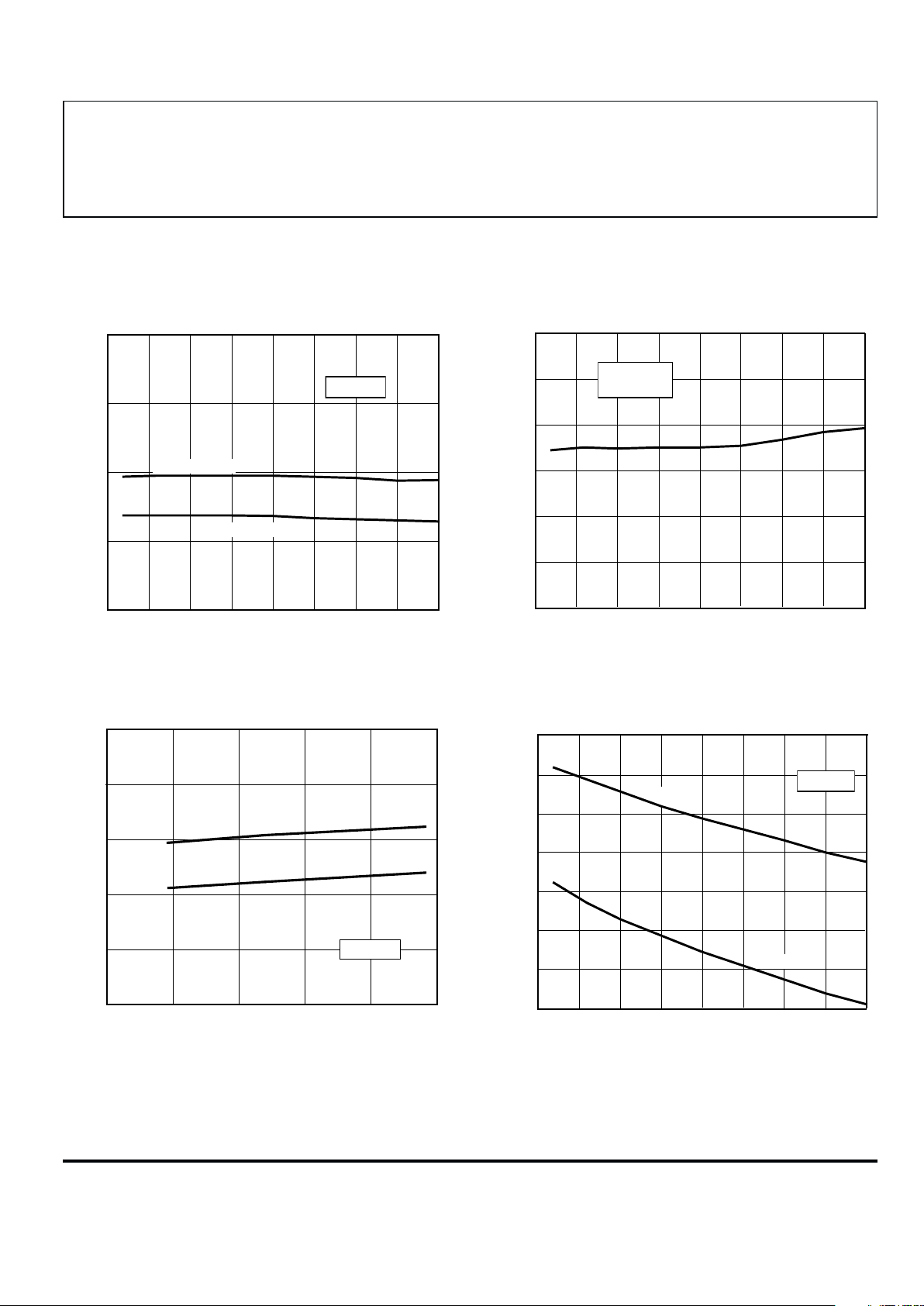
SUPPLY CURRENT
SUPPLY CURRENT
10 15 20 25
SUPPLY VOLTAGE IN VOLTS
0
Dwg. GH-041-1
5
SUPPLY CURRENT IN mA
0
2.0
4.0
6.0
8.0
10
B ≥ B
OP
B ≤ B
RP
T = +25°C
A
0 25 50 75
100
AMBIENT TEMPERATURE IN °C
-50
Dwg. GH-039-1
125
-25
V = 8
V
CC
SUPPLY CURRENT IN mA
7.0
6.0
5.0
4.0
150
B ≤ B
RP
B ≥ B
OP
TYPICAL OPERATING CHARACTERISTICS
A3142– SWITCH POINTS OUTPUT SATURATION VOLTAGE
0 25 50 75
100
300
0
AMBIENT TEMPERATURE IN °C
200
100
-50
Dwg. GH-040-1
SATURATION VOLTAGE IN mV
150
-25
125
I = 20 mA
V = 4.5–24 V
OUT
CC
0 50 100
AMBIENT TEMPERATURE IN °C
-50
Dwg. GH-044
SWITCH POINT IN GAUSS
300
400
200
100
OPERATE POINT
RELEASE POINT
V = 8 V
CC
150
0
-25 25 75 125
* Complete part number includes a suffix denoting operating temperature range (E- or L-) and package type ( -LT, -U, or -UA).