

Page 1
Page 2

Dear Client,
Thank you for choosing Alfa Romeo.
Alfa 147 GTA
Your
This booklet will help you to get to know the characteristics and operation of your vehicle.
The following pages contain all the indications necessary for you to be able to maintain the high standards of performance, quality, safety and
respect for the environment which characterise this
The Warranty Booklet also contains the regulations, the warranty certificate and a guide to the services offered by Alfa Romeo.
Services which are essential and precious because, when you purchase an Alfa Romeo you are not only acquiring a car, but the tranquillity that
comes from knowing that an efficient, willing and widespread organisation is at your service for any assistance problems you may have.
What’s more, every single component of the
dealer would be pleased to make arrangements for your car to be recycled.
Nature benefits in two ways: there’s no pollution from waste disposal and the demand for raw materials is reduced.
Have a good trip.
This booklet describes all the versions of the
cerning the trim level, engine and version purchased by you.
has been designed to guarantee the safety, comfort and driving pleasure typical of Alfa Romeo.
Alfa 147 GTA
Alfa 147 GTA
Alfa 147 GTA
.
is fully recyclable. At the end of your car’s useful lifespan, any Alfa Romeo
, so you should only consider the information con-
1
Page 3

VERY IMPORTANT!
FUEL CAPACITY
Ronly use unleaded petrol with no less than 95 R.O.N.
K
STARTING THE ENGINE
Engines with mechanical transmission: make sure the handbrake is pulled; put the gear lever into neutral; press the
clutch pedal down to the floor without touching the accelerator, then turn the ignition key to AVV and release it as soon as
the engine starts.
Engines with Selespeed transmission: keep the brake pedal fully depressed; turn the ignition key to AVV and re-
lease it as soon as the engine has started; the transmission sets to neutral automatically (the display shows position N).
PARKING ON FLAMMABLE MATERIAL
While working, the catalyst develops a very high temperature. Do not park the car over grass, dry leaves, pine needles or
any other inflammable materials: risk of fire.
RESPECTING THE ENVIRONMENT
The vehicle is fitted with a system that allows continuous diagnosis of the components correlated with emissions to ensure bet-
ter respect for the environment.
U
2
Page 4

ACCESSORY ELECTRICAL DEVICES
If after purchasing the car you wish to install accessories that need an electrical supply (with the risk of gradually draining
the battery), contact Alfa Romeo Authorised Services who will assess the overall electrical absorption and check whether the
쇵
CODE CARD
SCHEDULED SERVICING
THE OWNER HANDBOOK...
car system is able to withstand the load required.
Keep it in a safe place, not in the car. It is advisable to always keep the electronic code on the CODE card with you in case
emergency starting is necessary.
Correct maintenance makes it possible to preserve vehicle peformance levels and safety, respect for the environment and
low running costs unaltered over the course of time.
…you will find important information, advice and warnings for correct use, driving safety and vehicle maintenance over
time. Pay particular attention to the symbols
"
(personal safety)
#
(protecting the environment)
â
(vehicle safety).
3
Page 5

Any queries concerning servicing should be forwarded to the showroom from which the vehicle was purchased, the subsidiary company or to
our branch offices or any point of the Network.
Warranty Booklet
The Warranty Booklet is delivered together with every new vehicle and contains the regulations tied to the services given by Alfa Romeo and to
the warranty conditions.
Correctly carrying out the scheduled services specified by the manufacturer is the best way to maintain the performance, safety characteristics
and low running costs of your vehicle. It is also necessary to maintain warranty cover.
“Service” guide
This contains Alfa Romeo Authorised Services. The services can be recognised by the presence of the Alfa Romeo badge and logo.
The Alfa Romeo organisation in Italy can be found in the telephone directory under the letter “A” Alfa Romeo.
Not all of the models described in this booklet are available in all countries. Only some of the fittings described in this booklet are fitted as standard to the vehicle. The list of available accessories should be requested from the Alfa Romeo Dealers.
4
Page 6
THE SYMBOLS USED IN THIS BOOKLET
The symbols illustrated in these pages show the subjects
which should, in particular, be closely studied.
PERSONAL
SAFETY
Warning. Partially or
fully ignoring these rules may lead to
serious injury.
The texts, illustrations and specifications given in this booklet refer to the vehicle
As part of our ongoing striving to improve our products, Alfa Romeo may introduce technical changes during
production, therefore the specifications and fittings may be altered without prior notice.
For details on this subject, please apply to the manufacturer’s sales network.
PROTECTING THE
ENVIRONMENT
This indicates the correct procedures
to be followed to prevent the vehicle from
damaging the environment.
at the time of going to press.
VEHICLE
SAFETY
Warning. Partially or fully ignoring these
rules may lead to serious damage being
caused to the vehicle which, in some
circumstances, may cause forfeiture
of the warranty cover.
5
Page 7
GGEETTTTIINNGGTTOOKKNNOOW
WYYOOUURRCCAARR
SYMBOLS
On some of the components making up
your
Alfa 147 GTA
special coloured labels have been attached.
These labels bear symbols that remind you
of the precautions to be taken as regards that
particular component.
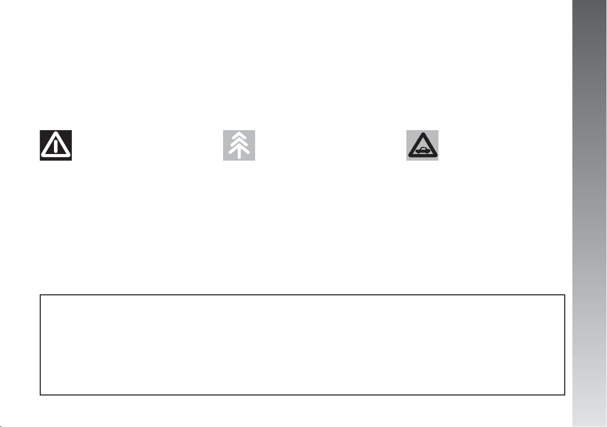
A summary list of the symbols (fig. 1) is
to be found under the bonnet.
GETTING TO KNOW YOUR CAR
, or near to them,
A0A0411m
THE ALFA ROMEO
CODE SYSTEM
To increase protection against attempted
theft, the car is fitted with an electronic engine lock system (Alfa Romeo CODE) which
is activated automatically when the key is
removed from the ignition. In fact the grip
of each key contains an electronic device
which modulates the radio frequency signal
transmitted when the engine is started by a
special aerial incorporated in the ignition
switch. This modulated signal is the “password” by which the control unit recognises
the key and only in this condition can the
engine be started.
KEYS
Two keys are delivered together with the
car, (A-fig. 2) with metal insert and remote control function.
The key remote control operates:
– Centralised door unlocking/locking
– Tailgate opening
– Electronic alarm on/off (if existing)
– Window and sunroof (if existing) un-
locking/locking.
A0A0002m
6
fig. 1
fig. 2
Page 8
The key metal insert operates:
– The ignition switch
-– the driver's door lock and, optional for
versions/markets where applicable, the passenger's door lock
– The passenger’s side air-bag deactiva-
tion
– The fuel tank plug lock.
IMPORTANT To guarantee the perfect
efficiency of the electronic devices contained
in keys, avoid letting tem directly exposed
to sunrays.
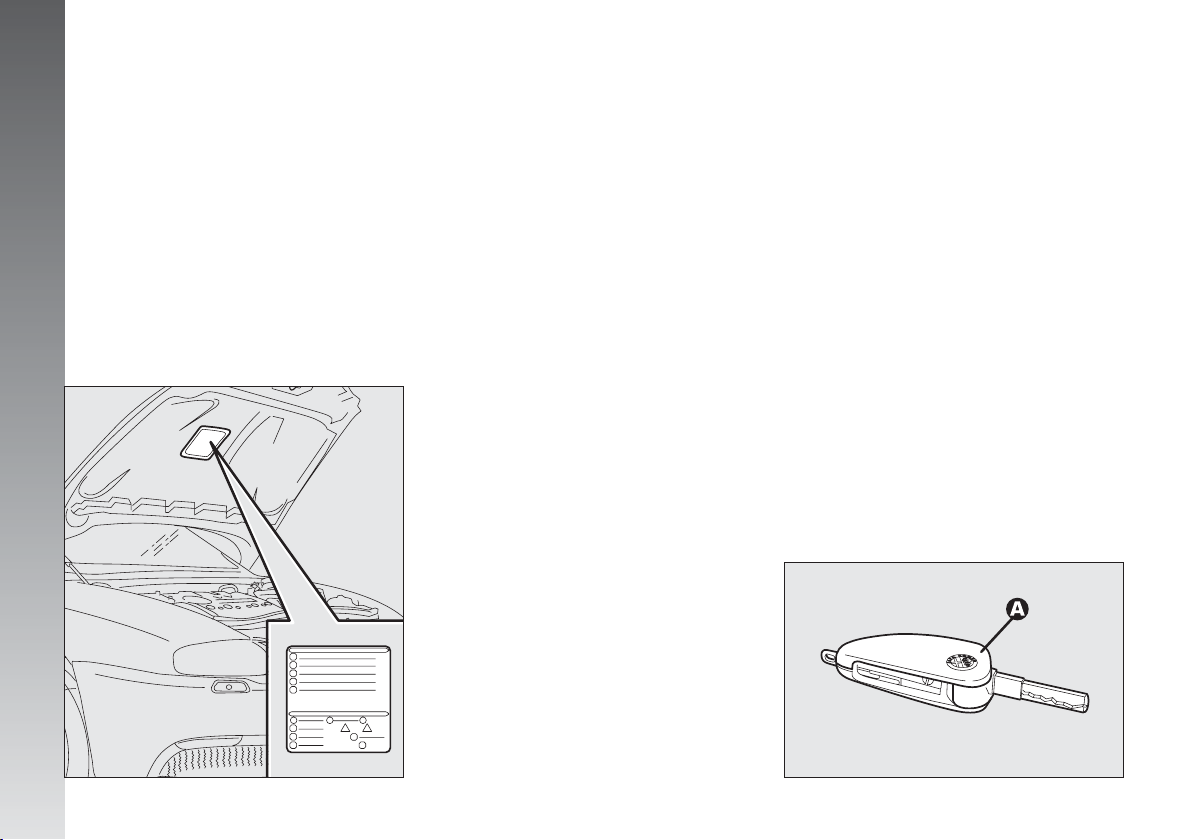
Together with the keys the CODE card is
provided (fig. 3), bearing in print the key
codes (both mechanical and electronic for
emergency start up).
The code numbers on the CODE card must
be kept in a safe place, not in the car.
The driver should always keep the electronic code given on the CODE card with
him/her in the event of having to carry out
emergency starting.
If the car changes owner,
the new owner must be
given all the keys and the
CODE card.
WARNING - U.K. VEHICLES ONLY
At the behest of the motor insurance companies the CODE card for emergency starting and remplacement of keys is not provided. If you need assistance please contact
your nearest Alfa Romeo Dealer or telephone
free phone 0800 717000.
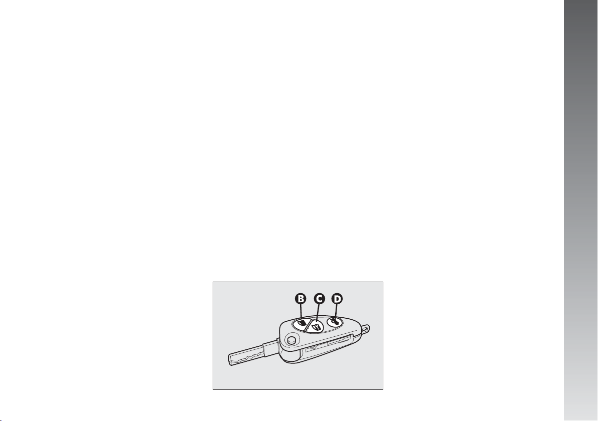
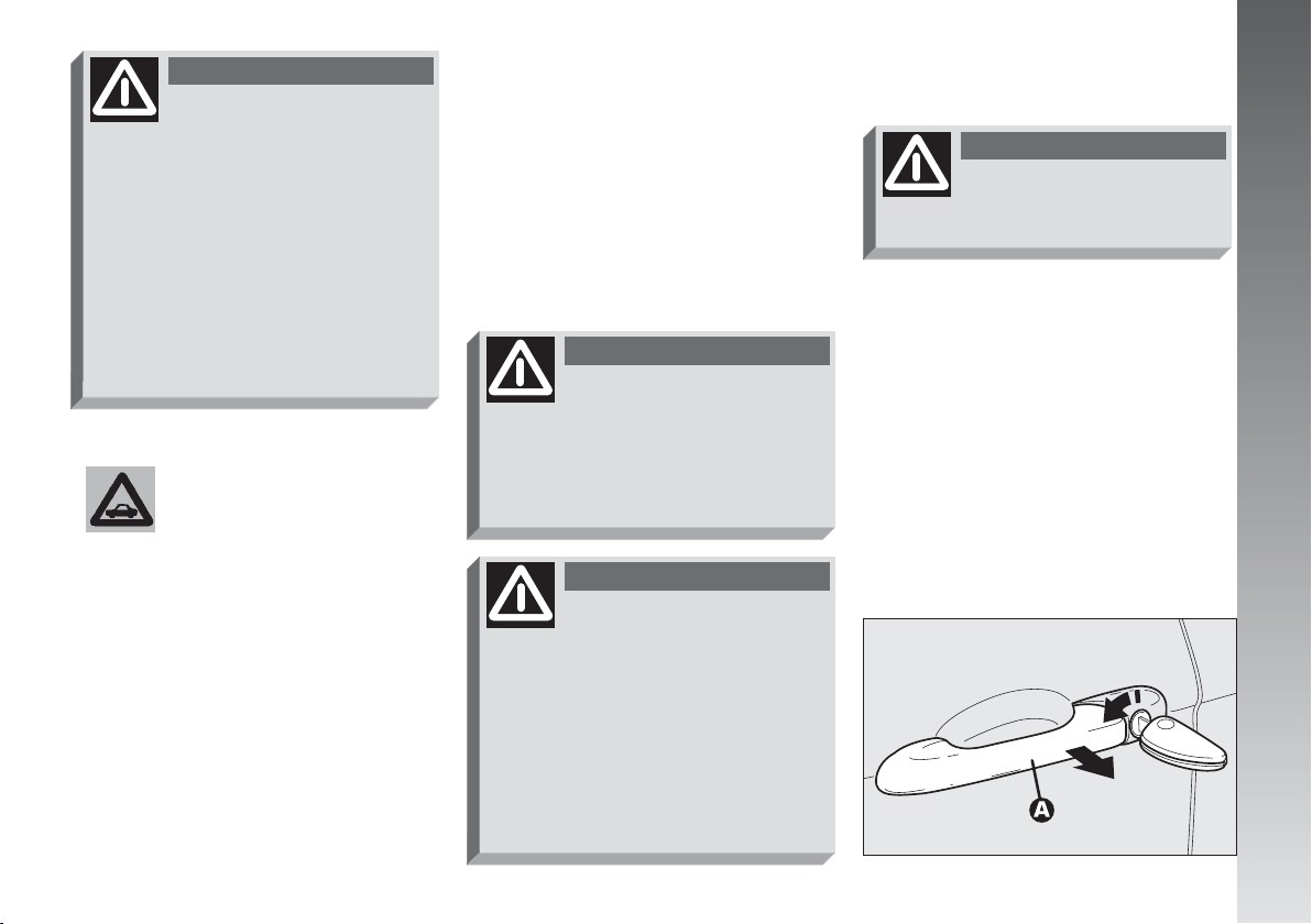
KEY WITH REMOTE CONTROL
For versions/markets where applicable,
the key with remote control (fig. 4) is fitted with:
– a metal insert (A) that can be enclosed
in the key grip
– a button (B) for remote door unlock-
ing and at the same time switching off the
electronic alarm
– a button (C) for remote door locking
and at the same time switching on the electronic alarm
– a button (D) for remote boot unlocking
– removable hook ring (E)
– a button (F) for power-assisted opening
of the metal insert.
GETTING TO KNOW YOUR CAR
fig. 3
A0A0003m
fig. 4
A0A0705m
7
Page 9

The metal insert (A) of the key operates:
– the ignition switch
– the driver's door lock and, optional for
versions/markets where applicable, the passenger's door lock
– the passenger’s side Air bag deactivating switch
– the fuel cap lock.
WARNING
GETTING TO KNOW YOUR CAR
When pressing the button
(F), take care to prevent
the metal insert from causing harm
or damage when it comes out. The
button (F) should only be pressed
when the key is away from the
body, in particular from the eyes,
and from objects that can be spoilt
(clothes for instance). Make sure
the key can never be touched by
others, especially children, who
may inadvertently press the button (F).
To insert the metal insert in the key grip,
keep the button (F) pressed and turn the
insert in the direction shown by the arrow
until hearing the click as it locks into place.
Then release the button (F).
To unlock the doors by remote control,
press button (B), the doors unlock and the
direction indicators flash twice. To lock the
doors by remote control, press button (C),
the doors lock and the direction indicators
flash once. Pressing button (B) the doors
are released, if within the next 60 seconds
a door or the tailgate are not opened, the
system automatically locks everything
again.
On cars fitted with electronic alarm system,
pressing button (B) turns it off, pressing button (C) turns it on while the transmitter
sends the code to the receiver. This code
(rolling code) varies at each transmission.
IMPORTANT If when pressing button
(B, C or D) the control is rejected or is not
performed, the battery should be replaced
by a new one of the same type to be found
c/o normal retailers.
OPENING THE TAILGATE
The tailgate can be opened from outside
by remote control pressing button (D), even
if the electronic alarm is on. Opening of the
tailgate is accompanied by the direction indicators flashing twice; closing is accompanied by a single flash.
If the electronic alarm is fitted, when the
tailgate is opened the alarm system switches off volumetric protection and the tailgate
control sensor, the system (with the exception of versions for certain markets) “beeps”
twice.
8
Page 10

Closing the tailgate again, the control functions are restored, the system (with the exception of versions for certain markets)
“beeps” twice.
OPERATION
Each time the ignition key is turned to the
STOP position, the Alfa Romeo CODE system deactivates the functions of the engine
electronic control unit.
Each time the car is started turning the ignition key to MAR, the Alfa Romeo CODE
control unit sends a recognition code to the
engine control unit to deactivate the inhibitor. The code is crypted and variable between over four billion possible combinations, and it is sent only if the system control system has recognised the code transmitted from the key which contains an electronic transmitter, through an aerial wound
around the ignition switch.
If the code has not been recognised correctly, the Alfa Romeo CODE warning light
(Y) on the cluster turns on.
In this case, the key should be moved to
the STOP position and then back to MAR;
if the lock continues, possibly try again with
the other key provided with the car. If it is
still not possible to start the car, follow the
instructions given in the “In an emergency”
chapter and then contact Alfa Romeo Authorised Services.
IMPORTANT Every key has its own
code, which must be memorised by the system control unit. To memorise new keys, up
to a maximum of eight, apply solely to Alfa Romeo Authorised Services taking with
you all the keys in your possession,the CODE
card, a personal identity document and the
car’s ownership documents.
The codes of any keys not
presented during the memorising procedure are
erased. The reason for this is to ensure that any lost or stolen keys
cannot be used to start the engine.
IMPORTANT Turning on of the Alfa
Romeo CODE warning light (
elling with the ignition key at MAR:
1) If the warning light turns on, this means
that the system is running a self-test (for example for a voltage drop). At the first stop,
it will be possible to test the system: switch
off the engine turning the ignition key to
STOP; then turn the ignition key to MAR
again: the warning light turns on and should
go off in about one second. If the warning
light stays on repeat the procedure described
previously leaving the key at STOP for over
30 seconds. Should the inconvenience persist, contact Alfa Romeo Authorised Services.
Y
) when trav-
GETTING TO KNOW YOUR CAR
9
Page 11
2) Should the warning light not be on at
the same time as the display of “IMMOBILIZ. NOT PROGRAMMED” on the re-configurable multifunction display, this means that
the car is not protected by the engine block
device. Contact immediately the Alfa Romeo
Authorized Service to have all the keys
stored.
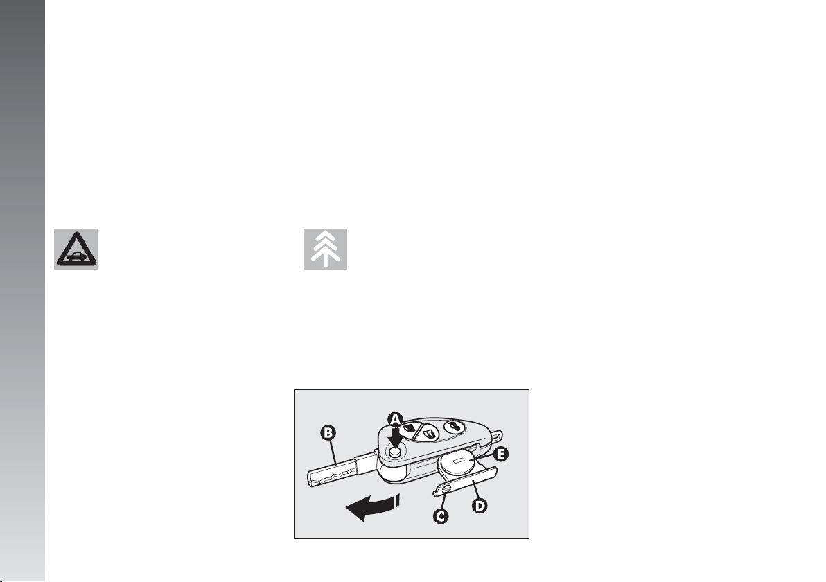
KEY BATTERY
REPLACEMENT
If when pressing button (B, C or D-
fig. 4) the control is rejected or is not per-
formed, the battery should be replaced by
a new one of the same type to be found c/o
normal retailers.
Battery replacement:
– press button (A-fig. 5) and move the
metal insert (B) to the open position;
– using a finely-tipped screwdriver, turn
the opening device (C) and pull out the battery holder (D);
– replace the battery (E) making sure that
the bias is correct;
– re-insert the battery holder in the key
and lock it, turning the device (C).
GETTING TO KNOW YOUR CAR
Should the warning light
turn on at the same time as
the display of the message
“IMMOBILIZ. NOT PROGRAMMED”
on the re-configurable multifunction display, 2 seconds after the ignition key has been set to the position MAR, this means that the
key codes have not been stored,
and hence the car is not protected
against possible theft by the Alfa
Romeo CODE system. In this case
contact the Alfa Romeo Authorized
Service for storing the key codes.
10
Used batteries are harmful to the environment.
They should be disposed of
as specified by law in the special
containers provided. Avoid exposure to naked flames and high temperatures. Keep out of reach of
children.
A0A0006m
fig. 5
Page 12
ELECTRONIC ALARM
(optional for versions/markets
where applicable)
DESCRIPTION
The system comprises: a transmitter, receiver, control unit with siren and volumetric sensors. The electronic alarm is controlled
by the receiver incorporated in the instrument cluster and it is turned on and off by
the remote control in the key which sends
the crypted and variable code. The electronic
alarm controls: the unlawful opening of
doors, bonnet and boot (perimetral protection), operation of the ignition key, battery
cable cutting, the presence of moving bodies in the passenger compartment (volumetric protection) any abnormal raising/
sloping of the car (for versions/markets
where applicable) and central door locking.
It also makes it possible to cut off the volumetric protection.
IMPORTANT The engine inhibitor function is guaranteed by the Alfa Romeo CODE
system which is activated automatically
when the ignition key is removed.
REQUEST FOR ADDITIONAL
KEYS WITH REMOTE CONTROL
The receiver can recognise up to 5 keys
with incorporated remote control. Should a
new key with remote control be necessary
for any reason during the life of the car, contact directly Alfa Romeo Authorised Services,
taking with you the CODE card, a personal
identity document and the car’s ownership
documents.
A0A0010m
HOW TO ACTIVATE THE ALARM
With the doors, bonnet and boot shut and
the ignition key in the STOP or PARKposition (key removed), point the key with remote control in the direction of the car, then
press and release the button (C-fig. 6).
With the exception of certain markets, the
system sounds a “beep” and the doors are
locked.
Engagement of the alarm is preceded by
a self-diagnostic test indicated by a different
flashing frequency of the deterrent led (A-
fig. 7) on the dashboard. If a fault is detected the system sounds a further warning “beep”.
GETTING TO KNOW YOUR CAR
fig. 6
11
Page 13
Surveillance
After switching on, the flashing of the de-
terrent led (A-fig. 7) on the dashboard,
indicates the system surveillance mode. The
led flashes throughout this period.
IMPORTANT Operation of the electronic
alarm is adapted at the origin to the rules
of the different countries.
GETTING TO KNOW YOUR CAR
A0A0005m
Self-diagnostic functions
and door, bonnet, boot control
If, after engaging the alarm, a second
“beep” is sounded, switch off the system
pressing the button (B-fig. 6), check that
the doors, bonnet and tailgate are properly
shut, then switch the system on again pressing the button (C).
Otherwise, the door, bonnet or tailgate that
is not shut properly will be excluded from
the alarm system control.
If the doors, bonnet and boot are shut correctly and the control signal is repeated, the
system self-diagnostics has detected a system operating fault. It is therefore necessary
to contact Authorised Alfa Romeo Services.
HOW TO DEACTIVATE THE
ALARM
To deactivate the alarm press the button (B-
fig. 6) of the key with remote control. The
system will react as follows (with the exception of certain markets):
– two brief flashes of the direction indi-
cators
– two brief “beeps” of the siren
– door unlocking.
IMPORTANT If when the system is
turned off the deterrent led (A-fig. 7) on
the dashboard stays on (maximum 2 minutes or until the ignition key is set to MAR)
the following should be borne in mind:
12
fig. 7
Page 14

– if the led continues flashing, but at different intervals than normal, this means that
different attempts to break in have occurred.
Through the number of flashes it is possible to identify the type of attempt:
1 flash: one or more doors
2 flashes: tailgate
3 flashes: bonnet
4 flashes: ultrasounds
5 flashes: abnormal vehicle lift-
ing/sloping (for versions/markets where applicable)
6 flashes: tampering with car starting
cables
7 flashes: tampering with battery ca-
bles or cutting emergency
key cables
8 flashes: connection line to sensors
and siren
9 flashes: at least three causes of
alarm.
WHEN THE ALARM
IS TRIGGERED
When the system is on, the alarm comes
into action in the following cases:
– opening of one of the doors, bonnet or
tailgate;
– disconnection of the battery or section-
ing of electric cables;
– intrusion in the passenger compartment,
for example breakage of windows (volumetric protection);
– attempt to start the engine (key in
MAR position);
– abnormal car lifting/sloping (for versions/markets where applicable).
Depending on the markets, the cutting in
of the alarm causes operation of the siren
and hazard warning lights (for about 26 seconds). The ways of operating and the number of cycles may vary depending on the
markets.
A maximum number of cycles is however
envisaged.
Once the alarm cycle has ended, the system resumes its normal control function.
VOLUMETRIC PROTECTION
To make sure that the protection system
works correctly the side windows and sunroof (if fitted) must be properly shut.
The function can be cut off (if, for example, leaving animals in the car) carrying out
the following operations in rapid succession:
starting from the condition with the ignition key at MAR, move the key to STOP,
then immediately back to MAR and then
to STOP again, then remove the ignition
key.
The deterrent led (A-fig. 7) on the dashboard lights up for about 2 seconds to confirm that the function has been cut off.
To restore volumetric protection, move and
keep the ignition key at MAR for over 30
seconds.
If, with the volumetric protection function
deactivated, an electric control controlled by
the ignition key at MAR is required (e.g.
power windows) turn the key to MAR, operate the control and move the key to
STOP in a maximum time of 30 seconds.
This way volumetric protection is not restored.
GETTING TO KNOW YOUR CAR
13
Page 15
HOW TO CUT OFF
THE ALARM SYSTEM
To deactivate the alarm system completely (for instance during prolonged inactivity
of the vehicle) simply lock the car turning
the key in the lock.
MINISTERIAL CERTIFICATION
In accordance with the law in force in each
country, on the subject of radio frequency,
we wish to point out that for the markets in
which the transmitter needs to be marked,
the certification number is given on the com-
GETTING TO KNOW YOUR CAR
ponent.
Depending on the versions/markets, the
code may also be given on the transmitter
and/or on the receiver.
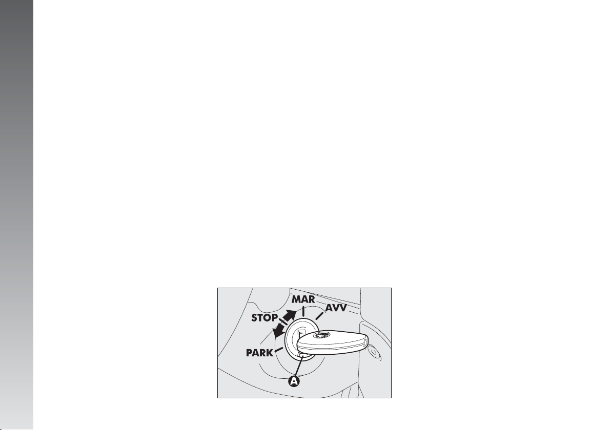
IGNITION DEVICE
SWITCH
The key can be turned to one of four po-
sitions:
– STOP: engine switched off, key can be
removed, engine inhibitor engaged, steering lock engaged, services excluded apart
from those supplied directly (e.g. hazard
warning lights).
– MAR: drive position. The engine lock
is deactivated and all electrical devices are
powered.
IMPORTANT Do not leave the key in
this position when the engine is stopped.
– AVV: instable position for starting the
engine.
(fig. 8)
A0A0016m
IMPORTANT If the engine fails to start
move the key back to STOP and repeat.
The ignition switch has a safety device
which prevents passage to AVV when the
engine is running.
– PARK: engine switched off, key can
be removed, engine lock engaged, steering lock engaged, sidelights switched on automatically.
IMPORTANT To turn the key to the
PARK position, button (A) on the switch
must be pressed first.
14
fig. 8
Page 16
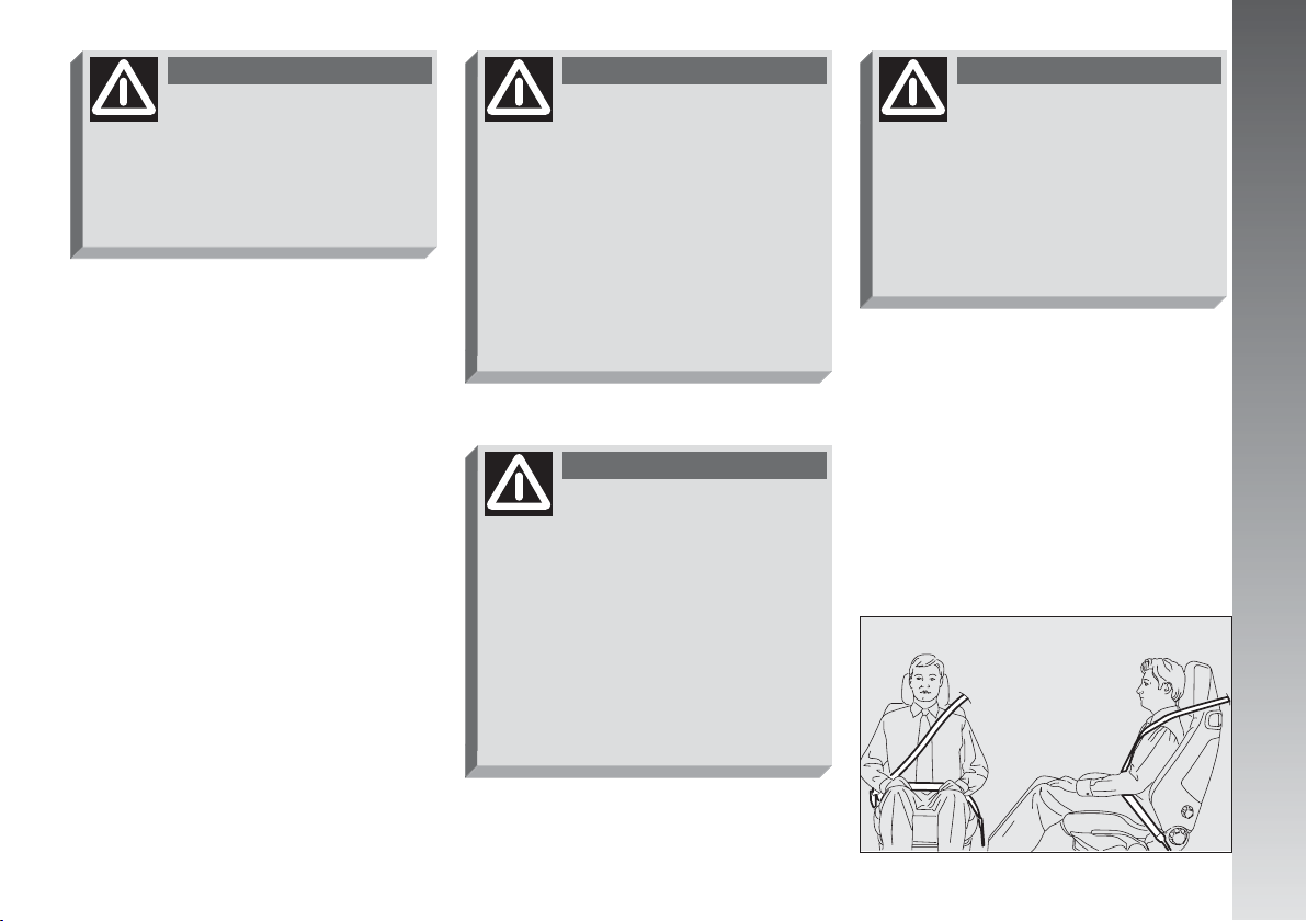
WARNING
When leaving the vehicle
always remove the key
from the ignition to prevent any occupants of the vehicle from accidentally activating the controls.
Never leave children in the vehicle unaccompanied. Remember to
engage the handbrake, and, if the
vehicle is parked on an uphill slope,
to engage first gear. If the vehicle
is facing downhill, engage reverse
gear.
If the ignition device is
tampered with (for example an attempted theft)
have it checked over by Alfa
Romeo Authorised Services before
travelling again.
STEERING LOCK
Engaging:
– move the key to STOP orPARK, then
remove the key and turn the steering wheel
slightly to facilitate the locking action.
Disengaging:
– turn the key to MAR gently rocking the
steering wheel from side to side.
WARNING
Never remove the ignition
key with the car on the
move. The steering wheel would
lock automatically the first time the
steering wheel is turned. This also occurs if the car is towed.
WARNING
It is absolutely forbidden to
carry out whatever aftermarket operation involving steering
system or steering column modifications (e.g.: installation of antitheft device) that could badly affect
performance and safety, cause the
lapse of warranty and also result in
non-compliance of the car with homologation requirements.
DOORS
WARNING
Before opening a door, always make sure that it can
be done safely.
OPENING/CLOSING FROM
OUTSIDE
To open the driver's door turn the key
clockwise and to open the passengers' door,
optional for versions/markets where applicable, turn the key anti-clockwise, then
remove the key and press the button (A-
fig. 9).
To close the door, turn the key in the lock
in the opposite direction to the one for opening.
A0A0017m
GETTING TO KNOW YOUR CAR
fig. 9
15
Page 17

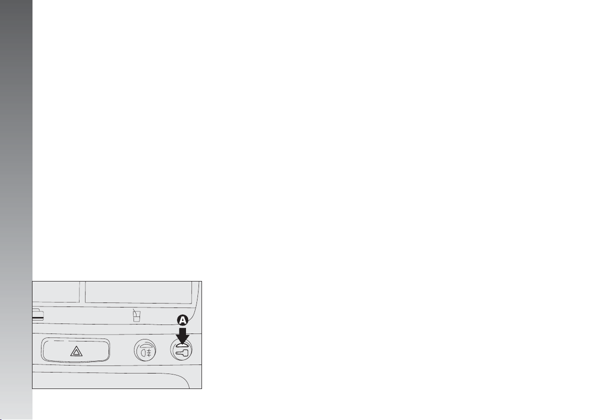
OPENING/CLOSING
FROM INSIDE
To open the door, pull the handle
(A-fig. 10).
To close the door, pull it; then to prevent
opening from outside, press the button (A-
fig. 11) on the dashboard, the deterrent
led (B) on the actual button lights up with
a yellow light to confirm that locking has
taken place.
GETTING TO KNOW YOUR CAR
CENTRAL LOCKING
This allows central locking of the door
locks.
To engage central locking, the doors must
be perfectly shut, otherwise, locking is denied.
IMPORTANT With central locking engaged, pulling the inside lever for opening
one of the doors causes the unlocking also
of the other door.
In the event of a power cut off (blown
fuse, battery disconnected, etc.) it is still possible to work the lock by hand.
FRONT SEATS
WARNING
Any adjustments are to be
carried out only with the
vehicle stationary.
A0A0409m
16
fig. 10
A0A0018m
fig. 11
A0A0019m
fig. 12
Page 18
LENGTHWISE ADJUSTMENT
(fig. 12)
Raise the lever (A) and push the seat
backwards or forwards; in the driving position the arms should be slightly flexed and
the hands should rest on the rim of the steering wheel.
WARNING
After releasing the adjust-
ment lever, always check
that the seat is locked on the runners, trying to move it to and from.
The lack of this clamping action
could cause the seat to move unexpectedly and cause loss of vehicle control.
DRIVER’S SEAT HEIGHT
ADJUSTMENT
To raise the seat, pull the lever (B) up-
wards, then work the lever (up and down)
until reaching the required height, then release it. To lower the seat, push the lever
(B) downwards then work the lever (up and
down) until reaching the required height.
IMPORTANT Adjustment must be car-
ried out only seated in the driver’s seat.
BACK REST ANGLE
ADJUSTMENT
Turn the knob (C) until reaching the posi-
tion required.
(fig. 12)
(fig. 12)
TILTING THE BACK REST
(fig. 12)
To gain access to the rear seats, pull the
handle (E), the back rest folds and the seat
is free to run forwards.
A recovery mechanism with memory
makes it possible to take the seat back to
its previous position.
Once the seat back has been returned to
the travelling condition, make sure that it
is correctly clamped, checking that the “red
band” on the upper part of the handle (E)
is concealed. In fact, this “red band” indicates that the seat back is not camped.
Also check that the seat is firmly locked on
the runners, trying to move it to and from.
DRIVER’S SEAT LUMBAR
ADJUSTMENT
Turn the knob (D) until obtaining the most
comfortable position.
(fig. 12)
GETTING TO KNOW YOUR CAR
17
Page 19
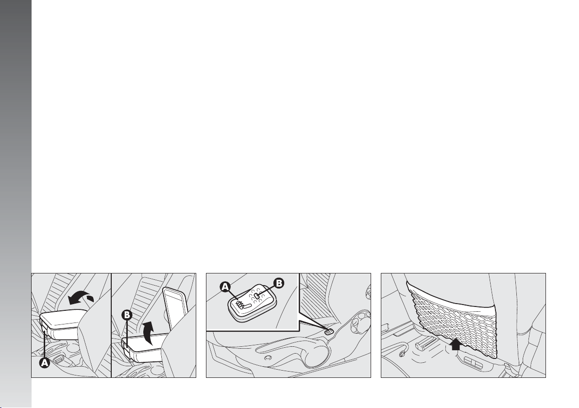
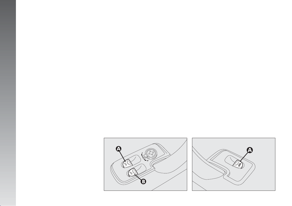
CENTRAL ARMREST
(fig. 13)
The armrest is adjustable and can be raised
or lowered to the required position.
To adjust, slightly raise the armrest, then
press the release device (A).
Inside the armrest there is an oddments
compartment, to use it, raise the cover,
pressing the device (B).
GETTING TO KNOW YOUR CAR
SEAT WARMING
(fig. 14)
(optional for versions/markets
where applicable)
The seat warming pad can be switched on
and off using switch (A) on the outer side
of the seat.
Switching on is shown by the lighting up
of the led (B) on the switch itself.
REAR POCKETS
(fig. 15)
(for versions/markets
where applicable)
The front seats are fitted with a pocket in
the rear of the back rest.
18
fig. 13
A0A0412m
fig. 14
A0A0485m
A0A0413m
fig. 15
Page 20
REAR SEATS
EXTENDING THE
LUGGAGE COMPARTMENT
The split rear seat makes it possible to extend the luggage compartment totally or partially, acting separately on one of the two
parts, thereby offering different possibilities
of load depending on the number of rear
passengers.
WARNING
If a particularly heavy load
is placed in the boot, when
travelling at night, it is wise to
check the height of the high beams
(see “Headlamps” paragraph).
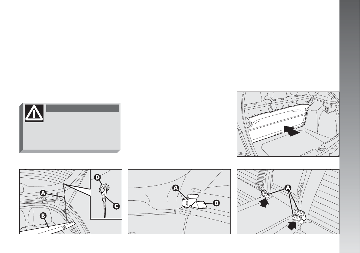
Removing the rear parcel shelf
Proceed as follows:
– free the ends of the two rods (A-fig.
16) supporting the parcel shelf (B) pulling
the eyelets (C) off the pins (D);
– release the pins (A-fig. 17) at the out-
side of the shelf from their housings (B) obtained in the side supports, then remove the
shelf pulling it outwards.
After removal the shelf can be placed in
two ways:
– crossways in the luggage compartment
as shown in fig. 18;
– crossways between the front seat back
reats and the tilted cushions of the rear seats
if the boot is extended totally (see fig. 22).
Total extension
Proceed as follows:
– position the seat belt buckles (A-fig.
19) in their housings in the cushion;
– pull the handles in the centre of the cush-
ions, then tilt them forwards;
A0A0415m
GETTING TO KNOW YOUR CAR
fig. 16
A0A0414m
fig. 17
A0A0028m
fig. 18
fig. 19
A0A0416m
19
Page 21
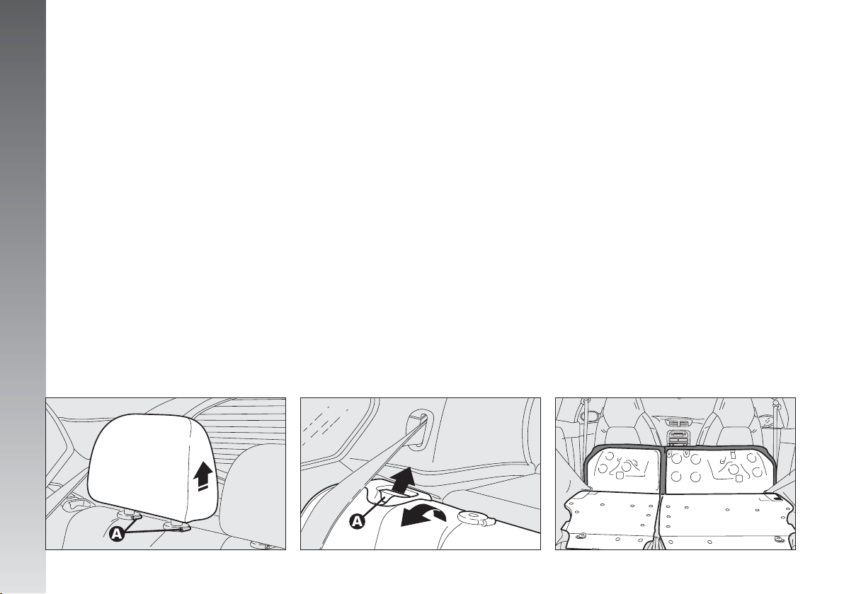
– raise the headrests to the highest posi-
tion, press both buttons (A-fig. 20) at the
side of the two supports, then remove the
headrests pulling them upwards.
– move the seat belts to the side extend-
ing them correctly without twisting;
– raise the levers (A-fig. 21) retaining
the back rests and tilt them forwards to obtain a single loading surface (fig. 22).
IMPORTANT For versions/markets
where applicable, the retainer levers are replaced by buttons (one for each side). To release the back rests and tilt them, use the
GETTING TO KNOW YOUR CAR
buttons themselves.
Partial extension
For partial extension, proceed as follows:
– tilt the cushion required pulling the handle at the centre of the cushion, then tilting the actual cushion;
– raise the headrests of the seat to be tilted to the highest position, press both buttons at the side of the two supports and remove the headrests pulling them upwards;
– move the seat belt to one side extending it correctly without twisting;
– raise the lever retaining the back rest
and tilt it forwards.
To bring the seat back to its
normal position
Proceed as follows:
– move the seat belts to the side extend-
ing them correctly without twisting;
– raise the seat backs, pushing them backwards until hearing both clamping devices
click into place, checking that the “red
band” can no longer be seen on the upper
part of the levers (A-fig. 21). In fact, this
“red band” indicates that the seat back is
not clamped;
– set the cushions to the horizontal position keeping the centre seat belt raised;
– refit the headrests.
20
fig. 20
A0A0469m
fig. 21
A0A0031m
A0A0470m
fig. 22
Page 22
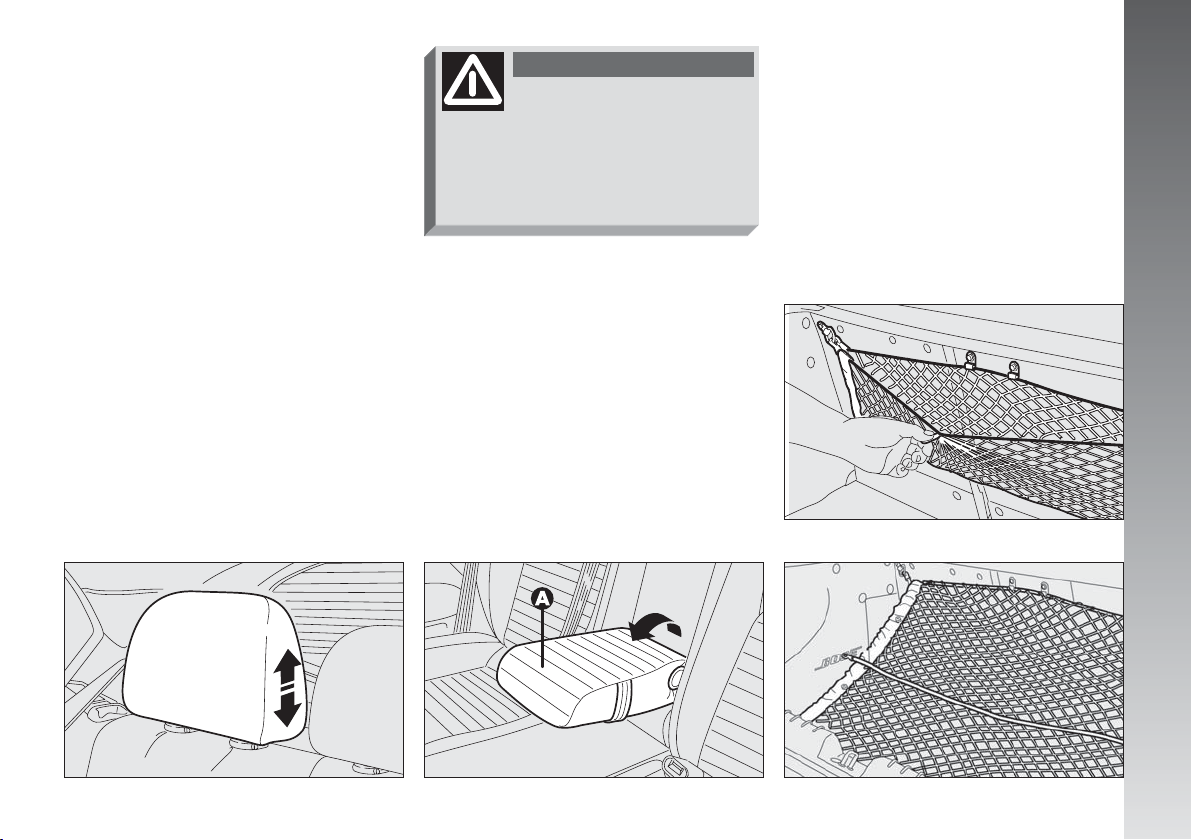
HEADREST ADJUSTMENT
(fig. 23)
The car may be fitted with two headrests
for the side seats and, depending on the trim
level, it may also have a third headrest in
the centre.
The headrests have 2 positions
(up/down) depending on the height of the
passenger.
In the case of need, it is possible to remove
the headrests as described previously (see
“Luggage compartment extension”).
WARNING
Remember that headrests
should be adjusted so that
the nape, and not the neck, rests
on them. Only in this position do
they exert their protective action
in the event of a crash from behind.
CENTRAL ARMREST
(fig. 24)
To use the armrest (A), lower it as illus-
trated.
LUGGAGE
RETAINER NET
Present only on certain versions, the interior fittings are completed by the luggage retainer net, which is helpful in correctly arranging the load and/or suitable for transporting light materials.
Fig. 25, 26, 27 below show the various
clamping solutions for the net in the boot.
A0A0326m
GETTING TO KNOW YOUR CAR
fig. 23
A0A0417m
fig. 24
A0A0418m
fig. 25
fig. 26
A0A0327m
21
Page 23
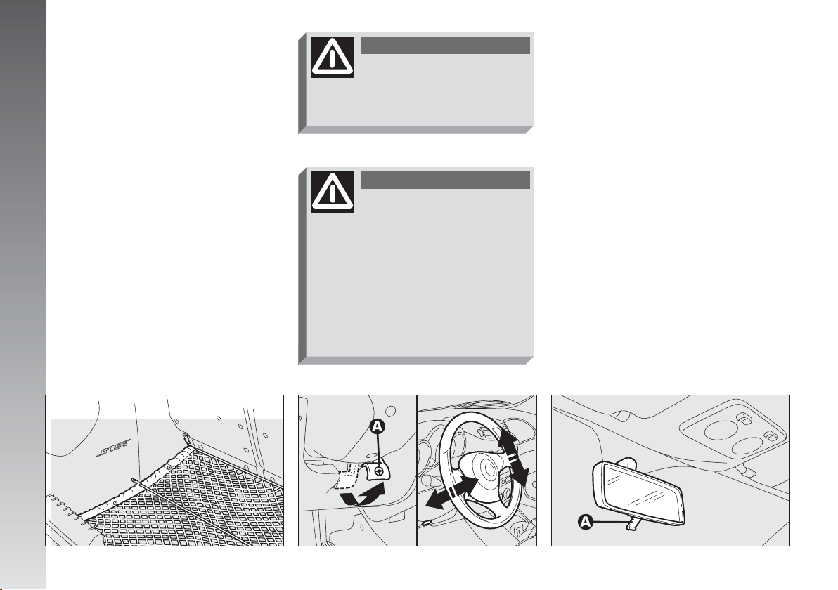
STEERING WHEEL
ADJUSTMENTS
The driver can adjust the steering wheel
position in rake and height.
To do this, release the lever (A-fig. 28)
pulling it towards the steering wheel.
After moving the steering wheel to the
most suitable position, lock it pushing the
lever fully forwards.
GETTING TO KNOW YOUR CAR
WARNING
Any adjustment of the
steering wheel position
must be carried out only with the
vehicle stationary.
WARNING
It is absolutely forbidden to
carry out whatever aftermarket operation involving steering
system or steering column modifications (e.g.: installation of antitheft device) that could badly affect
performance and safety, cause the
lapse of warranty and also result in
non-compliance of the car with homologation requirements.
REAR-VIEW MIRROR
ADJUSTMENT
INNER
The mirror, fitted with a safety device that
causes it to be released in the event of a
violent crash, can be moved using the lever
(A-fig. 29) to two different positions normal or antiglare.
22
fig. 27
A0A0328m
fig. 28
A0A0038m
A0A0039m
fig. 29
Page 24
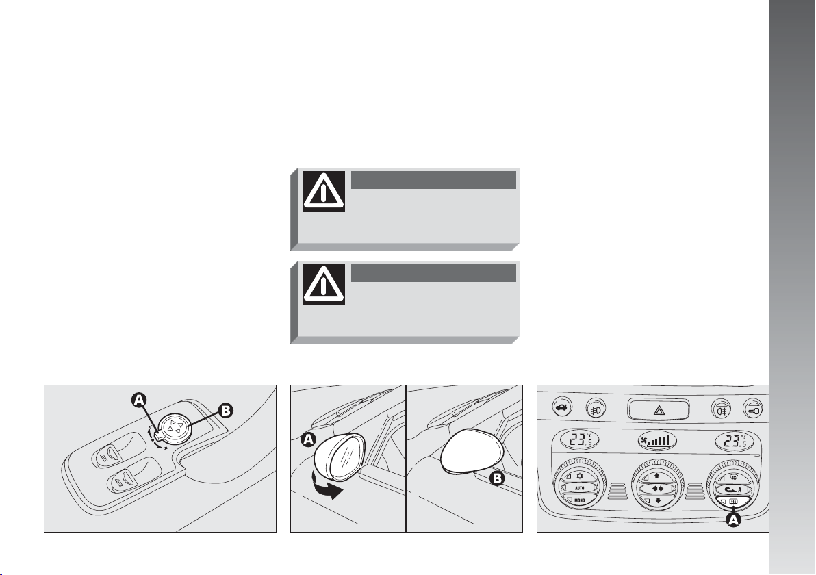
OUTER
Electric adjustment (fig. 30)
– use the switch (A) to select the mirror
required (right or left);
– pressing the button (B), in one of the
four directions, move the mirror selected previously;
– Position the switch (A) in the interme-
diate locking position.
IMPORTANT Adjustment is possible on-
ly with the ignition key at MAR.
Folding (fig. 31)
– In the event of need (for example when
the mirror causes difficulty in narrow spaces)
it is possible to fold the mirror moving it from
position (A) to position (B).
WARNING
When driving the mirrors
should always be in posi-
tion (A).
WARNING
As the driver’s wing mirror
is curved, it may slightly
alter the perception of distance.
Defrosting/demisting (fig. 32)
The electric mirrors are fitted with heat-
ing coils which come into operation with
rearscreen heating pressing the button (A)
thereby defrosting and/or demisting the mirrors.
IMPORTANT The function is timed and
automatically switched off after a few minutes.
GETTING TO KNOW YOUR CAR
fig. 30
A0A0040m
fig. 31
A0A0041m
fig. 32
A0A0486m
23
Page 25
POWER WINDOWS
The power windows are fitted with a safety system with crush-prevention seals. The
electronic control unit that operates the system is capable of detecting the presence of
an obstacle during the window closing motion through the special seals. Should this
occur, the system stops the movement of
the window and reverses it immediately.
IMPORTANT If the crush-prevention
function is operated for 3 times in 1 minute,
the system automatically sets to the recov-
GETTING TO KNOW YOUR CAR
ery mode (self-protection). To reset the correct system operating logic, use the control
button. The window will rise in predefined
steps until closing completely. The logic is
reset and if there are no faults, the window
winder automatically resumes normal operation; if not, contact Alfa Romeo Authorised Services.
IMPORTANT With the ignition key at
STOP or removed, the power windows re-
main activated for about 3 minutes and are
deactivated immediately the moment a door
is opened.
Driver’s side (fig. 33)
The driver’s door panel contains the but-
tons that control the following windows,
with the ignition key at MAR:
A - left front window
B - right front window.
Press the button to lower the window. Pull
to raise it.
IMPORTANT The driver’s power window
is fitted with the “continuous automatic operation” device for both lowering and raising
the window. A brief press on the upper or
lower part of the button will cause it to move
and continue automatically: the window
stops in the required position by pressing either the upper or lower part of the button
again.
A0A0043m
Passenger’s side (fig. 34)
The button (A) controls the passenger’s
side window.
IMPORTANT The passenger side pow-
er window is provided with an “automatic
continuous operation” device both to lower and to raise the window. A brief push on
the upper or lower part of the button is sufficient to start the run which continues automatically: the window stops at the required position by pushing once again indifferently the upper or lower part of the button.
A0A0044m
24
fig. 33
fig. 34
Page 26
WARNING
Improper use of power
windows can be dangerous. Before and during use, always
make sure that the passengers are
not exposed to the risk of harm either directly by the moving windows or by personal objects drawn
or knocked by them. When leaving
the car, always remove the ignition
key to prevent the power windows
from being operated inadvertently, and harming anyone left on
board.
Do not keep the button
pressed when the window
is completely raised or
lowered.
IMPORTANT After locking the doors,
keeping the corresponding button of the remote control pressed for about 2 seconds
causes automatic closing of the windows
and sunroof (if present). The remote control
button should be pressed until the windows
have completed their stroke; releasing the
button sooner, the windows stop in the position they are in at that moment.
On all versions, after unlocking the doors,
keeping the remote control button pressed
for about 2 seconds the windows and sunroof (if present) are opened.
SEAT BELTS
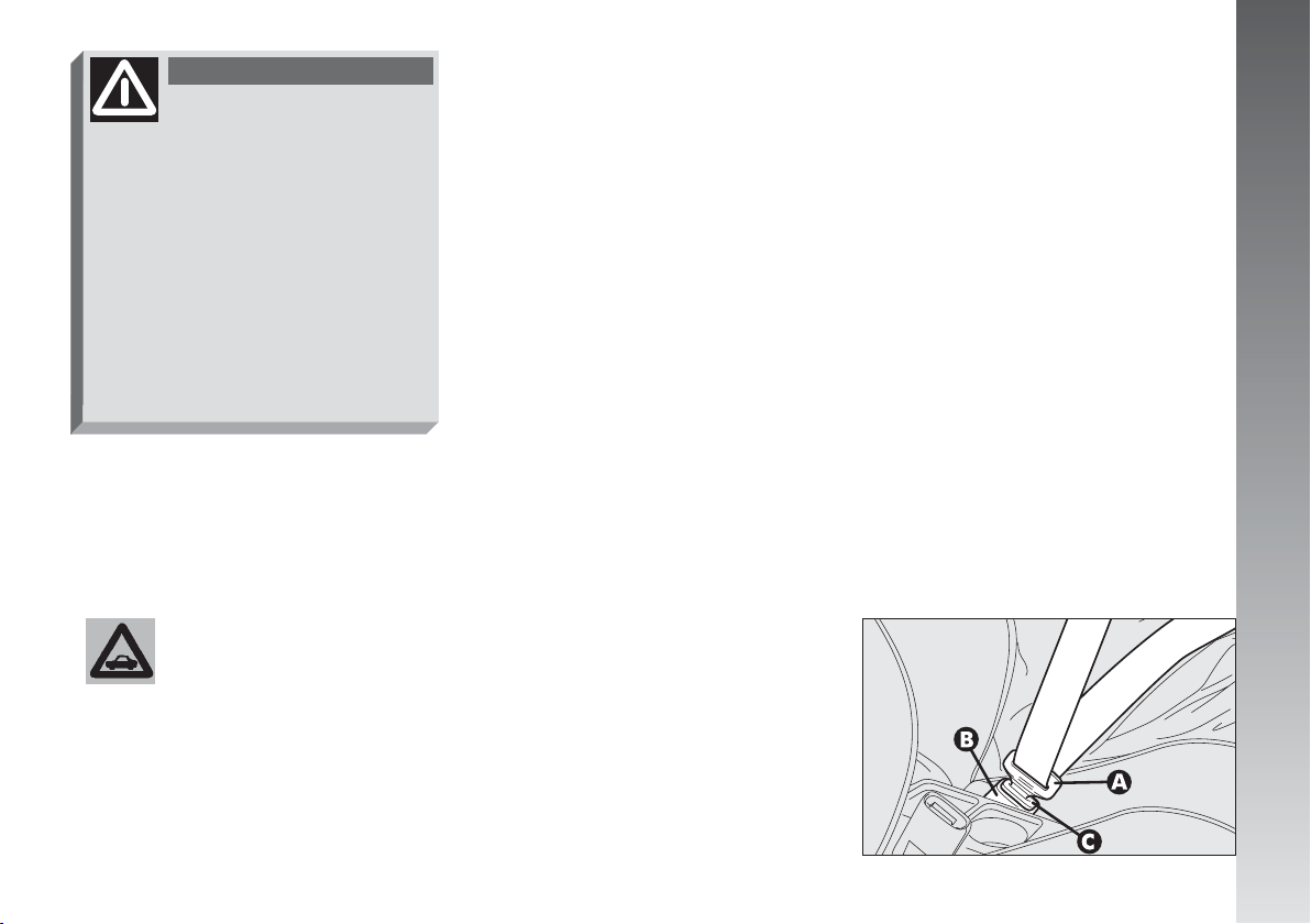
USING THE SEAT BELTS
The belt should be worn keeping the chest
straight and rested against the seat back.
Take hold the tongue (A-fig. 35) and in-
sert it into the buckle (B), until hearing the
locking click.
At removal, if it jams, let it rewind for a
short stretch, then pull it out again without
jerking.
GETTING TO KNOW YOUR CAR
A0A0045m
fig. 35
25
Page 27
To unfasten the seat belts, press button
(C). Guide the seat belt with your hand while
it is rewinding, to prevent it from twisting.
WARNING
Never press button (C)
when travelling.
GETTING TO KNOW YOUR CAR
Through the reel, the belt automatically
adapts to the body of the passenger wearing it, allowing freedom of movement.
When the car is parked on a steep slope
the reel mechanism may block; this is normal. The reel mechanism prevents the webbing coming out when it is jerked or if the
car brakes sharply, in a collision or when cornering at high speed.
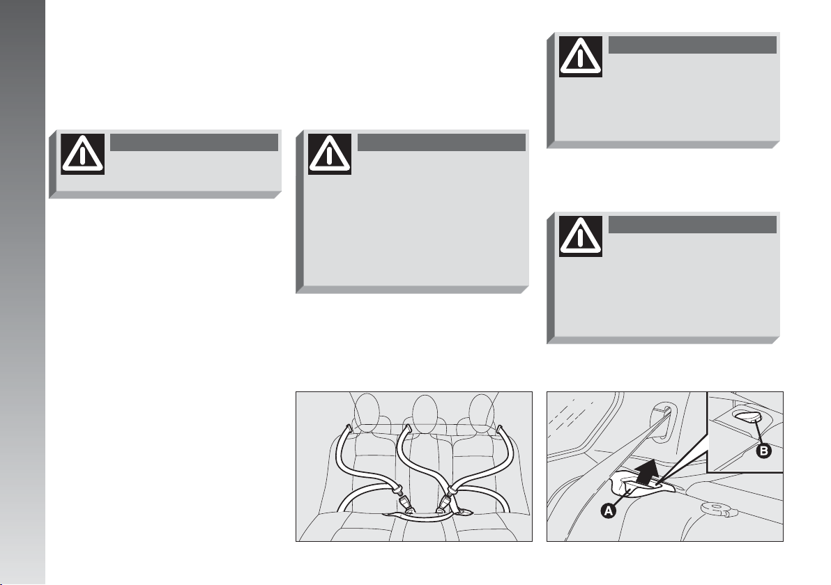
The rear seat is fitted with inertial seat belts
with three anchor points with reel for the
side seats and for the centre seat (fig. 36).
WARNING
When the seat back is cou-
pled properly, the “red
band” (B) next to the seat back
levers (A) disappears. The “red
band” actually indicates improper
seat back coupling (fig. 36a). When
resetting it in proper position,
make sure to hear the locking click.
A0A0386m
WARNING
After tilting, when reset-
ting the rear seat in
straight position, take care to reposition the seat belt properly to
have it ready for use.
WARNING
Make sure the seat back is
correctly hooked on both
sides (not visible “red bands” (B))
to prevent seat back being thrown
forwards and injuring passengers
should you brake sharply.
A0A0708m
26
fig. 36
fig. 36a
Page 28
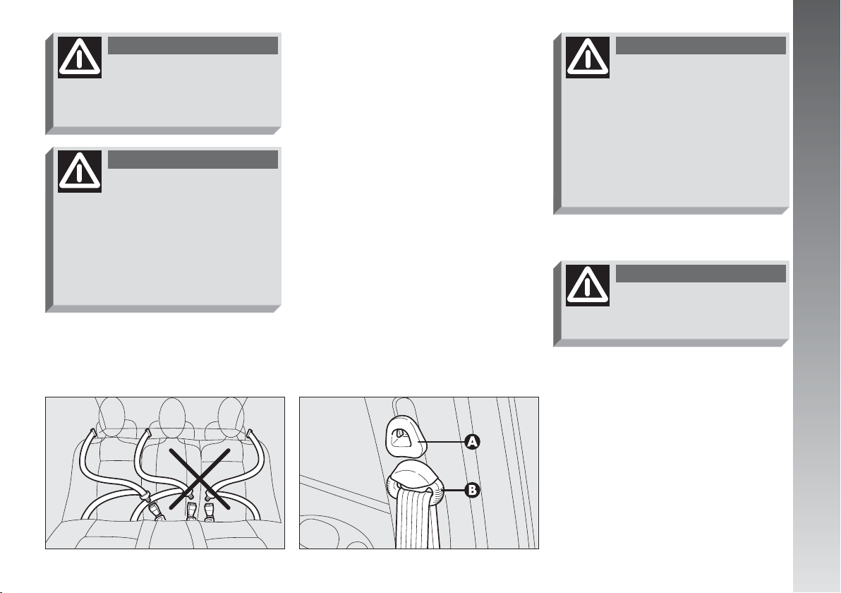
WARNING
To offer the highest level of
protection, the rear seat
belts should be fastened as shown
in fig. 36.
WARNING
Remember that, in the
event of an accident, any
passengers occupying the rear
seats who are not wearing a seat
belt not only subject themselves to
great personal risk but constitute
a danger to the occupants of the
front seats.
When the rear seats are not occupied, use
the spaces provided in the cushion to stow
the belt buckles.
FRONT SEAT BELT HEIGHT
ADJUSTMENT
The front seat belt ring can take different
positions which make it possible to adjust
the height of the belts.
Always adjust the height of the belts adapting it to the person who is wearing it. This
precaution improves their effectiveness. substantially reducing the risk of injury in the
event of a crash.
Correct adjustment is obtained when the
belt passes half way between the end of the
shoulder and the neck.
To adjust, lower or raise the grip (A-
fig. 38) of the locking device, at the same
time moving the ring (B) to the most appropriate of the allowed positions.
WARNING
After adjustment, always
check that the slider (Bfig. 38) is anchored in one of the
positions provided. To do this, with
the button (A-fig. 38) released, exert a further pressure to allow the
anchor device to catch if release did
not take place at one of the preset positions.
GETTING TO KNOW YOUR CAR
WARNING
Make the height adjust-
ment when the car is stationary.
fig. 37
A0A0387m
fig. 47
A0A0419m
LOAD LIMITERS
To increase passive safety, the front seat
belt reels contain a load limiter which allows
controlled sag in such a way as to dose the
force acting on the shoulders during the belt
restraining action.
27
Page 29
PRE-TENSIONING DEVICES
To increase the efficiency of the front seat
belts, Alfa 147 GTA is fitted with pre-
tensioning devices.
These devices “feel” that the car is being
subject to a violent impact by way of a sensor rewind the seat belts a few centimetres.
In this way they ensure that the seat belt
adheres to the wearer before the restraining
action begins.
The seat belt locks to indicate that the device has intervened; the seat belt cannot be
drawn back up even when guiding it man-
GETTING TO KNOW YOUR CAR
ually.
IMPORTANT The pretensioner will give
maximum protection when the seat belt adheres snugly to wearer’s chest and hips.
Front seat pretensioners activate only if
front seat belts are properly fitted into buckles.
A small amount of smoke may be produced. This smoke is in no way toxic and
presents no fire hazard.
The emergency tensioning retractor needs
no maintenance or lubrication. Any modification to its original features will nullify the
retractor’s effectiveness. If, due to unusual
natural events (floods, high waves, etc.),
the device has been affected by water and
mud, it must be replaced.
WARNING
The pretensioner can only
be used once. After a collision that has triggered it, have it
replaced at Alfa Romeo Authorized
Service. The validity of the device
is written on the plate located on
the front left door near the lock.
Contact Alfa Romeo Authorized
Services to have pretensioner replaced as this date approaches.
Operations involving
banging, vibrations or
heating (above 100°C for
a maximum of 6 hours) in the area
of the pretensioners may damage
or trigger off the device. Vibrations
from rough road surfaces or accidental jolting caused by mounting
pavements etc. do not have any effect on the pretensioner. If, however, you need assistance, go to Alfa Romeo Authorized Services.
28
Page 30
WARNING
Never disassemble or tam-
per with the pretensioner
components. All interventions must
be carried out by qualified and authorised personnel. Always contact
Alfa Romeo Authorized Services.
WARNING
To ensure the highest de-
gree of protection, you are
recommended to keep the seat
backrest in the straightest position
possible, and the belt adhering well
to the chest and pelvis. Seat belt
should always be worn in both the
front and rear positions! Travelling
without seat belt increases the risk
of serious injury or death in the
case of accident.
WARNING
Under no circumstances
should the components of
the seat belts and pretensioner be
tampered with or removed. Any
operation should be carried out by
qualified and authorised personnel.
Always contact an Alfa Romeo Authorized Service.
GETTING TO KNOW YOUR CAR
GENERAL INSTRUCTIONS
FOR THE USE OF THE
SEAT BELTS
All the occupants of the car are obliged to
respect the local traffic laws regarding the
wearing of seat belts.
Always fasten the seat belts before starting.
WARNING
The seat belt must not be
twisted and should cling
tightly to the body. The upper part
must pass over the shoulder and
diagonally across the chest. The
lower part must rest across the
pelvis and not across the stomach
to eliminate the risk of sliding forwards (fig. 39). Do not use devices
(clips, stoppers, etc.) which keep
the belts away from the body.
fig. 39
A0A0420m
29
Page 31

WARNING
If the seat belt has been
subjected to shock, for example during an accident, it must
be completely replaced together
with the attachments and their
screws, and the pretensioning devices, even if visible defects are not
detected as the belt may have lost
its resilience.
GETTING TO KNOW YOUR CAR
WARNING
Do not carry children on
your knee using a single
seat belt for both (fig. 40). Do not
fasten other objects to the body.
Seat belts are also to be worn by expectant mothers: the risk of injury in the case
of accident is greatly reduced for them and
the unborn child if they are wearing a seat
belt.
Pregnant women must of course position
the lower part of the belt very low down so
that it passes under the abdomen (fig. 41).
HOW TO KEEP THE SEAT BELTS
ALWAYS IN EFFICIENT
CONDITIONS
– Always use the belts with the tape well
taut and never twisted; make sure that it
is free to run without impediments.
A0A0421m
– After a serious accident, replace the belt
being worn at that time, even if it does not
appear damaged. Always replace the seat
belts if pretensioners have been activated.
– To clean the belts, wash by hand with
neutral soap, rinse and leave to dry in the
shade. Never use strong detergents, bleach
or dyes or any other chemical substance that
might weaken the fibres.
– Prevent the reels from getting wet: correct operation of them is only guaranteed
if water does not get inside.
– Replace the seat belt if it shows significant wear or cut signs.
A0A0422m
30
fig. 40
fig. 41
Page 32

CARRYING CHILDREN SAFELY
WARNING
SERIOUS DANGER! Never place cradle child’s seats on the
front passenger seats of cars equipped with passenger air
bag since the air bag activation could cause serious injuries, even mortal.
You are advised to carry children always on the rear seat, as this is the
most protected position in the case of a crash. In any case, child’s seats
must absolutely not be positioned on the front seat of car’s with passenger’s air bag, which during inflation could cause serious injury, even mortal, regardless of the seriousness of the crash that triggered it. Children
may placed on the front seat of cars fitted with passenger’s air bag deactivation. In this case, it is absolutely necessary to check the warning light
F
on dial to make sure that deactivation has actually took place (see paragraph “Front and side air bags“ at item “Front passenger air bag“). The
front passenger seat shall be adjusted in the most backward position to
prevent any contact between the child’s seat and the dashboard.
For the best level of protection in the event
of a crash, all occupants must travel seated
and secured by suitable restraint systems.
This is even more important for children.
According to 2003/20/EC Directive, this
prescription is compulsory for all European
Community countries.
Compared with adults, a child’s head is proportionately larger and heavier than the rest
of the body, while muscles and bone structure are not completely developed. Therefore, in order to restraint them correctly in
the event of a crash, different systems are
needed then adult seat belts.
A0A0388m
GETTING TO KNOW YOUR CAR
fig. 42
31
Page 33

The results of research on the best protection for a child are summarised in European Standard ECE-R44, which in addition
to making them compulsory, subdivides restraint systems into five groups:
Group 0 until 10 kg in weight
Group 0+ until 13 kg in weight
Group 1 9-18 kg in weight
Group 2 15-25 kg in weight
Group 3 22-36 kg in weight
As it may be noted, the groups partially
GETTING TO KNOW YOUR CAR
overlap and in fact, in commerce it is possible to find devices that cover more than
one weight group (fig. 42).
All the restraint devices must bear the homologation data, together with the control
brand, on a solidly fixed label which must
absolutely not be removed.
Over 1.50 m in height, from the point of
view of restraint systems, children are considered as adults and wear belts normally.
The Lineaccessori Alfa Romeo includes
seats for each weight group, which are the
recommended choice because they have
been designed and specifically experimented for Alfa Romeo cars.
GROUP 0 and 0+
Babies up to 13 kg must be carried fac-
ing behind (fig. 43) on a cradle seat,
which, supporting the head, does not induce
strain on the neck in the event of sharp deceleration.
The cradle is restrained by the car safety
belts, as illustrated, and it should in turn
restrain the child with the belts incorporated on it.
WARNING
The illustration is indica-
tive only for assembly. Assemble the seat according to the
compulsory instructions provided
with it.
A0A0389m
GROUP 1
Starting from 9 kg to 18 kg in weight, chil-
dren may be carried facing forwards with
seats fitted with front cushion (fig. 44),
through which the car seat belt restrains both
child and seat.
WARNING
The illustration is indica-
tive only for assembly. Assemble the seat according to the
compulsory instructions provided
with it.
A0A0390m
32
fig. 43
fig. 44
Page 34

WARNING
Seats exist which are suit-
able for covering weight
groups 0 and 1 with a rear connection to the car belts and its own
belts to restrain the child. Because
of their mass, they can be dangerous if installed incorrectly fastened
to the car belts with a cushion.
Strictly adhere to the assembly instructions provided.
GROUP 2
Starting from 15 to 25 kg in weight, children may be restrained directly by the car
seat belts. Child seats only have the function of positioning the child correctly in relation to the belts, so that the diagonal part
adheres to the chest and never to the neck
and that the horizontal part adheres to the
child’s pelvis and not to the abdomen (fig.
45).
WARNING
The illustration is indica-
tive only for assembly. Assemble the seat according to the
compulsory instructions provided
with it.
GROUP 3
For children from 22 kg up to 36 kg the
child’s chest is thick enough not to need the
spacer back rest any more.
fig. 46 shows proper child seat positioning on the rear seat.
Over 1.50 m in height, children may wear
seat belts like adults.
GETTING TO KNOW YOUR CAR
WARNING
The illustration is indica-
tive only for assembly. Assemble the seat according to the
compulsory instructions provided
with it.
fig. 45
A0A0391m
fig. 46
A0A0392m
33
Page 35

PASSENGER SEAT COMPLIANCE WITH REGULATIONS ON CHILD’S SEAT USE
Alfa 147 GTA complies with the new EC Directive 2000/3 regulating child’s seat assembling on the different car seats according to
the following table:
Versions rear seats
Group Range of weight SEAT
GETTING TO KNOW YOUR CAR
Group 0,0+
Group 1
Group 2
Group 3
Key:
U = suitable for child restraint systems of the “Universal“ category, according to European Standard ECE-R44 for the specified “Groups“
L = suitable for certain child’s restraint systems available at Lineaccessori Alfa Romeo for the specified group
34
0 - 13 kg
9 -18 kg
15 - 25 kg
22 - 36 kg
Front passenger Rear side Rear centre
L
L
L
L
passenger seat passenger seat
U
U
U
U
(inertial seat belt with
three anchor points)
U
U
U
U
Page 36

Below is a summary of the safety rules to be observed when carrying children:
1) The recommended position for in-
stalling a child’s seat is on the rear seat, as
it is the most protected in the event of a
crash.
WARNING
If a passenger’s air bag is
installed, children should
never travel on the front seat.
4) Always pull the tape to check that the
belts are buckled.
5) All restraint systems are strictly for one
child only: never use for two children at the
same time.
6) Always make sure that the belts do not
rest on the child’s neck.
7) During the journey, do not allow the
child to stay in abnormal positions or release
the belts.
8) Do not carry children in your arms, not
even small babies. No-one, however strong,
can keep hold of them in a crash.
9) In the case of accidents, replace the
child’s seat with a new one.
FRONT AND SIDE
AIR BAGS
The car is fitted with front Air bags for the
driver (fig. 47), for the passenger (fig.
48), side bags (fig. 49) and window bags
(fig. 50).
A0A0487m
GETTING TO KNOW YOUR CAR
2) If the passenger’s Air bag is deactivat-
ed always, check the warning light
on the cluster to make sure that it has actually been deactivated.
3) Carefully follow the instructions pro-
vided with the child’s seat, which the supplier is obliged to attach. Keep them in the
car together with the documents and this
booklet. Do not use used seats without the
instructions for use.
F
fig. 47
fig. 48
A0A0488m
35
Page 37

FRONT AIR BAGS
Description and operation
The front Air bag (driver’s and passenger’s)
is a safety device which comes into action
in the event of a head-on collision.
GETTING TO KNOW YOUR CAR
fig. 49
A0A0423m
A0A0424m
It is formed of a cushion that inflates in-
stantaneously contained in a special recess:
– in the centre of the steering wheel for
the driver;
– in the dashboard and with a bigger cush-
ion for the passenger.
The front Air bag (driver’s and passenger’s)
has been designed to protect the occupants
in the event of head-on crashes of mediumhigh severity, by placing the cushion between the occupant and the steering wheel
or dashboard.
In the case of a crash, an electronic control unit processes the signals leading from
a deceleration sensor and, when necessary
triggers inflation of the cushion.
The cushion inflates instantaneously, setting itself between the body of the front occupants and the structures that could cause
injury. The cushion then deflates immediately afterwards.
The front air bag (driver’s and passenger’s)
does not replace but is complementary to
the use of belts, which should always be
worn, as specified by law in Europe and
most non-European countries.
In the event of a crash a person that is not
wearing the seat belt moves forwards and
may come into contact with the cushion
while it is still opening. Under these circumstances the protection offered by the
cushion is reduced.
Front air bags designeed to protect car’s
occupants in front crashes and therefore nonactivation in other types of collusions (side
collisions, rear-end shunts, roll-overs, etc...)
is not a system malfunction
In collisions against highly deformable or
mobile objects (road signposts, heaps of ice
or snow, etc.), rear collisions (hit from behind by another vehicle), side collisions,
wedging under other vehicles or protective
barriers (for example under a lorry or guard
rail) cutting in of the air bag is not activated as it does not offer any more protection
than the seat belts therefore activation
would be inappropriate.
Therefore the failure to be triggered does
not mean that the system is not working
properly.
36
fig. 50
Page 38

WARNING
Please don’t apply stickers
or other objects to the
steering wheel, to the air-bag cover on the passenger's side or on the
side roof lining to the upholstery
on the roof side. Don’t place objects on the dashboard passenger’s
side (such as mobile phones) because they could tamper with the
correct opening of the passenger’s
air-bag and than cause serious injuries to the vehicle occupants.
PASSENGER’S FRONT
AIR BAG
The passenger’s front air bag has been designed to improve the protection of a person wearing a seat belt.
Its volume at maximum inflation fills most
of the space between the dashboard and the
passenger.
WARNING
SERIOUS DANGER:
The car is fitted
with front passenger’s air bag.
Never place cradle child’s seats on
the front passenger seat of cars
equipped with passenger air bag
since the air bag activation could
cause serious injuries, even mortal. In the case of need, always deactivate the passenger’s air bag
when a child’s seat is placed on the
front seat. The front passenger
seat shall be adjusted in the most
backward position to prevent any
contact between child’s seat and
dashboard. Even if not ruled by
law, for better protection of adults
you are recommended to reactivate the air bag immediately as
soon as child transport is no longer
necessary.
MANUAL DEACTIVATION
OF PASSENGER’S FRONT
AIR BAG
Should it be absolutely necessary to carry a child on the front seat, the passenger’s
front air bag can be deactivated.
Deactivation/reactivation takes place with
ignition key at STOP and operating it in the
special key switch on the right-hand side of
the dashboard (fig. 51). Access to the
switch is only possible with the door open.
GETTING TO KNOW YOUR CAR
A0A0061m
fig. 51
37
Page 39

WARNING
Use the switch only with
the engine off and the ig-
nition key removed.
The key-operated switch (fig. 51) has
two positions:
1) Passenger’s front Air bag activated:
(ON position
ment cluster off; it is absolutely prohibited
to carry a child on the front seat.
2) Passenger’s front Air bag deactivated:
GETTING TO KNOW YOUR CAR
(OFF position
strument cluster on; it is possible to carry a
child protected by special restraint systems
on the front seat.
The warning light
on permanently until the passenger’s Air bag
is reactivated.
Deactivation of the passenger’s front Air
bag does not inhibit operation of the side Air
bag.
When the door is open, the key can be
inserted and removed in both positions.
P
) warning light on instru-
F
) warning light on in-
F
on the cluster stays
SIDE AIR BAGS
(SIDE BAG - WINDOW BAG)
The side bag and window bag have the
task of increasing protection of the occupants in the event of a side crash of medium-high severity.
They are formed of an instantaneously-inflating cushion:
– the side bag is housed in the back rest
of the front seats; with this solution it is always possible to have the cushion in the optimum position in relation to the passenger,
regardless of the adjustment of the seat;
– the window bags, which are “curtain“
cushions, are housed in the side roof lining
covered by a special trim, which makes it
possible to extend the cushion downwards.
This solution, designed to protect the head,
makes it possible to offer the highest degree
of protection to the front and rear occupants
in the event of side crash, thanks to the wide
cushion inflation surface.
In the event of a side crash, an electronic
control unit processes the signals leading
from a deceleration sensor and activates,
when necessary, inflation of the bags.
The bags inflate instantaneously, setting
themselves between the body of the front
passengers and the car door. The bags deflate immediately afterwards.
In the event of minor side crashes (for
which the restraining action of the seat belts
is sufficient), the air bags are not deployed.
Also in this case it is of vital importance to
wear the seat belts since in case of side
crash they guarantee proper positioning of
the occupant and prevent the occupant to
be pitched out of the car in case of violent
crashes.
Therefore the side air bags do not replace
but are complementary to the use of belts,
which you are recommended to always
wear, as specified by law in Europe and most
non-European countries.
Operation of the side air bags and window
bags is not disabled by the front air bag deactivation switch, as described in the previous paragraphs.
38
Page 40

IMPORTANT In the event of side crash,
you can obtain the best protection by the
system keeping a correct position on the
seat, thus allowing correct window bag unfolding.
WARNING
Never rest head, arms and
elbows on the door, on the
windows and in the window bag
area to prevent possible injuries
during the inflation phase.
IMPORTANT The front and/or side air
bags may be activated if the car is subjected
to heavy shocks or accidents that involve the
underbody area, such as for example violent
bumps against steps, pavements or fixed obstacles on the ground, falling into big holes
or bumpy roads.
IMPORTANT The triggering of air bags
releases a small amount of powder. This powder is not harmful and does not indicate a
start of fire; also the surfaces of the deployed
bag and the car interior may be covered with
dusty residue: this may irritate the skin and
eyes. In the event of exposure, wash with
neutral soap and water.
WARNING
Never lean head, arms and
elbows out of the window.
The airbag system has a validity of 14
years for the pyrotechnic charge and 10
years for the coil contact (see the plate located on the front left door near the lock).
Contact Alfa Romeo Authorized Services for
replacement as these dates approach.
IMPORTANT If an accident has triggered the air bag, Alfa Romeo Authorized
Services must be contacted to have the devices activated replaced and to have the
whole system checked.
All operations involving checking, repairing and replacing components concerning
the Air bag must be carried out by Alfa
Romeo Authorized Services.
If the car is to be demolished, Alfa Romeo
Authorized Services should be contacted beforehand to have the system deactivated.
If the car changes ownership, the new
owner must be informed of the instructions
for use and of the above warnings and be
given this “Owner’s Manual“.
IMPORTANT The triggering of the pretensioners, front air bags and side bags is
decided by the electronic control unit in a
differentiated manner depending on the type
of crash. The failure to trigger one or more
of them does not necessarily indicate a system malfunction.
GETTING TO KNOW YOUR CAR
39
Page 41

GENERAL CAUTIONS
WARNING
If the
¬
warning light does
not turn on when turning the
ignition key to MAR or if it stays on
when travelling, this could indicate a
failure in safety retaining systems; under this condition air bags or pretensioners could not trigger in the event
of collision or, in a restricted number
of cases, they could trigger accidentally. Stop the car contact Alfa Romeo
GETTING TO KNOW YOUR CAR
Authorised Services to have the system checked immediately.
WARNING
Do not cover the back rest
of front seats with trims or
covers there are not set for the use
of side bags.
WARNING
Never travel with objects
on your lap, in front of the
chest or with a pipe, pencil, etc. between your lips. Serious injury may
result in the case of the air bag being triggered.
WARNING
Always keep your hands
on the steering wheel rim
when driving, so that if the Air bag
is triggered, it can inflate without
meeting any obstacles. Do not drive with the body bent forwards,
keep the seat back rest in the erect
position and lean your back well
against it.
WARNING
Please don’t apply stickers
or other objects to the
steering wheel, to the air-bag cover on the passenger's side or on the
side roof lining to the upholstery
on the roof side. Don’t place objects on the dashboard passenger’s
side (such as mobile phones) because they could tamper with the
correct opening of the passenger’s
air-bag and than cause serious injuries to the vehicle occupants.
WARNING
If the car has been stolen
or an attempt to steal it
has been made, if it has been subjected to vandals or floods, have
the Air bag system checked by Alfa Romeo Authorized Services.
WARNING
You are reminded that
when the ignition key is
engaged and in the MAR position,
the Air bags can be triggered also
on a stationary vehicle, if it is
bumped by another moving vehicle. Therefore, even with the car
stationary, never allow children on
the front seat. You are also reminded that with the car stationary, without the key engaged and
turned, the Air bags are not triggered in the event of an impact; in
this case the failure to trigger the
air bags should not be considered
a system failure.
40
Page 42

WARNING
Turning the ignition key to
MAR the
(with the passenger’s front Air bag
deactivation switch at ON) turns
on for about 4 seconds, and then
flashes for another 4 seconds to
remind that the passenger’s Air
bag and corresponding side Air
bags will be activated in the event
of a crash, then it goes off.
F
warning light
WARNING
The front Air bags are de-
signed to be triggered for
heavier crashes than the pretensioners. It is therefore normal for
the pretensioners only to be triggered for crashes within the two
activation thresholds.
WARNING
The air bag does not re-
place the seat belts, but increases their effectiveness. Additionally, as the front air bags are
not triggered for head-on collision
at low speed, side crashes, crashes from behind or overturning, in
these cases the occupants are protected only by the seat belts, which
must, therefore, always be fastened.
GETTING TO KNOW YOUR CAR
WARNING
Do not wash the seat back
with pressurised water or
steam (by hand or at automatic
seat washing stations).
WARNING
Do not hook rigid objects to
the coat hooks and to the
support handles.
41
Page 43

STEERING
WHEEL LEVERS
The devices and services controlled by the
levers on the steering wheel can only be activated with the ignition key at MAR.
LEFT-HAND LEVER
The left-hand lever controls the outer lights
except the fog lamps and rear fog guards.
When the outer lights are switched on, the
GETTING TO KNOW YOUR CAR
various controls on the dashboard are illuminated.
Only with the ignition key at PARK, re-
gardless of the position of the knurled ring,
the side lights and number plate lights stay
on.
Position (1 or 2-fig. 57) of the lever
causes the turning on only of the side lights
(front and rear), on the right or left respectively.
Lights switched off (fig. 52)
When the pointer on the knurled ring is op-
posite the symbol O the outer lights are
switched off.
Sidelights (fig. 53)
The sidelights are switched on by turning
the knurled ring from O to
The
3
warning light on the instrument
6
.
cluster will come on at the same time.
Dipped-beam headlights (fig. 54)
These are switched on by turning the
knurled ring from
6to2
.
fig. 52
A0A0063m
A0A0064m
Main beams (fig. 55)
To turn main beams on, set knurled ring
to position
2
, push the lever towards the
dashboard (stable position); warning light
1
on the instrument panel will turn on.
To set dipped-beams back pull the lever to-
wards the steering wheel.
fig. 54
A0A0065m
A0A0066m
42
fig. 53
fig. 55
Page 44

When low beams and fog lights turned
on, the external light control unit (integral
into the Body Computer) can behave according to one of the following logic:
– as the high beams are turned on, the
low beams turn off, in the meanwhile the
fog lights remain on, and the starting conditions are restored, as soon as the low
beams are turned on again;
– otherwise, when the high beams are
turned on, the fog lights are turned off, and
they will automatically be turned on again
when the high beams are turned off.
Hence, should the Body Computer be replaced, the lights management logic could
differ from the previous one.
Flashing (fig. 56)
The headlights are flashed pulling the lever
towards the steering wheel (instable position) regardless of the position of the
knurled ring. The
1
warning light on the
cluster will come on at the same time.
IMPORTANT Only the main-beam lights
are flashed. To avoid penalties follow local
regulations.
Direction indicators (fig. 57)
Regardless of the position of the knurled
ring, moving the lever to the stable position
will:
up, position (1) - engage the right-hand
direction indicators;
down, position (2) - engage the left-hand
direction indicators.
One of the warning lights (
RorE
come on on the instrument cluster at the
same time.
The lever is returned to its home position
automatically and the indicators are
switched off when the steering wheel is
straightened.
IMPORTANT If you wish to signal a
rapid change of direction involving only a
minimal movement of the steering wheel,
the lever can be moved up or down without
it clicking (unstable position). When released, the lever will return to its home position.
) will
GETTING TO KNOW YOUR CAR
fig. 56
A0A0067m
fig. 57
A0A0068m
fig. 58
A0A0067m
43
Page 45

“Follow me home” device
(fig. 58)
This function allows the illumination of the
space in front of the car for the length of
time set, and is activated with the ignition
key at STOP or removed, pulling the lefthand stalk towards the steering wheel.
This function is activated pulling the lever
within 2 minutes from when the engine is
turned off. At each single movement of the
lever, the staying on of the dipped beams
and sidelights is extended by 30 seconds up
to a maximum of 3.5 minutes; the lights
GETTING TO KNOW YOUR CAR
switch off automatically after the time set.
Each time the lever is operated, the
warning light on the cluster turns on.
This function can be interrupted by keeping the lever pulled towards the steering
wheel for more than 2 seconds.
1
RIGHT-HAND LEVER
The right-hand lever is used to operate the
windscreen wiper-washer and rearscreen
wiper-washer. The windscreen washer control also activates the headlamp washers,
if fitted.
A0A0070m
Windscreen wiper - washer
(fig. 59-60)
The lever can be moved to five different
positions, corresponding to:
A - Windscreen wiper off.
B - Intermittent.
With the lever in position (B), turning the
ring (F) four possible intermittent speeds
are obtained:
■
■■
■■■
■■■■
= intermittent slow.
= intermittent medium.
= intermittent medium-fast.
= fast intermittent.
C - Continuous, slow.
D - Continuous, fast.
E - Fast, temporary (unstable position).
Operation in position (E) is limited to the
time the lever is held in this position. When
the lever is released, it returns to position
(A) automatically stopping the wiper.
IMPORTANT When the wiper is on, en-
gaging reverse gear automatically turns on
the rearscreen wiper.
44
fig. 59
Page 46

“INTELLIGENT WASHING” FUNCTION”
Pulling the lever towards the steering
wheel (instable position) operates the windscreen washer.
Keeping the lever pulled, with only one
movement it is possible to operate the washer jet and the wiper at the same time; indeed, the latter comes into action automatically if the lever is pulled for more than
half a second.
The wiper stops working a few strokes after releasing the lever; a further “cleaning
stroke” after a few seconds completes the
wiping operation.
A0A0071m
Rain sensor (fig. 61)
The rain sensor (A), fitted only on cer-
tain versions, is an electronic device combined with the windscreen wiper which has
the purpose of automatically adjusting the
number of wipes during intermittent operation, to the intensity of the rain.
All the other functions controlled by the
right-hand lever remain unchanged.
The rain sensor is activated automatically
moving the right-hand lever to position (B-
fig. 59) and it has a range of adjustment
that gradually varies between wiper stationary (no wiping) when the windscreen is
dry, to wiper at first continuous speed (continuous, slow) with heavy rain.
A0A0489m
Turning the knurled ring (F-fig. 59) it
is possible to increase the sensitivity of the
rain sensor, obtaining a quicker change from
stationary when the windscreen is dry, to
first continuous speed (continuous, slow).
Operating the windscreen washer with the
rain sensor activated (lever at position B)
the normal washing cycle is performed at
the end of which the rain sensor resumes its
normal automatic function.
Turning the ignition key to STOPthe rain
sensor is deactivated and the next time the
engine is started (MAR position) it will not
be reactivated even if the lever has remained
in position (B). In this case to activate the
rain sensor, simply move the lever to (A)
or (C) and then back to (B).
When the rain sensor is reactivated in this
way, the wiper performs at least one stroke,
even if the windscreen is dry, to indicate that
reactivation has occurred.
The rain sensor is located behind the inner
rear-view mirror in contact with the windscreen and inside the area cleaned by the
wiper and it controls an electronic control
unit which in turn controls the wiper motor.
GETTING TO KNOW YOUR CAR
fig. 60
fig. 61
45
Page 47

At each start, the rain sensor automatically
stabilises at a temperature of about 40°C
to eliminate any condensation from the control surface and prevent the formation of ice.
The rain sensor is able to detect and automatically adapt to the presence of the following particular conditions which require
different sensitivity:
– impurities on the control surface (salt,
dirt, etc.);
– streaks of water caused by worn wiper
blades;
GETTING TO KNOW YOUR CAR
– difference between day and night (the
human eye is more disturbed during the
night by the wet glass surface).
Rearscreen wiper-washer
(fig. 62-63)
Pushing the lever towards the dashboard
(unstable position) operates the rearscreen
washer jet and continuous operation of the
rearscreen wiper.
Operation ends when the lever is released.
A0A0073m
Turning the knurled ring (A) from position
O to
operates the rearscreen wiper in-
'
termittently.
Headlamp washers (fig. 64)
These come into operation when the windscreen washer is turned on with the
dipped/main beam headlights on.
IMPORTANT On certain versions when
the headlamp washer is operating, the climate control system automatically engages
inside air re-circulation, to prevent the smell
of liquid detergent from entering the passenger compartment.
46
fig. 62
fig. 63
A0A0075m
A0A0425m
fig. 64
Page 48

CRUISE CONTROL
GENERAL
The speed regulator (CRUISE CON-
TROL), with electronic control, makes it
possible to drive the car at the required
speed without pressing the accelerator pedal. This reduces driving fatigue during long
journeys because the speed memorised is
automatically maintained.
IMPORTANT The device can only be en-
gaged at speeds above 30 km/h.
WARNING
Cruise control must be ac-
tivated only when the
route and traffic allow a constant
speed for a sufficiently long distance completely safely.
The device is disengaged automatically in
any one of the following cases:
– pressing the brake pedal;
– pressing the clutch pedal;
– if the ASR or VDC, MSR system cuts in.
CONTROLS
Cruise Control is controlled by the
ON/OFF knurled ring (A), by the +/–
ring (B) and by the RES button (C).
Ring (A) has two positions:
– OFF in this position the device is deac-
tivated;
– ON is the normal operating position of
the device. When the knurled ring (A) is
in this position, the warning light
instrument cluster turns on.
(fig. 65)
Ü
on the
A0A0077m
Ring (B) serves for memorising and main-
taining the car speed or for increasing or lowering the speed memorised.
Turn the ring (B) to (+) to memorise the
speed reached or increase the speed memorised.
Turn the ring (B) to (–) to lower the speed
memorised.
Each time the ring is actuated (B) the speed
increases or lowers by about 1.5 km/h.
Keeping the ring turned the speed changes
continuously. The new speed reached will
be maintained automatically.
The RES button (C) resets the memorised
speed.
IMPORTANT Turning the ignition key to
STOP or the ring (A) to OFF, the speed
memorised is cleared and the system is
switched off.
GETTING TO KNOW YOUR CAR
fig. 65
47
Page 49

TO MEMORISE THE SPEED
Move the ring (A) to ON and take the car
to the required speed normally. Turn the ring
(B) to (+) for at least three seconds, then
release it. The car speed is memorised and
it is therefore possible to release the accelerator pedal.
The car will continue to travel at the memorised constant speed until one of the following conditions takes place:
– pressing the brake pedal;
– pressing the clutch pedal;
GETTING TO KNOW YOUR CAR
– if the ASR or VDC system cuts in.
IMPORTANT In the case of need (when
overtaking for instance) acceleration is possible simply pressing the accelerator pedal;
later, releasing the accelerator pedal, the car
will return to the speed memorised previously.
TO RESET
THE MEMORISED SPEED
If the device has been disengaged for example pressing the brake or clutch pedal,
the memorised speed can be reset as follows:
– accelerate gradually until reaching a
speed approaching the one memorised;
– engage the gear selected at the time of
speed memorising (4th, 5th or 6th speed);
– press the RES button (C).
TO INCREASE
THE MEMORISED SPEED
The speed memorised can be increased
in two ways:
1) pressing the accelerator and then mem-
orising the new speed reached (turning the
ring (B) for more than three seconds);
or
2) momentaneously turning the ring (B) to
(+): each pulse of the ring will correspond to
a slight increase in speed (about 1.5 km/h)
while pressing continuously will correspond
to a continuous speed increase. Releasing the
ring (B) the new speed will be memorised
automatically.
48
Page 50

TO REDUCE
THE MEMORISED SPEED
The speed memorised can be reduced in
two ways:
1) disengaging the device (for instance
pressing the brake pedal) and then memorising the new speed (turning the ring (B)
to (+) for at least three seconds);
2) keeping the ring pressed (B) at (–)
until reaching the new speed which will be
memorised automatically.
RESETTING THE MEMORISED
SPEED
The memorised speed is automatically reset turning off the engine or moving the ring
(A) to OFF.
WARNING
When travelling with the
cruise control on, do not
move the gearshift lever to neutral.
It is advisable to engage the cruise control
only when the conditions of the traffic or
road so permit under completely safe conditions, i.e.: straight and dry roads, dual carriageways or motorways, flowing traffic and
smooth road surface. Do not engage the device in town or in heavy traffic conditions.
WARNING
Cruise Control can only be
engaged at speeds above
30 km/h. The max. speed at which
the Cruise Control can be engaged
is 190 km/h, at speeds higher than
190 km/h it will not be engaged.
The device may only be engaged in 4th,
5th or 6th gear, depending on the speed
of the car. Travelling downhill with the device engaged the car speed may increase
more than the memorised one, due to the
change in the engine load.
WARNING
If the device is faulty or
not working, turn the ring
(A) to OFF and contact Alfa Romeo
Authorised Services after checking
that the protection fuse is intact.
The ring (A) may be left constantly at ON
without damaging the device. You are, however, advised to switch the device off when
not in use, turning the ring to OFF, to avoid
memorising speeds by accident.
GETTING TO KNOW YOUR CAR
49
Page 51

DASHBOARD
GETTING TO KNOW YOUR CAR
fig. 66
1. Side swivel air vents - 2. Fixed side window air vents - 3. Outer light control lever - 4. Speedometer with mileage recorder and trip recorder
and headlamp aiming display - 5. Fuel level gauge with reserve warning light - 6. Multifunction display - 7. Engine coolant fluid temperature
gauge - 8. Rev counter - 9. Tailgate release button - 10. Card holder - 11. Radio - 12. Centre swivel air vents - 13. Fixed upper vent - 14.
Glass holder - 15. Fog lamp button - 16. Hazard warning light switch - 17. Rear fog guard button - 18. Passenger’s front Air bag - 19. Glovebox - 20. Door locking button - 21. Controls for heating, ventilation and climate control - 22. Cigar lighter - 23. Ashtray - 24. Temperature
sensor - 25. Windscreen/rearscreen wiper control lever - 26. Ignition key and switch - 27. Horn - 28. Steering wheel locking/release lever -
29. Driver’s front Air bag - 30. Set of controls: trip meter reset, headlamp aiming device, trip computer - 31. Bonnet opening lever.
A0A0426m
50
Page 52

INSTRUMENT PANEL
A. Fuel level gauge with reserve warning
light - B. Engine coolant fluid temperature
gauge with maximum temperature warning
light - C. Speedometer - D. Display (mileage
recorder, trip meter and headlamp position
display) - E. Reconfigurable multifunction
display - F. Rev counter
REV COUNTER
The rev. counter shows engine rpm. The needle pointed to the danger area (red) indicates
excessive high engine speed. Do not drive for
long periods with the needle in this area.
IMPORTANT The electronic injection control system gradually shuts off the flow of fuel when the engine is “over-revving” resulting
in a gradual loss of engine power.
When the engine is idling, the rev counter
may indicate a gradual or sudden highering of
the speed, this is normal as it takes place during normal operation, for example when engaging the climatecontrol system or the fan.
In particular a slow change in the speed preserves the battery charge.
fig. 67
MILEAGE RECORDER
Display with double meter (total and trip)
and headlamp position display.
The display shows:
– the mileage on the first line (6 figures)
– the trip meter on the second line (4 fig-
ures)
– the position relating to the headlamp
aiming device.
To reset the trip meter, keep the button
(A-fig. 68) on the plate at the side of the
steering column pressed for a few seconds.
IMPORTANT If the battery is discon-
nected the trip meter reading is not stored.
A0A0427m
A0A0466m
GETTING TO KNOW YOUR CAR
fig. 68
51
Page 53

FUEL LEVEL GAUGE WITH
RESERVE INDICATOR
This shows the amount of fuel left in the
fuel tank.
The warning light Kturns on to indicate that
approx. 7 litres of fuel are left in the tank.
IMPORTANT Under certain conditions
(heavy slopes, for instance), the reading on
the gauge may differ from the actual amount
of fuel in the tank and changes in level may
be indicated late.
This condition falls within the operation log-
GETTING TO KNOW YOUR CAR
ics of the electronic control circuit to avoid
highly unstable readings due to swaying of
the fuel when travelling.
IMPORTANT Refuelling shall always be
performed with engine off and ignition key
to STOP. If the engine is off but the key
is to MAR, a wrong fuel level could temporarily be indicated. This is due to the internal system control logic and cannot be
considered as a system malfunctioning.
ENGINE COOLANT FLUID
TEMPERATURE GAUGE WITH
MAXIMUM TEMPERATURE
WARNING LIGHT
This shows the temperature of the engine
coolant fluid and begins when the fluid temperature exceeds approx. 50°C.
Normally the pointer should be towards
the middle of the scale. If the pointer reaches the higher temperatures of the scale (red
area) the request for vehicle performance
should be decreased.
The turning on of the
some versions together with the message
shown on the reconfigurable multifunction
display) indicates that the coolant fluid temperature is too high; in this case, stop the
engine and contact Alfa Romeo Authorised
Services.
u
warning light (on
IMPORTANT The temperature of the en-
gine coolant may rise towards the maximum
values (red zone) when the vehicle is driven at low speeds, especially when the ambient air temperature is high. In this case it
is advisable to stop the vehicle and switch
off the engine for a few minutes, after which
the journey can be resumed, preferably at
a higher speed.
52
Page 54

RECONFIGURABLE MULTIFUNCTION DISPLAY
The reconfigurable multifunction display is
able to display all the useful and necessary
information when driving and a menu allows
the following adjustments and/or settings:
TIME
DATE
OUTSIDE TEMPERATURE
INFORMATION ABOUT VEHICLE CONDITION
- Trip computer
- Lighting adjustment (rheostat)
- Display of failure messages with corresponding symbol
- Display of warning messages with corresponding symbol (e.g.: possible ice on
road)
Reconfigurable multifunction
display menu
SPEED
- Activation/deactivation of the corresponding indication (ON/OFF)
- Setting the speed limit
TRIP B
- Activation/deactivation of the corre-
sponding function (ON/OFF)
TIME
- Setting the hours
- Setting the minutes
DATE
- Setting the day
- Setting the month
- Setting the year
DST (SUMMER TIME)
- Activation/deactivation of summer time
MODE 12/24
- Selecting the clock mode on 12 or 24
hours
RADIO
- Activation/deactivation of the following
items on the display:
frequency or RDS message of the radio
station selected, compact disc and corresponding track selected, cassette function on
TELEPHONE
- Activation/deactivation of the following
items on the display: incoming or outgoing phone call with name and/or
number of the subscriber connected
NAVIGATION
- Activation/deactivation of the displays
and information concerning the route to
be followed
LANGUAGE
- Setting the language of the messages
shown on the display
UNITS
- Selection of the following units of measure: km, mi, °C, °F, km/l, l/100km,
mpg
BUZZER
- Buzzer volume adjustment
SERVICE
- Display of information concerning correct
vehicle maintenance, strictly connected
with the Scheduled Maintenance Programme
MENU OFF
- Exits the menu.
GETTING TO KNOW YOUR CAR
53
Page 55

CONTROL BUTTONS
To use the information the reconfigurable multifunction display is able to give (with the ignition key at MAR) you should firstly familiarise
with the control buttons (on the plate at the side of the steering column and on the top of the right lever) using them as described below. Before doing anything you are also advised to read this chapter in full.
(fig. 69-70)
GETTING TO KNOW YOUR CAR
fig. 69
fig. 70
54
A0A0022m
A0A0021m
To scroll the display and the related options, upwards or to increase the value
displayed depending on the case
Press for less than 1 second (pulse) indicated with
grams, to confirm the choice required and/or move to the next screen or access the Menu
Press for more than 2 seconds indicated with
to confirm the choice required and return to the standard screen
To scroll the display and the related options, down wards or decrease the value
displayed according to the case
Press for less than 1 second (pulse) indicated with
grams to move to the next screen
Press for more than 4 seconds indicated with
reset and then start a new journey
IMPORTANT Buttons
situations:
- When the standard screen is activated, they allow adjustment of the inner lighting
- Within the menu they allow scrolling up or down
- They make it possible to increase or decrease during setting operations.
andãactivate different functions depending on the following
â
U
in the following dia-
Q
in the following diagrams,
R
in the following dia-
T
in the following diagrams,
to
Page 56

DESCRIPTION OF THE MENU
The menu comprises a series of functions arranged in a “circular fashion”, which can be selected through the
â
and
buttons for access
ã
to the different select operations and settings (see examples “LANGUAGE” and “DATE” below); for further details, also refer to “Access to the
menu screen” in the previous chapter.
Français
Español
Nederlands
English
Q
Deutsch
Italiano
LANGUAGE
NAVIGATION
TELEPHONE
UNITS
BUZZER
RADIO
MENU OFF
SPEED
SERVICE
TRIP B
GETTING TO KNOW YOUR CAR
TIME
DATE
DST (SUMMER TIME)
Q
MODE 12/24
Day
Year Month
55
Page 57

INITIAL CHECK
Turning the ignition key to MAR, the reconfigurable multifunction display shows the message CHECK ACTIVE: the diagnostic phase of all the
electronic systems on the car has started, this lasts for about 4 seconds. If no faults are detected when the engine has started, the display shows
the OK message.
IMPORTANT If the reconfigurable multifunction display shows a failure message, see the details given in the “Warning lights” chapter.
If the display shows a failure message, see the details given in the
“Warning lights” chapter; if there are two or more failures, the display
shows them in cycle, one after the other. To eliminate the display of the
message and/or of the warning light repeated on the rev counter
by the reconfigurable multifunction display, press button
GETTING TO KNOW YOUR CAR
Q
.
56
The Programmed Maintenance
Schedule includes vehicle
maintenance every 20,000
km; this is shown
automatically, with the ignition
key at MAR, starting from
2,000 km (or miles) from this
deadline and it is shown again
every 200 km.
Is the
engine
started?
NO
YES
If no
failures
are
present
Standard screen
Page 58

ACCESS TO MENU SCREEN
After the INITIAL CHECK, with the car stationary and with the standard screen, it is possible to access the menu screen: press
To navigate use the
andãbuttons.
â
Setting the limit speed is also possible with the car on the move.
If the waiting time (no operation) is above 10 seconds, the standard screen or the screen that was active before pressing the
is restored automatically; all the operations confirmed are stored.
Q
Q
.
button
GETTING TO KNOW YOUR CAR
See
INITIAL CHECK
Q
Is the car
moving?
YES
See next page
to enter speed limit.
NO
SPEED
TRIP B
TIME
DATE
DST (SUMMER TIME)
MODE 12/24
RADIO
TELEPHONE
NAVIGATION
LANGUAGE
UNITS
BUZZER
SERVICE
MENU OFF
57
Page 59

SPEED
Wit this function it is possible to set the car speed limit which, if exceeded, automatically sounds a buzzer to alert the driver. To set the
speed limit, proceed as follows:
See INITIAL CHECK and ACCESS
TO THE MENU SCREEN
R
â
ã
Q
Menu screen
GETTING TO KNOW YOUR CAR
This screen is shown
automatically on the
display, together with
the sounding of a
buzzer, as soon as the
car exceeds the set
speed limit.
Use the âand/orãbuttons to set the speed required. During the setting
â
ã
58
operation the value flashes on the screen. Every press of the button increases
or decreases by one unit. Keeping the button pressed obtains automatic fast increase
or decrease. When you are near the required setting release the button and complete
adjustment with single presses. The possible setting is between 30 and 250 km/h
or between 20 and 160 mph depending on the unit set previously
(see UNITS paragraph described later).
â
ã
Q
Choose activation or
deactivation (ON/OFF)
Q
R
Return
to standard screen
Return to menu screen
R
Page 60

TRIP B
With this option it is possible to turn ON or OFF the TRIP B function (partial trip) which displays the figures relating to
AVERAGE VELOCITY B, TRAVEL TIME B, and TRAVEL DISTANCE B during a “partial mission” contained in the “general mission. For further information see
“General Trip - Trip B”.
(ON/OFF)
AVERAGE CONSUMPTION B,
See INITIAL CHECK and ACCESS
TO THE MENU SCREEN
â
ã
Menu screen
R
Q
â
ã
âorã
choose activation or
deactivation ON/OFF
Using the
GETTING TO KNOW YOUR CAR
Return
to standard screen
R
Q
Return to menu screen
buttons
59
Page 61

TIME
To adjust the clock (hours - minutes) proceed as follows:
See INITIAL CHECK and ACCESS
TO THE MENU SCREEN
â
ã
Q
Menu screen
GETTING TO KNOW YOUR CAR
R
Each press on the
button increases or decreases
by one unit. Keeping the
corresponding button pressed
obtains automatic fast increase
or decrease. When you are near
the required value, release the
control and complete adjustment
with single presses.
60
âorã
â
ã
Return
to standard screen
R
Q
R
â
ã
Q
Return to menu screen
Page 62

DATE
To correct the date (day - month - year) proceed as follows:
See INITIAL CHECK and ACCESS
TO THE MENU SCREEN
â
ã
Menu screen
Each press
on the âorãbutton increases
or decreases by
one unit. Keeping the
corresponding
button pressed obtains automatic
fast increase or decrease. When
you are near the required value,
release the
control and complete adjustment
with single presses.
R
Q
â
ã
R
Q
â
ã
Return
to standard screen
GETTING TO KNOW YOUR CAR
R
Q
R
â
ã
Q
Return to menu screen
61
Page 63

DST (SUMMER TIME)
To activate/deactivate the summer time function (which corresponds to + 1 hour in relation to the daylight time), proceed as follows:
See INITIAL CHECK and ACCESS
TO MENU SCREEN
â
R
ã
GETTING TO KNOW YOUR CAR
Menu screen
62
Q
Return
to standard screen
R
â
ã
Q
Return to menu screen
Selecting and activating the
DST ON function,
the display switches from
daylight time to summer time
and vice versa, with no need
to intervene manually
on the TIME function described
previously.
Page 64

MODE 12/24
This function is used to set the clock in the 12 hour or 24 hour mode. To adjust, proceed as follows:
See INITIAL CHECK and ACCESS
TO THE MENU SCREEN
â
ã
Menu screen
R
Q
â
ã
R
Q
Return
to standard screen
Return to menu screen
GETTING TO KNOW YOUR CAR
63
Page 65

RADIO
In the RADIO DISPLAY ON condition, when the radio is turned on, the display repeats the display on the front panel of the radio itself. To ac-
tivate/deactivate this function, proceed as follows:
See INITIAL CHECK and ACCESS
TO THE MENU SCREEN
â
R
ã
GETTING TO KNOW YOUR CAR
Menu screen
64
Q
Return
to standard screen
R
â
ã
Q
Return to menu screen
Page 66

TELEPHONE
In the TELEPHONE DISPLAY ON condition, when a phone call arrives, the display shows (if listed) the name and phone number of the caller.
To activate/deactivate this function, proceed as follows:
See INITIAL CHECK and ACCESS
TO THE MENU SCREEN
â
ã
Menu screen
R
Q
GETTING TO KNOW YOUR CAR
Return
to standard screen
R
â
ã
Q
Return to menu screen
65
Page 67

NAVIGATION
In the NAVIGATION DISPLAY ON condition, during use of the radionavigator, the display repeats the display (pictograms) on the radionaviga-
tor display itself. To activate/deactivate this function, proceed as follows:
See INITIAL CHECK and ACCESS
TO THE MENU SCREEN
â
R
GETTING TO KNOW YOUR CAR
ã
Menu screen
66
Q
Return
to standard screen
R
â
ã
Q
Return to menu screen
Page 68

LANGUAGE
To select the language required for the texts and messages shown on the display, proceed as follows:
See INITIAL CHECK and ACCESS
TO THE MENU SCREEN
â
ã
Menu screen
R
Q
â
ã
R
Q
Return
to standard screen
Return to menu screen
GETTING TO KNOW YOUR CAR
67
Page 69

UNITS
The display provides information in relation to the unit of measure set. To choose the units required, proceed as follows:
See INITIAL CHECK and ACCESS
TO THE MENU SCREEN
R
â
ã
Q
Menu screen
GETTING TO KNOW YOUR CAR
â
ã
R
Q
â
ã
R
â
ã
Q
Q
â
ã
The units of temperature (°C or °F) set on the
WARNING
multifunction display are also shown on the displays
of the two-zone climate control and navigator.
R
R
â
ã
Q
Q
R
Return
to standard screen
R
â
ã
Q
68
Return to menu screen
Page 70

BUZZER
The buzzer that accompanies the controls in the car and any failure signals, can be adjusted to a pre-defined scale using the
buttons. To switch OFF or adjust, proceed as follows:
See INITIAL CHECK and ACCESS
TO THE MENU SCREEN
â
and/or
ã
â
ã
Menu screen
R
Q
â
ã
R
Q
WARNING
In the buzzer OFF condition
any buzzer failure warnings
are maintained.
Return
to standard screen
Return to menu screen
GETTING TO KNOW YOUR CAR
69
Page 71

SERVICE
With the SERVICE function it is possible to
receive information connected with correct
vehicle maintenance. To consult this function, proceed as follows:
See INITIAL CHECK and ACCESS
TO THE MENU SCREEN
â
ã
Menu screen
Q
WARNING
The programmed Maintenance Schedule includes vehicle maintenance every
20,000 km; this is shown
automatically, with the ignition key at MAR, starting from 2,000 km (or miles) from this deadline and
it is shown again every 200 km. This display can only be reset by Authorised Alfa Romeo Services.
GETTING TO KNOW YOUR CAR
70
â
ã
â
ã
â
ã
â
ã
â
ã
Q
Return to menu screen
â
ã
â
ã
R
Return
to standard screen
Page 72

MENU OFF
This is the last function that closes the circular setting cycle listed in the initial menu screen.
See INITIAL CHECK and ACCESS
TO THE MENU SCREEN
â
ã
Menu screen
Q
GETTING TO KNOW YOUR CAR
Return
to standard screen
71
Page 73

GENERAL TRIP - TRIP B
The TRIP COMPUTER function enables displaying on the re-configurable multifunction display the engine oil temperature and the sizes relevant to the car operating conditions. This function comprises the GENERAL TRIP concerning the complete mission of the car and TRIP B concerning the partial car mission. This function (as shown in the graph below) is contained within the complete mission. Both functions are resettable.
The GENERAL TRIP displays the figures relating to
TRAVEL DISTANCE.
TRIP B (with automatic reset each time at least 2 hours have passed since stopping the engine), displays information concerning AVERAGE CON-
SUMPTION B, AVERAGE VELOCITY B, TRAVEL TIME B (driving time), TRAVEL DISTANCE B.
Start of journey procedure (reset)
To start a new journey monitored by the GENERAL TRIP, with the ignition key at MAR, press the button with
ACTUAL CONSUMPTION, AVERAGE CONSUMPTION, RANGE, AVERAGE VELOCITY, TRAVEL TIME (driving time),
(see “Control buttons”).
U
GETTING TO KNOW YOUR CAR
End of complete mission
Start of new mission
Reset GENERAL TRIP
˙
˙
End of partial mission
Start of new partial mission
Reset TRIP B
The reset operation (pressing the
TRIP B. The reset operation (pressing the
information associated with this function.
72
IMPORTANT The
RANGE and ACTUAL CONSUMPTION information cannot be reset.
End of complete mission
Start of new mission
Reset GENERAL TRIP
GENERAL TRIP
Reset TRIP B
TRIP B
Start of new partial mission
button) in the presence of the screens concerning the GENERAL TRIP also makes it possible to reset
U
button) in the presence of only the screens concerning TRIP B makes it possible to reset only the
U
˙
˙
End of partial mission
TRIP B
Start of new partial mission
Reset TRIP B
˙
˙
End of partial mission
TRIP B
End of partial mission
Start of new partial mission
Reset TRIP B
˙
˙
Page 74

See
INITIAL CHECK
Standard screen
T
T T
Continues
on next page
T
GETTING TO KNOW YOUR CAR
U
TT
U
U
U
Reset GENERAL TRIP
and TRIP B
T
U
T
U
73
Page 75

Return
to standard screen
Continued from
previous page
GETTING TO KNOW YOUR CAR
TT
U
TRIP B ON?
YES
U
Reset TRIP B
U
NO
T
U
T
U
74
WARNING Pressing the
automatically to the standard screen.
P
button returns
Page 76

DIMMER
With this function it is possible to adjust the lighting (dimming/brightening) of the instrument cluster, mileage recorder (total, trip meter),
headlamp aiming display, radio display, radio navigator display and two-zone climate control.
Partial lighting
Keeping the
turned off with the exception of the speedometer.
Keeping the
lighting is turned on again.
button pressed (on the plate at the side of the steering column) for more than 4 seconds the instrument cluster lighting is
ã
button pressed (on the plate at the side of the steering column) for more than 4 seconds the complete instrument cluster
â
Standard screen
GETTING TO KNOW YOUR CAR
See
INITIAL CHECK
WARNING
When the outer lights are switched on dimming of the brightness can
be perceived. In the event of any faults, lighting adjustment (rheostat)
is not possible and the display is shown at its maximum brightness.
â
ã
Q
Return
to standard screen
â
ã
R
75
Page 77

DISPLAYS IN CONCURRENCE WITH THE EVENT
GETTING TO KNOW YOUR CAR
fig. 71
Standard screen:
when a phone call is
received in the TELEPHONE
DISPLAY ON condition.
A0A0429m
Display with the ignition key removed opening
or closing a door.
The reconfigurable multifunction display
together with the mileage recorder display
(total and trip) is timed, after 10 seconds it
goes off automatically.
In the event of a failure
see the “Warning lights”
chapter.
The displays illustrated are purely
indicative.
Standard screen:
when the radio is
turned on in the
RADIO DISPLAY ON
condition.
Standard screen:
during assisted
navigation in the
NAVIGATION DISPLAY
ON condition.
76
Page 78

WARNING LIGHTS
IMPORTANT The presence of warning lights depends on the type of equipment with which the car is fitted.
Warning
light on dial
x
u
Message
on display
LOW BRAKE FLUID AND/OR HANDBRAKE ON
Turning the ignition key to MAR the warning light on the dial turns on, but it should go off after
approx. 4 seconds.
The warning light turns on when the level of the brake fluid in the reservoir falls below the mini-
mum level, due to a possible leak in the circuit and when the handbrake is engaged.
WARNING
If the
x
warning light turns on when travelling check that the hand-
brake is not engaged. If the warning light stays on together with the
message + symbol on the reconfigurable multifunction display with the handbrake off, stop the car immediately and contact Alfa Romeo Authorised Services.
HIGH ENGINE COOLANT FLUID TEMPERATURE
Turning the ignition key to MAR the warning light on the dial turns on, but it should go off after
approx. 4 seconds.
The warning light turns on together with the message + symbol on the reconfigurable multifunction display, when the engine is overheated. If it turns on when travelling, stop the car leaving the
engine on and slightly accelerated to further activate the circulation of the coolant fluid.
If the warning light does not go off within the next 2 or 3 minutes, stop the engine and contact
Alfa Romeo Authorised Services.
GETTING TO KNOW YOUR CAR
77
Page 79

Warning
light on dial
Message
on display
¬
GETTING TO KNOW YOUR CAR
AIR BAG FAILURE
Turning the ignition key to MAR the warning light on the dial turns on, but it should go off after
approx. 4 seconds The warning light stays on glowing steadily if there is an operating failure in the
Air bag system.
WARNING
If the ¬warning light does not turn on when turning the ignition key
to MAR or if it stays on when travelling, this could indicate a failure in
safety retaining systems; under this condition air bags or pretensioners could
not trigger in the event of collision or, in a restricted number of cases, they could
trigger accidentally. Stop the car and contact Alfa Romeo Authorized Services
to have the system checked immediately.
WARNING
The failure of the
ed by the flashing for more than the normal 4 seconds of the passenger’s front air bag deactivated warning light.
LOW ENGINE OIL PRESSURE
¬
warning light (warning light off) is also indicat-
78
WARNING
If the message + symbol are shown on the reconfigurable multifunc-
tion display when travelling, stop the engine immediately and contact Alfa Romeo Authorised Services.
Page 80

Warning
light on dial
<
Message
on display
LOW BATTERY CHARGE
If the message + symbol are shown on the reconfigurable multifunction display when the engine
is running, contact Alfa Romeo Authorised Services immediately.
SEAT BELTS NOT FASTENED
The warning light on the dial turns on glowing steadily when, with the ignition key turned to MAR,
the driver’s seat belt is not correctly fastened.
GETTING TO KNOW YOUR CAR
INCOMPLETE DOOR CLOSING
The message + symbol are shown on the reconfigurable multifunction display when one or both
doors or the tailgate are not properly shut.
79
Page 81

Warning
light on dial
GETTING TO KNOW YOUR CAR
Message
on display
BRAKE PAD WEAR
The message + symbol are shown on the reconfigurable multifunction display when the front brake
pads are worn; in this case have them changed as soon as possible.
IMPORTANT As the car is fitted with wear sensors for the front brake pads, when changing them,
also check the rear brake pads.
SELESPEED GEARBOX FAILURE
The message + symbol are shown by the reconfigurable multifunction display when a fault to Se-
lespeed gearbox is detected.
WARNING
If warning light
t
and the message appear on the display, contact Al-
fa Romeo Authorised Services as soon as possible to have the fault eliminated.
80
Page 82

Warning
light on dial
U
Message
on display
EOBD ENGINE CONTROL SYSTEM FAILURE
In normal conditions, turning the ignition key to MAR, the warning light turns on, but it should
go off when the engine has started. The initial turning on indicates that the warning light is working properly.
If the warning light stays on or turns on when travelling together with the message + symbol on
the reconfigurable multifunction display:
glowing steadily - means a fault in the supply/ignition system which could cause high emis-
sions at the exhaust, possible lack of performance, poor handling and high consumption levels.
In these conditions it is possible to continue driving without however demanding heavy effort or
high speeds. Prolonged use of the vehicle with the warning light on may cause damage. Contact
Alfa Romeo Authorised Services as soon as possible.
The warning light goes off if the fault disappears, but it is still stored by the system;
flashing - indicates the possibility of damage to catalyst (see “EOBD system” in this chapter).
If the warning light flashes, it is necessary to release the accelerator pedal to lower the speed of
the engine until the warning light stops flashing; continue the journey at moderate speed, trying to
avoid driving conditions that may cause further flashing and contact Alfa Romeo Authorised Services as soon as possible.
GETTING TO KNOW YOUR CAR
If, turning the ignition key to MAR, the
turn on or if it turns on glowing steadily or flashing when travelling,
contact Alfa Romeo Authorised Services as soon as possible.
U
warning light does not
81
Page 83

Warning
light on dial
GETTING TO KNOW YOUR CAR
Message
on display
ALFA ROMEO CODE SYSTEM
If with the engine running, the message + symbol are shown on the reconfigurable multifunction
display, contact Alfa Romeo Authorised Services immediately.
If with the engine running, the message + symbol are shown on the reconfigurable multifunction
display, this means that the car is not protected by the engine inhibitor device (see “Alfa Romeo
CODE system” in this chapter). Contact Alfa Romeo Authorised Services to have all the keys memorised.
INERTIAL FUEL CUT-OFF SWITCH
The message + symbol on the display are shown when the inertial fuel cut-off switch is triggered.
WARNING
If after the display of the message the smell of fuel or leaks from the
supply system are noted,do not re-engage the switch to avoid the
risk of fire.
82
Page 84

Warning
light on dial
>
Message
on display
INEFFICIENT ABS SYSTEM
Turning the ignition key to MAR the warning light on the dial lights up, but it should go off after
approx. 4 seconds.
The warning light turns on together with the message + symbol on the reconfigurable multifunction display, when the system is inefficient. In this case the braking system keeps its effectiveness
unchanged, but without the potential offered by the ABS system. Caution is advisable, particularly
in all cases of less than perfect grip. It is therefore necessary to contact Alfa Romeo Authorised Services as soon as possible.
x
+
>
Inefficient EBD electronic braking distributor
WARNING
The car is fitted with electronic braking distributor (EBD). The turning
on at the same time of the
er with the message + symbol on the reconfigurable multifunction display, with
the engine running indicates an EBD system failure; in this case heavy braking
may cause the rear wheels to lock before time, with the possibility of skidding.
Drive extremely carefully to the nearest Alfa Romeo Authorised Service to have
the system checked.
The turning on only of the
the message + symbol on the reconfigurable multifunction display, with
the engine running normally indicates a failure of the ABS system only. In this
case the braking system maintains its effectiveness, without however the antilock function. In these conditions, the effectiveness of the EBD may also be reduced, In this case too, you are recommended to contact the nearest Alfa Romeo
Authorised Service immediately, driving in such a way as to avoid sharp braking, to have the system checked.
x
and
>
warning lights on the dial togeth-
WARNING
>
warning light on the dial together with
GETTING TO KNOW YOUR CAR
83
Page 85

Warning
light on dial
Message
on display
F
GETTING TO KNOW YOUR CAR
á
PASSENGER’S FRONT AIR BAG DEACTIVATED
With the passenger’s front Air bag engaged, turning the ignition key to MAR the warning light
turns on, but should go off after 4 seconds.
WARNING
Warning light
indicated by intermittent flashing, over 4 seconds, of warning light
F
. In this event, warning light
system failures, if any. Stop the car and ontact Alfa Romeo Authorized Services to have the system checked
The warning light turns on when the passenger’s front Air bag is deactivated.
VDC SYSTEM (VEHICLE DYNAMICS CONTROL)
Turning the ignition key to MAR, the warning light on the dial turns on and it should go off after
approx. 4 seconds.
If the warning light does not go out or stays on when travelling together with the message +
symbol shown on the reconfigurable multifunction display, contact Alfa Romeo Authorised Services.
The flashing of the warning light when travelling indicates the cutting in of the VDC system.
F
indicates also warning light
¬
could be not up to indicate restraint
¬
failure. This is
84
Page 86

Warning
light on dial
Message
on display
LIGHT FAILURE
The message + symbol are shown by the reconfigurable multifunction display when a fault to any
one of the following lights is detected:
- sidelights
- braking lights and corresponding fuse
- rear fog guards
- number plate lights.
The failure referring to these lights could be: one or more blown bulbs, a blown protection fuse or
a cut-off electric connection.
GETTING TO KNOW YOUR CAR
85
Page 87

Warning
light on dial
Message
on display
K
GETTING TO KNOW YOUR CAR
FUEL RESERVE
The warning light on the dial turns on together with the message + symbol on the reconfigurable
multifunction display, when about 7 litres of fuel are left in the tank and when autonomy is below
50 km.
AUTONOMY (TRIP COMPUTER)
The message + symbol are shown on the reconfigurable multifunction display when autonomy is
below 50 km.
SPEED LIMIT EXCEEDED
The warning light turns on together with the message on the display and the sounding of a buzzer
when the car speed exceeds the speed limit set previously (see “Reconfigurable multifunction display” chapter).
86
SCHEDULED MAINTENANCE
This is shown on the reconfigurable multifunction display 2000 km from the deadline given in
the Scheduled Maintenance Programme (every 20,000 km) and it is shown again at timed intervals, turning the ignition key to MAR every 200 km.
Page 88

Warning
light on dial
R
E
3
Message
on display
LEFT-HAND DIRECTION INDICATOR (INTERMITTENT)
The warning light on the dial turns on when the direction indicator control lever is moved down
wards or, together with the right indicator, when the hazard warning light button is pressed.
RIGHT-HAND DIRECTION INDICATOR (INTERMITTENT)
The warning light on the dial turns on when the direction indicator control lever is moved upwards
or, together with the left indicator, when the hazard warning light button is pressed.
SIDELIGHTS AND DIPPED-BEAMS
The warning light on the dial turns on when the sidelights or dipped beams are turned on.
GETTING TO KNOW YOUR CAR
Ü
CONSTANT SPEED ADJUSTMENT (CRUISE CONTROL)
The warning light on the instrument panel turns on when the constant speed adjustment ring nut
(Cruise Control) is turned to the ON position.
87
Page 89

Warning
light on dial
Message
on display
1
GETTING TO KNOW YOUR CAR
MAIN BEAMS
The warning light on the dial turns on when the main beams are turned on or when the “Follow
me home” device is turned on (see corresponding chapter).
WARNING LIGHT FAILURE
This is shown on the reconfigurable multifunction display when a fault is detected to one of the
warning lights indicated.
88
POSSIBLE PRESENCE OF ICE ON THE ROAD
The symbol
sounds, when the outside temperature reaches or falls below 3°C to warn the driver of the possible presence of ice on the road.
√
+ message are shown by the reconfigurable multifunction display and the buzzer
Page 90

GETTING TO KNOW YOUR CAR
89
1 Upper stationary vent for defrosting or demisting windscreen - 2 Upper centre adjustable vent - 3 Stationary vents for defrosting or demisting side windows - 4 Adjustable centre, swivel vents - 5 Side adjustable and swivel outlets - 6 Front feet area fixed vents - 7 Rear feet area
fixed vents - 8 Rear adjustable swivel outlet.
CLIMATE CONTROL SYSTEM
fig. 72
A0A0430m
Page 91

GETTING TO KNOW YOUR CAR
90
fig. 73 fig. 74 fig. 75
UPPER CENTRE VENT
ADJUSTMENT
(fig. 73)
The vent (1) has an opening/closing con-
trol (A).
•
= Completely closed.
I = Completely open.
CENTRE SWIVEL VENTS
ADJUSTMENT
(fig. 73)
Each vent (2) has a lever (B) which
makes it possible to direct the flow of air (in
the 4 directions: up/down, right/left).
To adjust the air flow, use control (C):
•
= Completely closed.
I = Completely open.
SIDE SWIVEL OUTLETS
ADJUSTMENT
(fig. 74)
To direct the flow of air, turn the knurled
ring (A) and/or directly use control (B) as
required.
To adjust the air flow, use control (C):
•
= Completely closed.
I = Partially open.
II = Completely open.
D - fixed vent for defrosting or demisting
side windows.
REAR SWIVEL OUTLET
ADJUSTMENT
(fig. 75)
To direct the flow of air, turn the knurled
ring (A) and/or directly use control (B) as
required.
To adjust the air flow, use control (C):
•
= Completely closed.
I = Partially open.
II = Completely open.
A0A0085m A0A0086m A0A0087m
Page 92

GETTING TO KNOW YOUR CAR
91
AUTOMATIC TWO-ZONE CLIMATE CONTROL SYSTEM
To start the system (fig. 76):
- turn the knob rings to set the required
temperatures (driver’s side - passenger’s
side).
- press the
AUTO button.
IMPORTANT The climate control sys-
tem makes it possible to personalise the
temperatures required on the two sides with
a maximum difference of 7°C between the
driver’s side and the passenger’s side.
IMPORTANT The climate control com-
pressor only works with the engine running
and an outside temperature above 4°C.
For further details about the system and
how to make the best use of it, read the
instructions given in the pages that follow.
A0A0203m
fig. 76
The coolant used for the
climate control system is
R134a which meets cur-
rent regulations and does not harm
the environment in the event of accidental spillage.
Absolutely avoid the use of other fluids which are incompatible
with the system components.
GENERAL
The car is fitted with a two-zone climate
control system, controlled by an electronic
control unit which makes it possible to separately adjust the air temperature on the driver’s side and on the passenger’s side. To
obtain optimum temperature control in the
two areas of the passenger compartment,
the system has an outside sensor, a passenger compartment sensor and a two-zone
sun ray sensor.
With an outside tempera-
ture below 4°C the climate
control compressor is unable to
work. It is therefore unadvisable
to use the inside air re-circulation
feature
v
with a low outside
temperature as the windows might
mist over quickly.
WARNING
Page 93

GETTING TO KNOW YOUR CAR
92
Air quality control is also entrusted to a
combined particle and activated carbon filter. The climate control system automatically
controls and adjusts the following parameters and functions:
– temperature of the air admitted to the
passenger compartment (for the driver’s and
passenger’s side separately)
– fan speed
– air distribution
– inside air re-circulation on/off
– climate control compressor on/off enable.
It is possible to change the setting of the
following functions manually:
– fan speed
– air distribution
– inside air re-circulation on/off
– climate control compressor on/off enable.
The control of functions not changed manually remains automatic and in any case the
temperature of the air admitted to the passenger compartment is controlled automatically according to the temperatures set on
the driver’s and passenger’s displays.
IMPORTANT Manual selections prevail
over automatic ones and remain in storage
until the user decides to resume automatic
control. The settings selected manually are
stored when the engine is switched off and
resumed the next time it is started.
To ensure correct operation of the incipient misting sensor, stickers must
not be applied (road licence holder,
time card etc.) in the “control”
area between the sensor and the
windscreen. Care should also be
given to cleaning the windscreen
and the actual sensor, avoiding the
accumulation of dust and other substances.
IMPORTANT The demisting procedure
is enabled each time the ignition key is
turned to MAR or pressing the AUTO button. When this procedure is working it can
be turned off pressing one of the following
buttons: compressor, air re-circulation, air
flow, air capacity. This operation inhibits the
incipient misting sensor signal until the AU-
TO button is pressed again or the next time
the ignition key is turned to MAR.
On certain versions, the system is integrated by an antipollution sensor capable of
automatically switching on inside air re-circulation to lessen the harmful effects of polluted air in cities, queues, tunnels and operation of the windscreen washer (with the
typical smell of spirits).
IMPORTANT The function of the antipollution sensor is subordinate to safety
conditions; therefore disabling the climate
control compressor or at an outside temperature below 4°C the sensor is disabled.
The sensor can be re-enabled pressing the
re-circulation button
v
until taking it to
the automatic mode.
On some versions the system is integrated with an incipient misting sensor installed
behind the inside rear-view mirror, capable
of “controlling” a predefined area of the
windscreen inner surface which can automatically act on the system to prevent or reduce misting through a series of operations
such as: opening air re-circulation, enabling
the compressor, air flow to the windscreen,
fan speed sufficient for demisting; in the
case of heavy misting, enabling the
MAX-
DEF function.
Page 94

GETTING TO KNOW YOUR CAR
93
CONTROLS
(fig. 77)
1 - Inside temperature set display (driver’s
side)
2 - Inside temperature adjustment knob
(driver’s side)
3 - Fan speed set and system off display
(OFF)
4 - Knob for adjusting the fan speed and
switching the system off
5 - Inside temperature set display (passenger’s side)
6 - Inside temperature adjustment knob
(passenger’s side)
7 - Maximum defrosting/demisting
on/off button for windscreen and front side
windows, rearscreen heating and wing mirror coils (
MAX-DEF function
-
)
8 - Inside air re-circulation on/off button
v
(manual/automatic)
9 - Rearscreen heating and wing mirror defrosting on/off button
(
10 - Air distribution selection buttons
11 - Inside air temperature sensor
12 - Button for aligning the temperature
set on the passenger’s side with that on the
driver’s side MONO
13 - Button for selecting the system au-
tomatic mode AUTO
14 - Climate control compressor on/off
enable button
√
fig. 77
A0A0090m
Page 95

GETTING TO KNOW YOUR CAR
94
HOW TO USE THE AUTOMATIC
TWO-ZONE CLIMATE CONTROL
SYSTEM
(fig. 77)
IMPORTANT The knob rings do not
have a mechanical stopper therefore, once
the maximum or minimum value has been
reached, they are free to turn in both directions.
The system can be started in different
ways, but it is advisable to set the temperatures required on the displays, then press
the (13)
AUTO button.
This way the system will start working
completely automatically to reach the temperatures set as quickly as possible and then
maintain them.
During completely automatic system operation, the temperatures set can be
changed at any time: the system will automatically change its settings to adjust to the
new requirements.
IMPORTANT To be able to be accept-
ed by the system, the difference in temperature between the driver’s and passengers side must be within a range of 7°C.
It is possible to personalise the choices
made automatically by the system intervening manually on the following controls:
– fan speed adjustment knob (4)
– air distribution selection buttons (10)
– inside air re-circulation on/off button
(8)
v
– climate control on enable button (14)
√
.
Manually selecting one or more of these
functions turns off the right led on the button (13) AUTO.
With one or more functions engaged manually, the adjustment of the temperature of
the air admitted to the passenger compartment continues to be controlled automatically by the system (left led on button 13
AUTO on) except with the climate control
compressor off.
In fact, in this condition, the air admited
to the passenger compartment cannot have
a lower temperature than the outside air;
this condition is indicated by the turning off
of the two leds on button (13)
AUTO and
flashing on the display (1) and/or (5) related with the temperature rate that cannot be obtained.
Page 96

GETTING TO KNOW YOUR CAR
95
AIR TEMPERATURE
ADJUSTMENT KNOBS
(fig. 78)
Turning the rings of knobs (2or 6), clock-
wise or counter-clockwise, respectively highers or lowers the temperature of the air required respectively in the left zone (knob 2)
or right zone (knob 6) of the passenger
compartment. The temperatures set are
shown on the displays (1) and (5) above
the knobs.
Separate operation of the temperatures set
is restored automatically using knob (6).
Turning the knob rings clockwise or
counter-clockwise until they reach the extreme selections HI or LO, the maximum
heating or cooling functions are respectively engaged:
A0A0204m
fig. 78
Page 97

GETTING TO KNOW YOUR CAR
96
HI function
(highest heating power - fig. 79)
This is turned on setting on the display a
temperature above 32.5°C, and can be activated independently from the driver’s or
passenger’s side or both; this setting brings
the system to the “monozone” mode and
is shown on both displays.
This function can be engaged when requiring to heat the passenger compartment
as quickly as possible, exploiting the maximum potential of the system.
This function uses the maximum temperature of the coolant fluid, while air distribution and fan speed are controlled according
to the system settings.
This function is unadvisable with
the engine cold to prevent admitting air that is not warm enough to
the passenger compartment.
All manual settings are possible with this
function on.
To switch the system off, simply turn the
ring of knob (2) or (6) of the temperature
set to a value below 32.5°C; the opposite
display will show 32.5°C.
A0A0218m
fig. 79
Pressing key (13) AUTO the display will
show a temperature of 32.5°C and returns
to an operating condition with automatic temperature adjustment.
Page 98

GETTING TO KNOW YOUR CAR
97
LO function
(highest cooling power - fig. 80)
This is turned on setting on the display a
temperature below 16.5°C; this setting is
shown on both displays.
This function can be engaged when requiring to cool the passenger compartment
as quickly as possible, exploiting the maximum potential of the system.
The function cuts off air heating, engages
inside air re-circulation (to prevent admitting
hot air to the passenger compartment) and
the climate control compressor, takes air distribution to
RE
and the fan speed as set by
the system.
All manual settings are possible with this
function on.
To switch the function off, simply turn the
ring of knob (2) or (6) of the temperature
set on a value above 16.5°C; the opposite
display will show 16.5°C.
Pressing key (13)
AUTO the display will
show a temperature of 16.5°C and returns
to an operating condition with automatic
temperature adjustment.
A0A0219m
fig. 80
Page 99

GETTING TO KNOW YOUR CAR
98
MONO BUTTON FOR
ALIGNMENT OF THE
TEMPERATURES SET
(fig. 81)
Pressing button (12)
MONO automatically
aligns the the temperature on the passenger’s side with that on the driver’s side,
therefore it is possible to set the same temperature between the two zones simply turning the ring of knob (2) on the driver’s side.
This function is provided to simplify temperature adjustment of the whole passenger compartment when only the driver is on
board.
Separate operation of the temperatures set
is automatically restored when the passenger uses the ring on knob (6) or presses
button (12) MONO.
A0A0207m
fig. 81
Page 100

GETTING TO KNOW YOUR CAR
99
FAN SPEED
ADJUSTMENT KNOB
(fig. 82-83)
Turning the ring of knob (4), clockwise
or counter-clockwise, increases or decreases the speed of the fan, thus the amount
of air admitted to the passenger compartment; the 16 selectable speeds are shown
on a bar (in steps of 3) up to a maximum
of 6 bars lit:
- maximum fan speed = all bars lit;
- minimum fan speed = one bar lit.
The fan can be cut off (all bars off) only
if the climate control compressor has been
switched off pressing button (14)
√
. To
restore automatic fan speed control, after a
manual adjustment, press button (13)
AUTO. Completely turning the ring of knob
(4) counter-clockwise switches the system
off, with the following situation: display (1)
off; display (5) off; centre display (3) with
lit display OFF and left led on inside air re-circulation button (8)
v
on.
IMPORTANT Pressing the inside air recirculation button (8)
v
it is possible to
obtain the inlet of untreated outside air to
the passenger compartment.
To turn the system on again, simply turn
the ring of knob (4) clockwise, or press any
one button, except the inside air re-circula-
tion (8) and rearscreen heating (9) buttons; this operation restores all the operating
conditions stored previously.
IMPORTANT On leaving the
OFF condi-
tion, inside air re-circulation
v
returns to
the condition prior to switching off.
A0A0205m
A0A0206m
fig. 82
fig. 83
 Loading...