

Page 1

AIP-W502
Long-Range & Wide Coverage
150Mbps 802.11N Wireless Router
USER GUIDE
Page 2

AIP-W502
User Guide
Page 3

Information furnished by ALFA Networks, Inc. (ALFA) is believed to be accurate and reliable.
However, no responsibility is assumed by ALFA for its use, nor for any infringements of patents or
other rights of third parties which may result from its use. No license is granted by implication or
otherwise under any patent or patent rights of
at any time without notice.
Copyright © 2010 by
ALFA Networks, Inc.
ALFA. ALFA reserves the right to change specifications
All rights reserved
Trademarks:
ALF
A is a registered trademark of ALFA NETWORK Inc.
Page 4

ABOUT THIS GUIDE
PURPOSE This guide gives specific information on how to install the Mini Broadband
Router and its physical and performance related characteristics. It also
gives information on how to operate and use the management functions of
the Mini Broadband Router.
AUDIENCE This guide is for users with a basic working knowledge of computers. You
should be familiar with Windows operating system concepts.
CONVENTIONS The following conventions are used throughout this guide to show
information:
N
OTE
:
Emphasizes important information or calls your attention to related
features or instructions.
C
AUTION
damage the system or equipment.
W
ARNING
:
Alerts you to a potential hazard that could cause loss of data, or
:
Alerts you to a potential hazard that could cause personal injury.
RELATED PUBLICATIONS As part of the Mini Broadband Router’s software, there is an online web-
based help that describes all management related features.
REVISION HISTORY This section summarizes the changes in each revision of this guide.
MARCH 2010 REVISION
This is the first revision of this guide.
– 9 –
Page 5

CONTENTS
BOUT THIS GUIDE 9
A
ONTENTS 10
C
IGURES 14
F
ABLES 16
T
SECTION I GETTING STARTED 17
1INTRODUCTION 18
Key Hardware Features 18
Description of Capabilities 18
Applications 19
Package Contents 20
Hardware Description 20
LED Indicators 22
Ethernet WAN Port 23
Ethernet LAN Port 23
Power Connector 23
WPS Button 23
Reset Button 23
2NETWORK PLANNING 24
Internet Gateway Router 24
LAN Access Point 25
Wireless Bridge 26
Wireless Client 27
3INSTALLING THE MINI ROUTER 28
– 10 –
Page 6

C
ONTENTS
System Requirements 28
Mounting the Device 29
Mounting on a Wall 29
Mounting on a Horizontal Surface 29
Router Mode Connections 30
Bridge Mode Connections 31
4INITIAL CONFIGURATION 33
ISP Settings 33
Connecting to the Login Page 33
Home Page and Main Menu 34
Common Web Page Buttons 35
Setup Wizard 35
Step 1 - Language Selection 35
Step 2 - Time Settings 36
Step 3 - WAN Settings - DHCP 37
Step 3 - WAN Settings - Static IP 38
Step 3 - WAN Settings - PPPoE 39
Step 3 - WAN Settings - PPTP 40
Step 3 - WAN Settings - L2TP 42
Step 4 - Wireless Security 43
Completion 44
SECTION II WEB CONFIGURATION 45
5OPERATION MODE 46
Logging In 47
Operation Mode 49
6NETWORK SETTINGS 50
WAN Setting 50
DHCP 51
Static IP 52
PPPoE 53
PPTP 54
L2TP 56
LAN Setting 58
– 11 –
Page 7

C
ONTENTS
DHCP Clients 60
Advanced Routing 61
Advanced Routing Settings 61
Routing Table 62
Dynamic Route 63
7WIRELESS CONFIGURATION 64
Basic Settings 64
HT Physical Mode Settings 67
Advanced Settings 68
Advanced Wireless 68
Wi-Fi Multimedia 70
Multicast-to-Unicast Converter 73
WLAN Security 74
Wired Equivalent Privacy (WEP) 75
WPA Pre-Shared Key 76
WPA Enterprise Mode 77
IEEE 802.1X and RADIUS 79
Access Policy 81
Wireless Distribution System (WDS) 81
Wi-Fi Protected Setup (WPS) 84
Station List 87
8FIREWALL CONFIGURATION 88
MAC/IP/Port Filtering 88
Current Filter Rules 90
Virtual Server Settings (Port Forwarding) 91
Current Virtual Servers in system 92
DMZ 92
System Security 93
Content Filtering 94
9ADMINISTRATION SETTINGS 96
System Management 97
Time Zone Settings 98
DDNS Settings 99
Firmware Upgrade 100
Configuration Settings 101
– 12 –
Page 8

C
ONTENTS
System Status 102
Statistics 104
System Log 105
SECTION III APPENDICES 106
ATROUBLESHOOTING 107
Diagnosing LED Indicators 107
If You Cannot Connect to the Internet 107
Before Contacting Technical Support 108
BHARDWARE SPECIFICATIONS 109
ABLES AND PINOUTS 111
CC
Twisted-Pair Cable Assignments 111
10/100BASE-TX Pin Assignments 112
Straight-Through Wiring 112
Crossover Wiring 113
GLOSSARY 118
NDEX 122
I
– 13 –
Page 9

FIGURES
Figure 1: Top Panel 21
Figure 2: Rear Panel 21
Figure 3: LEDs 22
Figure 4: Bottom Panel 23
Figure 5: Operating as an Internet Gateway Router 24
Figure 6: Operating as an Access Point 25
Figure 7: Operating as a Wireless Bridge 26
Figure 8: Operating as a Wireless Repeater 26
Figure 9: Operating as a Wireless Client 27
Figure 10: Wall Mounting 29
Figure 11: Router Mode Connection 30
Figure 12: Bridge Mode Connection 31
Figure 13: Login Page 34
Figure 14: Home Page 34
Figure 15: Wizard Step 1 - Language Selection 35
Figure 16: Wizard Step 2 - Time and SNTP Settings 36
Figure 17: Wizard Step 3 - WAN Settings - DHCP 37
Figure 18: Wizard Step 3 - WAN Settings - Static IP 38
Figure 19: Wizard Step 3 - WAN Settings - PPPoE 39
Figure 20: Wizard Step 3 - WAN Settings - PPTP 40
Figure 21: Wizard Step 3 - WAN Settings - L2TP 42
Figure 22: Wizard Step 4 - Wireless Security 43
Figure 23: Logging On 47
Figure 24: Home Page 48
Figure 25: Operation Mode 49
Figure 26: DHCP Configuration 51
Figure 27: Static IP Configuration 52
Figure 28: PPPoE Configuration 53
Figure 29: PPTP Configuration 54
Figure 30: L2TP Configuration 56
Figure 31: LAN Configuration 58
– 14 –
Page 10

F
IGURES
Figure 32: DHCP Clients 60
Figure 33: Advanced Routing (Router Mode) 61
Figure 34: Basic Settings 65
Figure 35: HT Physical Mode Settings 67
Figure 36: Advanced Wireless Settings 68
Figure 37: Wi-Fi Multimedia Settings 71
Figure 38: WMM Configuration 72
Figure 39: Multicast-to-Unicast Converter 73
Figure 40: Security Mode Options 74
Figure 41: Security Mode - WEP 75
Figure 42: Security Mode - WPA-PSK 76
Figure 43: Security Mode - WPA 78
Figure 44: Security Mode - 802.1X 80
Figure 45: Access Policy 81
Figure 46: Manual WDS MAC Address Configuration 82
Figure 47: WDS Configuration Example 82
Figure 48: WDS Configuration 83
Figure 49: Enabling WPS 85
Figure 50: WPS Configuration 85
Figure 51: Station List 87
Figure 52: MAC/IP/Port Filtering 89
Figure 53: Virtual Server 91
Figure 54: DMZ 92
Figure 55: System Security 93
Figure 56: Content Filtering 94
Figure 57: System Management 97
Figure 58: Time Zone Settings 98
Figure 59: DDNS Settings (Router Mode) 99
Figure 60: Firmware Upgrade 100
Figure 61: Configuration Settings 101
Figure 62: System Status (Router Mode) 102
Figure 63: Statistics 104
Figure 64: System Log 105
Figure 65: RJ-45 Connector 111
Figure 66: Straight-through Wiring 113
Figure 67: Crossover Wiring 113
– 15 –
Page 11

TABLES
Table 1: Key Hardware Features 18
Table 2: LED Behavior 22
Table 3: WMM Access Categories 71
Table 4: LED Indicators 107
Table 5: 10/100BASE-TX MDI and MDI-X Port Pinouts 112
– 16 –
Page 12

S
ECTION
GETTING STARTED
This section provides an overview of the Mini Broadband Router, and
describes how to install and mount the unit. It also describes the basic
settings required to access the management interface and run the setup
Wizard.
This section includes these chapters:
◆ “Introduction” on page 18
◆ “Network Planning” on page 24
◆ “Installing the Mini Router” on page 28
I
◆ “Initial Configuration” on page 33
– 17 –
Page 13

1
INTRODUCTION
The AIP-W502 150Mbps Wireless-N Mini Broadband Router
supports routing from an Internet Service Provider (ISP)
connection (DSL or cable modem) to a local network. It is simple to
configure and can be up and running in minutes.
KEY HARDWARE FEATURES
The following table describes the main hardware features of the Mini
Broadband Router.
Table 1: Key Hardware Features
Feature Description
WAN Port One 100BASE-TX RJ-45 port for connecting to the Internet.
LAN Port One 100BASE-TX RJ-45 port for local network connections.
WPS Button To set up a secure connection to a wireless device.
Reset Button For resetting the unit and restoring factory defaults.
LEDs Provides LED indicators for Power, WAN port, LAN port, and WLAN
Mounting Options Can be mounted on any horizontal surface such as a desktop or
DESCRIPTION OF CAPABILITIES
Internet connection through an RJ-45 WAN port.
Local network connection through one 10/100 Mbps Ethernet port.
DHCP for dynamic IP configuration.
Firewall with Stateful Packet Inspection, client privileges, and NAT.
NAT also enables multi-user Internet access via a single user account,
and virtual server functionality (providing protected access to Internet
services such as Web, FTP, e-mail, and Telnet).
status.
shelf, or on a wall using two
screws.
VPN passthrough (IPsec, PPTP, or L2TP).
User-definable application sensing tunnel supports applications
requiring multiple connections.
– 18 –
Page 14

C
HAPTER
Description of Capabilities
1
| Introduction
◆ Easy setup and management through an easy-to-use web browser
interface on any operating system that supports TCP/IP.
◆ Compatible with all popular Internet applications.
APPLICATIONS Many advanced networking features are provided by the Mini Broadband
Router:
◆ Wired LAN — The Mini Broadband Router provides connectivity to
wired Ethernet devices, making it easy to create a network in small
offices or homes.
◆ Internet Access — This device supports Internet access through a
WAN connection. Since many DSL providers use PPPoE, PPTP, or L2TP
to establish communications with end users, the Mini Broadband Router
includes built-in clients for these protocols, eliminating the need to
install these services on your computer.
◆ Shared IP Address — The Mini Broadband Router provides Internet
access for up to 253 users using a single shared IP address account.
◆ Virtual Server — If you have a fixed IP address, you can set the Mini
Broadband Router to act as a virtual host for network address
translation. Remote users access various services at your site using a
static IP address. Then, depending on the requested service (or port
number), the Mini Broadband Router can route the request to the
appropriate server (at another internal IP address). This secures your
network from direct attack by hackers, and provides more flexible
management by allowing you to change internal IP addresses without
affecting outside access to your network.
◆ DMZ Host Support — Allows a networked computer to be fully
exposed to the Internet. This function is used when NAT and firewall
security prevent an Internet application from functioning correctly.
◆ Security — The Mini Broadband Router supports security features that
deny Internet access to specified users, or filter all requests for specific
services. WPA (Wi-Fi Protected Access) and MAC filtering provide
security over the wireless network.
◆ Virtual Private Network (VPN) Passthrough — The Mini Broadband
Router supports the passthrough of three of the most commonly used
VPN protocols – IPsec, PPTP, and L2TP. These protocols allow remote
users to establish a secure connection to another network. If your
service provider supports VPNs, then these protocols can be used to
create an authenticated and encrypted tunnel for passing secure data
over the Internet (that is, a traditionally shared data network). The
VPN-passthrough protocols supported by the Barricade are briefly
described below.
■
IPsec (Internet Protocol Security) — Encrypts and
authenticates entire IP packets and encapsulates them into new IP
packets for secure communications between networks.
– 19 –
Page 15

Package Contents
PPTP (Point-to-Point Tunneling Protocol) — Provides a secure
tunnel for remote client access to a PPTP security gateway. PPTP
includes provisions for call origination and flow control required by
ISPs.
PACKAGE CONTENTS
The AIP-W502 150Mbps Wireless-N Mini Broadband Router package
includes:
Inform your dealer if there are any incorrect, missing or damaged parts. If
possible, retain the carton, including the original packing materials. Use
them again to repack the product in case there is a need to return it.
HARDWARE DESCRIPTION
The AIP-W502 150Mbps Wireless-N Mini Broadband Router, from herein
refered to as Mini Broadband Router, connects to the Internet through its
RJ-45 WAN port. It connects directly to your PC or to a local area network
using its RJ-45 Fast Ethernet LAN port.
L2TP (Layer 2 Tunneling Protocol) — Merges the best features
of PPTP and the Layer 2 Forwarding (L2F) protocol. Like PPTP, L2TP
requires that the ISP’s routers support the protocol.
AIP-W502 Mini Broadband Router
AC power adapter
Documentation CD
The Mini Broadband Router includes an LED display on the front panel for
system power and port indications that simplifies installation and network
troubleshooting.
– 20 –
Page 16
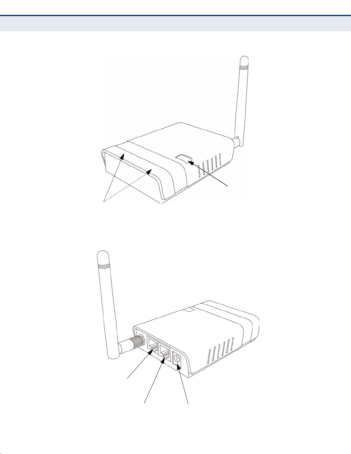
Figure 1: Top Panel
CHAPTER 1 | Introduction
Hardware Description
LED Indicators
Figure 2: Rear Pan
WPS Button
RJ-45 WAN Port
RJ-45 LAN Port
DC Power
So
– 21 –
cket
Page 17

CHAPTER 1 | Introduction
Hardware Description
LED INDICATORS The Mini Broadband Router includes four status LED indicators, as
described in the following figure and table.
Figure 3: LEDs
WLAN
Power
LAN
WAN
Table 2: LED Behavior
LED Status Description
Power On Blue The unit is receiving power and is operating
Off There is no power currently being supplied to
WLAN
WAN
LAN On Blue The Ethernet LAN port is connected to a PC or
On/Blinking Blue The 802.11n radio is enabled and
Off
On Blue
Blinking The Ethernet WAN port is connected and is
Off The Ethernet WAN port is disconnected or has
Blinking The Ethernet port is connected and is
Off The Ethernet port is disconnected or has
normally.
the unit.
transmitting or receiving data through wireless
links.
The 802.11n radio is disabled.
The Ethernet WAN port is aquiring an IP
address.
transmitting/receiving data.
malfunctioned.
server.
transmitting/receiving data.
malfunctioned.
– 22 –
Page 18

CHAPTER 1 | Introduction
Hardware Description
ETHERNET WAN PORT
ETHERNET LAN PORT
POWER CONNECTOR
WPS BUTTON
A 100BASE-TX RJ-45 port that can be attached to an Internet access
device, such as a DSL or Cable modem.
The Mini Broadband Router has one 100BASE-TX RJ-45 port that can be
attached directly to a PC or 10BASE-T/100BASE-TX LAN segments.
This port supports automatic MDI/MDI-X operation, so you can use
straight-through cables for all network connections to PCs, switches, or
hubs.
The Mini Broadband Router must be powered with its supplied power
adapter. Failure to do so results in voiding of any warrantly supplied with
the product. The power adapter automatically adjusts to any voltage
between 100~240 volts at 50 or 60 Hz, and supplies 12 volts DC power to
the unit. No voltage range settings are required.
Press the WPS button to automatically configure the Mini Broadband
Router with other WPS devices in the WLAN.
RESET BUTTON
The Reset button is used to restore the factory default configuration. If you
hold down the button for 5 seconds or more, any configuration changes
you may have made are removed, and the factory default configuration is
restored to the Mini Broadband Router.
Figure 4: Bottom Panel
Reset Button
– 23 –
Page 19

2 NETWORK PLANNING
Mini Router
Server
(IP: 192.168.2.x)
Desktop PC
(IP: 192.168.2.x)
Cable/DSL
Modem
Internet
Service
Provider
Notebook PC
(IP: 192.168.2.x)
WAN (IP assigned from ISP)
LAN (IP: 192.168.2.x)
LAN Switch
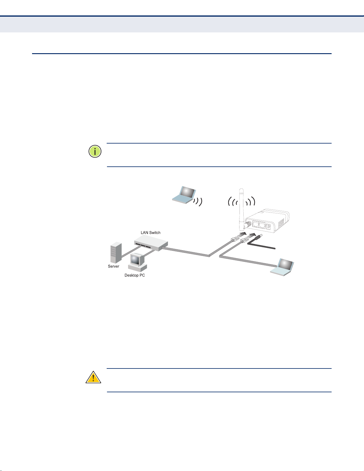
The Mini Broadband Router is designed to be very flexible in its deployment
options. It can be used as an Internet gateway for a small network, or as
an access point to extend an existing wired network to support wireless
users. It also supports use as a wireless bridge to connect up to an wired
LANs, or as a wireless client to connect to another wireless network
This chapter explains some of the basic features of the Mini Broadband
Router and shows some network topology examples in which the device is
implemented.
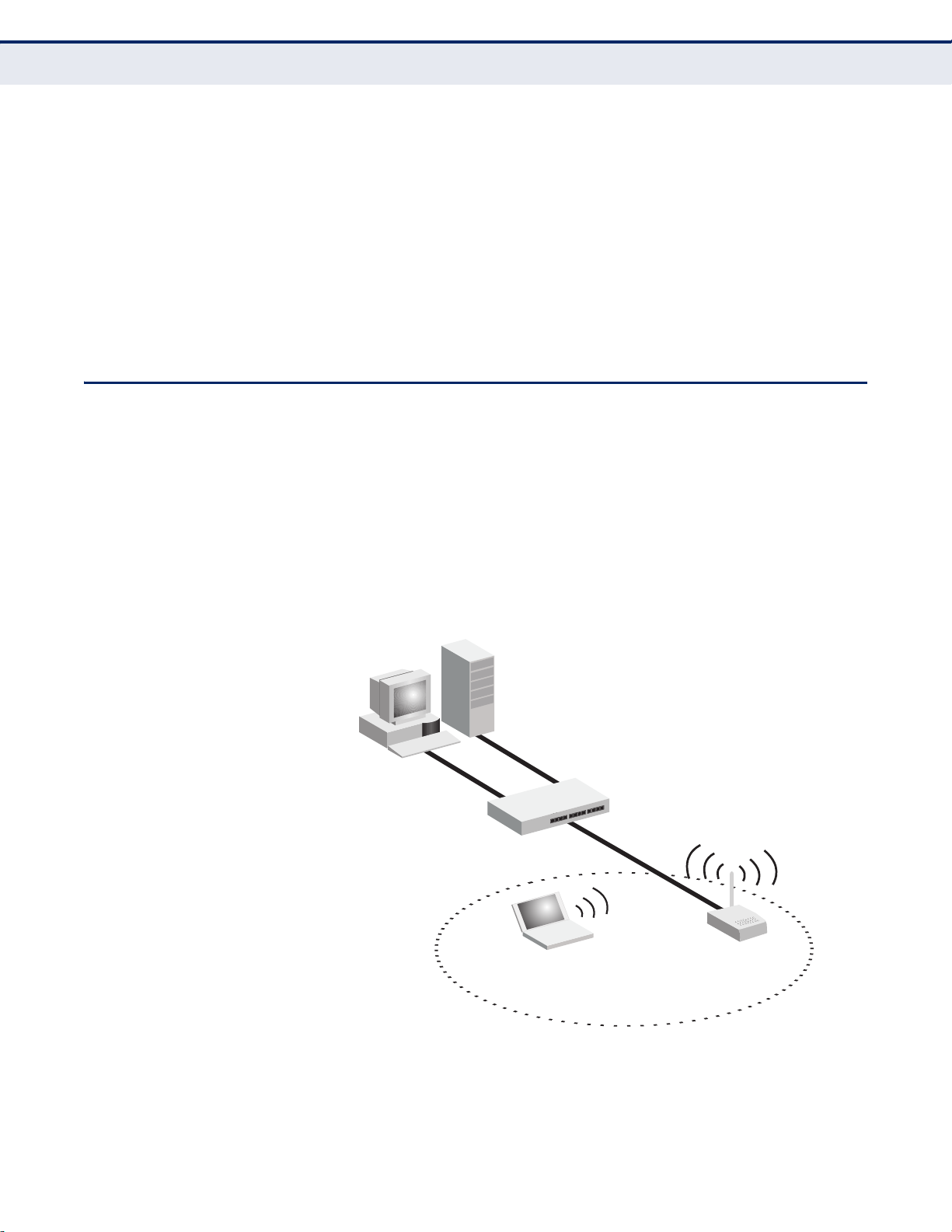
INTERNET GATEWAY ROUTER
The Mini Broadband Router can connect directly to a cable or DSL modem
to provide an Internet connection for multiple users through a single
service provider account. Users connect to the Mini Broadband Router
either through a wired connection to a LAN port, or though the device’s
own wireless network. The Mini Broadband Router functions as an Internet
gateway when set to Router Mode.
An Internet gateway employs several functions that essentially create two
separate Internet Protocol (IP) subnetworks; a private internal network
with wired and wireless users, and a public external network that connects
to the Internet. Network traffic is forwarded, or routed, between the two
subnetworks.
Figure 5: Operating as an Internet Gateway Router
– 24 –
Page 20
LAN ACCESS POINT
Server
(IP: 192.168.2.x)
Desktop PC
(IP: 192.168.2.x)
LAN Switch
Notebook PC
(IP: 192.168.2.x)
Mini Router
C
HAPTER
2
| Network Planning
LAN Access Point
The private local network, connected to the LAN port or wireless interface,
provides a Dynamic Host Configuration Protocol (DHCP) server for
allocating IP addresses to local PCs and wireless clients, and Network
Address Translation (NAT) for mapping the multiple "internal" IP addresses
to one “external” IP address.
The public external network, connected to the WAN port, supports DHCP
client, Point-to-Point Protocol over Ethernet (PPPoE), PPTP (Point-to-Point
Tunneling Protocol), L2TP (Layer 2 Tunneling Protocol), and static IP for
connection to an Internet service provider (ISP) through a cable or DSL
modem.
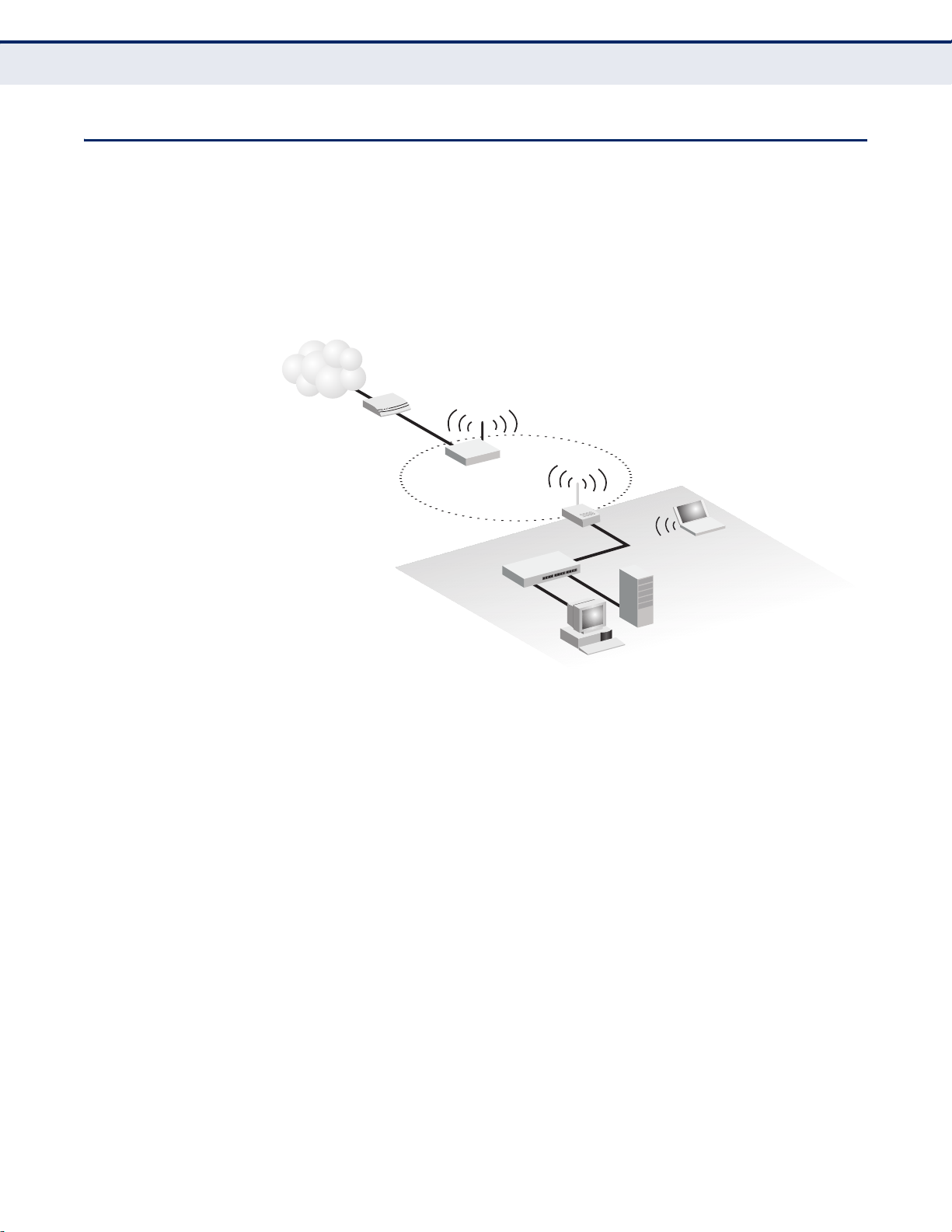
The Mini Broadband Router can provide an access point service for an
existing wired LAN, creating a wireless extension to the local network. The
Mini Broadband Router functions as purely an access point when set to
Bridge Mode. When used in this mode, there are no gateway functions
between the WAN port and the LAN and wireless interface.
A Wi-Fi wireless network is defined by its Service Set Identifier (SSID) or
network name. Wireless clients that want to connect to a network must set
their SSID to the same SSID of the network service.
Figure 6: Operating as an Access Point
– 25 –
Page 21
WIRELESS BRIDGE
Desktop PC
Cable/DSL
Modem
Mini Router
(Bridge Mode)
WDS Link
Internet
Service
Provider
Mini Router
(Router Mode)
Desktop PC
Cable/DSL
Modem
Mini Router
(Bridge Mode)
WDS Link
Internet
Service
Provider
Notebook PC
Mini Router
(Router Mode)
Notebook PC
C
HAPTER
2
| Network Planning
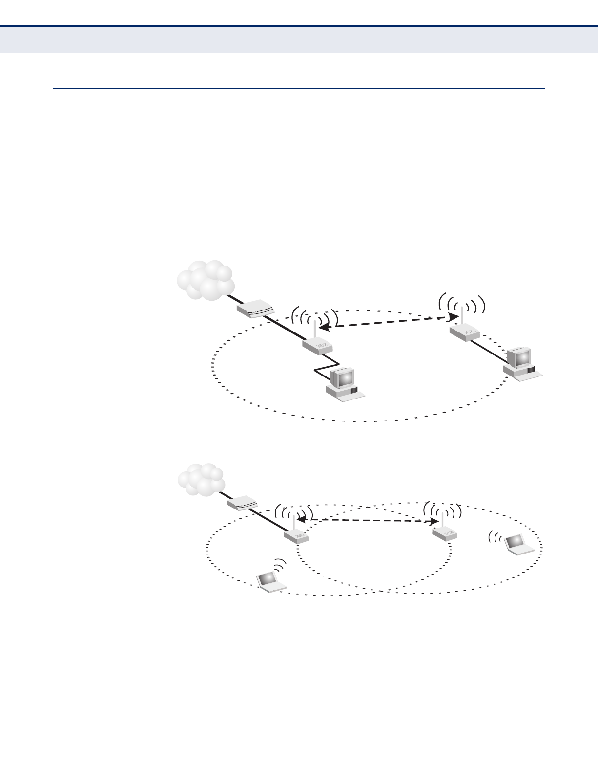
Wireless Bridge
The IEEE 802.11 standard defines a Wireless Distribution System (WDS)
for bridge connections between access points. The Mini Broadband Router
can use WDS to forward traffic on links between units.
Up to four WDS links can be specified for the Mini Broadband Router.
The WDS feature enables two basic functions to be configured in the
wireless network. Either a repeater function that extends the range of the
wireless network, or a bridge function that connects a remote LAN segment
to an Internet connection.
Figure 7: Operating as a Wireless Bridge
Figure 8: Operating as a Wireless Repeater
– 26 –
Page 22
WIRELESS CLIENT
Cable/DSL
Modem
Internet
Service
Provider
Server
(IP: 192.168.2.x)
Desktop PC
(IP: 192.168.2.x)
Notebook PC
(IP: 192.168.2.x)
Wireless Client WAN
(IP from external network)
LAN Port
(IP: 192.168.2.x)
LAN Switch
Access Point
(External SSID)
Mini Router
C
HAPTER
2
| Network Planning
Wireless Client
The Mini Broadband Router can operate as a wireless client on one SSID
interface, which enables a connection to another Wi-Fi network. When the
wireless client option is enabled, the client SSID interface functions as an
external gateway WAN port. When the wireless client option is enabled as a
LAN connection, the other SSID interface and LAN ports all function as the
local network within the same IP subnet.
Figure 9: Operating as a Wireless Client
– 27 –
Page 23

3 INSTALLING THE MINI ROUTER
The Mini Broadband Router has two basic operating modes that can be set
through the web-based management interface. For information on setting
the mode suitable for your network environment. See “Operation Mode” on
page 49.
◆ Router Mode — A gateway mode that connects a wired LAN and
wireless clients to an Internet access device, such as a cable or DSL
modem. This is the factory set default mode.
◆ Bridge Mode — An access point mode that extends a wired LAN to
wireless clients.
In addition to these basic operating modes, the wireless interface supports
Wireless Distribution System (WDS) links to other Mini Broadband Routers,
and a wireless AP Client Mode for a link to another wireless network. These
advanced configurations are not described in this section. See “Network
Planning” on page 24 for more information.
In a basic configuration, how the Mini Broadband Router is connected
depends on the operating mode. The sections in this chapter describe
connections for basic Router Mode and Bridge Mode operation.
SYSTEM REQUIREMENTS
You must meet the following minimum requirements:
◆ An Internet access device (DSL or Cable modem) with an Ethernet port
◆ An up-to-date web browser: Internet Explorer 6.0 or above or Mozilla
connection.
Firefox 2.0 or above.
– 28 –
Page 24

MOUNTING THE DEVICE
The Mini Broadband Router can be mounted on any horizontal surface, or
on a wall. The following sections describe the mounting options.
CHAPTER 1 | Installing the Mini Router
Mounting the Device
MOUNTING ON A WALL
The Mini Broadband Router should be mounted only to a wall or wood
surface that is at least 1/2-inch plywood or its equivalent. To mount the
unit on a wall, always use its wall-mounting slots.
Figure 10: Wall Mounting
Mounting Slots
To mount on a wall, follow the instructions below.
1. Mark the position of the two screw holes on the wall. For concrete or
brick walls, you will need to drill holes and insert wall plugs for the
screws.
MOUNTING ON A
HORIZONTAL SURFACE
2. Insert two 20-mm M4 tap screws (not included) into the holes, leaving
about 2~3 mm (0.08~0.12 inches) clearance from the wall.
3. Line up the two mounting points on the unit with the screws in the wall,
then slide the unit down onto the screws until it is in a secured position.
To keep the Mini Broadband Router from sliding on the surface, the unit has
four rubber feet on its base.
It is recommended to select an uncluttered area on a sturdy surface, such
as a desktop or table. The unit can also be protected by securing all
attached cables to a table leg or other nearby fixed structure.
– 29 –
Page 25

4.
Set up w ir el ess
devi ce s
Note bo ok P C
3.
Conn ec t AC po wer
adap te r to p ower so ur ce
Cabl e/ DS L Mo de m
1.
Conn ec t WAN po rt t o
cabl e/ DS L mo de m
Inte rn et
ROUTER MODE CONNECTIONS
In its default Router Mode, the Mini Broadband Router forwards traffic
between an Internet connected cable or DSL modem, and wired or wireless
PCs or notebooks. The basic connections are illustrated in the figure below.
Figure 11: Router Mode Connection
CHAPTER 3 |
Installing the Mini Router
Router Mode Connections
Conn ec t LA N port
2.
to PC
To connect the Mini Broadband Router in Router Mode for use as an
Internet gateway, follow these steps:
1. Connect an Ethernet cable from the Mini Broadband Router’s WAN port
to your Internet connected cable or DSL modem.
2. Connect an Ethernet cable from the Mini Broadband Router’s LAN port
to your PC. Alternatively, you can connect to a workgroup switch to
support more wired users. The Mini Broadband Router can support up
to 253 wired and wireless users.
3. Power on the Mini Broadband Router by connecting the AC power
adapter and plugging it into a power source.
:
CAUTION
Router. Otherwise, the product may be damaged.
Use ONLY the power adapter supplied with the Mini Broadband
When you power on the Mini Broadband Router, verify that the Power
LED turns on and that the other LED indicators start functioning as
described under see “LED Indicators” on page 22.
4. Set up wireless devices by pressing the WPS button on the Mini
Broadband Router or by using the web interface. See “Initial
Configuration” on page 33 for more information on accessing the web
interface.
– 30 –
Page 26
BRIDGE MODE CONNECTIONS
3.
Set up w ir el es s
devi ce s
Note bo ok P C
2.
Conn ec t AC po we r
adap te r to p ow er s ource
1.
Conn ec t LA N an d WAN po rt s
to PCs o r an E th er ne t LAN switc h
In Bridge Mode, the Mini Broadband Router operates as a wireless access
point, extending a local wired network to associated wireless clients (PCs
or notebooks with wireless capability). From any nearby location, you can
then make a wireless connection to the Mini Broadband Router and access
the wired network resources, including local servers and the Internet.
In Bridge Mode, the Mini Broadband Router does not support gateway
functions on its WAN port. Both the LAN port and the WAN ports can be
connected to a local Ethernet LAN.
N
OTE
:
Bridge Mode is not the factory default mode and must be manually
set using the web management interface.
Figure 12: Bridge Mode Connection
C
HAPTER
3
| Installing the Mini Router
Bridge Mode Connections
To connect the Mini Broadband Router for use as an access point, follow
these steps:
1. Using Ethernet cable connect the Mini Broadband Router’s LAN and
WAN ports to PCs. Alternatively, you can connect to a workgroup switch
to support more wired users.
2. Power on the Mini Broadband Router by connecting the AC power
adapter and plugging it into a power source.
C
AUTION
Router. Otherwise, the product may be damaged.
:
Use ONLY the power adapter supplied with the Mini Broadband
When you power on the Mini Broadband Router, verify that the Power
LED turns on and that the other LED indicators start functioning as
described under “LED Indicators” on page 22.
– 31 –
Page 27

C
HAPTER
3
| Installing the Mini Router
Bridge Mode Connections
3. Set up wireless devices by pressing the WPS button on the Mini
Broadband Router or by using the web interface. See “Initial
Configuration” on page 33 for more information on accessing the web
interface.
– 32 –
Page 28

4 INITIAL CONFIGURATION
The Mini Broadband Router offers a user-friendly web-based management
interface for the configuration of all the unit’s features. Any PC directly
attached to the unit can access the management interface using a web
browser, such as Internet Explorer (version 6.0 or above).
ISP SETTINGS
If you are not sure of your connection method, please contact your
Internet Service Provider. There are several connection types to choose
from: Static IP, DHCP (cable connection), PPPoE (DSL connection), PPTP,
and L2TP.
N
OTE
:
If using the PPPoE option, you will need to remove or disable any
PPPoE client software on your computers.
CONNECTING TO THE LOGIN PAGE
It is recommended to make initial configuration changes by connecting a
PC directly to the Mini Broadband Router’s LAN port. The Mini Broadband
Router has a default IP address of 192.168.2.1 and a subnet mask of
255.255.255.0. You must set your PC IP address to be on the same subnet
as the Mini Broadband Router (that is, the PC and Mini Broadband Router
addresses must both start 192.168.2.x).
To access the Mini Broadband Router’s management interface, follow these
steps:
1. Use your web browser to connect to the management interface using
the default IP address of 192.168.2.1.
2. Log into the interface by entering the default username “admin” and
password “
N
OTE
:
It is strongly recommended to change the default user name and
password the first time you access the web interface. For information on
changing user names and passwords, See “System Management” on
page 97.
admin,” then click OK.
– 33 –
Page 29
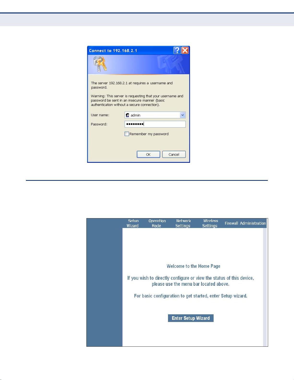
Figure 13: Login Page
CHAPTER 4 |
Home Page and Main Menu
Initial Configuration
HOME PAGE AND MAIN MENU
After logging in to the web interface, the Home page displays. The Home
page shows the main menu and the method to access the Setup Wizard.
Figure 14: Home Page
– 34 –
Page 30

COMMON WEB PAGE BUTTONS
The list below describes the common buttons found on most web
management pages:
◆ Apply – Applies the new parameters and saves them to memory. Also
displays a screen to inform you when it has taken affect. Clicking
‘Apply’ returns to the home page.
◆ Cancel – Cancels the newly entered settings and restores the previous
settings.
◆ Next – Proceeds to the next step.
◆ Previous – Returns to the previous screen.
SETUP WIZARD
C
HAPTER
4
| Initial Configuration
Common Web Page Buttons
STEP 1 - LANGUAGE
SELECTION
The Wizard is designed to help you configure the basic settings required to
get the the Mini Broadband Router up and running. There are only a few
basic steps you need to set up the the Mini Broadband Router and provide
a connection.
Follow these steps:
Select between English, Traditional Chinese, Simple Chinese, or Korean.
Click Next to proceed to the next step of the wizard.
Figure 15: Wizard Step 1 - Language Selection
The following items are displayed on the first page of the Setup Wizard:
◆ Select Language — Selects English, Traditional Chinese, Simple
Chinese, or Korean as the interface language.
– 35 –
Page 31

C
HAPTER
4
| Initial Configuration
Setup Wizard
STEP 2 - TIME
SETTINGS
The Step 2 page of the Wizard configures time zone and SNTP settings.
Select a time zone according to where the device is operated. Click Next
after completing the setup.
Figure 16: Wizard Step 2 - Time and SNTP Settings
The following items are displayed on this page:
◆ Current Time — Receives a time and date stamp from an SNTP server.
◆ Time Zone — Select the time zone that is applicable to your region.
◆ SNTP Server — Enter the address of an SNTP server to receive time
updates.
◆ SNTP synchronization (hours) — Specify the interval between SNTP
server updates.
– 36 –
Page 32
CHAPTER4 |
Initial Configuration
Setup Wizard
STEP 3 - WAN
ETTINGS - DHCP
S
The Step 3 page of the Wizard specifies the Internet connection
parameters for the Mini Broadband Router’s WAN port. Click Next after
completing the setup.
By default, the access point WAN port is configured with DHCP enabled.
The options are Static IP, DHCP (cable modem), PPPoE (DSL modem),
PPTP, and L2TP. Each option changes the parameters that are displayed on
the page.
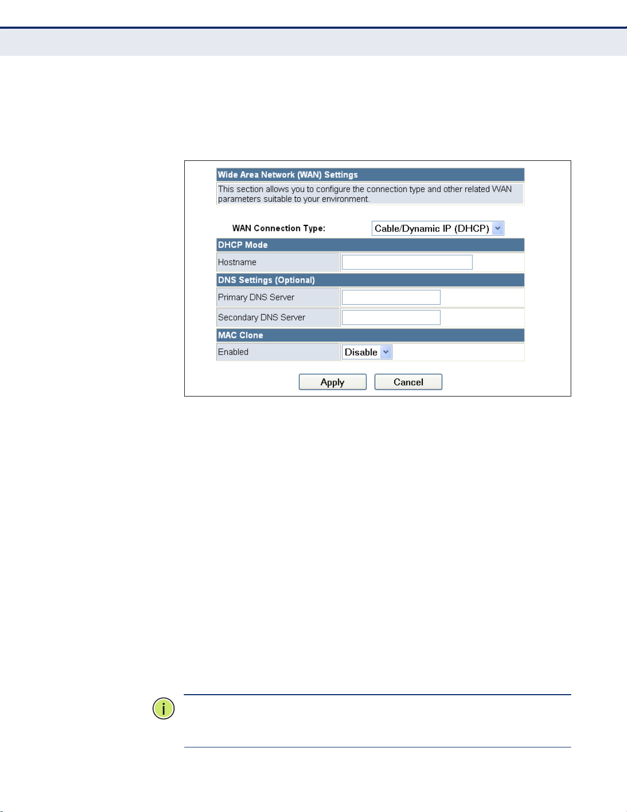
Figure 17: Wizard Step 3 - WAN Settings - DHCP
The following items are displayed on this page:
WAN Connec t i o n Type — Select the connection type for the WAN port
from the drop down list. (Default: DHCP)
Hostname — Specifies the host name of the DHCP client.
Primary DN S S e rver — The IP address of the Primary Domain Name
Server. A DNS maps numerical IP addresses to domain names and can
be used to identify network hosts by familiar names instead of the IP
addresses. To specify a DNS server, type the IP addresses in the text
field provided. Otherwise, leave the text field blank.
Secondary D N S Server — The IP address of the Secondary Domain
Name Server.
MAC Clone — Some ISPs limit Internet connections to a specified MAC
address of one PC, which is registered with the ISP. This setting allows
you to manually change the MAC address of the Mini Broadband
Router's WAN interface to match the PC's MAC address provided to your
ISP for registration. You can enter the registered MAC address manually
by typing it in the boxes provided. Otherwise, connect only the PC with
the registered MAC address to the Mini Broadband Router, then click the
“Clone your PC’s MAC Address”. (Default: Disabled)
– 37 –
Page 33

C
HAPTER
N
OTE
:
If you are unsure of the PC MAC address originally registered by
4
| Initial Configuration
Setup Wizard
your ISP, call your ISP and request to register a new MAC address for your
account. Register the default MAC address of the Mini Broadband Router.
STEP 3 - WAN
SETTINGS - STATIC IP
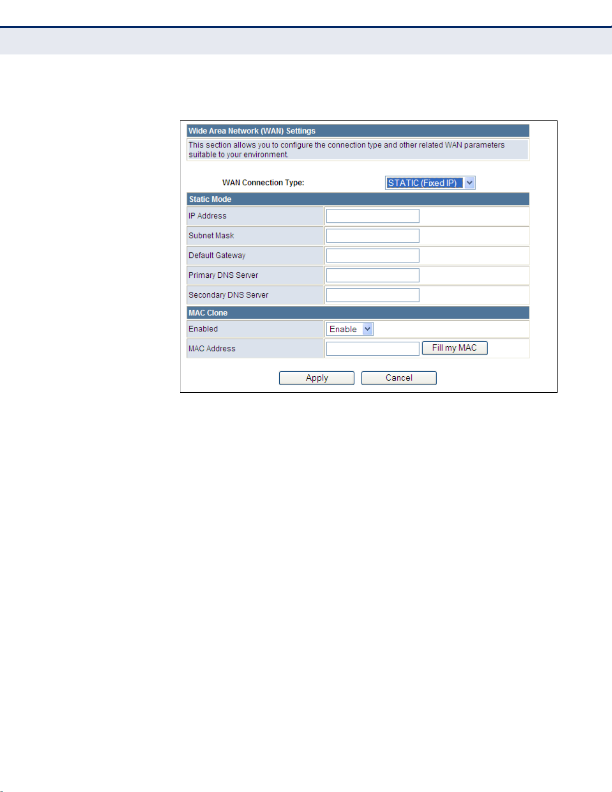
Configures a static IP for the WAN port.
Figure 18: Wizard Step 3 - WAN Settings - Static IP
The following items are displayed on this page:
◆ WAN Connection Type — Select the connection type for the WAN port
from the drop down list. (Default: DHCP)
◆ IP Address — The IP address of the Mini Broadband Router. Valid IP
addresses consist of four decimal numbers, 0 to 255, separated by
periods.
◆ Subnet Mask — The mask that identifies the host address bits used for
routing to specific subnets.
◆ Default Gateway — The IP address of the gateway router for the Mini
Broadband Router, which is used if the requested destination address is
not on the local subnet.
◆ Primary DNS Server — The IP address of the Primary Domain Name
Server. A DNS maps numerical IP addresses to domain names and can
be used to identify network hosts by familiar names instead of the IP
addresses. To specify a DNS server, type the IP addresses in the text
field provided. Otherwise, leave the text field blank.
◆ Secondary DNS Server — The IP address of the Secondary Domain
Name Server.
– 38 –
Page 34

C
HAPTER
4
| Initial Configuration
Setup Wizard
◆ MAC Clone — Some ISPs limit Internet connections to a specified MAC
address. This setting allows you to manually change the MAC address
of the Mini Broadband Router's WAN interface to match the PC's MAC
address provided to your ISP for registration. You can enter the
registered MAC address manually by typing it in the boxes provided.
Otherwise, connect only the PC with the registered MAC address to the
Mini Broadband Router, then click the “Clone your PC’s MAC Address”
(Default: Disable)
STEP 3 - WAN
SETTINGS - PPPOE
Enable the Mini Broadband Router IP address to be assigned automatically
from an Internet service provider (ISP) through a DSL modem using Pointto-Point Protocol over Ethernet (PPPoE).
Figure 19: Wizard Step 3 - WAN Settings - PPPoE
The following items are displayed on this page:
◆ User Name — Sets the PPPoE user name for the WAN port.
(Default: pppoe_user; Range: 1~32 characters)
◆ Password — Sets a PPPoE password for the WAN port.
(Default: pppoe_password; Range: 1~32 characters)
◆ Verify Password — Prompts you to re-enter your chosen password.
◆ Operation Mode — Enables and configures the keep alive time and
configures the on-demand idle time.
◆ MAC Clone — Some ISPs limit Internet connections to a specified MAC
address of one PC. This setting allows you to manually change the MAC
address of the Mini Broadband Router's WAN interface to match the
PC's MAC address provided to your ISP for registration. You can enter
the registered MAC address manually by typing it in the boxes
– 39 –
Page 35

C
HAPTER
4
| Initial Configuration
Setup Wizard
provided. Otherwise, connect only the PC with the registered MAC
address to the Mini Broadband Router, then click the “Clone your PC’s
MAC Address” (Default: Disable)
STEP 3 - WAN
SETTINGS - PPTP
Enables the Point-to-Point Tunneling Protocol (PPTP) for implementing
virtual private networks. The service is provided in many European
countries.
Figure 20: Wizard Step 3 - WAN Settings - PPTP
The following items are displayed on this page:
◆ Server IP — Sets the PPTP server IP Address. (Default: pptp_server)
◆ User Name — Sets the PPTP user name for the WAN port.
(Default: pptp_user; Range: 1~32 characters)
◆ Password — Sets a PPTP password for the WAN port. (Default:
pptp_password; Range: 1~32 characters)
◆ Verify Password — Prompts you to re-enter your chosen password.
◆ Address Mode — Sets a PPTP network mode. (Default: Static)
– 40 –
Page 36

C
HAPTER
4
| Initial Configuration
Setup Wizard
◆ IP Address — Sets the static IP address. (Default: 0.0.0.0, available
when PPTP Network Mode is set to static IP.)
◆ Subnet Mask — Sets the static IP subnet mask. (Default:
255.255.255.0, available when PPTP Network Mode is set to static IP.)
◆ Default Gateway — The IP address of a router that is used when the
requested destination IP address is not on the local subnet.
◆ Operation Mode — Enables and configures the keep alive time.
◆ Primary DNS Server — The IP address of the Primary Domain Name
Server. A DNS maps numerical IP addresses to domain names and can
be used to identify network hosts by familiar names instead of the IP
addresses. To specify a DNS server, type the IP addresses in the text
field provided. Otherwise, leave the text field blank.
◆ Secondary DNS Server — The IP address of the Secondary Domain
Name Server.
◆ MAC Clone — Some ISPs limit Internet connections to a specified MAC
address of one PC. This setting allows you to manually change the MAC
address of the Mini Broadband Router's WAN interface to match the
PC's MAC address provided to your ISP for registration. You can enter
the registered MAC address manually by typing it in the boxes
provided. Otherwise, connect only the PC with the registered MAC
address to the Mini Broadband Router, then click the “Clone your PC’s
MAC Address” (Default: Disable)
– 41 –
Page 37

C
HAPTER
4
| Initial Configuration
Setup Wizard
STEP 3 - WAN
SETTINGS - L2TP
Enables the Layer 2 Tunneling Protocol (L2TP) for implementing virtual
private networks. The service is provided in many European countries.
Figure 21: Wizard Step 3 - WAN Settings - L2TP
The following items are displayed on this page:
◆ Server IP — Sets the L2TP server IP Address. (Default: l2tp_server)
◆ User Name — Sets the L2TP user name for the WAN port.
(Default: l2tp_user; Range: 1~32 characters)
◆ Password — Sets a L2TP password for the WAN port. (Default:
l2tp_password; Range: 1~32 characters)
◆ Verify Password — Prompts you to re-enter your chosen password.
◆ Address Mode — Sets a L2TP network mode. (Default: Static)
◆ IP Address — Sets the static IP address. (Default: 0.0.0.0, available
when L2TP Network Mode is set to static IP.)
◆ Subnet Mask — Sets the static IP subnet mask. (Default:
255.255.255.0, available when L2TP Network Mode is set to static IP.)
– 42 –
Page 38

CHAPTER4 |
Default Gateway — The IP address of a router that is used when the
requested destination IP address is not on the local subnet.
Operation Mod e — Enables and configures the keep alive time.
Primary DNS Serv e r — The IP address of the Primary Domain Name
Server. A DNS maps numerical IP addresses to domain names and can
be used to identify network hosts by familiar names instead of the IP
addresses. To specify a DNS server, type the IP addresses in the text
field provided. Otherwise, leave the text field blank.
Secondary DNS S e r v e r — The IP address of the Secondary Domain
Name Server.
MAC Clone — Some ISPs limit Internet connections to a specified MAC
address of one PC. This setting allows you to manually change the MAC
address of the Mini Broadband Router’s WAN interface to match the
PC's MAC address provided to your ISP for registration. You can enter
the registered MAC address manually by typing it in the boxes
provided. Otherwise, connect only the PC with the registered MAC
address to the Mini Broadband Router, then click the “Clone your PC’s
MAC Address” (Default: Disable)
Initial Configuration
Setup Wizard
STEP 4 - WRELESS
SECURITY
The Step 4 page of the Wizard configures the wireless network name and
security options.
Figure 22: Wizard Step 4 - Wireless Security
The following items are displayed on this page:
SSID Choice — The name of the wireless network service provided by
the Mini Broadband Router. Clients that want to connect to the network
must set their SSID to the same as that of the Mini Broadband Router.
(Default: “”)
– 43 –
Page 39

C
HAPTER
4
| Initial Configuration
Setup Wizard
◆ Security Mode — Specifies the security mode for the SSID. Select the
security method and then configure the required parameters. For more
information, see “WLAN Security” on page 74. (Options: Disabled,
Open, Shared, WEP-AUTO, WPA-PSK, WPA2-PSK, WPA-PSK_WPA2-PSK,
WPA, WPA2, WPA1_WPA2, 802.1X; Default: Disabled)
N
OTE
:
To keep your wireless network protected and secure, you should
implement the highest security possible. For small networks, it is
recommended to select WPA2-PSK using AES encryption as the most
secure option. However, if you have older wireless devices in the network
that do not support AES encryption, select TKIP as the encryption
algorithm.
◆ Access Policy — The Mini Broadband Router provides a MAC address
filtering facility. The access policy can be set to allow or reject specific
station MAC addresses. This feature can be used to connect known
wireless devices that may not be able to support the configured
security mode.
◆ Add a station MAC — Enter the MAC address of the station that you
want to filter. MAC addresses must be entered in the format
xx:xx:xx:xx:xx:xx.
COMPLETION After completion of the Wizard, the screen returns to the Home Page.
– 44 –
Page 40

S
ECTION
WEB CONFIGURATION
This section provides details on configuring the Mini Broadband Router
using the web browser interface.
This section includes these chapters:
◆ “Operation Mode” on page 46
◆ “Network Settings” on page 50
◆ “Wireless Configuration” on page 64
◆ “Firewall Configuration” on page 88
II
◆ “Administration Settings” on page 96
– 45 –
Page 41

5 OPERATION MODE
The Mini Broadband Router offers a user-friendly web-based management
interface for the configuration of all the unit’s features. Any PC directly
attached to the unit can access the management interface using a web
browser, such as Internet Explorer (version 6.0 or above).
The following sections are contained in this chapter:
◆ “Logging In” on page 47
◆ “Operation Mode” on page 49
– 46 –
Page 42

LOGGING IN
C
HAPTER
5
| Operation Mode
Logging In
It is recommended to make initial configuration changes by connecting a
PC directly to the Mini Broadband Router's LAN port. The Mini Broadband
Router has a default IP address of 192.168.2.1 and a subnet mask of
255.255.255.0. If your PC is set to “Obtain an IP address automatically”
(that is, set as a DHCP client), you can connect immediately to the web
interface. Otherwise, you must set your PC IP address to be on the same
subnet as the Mini Broadband Router (that is, the PC and Mini Broadband
Router addresses must both start 192.168.2.x).
To access the configuration menu, follow these steps:
1. Use your web browser to connect to the management interface using
the default IP address of 192.168.2.1.
2. Log into the Mini Broadband Router management interface by entering
the default user name “admin” and password “
OK.
admin,” then click
N
OTE
:
It is strongly recommended to change the default user name and
password the first time you access the web interface. For information on
changing user names and passwords, see “Administration Settings” on
page 96.
Figure 23: Logging On
– 47 –
Page 43

C
HAPTER
5
| Operation Mode
Logging In
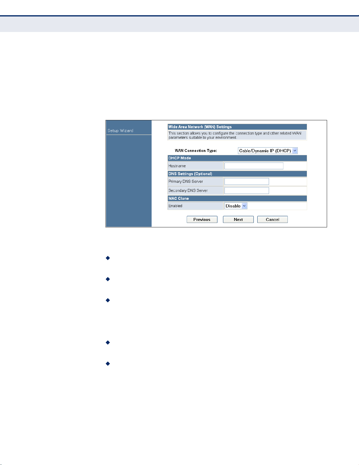
The home page displays the main menu items at the top of the screen and
the Setup Wizard. See “Setup Wizard” on page 35.
Figure 24: Home Page
N
OTE
:
The displayed pages and settings may differ depending on whether
the unit is in Router or Bridge Mode. See “Operation Mode” on page 49.
– 48 –
Page 44
OPERATION MODE
C
HAPTER
5
| Operation Mode
Operation Mode
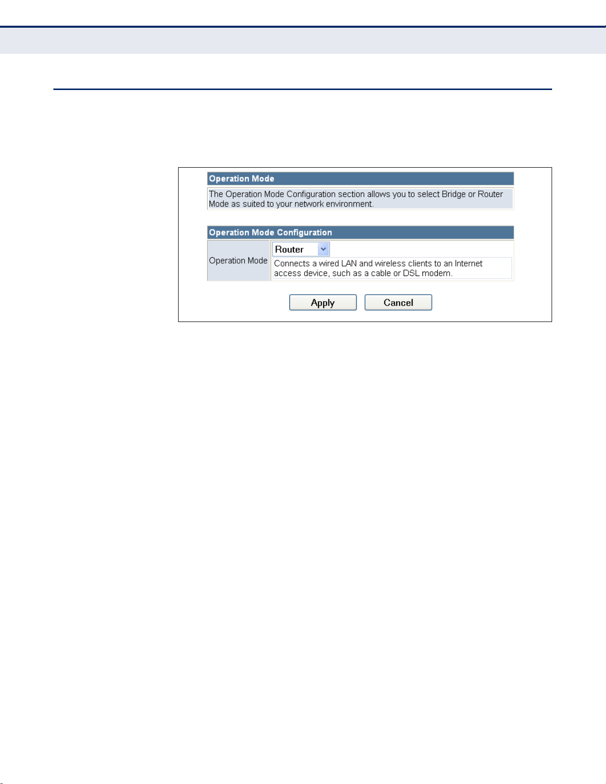
The Operation Mode Configuration page allows you to set up the mode
suitable for your network environment.
Figure 25: Operation Mode
The following items are displayed on this page:
◆ Bridge Mode — An access point mode that extends a wired LAN to
wireless clients.
◆ Router Mode — The Internet gateway mode that connects a wired LAN
and wireless clients to an Internet access device, such as a cable or
DSL modem. This is the factory set default mode.
◆ AP Client Mode — The wireless client mode that connects to another
wireless network. In this mode the wireless client SSID interface
operates as the WAN connection.
– 49 –
Page 45

6 NETWORK SETTINGS
The Network Settings pages allow you to manage basic system
configuration settings. It includes the following sections:
◆ “WAN Setting” on page 50
■
“DHCP” on page 51
■
“Static IP” on page 52
■
“PPPoE” on page 53
■
“PPTP” on page 54
■
“L2TP” on page 56
◆ “LAN Setting” on page 58
WAN SETTING
◆ “DHCP Clients” on page 60
◆ “Advanced Routing” on page 61
N
OTE
:
In Bridge mode, the Mini Broadband Router’s Network Settings
options are significantly reduced, with only LAN Settings and the Client List
being available to the user.
The WAN Setting page specifies the Internet connection parameters. Click
on “Network Settings” followed by “WAN”.
◆ WAN Connection Type — By default, the access point WAN port is
configured with DHCP enabled. After you have network access to the
access point, you can use the web browser interface to modify the
initial IP configuration, if needed. The options are Static IP, DHCP (cable
modem), PPPoE (DSL modem), PPTP, and L2TP. Each option changes
the parameters displayed below it. (Default: DHCP).
– 50 –
Page 46
C
HAPTER
6
| Network Settings
WAN Setting
DHCP Enables Dynamic Host Configuration Protocol (DHCP) for the WAN port.
This setting allows the Mini Broadband Router to automatically obtain an IP
address from a DHCP server normally operated by the Internet Service
Provider (ISP).
Figure 26: DHCP Configuration
The following items are displayed on this page:
◆ Hostname (Optional) — The hostname of the DHCP client.
◆ Primary DNS Server — The IP address of the Primary Domain Name
Server. A DNS maps numerical IP addresses to domain names and can
be used to identify network hosts by familiar names instead of the IP
addresses. To specify a DNS server, type the IP addresses in the text
field provided. Otherwise, leave the text field blank.
◆ Secondary DNS Server — The IP address of the Secondary Domain
Name Server.
◆ MAC Clone — Some ISPs limit Internet connections to a specified MAC
address of one PC. This setting allows you to manually change the MAC
address of the Mini Broadband Router's WAN interface to match the
PC's MAC address provided to your ISP for registration. You can enter
the registered MAC address manually by typing it in the boxes
provided. Otherwise, connect only the PC with the registered MAC
address to the Mini Broadband Router, then click the “Clone your PC’s
MAC Address” (Default: Disable)
N
OTE
:
If you are unsure of the PC MAC address originally registered by
your ISP, call your ISP and request to register a new MAC address for your
account. Register the default MAC address of the Mini Broadband Router.
– 51 –
Page 47
STATIC IP Configures a static IP for the WAN port.
Figure 27: Static IP Configuration
C
HAPTER
6
| Network Settings
WAN Setting
The following items are displayed on this page:
◆ IP Address — The IP address of the Mini Broadband Router. Valid IP
addresses consist of four decimal numbers, 0 to 255, separated by
periods.
◆ Subnet Mask — The mask that identifies the host address bits used for
routing to specific subnets.
◆ Default Gateway — The IP address of the gateway router for the Mini
Broadband Router, which is used if the requested destination address is
not on the local subnet.
◆ Primary DNS Server — The IP address of the Primary Domain Name
Server on the network. A DNS maps numerical IP addresses to domain
names and can be used to identify network hosts by familiar names
instead of the IP addresses. If you have one or more DNS servers
located on the local network, type the IP addresses in the text fields
provided. Otherwise, leave the addresses as all zeros (0.0.0.0).
◆ Secondary DNS Server — The IP address of the Secondary Domain
Name Server on the network.
◆ MAC Clone — Some ISPs limit Internet connections to a specified MAC
address of one PC. This setting allows you to manually change the MAC
address of the Mini Broadband Router's WAN interface to match the
– 52 –
Page 48

C
HAPTER
6
| Network Settings
WAN Setting
PC's MAC address provided to your ISP for registration. You can enter
the registered MAC address manually by typing it in the boxes
provided. Otherwise, connect only the PC with the registered MAC
address to the Mini Broadband Router, then click the “Clone your PC’s
MAC Address” (Default: Disable)
PPPOE Enables the Mini Broadband Router IP address to be assigned automatically
from an Internet service provider (ISP) through a DSL modem using Pointto-Point Protocol over Ethernet (PPPoE).
Figure 28: PPPoE Configuration
The following items are displayed on this page:
◆ PPPoE User Name — Sets the PPPoE user name for the WAN port.
(Default: pppoe_user; Range: 1~32 characters)
◆ PPPoE Password — Sets a PPPoE password for the WAN port.
(Default: pppoe_password; Range: 1~32 characters)
◆ Verify Password — Prompts you to re-enter your chosen password.
◆ Operation Mode — Selects the operation mode as Keep Alive, On
Demand or Manual. (Default: Keep Alive)
■
Keep Alive Mode: The Mini Broadband Router will periodically
check your Internet connection and automatically re-establish your
connection when disconnected. (Default: 60 seconds)
– 53 –
Page 49

C
HAPTER
■
On Demand Mode: The maximum length of inactive time the unit
6
| Network Settings
WAN Setting
will stay connected to the DSL service provider before
disconnecting. (Default: 5 minutes)
◆ MAC Clone — Some ISPs limit Internet connections to a specified MAC
address of one PC. This setting allows you to manually change the MAC
address of the Mini Broadband Router's WAN interface to match the
PC's MAC address provided to your ISP for registration. You can enter
the registered MAC address manually by typing it in the boxes
provided. Otherwise, connect only the PC with the registered MAC
address to the Mini Broadband Router, then click the “Clone your PC’s
MAC Address” (Default: Disable)
PPTP Enables the Point-to-Point Tunneling Protocol (PPTP) for implementing
virtual private networks. The service is provided in many European
countries.
Figure 29: PPTP Configuration
– 54 –
Page 50

C
HAPTER
6
| Network Settings
WAN Setting
The following items are displayed on this page:
◆ Server IP — Sets a PPTP server IP Address. (Default: pptp_server)
◆ User Name — Sets the PPTP user name for the WAN port. (Default:
pptp_user; Range: 1~32 characters)
◆ Password — Sets a PPTP password for the WAN port. (Default:
pptp_password; Range: 1~32 characters)
◆ Verify Password — Prompts you to re-enter your chosen password.
◆ Address Mode — Sets a PPTP network mode. (Default: Static)
◆ IP Address — Sets the static IP address. (Default: 0.0.0.0, available
when PPTP Network Mode is set to static IP.)
◆ Subnet Mask — Sets the static IP subnet mask. (Default:
255.255.255.0, available when PPTP Network Mode is set to static IP.)
◆ Default Gateway — The IP address of the gateway router for the Mini
Broadband Router, which is used if the requested destination address is
not on the local subnet.
◆ Operation Mode — Selects the operation mode as Keep Alive, or
Manual. (Default: Keep Alive)
■
Keep Alive Mode: The Mini Broadband Router will periodically
check your Internet connection and automatically re-establish your
connection when disconnected. (Default: 60 seconds)
■
Manual Mode: The unit will remain connected to the Internet
without disconnecting.
◆ Primary DNS Server — The IP address of the Primary Domain Name
Server. A DNS maps numerical IP addresses to domain names and can
be used to identify network hosts by familiar names instead of the IP
addresses. To specify a DNS server, type the IP addresses in the text
field provided. Otherwise, leave the text field blank.
◆ Secondary DNS Server — The IP address of the Secondary Domain
Name Server.
◆ MAC Clone — Some ISPs limit Internet connections to a specified MAC
address of one PC. This setting allows you to manually change the MAC
address of the Mini Broadband Router's WAN interface to match the
PC's MAC address provided to your ISP for registration. You can enter
the registered MAC address manually by typing it in the boxes
provided. Otherwise, connect only the PC with the registered MAC
address to the Mini Broadband Router, then click the “Clone your PC’s
MAC Address” (Default: Disable)
– 55 –
Page 51

C
HAPTER
6
| Network Settings
WAN Setting
L2TP Enables the Layer 2 Tunneling Protocol (L2TP) for implementing virtual
private networks. The service is provided in many European countries.
Figure 30: L2TP Configuration
The following items are displayed on this page:
◆ Server IP — Sets the L2TP server IP Address. (Default: l2tp_server)
◆ User Name — Sets the L2TP user name for the WAN port.
(Default: l2tp_user; Range: 1~32 characters)
◆ Password — Sets a L2TP password for the WAN port. (Default:
l2tp_password; Range: 1~32 characters)
◆ Verify Password — Prompts you to re-enter your chosen password.
◆ Address Mode — Sets a L2TP network mode. (Default: Static)
– 56 –
Page 52

C
HAPTER
6
| Network Settings
WAN Setting
◆ IP Address — Sets the static IP address. (Default: 0.0.0.0, available
when L2TP Network Mode is set to static IP.)
◆ Subnet Mask — Sets the static IP subnet mask. (Default:
255.255.255.0, available when L2TP Network Mode is set to static IP.)
◆ Default Gateway — The IP address of the gateway router for the Mini
Broadband Router, which is used if the requested destination address is
not on the local subnet.
◆ Operation Mode — Selects the operation mode as Keep Alive, or
Manual. (Default: Keep Alive)
■
Keep Alive Mode: The Mini Broadband Router will periodically
check your Internet connection and automatically re-establish your
connection when disconnected. (Default: 60 seconds)
■
Manual Mode: The unit will remain connected to the Internet
without disconnecting.
◆ Primary DNS Server — The IP address of the Primary Domain Name
Server. A DNS maps numerical IP addresses to domain names and can
be used to identify network hosts by familiar names instead of the IP
addresses. To specify a DNS server, type the IP addresses in the text
field provided. Otherwise, leave the text field blank.
◆ Secondary DNS Server — The IP address of the Secondary Domain
Name Server.
◆ MAC Clone — Some ISPs limit Internet connections to a specified MAC
address of one PC. This setting allows you to manually change the MAC
address of the Mini Broadband Router's WAN interface to match the
PC's MAC address provided to your ISP for registration. You can enter
the registered MAC address manually by typing it in the boxes
provided. Otherwise, connect only the PC with the registered MAC
address to the Mini Broadband Router, then click the “Clone your PC’s
MAC Address” (Default: Disable)
– 57 –
Page 53

LAN SETTING
C
HAPTER
6
| Network Settings
LAN Setting
The Mini Broadband Router must have a valid IP address for management
using a web browser and to support other features. The unit has a default
IP address of 192.168.2.1. You can use this IP address or assign another
address that is compatible with your existing local network. Click on
“Network Settings” followed by “LAN.”
Figure 31: LAN Configuration
The following items are displayed on this page:
◆ MAC Address — The physical layer address for the Mini Broadband
Router’s LAN port.
◆ IP Address — Valid IP addresses consist of four decimal numbers, 0 to
255, separated by periods. (Default: 192.168.2.1)
– 58 –
Page 54

C
HAPTER
6
| Network Settings
LAN Setting
◆ Subnet Mask — Indicate the local subnet mask.
(Default: 255.255.255.0.)
◆ DHCP Server — Enable this feature to assign IP settings to wired and
wireless clients connected to the Mini Broadband Router. The IP
address, subnet mask, default gateway, and Domain Name Server
(DNS) address are dynamically assigned to clients. (Options: Enable,
Disable; Default: Enable)
◆ Start/End IP Address — Specify the start and end IP addresses of a
range that the DHCP server can allocate to DHCP clients. Note that the
address pool range is always in the same subnet as the unit’s IP
setting. The maximum clients that the unit can support is 253.
◆ Lease Time — Select a time limit for the use of an IP address from the
IP pool. When the time limit expires, the client has to request a new IP
address. The lease time is expressed in seconds. (Options: Forever, Two
weeks, One week, Two days, One day, Half day, Two hours, One hour,
Half hour; Default: One week)
◆ LLTD — Link Layer Topology Discovery (LLTD) is a Microsoft proprietary
discovery protocol which can be used for both wired and wireless
networks. (Options: Disable/Enable, Default: Enable)
◆ IGMP Proxy — Enables IGMP proxy on the Mini Broadband Router.
(Options: Disable/Enable, Default: Disable)
◆ UPNP — Allows the device to advertise its UPnP capabilities. (Default:
Enable)
◆ Router Advertisement — Enables the sending and receiving of
routing advertisements to discover the existence of neighboring
routers. (Options: Disable/Enable, Default: Disable)
◆ PPPoE Relay — When enabled, the Mini Broadband Router will forward
PPPoE messages to clients. Clients are then able to connect to the
PPPoE service through the WAN port. (Options: Disable/Enable,
Default: Disable)
◆ DNS Proxy — Enables DNS proxy on the LAN port. DNS Proxy receives
DNS queries from the local network and forwards them to an Internet
DNS server. (Default: Enable)
– 59 –
Page 55

DHCP CLIENTS
C
HAPTER
6
| Network Settings
DHCP Clients
The DHCP Clients page displays information on connected client stations
that have been assigned IP addresses from the DHCP address pool.
Figure 32: DHCP Clients
The following items are displayed on this page:
Host name — The name of the connected client station.
MAC Address — The MAC address of the connected client station.
IP Address — The IP address assigned to the client from the IP pool.
Expires in — The time limit for the use of the IP address from the IP pool.
When the time limit expires, the client has to request a new IP address.
– 60 –
Page 56

ADVANCED ROUTING
C
HAPTER
Routing setup allows a manual method to set up routing between
networks. The network administrator configures static routes by entering
routes directly into the routing table. Static routing has the advantage of
being predictable and easy to configure.
6
| Network Settings
Advanced Routing
ADVANCED ROUTING
SETTINGS
This screen is used to manually configure static routes to other IP
networks, subnetworks, or hosts. Click “Network Settings” followed by
“Advanced Routing.” (Maximum 32 entries are allowed.)
Figure 33: Advanced Routing (Router Mode)
– 61 –
Page 57

C
HAPTER
6
| Network Settings
Advanced Routing
The following items are displayed on this page:
◆ Destination — A destination network or specific host to which packets
can be routed.
◆ Type — Defines the type of destination. (Options: Host/Net, Default:
Host)
◆ Gateway — The IP address of the router at the next hop to which
matching frames are forwarded.
◆ Interface — The selected interface to which a static routing subnet is
to be applied.
◆ Comment — Enters a useful comment to help identify this route.
ROUTING TABLE This page displays the information necessary to forward a packet along the
best path toward its destination. Each packet contains information about
its origin and destination. When a packet is received, a network device
examines the packet and matches it to the routing table entry providing
the best match for its destination. The table then provides the device with
instructions for sending the packet to the next hop on its route across the
network.
N
OTE
:
The Routing Table is only available when the Mini Broadband Router
is set to Router Mode.
◆ Destination — Displays all destination networks or specific hosts to
which packets can be routed.
◆ Netmask — Displays the subnetwork associated with the destination.
◆ Gateway — Displays the IP address of the router at the next hop to
which matching frames are forwarded.
◆ Flags — Flags – Possible flags identify as below
■
0: reject route
■
1: route is up
■
3: route is up, use gateway
■
5: route is up, target is a host
■
7: route is up, use gateway, target is a host
◆ Metric — A number used to indicate the cost of the route so that the
best route, among potentially multiple routes to the same destination,
can be selected.
– 62 –
Page 58

C
HAPTER
6
| Network Settings
Advanced Routing
◆ Ref — Number of references to this route.
◆ Use — Count of lookups for the route.
◆ Interface — Interface to which packets for this route will be sent.
◆ Comment — Displays a useful comment to identify the routing rules.
DYNAMIC ROUTE ◆ The Mini Broadband Router supports RIP 1 and RIP 2 dynamic routing
protocol. Routing Information Protocol (RIP) is the most widely used
method for dynamically maintaining routing tables. RIP uses a distance
vector-based approach to routing. Routes are chosen to minimize the
distance vector, or hop count, which serves as a rough estimate of
transmission cost. Each router broadcasts its advertisement every 30
seconds, together with any updates to its routing table. This allows all
routers on the network to build consistent tables of next hop links
which lead to relevant subnets.
◆ RIP — Enables or disable the RIP protocol for the WAN or LAN
interface. (Options: Disable/v1/v2, Default: Disable)
– 63 –
Page 59

7 WIRELESS CONFIGURATION
The wireless settings section displays configuration settings for the access
point functionality of the Mini Broadband Router. It includes the following
sections:
◆ “Basic Settings” on page 64
◆ “Advanced Settings” on page 68
◆ “WLAN Security” on page 74
◆ “Wireless Distribution System (WDS)” on page 81
◆ “Wi-Fi Protected Setup (WPS)” on page 84
◆ “Station List” on page 87
BASIC SETTINGS
The IEEE 802.11n interface includes configuration options for radio signal
characteristics and wireless security features.
The Mini Broadband Router’s radio can operate in six modes, mixed
802.11b/g/n, mixed 802.11b/g, mixed 802.11g/n, 802.11n only, 802.11b
only, or 802.11g only. Note that 802.11g is backward compatible with
802.11b, and 802.11n is backward compatible with 802.11b/g at slower
data transmit rates.
The Mini Broadband Router supports two virtual access point (VAP)
interfaces. One VAP is the primary (Network Name SSID), and the other
one is referred to as "Multiple SSID1." Each VAP functions as a separate
access point, and can be configured with its own Service Set Identification
(SSID) and security settings. However, most radio signal parameters apply
to all VAP interfaces.
Traffic to specific VAPs can be segregated based on user groups or
application traffic. All VAPs can have up to 64 wireless clients, whereby the
clients associate with these VAPs the same as they would with a physical
access point.
N
OTE
:
The radio channel settings for the access point are limited by local
regulations, which determine the number of channels that are available.
– 64 –
Page 60
CHAPTER 7 |
Wireless Configuration
Basic Settings
The Basic Settings page allows you to configure the wireless network name
(Service Set Identifier or SSID) and set the wireless security method.
Click on “Wireless Settings,” followed by “Basic.”
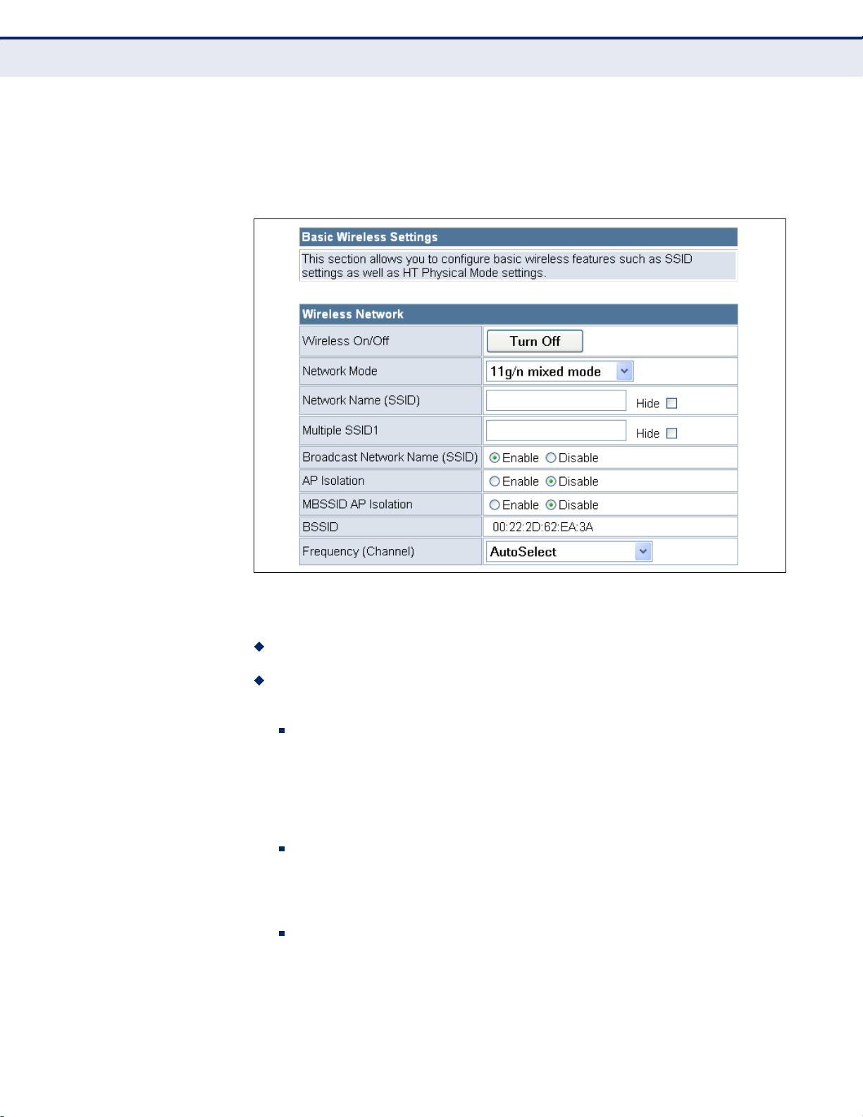
Figure 34: Basic Settings
The following items are displayed on this page:
Wireless O n / O f f — Enables or Disable the radio. (Default: Enable)
Network Mo d e — Defines the radio operating mode. (Default: 11g/n
Mixed)
11b/g mixe d : Both 802.11b and 802.11g clients can communicate
with the Mini Broadband Router (up to 108 Mbps), but data
transmission rates may be slowed to compensate for 802.11b
clients. Any 802.11n clients will also be able to communicate with
the Mini Broadband Router, but they will be limited to 802.11g
protocols and data transmission rates.
11b only : All 802.11b, 802.11g, and 802.11n clients will be able to
communicate with the Mini Broadband Router, but the 802.11g and
802.11n clients will be limited to 802.11b protocols and data
transmission rates (up to 11 Mbps).
11g only : Both 802.11g and 802.11n clients will be able to
communicate with the Mini Broadband Router, but the 802.11n
clients will be limited to 802.11g protocols and data transmission
rates (up to 54 Mbps). Any 802.11b clients will not be able to
communicate with the Mini Broadband Router.
– 65 –
Page 61

CHAPTER 7 |
Wireless Configuration
Basic Settings
11n only : Only 802.11n clients will be able to communicate with
the Mini Broadband Router (up to 150 Mbps).
11g/n mix e d : Both 802.11g and 802.11n clients can communicate
with the Mini Broadband Router (up to 150 Mbps), but data
transmission rates may be slowed to compensate for 802.11g
clients.
11b/g/n M i x e d : All 802.11b/g/n clients can communicate with the
Mini Broadband Router (up to 150 Mbps), but data transmission
rates may be slowed to compensate for 802.11b/g clients.
Network N a m e (SSID) — The name of the wireless network service
provided by the Mini Broadband Router. Clients that want to connect to
the network must set their SSID to the same as that of the Mini
Broadband Router. (Default: “ALFA”; Range: 1-32 characters)
Multiple S S I D 1 — One additional VAP interface supported on the
device. (Default: no name configured; Range: 1-32 characters)
Broadcast N e t work Nam e ( SSID) — By default, the Mini Broadband
Router always broadcasts the SSID in its beacon signal. Disabling the
SSID broadcast increases security of the network because wireless
clients need to already know the SSID before attempting to connect.
When set to disable, the Network Name SSID, and SSID1 are
automatically set to “Hide.” (Default: Enabled)
AP Isolat i o n — The Mini Broadband Router will isolate
communincation between all clients in order to protect them. Normally
for users who are at hotspots. (Default: Disabled)
MBSSID AP I s o lation — The Mini Broadband Router will isolate
wireless clients from different SSID.
BSSID — The identifier (MAC address) of the Mini Broadband Router in
the Basic Service Set (BSS) network.
Frequency ( C h annel) — The radio channel that the Mini Broadband
Router uses to communicate with wireless clients. When multiple
access points are deployed in the same area, set the channel on
neighboring access points at least five channels apart to avoid
interference with each other. For example, you can deploy up to three
access points in the same area using channels 1, 6, 11. Note that
wireless clients automatically set the channel to the same as that used
by the Mini Broadband Router to which it is linked. Selecting Auto
Select enables the Mini Broadband Router to automatically select an
unoccupied radio channel. (Default: AutoSelect)
– 66 –
Page 62

C
HAPTER
7
| Wireless Configuration
Basic Settings
HT PHYSICAL MODE
SETTINGS
The HT Physical Mode section on the Wireless Settings Advanced page
includes additional parameters for 802.11n operation.
Figure 35: HT Physical Mode Settings
The following items are displayed in this section on this page:
◆ HT Channel Bandwidth — The Mini Broadband Router provides a
channel bandwidth of 40 MHz by default giving an 802.11g connection
speed of 108 Mbps (sometimes referred to as Turbo Mode) and a
802.11n connection speed of up to 150 Mbps. Setting the HT Channel
Bandwidth to 20 MHz slows connection speed for 802.11g and 802.11n
to 54 Mbps and 74 Mbps respectively and ensures backward compliance
for slower 802.11b devices. (Default: 20MHz)
◆ Guard Interval — The guard interval between symbols helps receivers
overcome the effects of multipath delays. When you add a guard time,
the back portion of useful signal time is copied and appended to the
front. (Default: Auto)
◆ MCS — The Modulation and Coding Scheme (MCS) is a value that
determines the modulation, coding and number of spatial channels.
(Options: value [range] = 0~7 (1 Tx Stream), 8~15 (2 TxStream), 32
and auto (33). Default: auto)
◆ Reverse Direction Grant (RDG) — When Reverse Direction Grant is
enabled, the Mini Broadband Router can reduce the transmitted data
packet collision by using the reverse direction protocol. During TXOP
(Transmission Opportunity) period, the receiver could use remaining
transmission time to transmit data to a sender. The RDG improves
transmission performance and scalability in a wireless environment.
◆ Extension Channel — When 20/40MHz channel bandwidth has been
set, the extension channel option will be enabled. The extension
channel will allow you to get extra bandwidth. (Options: 2417MHz/
Channel 2, 2457MHz/Channel 10. Default: AutoSelect.)
– 67 –
Page 63

ADVANCED SETTINGS
C
HAPTER
7
| Wireless Configuration
Advanced Settings
◆ Aggregate MSDU (A-MSDU) — This option enables Mac Service Data
Unit (MSDU) aggregation. (Default: Disable)
◆ Auto Block ACK — Select to block ACK (Acknowledge Number) or not
during data transferring.
◆ Decline BA Request — Select to reject peer BA-Request or not.
The Advanced Settings page includes additional parameters concerning the
wireless network and Wi-Fi Multimedia settings.
N
OTE
:
There are several variables to consider when selecting a radio mode
that make it fully functional. Simply selecting the mode you want is not
enough to ensure full compatibility for that mode. Information on these
variables may be found in the HT Physcial Mode Setting section.
ADVANCED WIRELESS The Advanced Wireless section on the Wireless Settings Advanced page
includes additional radio parameters.
Figure 36: Advanced Wireless Settings
The following items are displayed in this section on this page:
◆ BG Protection Mode — Enables a backward compatible protection
mechanism for 802.11b clients. There are three modes: (Default: Auto)
– 68 –
Page 64

C
HAPTER
■
Auto — The unit enables its protection mechanism for 802.11b
7
| Wireless Configuration
Advanced Settings
clients when they are detected in the network. When 802.11b
clients are not detected, the protection mechanism is disabled.
■
On — Forces the unit to always use protection for 802.11b clients,
whether they are detected in the network or not. Note that enabling
b/g Protection can slow throughput for 802.11g/n clients by as
much as 50%.
■
Off — Forces the unit to never use protection for 802.11b clients.
This prevents 802.11b clients from connecting to the network.
◆ Beacon Interval — The rate at which beacon signals are transmitted
from the access point. The beacon signals allow wireless clients to
maintain contact with the access point. They may also carry powermanagement information. (Range: 20-999 TUs; Default: 100 TUs)
◆ Data Beacon Rate (DTIM) — The rate at which stations in sleep
mode must wake up to receive broadcast/multicast transmissions.
Known also as the Delivery Traffic Indication Map (DTIM) interval, it
indicates how often the MAC layer forwards broadcast/multicast traffic,
which is necessary to wake up stations that are using Power Save
mode. The default value of one beacon indicates that the access point
will save all broadcast/multicast frames for the Basic Service Set (BSS)
and forward them after every beacon. Using smaller DTIM intervals
delivers broadcast/multicast frames in a more timely manner, causing
stations in Power Save mode to wake up more often and drain power
faster. Using higher DTIM values reduces the power used by stations in
Power Save mode, but delays the transmission of broadcast/multicast
frames. (Range: 1-255 beacons; Default: 1 beacon)
◆ Fragmentation Threshold – Configures the minimum packet size that
can be fragmented when passing through the access point.
Fragmentation of the PDUs (Package Data Unit) can increase the
reliability of transmissions because it increases the probability of a
successful transmission due to smaller frame size. If there is significant
interference present, or collisions due to high network utilization, try
setting the fragment size to send smaller fragments. This will speed up
the retransmission of smaller frames. However, it is more efficient to
set the fragment size larger if very little or no interference is present
because it requires overhead to send multiple frames. (Range: 2562346 bytes; Default: 2346 bytes)
◆ RTS Threshold — Sets the packet size threshold at which a Request to
Send (RTS) signal must be sent to a receiving station prior to the
sending station starting communications. The access point sends RTS
frames to a receiving station to negotiate the sending of a data frame.
After receiving an RTS frame, the station sends a CTS (clear to send)
frame to notify the sending station that it can start sending data.
If the RTS threshold is set to 0, the access point always sends RTS
signals. If set to 2347, the access point never sends RTS signals. If set
to any other value, and the packet size equals or exceeds the RTS
– 69 –
Page 65

C
HAPTER
7
| Wireless Configuration
Advanced Settings
threshold, the RTS/CTS (Request to Send / Clear to Send) mechanism
will be enabled.
The access points contending for the medium may not be aware of each
other. The RTS/CTS mechanism can solve this “Hidden Node Problem.”
(Range: 1-2347 bytes: Default: 2347 bytes)
◆ Short Preamble — Sets the length of the signal preamble that is used
at the start of a data transmission. Use a short preamble (96
microseconds) to increase data throughput when it is supported by all
connected 802.11g clients. Use a long preamble (192 microseconds) to
ensure all 802.11b clients can connect to the network.
(Default: Disabled)
◆ Short Slot — Sets the basic unit of time the access point uses for
calculating waiting times before data is transmitted. A short slot time
(9 microseconds) can increase data throughput on the access point, but
requires that all clients can support a short slot time (that is, 802.11gcompliant clients must support a short slot time). A long slot time
(20 microseconds) is required if the access point has to support
802.11b clients. (Default: Enabled)
◆ TX Burst — A performance enhancement that transmits a number of
data packets at the same time when the feature is supported by
compatible clients. (Default: Enabled)
◆ Packet Aggregate — A performance enhancement that combines data
packets together when the feature is supported by compatible clients.
(Default: Enabled)
WI-FI MULTIMEDIA The Mini Broadband Router implements Quality of Service (QoS) using the
Wi-Fi Multimedia (WMM) standard. Using WMM, the access point is able to
prioritize traffic and optimize performance when multiple applications
compete for wireless network bandwidth at the same time. WMM employs
techniques that are a subset of the developing IEEE 802.11e QoS standard
and it enables access points to interoperate with both WMM-enabled clients
and other devices that may lack any WMM functionality.
WMM defines four access categories (ACs): voice, video, best effort, and
background. These categories correspond to traffic priority levels and are
mapped to IEEE 802.1D priority tags (see Tab le 3 ). The direct mapping of
the four ACs to 802.1D priorities is specifically intended to facilitate
interoperability with other wired network QoS policies. While the four ACs
are specified for specific types of traffic, WMM allows the priority levels to
be configured to match any network-wide QoS policy. WMM also specifies a
protocol that access points can use to communicate the configured traffic
priority levels to QoS-enabled wireless clients.
– 70 –
Page 66

Table 3: WMM Access Categories
C
HAPTER
7
| Wireless Configuration
Advanced Settings
Access
Category
AC_VO (AC3) Voice Highest priority, minimum delay. Time-sensitive
AC_VI (AC2) Video High priority, minimum delay. Time-sensitive
AC_BE (AC0) Best Effort Normal priority, medium delay and throughput.
AC_BK (AC1) Background Lowest priority. Data with no delay or
WMM
Designation
Description 802.1D
data such as VoIP (Voice over IP) calls.
data such as streaming video.
Data only affected by long delays. Data from
applications or devices that lack QoS
capabilities.
throughput requirements, such as bulk data
transfers.
Tags
7, 6
5, 4
0, 3
2, 1
The Wi-Fi Multimedia section on the Wireless Settings Advanced page
allows you to enable WMM and set detailed QoS parameters.
Figure 37: Wi-Fi Multimedia Settings
The following items are displayed in this section on this page:
◆ WMM — Sets the WMM operational mode on the access point. When
enabled, the QoS capabilities are advertised to WMM-enabled clients in
the network. WMM must be supported on any device trying to
associated with the access point. Devices that do not support this
feature will not be allowed to associate with the access point.
(Default: Enabled)
◆ APSD — When WMM is enabled, Automatic Power Save Delivery
(APSD) can also be enabled. APSD is an efficient power management
method that enables client devices sending WMM packets to enter a
low-power sleep state between receiving and transmitting data.
(Default: Disabled)
◆ WMM Parameters — Click the WMM Configuration button to set
detailed WMM parameters.
– 71 –
Page 67

Figure 38: WMM Configuration
C
HAPTER
7
| Wireless Configuration
Advanced Settings
The following items are displayed in the WMM Configuration window:
◆ AIFSN (Arbitration Inter-Frame Space) — The minimum amount of
wait time before the next data transmission attempt. Specify the AIFS
value in the range 0-15 microseconds.
◆ CWMin (Minimum Contention Window) — The initial upper limit of the
random backoff wait time before wireless medium access can be
attempted. The initial wait time is a random value between zero and
the CWMin value. Specify the CWMin value in the range 0-15
microseconds. Note that the CWMin value must be equal or less than
the CWMax value.
◆ CWMax (Maximum Contention Window) — The maximum upper limit
of the random backoff wait time before wireless medium access can be
attempted. The contention window is doubled after each detected
collision up to the CWMax value. Specify the CWMax value in the range
0-15 microseconds. Note that the CWMax value must be greater or
equal to the CWMin value.
◆ Txop (Transmit Opportunity Limit) — The maximum time an AC
transmit queue has access to the wireless medium. When an AC queue
is granted a transmit opportunity, it can transmit data for a time up to
the TxOpLimit. This data bursting greatly improves the efficiency for
high data-rate traffic. Specify a value in the range 0-65535
microseconds.
– 72 –
Page 68

C
HAPTER
7
| Wireless Configuration
Advanced Settings
◆ ACM — The admission control mode for the access category. When
enabled, clients are blocked from using the access category.
(Default: Disabled)
◆ AckPolicy — By default, all wireless data transmissions require the
sender to wait for an acknowledgement from the receiver. WMM allows
the acknowledgement wait time to be turned off for each Access
Category (AC) 0-3. Although this increases data throughput, it can also
result in a high number of errors when traffic levels are heavy.
(Default: Acknowledge)
MULTICAST-TO-
UNICAST CONVERTER
The Multicast-to-Unicast Converter section on the Wireless Settings
Advanced page allows you to enable multicast traffic conversion.
Converting multicast traffic to unicast before sending to wireless clients
allows a longer DTIM (Data Beacon Rate) interval to be set. A longer DTIM
interval prevents clients in power-save mode having to activate their radios
to receive the multicast data, which saves battery life.
Figure 39: Multicast-to-Unicast Converter
The following items are displayed in this section on this page:
◆ Multicast-to-Unicast — Enables multicast traffic streams to be
converted to unicast traffic before delivery to wireless clients.
(Default: Disabled)
– 73 –
Page 69

WLAN SECURITY
CHAPTER 7 |
The Mini Broadband Router’s wireless interface is configured by default as
an “open system,” which broadcasts a beacon signal including the
configured SSID. Wireless clients with a configured SSID of “ANY” can read
the SSID from the beacon, and automatically set their SSID to allow
immediate connection to the wireless network.
To implement wireless network security, you have to employ one or both of
the following functions:
Authentica t i o n — It must be verified that clients attempting to
connect to the network are authorized users.
Traffic En c r y p tion — Data passing between the unit and clients must
be protected from interception and eavesdropping.
The Mini Broadband Router supports supports ten different security
mechanisms that provide various levels of authentication and encryption
depending on the requirements of the network.
Wireless Configuration
WLAN Security
The Mini Broadband Router supports two SSID interfaces. Each SSID
interface functions as a separate access point, and can be configured with
its own security settings.
Click on “Wireless Settings,” followed by “Basic”.
Figure 40: Security Mode Options
– 74 –
Page 70

C
HAPTER
7
| Wireless Configuration
WLAN Security
The supported security mechanisms and their configuration parameters are
described in the following sections:
◆ OPEN, SHARED, WEP-AUTO — See “Wired Equivalent Privacy (WEP)”
on page 75
◆ WPA-PSK, WPA2-PSK, WPA-PSK_WPA2-PSK — See “WPA Pre-
Shared Key” on page 76
◆ WPA, WPA2, WPA1_WPA2 — See “WPA Enterprise Mode” on
page 77
◆ 802.1X — See “IEEE 802.1X and RADIUS” on page 79
WIRED EQUIVALENT
PRIVACY (WEP)
WEP provides a basic level of security, preventing unauthorized access to
the network, and encrypting data transmitted between wireless clients and
an access point. WEP uses static shared keys (fixed-length hexadecimal or
alphanumeric strings) that are manually distributed to all clients that want
to use the network.
When you select to use WEP, be sure to define at least one static WEP key
for user authentication or data encryption. Also, be sure that the WEP
shared keys are the same for each client in the wireless network.
Figure 41: Security Mode - WEP
The following items are displayed in this section on this page:
Security Mode — Configures the WEP security mode used by clients.
When using WEP, be sure to define at least one static WEP key for the Mini
Broadband Router and all its clients. (Default: Disable)
◆ OPEN — Open-system authentication accepts any client attempting to
connect the Mini Broadband Router without verifying its identity. In this
mode the default data encryption type is “WEP.”
◆ SHARED — The shared-key security uses a WEP key to authenticate
clients connecting to the network and for data encryption.
– 75 –
Page 71

C
HAPTER
7
| Wireless Configuration
WLAN Security
◆ WEP-AUTO — Allows wireless clients to connect to the network using
Open-WEP (uses WEP for encryption only) or Shared-WEP (uses WEP
for authentication and encryption).
◆ Encrypt Type — Selects WEP for data encryption (OPEN mode only).
◆ Default Key — Selects the WEP key number to use for authentication
or data encryption. If wireless clients have all four WEP keys configured
to the same values, you can change the encryption key to any of the
settings without having to update the client keys. (Default: 1;
Range: 1~4)
◆ WEP Keys 1 ~ 4 — Sets WEP key values. The user must first select
ASCII or hexadecimal keys. Each WEP key has an index number. Enter
key values that match the key type and length settings. Enter 5
alphanumeric characters or 10 hexadecimal digits for 64-bit keys, or
enter 13 alphanumeric characters or 26 hexadecimal digits for 128-bit
keys. (Default: Hex, no preset value)
WPA PRE-SHARED
KEY
Wi-Fi Protected Access (WPA) was introduced as an interim solution for the
vulnerability of WEP pending the adoption of a more robust wireless
security standard. WPA2 includes the complete wireless security standard,
but also offers backward compatibility with WPA. Both WPA and WPA2
provide an “enterprise” and “personal” mode of operation.
For small home or office networks, WPA and WPA2 provide a simple
“personal” operating mode that uses just a pre-shared key for network
access. The WPA Pre-Shared Key (WPA-PSK) mode uses a common
password phrase for user authentication that is manually entered on the
access point and all wireless clients. Data encryption keys are
automatically generated by the access point and distributed to all clients
connected to the network.
Figure 42: Security Mode - WPA-PSK
The following items are displayed in this section on this page:
Security Mode — Configures the WPA-PSK and WPA2-PSK security modes
used by clients. When using WPA-PSK or WPA2-PSK, be sure to define the
shared key for the Mini Broadband Router and all its clients.
(Default: Disable)
– 76 –
Page 72

C
HAPTER
7
| Wireless Configuration
WLAN Security
◆ WPA-PSK — Clients using WPA with a Pre-shared Key are accepted for
authentication. The default data encryption type for WPA is TKIP.
◆ WPA2-PSK — Clients using WPA2 with a Pre-shared Key are accepted
for authentication. The default data encryption type for WPA is AES.
◆ WPA-PSK_WPA2-PSK — Clients using WPA or WPA2 with a Pre-
shared Key are accepted for authentication. The default data encryption
type is TKIP/AES.
◆ WPA Algorithms — Selects the data encryption type to use. (Default
is determined by the Security Mode selected.)
■
TKIP — Uses Temporal Key Integrity Protocol (TKIP) keys for
encryption. WPA specifies TKIP as the data encryption method to
replace WEP. TKIP avoids the problems of WEP static keys by
dynamically changing data encryption keys.
■
AES — Uses Advanced Encryption Standard (AES) keys for
encryption. WPA2 uses AES Counter-Mode encryption with Cipher
Block Chaining Message Authentication Code (CBC-MAC) for
message integrity. The AES Counter-Mode/CBCMAC Protocol (AESCCMP) provides extremely robust data confidentiality using a 128bit key. Use of AES-CCMP encryption is specified as a standard
requirement for WPA2. Before implementing WPA2 in the network,
be sure client devices are upgraded to WPA2-compliant hardware.
WPA ENTERPRISE
MODE
■
TKIP/AES — Uses either TKIP or AES keys for encryption. WPA and
WPA2 mixed modes allow both WPA and WPA2 clients to associate
to a common SSID. In mixed mode, the unicast encryption type
(TKIP or AES) is negotiated for each client.
◆ Pass Phrase — The WPA Preshared Key can be input as an ASCII
string (an easy-to-remember form of letters and numbers that can
include spaces) or Hexadecimal format. (Range: 8~63 ASCII
characters, or exactly 64 Hexadecimal digits)
◆ Key Renewal Interval — Sets the time period for automatically
changing data encryption keys and redistributing them to all connected
clients. (Default: 3600 seconds)
Wi-Fi Protected Access (WPA) was introduced as an interim solution for the
vulnerability of WEP pending the adoption of a more robust wireless
security standard. WPA2 includes the complete wireless security standard,
but also offers backward compatibility with WPA. Both WPA and WPA2
provide an “enterprise” and “personal” mode of operation.
For enterprise deployment, WPA and WPA2 use IEEE 802.1X for user
authentication and require a RADIUS authentication server to be
configured on the wired network. Data encryption keys are automatically
generated and distributed to all clients connected to the network.
– 77 –
Page 73

Figure 43: Security Mode - WPA
C
HAPTER
7
| Wireless Configuration
WLAN Security
The following items are displayed in this section on this page:
Security Mode — Configures the WPA and WPA2 security modes used by
clients. When using WPA or WPA2, be sure there is a RADIUS server in the
connected wired network, and that the RADIUS settings are configured.
See “IEEE 802.1X and RADIUS” on page 79 for more information.
(Default: Disable)
◆ WPA — Clients using WPA with an 802.1X authentication method are
accepted for authentication. The default data encryption type for WPA
is TKIP.
◆ WPA2 — Clients using WPA2 with an 802.1X authentication method
are accepted for authentication. The default data encryption type for
WPA is AES.
◆ WPA1_WPA2 — Clients using WPA or WPA2 with an 802.1X
authentication method are accepted for authentication. The default
data encryption type is TKIP/AES.
◆ WPA Algorithms — Selects the data encryption type to use. (Default
is determined by the Security Mode selected.)
■
TKIP — Uses Temporal Key Integrity Protocol (TKIP) keys for
encryption. WPA specifies TKIP as the data encryption method to
replace WEP. TKIP avoids the problems of WEP static keys by
dynamically changing data encryption keys.
■
AES — Uses Advanced Encryption Standard (AES) keys for
encryption. WPA2 uses AES Counter-Mode encryption with Cipher
Block Chaining Message Authentication Code (CBC-MAC) for
– 78 –
Page 74

C
HAPTER
7
| Wireless Configuration
WLAN Security
message integrity. The AES Counter-Mode/CBCMAC Protocol (AESCCMP) provides extremely robust data confidentiality using a 128bit key. Use of AES-CCMP encryption is specified as a standard
requirement for WPA2. Before implementing WPA2 in the network,
be sure client devices are upgraded to WPA2-compliant hardware.
■
TKIP/AES — Uses either TKIP or AES keys for encryption. WPA and
WPA2 mixed modes allow both WPA and WPA2 clients to associate
to a common SSID. In mixed mode, the unicast encryption type
(TKIP or AES) is negotiated for each client.
◆ Key Renewal Interval — Sets the time period for automatically
changing data encryption keys and redistributing them to all connected
clients. (Default: 3600 seconds)
◆ PMK Cache Period — WPA2 provides fast roaming for authenticated
clients by retaining keys and other security information in a cache, so
that if a client roams away from an access point and then returns
reauthentication is not required. This parameter sets the time for
deleting the cached WPA2 Pairwise Master Key (PMK) security
information. (Default: 10 minutes)
IEEE 802.1X AND
RADIUS
◆ Pre-Authentication — When using WPA2, pre-authentication can be
enabled that allows clients to roam to another access point and be
quickly associated without performing full 802.1X authentication.
(Default: Disabled)
IEEE 802.1X is a standard framework for network access control that uses
a central RADIUS server for user authentication. This control feature
prevents unauthorized access to the network by requiring an 802.1X client
application to submit user credentials for authentication. The 802.1X
standard uses the Extensible Authentication Protocol (EAP) to pass user
credentials (either digital certificates, user names and passwords, or other)
from the client to the RADIUS server. Client authentication is then verified
on the RADIUS server before the client can access the network.
Remote Authentication Dial-in User Service (RADIUS) is an authentication
protocol that uses software running on a central server to control access to
RADIUS-aware devices on the network. An authentication server contains a
database of user credentials for each user that requires access to the
network.
The WPA and WPA2 enterprise security modes use 802.1X as the method
of user authentication. IEEE 802.1X can also be enabled on its own as a
security mode for user authentication. When 802.1X is used, a RADIUS
server must be configured and be available on the connected wired
network.
N
OTE
:
This guide assumes that you have already configured RADIUS
server(s) to support the access point. Configuration of RADIUS server
software is beyond the scope of this guide, refer to the documentation
provided with the RADIUS server software.
– 79 –
Page 75

Figure 44: Security Mode - 802.1X
C
HAPTER
7
| Wireless Configuration
WLAN Security
The following items are displayed in this section on this page:
Security Mode — Configures the 802.1X security mode used by clients.
When using 802.1X, either with WPA/WPA2 or on its own, be sure there is
a configured RADIUS server in the connected wired network.
(Default: Disable)
802.1X WEP: Selects WEP keys for data encryption. When enabled, WEP
encryption keys are automatically generated by the RADIUS server and
distributed to all connected clients. (Default: Disabled)
RADIUS Server — Configures RADIUS server settings.
◆ IP Address — Specifies the IP address of the RADIUS server.
◆ Port — The User Datagram Protocol (UDP) port number used by the
RADIUS server for authentication messages. (Range: 1024-65535;
Default: 1812)
◆ Shared Secret — A shared text string used to encrypt messages
between the access point and the RADIUS server. Be sure that the
same text string is specified on the RADIUS server. Do not use blank
spaces in the string. (Maximum length: 20 characters)
◆ Session Timeout — Number of seconds the access point waits for a
reply from the RADIUS server before resending a request. (Range: 160 seconds; Default: 0)
◆ Idle Timeout — Sets the maximum time (in seconds) of client
inactivity before a session is terminated.
– 80 –
Page 76
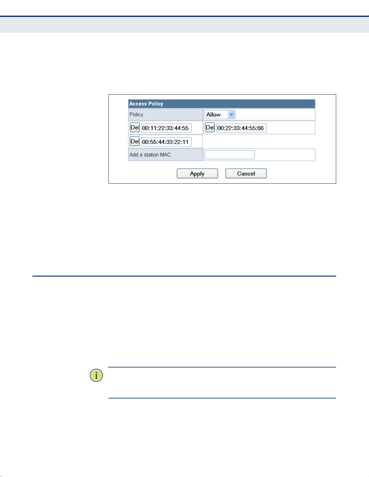
C
HAPTER
Wireless Distribution System (WDS)
7
| Wireless Configuration
ACCESS POLICY The Mini Broadband Router provides a MAC address filtering facility. The
access policy can be set to allow or reject specific station MAC addresses.
This feature can be used to connect known wireless devices that may not
be able to support the configured security mode.
Figure 45: Access Policy
The following items are displayed in this section on this page:
◆ Access Policy — The access policy can be set to allow or reject specific
station MAC addresses.
◆ Add a station MAC — Enter the MAC address of the station that you
want to filter. MAC addresses must be entered in the format
xx:xx:xx:xx:xx:xx.
WIRELESS DISTRIBUTION SYSTEM (WDS)
The radio interface can be configured to operate in a mode that allows it to
forward traffic directly to other Mini Broadband Router units. This feature
can be used to extend the range of the wireless network to reach remote
clients, or to link disconnected network segments to an Internet
connection.
To set up links between units, you must configure the Wireless Distribution
System (WDS) forwarding table by specifying the wireless MAC address of
all units to which you want to forward traffic.
N
OTE
:
All units in a WDS wireless network must be configured with the
same SSID and use the same radio channel. Also each WDS link must be
configured with the same encryption key on both units in the link.
Up to four WDS links can be specified for each unit in the WDS network.
The following figures illustrate an example WDS network. Figure 46 shows
the manual set up of MAC addresses for units in the WDS network.
Figure 47 shows the basic configuration required on each unit in the WDS
network.
– 81 –
Page 77

C
Internet
Service
Provider
MAC: 00-22-2D-62-EA-11
WDS MAC List:
00-22-2D-62-EA-22
00-22-2D-62-EA-33
00-22-2D-62-EA-44
MAC: 00-22-2D-62-EA-22
WDS MAC List:
00-22-2D-62-EA-11
Cable/DSL
Modem
WDS Link
MAC: 00-22-2D-62-EA-33
WDS MAC List:
00-22-2D-62-EA-11
MAC: 00-22-2D-62-EA-44
WDS MAC List:
00-22-2D-62-EA-11
WDS Link
WDS Link
Internet
Service
Provider
Operation Mode: Router
DHCP Server: Enable
LAN IP Address: 192.168.2.1
WDS Mode: Bridge
Operation Mode: Bridge
WDS Mode: Repeater
DHCP Server: Disable
LAN IP Address: 192.168.2.2
Cable/DSL
Modem
WDS Link
Operation Mode: Bridge
WDS Mode: Lazy
DHCP Server: Disable
LAN IP Address: 192.168.2.3
Operation Mode:
WDS Mode: Lazy
DHCP Server: Disable
LAN IP Address: 192.168.2.4
Router
WDS Link
WDS Link
HAPTER
7
Wireless Distribution System (WDS)
Figure 46: Manual WDS MAC Address Configuration
Figure 47: WDS Configuration Example
| Wireless Configuration
A WDS link between two units can be configured in any of the following
Operation Mode combinations:
1. Both units in a link are configured as Router Mode.
2. One unit in a link is configured in Router Mode and the other in Bridge
3. Both units in a link are configured as Bridge Mode.
When two or more units in the WDS network are set to Router Mode, be
sure to check these settings:
◆ Be sure each unit is configured with a different LAN IP address.
Mode.
– 82 –
Page 78

C
HAPTER
Wireless Distribution System (WDS)
7
| Wireless Configuration
◆ Be sure that only one unit has an Internet access on its WAN port.
◆ Be sure the DHCP server is enabled only on one unit. When one unit is
providing Internet access, enable the DHCP server on that unit.
N
OTE
:
When using WDS Lazy mode in the network, at least one unit must
be set to Bridge or Repeater mode.
Figure 48: WDS Configuration
The WDS settings configure WDS related parameters. Up to four MAC
addresses can be specified for each unit in the WDS network. WDS links
may either be manually configured (Bridge and Repeater modes) or autodiscovered (Lazy mode).
The following items are displayed on this page:
◆ WDS Mode — Selects the WDS mode of the SSID. (Options: Disable,
Lazy, Bridge, Repeater. Default: Disable)
■
Disable: WDS is disabled.
■
Lazy: Operates in an automatic mode that detects and learns WDS
peer addresses from received WDS packets, without the need to
– 83 –
Page 79

C
HAPTER
7
| Wireless Configuration
Wi-Fi Protected Setup (WPS)
configure a WDS MAC list entry. This feature allows the Mini
Broadband Router to associate with other Mini Broadband Routers
in the network and use their WDS MAC list. Lazy mode requires one
other Mini Broadband Router within the wireless network that is
configured in Bridge or Repeater mode, and has a configured MAC
address list.
■
Bridge: Operates as a standard bridge that forwards traffic
between WDS links (links that connect to other units in Repeater or
Lazy mode). The MAC addresses of WDS peers must be configured
on the Mini Broadband Router.
■
Repeater: Operates as a wireless repeater, extending the range for
remote wireless clients and connecting them to an AP connected to
the wired network. The MAC addresses of WDS peers must be
configured on the Mini Broadband Router.
◆ Physical — The radio media coding used on all WDS links. CCK
corresponds to 11b, OFDM corresponds to 11g, and HTMIX corresponds
to 11n.
◆ Encryption Type — The data encryption used on the WDS link. Be
sure that both ends of a WDS link are configured with the same
encryption type and key. (Options: None, WEP, TKIP, AES.
Default: None)
◆ Encryption Key — The encryption key for the WDS link. The key type
and length varies depending on the encryption type selected. For WEP,
enter 5 alphanumeric characters or 10 hexadecimal digits for 64-bit
keys, or 13 alphanumeric characters or 26 hexadecimal digits for 128bit keys. For TKIP or AES, enter a password key phrase of between 8 to
63 ASCII characters, which can include spaces, or specify exactly 64
hexadecimal digits.
◆ AP MAC Address — The MAC address of the other Mini Broadband
Router in the WDS link.
WI-FI PROTECTED SETUP (WPS)
Wi-Fi Protected Setup (WPS) is designed to ease installation and activation
of security features in wireless networks. WPS has two basic modes of
operation, Push-button Configuration (PBC) and Personal Identification
Number (PIN). The WPS PIN setup is optional to the PBC setup and
provides more security. The WPS button on the Mini Broadband Router can
be pressed at any time to allow a single device to easily join the network.
The WPS Settings page includes configuration options for setting WPS
device PIN codes and activating the virtual WPS button.
Click on “Wireless Settings,” followed by “WPS”.
– 84 –
Page 80

C
HAPTER
Figure 49: Enabling WPS
7
| Wireless Configuration
Wi-Fi Protected Setup (WPS)
The following items are displayed on this page:
◆ WPS — Enables WPS, locks security settings, and refreshes WPS
configuration information. (Default: Disabled)
Figure 50: WPS Configuration
– 85 –
Page 81

C
HAPTER
7
| Wireless Configuration
Wi-Fi Protected Setup (WPS)
The following items are displayed on this page:
WPS Summary — Provides detailed WPS statistical information.
◆ WPS Current Status — Displays if there is currently any WPS traffic
connecting to the Mini Broadband Router. (Options: Start WSC Process;
Idle)
◆ WPS Configured — States if WPS for wireless clients has been
configured for this device.
◆ WPS SSID — The service set identifier for the unit.
◆ WPS Auth Mode — The method of authentication used.
◆ WPS Encryp Type — The encryption type used for the unit.
◆ WPS Default Key Index — Displays the WEP default key (1~4).
◆ WPS Key (ASCII) — Displays the WPS security key (ASCII) which can
be used to ensure the security of the wireless network.
◆ AP PIN — Displays the PIN Code for the Mini Broadband Router. The
default is exclusive for each unit. (Default: 64824901)
◆ Reset WPS to Default — Resets the WPS settings to factory default
values.
WPS Config — Configures WPS settings for the Mini Broadband Router.
◆ WPS Mode — Selects between methods of broadcasting the WPS
beacon to network clients wanting to join the network:
■
PIN: The Mini Broadband Router, along with other WPS devices,
such as notebook PCs, cameras, or phones, all come with their own
eight-digit PIN code. When one device, the WPS enrollee, sends a
PIN code to the Mini Broadband Router, it becomes the WPS
registrar. After configuring PIN-Code information you must press
“Apply” to send the beacon, after which you have up to two minutes
to activate WPS on devices that need to join the network.
■
PBC: This has the same effect as pressing the physical WPS button
that is located on the front of the Mini Broadband Router. After
checking this option and clicking “Apply” you have up to two
minutes to activate WPS on devices that need to join the network.
– 86 –
Page 82
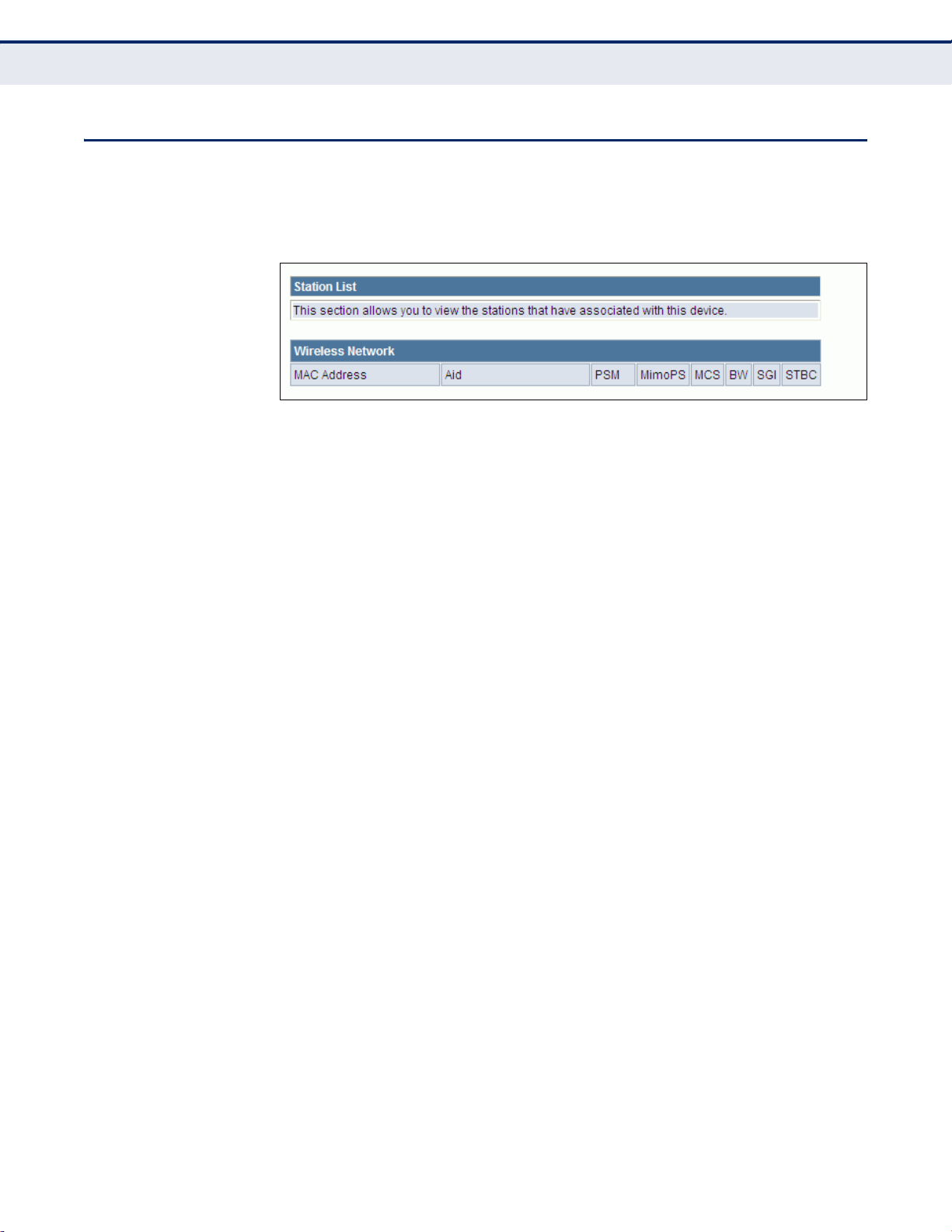
STATION LIST
C
HAPTER
7
| Wireless Configuration
Station List
Displays the station information which associated to this Mini Broadband
Router.
Figure 51: Station List
– 87 –
Page 83

8 FIREWALL CONFIGURATION
The Mini Broadband Router provides extensive firewall protection by
restricting connection parameters to limit the risk of intrusion and
defending against a wide array of common hacker attacks.
Firewall Configuration contains the following sections:
◆ “MAC/IP/Port Filtering” on page 88
◆ “Virtual Server Settings (Port Forwarding)” on page 91
◆ “DMZ” on page 92
◆ “System Security” on page 93
◆ “Content Filtering” on page 94
MAC/IP/PORT FILTERING
MAC/IP/Port filtering restricts connection parameters to limit the risk of
intrusion and defends against a wide array of common hacker attacks.
MAC/IP/Port filtering allows the unit to permit, deny or proxy traffic
through its MAC addresses, IP addresses and ports.
The Mini Broadband Router allows you define a sequential list of permit or
deny filtering rules (up to 32). This device tests ingress packets against the
filter rules one by one. A packet will be accepted as soon as it matches a
permit rule, or dropped as soon as it matches a deny rule. If no rules
match, the packet is either accepted or dropped depending on the default
policy setting.
– 88 –
Page 84

Figure 52: MAC/IP/Port Filtering
C
HAPTER
8
| Firewall Configuration
MAC/IP/Port Filtering
The following items are displayed on this page:
◆ MAC/IP/Port Filtering — Enables or disables MAC/IP/Port Filtering.
(Default: Disable)
◆ Default Policy — When MAC/IP/Port Filtering is enabled, the default
policy will be enabled. If you set the default policy to “Dropped”, all
incoming packets that don’t match the rules will be dropped. If the
policy is set to "Accepted," all incoming packets that don't match the
rules are accepted. (Default: Dropped)
◆ MAC Address — Specifies the MAC address to block or allow traffic
from.
– 89 –
Page 85

C
HAPTER
8
| Firewall Configuration
MAC/IP/Port Filtering
◆ Destination IP Address — Specifies the destination IP address to
block or allow traffic from.
◆ Source IP Address — Specifies the source IP address to block or allow
traffic from.
◆ Protocol — Specifies the destination port type, TCP, UDP or ICMP.
(Default: None).
◆ Destination Port Range — Specifies the range of destination port to
block traffic from the specified LAN IP address from reaching.
◆ Source Port Range — Specifies the range of source port to block
traffic from the specified LAN IP address from reaching.
◆ Action — Specifies if traffic should be accepted or dropped. (Default:
Accept)
◆ Comment — Enter a useful comment to help identify the filtering rules.
CURRENT FILTER
RULES
The Current Filter Table displays the configured IP addresses and ports that
are permitted or denied access to and from the Mini Broadband Router.
◆ Select — Selects a table entry.
◆ MAC Address — Displays a MAC address to filter.
◆ Destination IP Address — Displays the destination IP address.
◆ Source IP Address — Displays the source IP address.
◆ Protocol — Displays the destination port type.
◆ Destination Port Range — Displays the destination port range.
◆ Source Port Range — Displays the source port range.
◆ Action — Displays if the specified traffic is accepted or dropped.
◆ Comment — Displays a useful comment to identify the routing rules.
– 90 –
Page 86

VIRTUAL SERVER SETTINGS (PORT FORWARDING)
Virtual Server (sometimes referred to as Port Forwarding) is the act of
forwarding a network port from one network node to another. This
technique can allow an external user to reach a port on a private IP
address (inside a LAN) from the outside through a NAT-enabled router.
(Maximum 32 entries are allowed.)
Figure 53: Virtual Server
C
HAPTER
Virtual Server Settings (Port Forwarding)
8
| Firewall Configuration
The following items are displayed on this page:
◆ Virtual Server Settings — Selects between enabling or disabling port
forwarding the virtual server. (Default: Disable)
◆ IP Address — Specifies the IP address on the local network to allow
external access.
◆ Port Range — Specifies the port range through which traffic is
forwarded.
◆ Protocol — Specifies a protocol to use for port forwarding, either TCP,
UDP or TCP&UDP.
◆ Comment — Enter a useful comment to help identify the forwarded
port service on the network.
– 91 –
Page 87

C
HAPTER
8
| Firewall Configuration
DMZ
CURRENT VIRTUAL
SERVERS IN SYSTEM
DMZ
The Current Port Forwarding Table displays the entries that are allowed to
forward packets through the Mini Broadband Router’s firewall.
◆ No. — The table entry number.
◆ IP Address — Displays an IP address on the local network to allow
external access to.
◆ Port Mapping — Displays the port the server is mapped.
◆ Protocol — Displays the protocol used for forwarding of this port.
◆ Comment — Displays a useful comment to identify the nature of the
port to be forwarded.
Enables a specified host PC on the local network to access the Internet
without any firewall protection. Some Internet applications, such as
interactive games or video conferencing, may not function properly behind
the Mini Broadband Router's firewall. By specifying a Demilitarized Zone
(DMZ) host, the PC's TCP ports are completely exposed to the Internet,
allowing open two-way communication. The host PC should be assigned a
static IP address (which is mapped to its MAC address) and this must be
configured as the DMZ IP address.
Figure 54: DMZ
The following items are displayed on this page:
◆ DMZ Settings — Sets the DMZ status. (Default: Disable)
◆ DMZ IP Address — Specifies an IP address on the local network
allowed unblocked access to the WAN.
– 92 –
Page 88

SYSTEM SECURITY
C
HAPTER
8
| Firewall Configuration
System Security
The Mini Broadband Router includes the facility to manage it from a remote
location. The unit can also be sent a ping message from a remote location.
Figure 55: System Security
The following items are displayed on this page:
◆ Remote Management — Denies or allows management access to the
Mini Broadband Router through the WAN interface. (Default: Deny)
◆ Ping from WAN Filter — When enabled, the Mini Broadband Router
does not respond to ping packets received on the WAN port.
(Default: Disable)
◆ Stateful Packet Inspection (SPI) — The Stateful Packet Inspection
(SPI) firewall protects your network and computers against attacks and
intrusions. A stateful packet firewall looks at packet contents to check if
the traffic may involve some type of security risk. (Default: Enable)
– 93 –
Page 89

CONTENT FILTERING
C
HAPTER
8
| Firewall Configuration
Content Filtering
The Mini Broadband Router provides a variety of options for blocking
Internet access based on content, URL and host name.
Figure 56: Content Filtering
The following items are displayed on this page:
Web URL Filter Settings — By filtering inbound Uniform Resource
Locators (URLs) the risk of compromising the network can be reduced.
URLs are commonly used to point to websites. By specifying a URL or a
keyword contained in a URL traffic from that site may be blocked.
◆ Current URL Filters — Displays current URL filter.
◆ Add a URL Filter — Adds a URL filter to the settings. For example,
myhost.example.com.
Web Host Filter Settings — The Mini Broadband Router allows Internet
content access to be restricted based on web address keywords and web
domains. A domain name is the name of a particular web site. For
example, for the address www.FUNGAMES.com, the domain name is
FUNGAMES.com. Enter the Keyword then click “Add.”
– 94 –
Page 90

C
HAPTER
8
| Firewall Configuration
Content Filtering
◆ Current Host Filters — Displays current Host filter.
◆ Add a Host Filter — Enters the keyword for a host filtering.
– 95 –
Page 91

9 ADMINISTRATION SETTINGS
The Mini Broadband Router’s Administration Settings menu provides the
same configuration options in both Router and Bridge Mode. These settings
allow you to configure a management access password, set the system
time, upgrade the system software, display the system status and
statistics.
Administration Settings contains the following sections:
◆ “System Management” on page 97
◆ “Time Zone Settings” on page 98
◆ “DDNS Settings” on page 99
◆ “Firmware Upgrade” on page 100
◆ “Configuration Settings” on page 101
◆ “System Status” on page 102
◆ “Statistics” on page 104
◆ “System Log” on page 105
– 96 –
Page 92
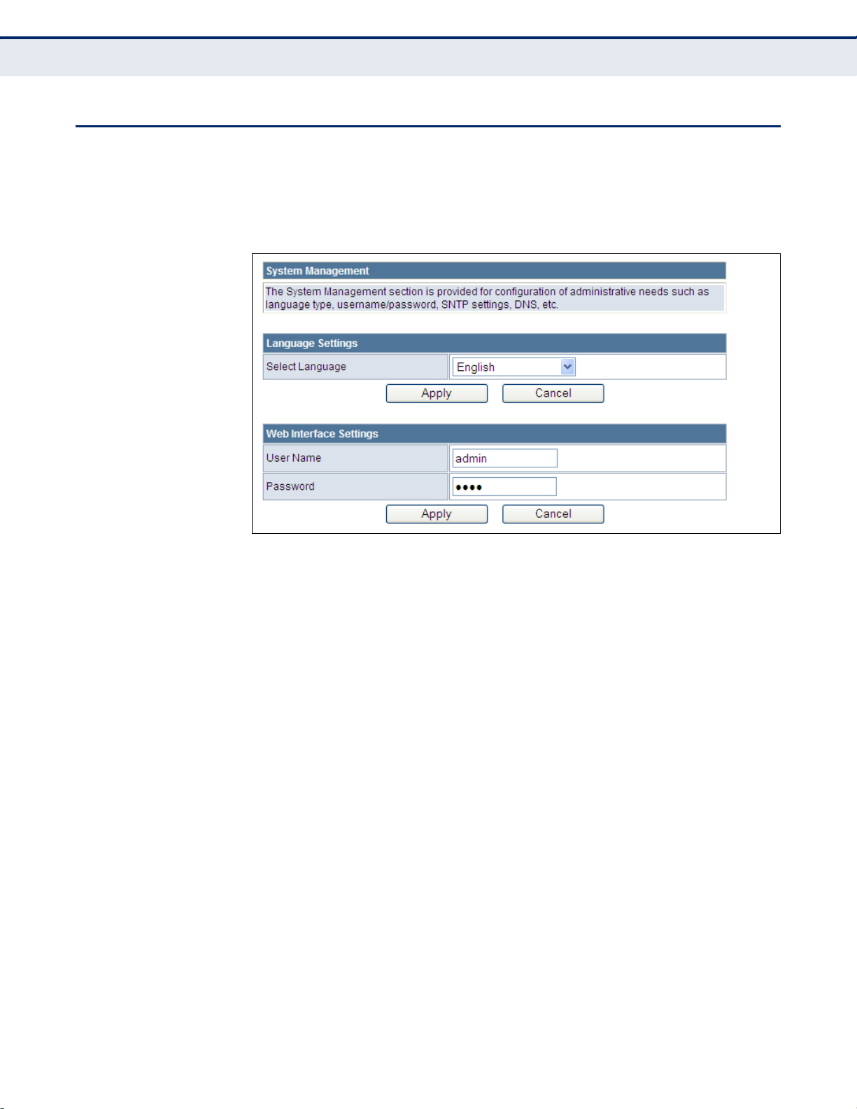
SYSTEM MANAGEMENT
The System Management commands allow you to change the language
settings displayed in the interface, and change the user name and
password.
Figure 57: System Management
C
HAPTER
9
| Administration Settings
System Management
The following items are displayed in the first two sections on this page:
◆ Language Settings — You can change the language displayed in web
interface. Select the language of your choice from the drop-down list,
then click “Apply.” (Options: English, Traditional Chinese, Simple
Chinese, or Korean. Default: English)
◆ Web Interface Settings — To protect access to the management
interface, you need to configure a new Administrator’s user name and
password as soon as possible. If a new user name and password are
not configured, then anyone having access to the Mini Broadband
Router may be able to compromise the unit's security by entering the
default values.
■
User Name — The name of the user. The default name for access
to the unit is “admin.” (Length: 3-16 characters, case sensitive)
■
Password — The password for management access. The default
password preset for access to the unit is “admin” (Length: 3-16
characters, case sensitive)
– 97 –
Page 93

TIME ZONE SETTINGS
C
HAPTER
9
| Administration Settings
Time Zone Settings
The System Management page allows you to manually configure time
settings or enable the use of a Simple Network Time Protocol (SNTP) or
NTP server.
Figure 58: Time Zone Settings
The following items are displayed in this section on this page:
◆ Current Time — Displays the current system time on the unit.
◆ Sync with host — Updates the unit's time from the web management
PC's system time.
◆ Time Zone — Specifies the time zone in relation to Greenwich Mean
Time (GMT).
◆ SNTP Server — The IP address or URL of the NTP server to be used.
◆ SNTP synchronization — Sets the SNTP sycnronization in hours.
– 98 –
Page 94

DDNS SETTINGS
C
HAPTER
9
| Administration Settings
DDNS Settings
Dynamic DNS (DDNS) provides users on the Internet with a method to tie
a specific domain name to the unit’s dynamically assigned IP address.
DDNS allows your domain name to follow your IP address automatically by
changing your DNS records when your IP address changes.
The Mini Broadband Router provides access to three DDNS service
providers, DynDns.org, Non-IP.com and ZoneEdit.com. To set up an DDNS
account, visit the websites of these service providers at www.dyndns.org,
www.non-ip.com, or www.zoneedit.com.
Figure 59: DDNS Settings (Router Mode)
The following items are displayed in this section on this page:
◆ Dynamic DNS Provider — Specifies the DDNS service provider,
DynDns.org, Freedns.afraid.org, ZoneEdit.com or Non-IP.com.
(Default: none)
◆ User Name — Specifies your user name for the DDNS service.
◆ Password — Specifies your password for the DDNS service.
◆ HostName — Specifies the URL of the DDNS service.
– 99 –
Page 95

FIRMWARE UPGRADE
C
HAPTER
9
| Administration Settings
Firmware Upgrade
You can update the Mini Broadband Router firmware by using the Firmware
Update facility.
Figure 60: Firmware Upgrade
The following items are displayed on this page:
◆ Firmware Upgrade — Allows you to upload new firmware manually by
specifying a file path. Make sure the firmware you want to use is on the
local computer by clicking Browse to search for the firmware to be used
for the update.
■
Software Version — The current version number of the firmware.
■
Browse — Opens a directory on the local hard drive for specifying
the path of the file to upload.
■
Apply — Starts the upload procedure.
– 100 –
Page 96

CONFIGURATION SETTINGS
The Configuration Setting page allows you to save the Mini Broadband
Router’s current configuration or restore a previously saved configuration
back to the device.
Figure 61: Configuration Settings
C
HAPTER
9
| Administration Settings
Configuration Settings
The following items are displayed on this page:
◆ Export Settings — Saves the current configuration to a file locally.
◆ Import Settings — Allows the user to load previously saved
configuration files from a local source.
◆ Load Factory Defaults — Restores the factory defaults.
– 101 –
Page 97

SYSTEM STATUS
C
HAPTER
9
| Administration Settings
System Status
The System Information page displays basic system information and the
displayed settings are for status information only and are not configurable
on this page. This information is split into the three sections that follow.
Figure 62: System Status (Router Mode)
The following items are displayed on this page:
◆ System Info — Displays the basic system information in both Bridge
and Router Modes.
■
Firmware Version — The version number of the current Mini
Broadband Router software.
■
System Time — Length of time the management agent has been
up, specified in hours and minutes.
■
Operation Mode — Displays the mode setting of the unit.
◆ Internet Configurations — Displays the basic WAN information:
■
Connected Type — Displays the WAN connected mode.
■
WAN IP Address — IP address of the WAN port for this device.
■
Subnet Mask — The mask that identifies the host address bits
used for routing to the WAN port.
– 102 –
Page 98

C
HAPTER
■
Default Gateway — The default gateway is the IP address of the
9
| Administration Settings
router for the Mini Broadband Router, which is used if the requested
destination address is not on the local subnet.
■
Primary DNS Server / Secondary DNS Server — The IP address
of Domain Name Servers. A DNS maps numerical IP addresses to
domain names and can be used to identify network hosts by familiar
names instead of the IP addresses.
■
MAC Address — The shared physical layer address for the Mini
Broadband Router’s LAN ports.
◆ Local Network — Displays the basic LAN information.
■
LAN IP Address — The IP address configured on the Mini
Broadband Router.
■
LAN Netmask — The mask that identifies the host address bits
used for routing to the LAN port.
■
MAC Address — The shared physical layer address for the Mini
Broadband Router’s LAN ports.
System Status
– 103 –
Page 99

STATISTICS
C
HAPTER
9
| Administration Settings
Statistics
The Mini Broadband Router Traffic Statistics - Interfaces window displays
received and transmitted packet statistics for all interfaces on the Mini
Broadband Router.
Figure 63: Statistics
The following items are displayed on this page:
◆ Memory total — The total memory of this Mini Broadband Router.
◆ Memory left — The available memory of this Mini Broadband Router.
◆ WAN/LAN/All Interfaces — Displays the interface on which traffic is
being monitored.
◆ Rx packets — Displays the total number of packets received by the
specified interface.
◆ Rx bytes — Displays the total number of bytes transmitted by the
specified interface.
◆ Tx packets — Displays the total number of packets transmitted by the
specified interfaces.
– 104 –
Page 100

SYSTEM LOG
C
HAPTER
9
| Administration Settings
System Log
◆ Tx bytes — Displays the total number of bytes transmitted by the
specified interface.
The Mini Broadband Router supports a logging process that controls error
messages saved to memory or sent to a Syslog server. The logged
messages serve as a valuable tool for isolating Mini Broadband Router and
network problems. The System Log page displays the latest messages
logged in chronological order, from the newest to the oldest. Log messages
saved in the Mini Broadband Router’s memory are erased when the device
is rebooted.
Figure 64: System Log
The following items are displayed on this page:
◆ System Log — Displays the latest log messages in chronological order,
from the newest to the oldest.
◆ Refresh — Sends a request to add the latest entries to the System Log
Ta b le .
◆ Clear — Removes the current system log messages from the System
Log Table.
– 105 –
 Loading...