

Page 1

ENGLISH
WALK-BEHIND FLOOR SCRUBBER
OPERATOR MANUAL
Brazil
For the latest Parts manuals and other
language Operator manuals, visit:
www.alfa.com/manuals
www.alfatennant.com.br
R
9015591
Rev. 00 (07- 2017)
*9015591*
Page 2
INTRODUCTION
INTENDED USE
This manual is furnished with each new model.
It provides necessary operation and maintenance
instructions.
Read this manual completely and
understand the machine before
operating or servicing it.
This machine will provide excellent service. However,
the best results will be obtained at minimum costs if:
S The machine is operated with reasonable care.
S The machine is maintained regularly - per the
maintenance instructions provided.
S The machine is maintained with manufacturer
supplied or equivalent parts.
To view, print or download manuals online visit
www.tennantco.com/manuals
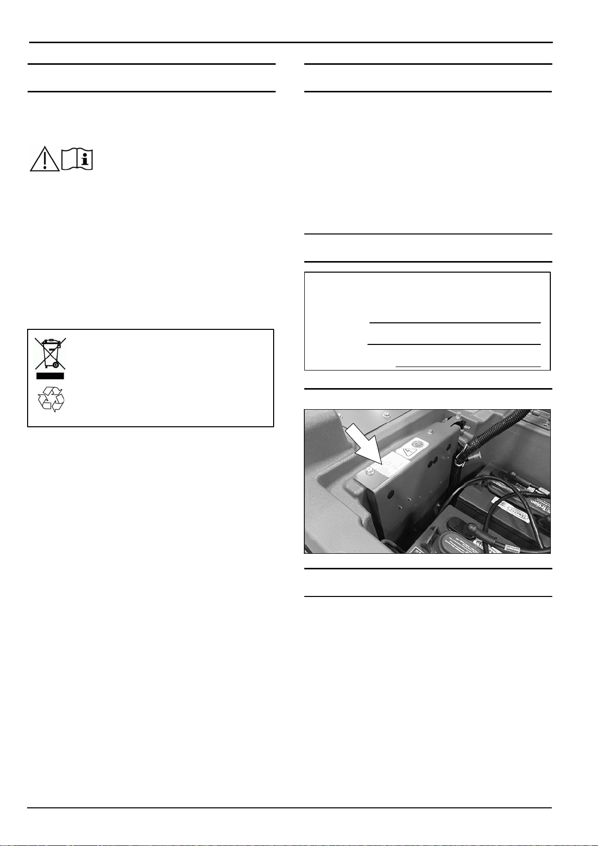
PROTECT THE ENVIRONMENT
Please dispose of packaging materials and
used machine components such as
batteries in an environmentally safe way
according to your local waste disposal
regulations.
The A500 walk-behind floor scrubber is intended for
commercial use, for example in hotels, schools,
hospitals, factories, shops, offices and rental
businesses. It is designed to scrub hard floor surfaces
(concrete, tile, stone, synthetic, etc.) in an indoor
environment. This machine is not intended for cleaning
carpets or sanding wood floors. Use only
recommended pads/brushes and commercially
available floor cleaning detergents. Do not use this
machine other than described in this Operator Manual.
MACHINE DATA
Please fill out at time of installation
for future reference.
Model No. -
Serial No. -
Installation Date -
SERIAL NUMBER LABEL LOCATION
Always remember to recycle.
Alfa, uma empresa Tennant
Rua Barão de Campinas, 715
CEP: 01201- 902 - São Paulo - SP
Tel.: (11) 3361- 6111
www.alfatennant.com.br
Specifications and parts are subject to change without notice.
Original Instructions. Copyright ©2017 Tennant Company.
All rights reserved.
UNCRATING MACHINE
Carefully check machine for signs of damage. Report
damages at once to carrier. Contact distributor or
Tennant for missing items.
To uncrate the machine, remove straps, wheel blocks
and shipping brackets. Using the supplied ramp
carefully back the machine off the pallet. Make sure
scrub head is in the raised position.
ATTENTION: Do not remove machine from pallet
without using ramp, machine damage may occur.
2
ALFA A500 (07-2017)
Page 3

CONTENTS
INTRODUCTION 2............................
INTENDED USE 2............................
MACHINE DATA 2............................
SERIAL NUMBER LABEL LOCATION 2......
UNCRATING MACHINE 2.....................
SAFETY
IMPORTANT SAFETY INSTRUCTIONS 5.......
SAFETY LABELS 7...........................
OPERATION
MACHINE COMPONENTS 8...................
MACHINE COMPONENTS 9...............
CONTROL PANEL COMPONENTS 9...........
MACHINE SYMBOLS 9.......................
INSTALLING BATTERIES 10...................
HOW THE MACHINE WORKS 10...............
BRUSH AND PAD INFORMATION 11............
MACHINE SETUP 11..........................
ATTACHING SQUEEGEE ASSEMBLY 11.....
INSTALLING DISK BRUSHES/PADS
(Disk Scrub Head Model) 12.................
FILLING SOLUTION TANK 13...............
ec-H2O WATER CONDITIONING CARTRIDGE
(ec-H2O MODEL) 13........................
CONTROL PANEL OPERATION 14.............
1-STEP BUTTON 14........................
BRUSH PRESSURE BUTTON 14............
SOLUTION FLOW BUTTON 14..............
ec-H2O INDICATOR (Option) 14.............
SERVICE INDICATOR 15...................
BATTERY DISCHARGE INDICATOR 15......
MACHINE OPERATION 15.....................
PRE-OPERATION CHECK LIST 15...........
OPERATING MACHINE 15..................
EMERGENCY SHUT-OFF BUTTON 16.......
WHILE OPERATING MACHINE 16...........
CIRCUIT BREAKER PANEL 17..............
HOUR METER 17..........................
DRAINING TANKS 17..........................
DRAINING RECOVERY TANK 17............
DRAINING SOLUTION TANK 18.............
SERVICE INDICATOR CODES 19...............
ec-H2O SYSTEM SERVICE INDICATO R CODES
- OPTION 20..............................
MAINTENANCE
MAINTENANCE CHART 21.....................
MACHINE MAINTENANCE 22..................
AFTER DAILY USE 22......................
AFTER WEEKLY USE 23...................
AFTER EVERY 50 HOURS OF USE 23.......
ELECTRIC MOTORS 24....................
BATTERIES 24................................
MAINTENANCE-FREE BATTERIES 24.......
FLOODED (WET) LEAD-ACID BATTERIES 24
CHECKING CONNECTIONS / CLEANING 25..
CHARGING BATTERIES 25.................
BATTERY CHARGER SETTINGS 26.........
SQUEEGEE BLADE REPLACEMENT 26.........
ec-H2O WATER CONDITIONING CARTRIDGE
REPLACEMENT 27............................
MACHINE JACKING 28........................
TRANSPORTING MACHINE 28.................
STORING MACHINE 29........................
FREEZE PROTECTION 29..................
TROUBLESHOOTING 30.......................
SPECIFICATIONS
GENERAL MACHINE
DIMENSIONS/CAPACITIES/PERFORMANCE 32.
MACHINE DIMENSIONS 33....................
ALFA A500 (07-2017)
3
Page 4

CONTENTS
4
ALFA A500 (07-2017)
Page 5

SAFETY
IMPORTANT SAFETY INSTRUCTIONS - SAVE THESE INSTRUCTIONS
The following warning precautions are used throughout
this manual as indicated in their description:
WARNING: To warn of hazards or unsafe
practices which could result in severe personal
injury or death.
FOR SAFETY: To identify actions which must be
followed for safe operation of equipment.
The following information signals potentially
dangerous conditions to the operator. Know when
these conditions can exist. Locate all safety devices on
the machine. Report machine damage or faulty
operation immediately.
WARNING: To Reduce the Risk of Fire,
Explosion, Electric Shock or Injury:
- Read manual before operating machine.
- Do not use or pick up flammable materials or
reactive metals.
- Do not use near flammable liquids, vapors or
combustible dusts.
This machine is not equipped with an
explosion proof motor. The electric motor will
spark upon start up and during operation
which could cause a flash fire or explosion if
machine is used in an area where flammable
vapors/liquids or combustible dusts are
present.
- Batteries emit hydrogen gas. Explosion or fire
can result. Keep sparks and open flame away
when charging.
- Disconnect battery cables and charger cord
before cleaning and servicing machine.
- Do not charge batteries with damaged cord. Do
not modify plug.
If the charger supply cord is damaged or
broken, it must be replaced by the
manufacturer or its service agent or a similarly
qualified person in order to avoid a hazard.
- Do not use outdoors. Store indoors.
- Spinning pad/brush, keep hands away.
FOR SAFETY:
1. Do not operate machine:
- Unless trained and authorized.
- Unless operator manual is read and
understood.
- Unless mentally and physically capable of
following machine instructions.
- Under the influence of alcohol or drugs.
- While using a cell phone or other types of
electronic devices.
- If not in proper operating condition.
- In outdoor areas. This machine is for
indoor use only.
- In areas where flammable vapors/liquids or
combustible dusts are present.
- With pads or accessories not supplied or
approved by Tennant. The use of other
pads may impair safety.
- In areas with possible falling objects.
- In areas that are too dark to safely see the
controls or operate machine.
2. Before operating machine:
- Check machine for fluid leaks.
- Make sure all safety devices are in place
and operate properly.
3. When operating machine:
- Use only as described in this manual.
- Report machine damage or faulty operation
immediately.
- Wear closed-toe, non-slip work shoes.
- Reduce speed when turning.
- Go slowly on inclines and slippery
surfaces.
- The machine may only be operated on
gradients up to 2%.
- Follow site safety guidelines concerning
wet floors.
- Follow mixing, handling and disposal
instructions on chemical containers.
- Do not carry passengers on machine.
- Use care when reversing machine.
- Keep children and unauthorized persons
away from machine.
- Do not allow machine to be used as a toy.
4. Before leaving or servicing machine:
- Stop on level surface.
- Set the parking brake, if equipped.
- Turn off machine and remove key.
5. When servicing machine:
- Disconnect battery connection and charger
cord before working on machine.
- All work must be done with sufficient
lighting and visibility.
- All repairs must be performed by trained
personnel.
- Use Tennant supplied or approved
replacement parts.
- Do not modify the machine from its original
design.
- Block machine tires before jacking machine
up.
- Jack machine up at designed locations
only. Support machine with jack stands.
- Use hoist or jack that will support the
weight of the machine.
- Avoid moving parts. Do not wear loose
clothing or jewelry and secure long hair.
ALFA A500 (07-2017)
5
Page 6

SAFETY
- Do not disconnect the off-board charger's
DC cord from the machine's receptacle
when the charger is operating. Arcing may
result. If the charger must be interrupted
during charging cycle, disconnect the AC
power supply cord first.
- Do not use incompatible battery chargers
as this may damage battery packs and
potentially cause a fire hazard.
- Inspect charger cord regularly for damage.
- Keep work area well ventilated.
- Avoid contact with battery acid.
- Keep all metal objects off batteries.
- Do not power spray or hose off machine.
Electrical malfunction may occur. Use
damp cloth.
- Use a hoist or adequate assistance when
lifting batteries.
- Battery installation must be done by trained
personnel.
- Only use distilled water when filling the
automatic battery watering tank.
- Wear personal protection equipment as
needed and where recommended in this
manual.
6. When loading/unloading machine onto/off
truck or trailer:
- Drain tanks before loading machine.
- Use a ramp that can support the machine
weight and operator.
- The machine may only be operated on
gradients up to 2%.
- Lower the scrub head and squeegee before
tying down machine.
- Turn machine off and remove key.
- Set parking brake (if equipped).
- Block machine wheels.
- Use tie-down straps to secure machine.
For Safety: wear protective gloves.
For Safety: wear eye protection.
6
ALFA A500 (07-2017)
Page 7
SAFETY
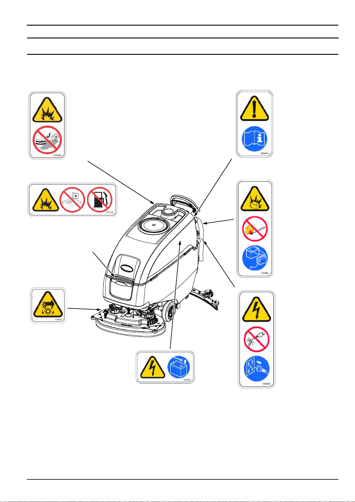
SAFETY LABELS
The safety labels appear on the machine in the locations indicated. Replace labels if they are missing or become
damaged or illegible.
WARNING LABEL Flammable
materials or
reactive metals can
cause an explosion
or fire. Do not pick
up.
Located near control
console.
WARNING LABEL Flammable
materials can cause
explosion or fire. Do
not use flammable
materials in tank(s).
Located on backside
of solution tank cover.
FOR SAFETY
LABEL - Read
manual before
operating
machine.
Located near
control console.
WARNING LABEL Batteries emit
hydrogen gas.
Explosion or fire
can result. Keep
sparks and open
flameawaywhen
charging.
Located near control
console and bottom
side of recovery tank.
WARNING LABEL Spinning brush.
Keep hands away.
Located on scrub
head.
WARNING LABEL Do not charge
batteries with
damaged cord.
Electric shock can
result. Disconnect
charger cord before
servicing.
Located near control
console.
WARNING LABEL - Electrical
Hazard. Disconnect battery
cables before servicing
machine.
Located on circuit board panel.
ALFA A500 (07-2017)
7
Page 8

OPERATION
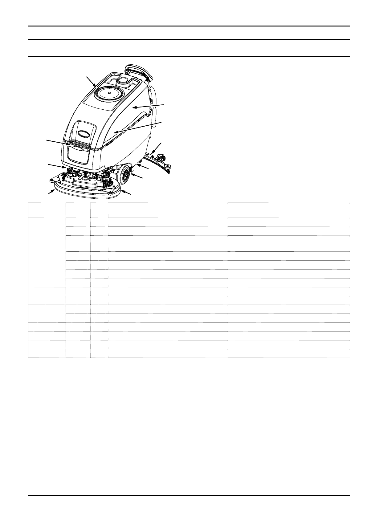
MACHINE COMPONENTS
20
21
25
23
13
10
22
14
3
4
30
7
28
8
2026
29
11
12
24
27
2
1
5
6
9
8
18
16
19
15
31
17
32
ALFA A500 (07-2017)
Page 9
MACHINE COMPONENTS
1. Control handle
2. Control handle start bail
3. Control panel
4. Forward/Reverse lever
5. Speed control knob
6. USB port (Service only)
7. Key switch
8. ec-H2O on/off switch (option)
9. Emergency shut-off button
10. Hour meter
11. Solution tank rear hose fill-port
12. Solution tank level/drain hose
13. Recovery tank drain hose
14. Circuit breaker panel
15. Off-board battery charger receptacle
16. Squeegee lower/lift foot pedal
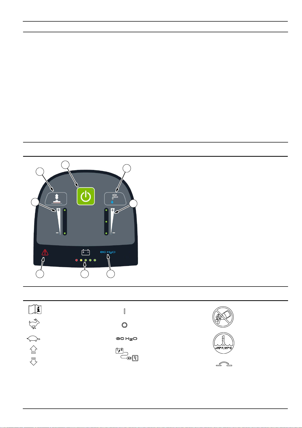
CONTROL PANEL COMPONENTS
OPERATION
17. Squeegee assembly
18. Squeegee vacuum hose
19. Squeegee debris/drip tray
20. Recovery tank
21. ec-H2O module (option)
22. ec-H2O water conditioning cartridge
23. Battery compartment
24. Solution tank
25. Solution tank front bucket fill-port
26. Scrub head
27. Scrub head skirt
28. Pad release plunger
29. Wall rollers
30. Transport tie-down bracket
31. Recovery tank lid
32. Recovery tank float shut-off screen
1
2
3
6 7 8
MACHINE SYMBOLS
1. 1-Step button
4
2. Brush pressure button
3. Brush pressure indicator
4. Solution flow button
5. Solution flow indicator
6. Service Indicator
7. Battery discharge indicator (BDI)
5
8. ec-H2O indicator (option)
Read Manual
Fast speed
Slow speed
Forward / Reverse
ALFA A500 (07-2017)
Key On
Key Off
ec-H2O scrubbing
(option)
Battery charge
No detergent
(ec-H2O option)
Water temperature
(ec-H2O option)
Circuit breaker
9
Page 10

OPERATION
INSTALLING BATTERIES
WARNING: Batteries emit hydrogen gas.
Explosion or fire can result. Keep sparks and open
flame away when charging.
FOR SAFETY: When servicing machine, wear
appropriate personal protection equipment as
needed. Avoid contact with battery acid.
3. Using the supplied battery post boots, connect the
cables to battery posts, RED TO POSITIVE (+) &
BLACK TO NEGATIVE (-) (Figure 3).
FOAM SPACER
BATTERY SPECIFICATIONS
Requires four 6 volt deep-cycle batteries, ≤ 260 Ah @
20 hr.
Contact distributor or Tennant for battery
recommendations.
FOR SAFETY: Before leaving or servicing machine,
stop on level surface, turn off machine, remove key
and set parking brake if equipped.
1. Lift the recovery tank to access the battery
compartment (Figure 1).
FIG. 1
2. Carefully install the batteries into the battery
compartment tray and arrange the battery posts as
shown (Figure 2). Position foam spacer between
batteries as shown.
FOR SAFETY: When servicing machine, use a
hoist or adequate assistance when lifting batteries.
RED
BLACK
FIG. 3
IMPORTANT: Before charging batteries, make sure
the battery charger and the machine's battery
discharge indicator are properly set for battery
type. Failure to properly set will result in battery
damage. See BATTERY CHARGER SETTINGS.
ATTENTION: Do not disconnect battery cables
while charger is plugged in, circuit board damage
may result.
HOW THE MACHINE WORKS
Conventional scrubbing:
When using the conventional scrubbing mode, water
and detergent mixture from the solution tank flows to
the floor and the rotating brush(es)/pad(s) scrub the
floor clean. As the machine moves forward, the
squeegee with vacuum suction picks up the dirty
solution from the floor into the recovery tank.
ec-H2O NanoClean Technology (option):
When using the ec-H2O NanoClean technology,
normal water passes through a module where it is
electrically converted into a cleaning solution. The
electrically converted water attacks the dirt, allowing
the machine to easily scrub away the suspended soil.
The converted water then returns to normal water in
the recovery tank.
10
FIG. 2
ALFA A500 (07-2017)
Page 11

OPERATION
BRUSH AND PAD INFORMATION
For best cleaning results use the appropriate brush or
pad for your cleaning application. Listed below are
brushes and pads and the applications for which each
is best suited.
NOTE: The amount and type of soilage play an
important role in determining the type of brush or pad
to use. Contact a Tennant representative for specific
recommendations.
Soft nylon bristle scrub brush (White) -
Recommended for cleaning coated floors without
removing finish. Cleans without scuffing.
Polypropylene bristle scrub brush (Black) -
This general purpose polypropylene bristle scrub brush
is used for scrubbing lightly compacted soilage. This
brush works well for maintaining concrete, wood and
grouted tile floors.
Super abrasive bristle scrub brush (Gray) -
Nylon fiber impregnated with abrasive grit to remove
stains and soilage. Strong action on any surface.
Performs well on buildup, grease, or tire marks.
Polishing pad (White) - Used to maintain highly
polished or burnished floors.
Buffing pad (Red) - Used for light duty scrubbing
without removing floor finish.
MACHINE SETUP
ATTACHING SQUEEGEE ASSEMBLY
FOR SAFETY: Before leaving or servicing machine,
stop on level surface, turn off machine, remove key
and set parking brake if equipped.
1. Lift the squeegee mount bracket to the raised
position. Place foot under pedal to lift (Figure 4).
FIG. 4
2. Mount the squeegee assembly to the squeegee
mount bracket (Figure 5). Tighten knobs to secure
squeegee assembly to bracket.
Scrubbing pad (Blue) - Used for medium to
heavy-duty scrubbing. Removes dirt, spills, and scuffs
and leaves surface clean ready for re-coating.
Stripping pad (Brown) - Used for stripping of floor
finish to prepare the floor for recoating.
Heavy duty stripping pad (Black) - Used for
aggressive stripping of heavy finishes/sealers, or very
heavy duty scrubbing.
Surface preparation pad (Maroon) - Used for very
aggressive chemical free removal of floor finish to
prepare the floor for re-coating.
Turf scrubbing pad (Green) - Used to scrub uneven
floor surfaces with crevices, cracks and deep grout
lines.
FIG. 5
3. Connect the vacuum hose to the squeegee
assembly (Figure 6).
ALFA A500 (07-2017)
FIG. 6
11
Page 12

OPERATION
5. Check the squeegee blades for proper deflection.
The blades should deflect as shown (Figure 7).
FIG. 7
6. To adjust the blade deflection, loosen the jam nut
and turn the caster hex plate until there is a 1/16”
(2mm) space between caster and floor. Re-tighten
jam nut and repeat step on other caster (Figure 8).
Jam Nut
1/16 in
2mm
FOR SAFETY: Do not operate machine with pads
or accessories not supplied or approved by
Tennant. The use of other pads may impair safety.
3. Set the yellow spring clips to the open position to
make brush installation easier. Press clips down
and outward to set (Figure 10).
FIG. 10
4. Align the pad driver or brush under the motor hub
and push it upward to engage hub (Figure 11).
Replace pads or brushes when they no longer
clean effectively or when the bristles on the brush
disk are worn to the yellow indicator (Figure 11).
Caster hex plate
FIG. 8
INSTALLING DISK BRUSHES/PADS
1. Raise scrub head off floor and remove key.
FOR SAFETY: Before leaving or servicing machine,
stop on level surface, turn off machine, remove key
and set parking brake if equipped.
2. Attach the pad to the pad driver before installing
the driver. Secure pad with center-lock (Figure 9).
FIG. 11
5. To remove the pad drivers/brushes, raise the scrub
head and press down on the yellow pad release
plunger (Figure 12). Pad will drop to floor.
12
FIG. 12
FIG. 9
ALFA A500 (07-2017)
Page 13

FILLING SOLUTION TANK
FOR SAFETY: Before leaving or servicing machine,
stop on level surface, turn off machine, remove key
and set parking brake if equipped.
The machine is equipped with two solution tank fill-port
locations. A front bucket fill-port and a rear hose fill-port
(Figure 13).
FIG. 13
1. Fill the solution tank with water until level reaches
the ”3/3” mark on the solution tank drain hose
indicator (Figure 14).
ec-H2O Scrubbing (Option)- Fill solution tank
with only cool clean water (less than 70°F/21°C).
Do not add conventional floor cleaning detergents.
An ec-H2O system fault will occur if cleaning
detergents are added.
Conventional Scrubbing - Fill solution tank with
water (not to exceed 60°C/140°F). Pour a
recommended cleaning detergent into the solution
tank according to mixing instructions on the
container.
ATTENTION: For Conventional Scrubbing, only use
commercially approved cleaning detergents. Machine
damage due to improper detergent usage will void the
manufacturer's warranty.
OPERATION
2. Replace the front and rear fill-port cover after filling
solution tank (Figure 15).
FIG. 15
ec-H2O WATER CONDITIONING CARTRIDGE
(ec-H2O MODEL)
The ec-H2O system is equipped with a water
conditioning cartridge (Figure 16). The cartridge is
designed to protect the machine's plumbing system
from potential scaling.
The cartridge is required to be replaced when it
reaches its maximum water usage or expiration time on
when the cartridge was activated, which ever comes
first.
Depending on machine usage a new cartridge can last
anywhere from 12 to 24 months.
WARNING: Flammable materials can cause an
explosion or fire. Do not use flammable materials
in tank(s).
NOTE: Do not use the ec-H2O system when there are
conventional cleaning detergents in the solution tank.
Drain, rinse, and refill the solution tank with clear cool
water before operating the ec-H2O system.
Conventional cleaning detergents will cause an ec-H2O
system fault.
FIG. 14
FIG. 16
The control panel will signal the following code when
it's time to replace the cartridge (Figure 17). The
ec-H2O icon will begin to blink blue and red. See
SERVICE INDICATOR CODES for further details.
FIG. 17
ALFA A500 (07-2017)
13
Page 14

OPERATION
All cartridges are labeled with a manufacture date. The
shelf-life of an un-installed cartridge is one year from
manufacture date. For new cartridge replacement, the
ec-H2O module timer must be reset. See ec-H2O
WATER CONDITIONING CARTRIDGE
REPLACEMENT.
ATTENTION: During first time use and after replacing
the water conditioning cartridge, the ec-H2O system
will automatically override the selected solution flow
rateforupto75minutes.
CONTROL PANEL OPERATION
1-STEP BUTTON
With key turned on, press the 1-STEP button to
activate the scrub function (Figure 18). The scrub head
will lower to floor. Press button again to stop the scrub
function and to raise scrub head.
SOLUTION FLOW BUTTON
Press the solution flow button to increase or decrease
the solution flow rate (Figure 20). The solution flow
indicator will display flow setting.
No LED = No flow, One LED = Low flow, two LED's =
Medium flow, three LED's = High flow.
FIG. 20
ec-H2O INDICATOR (Option)
The ec-H2O system automatically turns on at each key
start. A blue ec-H2O indicator will appear on the control
panel indicating that the system is activated. To turn off
the ec-H2O system, press the ec-H2O switch located
below the key switch. The blue ec-H2O indicator will
disappear (Figure 21).
FIG. 18
BRUSH PRESSURE BUTTON
Press the brush pressure button to increase or
decrease the brush pressure (Figure 19). The brush
pressure indicator will display the pressure setting. One
LED = Low pressure, two LED's = High pressure.
FIG. 19
NOTE: Orbital scrub head model - If brush pressure is
set too high for scrubbing conditions, the brush
pressure setting will automatically reduce to a lower
setting and begin flashing. The flashing LED alerts the
operator to reduce the brush pressure setting to
prevent brush motor overload.
FIG. 21
ec-H2O INDICATOR CONDITION
Solid blue Normal operation
Blinking blue/red Water conditioning cartridge
expired. Replace cartridge.
Solid or blinking red A system fault has occurred.
See Service Indicator Codes.
NOTE: If a fault occurs to the ec-H2O system, the
machine will automatically turn off the ec-H2O system
and convert over to conventional scrubbing. The
service indicator icon will remain solid red or continue
to blink red until the ec-H2O fault is serviced.
14
ALFA A500 (07-2017)
Page 15

OPERATION
SERVICE INDICATOR
When the machine or on-board battery charger detects
a fault, the service indicator will light up and begin
flashing (Figure 22). The battery discharge indicator
lights will also flash a fault code. See SERVICE
INDICATOR CODES to diagnose machine fault.
FIG. 22
BATTERY DISCHARGE INDICATOR
The battery discharge indicator (BDI) displays the
charge level of the batteries while the machine is
operating. When the batteries are fully charged, all five
indicators are lit (Figure 23). When the discharge level
reaches the red light, stop scrubbing and recharge the
batteries. When the red light begins to flash, the scrub
function will be disabled to protect the batteries from
total discharge. The machine will still propel when the
red light is flashing. This will allow user to transport the
machine to the charging station.
ec-H2O Scrubbing: Confirm solution tank is filled
with clear cool water only.
ec-H2O Scrubbing: Confirm all conventional
cleaning agents/restorers are drained and rinsed
from solution tank.
Check machine for proper operation.
OPERATING MACHINE
For control panel operating instructions, see
CONTROL PANEL OPERATION.
1. Turn the key to the on ( I ) position (Figure 24).
FIG. 24
2. ec-H2O models - The ec-H2O system will
automatically turn on at key start up. The ec-H2O
indicator will appear on the control panel indicating
that the system is activated (Figure 25).
ATTENTION: When conventional scrubbing with
cleaning detergents in solution tank, make sure to turn
off the ec-H2O system by pressing the ec-H2O switch
(Figure 25). If cleaning detergent is accidentally cycled
through ec-H2O system, a system fault will occur. To
clear fault, drain solution tank, add clear water and
operate the ec-H2O system to clear fault. If fault
repeats, continue to recycle key until fault clears. See
SERVICE INDICATOR CODES for further detail.
FIG. 23
MACHINE OPERATION
FOR SAFETY: Do not operate machine unless
operator manual is read and understood.
PRE-OPERATION CHECK LIST
Sweep area and remove any obstructions.
Check brushes/pads for wear and damage.
Check squeegee blades for wear and damage.
Confirm recovery tank is empty, debris tray is clean
and the float shut-off screen is installed and clean.
Check scrub head skirt for wear and damage.
ALFA A500 (07-2017)
FIG. 25
3. Lower the squeegee assembly to floor by stepping
on foot pedal (Figure 26). To raise squeegee
assembly, place foot under foot pedal and lift. The
vacuum motor will automatically start when
squeegee is lowered to floor.
15
Page 16

OPERATION
FIG. 26
4. Press the 1-STEP button to activate the scrub
function (Figure 27). The scrub head will lower to
floor.
7. Adjust the scrubbing speed by turning the speed
dial to the desired speed (Figure 30).
FIG. 30
8. To stop scrubbing, release the start bail, press the
1-STEP button and raise the squeegee assembly
off floor. Turn key off and set parking brake, if
equipped.
NOTE: To pick up any remaining water left on floor
after scrub head is raised continue to drive machine
forward with squeegee down.
FIG. 27
5. Push the directional lever forward to go forward
(Figure 28). Pull the lever back to maneuver
machine in reverse. Lift squeegee assembly when
backing machine.
FIG. 28
6. To begin scrubbing, pull the start bail (Figure 29).
EMERGENCY SHUT-OFF BUTTON
Push the emergency shut-off button in the event of an
emergency (Figure 31). This red button shuts off all
power to machine. To regain power, turn the button
clockwise and restart the key.
FIG. 31
WHILE OPERATING MACHINE
WARNING: Flammable materials or reactive
metals can cause an explosion or fire. Do not pick
up.
1. Overlap each scrub path by 2 inches/5 cm.
2. Keep machine moving to prevent damage to floor
finish.
3. Wipe squeegee blades with a cloth if blades leave
streaks.
4. Avoid bumping the machine into posts and walls.
5. When draining and refilling machine, always top off
the optional Severe Environment tank with
detergent.
16
FIG. 29
ALFA A500 (07-2017)
Page 17

FOR SAFETY: When operating machine, the
machine may only be operated on gradients up to
2%.
6. Pour a recommended foam control solution into the
recovery tank if excessive foam appears.
ATTENTION: Foam buildup will not activate the
float shut-off screen, vacuum motor damage will
result.
7. Use the double scrubbing method for heavily soiled
areas. First scrub the area with the squeegee up,
let solution set for 3-5 minutes, then scrub the area
a second time with squeegee down.
8. When leaving the machine unattended, park on
level surface, turn machine off, remove key and set
the parking brake, if equipped.
9. Do not operate machine in areas where the
ambient temperature is above 110ºF/43ºC or below
freezing 36ºF/2ºC.
OPERATION
HOUR METER
The hour meter records the number of hours the
machine has been operated. Use the hour meter to
perform specific maintenance procedures and to record
service history (Figure 33).
FIG. 33
CIRCUIT BREAKER PANEL
The machine is equipped with resettable circuit
breakers to protect the machine from a current
overload (Figure 32). If a circuit breaker trips,
disconnect the battery cable connection and reset the
breaker by pressing the reset button after the breaker
has cooled down. Reconnect the battery cable
connection. If the circuit breaker does not reset or
continues to trip contact service personnel.
FIG. 32
Circuit
Breaker
CB1 4A
CB2 10 A
Rating Circuit protected
Key switch, circuit
ec-H2O system, automatic
battery watering system
CB3 10 A
CB4 20 A
CB5 25 A
CB6 25 A
CB7 60 A
Scrub head lift actuator
Vacuum motor
Left brush motor
Right brush motor
Propel
DRAINING TANKS
FOR SAFETY: Before leaving or servicing machine,
stop on level surface, turn off machine, remove key
and set parking brake if equipped.
DRAINING RECOVERY TANK
Drain and clean the recovery tank after each use.
1. Transport the machine to drain area.
2. For models equipped with drain hose caps, hold
the hose upward, remove cap then slowly lower
hose to drain. For models equipped with flow
control valve drain hose, lower hose and slowly
open valve to drain (Figure 34).
FOR SAFETY: When servicing machine, all repairs
must be performed by trained personnel.
ALFA A500 (07-2017)
FIG. 34
NOTE: When using a bucket to drain the machine, do
not use the same bucket to fill the solution tank.
17
Page 18

OPERATION
3. Remove and clean the float shut-off screen (Figure
35).
FIG. 35
4. Rinse out the recovery tank with clean water and
wipe clean of any soil residue (Figure 36).
3. Rinse solution tank with clean water (Figure 38).
FIG. 38
4. Remove the solution tank filter and clean screen
after every 50 hours of use (Figure 39). Solution
filter is located under machine at rear. Drain
solution tank before removing filter.
FIG. 36
DRAINING SOLUTION TANK
Drain the solution tank daily.
1. Transport the machine to drain area.
FOR SAFETY: Before leaving or servicing machine,
stop on level surface, turn off machine, remove key
and set parking brake if equipped.
2. To drain remaining water from solution tank, pull
the solution tank level hose from the accessory rail
(Figure 37). Firmly reconnect the hose to the
accessory rail after draining tank.
FIG. 39
18
FIG. 37
ALFA A500 (07-2017)
Page 19

OPERATION
SERVICE INDICATOR CODES
When the machine or battery charger detects a fault, the service indicator will flash. A fault code will be provided to
determine problem as described below.
Flashing service
indicator
LED Fault Code
☼= Flashing
☼☼☼☼☼
S ☼☼ S ☼
S ☼ SS☼
S ☼ S ☼☼
SS☼ SS
SS☼ S ☼
SS☼☼S
SS☼☼☼
☼ SSS☼
☼ SS☼☼
☼ S ☼ S ☼
S ☼☼☼ S
Flashing LED
fault code
CAUSE SOLUTION
Emergency shut-off button activated Release emergency shut-off button and restart
machine
Head lift actuator relay wiring problem Check connections. Contact service.
Solution valve wiring, connector or control
board problem
Solution valve over current. Contact service
Brush motor relay wiring, connector or control
board problem
Head lift actuator relay wiring, connector or
control board problem
Propel circuit breaker tripped Reset circuit breaker. If fault repeats, contact
Propel motor wiring, connector or control board
problem
Propel faults Restart machine. If fault repeats, contact ser-
Brush motor relay short fault Check pad for floor type. If fault repeats
Start bail is pulled or obstructed before turning
machine on.
Scrub control board communication fault
ec-H2O system communication fault
Check connections. Contact service
Contact service
Contact service
service.
Contact service
vice.
contact service.
Release start bail or remove bail obstruction
before turning machine on.
Restart. If fault repeats, contact service.
ALFA A500 (07-2017)
19
Page 20

OPERATION
ec-H2O SYSTEM SERVICE INDICATOR CODES - OPTION
Solid or
blinking Red
ec-H2O
indicator
Contact service
Reset circuit breaker. If trip repeats, contact
service.
Flashing
service
indicator
LED Fault Code
☼= Flashing
S ☼ S ☼ S
S ☼☼☼☼
☼ S ☼ SS
ecH2O indicator
solid red
ecH2O indicator
blinking red
ecH2O indicator
blinking blue/red
*
Flashing
LED fault
code
CAUSE SOLUTION
ec-H2O pump wiring, connector or control
board problem.
ec-H2O pump over current Contact service
ec-H2O system breaker tripped
ec-H2O pump breaker tripped
ec-H2O electrical fault Contact service
ec-H2O system water and plumbing fault Contact service
Water system conditioning cartridge expired Replace water conditioning cartridge.
*Verify if cleaning detergent was added to solution tank. If ec-H2O system was operated with cleaning detergent,
drain solution tank, add clear water and operate the ec-H2O system until the fault code clears. If fault repeats,
continue to recycle key until fault clears.
20
ALFA A500 (07-2017)
Page 21
MAINTENANCE CHART
2
MAINTENANCE
8
5
3
4
10
7
9
6
Interval
Daily
1
Person
Resp.
Key Description Procedure
O 1 Pads Check, flip or replace
O 1 Brushes Check, clean
O 2 Recovery tank Drain, rinse, clean float shut-off screen
and debris tray
O 3 Solution tank Drain, rinse
O 4 Squeegee Clean, check for damage and wear
O 5 Batteries Charge if necessary
O 6 Scrub head skirt Check for damage and wear
Weekly
O 5 Battery cells Check electrolyte level
O 4 Squeegee assembly drip trap reservoir Check, clean
50 Hours
O 2 Recovery tank lid seal Check for wear.
O 7 Solution tank filter Remove and clean
200 Hours O 5 Batteries, terminals and cables Check and clean
750 Hours T 8 Vacuum motor Replace carbon brushes
1250 Hours T 9 Propel motor Replace carbon brushes
T 10 Brush motor Replace carbon brushes
O = Operator T = Trained Personnel
ALFA A500 (07-2017)
21
Page 22

MAINTENANCE
MACHINE MAINTENANCE
To keep the machine in good working condition, simply
perform the following maintenance procedures.
FOR SAFETY: Before leaving or servicing machine,
stop on level surface, turn off machine, remove key
and set parking brake if equipped.
FOR SAFETY: When servicing machine wear
personal protection equipment as needed. All
repairs must be performed by trained personnel
4. Disk scrub head - Turn pad over or replace when
worn (Figure 43).
AFTER DAILY USE
1. Drain and rinse out the recovery tank (Figure 40).
See DRAINING TANKS.
FIG. 40
2. Remove and clean the float shut-off screen (Figure
41).
FIG. 43
5. Replace brushes when they no longer clean
effectively or when the bristles are worn to the
yellow indicator (Figure 44).
FIG. 44
6. Wipe the squeegee blades clean. Inspect blades
for wear and damage (Figure 45). Rotate blade if
worn. See SQUEEGEE BLADE REPLACEMENT.
FIG. 41
3. Drain and rinse out the solution tank (Figure 42).
FIG. 42
22
FIG. 45
ALFA A500 (07-2017)
Page 23

7. Clean scrub head skirt. Check for wear or damage
(Figure 46). Replace if worn or damaged.
FIG. 46
8. Clean the outside surface of the machine with an
all purpose cleaner and damp cloth (Figure 47).
MAINTENANCE
AFTER WEEKLY USE
1. Check the electrolyte level in all batteries (Figure
49). See BATTERIES.
NOTE: If machine is equipped with the automatic or
manual battery watering system, See BATTERIES.
FOR SAFETY: When servicing machine, do not
power spray or hose off machine. Electrical
malfunction may occur. Use damp cloth.
FIG. 47
9. Charge batteries (Figure 48). See BATTERIES.
FIG. 49
2. Remove the drip trap cover from the squeegee
assembly and clean reservoir (Figure 50).
FIG. 50
AFTER EVERY 50 HOURS OF USE
Drain solution tank. Remove the solution tank filter and
clean screen (Figure 51). Turn the filter bowl
counter-clockwise to remove.
FIG. 48
ATTENTION: Do not disconnect battery cables
while charger is plugged in, circuit board damage
may result.
ALFA A500 (07-2017)
FIG. 51
23
Page 24

MAINTENANCE
ELECTRIC MOTORS
Replace motor carbon brushes as indicated. Contact
trained personnel for carbon brush replacement.
Carbon Brush Replacement Hours
Vacuum motor 750
Propel motor 1250
Disk brush motors 1250
BATTERIES
FOR SAFETY: Before servicing machine, stop on
level surface, turn off machine, remove key and set
parking brake if equipped.
The lifetime of the batteries depends on their proper
maintenance. To get the most life from the batteries;
S Do not charge the batteries more than once a day
and only after running the machine for a minimum of
15 minutes.
S Do not leave the batteries partially discharged for
long period of time.
FLOODED (WET) LEAD-ACID BATTERIES
The flooded (wet) lead-acid batteries require routine
watering as described below. Check the battery
electrolyte level weekly.
NOTE: If machine is equipped with the automatic or
manual battery watering system, proceed to the
BATTERY WATERING SYSYEM instructions.
The electrolyte level should be slightly above the
battery plates as shown before charging (Figure 52).
Add distilled water if low. DO NOT OVERFILL. The
electrolyte will expand and may overflow when
charging. After charging, distilled water can be added
up to about 3 mm (0.12 in) below the sight tubes.
Before Charging After Charging
S Only charge the batteries in a well-ventilated area to
prevent gas build up. Charge batteries in areas with
ambient temperatures 80ºF/27ºC or less.
S Allow the charger to complete charging the batteries
before re-using the machine.
S Maintain the proper electrolyte levels of flooded (wet)
batteries by checking levels weekly.
Your machine is equipped with either flooded (wet)
lead-acid or maintenance-free (Sealed AGM) batteries
supplied by Tennant.
FOR SAFETY: When servicing machine, keep all
metal objects off batteries. Avoid contact with
battery acid.
MAINTENANCE-FREE BATTERIES
Maintenance-free (Sealed AGM) batteries do not
require watering. Cleaning and other routine
maintenance is still required.
FIG. 52
NOTE: Make sure the battery caps are in place while
charging. There may be a sulfur smell after charging
batteries. This is normal.
CHECKING CONNECTIONS / CLEANING
After every 200 hours of use, check for loose battery
connections and clean the surface of the batteries,
including terminals and cable clamps to prevent battery
corrosion. Use a scrub brush with a strong mixture of
baking soda and water (Figure 53). Do not remove
battery caps when cleaning batteries.
24
FIG. 53
ALFA A500 (07-2017)
Page 25

CHARGING BATTERIES
The charging instructions in this manual are intended
for the battery charger supplied with your machine. The
use of other battery chargers that are not supplied and
approved by Tennant are prohibited.
If your machine is equipped with an off-board battery
charger refer to the charger's owners manual for
operating instructions. Contact distributor or Tennant
for battery charger recommendations if machine is not
equipped with charger.
FOR SAFETY: The use of incompatible battery
chargers may damage battery packs and
potentially cause a fire hazard.
IMPORTANT NOTICE: The battery charger is set to
charge the battery type supplied with your machine. If
you choose to change to a different battery type or
capacity (i.e. flooded (wet) lead-acid,
maintenance-free, sealed, AGM batteries, etc.), the
charger's charging profile must be changed to prevent
battery damage. See BATTERY CHARGER
SETTINGS.
1. Transport the machine to a well-ventilated area.
WARNING: Batteries emit hydrogen gas.
Explosion or fire can result. Keep sparks and open
flame away when charging.
2. Park the machine on a flat, dry surface, turn off
machine and remove key.
FOR SAFETY: When servicing batteries, stop on
level surface, turn off machine, remove key and set
parking brake if equipped.
3. If the machine is equipped with flooded (wet) lead-
acid batteries check the battery electrolyte level
weekly before charging.
MAINTENANCE
4. For models equipped with off-board chargers, first
connect the charger's DC cord into the machine's
battery charge receptacle then plug the AC power
supply cord into a properly grounded wall outlet
(Figure 54). Refer to the off-board battery charger's
owner manual for operating instructions.
FOR SAFETY: Do not disconnect the off-board
charger's DC cord from the machine's receptacle
when the charger is operating. Arcing may result. If
the charger must be interrupted during charging,
disconnect the AC power supply cord first.
FIG. 54
5. The charger will automatically begin charging and
and shut off when fully charged. The maximum
charging cycle may take up to 6-12 hours
depending on battery type.
ATTENTION: Do not disconnect battery cables
while charger is plugged in, circuit board damage
may result.
6. For models equipped with an off-board charger,
always disconnect the AC power supply cord first
before disconnecting charger from machine (Figure
55).
ALFA A500 (07-2017)
FIG. 55
25
Page 26
MAINTENANCE
OFF-BOARD BATTERY CHARGER SETTINGS
The off-board battery charger is set to charge the
battery type supplied with your machine. If you choose
to change to a different battery type or capacity, the
charger's charging profile must be changed to prevent
battery damage.
The machine's battery discharge indicator (BDI) must
also be reprogrammed to match battery type to prevent
battery damage and/or short run-time.
To change the off-board battery charger settings, refer
to the off-board charger's owner manual.
To reprogram the machine's battery discharge indicator
(BDI), service application software is required, contact
service.
SQUEEGEE BLADE REPLACEMENT
FOR SAFETY: Before leaving or servicing machine,
stop on level surface, turn off machine, remove key
and set parking brake if equipped.
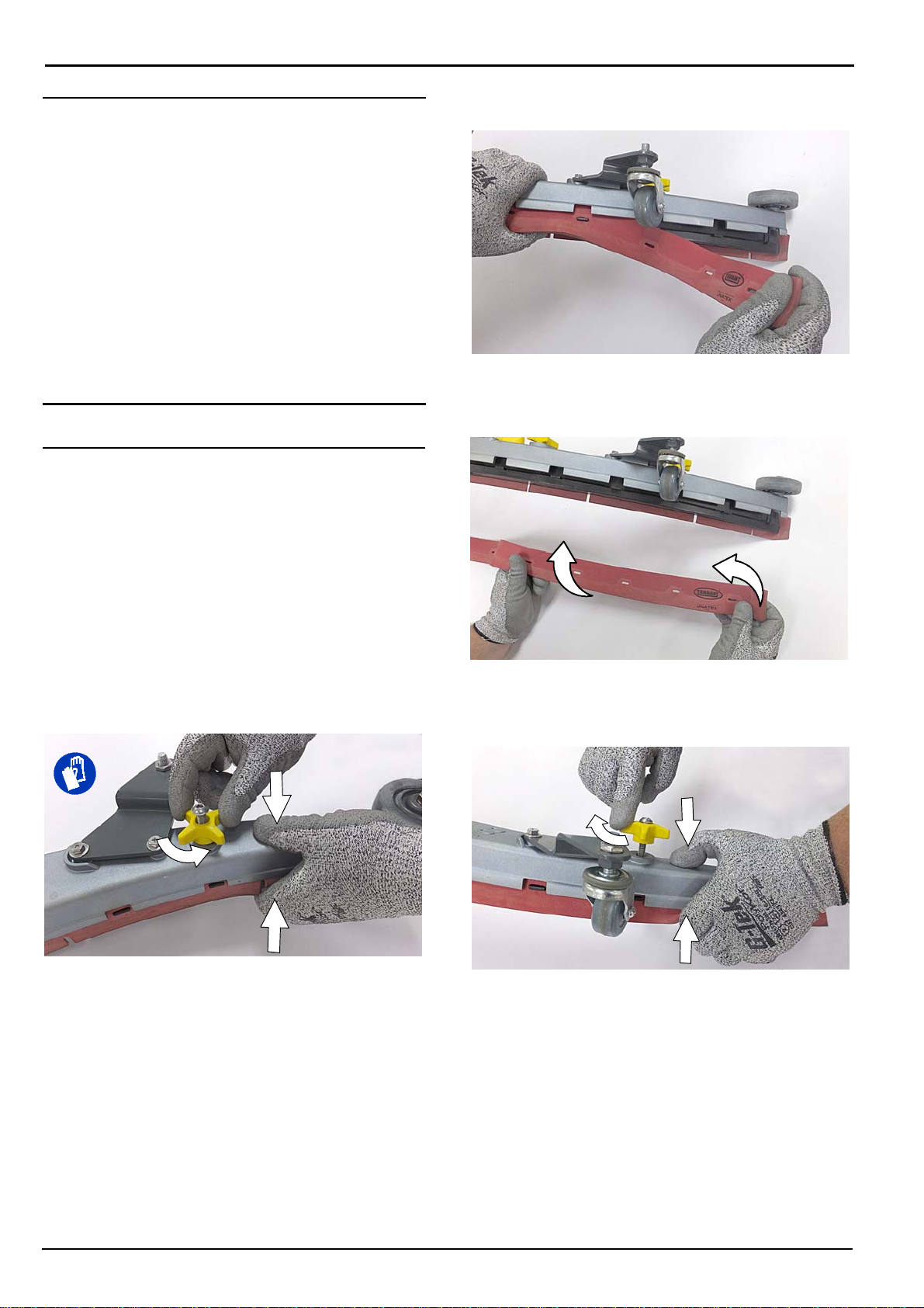
Each squeegee blade has four wiping edges. When the
blades become worn, simply rotate the blades
end-for-end or top-to-bottom for a new wiping edge.
Replace blade if all four edges are worn.
1. Remove the squeegee assembly from the
machine.
2. Fully loosen the two outside knobs on squeegee
assembly. This will separate the spring loaded
blade retainer from squeegee frame (Figure 56). To
loosen the knobs quickly, squeeze the blade
retainer and squeegee frame together.
3. Remove worn blade(s) from the blade retainer
(Figure 57).
FIG. 57
4. Rotate the rear blade to a new wiping edge and
reinstall blade (Figure 58). Make sure to align the
slots in the blade with retainer tabs.
FIG. 58
5. Squeeze the squeegee frame and blade retainer
together and re-tighten the two outside knobs
(Figure 59).
26
FIG. 56
FIG. 59
ALFA A500 (07-2017)
Page 27

ec-H2O WATER CONDITIONING
CARTRIDGE REPLACEMENT
FOR SAFETY: Before leaving or servicing machine,
stop on level surface, turn off machine, remove key
and set parking brake if equipped.
The water conditioning cartridge is required to be
replaced when it reaches its maximum water usage or
expiration time of when the cartridge was activated,
which ever comes first. The control panel will signal a
code when it's time to replace cartridge. See ec-H2O
WATER CONDITIONING CARTRIDGE for further
details.
Depending on machine usage, on average, a new
cartridge can last anywhere from 12 months for heavy
machine usage to 24 months for light machine usage.
ATTENTION: During first time use and after replacing
the water conditioning cartridge, the ec-H2O system
will automatically override the selected solution flow
rateforupto75minutes.
1. Park the machine on a level surface, remove the
key and set parking brake, if equipped.
2. Lift the recovery tank to access the ec-H2O water
conditioning cartridge (Figure 60). Drain recovery
tank before lifting tank.
MAINTENANCE
4. Fill in the installation date on the new cartridge
label (Figure 62).
FIG. 62
5. Install the new cartridge and reconnect the two
hoses. Make sure the hose connectors are fully
inserted into the cartridge.
6. Reset timer for new cartridge.
Carefully read and understand all steps first before
performing procedure.
a. Turn key on.
b. Press and hold the service switch, located on
the ec-H2O module, for 10 seconds
releasing service switch, the three solution flow
indicator lights will begin to (ripple) move back
and forth (Figure 63).
c. Within 5 seconds
after releasing the service
switch, while the three indicator lights are
moving back and forth, quickly
release the solution flow button located on
ec-H2O module (Figure 63).
The three indicator lights will then blink
to indicate timer has been reset.
times
Repeat process if the three indicator lights do
not blink three times.
. After
press and
three
FIG. 60
3. Disconnect the two hose connectors from the top
of the cartridge by pressing the gray collars inward
and pulling the connectors outward (Figure 61). Lift
cartridge to remove.
Gray
Collar
FIG. 61
Service switch
3 indicator lights
Solution flow button
FIG. 63
ALFA A500 (07-2017)
27
Page 28

MAINTENANCE
MACHINE JACKING
FOR SAFETY: Before leaving or servicing machine,
stop on level surface, turn off machine, remove key
and set parking brake if equipped.
Use the designated locations to jack up the machine for
service (Figure 64). Empty the recovery and solution
tanks and position the machine on a level surface
before jacking.
FOR SAFETY: When servicing machine, jack
machine up at designated locations only. Support
machine with jack stands. Use jack or hoist that
will support the weight of the machine.
FIG. 64
TRANSPORTING MACHINE
When transporting the machine by use of trailer or
truck, carefully follow loading and tie-down procedure:
1. Drain tanks, raise the scrub head and the remove
squeegee assembly.
2. Carefully load machine in trailer or on truck.
FOR SAFETY: When loading/unloading, use a
ramp that can support the machine weight and
operator.
FOR SAFETY: When loading/unloading, the
machine may only be operated on gradients up to
2%.
3. Once loaded, position the front of the machine up
against the front of the trailer or truck. Lower the
scrub head, turn key off and set parking brake, if
equipped.
4. Place a block behind each wheel (Figure 65).
5. Using tie-down straps, secure the machine using
the four tie-down brackets located on the machine
frame (Figure 65). It may be necessary to install
tie-down brackets to the floor of your trailer or
truck.
NOTE: When transporting machine in an open truck or
trailer, secure recovery tank lid.
ATTENTION: Do not use control console area
or accessory storage rails for tie-down
locations, damage may occur.
28
FIG. 65
ALFA A500 (07-2017)
Page 29

STORING MACHINE
The following steps should be taken when storing the
machine for extended periods of time.
1. Charge the batteries before storing machine to
prolong the life of the batteries. Recharge batteries
once a month.
2. Disconnect batteries before storing.
3. Drain and rinse recovery tank and solution tank.
4. Store the machine in a dry area with squeegee and
scrub head in the up position.
ATTENTION: Do not expose machine to rain, store
indoors.
5. Open the recovery tank lid to promote air
circulation.
6. If storing machine machine in freezing
temperatures, proceed to FREEZE PROTECTION.
MAINTENANCE
5. After storing machine in freezing temperatures,
drain any remaining antifreeze from the solution
tank. Add clean water to solution tank and to
optional detergent tank and operate the machine to
flush system.
6. Refill the automatic battery watering tank with
distilled water, if equipped.
NOTE: To prevent potential machine damage store
machine in a rodent and insect free environment.
FREEZE PROTECTION
Storing machine in freezing temperatures.
1. Completely drain solution tank and recovery tank.
2. Empty the water from the solution tank filter located
under machine. Replace filter (Figure 66).
FIG. 66
3. Pour 1 gallon / 4 liters of propylene glycol based
recreational vehicle (RV) antifreeze into the
solution tank.
4. Models not equipped with ec-H2O system machine on and operate the solution flow system.
Turn the machine off when the antifreeze is visible
on the floor.
Models equipped with ec-H2O system
machine and set the solution flow rate on and
operate ec-H2O scrubbing to cycle antifreeze
through system. Turn machine off when antifreeze
is visible on the floor. This may take up to two
minutes.
ALFA A500 (07-2017)
-Turn
Turn
29
Page 30

MAINTENANCE
TROUBLESHOOTING
PROBLEM CAUSE SOLUTION
Service indicator icon is
flashing
ec-H2O icon is red or
flashing red
ec-H2O icon is flashing
blue/red
Machine will not operate Emergency shut-off button activated Turn button to reset
On-board battery charger
will not operate
Machine will not propel Propel fault has been detected See SERVICE INDICATOR CODES
Brush motor will not
operate
Vacuum motor will not
operate
Poor scrubbing
performance
Machine or on-board battery charger
fault has been detected
ec-H2O system fault has been
detected
ec-H2O water conditioning cartridge
expired
Machine fault detected See SERVICE INDICATOR CODES
Batteries discharged Recharge batteries
Loose battery cable(s) Tighten loose cables
Faulty battery(s) Replace battery(s)
Faulty key switch Contact service
Faulty start bail switch Contact service
Circuit breaker tripped Reset circuit breaker
Faulty control board Contact service
Plug not connected to power supply Check plug connection
Batteries over discharged Replace batteries
Battery charger fault detected See SERVICE INDICATOR CODES
Faulty charger Replace charger
Faulty power supply cord Replace power supply cord
Circuit breaker tripped Reset circuit breaker
Faulty propel motor or wiring Contact service
Worn carbon brushes in motor Contact service
Brush motor fault has been detected. See SERVICE INDICATOR CODES
Faulty pad motor or wiring Contact service
Circuit breaker tripped Reset circuit breaker
Worn carbon brushes in motor Contact service
Broken or loose belt (cylindrical brush
model)
Squeegee assembly is raised off floor Lower squeegee assembly to floor
Vacuum motor fault has been
detected
Faulty vacuum motor or wiring Contact service
Circuit breaker tripped Reset circuit breaker
Debris caught in brush/pad Remove debris
Worn brush/pad Replace brush/pad
Incorrect brush pressure Adjust brush pressure
Wrong brush/pad type Use correct brush/pad for application
Low battery charge Recharge batteries
Uneven brush pressure Scrub head/brushes not level. Contact service
See SERVICE INDICATOR CODES
See SERVICE INDICATOR CODES
Replace water conditioning cartridge.
Contact service
See SERVICE INDICATOR CODES
30
ALFA A500 (07-2017)
Page 31

TROUBLESHOOTING - Continued
PROBLEM CAUSE SOLUTION
Trailing water - poor or
no water pickup
Little or no solution flow Empty solution tank Refill solution tank
Automatic battery
watering tank does not
dispense water
Short run time Low battery charge Charge batteries
Full recovery tank or excessive foam
buildup
Loose drain hose cap or flow control
valve is open
Worn squeegee blades Rotate or replace squeegee blades
Clogged drip trap (Squeegee
assembly)
Clogged squeegee assembly Clean squeegee assembly
Loose vacuum hose connection Secure vacuum hose connection
Clogged vacuum hose Flush vacuum hose
Damaged vacuum hose Replace vacuum hose
Clogged float shut-off screen in
recovery tank
Recovery tank lid not completely
closed
Defective seals on recovery tank lid Replaced seal
Low solution flow rate set Increase solution flow rate
Clogged solution tank filter Clean filter
Plugged solution supply line Flush solution supply line
Tank is empty Refill tank
Faulty float switch Contact service
Defective pump Contact service
Pump not priming Contact service
Faulty control board Contact service
Batteries need maintenance See BATTERIES
Defective battery or end of battery life Replace batteries
Battery discharge indicator (BDI)
programmed incorrectly
Faulty charger Replace battery charger
Brush pressure set too high Lower brush pressure
Drain recovery tank
Replace cap or close flow control valve on
drain hose
Remove cover and clean
Clean screen
Check lid for obstructions
See CHARGING BATTERIES
MAINTENANCE
ALFA A500 (07-2017)
31
Page 32

SPECIFICATIONS
GENERAL MACHINE DIMENSIONS/CAPACITIES/PERFORMANCE
MODEL 32 in / 800 mm Dual Disk
Length 61.1 in / 1552 mm
Width 33.5 in / 850 mm
Height 43.3 in / 1100 mm
Weight 355 Ib / 161 kg
Weight (with batteries) 645 Ib / 293 kg
GVW 835 Ib / 379 kg
Squeegee width (Std) 41.3 in / 1049 mm
Squeegee width (Option) 46.6 in / 1234 mm
Solution tank capacity 22.5 gal / 85 L
Recovery tank capacity 27 gal / 102 L
Scrubbing path width 32 in / 800 mm
Down pressure Low: -75 lbs / 34 kg,
Scrubbing speed 2.5 mph / 4.0 km/h (220 fpm / 67 mpm)
Transport speed 2.7 mph / 4.4 km/h (240 fpm / 73 mpm)
Reverse speed 11.6 mph / 2.6 km/h (144 fpm / 44 mpm)
Productivity rate - estimated actual 25,714 ft2/hr / 2389 m2/hr
ec-H2O productivity rate - est. actual 27,323 ft2/hr / 2538 m2/hr
Aisle turnaround width 61.6 in / 1565 mm
Maximum operating gradient 2%
Solution flow rate Low: .30 gpm / 1.1 L/min, Med: .40 gpm / 1.5 L/min, High: .50 gpm / 1.9 L/min
ec-H2O solution flow rate Low: .22 gpm / 0.84 L/min,
Brush motor 2-24 VDC, 0.75 hp/0.55 kW, 29 A, 220 rpm
Propel motor 24 VDC, 0.63 hp / 0.48 kW, 20A
Vacuum motor 24 VDC, 0.46 hp / .34 kW, 14.3 A
Water lift 34 in / 864 mm
ec-H2O solution pump 24 VDC, 2 A, 1.0 gpm / 3.8 L/min, min open flow
Machine voltage 24 VDC
Battery capacity 4-6V 210AH C/20 Wet, 4-6V 225AH C/20 Wet
Total power consumption 66 A nominal / 1.6 kW
Battery Charger - smart off-board 85-265VAC, 50/60Hz, 24VDC, 25A
Protection grade IPX3
Sound pressure level LpA* 67.4 dB(A)
Sound uncertainty KpA* 0.8 dB(A)
Sound power level uncertainty LpAuncertainty K
Machine vibration at hand-arm* <2.5 m/s
Ambient operating temperature Min: 36F/2C, Max: 110F/43C
*Values per IEC 60335-2-72. Specifications are subject to change without notice.
*
pA
High: 120 lbs / 54.5 kg
Med: .33 gpm / 1.25 L/min,
High: .44 gpm / 1.67 L/min
83.1 dB(A)
2
32
ALFA A500 (07-2017)
Page 33

MACHINE DIMENSIONS
DUAL DISK MODEL
33.5 in / 800 mm
SPECIFICATIONS
61.1 in / 1552 mm
43.3 in
1100 mm
41.3 in / 1049 mm
(Standard)
46.6 in / 1234 mm
(Option)
ALFA A500 (07-2017)
33
 Loading...