

Page 1

ALESIS
ADAT XT20
Reference Manual
Page 2

Introduction/Contents
INTRODUCTION
Thank you for purchasing the Alesis ADAT-XT20 20-Bit Digital Audio Recorder. To
take full advantage of the XT20’s functions, and to enjoy long and trouble-free use,
please read this user’s manual carefully.
HOW TO USE THIS MANUAL
This manual is divided into the following sections describing the various modes of the
XT20. Though we recommend you take time to read through the entire manual once
carefully, those having general knowledge about multitrack recorders should use the
table of contents and index to reference specific functions while using the XT20.
Chapter 1: Introduction. Deals with the necessary preparation before recording and
playing, including connections to external devices. This chapter also discusses the
difference between “threaded” and “unthreaded” tapes.
Chapter 2: Your First Session with the ADAT-XT20. This section provides a brief tour
of the XT20, shows you how to format a tape, record and playback, set locate points,
auto punch-in and out, bounce tracks, and points out other various features.
Chapter 3: Connections. Details rear panel connections (like inputs and outputs,
footswitches and the ADAT Optical Digital Interface), and proper hook-up procedures.
Chapter 4: Basic Operations. Covers the user interface of the XT20 and the way to use
its basic control features, how to read the display, and how to navigate through and
edit parameters.
Chapter 5: Multiple ADAT Operation. How to lock together multiple ADAT
Compatible™ devices, and how to record and transfer digital audio between them.
Chapter 6: Applications. Describes several real-world examples of how the XT20 may
be used.
Appendices. Features an explanation of digital audio recording concepts, troubleshooting, maintenance and service information, specifications, a Glossary and an Index.
CONVENTIONS
All front panel buttons, LEDs, display icons and rear panel connectors are referred to in
this manual just as their names appear on the XT20, using all capital letters and in
brackets (Examples: [PLAY] button, [AUTO INPUT] button, EDIT icon, etc.).
✪
When something important appears in the manual, an icon (like the one on the left)
will appear in the left margin. This symbol indicates that this information is vital
when operating the XT20.
ADAT XT20 Reference Manual 1
Page 3

Introduction/Contents
2 ADAT XT20 Reference Manual
Page 4

CONTENTS
SETTING UP 7
Unpacking and Inspection 7
AC Power Hookup 7
Avoiding Ground Loops 8
Line Conditioners and Protectors 9
About Audio Cables 9
Basic Audio Hookup 10
Input Normaling 10
“Threaded” vs. “Unthreaded” 11
A Word on ADAT’s S-VHS Cassette Tape 11
Operating Environment 12
Thermal Considerations in Rack Mounting 12
Mounting on a Shelf or Non-Rack Enclosure 12
Avoiding Electromagnetic Interference 12
YOUR FIRST SESSION WITH THE ADAT-XT20 13
Power-up, and Tape Insertion 13
Formatting A Tape – A MUST! 15
Word Length (16/20 Bit) Selection 15
Sample Rate Selection 15
Formatting a New tape 15
Recording While Formatting 16
Making A Recording 17
Track Selection and Setting Levels 17
Time Counter 17
Transport Buttons 19
Recording 19
Playback 20
Reviewing and Cueing 20
Locating 22
Creating A Loop 23
Automated Recording 24
Rehearsing 24
Pitch Control 25
Track Delay 25
Track Copy 26
Display Brightness 26
CONNECTIONS 28
Analog Audio – Unbalanced Inputs 28
Input jack characteristics 28
Typical input jack hookups 28
Analog Audio – Unbalanced Outputs 28
Analog Audio – Balanced Inputs and Outputs 29
Analog Input Select Mode 30
Sync In/Out 31
Digital Audio In/Out 32
About 16-bit and 20-bit signal transfers 32
Footswitches 34
The XT20 Remote 34
BASIC OPERATIONS 35
Introduction/Contents
ADAT XT20 Reference Manual 3
Page 5

Introduction/Contents
Tape Formatting 35
Formatting Considerations 35
Complete Format 36
Recording While Formatting 37
Format Extend 37
Write Protect Override 39
Reading The Display 40
Display Icons 41
TIME Counter & ABS/REL Button 44
Locate 0 44
Basic Editing 46
EDIT Value Button 46
▲ and ▼ Buttons 46
Entering Numeric Values 46
Editing Individual Digits 46
Input Select 48
Analog Input 48
Digital Input 48
Track Copy 49
Input Monitor 50
Auto Input Monitor 50
All Input Monitor 50
Meters 52
Peak Mode Button 52
Peak Clear Button 52
Fine Meter Mode 52
Recording a “Benchmark” Tape 53
Record Enable 54
Setting Levels 54
Transport Controls 56
Eject 56
Rewind/Review 56
Fast Forward/Cue 56
Play 58
Record/Punch In or Out 58
Stop 59
Sample Rate (Clock) 59
Record Crossfade Time 60
Displaying Frames vs. 100ths/Seconds 60
Pitch Control 62
About Pitch Changing 62
Track Delay 63
Autolocation Controls 65
Absolute (ABS) Time vs. Relative Time65
Locate 0 65
Setting Locate Points 67
Locating 67
Auto Looping 68
Auto Return 68
Auto Play 68
Loop Limit 68
Looped Recording 68
Auto Record 69
Rehearsal 69
4 ADAT XT20 Reference Manual
Page 6

Tape Length 70
Footswitch Controls 71
Footswitch Controlled Punching 71
Footswitch Controlled Autolocating 71
Using the XT20 LRC Remote 72
MULTIPLE ADAT-XT20 OPERATION 74
Overview 74
Synchronizing Machines 75
Master/Slave Interaction 75
Achieving Lock76
Independent Slave Mode 76
Formatting Multiple Tapes 76
Master Format Enabled, Complete Format 76
Master Format Enabled, Format Extend 76
Master Format Disabled 78
Master Format Disabled, Format Extend 78
Recording Digital Audio 79
Bouncing Tracks Between ADATs 79
Reassigning Channels to Different Tracks 80
Making Digital Backups 81
Making a 16-bit copy from a 20-bit master 82
Recording Digital Audio from Other Sources 83
Digital Clock Considerations 83
Tape Offset 85
Combining XT20s and ADATs 86
XT20 Transport Speed 86
Sample rate vs. Pitch Control 86
Input Monitoring 86
Polarity Differences 88
Connections 89
APPLICATIONS 91
Overview 91
Combined Multitrack/Mixdown Deck 91
Live/Long-Term Recording 92
Locking to Video: Code-Only Master 93
Computer Control 93
MIDI Systems: Virtual Tracking 93
MIDI Machine Control: Virtual Remote Control93
The ADAT-PCR Computer Interface 94
Libraries and Archives 94
Modular Recording 94
Using Track Copy as a Digital Router 95
Calculating Tape Offset using the Locates 95
DIGITAL RECORDING CONCEPTS 97
Analog Recording Basics 97
Digital Recording Basics 97
The Advantages of 20-Bit Recording 98
Why S-VHS? 98
TROUBLESHOOTING 99
Trouble-Shooting Index 99
Re-initializing 99
Checking Software Version 100
Error Rate Display 100
Introduction/Contents
ADAT XT20 Reference Manual 5
Page 7

Introduction/Contents
About Error Rate Readings 100
ADAT Head Life 100
ADAT Head Maintenance 101
Drum Time Display 102
Tape Maintenance: Safe Tape 102
Maintenance/Service 103
Cleaning 103
Maintenance 103
Obtaining Repair Service 103
ERROR CODES 105
Automatic Brake Calibration Procedure 107
Steps To Take Before Calling For Help 107
SPECIFICATIONS 110
GLOSSARY 112
INDEX 119
6 ADAT XT20 Reference Manual
Page 8

CHAPTER 1
SETTING UP
UNPACKING AND INSPECTION
Your ADAT-XT20 was packed carefully at the factory. The shipping carton was
designed to protect the unit during shipping. Please retain this container in the
highly unlikely event that you need to return the XT20 for servicing.
The shipping carton should contain the following items:
• ADAT-XT20 with the same serial number as shown on shipping carton
• Power Cable
• Optical Cable
• XT20 remote control unit
• This instruction manual
• Blank S-VHS ST-120 cassette
• Alesis warranty card
Setting Up: Chapter 1
✪
It is important to register your purchase; if you have not already filled out your
warranty card and mailed it back to Alesis, please take the time to do so now.
AC POWER HOOKUP
With the XT20 off, plug the female end of the power cord into the XT20’s
[POWER INPUT] socket and the male (plug) end into a source of AC power. It’s
good practice to not turn on the XT20 until all other cables are hooked up.
The XT20 works with any AC voltage from 90 to 250 volts, 50 to 60 Hz. This
eliminates the need for transformers or voltage switches. Your XT20 was
supplied with the correct power cord for your country or local area, however
only the following alternative power cords are approved for use with ADAT:
• For 90-120 VAC 50/60 Hz operation in the US, Canada and/or Japan,
use Alesis UL/CSA power cord #7-41-0001.
• For 240 VAC 50 Hz operation in England, use Alesis Power cord #7-41-
0004.
• For 220 VAC 50 Hz operation in Europe and Scandinavia, use Alesis EU
power cord #7-41-0002.
• For 240 VAC 50 Hz operation in Australia, use Alesis AS power cord #741-0003.
The XT20’s IEC-spec AC cord (do not substitute any other AC cord) is designed to
feed an outlet that includes three pins, with the third, round pin connected to
ground. The ground connection is an important safety feature designed to keep
the chassis of electronic devices such as the Alesis ADAT - XT20, BRC and AI-1
at ground potential. Unfortunately, the presence of a third ground pin does not
always indicate that an outlet is properly grounded. Use an AC line tester to
determine this. If the outlet is not grounded, consult with a licensed electrician.
ADAT XT20 Reference Manual 7
Page 9
Chapter 1: Setting Up
When AC currents are suspect of being highly unstable in VAC and Hz, a
professional power conditioner should be used.
✪
Alesis cannot be responsible for problems caused by using the XT20 or any
associated equipment with improper AC wiring.
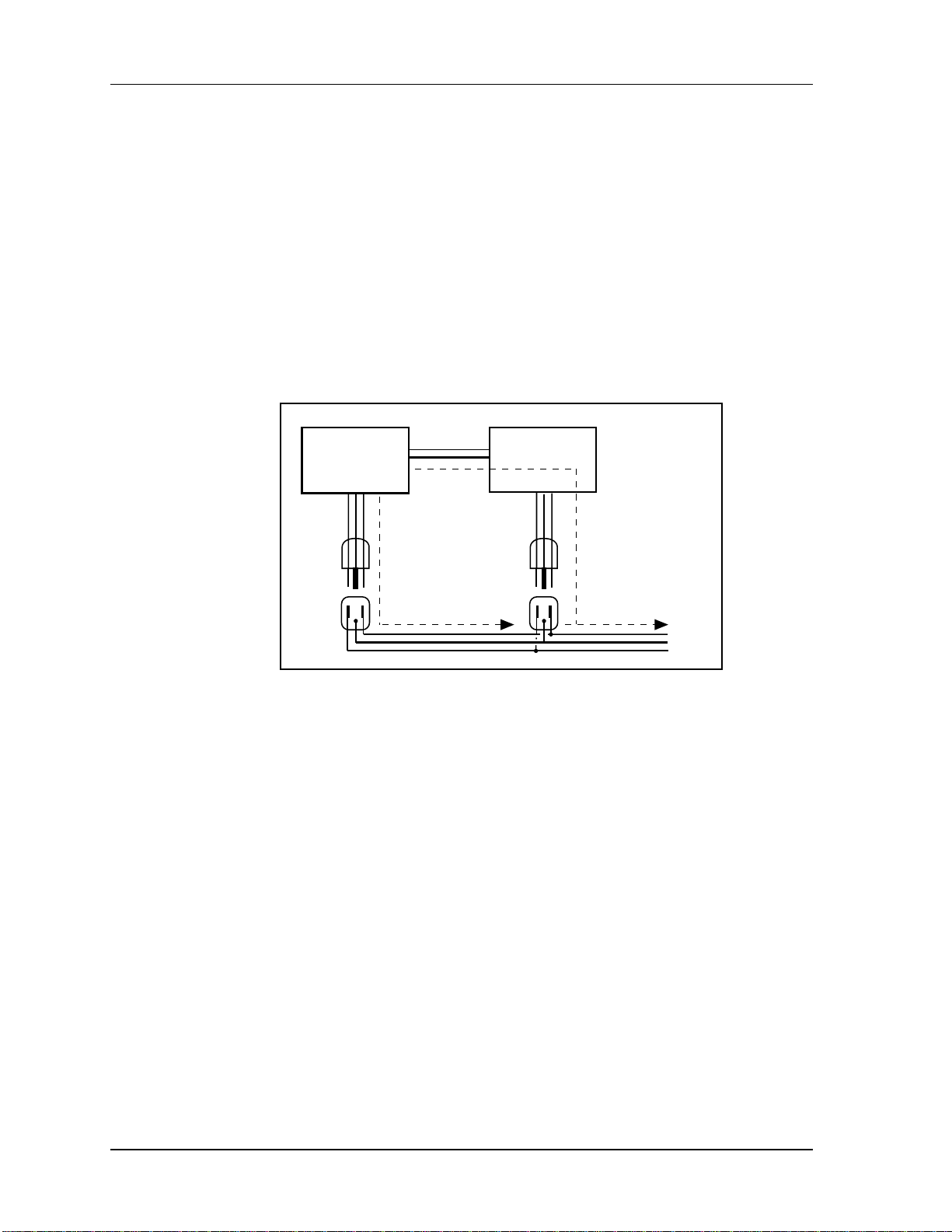
AVOIDING GROUND LOOPS
In today’s studio, where it seems every piece of gear has a computer in
it, there are many opportunities for ground loop problems to occur. These
show up as hums, buzzes, or sometimes radio reception and can occur if a
piece of equipment “sees” two or more different paths to ground, as
shown below.
shielded
cable
Device A
path 1
Device B
path 2
To AC power service
One path goes from device A to ground via the ground terminal of the
three-conductor AC power cord, but A also sees a path to ground through
the shielded cable and AC ground of device B. Because ground wires
have a small amount of resistance, small amounts of current can flow
through ground and generate a voltage along the cable shield. This
signal may end up getting induced into the hot conductor.
The loop can also act like an antenna into which hum is induced, or can
even pick up radio frequencies. Furthermore, many components in a
circuit connect to ground. If that ground is “dirty” and contains noise, it
might get picked up by the circuit. Ground loops cause the most problems with high-gain circuits, since massive amplification of even a
couple millivolts of noise can give an audible signal.
Most ground loop problems can be solved by plugging all equipment into
the same grounded AC source. However, it is important to make sure
that the AC source is not overloaded and is properly rated to handle
the gear plugged into it.
For really tough cases, you may need to break the connection that causes
the loop condition. If your circuits are balanced, one way to do this is to
simply break the shield of the shielded audio cable at some point,
usually by disconnecting it from ground at one jack. (The other end
8 ADAT XT20 Reference Manual
Page 10

Setting Up: Chapter 1
should remain connected so that the shielding properties are retained,
even if there is no direct path for ground.)
Please note that not all hums and buzzes are caused by ground loops;
your cables must be of very high quality, particularly with -10 dBV setups. Refer to page 9 for more information.
ADAT XT20 Reference Manual 9
Page 11

Chapter 1: Setting Up
LINE CONDITIONERS AND PROTECTORS
Although the XT20 is designed to tolerate typical voltage variations,
in today’s world the voltage coming from the AC line may contain
spikes or transients that can possibly stress your gear and, over time,
cause a failure. There are three main ways to protect against this,
listed in ascending order of cost and complexity:
• Line spike/surge protectors. Relatively inexpensive, these are
designed to protect against strong surges and spikes, acting somewhat
like fuses in that they need to be replaced if they’ve been hit by an
extremely strong spike.
• Line filters. These generally combine spike/surge protection
with filters that remove some line noise (dimmer hash, transients from
other appliances, etc.).
• Uninterruptible power supply (UPS). This is the most
sophisticated option. A UPS provides power even if the AC power line
fails completely. Intended for computer applications, a UPS allows you
to complete an orderly shutdown of a computer system in the event of a
power outage, and the isolation it provides from the power line
minimizes all forms of interference—spikes, noise, etc.
ABOUT AUDIO CABLES
The connections between the XT20 and your studio are your music’s lifeline, so
use only high quality cables. These should be low-capacitance shielded cables
with a stranded (not solid) internal conductor and a low-resistance shield.
Although quality cables cost more, they do make a difference. Route cables to
the XT20 correctly by observing the following precautions:
• Do not bundle audio cables with AC power cords.
• Avoid running audio cables near sources of electromagnetic interference
such as transformers, monitors, computers, etc.
• Do not place cables where they can be stepped on. Stepping on a cable
may not cause immediate damage, but it can compress the insulation between
the center conductor and shield (degrading performance) or reduce the cable’s
reliability.
• Avoid twisting the cable or having it make sharp, right angle turns.
• Never unplug a cable by pulling on the wire itself. Always unplug by
firmly grasping the body of the plug and pulling directly outward.
• Although Alesis does not endorse any specific product, chemicals such
as Tweek and Cramolin, when applied to electrical connectors, are claimed to
improve the electrical contact between connectors.
10 ADAT XT20 Reference Manual
Page 12
Setting Up: Chapter 1
BASIC AUDIO HOOKUP
✪
When connecting audio cables and/or turning power on and off, make sure that
all devices in your system are turned off and the volume controls are turned
down.
The XT20 provides eight -10dBV unbalanced analog outputs via phono
connectors. These should be connected to your mixer’s tape or line inputs.
Alternatively, a multi-pin connector can be used with the XT20’s +4dBu
balanced analog inputs and outputs (see Chapter 3).
Mixer Inputs Bus Outputs
INPUT NORMALING
The XT20 has eight analog inputs, but you can choose between three
different Input Modes: 2-Input Mode, 4-Input Mode and 8-Input Mode.
These can provide three different analog audio input hookup options,
and are available for both -10 dBV and +4dBu analog inputs:
• 2 Bus Mixer. Connect the mixer’s two bus outputs to the XT20’s
INPUTS [1] and [2]. Select 2-Input Mode on the XT20 by holding the
[ANALOG INPUT] button and pressing either Track Select buttons [1]
or [2]; notice that the INPUT LEDs for tracks 1 and 2 remain lit until
you release the [ANALOG INPUT] button.
• 4 Bus Mixer. Connect the mixer’s four bus outputs to the XT20’s
INPUTS [1] through [4]. Select 4-Input Mode by holding the [ANALOG
INPUT] button and pressing either Track Select buttons [3] or [4]; notice
that the INPUT LEDs for tracks 1 through 4 remain lit until you release
the [ANALOG INPUT] button.
• 8 Bus Mixer/Direct Outputs. Connect the mixer’s eight bus
outputs (or 8 direct outputs) to the XT20’s INPUTS [1] through [8].
Select 8-Input Mode by holding the [ANALOG INPUT] button and
ADAT XT20 Reference Manual 11
Page 13

Chapter 1: Setting Up
“THREADED” VS. “UNTHREADED”
The XT20 uses a rotating head drum which allows it to record and play back
digital audio signals from the tape. Even when the tape is stopped, it remains
“threaded” or engaged against the spinning heads for a period of time. This
allows for going into play or record faster, as well as “cue” and “review”
functions that let you monitor the tape audio in fast forward or rewind.
When the tape is unthreaded (the [STOP] LED will be flashing), the head is
not spinning and it takes slightly longer to go into play or record. This is because
the tape moves away from the head automatically after being stopped for 4
minutes, in order to prolong tape and head life. When a tape is threaded,
rewinding or fast forwarding will operate 40 times faster than normal play
speed. Cue and review functions are not possible while the tape is unthreaded.
pressing any Track Select button from [5] - [8]; notice that the INPUT
LEDs for tracks 1 through 8 remain lit until you release the [ANALOG
INPUT] button.
In the first two modes, the XT20 internally connects the inputs to the
higher tracks (for example, Input 1 goes to tracks 1, 3, 5 and 7 in 2-Input
mode).
When the tape is threaded and stopped (the [STOP] LED will remain lit), you
can manually unthread it by pressing the [STOP] button. The [STOP] LED will
flash, indicating the tape is now unthreaded. Pressing either [PLAY] or [STOP]
will re-thread the tape (or by simultaneously pressing [PLAY] and [RECORD]
to engage recording).
If the tape is threaded, and no transport activity (play, record, rewind, etc.)
occurs for 4 minutes, the tape will automatically unthread itself to minimize
tape wear.
A WORD ON ADAT’S S-VHS CASSETTE
TAPE
Alesis recommends you use only premium quality, name brand S-VHS cassettes.
We cannot overemphasize the importance of this. We recommend using
Quantegy 489 DM Digital Mastering Audio Tape , or Alesis ADAT Mastering
Audio Cassettes . Other acceptable brands include Maxell XR-S Black , JVC XZ ,
Sony DASV , BASF Digital Master 938 , Apogee AA-40 , HHB ADAT45 , and
TDK SP Super Pro . The cassette shell, hubs, rollers and tape guides in S-VHS
cassettes are precision devices that properly handle and protect the tape
within them.
✪
Do not use inexpensive, budget VHS tapes. ONLY USE S-VHS TAPES.
We do not recommend that you use inexpensive, budget VHS cassettes. While
they may work technically, their unpredictable quality and less-thanpremium formulation will decrease the reliability of your recording. Inferior
tapes not only jeopardize the recordings made on them, they may shed oxide
12 ADAT XT20 Reference Manual
Page 14

Setting Up: Chapter 1
and leave behind a coating of dirt that will interfere with future recordings,
even if you switch back to premium quality tape. Defective tape may even clog
the head, requiring service. Don’t trust your work to anything less than
premium quality S-VHS tape.
Accidents can happen – so, like computer floppy disks and hard disks, your
XT20 tapes should be backed up to prevent loss. Back up your tapes to another
XT20 or ADAT using the fiber optic digital connector (see Making Digital
Backups on page 81).
Treat your tapes as the precision, fragile components that they are. Do not
expose them to extremes of heat, cold, or humidity (in other words, don’t leave
them in your car). Never place tapes near magnetic fields (such as power amps,
TVs, monitors, magnets, etc.) and handle tapes gently.
OPERATING ENVIRONMENT
T
HERMAL CONSIDERATIONS IN RACK MOUNTING
The XT20 can be mounted in an equipment rack (taking up 3 rack spaces)
or placed on a table or shelf. When you install it, keep in mind that
heat is the major enemy of electronic equipment. Please observe the
following:
• The XT20 is designed to perform properly over a range of ambient temperatures from 10° C to +40° C (50° F to 104° F), in up to 80% noncondensing humidity. These are not absolute limits, but Alesis cannot
guarantee that the XT20 will meet its published specs or remain
reliable if operated outside of these ranges.
• Always allow adequate ventilation behind the XT20 . Do not
seal any enclosure that holds the XT20 . It is not necessary to leave an
empty rack space above or below the XT20 unless it runs hot enough to
affect equipment above or below it. If your environment is unusually
warm and not air conditioned, space between units will help the units
run cooler and may lessen tape oxide shedding.
• You will need to remove the screw-on feet from the bottom of
the XT20 if any equipment will be mounted directly below it.
MOUNTING ON A SHELF OR NON-RACK ENCLOSURE
To mount the XT20 on a shelf or other flat surface, Alesis recommends
using the attached screw-on feet to avoid scratching the shelf’s surface
with the deck’s bottom.
Please observe the general comments on thermal considerations given
under “Thermal Considerations in Rack Mounting” no matter where or
how the deck is mounted.
AVOIDING ELECTROMAGNETIC INTERFERENCE
Like all tape machines, the XT20 uses magnetic tape that can be
sensitive to electromagnetic interference. Generally this is not a
problem, but avoid mounting the XT20 next to devices that generate
ADAT XT20 Reference Manual 13
Page 15

Chapter 1: Setting Up
strong magnetic fields such as power amplifiers, monitors and video
display devices, speakers, etc.
14 ADAT XT20 Reference Manual
Page 16
Your First Session With The ADAT XT20: Chapter 2
CHAPTER 2
YOUR FIRST SESSION
WITH THE ADATXT20
POWER-UP, AND TAPE INSERTION
Connect the power cord which accompanies the XT20 between the three-prong
power socket on the back panel and an AC outlet receptacle. Please note that
there are grounding considerations to be aware of. See pages 7–9 for more
information.
✪
The XT20 can produce a transient audio signal during power up and power down.
When turning the XT20 on or off, be sure to keep monitor levels low.
Turn the XT20’s power on by pressing the [POWER] button. At power-up the
display will briefly look like this:
20bit
In a few seconds, the display will change depending on the status of the tape
chamber.
• If a formatted tape is present, the TIME counter will show the elapsed
time since the beginning of the tape (unless it is somewhere in the first two
minutes of tape, called the “lead” and “data” sections):
ABS
0H 15M 48S 21
• If an unformatted tape is present, the FORMAT icon will flash and the
TIME counter will read:
ABS
n0 F0
• If there is no tape, the display shows:
ADAT XT20 Reference Manual 15
Page 17

Chapter 2: Your First Session With The ADAT XT20
ABS
-- -- -- --
Insert the tape with the hinged door end first, label side up, until you encounter
a slight bit of resistance. Push gently on the center of the tape cassette until the
XT20 draws the tape inward; never force the tape into the cassette door.
16 ADAT XT20 Reference Manual
Page 18

Your First Session With The ADAT XT20: Chapter 2
FORMATTING A TAPE – A MUST!
Formatting prepares a tape for 8 channels of audio, and adds a master timecode
reference, word length, and sample rate information to the data on tape.
Similar to formatting a floppy disk to use on a computer or sampler, formatting
an XT20 tape time-stamps the tape to single-sample accuracy so that audio is
referenced to an accurate time base. This makes the synchronization process
between XT20 and ADAT compatible machines possible and provides both
accurate tape counter readings and intelligent autolocation functions. For more
information, see Tape Formatting in Chapter 4. After completing the following
exercise, we recommend you perform a complete format.
✪
Formatting a tape erases audio on all eight tracks. Be sure to check that the
tape is either blank or contains unwanted material before formatting. We
recommend that you format your tapes completely from beginning to end.
WORD LENGTH (16/20 BIT ) SELECTION
Before formatting, select the word length you will be using (either 16bit or 20-bit) by pressing the FORMAT button until the length you want
is shown in the display. 20-bit offers the greatest audio quality; 16-bit
should be used if the master tape must be played in an older, Type-Ionly ADAT or ADAT-XT. (You can always make a 16-bit copy of a 20bit master if needed for this purpose.)
SAMPLE RATE SELECTION
Before formatting, select the sample rate you will be using (either 48
kHz or 44.1 kHz). This is done by pressing the [CLOCK SELECT]
button. Each time [CLOCK SELECT] is pressed, the XT20 will cycle
between INT 48K, INT 44.1K and DIG (the section on the right side
of the display labeled CLOCK will indicate the currently selected
sample rate). Note: For more information about the DIG option
(Digital Audio Clock), see page 59.
FORMATTING A NEW TAPE
To Format a new tape:
❿ Insert a fresh, blank tape.
The XT20 will acknowledge that this is an unformatted tape; the
FORMAT icon will flash in the display while the counter display
reads “noFO.”
❡ Press the [FORMAT] button.
The display will briefly read “20 bit” or “16 bit” The word [FORMAT]
in the display will stop flashing and remain lit. The [RECORD] LEDs
for tracks 1 through 8 will now be flashing.
① Hold [RECORD], and then press [PLAY].
If the tape was not completely rewound, the XT20 will automatically
rewind it to the beginning. The XT20 then performs a complete format
by recording 15 seconds of leader (the LED display will read “LEAd”),
followed by two minutes of data (the display will read “dAtA”), then
timecode starting at 0:00:00.00 and continuing to the end of the tape.
ADAT XT20 Reference Manual 17
Page 19

Chapter 2: Your First Session With The ADAT XT20
RECORDING WHILE FORMATTING
You can record onto tape while formatting. Simply press any of the
RECORD ENABLE buttons [1]–[8] for any track(s) you wish to record on
before pressing the [FORMAT] button. Prepare your source material to
start playback at 0:00:00.00 on the XT20 or later (do not begin recording
before 0:00:00.00). See the next section for more information on setting
levels and recording.
18 ADAT XT20 Reference Manual
Page 20

Your First Session With The ADAT XT20: Chapter 2
MAKING A RECORDING
Recording on the XT20 is very similar to most multitrack tape machines. The
process involves formatting a tape (see previous tutorial), putting one or more
tracks into record-ready, adjusting record levels on your mixer, setting the input
monitor mode, locating to the start tape address and engaging record. In this
tutorial, we will be recording from the analog audio inputs at the start of the
audio portion of the tape (0:00:00.00).
TRACK SELECTION AND SETTING LEVELS
You’ll find the RECORD ENABLE buttons ([1]–[8]) for all eight tracks
on the left side of the front panel, beneath the display. A track is
considered “safe” when its [REC] LED is off, in “record-ready” when its
[REC] LED is flashing, and in record when its [REC] LED is lit solid.
To record-enable a track:
❿ Choose a track to record on, and press the track’s associated
RECORD ENABLE button [1]–[8]. The selected track’s [REC] LED will
flash to indicate it is in record-ready.
❡ Send an audio signal to the track(s) you have placed into
record-ready.
Adjust the levels on your mixer so that the “average” level is at -15 dB
on the peak meters of the XT20 and the loudest section never goes
beyond 0 dB. Digital audio recording is different from analog recording,
and therefore requires a different method when setting levels. For more
information, see Setting Levels on page 48.
① To take a track out of record-ready (safe), press its associated
RECORD ENABLE button again. The selected track’s [REC] LED will
turn off to indicate it is safe.
TIME COUNTER
Before recording, you should familiarize yourself with the transport
buttons, and the 7-segment TIME counter in the top left corner of the
display. Ordinarily, the TIME counter will show Absolute (ABS) time,
which is the exact time reference being read directly off of the
formatted tape. The tape position is displayed as hours:minutes:
seconds.hundredths-of-a-second. (This counter may be changed to show
30 frames per second, see page 60 for more information.)
ABS
0H 15M 48S 21
Pressing the [ABS/REL] button will toggle the display between ABS
Time and Relative Time. The display will either indicate ABS or REL
to the left of the TIME counter.
REL
0H 01M 29S 03
Relative Time reflects the current tape position relative to where you
set the Relative 0:00:00.00 position. This is similar to resetting the
tape counter on a cassette deck. However, the XT20 gives you the option
of reading the actual tape position (ABS Time) or the tape position
relative to the location you marked as 0:00:00.00 (Relative Time).
ADAT XT20 Reference Manual 19
Page 21

Chapter 2: Your First Session With The ADAT XT20
✪
Before you start recording for the first time, be sure the TIME counter is
set to ABS Time to avoid confusion. For more information, see page 41.
20 ADAT XT20 Reference Manual
Page 22
Your First Session With The ADAT XT20: Chapter 2
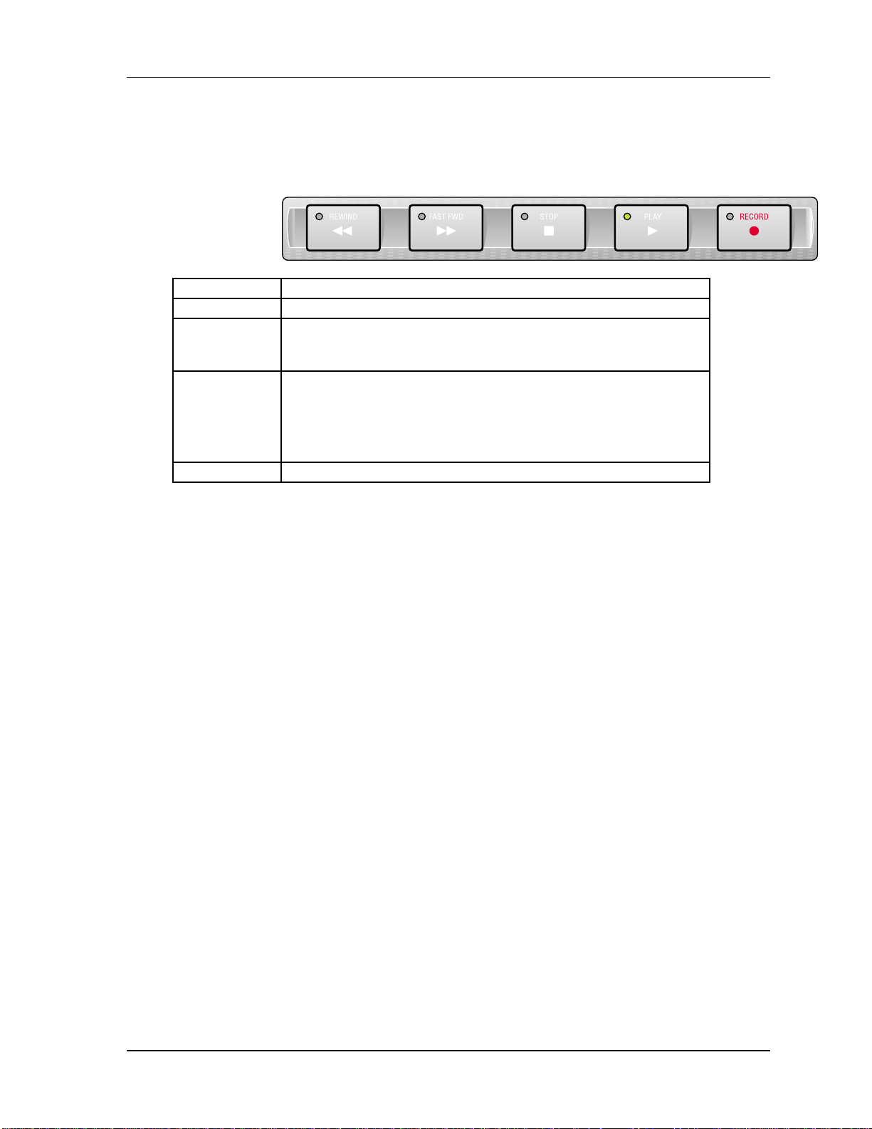
TRANSPORT BUTTONS
During recording and playback, the following transport buttons are used
frequently. Get familiar with them by using them while watching the
TIME counter.
REWIND High speed reverse. Press with [PLAY] to initiate review mode.
FAST FWD High speed forward. Press with [PLAY] to initiate cue mode.
STOP
PLAY
RECORD Press with [PLAY] to initiate recording.
Stops transport and disables recording.
While the transport is stopped, this button toggles between
threaded (LED is lit) and unthreaded modes (LED is flashing).
Starts playback. Initiates recording when pressed with
[RECORD].
Stops recording when in record mode while continuing to play.
Press with [FAST FWD] to initiate Cue mode.
Press with [REWIND] to initiate Review mode.
RECORDING
Recording takes place only on tracks that are in record-ready. When
you start recording, the [RECORD] LED lights, and the [REC] LEDs for
those tracks in record-ready will stop flashing and remain lit. If no
tracks are in record-ready when recording takes place, the [RECORD]
LED will flash to indicate that pressing any of the RECORD ENABLE
buttons will initiate recording on the selected track.
To make a recording:
❿ Use the [REWIND] or [FAST FWD] button to locate to the
desired tape position
Either the [REWIND] or [FAST FWD] LED will light (depending on
which button was pressed), indicating that the transport is moving in
that direction. The TIME counter will indicate the current tape location
status while the transport is in motion.
❡ When you’ve arrived at the desired tape address, press the
[STOP] button.
The [STOP] LED lights.
① Hold [PLAY], and then press [RECORD].
Both the [PLAY] and [RECORD] LEDs will light to indicate you are
recording.
➃ To go in and out of record on the individual tracks while record
mode is engaged, press any of the RECORD ENABLE buttons [1] – [8].
Record-enabled tracks will have their REC LED lit. If no tracks are
record-enabled during recording, the [RECORD] LED will flash.
➄ To punch out without stopping, press [PLAY].
The [RECORD] LED turns off, while the [PLAY] LED remains lit.
➅ To punch out and stop the transport, press [STOP]
The [RECORD] and [PLAY] LEDs turn off; the [STOP] LED lights.
ADAT XT20 Reference Manual 21
Page 23

Chapter 2: Your First Session With The ADAT XT20
Note: When recording for the first time, be sure the Auto Input function
is off. When recording over previous material (also known as punching),
turn the Auto Input function on. Use the [AUTO INPUT] button to turn
Auto Input on and off. The AUTO INPUT icon will light in the display
when Auto Input is on.
PLAYBACK
There are several ways to quickly play back your recording. You’ll use
the transport buttons first.
To play back a recording:
❿ Press [REWIND] to locate back to a tape position before you
engaged recording.
The [REWIND] LED will light and the TIME counter will roll
backward to indicate the current tape location status while the
transport is in motion.
❡ Once you have arrived at the desired tape address, press the
[STOP] button.
The [REWIND] LED will turn off and the [STOP] LED will light.
① Press [PLAY].
The [PLAY] LED will flash briefly, and then will light to indicate
play mode has been engaged.
➃ Press [STOP] to stop playback.
The [PLAY] LED will turn off and the [STOP] LED will light.
REVIEWING AND CUEING
When you are trying to locate a particular section of a recording, it is
often helpful to use the review and cue modes on the XT20. Review
mode lets you play the tape in reverse at a speed 3 times faster than
play while hearing “fragments” of audio. Cue mode, on the other hand,
plays forward at a speed 3 times faster than Play mode while also
letting you hear “chunks” of audio. By listening to the audio in either
mode, you can quickly find the section you are looking for.
To engage Review mode:
❿ Simultaneously press [REWIND] and [PLAY].
The [PLAY] LED will light and the [REWIND] LED will flash.
❡ Press [PLAY] to resume Play mode.
The [PLAY] LED will remain lit while the [REWIND] LED will turn
off.
① Alternatively, you can press [STOP] to stop the transport.
Both the [PLAY] and [REWIND] LEDs will turn off, and the [STOP]
LED will turn on.
To engage Cue mode:
❿ Simultaneously press [FAST FWD] and [PLAY].
The [PLAY] LED will light and the [FAST FWD] LED will flash.
❡ Press [PLAY] to resume Play mode.
The [PLAY] LED will remain lit while the [FAST FWD] LED will turn
off.
① Alternatively, you can press [STOP] to stop the transport.
22 ADAT XT20 Reference Manual
Page 24

Your First Session With The ADAT XT20: Chapter 2
Both the [PLAY] and [FAST FWD] LEDs will turn off, and the [STOP]
LED will turn on.
ADAT XT20 Reference Manual 23
Page 25

Chapter 2: Your First Session With The ADAT XT20
LOCATING
Up to 10 tape positions can be stored for easy recall. These are called Locate
Points, and can be stored either “on the fly” while the transport is engaged, or
when the transport is stopped. Once a Locate Point is stored, its corresponding
tape position can be edited. For more info about locating and editing Locate
Points, see pages 55-6.
✪
Each Locate Points’ tape position will be shown in either ABS Time or Relative
Time, depending on which is selected. The tape positions themselves, however,
do not move when switching between these modes.
To store locate points “on the fly”:
❿ Press [PLAY], [FAST FWD] or [REWIND] to set the tape transport in
motion.
❡ Press or hold [SET LOCATE].
The LOCATE icon will appear in the display immediately followed by a
flashing dash (–).
① While holding [SET LOCATE] (or within two seconds after releasing
[SET LOCATE]), press one of the [LOCATE 1] through [LOCATE 9] buttons.
The current tape position is transferred into the selected Locate Point.
To edit locate points:
❿ Press the [EDIT VALUE]button.
The EDIT icon will appear in the display along with one of three icons
appearing below it: LOCATE, TAPE OFFSET or TRACK DELAY.
❡ Use [LOCATE 0] through [LOCATE 9] buttons to select a Locate Point
Memory.
The LOCATE icon will appear (if not already present) and a number from 0 to 9
will appear to its right to reflect the button you have pressed.
① Hold [EDIT VALUE] and use the [LOCATE 0] – [LOCATE 9] buttons
as a numeric key-pad (0-9) to enter the tape position you wish to set for the
selected Locate Point.
Enter the tape position from left to right. Example: To enter 0:05:00.00, you
would hold [EDIT VALUE] and type [LOCATE 5], [LOCATE 0], [LOCATE
0], [LOCATE 0], [LOCATE 0].
➃ Use the [▲] and [▼] buttons to fine adjust the Locate Point address as
desired.
To recall a locate point:
❿ Press one of the [LOCATE 1] through [LOCATE 9] buttons.
Either fast forward or rewind will engage, as indicated by either button’s LED.
When the locate function is complete, the transport will stop, and the [STOP]
LED will light. If you wish the transport to automatically go into play after
the locate function is complete, turn on Auto Play (see next section).
24 ADAT XT20 Reference Manual
Page 26

Your First Session With The ADAT XT20: Chapter 2
To set the Relative 0:00:00.00 position (Locate 0):
❿ Press [PLAY], [FAST FWD] or [REWIND] as required to move the tape
to the position you wish to regard as “0:00:00.00” (Relative Time).
Remember, ABS Time is the timecode being read from tape. Setting the Locate 0
position is always done in Relative Time.
❡ Press [SET LOCATE], immediately followed by pressing [LOCATE 0].
The current tape position is stored into Locate 0, and the TIME counter will
display :
REL 0H 00M 00S 00
CREATING A LOOP
The Auto Return function causes the XT20 to automatically rewind back to a
specified tape position (Locate 1) when playback or recording has reached a
specified position (Locate 4). Both Locates 1 and 4 are assignable to any tape
position using the methods described in the previous section.
The Auto Play function is used to automatically engage playback whenever a
locate function is completed. By using both the Auto Return and Auto Play
functions, a loop can be created whereby the same region of tape is repeatedly
played back. For more information on related functions, see the section entitled
Autolocation Controls in Chapter 4.
To loop a section of tape:
❿ Store the tape position where you want the loop to begin into [LOCATE
1].
Refer to the previous section for instructions.
❡ Store the tape position where you want the loop to end into [LOCATE
4].
① Press [AUTO RETURN] to enable Auto Return.
In the right side of the display, the AUTO-RETURN icon will appear
indicating that Auto Return is enabled. The XT20 will now automatically
rewind back to the tape position stored in Locate 1 upon reaching the tape
position stored in Locate 4.
➃ Press [AUTO PLAY] to enable Auto Play.
In the right side of the display, the AUTO-PLAY icon will appear indicating
that Auto Play is enabled. The XT20 will now automatically engage playback
upon completing a locate.
➄ If necessary, press [REWIND] to rewind the tape to a location that is
before Locate 4’s position.
➅ Alternatively, you can press [LOCATE 1] to locate directly to its
stored tape position.
➆ Press [PLAY] to engage playback.
The [PLAY] LED will light and the transport will go into Play mode. When
Locate 4’s position is reached, the tape will automatically rewind back to
Locate 1’s position and then automatically go back into Play mode.
✪
ADAT XT20 Reference Manual 25
Page 27

Chapter 2: Your First Session With The ADAT XT20
If the current Locate 1 position is set beyond the current Locate 4 position and
Auto Return is turned on, the AUTO-RTN icon in the display will flash to
indicate that Locate 1 or 4 will have to be set properly before this function will
operate.
26 ADAT XT20 Reference Manual
Page 28

Your First Session With The ADAT XT20: Chapter 2
AUTOMATED RECORDING
So far, all of your recording has been done manually — you pressed the
transport buttons when you wanted to start and stop recording. Auto recording
stops and starts recording automatically at predetermined times. This is useful
when you want to precisely punch in to a specific place on one or more tracks.
In this section, we will be storing the punch points (called Punch In and Punch
Out) “on the fly” while playback is engaged. You can, however, manually
modify the precise Punch In and Out points. Auto Return and Auto Play
(described in the previous section) help make Auto Recording more functional.
For more information, see page 58.
To automatically punch in and out:
❿ Store the tape position where you want to begin recording into
[LOCATE 2].
Refer to page 67 for instructions.
❡ Store the tape position where you want to end recording into [LOCATE
3].
① Press [AUTO RECORD] to enable Auto Record.
In the right side of the display, the AUTO-REC icon will appear indicating
that Auto Record is enabled. Note: If Locate 2’s position is past Locate 3’s
position, the TIME counter will temporarily read “invALid”.
➃ Press [REWIND] to rewind the tape before Locate 2’s position.
➄ Record enable the track(s) you wish to record on.
The selected tracks’ [REC] LEDs flashes.
➅ Simultaneously press [PLAY] and [RECORD].
The [PLAY] LED lights, the [RECORD] LED flashes and the transport will
engage Play mode. When Locate 2’s position is reached, the XT20 will
automatically punch-in ([PLAY], [RECORD] and track [REC] LED(s) stop
flashing and remain lit). Recording will continue until Locate 3’s position is
reached, at which point the XT20 will automatically punch-out, returning to
play mode ([PLAY] LED lit, [RECORD] LED off, track [REC] LEDs flashing).
➆ Press [STOP] to stop the transport.
✪
If none of the tracks are in record-ready (all eight [REC] LEDs off) when the
punch-in point is reached, the [RECORD] LED will continue flashing instead
of lighting solid.
✪
If a record is initiated past Locate 2’s position, but before Locate 3’s position,
then record is entered immediately. If the record is initiated after Locate 3’s
position, then the record command is ignored and the transport is left in play
mode.
REHEARSING
By pressing the [REHEARSE] button (the REHEARSE icon will light in
the display), you can run through the Auto-Record process without
actually recording anything. However, the input monitors on the tracks
ADAT XT20 Reference Manual 27
Page 29

Chapter 2: Your First Session With The ADAT XT20
that enabled for recording will switch from tape to input when the
punch-in occurs, and back to tape when the punch-out occurs (this
requires that the AUTO INPUT function be turned on). The [RECORD]
LED will continue flashing throughout the punch in and out. This way
you can try out your punch locations first without recording over
anything. In other words, you can measure twice (or more), and cut only
once!
28 ADAT XT20 Reference Manual
Page 30

Your First Session With The ADAT XT20: Chapter 2
PITCH CONTROL
The Pitch function controls the speed of the tape, and thus the pitch of the
audio recorded on tape. The XT20’s Pitch control has a range of -300 to +100
cents when using a sample rate of 48kHz, and a range of -200 to +200 cents when
using 44.1kHz. Use the PITCH [▲] and [▼] buttons to control the amount of
pitch change. When either button is pressed once, the PITCH icon lights in the
display, and the TIME counter immediately displays the current amount of
Pitch change. The Pitch amount is displayed both as a percentage (%) and as
cents.
ABS
To set the Pitch amount:
00
(Percentage) / (Cents)
00% 00. 00
.
C
❿ Press and hold either PITCH [▲] or [▼].
After holding for more than two seconds, the Pitch amount will start either
increasing or decreasing, depending on which button was pressed.
TRACK DELAY
The XT20 allows you to delay the playback of any track in relation to the other
tracks (and the TIME counter) by a maximum of 170 milliseconds. This can be
very useful when some tracks are slightly “off”, or when you need to move a
particular instrument to get it “in the pocket”, or when you just want to create an
interesting effect (like copying a track and delaying the copy).
To delay a track:
❿ Press [EDIT VALUE].
The EDIT icon will light in the display.
❡ Press [TRACK DELAY].
The TRACK DELAY icon will light, just below the EDIT icon.
① Choose a track to edit by pressing one of the RECORD ENABLE buttons
[1]–[8].
A number will appear to the left of the EDIT icon representing the track you
are editing.
➃ Use the [▲] and [▼] buttons to adjust the delay amount in .1 ms
increments.
➄ Hold the [EDIT VALUE] button and enter a specific delay value using
the [LOCATE 0] thought [LOCATE 9] buttons.
The TIME counter will display the selected track’s delay amount.
1 70. 0 mS
Simultaneously, the peak meter for the selected track will rise to indicate the
amount of track delay you have selected.
➅ Repeat steps 3 and 4 for any other tracks you wish to delay.
➆ Press [EDIT VALUE] to exit Edit mode.
The EDIT icon will turn off.
♠ Press [TRACK DELAY] to enable the Track Delay feature.
The TRACK DELAY icon will light, indicating that track delays are now in
effect.
ADAT XT20 Reference Manual 29
Page 31

Chapter 2: Your First Session With The ADAT XT20
❻ If necessary, repeat steps ❿ through ➄ to edit the delay value of any
track.
30 ADAT XT20 Reference Manual
Page 32

Your First Session With The ADAT XT20: Chapter 2
TRACK COPY
It is possible to copy the audio material from one track to another on the same
tape within the XT20 without leaving the digital domain and without the
need for any audio cables. In fact, you can copy up to 4 tracks at a time using the
Track Copy feature. For more information on using the Track Copy function, see
page 44.
To bounce audio from one track to another:
❿ Press and hold [TRACK COPY].
The TRK COPY icon will light in the display.
❡ While holding [TRACK COPY], select a source track (up to 4) by
pressing any of the RECORD ENABLE buttons [1]–{8].
The INPUT LEDs for the selected track(s) will light. Note: You can’t select a
track that is already in record-ready (REC LED lit) as a source track; if its
RECORD ENABLE is pressed, its INPUT LED won’t light while holding the
[TRACK COPY] button.
① Release [TRACK COPY], and choose a destination track (up to 4) by
pressing one of the RECORD ENABLE buttons [1]–[8].
The REC LEDs for the selected track(s) will light. Note: You cannot select a
source track as a destination track; if its RECORD ENABLE is pressed, its REC
LED won’t light.
➃ Use the [REWIND], [FAST FWD] or [LOCATE 0] through [LOCATE
9] buttons to move to the section of tape which holds the audio you wish to
copy.
➄ Simultaneously press [RECORD] and [PLAY] to initiate recording.
The [RECORD] and [PLAY] LEDs will light and recording will begin.
➅ When you are finished, press [STOP].
The [STOP] LED will light and the transport will stop.
✪
While the TRK COPY icon is lit (indicating that Track Copy mode is
selected) you will not be able to record any audio being fed to the analog or
digital inputs. To record from the analog inputs, you must press the [ANALOG
INPUT] button (the ANALOG icon will light in the display).
DISPLAY BRIGHTNESS
If necessary, the brightness of the XT20’s display may be adjusted to allow more
suitable viewing under various lighting conditions.
To adjust the display brightness:
❿ Hold the [PEAK CLEAR] button.
❡ While still holding [PEAK CLEAR], press either PITCH [▲] or [▼] to
dim or brighten.
The display will immediately respond by either dimming or brightening,
depending on which button was pressed.
ADAT XT20 Reference Manual 31
Page 33

Chapter 2: Your First Session With The ADAT XT20
32 ADAT XT20 Reference Manual
Page 34

CHAPTER 3
CONNECTIONS
ANALOG AUDIO – UNBALANCED INPUTS
I
NPUT JACK CHARACTERISTICS
The XT20 includes eight unbalanced phono jack inputs. These are
compatible with low-impedance, unbalanced, -10 dBV outputs typical
of equipment such as mixers, synthesizers, samplers, direct boxes, etc.
The unbalanced input jack wiring convention is as follows:
TipSignal
SleeveGround
Connections: Chapter 3
Tip
Sleeve
TYPICAL INPUT JACK HOOKUPS
The input jacks are typically hooked up in one of three ways:
• To the console’s direct tape outs (these patch a single channel
directly to tape, bypassing most mixer circuitry). This is preferred
when the signals going to tape require none of the mixer’s features
(effects, grouping, routing, etc.).
• To eight mixer bus outputs. You can use the mixer for grouping,
premixing, effects, etc. This puts more circuitry between the input
signals and XT20, although since most routing can be done at the mixer,
you’ll seldom need to do any repatching.
• To a combination of direct outputs and bus outputs. Some
situations require a combination of the two approaches. Example:
Consider a live gig you want to record with two vocal mics, four mics on
drums, two direct feeds from guitar and bass amps, and one direct feed
from keyboards. The vocals, bass, guitar, and keyboards could be taken
direct and go to five XT20 tracks. The four drum mics can be mixed to
stereo within your mixer sent to the submix outs, then go to two XT20
tracks. The remaining XT20 track could be used to record audience sounds
or capture one of the instruments in stereo, if applicable.
ANALOG AUDIO – UNBALANCED OUTPUTS
The -10 dBV outputs use phono (sometimes called “RCA”) jacks, and carry
signals at a nominal -10 dBV level (.316 volts). These should be connected to
ADAT XT20 Reference Manual 33
Page 35

Chapter 3: Connections
your mixer’s channel tape returns or line inputs. The outputs wiring scheme is
similar to that of the unbalanced inputs (see previous section).
34 ADAT XT20 Reference Manual
Page 36

Connections: Chapter 3
ANALOG AUDIO – BALANCED INPUTS AND
OUTPUTS
To run long distances and avoid hum and noise, use the balanced input/output
feature of your ADAT-XT20. To do so, your mixer must have balanced inputs
and outputs as well. The +4 dBu line inputs and outputs use an ELCO® multipin
connector. You may purchase an ELCO-to-1/4” TRS or ELCO-to-XLR cable
assembly from your dealer. The balanced in/out connector wiring scheme is as
follows:
INPUTS
OUTPUTS
Larger Key Notch
Note: The larger of the two outer key notches is at the bottom.
✪
Both the unbalanced and balanced inputs and outputs may be used
simultaneously.
Pin out letters are referenced to the alphabetical designation on a standard 56pin ELCO connector.
Channel GND NEG POS Channel GND NEG POS
In 1 N N JJ H H Out 1 Z c d
In 2 CC y x Out 2 P U V
In 3 t n m Out 3 D J K
In 4 FF MM LL Out 4 T M N
In 5 w B B AA Out 5 H B C
In 6 K K EE DD Out 6 W a b
In 7 z v u Out 7 L R S
ADAT XT20 Reference Manual 35
Page 37

Chapter 3: Connections
In 8 p l k Out 8 A E F
Additional grounds: r, s, h, j, e, f, X, and Y.
®
ELCO is a registered trademark of Elco Corporation - a Kyocera Group Company
36 ADAT XT20 Reference Manual
Page 38

ANALOG INPUT SELECT MODE
The XT20 lets you choose one of three Analog Input Modes for both the
Unbalanced and Balanced inputs:
2-Input Mode Input 1 feeds Tracks 1, 3, 5 and 7.
Input 2 feeds Tracks 2, 4 , 6 and 8.
4-Input Mode Input 1 feeds Tracks 1 and 5.
Input 2 feeds Tracks 2 and 6.
Input 3 feeds tracks 3 and 7.
Input 4 feeds tracks 4 and 8.
8-Input Mode Each Input feeds its own track.
The reason for these three modes is to take equal advantage of 2, 4 and 8 bus
mixing consoles. If you have two buses, connect them to inputs 1 and 2. If using
four buses, connect them to inputs 1 through 4.
To select the appropriate Input Mode, hold the [ANALOG INPUT] button under
the meters and press one of the RECORD ENABLE buttons ([1]–[8]). The
[INPUT] LEDs, located along the bottom of the display below the VU meters,
will light up to indicate the Input Mode you have selected.
Connections: Chapter 3
While holding [ANALOG
INPUT]
Press [1] or [2]...
Press [3] or [4]...
Press [5], [6], [7] or [8]...
When using a 2 bus mixer, connect its two outputs to the XT20’s unbalanced
inputs 1 and 2 and select 2-Input Mode. Anytime you want to record on an odd
number track you will route the signal(s) to bus #1 or left. Likewise, to record
onto an even number track, route the signal(s) to bus #2 or right. By simply
putting the desired track into record, the proper signal will get there, although
not directly connected to the track’s input jack.
When using a 4 bus mixer, connect its four outputs to the XT20’s unbalanced
inputs 1 through 4 and select 4-Input Mode. Anytime you want to record on
tracks 1 or 5 you will route the signal(s) to bus #1. Likewise, to record onto tracks
2 or 6, route the signal(s) to bus #2, and so on.
Result
...to select 2-Input Mode. Tracks 1 and 2
...to select 4-Input Mode. Tracks 1 through 4
...to select 8-Input Mode. All Tracks (1 – 8)
[INPUT] LEDs lit
for...
ADAT XT20 Reference Manual 37
Page 39

Chapter 3: Connections
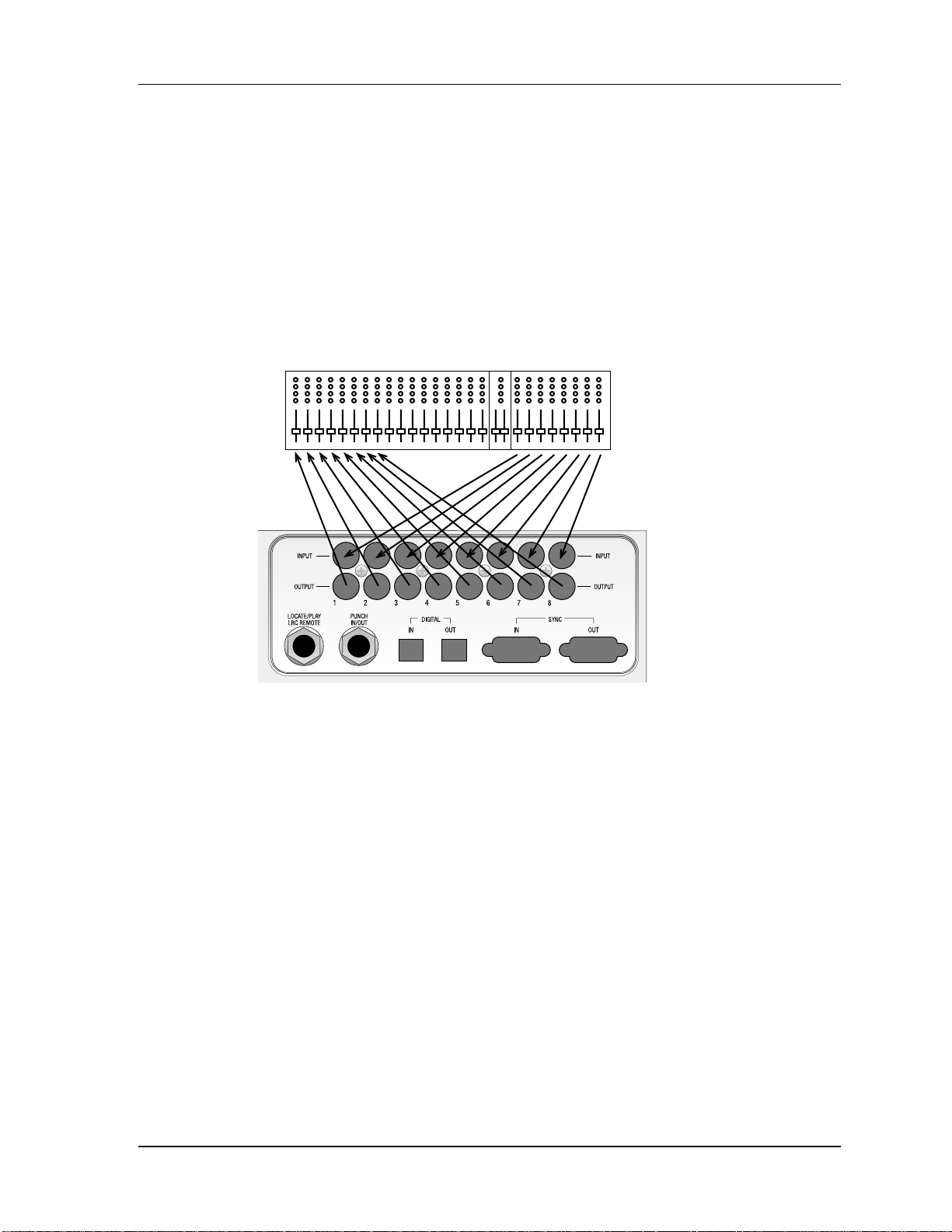
SYNC IN/OUT
The two DB 9 connectors marked [SYNC IN] and [SYNC OUT] are used for
synchronizing two or more XT20s together, or a combination of XT20s and other
ADATs, or a computer hard disc using the ADAT-PCR or similar device. This
requires a male-to-male, 9-pin D connector cable for each additional machine in
the chain. These cables are available in various lengths from your dealer and
should be Alesis-approved; improper cables (such as those used for computers)
may not function correctly.
In such a system, you are basically treating all connected machines as though
they were a large multitrack unit. The first XT20 or ADAT in the chain is
called the “master”, and all other connected units are referred to as “slaves”.
However, each slave can also be used independently when the master machine
is stopped.
For more information about using multiple XT20s and/or ADATs, refer to
chapter 5.
To synchronize multiple XT20s and/or ADATs:
❿ Locate the [SYNC IN] and [SYNC OUT] connectors.
❡ Connect one end of a male-to-male, 9-pin connector cable to the master’s
[SYNC OUT] jack.
① Connect the other end of the cable to the first slave’s [SYNC IN] jack.
➃ For additional slaves, connect one end of a male-to-male, 9-pin D
connector cable to the first slave’s [SYNC OUT] jack, and the other end to the
second slave’s [SYNC IN] jack. Its [SYNC OUT] jack then connects to the third
slave’s [SYNC IN] jack, and so on.
The following illustration depicts two XT20s synchronized together.
INPUT
OUTPUT
INPUT
OUTPUT
38 ADAT XT20 Reference Manual
Page 40

Connections: Chapter 3
DIGITAL AUDIO IN/OUT
The digital input and output carries all eight tracks on a single fiber optical
cable. This allows you to bounce audio between multiple machines within the
digital domain. The ADAT Optical cables carry digital audio between
multiple XT20s and ADATs, and to ADAT Compatible™ products such as the
QuadraVerb 2, Q20, many Alesis keyboards, the ADAT-PCR computer interface
card, and third-party products such as the Digidesign ADAT Interface and
Yamaha 02R digital mixer. Since the fiber optic connector carries the digital
information for all 8 tracks, it is also useful for backing up all tracks in one pass
(see Chapter 6 for more on digital audio).
Digital bussing requires a fiber optical cable (included) for each XT20 in the
system (or any other ADAT-compatible product). Additional cables are
available from your dealer in various lengths up to 16 feet. This connection can
be made while power is on or off, and the machines do not need to be turned on in
any particular order. Note: To bounce tracks within a single XT20, it is not
necessary to connect the optical network.
ABOUT 16-BIT AND 20-BIT SIGNAL TRANSFERS
All data on the ADAT Optical cable is in a 24-bit word length; in 16-bit
mode the eight least significant bits are filled with zeroes, in 20-bit
mode the last four bits are zeroes. If 20-bit data is sent to a 16-bit
machine, the four “extra” bits are simply ignored. Only ADAT Type II
machines (such as the M20, XT20, LX20, and PCR card with proper
software) can receive a full 20-bit transfer via the optical cables (and
then only if the tapes in those machines was formatted in 20-bit mode).
If you need to transfer audio from a Type II tape to a Type I tape you
have three options:
❿ Transmit at 20 bit, and the receiving unit will ignore the last
four bits, essentially cutting them off.
❡ Press the [DIGITAL OUT] button (located on the right above
the RECORD button) until the display reads:
ABS
Ovt 16
This cuts off the data in bits 17-20 and fills the “extra” 4 bits
with zeroes at the transmitting end. In most cases, this has the same
sonic results as Method #1.
① Press the [DIGITAL OUT] button (located on the right above
the RECORD button) until the display reads:
ABS
Ovt 16dt
This adds dither, a specially shaped mathmatical noise, to
the conversion process which “smoothes out” the transition at low
levels and allows you to get better resolution even though the result is
still 16-bit. However, if the signal will be dithered again later, you
may want to use one of the first two methods.
ADAT XT20 Reference Manual 39
Page 41

Chapter 3: Connections
40 ADAT XT20 Reference Manual
Page 42

Connections: Chapter 3
To connect the digital optical network:
❿ Locate the [DIGITAL IN] and [DIGITAL OUT] connectors.
Remove the connectors’ plugs (if present) and store for later use.
❡ Connect one end of the fiber optic cable into the [DIGITAL
OUT] jack of the first machine in the system.
Remove the clear, plastic tube covering each end of the cable (if
present). The cable is non-polarized, so either end can be inserted into
the optical output.
① Connect the other end of the fiber optic cable to the [DIGITAL
IN] of the second machine in the system.
Tip: if the machines are on, the cable from the source machine will
show a red light at the end.
➃ For each additional machine, connect one end of an additional
fiber optic cable to the second machine’s [DIGITAL OUT] jack, and the
other end to the third machine’s [DIGITAL IN] jack. Its [DIGITAL
OUT] jack then connects to the fourth machine’s [DIGITAL IN] jack,
and so on.
➄ Finally, connect one end of a fiber optic cable to the last
machine’s [DIGITAL OUT] jack, and the other end to the first
machine’s [DIGITAL IN] jack.
This last step creates a loop, and thus makes the digital bus accessible
to all machines that are connected to it.
✪
When connecting more than two machines, always connect the optical
cables in the same order as the sync cables (1 to 2, 2 to 3, etc.), so that
the digital routing will work correctly.
INPUT
OUTPUT
INPUT
OUTPUT
ADAT XT20 Reference Manual 41
Page 43

Chapter 3: Connections
FOOTSWITCHES
The XT20 provides two footswitch connectors using 1/4" mono (T/S) jacks. One,
labeled [LOCATE/PLAY LRC REMOTE], allows locate and play commands
when used with a standard footswitch, or more elaborate control when used
with the LRC Remote control; the other, labeled [PUNCH IN/OUT ], is for
punch in/out control.
The two footswitch jack functions are designed to be used with any momentary
single-pole/single-throw footswitch (either normally open or normally closed).
These should be plugged in prior to power-up so that the XT20 can configure
itself for the type of footswitch being used.
✪
The Punch In/Out footswitch and XT20 Remote both work in conjunction with
the Rehearse and Auto Record features.
THE XT20 REMOTE
Both the [LOCATE/PLAY/LRC REMOTE] and [PUNCH IN/OUT]
footswitch connectors can be used to connect the hand-held XT20 remote control
unit to provide remote access of transport functions. You can even connect two
XT20 remote controls into the XT20, one in each footswitch jack.
✪
If using a normally open footswitch, the footswitch and remote control can be
interchanged, or used simultaneously with a Y-cord, without restarting the
XT20 (powering down and powering up). However, if using a normally closed
footswitch, the XT20 should be restarted after switching from footswitch to
remote control or vice-versa.
42 ADAT XT20 Reference Manual
Page 44

Connections: Chapter 3
CHAPTER 4
BASIC OPERATIONS
This chapter is designed for operators who may not have experience working with
digital audio. All functions of the XT20 (with the exception of synchronization and
digital audio) are explained here in detail. If you are already familiar with
multitrack recording concepts, you may not need to read this chapter. Instead, use the
Operational Reference chapter to look up specific functions and how to access them.
TAPE FORMATTING
Formatting a tape is a simple yet necessary operation before recording can
begin. This process involves recording sample rate information in the data
section, and time-stamping the tape with a highly accurate time reference
which, because of its single-sample resolution, has greater resolution than
SMPTE timecode. Formatting a tape is what allows for accurate
synchronization, autolocation and auto recording functions, as well as accurate
TIME counter readings. You can either format a tape completely before
recording, or format while you are recording for only as long as you need to, or
you can extend the format of a tape that was not completely formatted to begin
with.
✪
Formatting a tape erases the audio on all 8 tracks. Be sure to label your tapes
clearly, so you don’t accidentally erase something valuable. We recommend
that you completely format your tapes from beginning to end.
FORMATTING CONSIDERATIONS
• Blank tapes will automatically be rewound to the beginning
before formatting.
• Before formatting, select the sample rate that you will be using
(either 48 kHz or 44.1 kHz). See page 51 for more information.
• Before formatting, select the word length that the tape will
use (either 16-bit Type I or 20-bit Type II). This format type may not be
changed after formatting. Type II tapes will not play in older, Type-Ionly ADATs. Type II has higher audio quality and should be used
whenever possible if backwards-compatibility is not a concern.
• To record on or erase/format a S-VHS cassette, the write
protect tab (located on the spine of the cassette) must be intact. If you
try to record on a tape that has had the write protect tab broken off,
the PROTECT icon in the display will light and the XT20 will not
record on the tape. This prevents accidental erasure of valuable
recordings. To record on a tape that has had the tab broken off, use the
Write Protect Override feature (see page 39).
ADAT XT20 Reference Manual 43
Page 45

Chapter 4: Basic Operations
✪
Caution: If you re-format over a previously formatted tape, do not stop
in the middle of re-formatting. Reason: When the tape transitions from
the newly-formatted section to the previously formatted section, there
will be timing discontinuities and the audio will do unpleasant things.
Also, during that transition the tape will be non-functional and you
will not be able to record anything over it. When in doubt, either reformat the entire tape, from beginning to end, or back up a bit and
perform a format extend (see page 37).
• The only way to stop formatting is to press [STOP]—punching
out is not sufficient.
• Tapes can be bulk-erased with a video tape eraser.
• In a multiple XT20 setup where one is the master and the other
XT20s are slaves, there are a few other considerations. See Multiple
ADAT Operation in chapter 6.
COMPLETE FORMAT
To format or reformat/erase an entire tape:
❿ Insert a fresh, blank tape or a tape you wish to completely
erase.
Be sure the tape is completely rewound.
❡ Press the [FORMAT] button. The display will read:
ABS
16-bit
To format the tape in the original 16-bit ADAT Type I mode,
leave it at this setting. Otherwise, press [FORMAT] again so the
display reads:
ABS
20-bit
so the tape will be a 20-bit, ADAT Type II format.
If you do not wish to format the tape, press [FORMAT] again to
turn format mode off.
If the tape was unformatted, the FORMAT icon will have been
flashing prior to pressing it. Once pressed, the FORMAT icon will stop
flashing and remain lit to indicate that formatting will begin if the
XT20 enters record mode. Also, all eight REC LEDs will flash to
indicate all eight tracks will be recorded. Pressing the eight RECORD
ENABLE buttons ([1] – [8]) has no effect while the FORMAT icon is
lit.
① Hold [RECORD] and press [PLAY].
44 ADAT XT20 Reference Manual
Page 46

Basic Operations: Chapter 4
The XT20 briefly enters play mode to achieve proper speed and check if
the tape is formatted. The XT20 performs a complete format by
recording 15 seconds of leader (the LED display will read “LEAd”),
followed by two minutes of data (the LED display will read “data”),
then time reference starting at -0:00:05.00 and continuing to the end of
the tape.
Lead Data Audio
-02:00:00
-02:15:00
40:00:0000:00:00
✪
If an unformatted tape is not at the very beginning, it will
automatically be rewound to the beginning. However, if any formatting
is detected while rewinding, the transport will stop rewinding and
leave the tape at this position, ready for a format extension (see next
page).
• If the tape has been previously formatted and is in the data
portion (before 0:00:00.00), the tape will be automatically rewound to
the beginning of the tape and the XT20 performs a complete format.
• If the tape has been previously formatted and is in the audio
portion of tape (past 0:00:00.00), the tape will be formatted from that
point upon entering record mode (this is called Format Extend; see
below).
RECORDING WHILE FORMATTING
Audio can be recorded while formatting a tape, whenever you need to
record something immediately and have no formatted tapes available.
To place a track into record-ready, press the RECORD ENABLE
button(s) [1] – [8] for the track(s) to be recorded (see page 54) before
turning on the Format function. While formatting, record-ready tracks
will be recorded with audio from the inputs (analog or digital,
depending on the Input Select setting; see page 48). However, audio
will not be recorded until the audio portion of tape is reached
(0:00:00.00). Tracks not in record-ready (safe) will be recorded with
silence while formatting. On multiple ADAT systems, you first need to
format past the LEAD and DATA sections of the tape before recording
while formating in sync (for example, when making a backup tape.)
Once this is done, you can “Locate 0” and continue formating while you
record.
FORMAT EXTEND
It is possible to extend the formatting on a tape that has only been
partially formatted. When performing a format extend, you must enter
ADAT XT20 Reference Manual 45
Page 47

Chapter 4: Basic Operations
format mode before the end of the previously formatted section by
“punching-in”. The XT20 begins “time-stamping” from the last valid
time-stamp it reads from tape. This ensures continuous time-stamping
when a tape plays from beginning to end.
To extend the format on a partially formatted tape:
❿ Use [FAST FWD], [REWIND] and/or [PLAY] to locate to the
section of tape just before where formatting was discontinued (before
“noFo” shows in the display).
❡ Press [FORMAT].
The FORMAT icon lights.
① Press [PLAY] to engage playback.
➃ When the LOCKED icon appears in the display, hold [PLAY]
and press [RECORD].
The EXT icon lights. The XT20 reads the time reference from tape from
the formatted portion and begins formatting starting from that time
onward.
Exception: If the tape is already formatted but is in the leader or data
sections of the tape (i.e., prior to time 0:00:00.00), entering format mode
will automatically rewind the tape to the beginning and start
reformatting. While rewinding, the TIME counter will read “FO”
(which means “format over”) and the [REWIND] LED will flash. This
indication is telling you that the XT20 must format over from the lead
(beginning) portion of the tape.
16/20 Bit: Whichever word-length format (16- or 20-bit) you choose for
the beginning of the tape is the type that must be used for the entire
tape. A tape cannot be 16-bit for one section and 20-bit on another. If
you want to change the word length, you must reformat the entire tape,
erasing all existing audio on the tape as you do so.
WRITE PROTECT OVERRIDE
If necessary, you can still record on a tape which has had its writeprotect tab removed or damaged. The write-protect tab (located on the
cassette spine) can be removed when you want to protect the
information on an important tape from accidental erasure. The XT20
scans for the presence of a write-protect tab when a tape is inserted. If
no tab exists, recording is prevented. You can, however, tell the XT20 to
ignore the absence of a write-protect tab, and permit recording to take
place anyway.
To override the Write Protect function:
❿ Hold the [SET LOCATE] button and press RECORD ENABLE
[1];
The TIME counter will briefly display:
ABS
Pr 0t 0 FF
The PROTECT icon will turn off indicating that Write-Protect is
being overridden.
❡ Repeat step 1 to switch Write-Protect Tab Check back on;
The TIME counter will briefly display:
46 ADAT XT20 Reference Manual
Page 48

Basic Operations: Chapter 4
ABS
Pr 0t 0 n
The PROTECT icon will turn on indicating that Write-Protect is in
effect.
Note: This override will automatically be deactivated when you eject
a tape, or turn the power off.
ADAT XT20 Reference Manual 47
Page 49

Chapter 4: Basic Operations
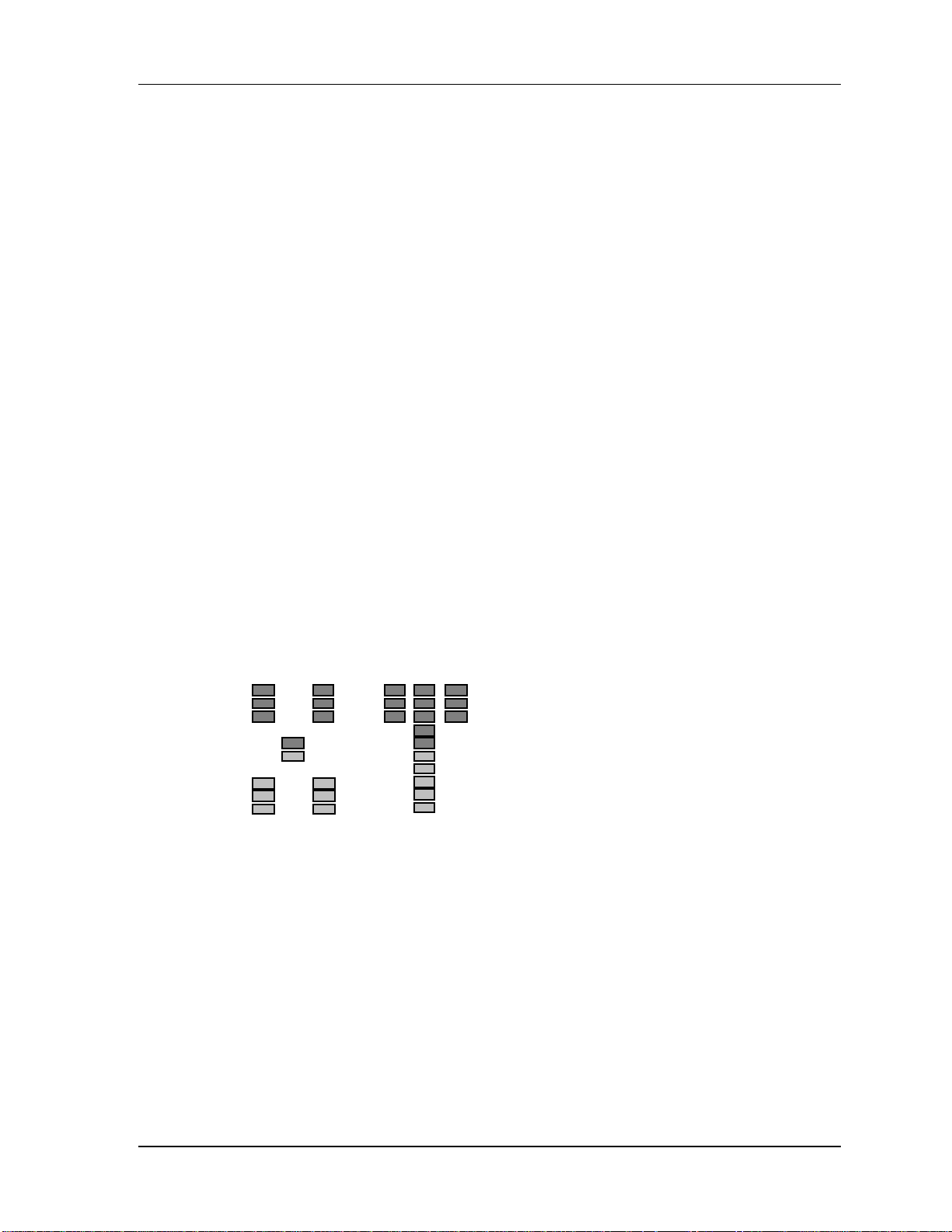
READING THE DISPLAY
The XT20’s display serves many functions. It shows the current level of each of
the eight audio tracks, it shows the current tape position numerically in hours,
minutes, seconds, and 100ths of seconds, and shows the current modes of the
many parameters available. It also is used as a window for editing parameters
such as pitch, track delay, tape offset, and locate points. With all segments lit
(which would not happen in normal operation), the display looks as follows:
MACH
When in a typical play situation, the display may look like this:
The meters show the current level of each playback track. Tracks 4 and 6 are
both in record (as indicated by the REC LEDs) and monitoring their inputs (as
indicated by the INPUT LEDs). The TIME counter (directly above the meters)
shows the current tape position, in this case relative to the user-defined
0:00:00.00 point (RELative Time). The display example above indicates that
the CLOCK is currently set to INTernal and 48KHz, the AUTO INPUT
MONitor is on, and the Analog input is selected. The icon indicates that a
tape is detected, and the LOCKED icon tells us that playback is engaged.
48 ADAT XT20 Reference Manual
Page 50

Basic Operations: Chapter 4
DISPLAY ICONS
The following icons appear in the display at different times. They
indicate that the parameter for which they are named has been
selected or turned on. These icons are:
FINE dB This icon lights whenever the meter resolution is in its
fine calibration mode, showing the range from -18 dBFS to -12.5 dBFS
instead of the normal 0 to -48 range. (Access this mode by pressing
PEAK MODE and PEAK CLEAR simultaneously.)
ABS This icon lights whenever Absolute Time mode is selected (by
pressing the [ABS/REL] button).
REL This icon lights whenever Relative Time mode is selected (by
pressing the [ABS/REL] button).
The PITCH group of icons relates information regarding pitch change.
Whenever the Pitch setting is above 0, the upper triangle will appear.
Whenever the Pitch setting is below 0, the lower triangle will appear.
When either PITCH buttons ([▲] or [▼]) are pressed, the PITCH icon
will appear indicating that the TIME counter is now displaying the
current Pitch setting using two values: Percentage (%) and Cents (C).
See page 62.
Indicates whether Format mode is turned on or off. The
FORMAT icon will flash whenever an unformatted tape is inserted. If
the [FORMAT] button is pressed, the FORMAT icon will light. If the
[FORMAT] button is pressed again, the FORMAT icon will turn off. See
page 35.
This icon will light when performing a format extend. See page
37.
This icon will light whenever a tape is inserted which has its
write-protect tab removed, indicating it cannot be recorded on. This,
however, can be overridden using the Protect Override function. See
page 39.
This icon will light whenever a tape is inserted.
ID If connected to a multiple ADAT system, the ID icon lights
when the XT20 is turned on. The number appearing to the right of the
ID icon will indicate the ID number of the unit (1–16). You can check
the unit’s ID without turning the unit on and off by holding [SET
LOCATE] and pressing [PLAY]. See chapter 5.
ADAT XT20 Reference Manual 49
Page 51

Chapter 4: Basic Operations
the [EDIT VALUE] button). See page 46.
When in Edit mode, this icon indicates that you are editing a Locate
Point’s address, which will appear in the TIME counter. A number (from
0 to 9) will appear next to the EDIT icon to indicate which Locate Point
is being edited. See page 46.
MACH. OFFSET This icon indicates that you have the Tape Offset
function turned on with a value that is not equal to 0:00:00.00. This
function is only available when the XT20 is used as a slave within a
multiple ADAT/XT20 system. When in Edit Mode, this icon indicates
that you are editing the Tape Offset amount, which will appear in the
TIME counter. See Chapter 5.
function turned on. When in Edit Mode, this icon indicates that you are
editing a tracks delay amount, which will appear in the TIME counter.
A number (from 1 to 8) will appear next to the EDIT icon to indicate
which track is being edited. The VU meters will also show a bar-graph
representation of the current delay values for all eight tracks. See page
63.
This icon will light whenever edit mode is selected (by pressing
Indicates that the transport is shuttling to a Locate Point (0–9).
This icon indicates that you have the Track Delay
When this icon appears, it indicates that the Auto Record
function has been turned on. See page 69.
This icon indicates that the Rehearse function is turned on. See
page 69.
This icon indicates that the Auto Play function is
turned on. See page 68.
This icon indicates that the Auto Return function is
turned on. See page 68.
When this icon appears, it indicates that the XT20 is slaving to
an external timecode source coming from the master ADAT in a multiple
ADAT system. See Chapter 5.
When this icon appears, it indicates that the transport is
properly engaged in either playback or recording. When the XT20 is a
slave in a multiple ADAT system, this icon will light to indicate that
the tape is properly synchronized and the audio is sample locked to the
timecode of the master ADAT machine. See Chapter 5.
50 ADAT XT20 Reference Manual
Page 52

Basic Operations: Chapter 4
The CLOCK group of icons indicates which clock source is being used.
The [CLOCK SELECT] button lets you toggle through the various
options, including: INT 48K (internal clock at 48kHz), INT 44.1K
(internal clock at 44.1 kHz) and DIG (external clock source connected to
the [DIGITAL IN] connector on the rear panel). Additionally, if the
XT20 is being used as a slave in a multi-ADAT system, the EXT icon
will light, indicating that the XT20 is deriving its clock from the
master ADAT in the system. See page 59.
The INPUT MON group includes two icons: ALL and AUTO. The ALL
icon will light whenever the All Input function is enabled (by pressing
the [ALL INPUT] button). The AUTO icon will light whenever the
Auto Input function is enabled (by pressing the [AUTO INPUT] button).
See page 50.
The INPUT group of icons indicates which input source is being used.
The ANALOG icon will light whenever the Analog Inputs are selected
(by pressing the [ANALOG INPUT] button). The DIGITAL icon will
light whenever the Digital Inputs are selected (by pressing the
[DIGITAL INPUT] button). The TRK COPY icon will light whenever
the Track Copy function is selected (by pressing the [TRACK COPY]
button). See pages 48 and 49.
This is the Interpolation Indicator. When it flashes, it indicates that
errors have been detected and corrected using an interpolation scheme.
It is a good idea to clean the tape heads and/or make a backup copy of
your tape if you ever see this icon light. See Appendix C for more
information.
16 BIT
20 BIT
This icon lights when there is a 16-bit (Type I) tape inserted in the
transport.
This icon lights when there is a 20-bit (Type II) tape inserted in the
transport.
ADAT XT20 Reference Manual 51
Page 53

Chapter 4: Basic Operations
52 ADAT XT20 Reference Manual
Page 54

Basic Operations: Chapter 4
TIME COUNTER & ABS/REL BUTTON
The TIME Counter (found at the top left section of the display) is used
to indicate the current tape position.
ABS
0H 15M 48S 21
The [ABS/REL] button toggles the TIME counter between Absolute Time
mode and Relative Time mode. The XT20 will indicate which Time
mode is selected by either displaying ABS (for Absolute Time) or REL
(for Relative Time) just to the left of the TIME counter.
REL
ABS Absolute Time: This is the XT20’s time reference, which is
created when a tape is formatted.
REL Relative Time: This is based on the XT20’s time reference of a
formatted tape, but is relative to where the tape was positioned when
LOCATE 0 was stored.
0H 01M 29S 03
✪
The Locate Points ‘ addresses are displayed in the format of the
display mode you’ve selected. They always refer to the same tape
position regardless of the display mode.
See the Autolocation section later in this chapter for more information
about the difference between ABS Time and Relative Time.
• When no tape is present the counter will display “-- -- --
--”.
• When an unformatted tape is played, the display will read
“noFo” and the FORMAT icon will flash.
The TIME counter (in either Absolute Time or Relative Time modes)
indicates time code in hours:minutes:seconds.100ths-of-seconds.
minutes seconds
0 : 03 : 28 : 15hours
100ths-of-seconds
LOCATE 0
Pressing the [LOCATE 0] button will take you either to the absolute
0:00:00.00 position (if ABS Time mode is selected) or to the relative
0:00:00.00 position (if Relative Time mode is selected). The Absolute
0:00:00.00 position never changes, since it is derived from the timecode
that was written onto tape during the formatting process. The Relative
0:00:00.00 position is user-definable.
You can set the Relative 0:00:00.00 position at any time by pressing the
[SET LOCATE] button followed by the [LOCATE 0] button. This
ADAT XT20 Reference Manual 53
Page 55

Chapter 4: Basic Operations
automatically switches the TIME counter to Relative Time mode (if not
already selected); the REL icon appears to the left of the TIME counter.
The counter will now read:
REL
0H 00M 00S 00
54 ADAT XT20 Reference Manual
Page 56

BASIC EDITING
Basic Operations: Chapter 4
EDIT V
The [EDIT VALUE] button is used to turn Edit mode on and off. When
turned on, the EDIT icon will light indicating you are now in Edit mode.
At this point, you can press any one of the [LOCATE 0] - [LOCATE 9],
[TAPE OFFSET] or [TRACK DELAY] Function buttons to view and/or
edit their respective parameter settings in the display. The icons just
below the EDIT icon in the display will indicate which feature is
currently selected for editing (when in Edit mode), and which features
are on or off (when not in Edit mode). When Edit mode is selected, the
TIME counter provides a display of the selected parameter’s current
setting.
The first time [EDIT VALUE] is pressed, Locate 0 will be selected.
While the EDIT icon is still on, you can press another Function button to
access its parameter(s). Press [EDIT VALUE] again to exit Edit mode;
the EDIT icon will turn off. Pressing a Function button now will toggle
that function on or off. The next time Edit mode is turned on, the display
will return to the last function you were editing before exiting Edit
mode.
Function Button When Edit Mode is on... When Edit Mode is off...
[LOCATE
0]–[LOCATE 9]
[TAPE OFFSET]
[TRACK DELAY]
ALUE BUTTON
Edit Locate Point address Execute a locate
Edit Tape Offset amount Tape Offset on/off
Edit Track Delay settings Track Delay on/off
▲ AND ▼ BUTTONS
Once a function is selected, the ▲ and ▼ buttons are used to increment or
decrement its setting by single values. By holding either button, the
increment or decrement value increases its speed. By simultaneously
pressing both buttons, the selected parameter is reset to 0.
ENTERING NUMERIC VALUES
If [EDIT VALUE] is held while in Edit mode, you may use the
[LOCATE 0] – [LOCATE 9] buttons as a 10-digit keypad (from 0 to 9)
to enter a specific numerical value for the currently selected parameter
in the display. Numbers are entered from left to right.
Examples: If [LOCATE 1] is pressed using this method to edit Track
Delay time (displayed as XXX.X ms), the display would show .1 ms. If
a [LOCATE 5] is now entered, the display shows 1.5 ms. If the [EDIT
VALUE] button is released at this time, the display shows 001.5 ms
and that would be the new Track Delay value. Likewise, if this
method is used to edit a Locate Point (X:XX:XX.XX) and the sequence of
numbers were entered as follows: [LOCATE 1] – [LOCATE 2] –
[LOCATE 3] , the display would successively show . 1, .12, 1.23. If
the [EDIT VALUE] button is then released, the display would show
0:00:01.23 and that would be the Locate Point’s value.
ADAT XT20 Reference Manual 55
Page 57

Chapter 4: Basic Operations
EDITING INDIVIDUAL DIGITS
You can also select a specific digit in the display to edit, by holding the
[EDIT VALUE] button and pressing either [▲] or [▼]; the currently
selected digit will flash. While still holding the [EDIT VALUE]
button you may press any of the [LOCATE 0] – [LOCATE 9] buttons to
enter a specific numerical value for the currently selected digit. The
selected digit will replace the previous once and will stop flashing,
and the next digit to its right will be selected (flashing) so you may
continue entering digits using the [LOCATE 0] – [LOCATE 9] buttons.
56 ADAT XT20 Reference Manual
Page 58

Basic Operations: Chapter 4
INPUT SELECT
There are three buttons for input select options. These three buttons are labeled
[ANALOG INPUT], [DIGITAL INPUT], and [TRACK COPY]. These
determine what signals will be recorded on the XT20. The currently selected
input mode is indicated in the lower right corner of the display: ANALOG,
DIGITAL or TRK COPY.
While any of the Input Select buttons are being held, the channel record and
input status indicators no longer indicate the current record or input status, and
the REC icon turns off. As long as one of these buttons is being held, the tracks’
INPUT LED is used to indicate channel selection for that particular function,
and the RECORD ENABLE buttons [1] – [8] are used to select and de-select
channels (see page 54).
ANALOG INPUT
Pressing the [ANALOG INPUT] button once selects the analog inputs
(both unbalanced and balanced) for recording and monitoring; the
ANALOG icon will light in the INPUT icon group in the display.
While holding the [ANALOG INPUT] button, the channel input
indicators will show the number of analog inputs that are currently
selected. There are three selections possible: Two inputs, four inputs, or
eight inputs. This allows you to record from a 2 or 4 bus mixing console
without repatching.
• To choose 2-input mode: Press either the channel 1 or 2
RECORD ENABLE buttons while holding [ANALOG INPUT]. This
will cause both the channel 1 and 2 input lights to light up, indicating
that only input channels 1 and 2 will be used. If any of tracks 1, 3, 5, or 7
are record enabled, they will receive their input signal from the analog
input of channel 1. If any of tracks 2, 4, 6, or 8 are record enabled, they
will receive their input signal from the analog input of channel 2.
• To choose 4-input mode: Press RECORD ENABLE button 3 or 4
while holding the [ANALOG INPUT] button. This will cause channels
1 through 4 INPUT LEDs to light up, indicating that only input
channels 1 thru 4 will be used. In this case, channels 5 through 8 receive
their input from channels 1 through 4, respectively.
• To choose 8-input (the most common) mode: Press RECORD
ENABLE button 5 thru 8 while holding the [ANALOG INPUT] button.
This will cause all eight track INPUT LEDs to light. In this mode,
each track receives its signal from its own input.
✪
ADAT XT20 Reference Manual 57
Page 59

Chapter 4: Basic Operations
In 2-input mode, inputs 3-8 are disconnected and cannot be recorded or
heard. In 4-input mode, inputs 5-8 are similarly disconnected. To use all
inputs, 8-input mode must be selected.
DIGITAL INPUT
To record from the digital input, press the [DIGITAL INPUT] button;
the DIGITAL icon in the INPUT icon group will light. The digital
input can be used to record from another XT20 or ADAT-compatible
optical signal. All eight channels will be received via the fiber optic
connection (see Digital In/Out in Chapter 3) and the analog inputs will
be ignored. However, by holding the [DIGITAL INPUT] button, you
may reroute incoming channels to record on different tracks; Example:
Digital audio received on channels 1 and 2 can be rerouted and recorded
onto tracks 3 and 4. For more information about recording from the
digital input and digital track bouncing, see chapter 5.
TRACK COPY
The [TRACK COPY] button is used to digitally bounce tracks within a
single XT20. To digitally bounce tracks, you must first press [TRACK
COPY]; the TRK COPY icon in the INPUT icon group will light.
Next, select the source tracks, select (record enable) the destination
tracks, and initiate recording. The track copies will be an exact
duplicate of the original (i.e. it is exactly aligned with the original
and is an exact clone).
While holding the [TRACK COPY] button, the track’s INPUT LEDs
will indicate the selected source channel(s). While still holding the
[TRACK COPY] button, the source tracks may be selected and deselected by pressing the RECORD ENABLE buttons [1] – [8]. Releasing
the [TRACK COPY] button will return the channel REC and INPUT
indicators and RECORD ENABLE buttons to their normal status. At
this point, you may record-enable the destination tracks (see next
section).
When copying tracks:
• The source tracks will be recorded onto the destination tracks in
ascending order. Example: If source tracks 1 and 3 are selected and
tracks 5 and 6 are record enabled, then track 1 will be copied to track 5
and track 3 to track 6.
• If more destination tracks are selected than source tracks, the
source tracks will repeat (cycle). Example: If tracks 7 and 8 were added
to the destination tracks of the previous example, then track 1 would be
copied to tracks 5 and 7 and track 3 would be copied to tracks 6 and 8.
This scheme also allows for copying a single track to multiple tracks.
• Since no more than 4 tracks may be copied within a single
machine, a maximum of 4 source tracks will be allowed. This means
that if 4 source tracks are already selected, then no other tracks can be
selected until one of the 4 tracks is de-selected.
58 ADAT XT20 Reference Manual
Page 60

Basic Operations: Chapter 4
• A digital source track cannot be selected as a digital
destination track (i.e. digital source tracks will not be allowed to be
record enabled when Track Copy is enabled).
• If no source tracks are selected, you will not be able to place any
tracks into record-ready. If user attempt to record enable a track, the
track will not be enabled (REC LED will not light) and “noSovrcE”
will be temporarily displayed in the TIME counter.
• When Track Copy mode is enabled (TRK COPY icon lit), the
All Input Monitor will not function. If the All Input Monitor is on when
Track Copy is enabled, it will automatically be turned off (ALL icon in
the INPUT MON icon group will turn off). See the next page for more
information about the All Input Monitor.
• Any track delays that you have programmed will be in effect.
ADAT XT20 Reference Manual 59
Page 61

Chapter 4: Basic Operations
INPUT MONITOR
The Input Monitor controls consist of two buttons: [ALL INPUT] and [AUTO
INPUT].
AUTO INPUT MONITOR
This feature determines what you will hear from the XT20’s output
jacks when a track is record-enabled (REC LED flashing): tape, or
source. The [AUTO INPUT] button toggles the Auto Input Monitor on
and off. When a track is monitoring its input signal, its INPUT LED
will be lit.
• When the Auto Input Monitor is off (AUTO icon in the INPUT
MON icon group is off), all record-enabled tracks will monitor the input
signal and all other tracks will monitor the taped signal.
• When the Auto Input Monitor is on (AUTO icon is lit), it allows
input monitoring of record enabled tracks while in record, stop, rewind
or fast fwd; but not in play.
The reason for having these two options is to accommodate different
stages of the recording process. Leaving the Auto Input Monitor off is
the “normal” option and is what you would use when first recording
tracks. When performing punch-ins and overdubs, you will probably
want to turn the Auto Input Monitor on so that you can hear what was
recorded on tape for a given track right up to the point you want to
punch in. As soon as the XT20 punches into record mode, the tape signal
is replaced by the input signal so you can hear what’s being recorded to
tape. After you punch-out, the monitor reverts to tape.
Typically, Auto Input should be on when the Rehearse feature is used
(see page 69).
ALL INPUT MONITOR
When the [ALL INPUT] button is on (ALL icon in the INPUT MON icon
group is lit), the Auto Input Monitor setting is overridden so that all
tracks monitor their input signals regardless of their record enable
status. All eight track INPUT LEDs will be lit. When All Input
Monitor is off (ALL icon is off), the Auto Input Monitor setting
determines track monitoring.
The All Input Monitor will automatically be turned off if Track Copy
mode is enabled (by pressing the [TRACK COPY] button (see previous
page).
The following table indicates the status of tracks that are recordenabled and tracks that are not depending on the status of the [AUTO
INPUT] and [ALL INPUT] buttons.
60 ADAT XT20 Reference Manual
Page 62

Basic Operations: Chapter 4
Record-enabled tracks = ■ ; Tracks not record-enabled = ❑
Transport
Function
Stop,Pause,
Rew.,F.Fwd
Play
Record
Auto = Off
All = Off
■ = Input
❑ = Tape
■ = Input
❑ = Tape
■ = Input
❑ = Tape
Auto = On
All = Off
■ = Input
❑ = Tape
■ = Tape
❑ = Tape
■ = Input
❑ = Tape
Auto = Off/On
All = On
■ = Input
❑ = Input
■ = Input
❑ = Input
■ = Input
❑ = Input
ADAT XT20 Reference Manual 61
Page 63

Chapter 4: Basic Operations
METERS
The XT20 provides two buttons for meter display options: [PEAK MODE] and
[PEAK CLEAR].
PEAK MODE BUTTON
The [PEAK MODE] button selects the peak hold mode of the eight
level meters. Each time the [PEAK MODE] button is pressed, the peak
meters switch between three possible Peak Hold modes: Continuous,
Momentary and Off. The currently selected mode may be determined by
observing the peak meters themselves.
• Continuous: Each track’s peak LED indicator will remain lit,
until the [PEAK CLEAR] button is pressed, or the Peak Mode is
changed.
• Momentary: Each track’s peak LED indicator will remain lit
for about two seconds.
• Off: No peak indicators will be held on any tracks.
PEAK CLEAR BUTTON
The [PEAK CLEAR] button is used to remove any track peak LED
indicators which remain lit while either Continuous or Momentary
Peak Mode is selected (see above). This button will have no effect if the
Peak Mode is turned Off.
FINE METER MODE
The XT20 provides a special mode which rescales the peak meters for
more specific readings. This is necessary when making very fine level
adjustments, such as when recording test tones. When Fine Meter mode
is enabled, the meters are rescaled around a center point of -15 dB
(middle point of the meters) and goes plus and minus from there in .5 dB
increments. This means the -15 dB icon will be the only level marking
that is correct in this mode. The meters’ actual range will be from -18.0
dB to -12.5 dB. However, the MAX icon at the top of each meter will
still indicate clipping.
To activate Fine Meter mode:
❿ Simultaneously press both [PEAK MODE] and [PEAK CLEAR]
buttons.
The TIME counter will momentarily display “FinE db” and the dB
stepped markings will appear on the left side of the meters. The
FINE dB icon will turn on.
❡ To exit Fine Meter mode, press either [PEAK MODE] or [PEAK
CLEAR].
The dB stepped markings and icon will turn off.
62 ADAT XT20 Reference Manual
Page 64

Basic Operations: Chapter 4
Note: The Peak Hold function is disabled (off) when Fine Meter mode is
enabled.
ADAT XT20 Reference Manual 63
Page 65

Chapter 4: Basic Operations
RECORDING A “BENCHMARK” TAPE
We recommend that you format and record a new tape with any signal, such as
a test tone, in a single pass with no overdubs during the first week of operation.
Store this tape in a safe, dry location and don’t use it for any other purpose.
Such a “benchmark” tape is useful to determine if the error correction rate is
increasing over time because the heads need to be cleaned, or if a tape is
defective (see page 100).
64 ADAT XT20 Reference Manual
Page 66

Basic Operations: Chapter 4
RECORD ENABLE
To record enable a track, press the track’s RECORD ENABLE button.
When you press a track’s RECORD ENABLE button for the first time, the
track’s red REC LED will flash, indicating the track is in record-ready, and its
INPUT LED will light (unless Auto Input is on and the transport is in play),
indicating you will be able to monitor that track’s input. If the transport is put
into record mode (see Transport Controls in this chapter), recording will begin
on this track; the track’s REC LED will stop flashing and remain lit. To disable
record-ready, press the track’s RECORD ENABLE button once again. The
track’s REC LED will turn off.
RECORD ENABLE buttons can be turned on or off while you are in record mode.
SETTING LEVELS
Unlike analog tape recorders, where signals routinely exceed 0 dB with no
apparent ill effects, 0 dB on the XT20 represents the maximum possible signal
level. Signals above 0 dB will be clipped and lead to digital distortion.
Because of the limitations of analog tape, there was always a tradeoff between
noise, level and distortion. More level improved the signal-to-noise ratio, but
also increased distortion. This distortion increased linearly, which is why
signal-to-noise was often specified for a certain amount of distortion (typically
3%). You could always record with hotter levels or softer levels, but either
more distortion or more noise would result—with analog, you couldn’t have low
noise, high levels and low distortion.
With digital recording, there is a much wider dynamic range, and distortion
does not increase with increasing level. Yet once a digital system runs out of
headroom and hits 0 dB, that’s it—the onset of distortion is immediate and
very noticeable if the signal is sustained several dB above the limit. Even
though very short peaks above 0 may not last long enough to cause audible
distortion, you aren't capturing the signal in its original form. As a result,
because of the XT20’s signal to noise characteristics, it’s better to err on the side
of setting levels not quite high enough rather than having them distort,
especially during live recording when you don’t get a second chance. In the
studio, where you have more control over levels or are using compressor/
limiters, it’s OK to light up the MAX LED on the meter on the very loudest
peaks, as long as you're sure that signals aren't going beyond that point (by
using the meters on your console, if they go beyond +15 dB).
However, since 0 dB on the XT20 equals the maximum level, the input reference
level is set below 0 VU. With the XT20, a 0 VU signal on a +4 dBu mixer
plugged into the XT20’s +4 dBu connectors (or a 0 VU signal on a -10 dBV mixer
plugged into the XT20’s -10 dBV connectors) will register -15 dB (the first green
segment) on the XT20’s meters. Therefore, you can run the mixer over 0 VU and
ADAT XT20 Reference Manual 65
Page 67

Chapter 4: Basic Operations
still have 15 dB of headroom on the XT20 before distortion occurs. Just remember
that no matter what, if the XT20’s meters indicate over 0 dB, distortion is
occurring or is on the verge of occurring.
✪
Be sure the outputs of your mixer match the inputs connected to the XT20 (+4 or -
10).
66 ADAT XT20 Reference Manual
Page 68

Basic Operations: Chapter 4
TRANSPORT CONTROLS
The XT20’s six transport control buttons resemble those of a conventional tape
recorder, although there are several extra features.
EJECT
Press the [EJECT] button to eject the tape from the XT20. If the tape is
moving, it will stop before ejecting. In a multiple XT20 system where
there is one master and one or more slave XT20s and/or ADATs, pressing
[EJECT] on the master will eject the tapes on all machines; pressing
[EJECT] on a slave machine will only eject the tape on that machine.
✪
The [EJECT] button will not operate while recording or formatting to
avoid interrupting these processes.
REWIND/REVIEW
Press the [REWIND] button to rewind the tape; the [REWIND] LED
lights. When fully rewound, the [REWIND] LED turns off and the
[STOP] LED lights.
• Pressing [REWIND] while recording punches out before
rewinding.
• Threaded tapes rewind at about 40 times normal play speed.
Unthreaded tapes rewind slightly faster.
• Pressing [REWIND] while holding the [PLAY] button initiates
“Review” mode. The tape rewinds at about 3 times normal play speed,
and you can hear chunks of attenuated audio so you know where you are
on the tape. The [PLAY] LED will be lit, and the [REWIND] LED will
be flashing. Pressing the [PLAY] button alone returns the transport to
normal play mode.
FAST FORWARD/CUE
Press the [FAST FWD] button to fast forward the tape; the
[FAST FWD] LED lights. Upon reaching the tape’s end, the
[FAST FWD] LED turns off, and the [STOP] LED lights.
• Pressing [FAST FWD] while recording punches out before fast
forwarding.
• Threaded tapes fast forward at about 40 times normal play
speed. Unthreaded tapes fast forward slightly faster.
ADAT XT20 Reference Manual 67
Page 69

Chapter 4: Basic Operations
• Pressing [FAST FWD] while holding the [PLAY] button
initiates “Cue” mode. The tape fast forwards at about 3 times normal
play speed, and you can hear chunks of attenuated audio so you know
where you are on the tape. The [PLAY] LED will be lit, and the
[FAST FWD] LED will be flashing. Pressing the [PLAY] button alone
returns the transport to normal play mode.
68 ADAT XT20 Reference Manual
Page 70

Basic Operations: Chapter 4
PLAY
Press the [PLAY] button to play the tape ([PLAY] LED will light). The
[PLAY] button by itself has no effect while playing, but it will
terminate recording. While locating, pressing [PLAY] will cause the
XT20 to start playing after it arrives at the corresponding tape location
([PLAY] LED will flash to indicate deferred play mode).
Pressing [PLAY] while recording causes the XT20 to punch out (recording
stops and playback continues). Pressing [PLAY] in any mode other than
locating causes the transport to enter play mode, and the [PLAY] LED
lights.
✪
What occurs when you press [PLAY] after inserting a tape in the XT20
depends on whether the tape being played is formatted or not.
• Formatted. The tape plays normally and the tape counter
shows elapsed time since the beginning of the tape.
• Unformatted tape. The XT20 will detect the lack of a format
and flash the FORMAT icon while reading “noFO” in the TIME
counter.
• Tape transitions from a formatted to unformatted section while
playing back. The XT20 will detect the lack of a format and flash the
FORMAT icon while reading “noFO” in the TIME counter.
• Tape transitions from a formatted to unformatted section while
recording. The XT20 will detect the lack of a format and stop.
RECORD/PUNCH IN OR OUT
Use the [RECORD] button to enter or exit record mode, and to format a
tape. There are two methods of entering record mode. You can first
enable the tracks you wish to record on and then engage recording using
the [PLAY] and [RECORD] buttons. Or you can engage record mode and
then use the RECORD ENABLE buttons to place tracks in or out of
record. If no tracks are enabled for recording and record mode is engaged,
the [RECORD] LED will flash to indicate that pressing any RECORD
ENABLE button will immediately initiate recording on that track.
To start recording:
• Hold [PLAY] and press [RECORD] to cause any record-enabled
track to enter record mode. This is recommended for punching “on the
fly.”
• Hold [RECORD] and press [PLAY] to cause any record-enabled
track to enter record mode. This is recommended for initiating recording
when the tape is stopped, or for punching “on the fly.”
To punch out and stop the transport, simply press [STOP]. There are
three ways to exit record mode (punch out) yet have the transport
continue to play; use whichever method is most natural to you.
ADAT XT20 Reference Manual 69
Page 71

Chapter 4: Basic Operations
• Press [PLAY].
• Hold [RECORD] , and then press [PLAY].
• Use the RECORD ENABLE buttons [1] – [8] to take tracks out of
record.
STOP
The [STOP] button performs three functions.
• Stop the transport. Push [STOP] to stop any function involving
tape motion. A lit [STOP] LED indicates that the tape is not moving
and is threaded. A flashing [STOP] LED indicates that the tape is not
moving and is unthreaded.
• Thread/Unthread the tape. While the [STOP] LED is lit,
press [STOP] to unthread the tape ([STOP] LED flashes). While the
[STOP] LED is flashing, press [STOP] to thread the tape ([STOP]
LED is lit). Entering play or record more will also thread the tape, if it
was previously unthreaded.
• Punch out. When recording, pressing [STOP] will exit record
mode and stop the transport.
SAMPLE RATE (CLOCK)
The XT20 records digital audio in a similar manner as a DAT recorder or digital
sampler. You may select between two sample rates when using the XT20’s
internal clock: 48 kHz and 44.1 kHz. Set the sample rate to match the rest of
the recording system (digital mixers, DAT recorders, CD players) you are
digitally connected to.
The currently selected sample rate is indicated by the CLOCK group of icons in
the display. When the INT and 44.1K icons are lit, the XT20 is set to an
internal 44.1 kHz clock. When the INT and 48K icons are lit, the internal 48
kHz clock setting is in use. The default setting is internal 48 kHz (INT 48K).
✪
Changing the clock from 48kHz to 44.1 kHz, or vice-versa, will change the
reference point upon which the Pitch controls are based. This will also cause
the TIME counter to change; the Locate Points (see page 67) will be referenced to
different time positions (when viewed), although they still correspond to the
same physical tape positions as before.
To select the sample rate:
❿ Press the [CLOCK SELECT] button.
Each time the [CLOCK SELECT] button is pressed, the right side of the
display will cycle through the following settings: INT 48K, INT 44.1K, DIG
48K, and DIG 44.1K.
For more info on DIG and EXT clock settings, see chapter 5. It is recommended
that you select the sample rate you want to use before you format a tape. During
70 ADAT XT20 Reference Manual
Page 72

Basic Operations: Chapter 4
the formatting process, the sample rate information is written onto the tape.
This information allows the XT20 to know what sample rate the tape was
originally formatted at. When inserting a tape that was formatted at 48 kHz,
the XT20 reads the timecode from tape for a moment and automatically selects
the 48 kHz clock setting. If the clock is then manually changed to 44 .1 kHz, the
44.1K icon will flash, to indicate that you are using 44.1 kHz but it isn’t the
original sample rate used when the tape was formatted. The same goes when
you play a tape formatted using 44.1 kHz with the clock set to 48 kHz; the 48K
icon will flash.
If you play back a tape that was formatted on an original ADAT, it will not
have any sample rate information written on it (since this is a new feature not
found on the ADAT). In this case, the XT20 will assume the tape was formatted
at 48 kHz. Therefore, if you had been pitching-down such a tape on an ADAT to
play at 44.1 kHz, you must press the [CLOCK SELECT] button to manually
change the clock to 44.1 kHz.
RECORD CROSSFADE TIME
Crossfading is the process of fading out the original audio on tape while fading
in the new audio when punching in (or vice-versa when punching out).
Whenever recording begins or ends, the XT20 provides a smooth transition
between the audio on tape and the audio being recorded. This prevents gaps
and/or noises when punching in and out of record.
The Record Crossfade Time setting determines how long it takes for the audio to
completely transition from the previous audio to the current audio when
recording. The default is 11 milliseconds but can be increased to 43 ms. The
faster crossfade time allows you to punch in and out quicker, and is best used
when the audio on tape is similar to the audio you are recording. The longer
crossfade time allows for a smoother transition and is more useful when
punching in new material that is very different from what is already on tape,
or when punching in low-frequency signals. Crossfading always begins at the
punch point and continues for the amount of time you have specified.
To set the Crossfade Time:
❿ Press and hold the [SET LOCATE] button.
❡ While holding the [SET LOCATE] button, press the [RECORD]
button. This will advance Crossfade setting to its next value, in this case it is 21
ms. The TIME counter will briefly read:
FA dE 2@ 1
① While still holding [SET LOCATE], each time you press [RECORD]
will advance the Crossfade setting to the next value. Select either 11 ms, 21 ms,
32 ms and 43 ms. These time values assume a playback rate of 48kHz, and are
therefore not exact if the Pitch amount is changed, or an external clock source is
used. If the Clock is set to 44.1 kHz, the available crossfade times are actually
12 ms, 23 ms, 35 ms and 46 ms (although they will not be labeled this way). To
select the sample rate (48 kHz or 44.1 kHz), see previous section.
DISPLAYING FRAMES VS. 100THS/SECONDS
If you are using the XT20 with the BRC, you will notice that the BRC’s TIME
display uses the “hours:minutes:seconds:frames” format, while the XT20
ADAT XT20 Reference Manual 71
Page 73

Chapter 4: Basic Operations
normally uses the “hours:minutes:seconds:100ths/second” format. This may
cause some confusion when locating to a specific position on the BRC, since the
XT20 will show a slightly different value when looking at the last two digits
of the TIME counter. The XT20 will locate to the same physical position that
the BRC displays, it is simply displaying 100ths/second instead of frames.
It is possible, however, to switch the XT20’s TIME display so that it counts in a
30 FPS format, instead of 100ths/second. This is done by holding [SET
LOCATE] and pressing RECORD ENABLE [4]. Repeat this process to toggle
back and forth between these two modes. When set to “frames-per-second”
mode, the TIME counter will briefly read “d1SP FPS”. When switched back
to “100ths-of-a-second” mode, the TIME counter will briefly read “d1SP
rE”. This feature is designed for the sole purpose of aligning the displays of
the XT20 and the BRC. The selected mode also affects how the Locate Points
are displayed and edited on the XT20.
72 ADAT XT20 Reference Manual
Page 74

Basic Operations: Chapter 4
PITCH CONTROL
The Pitch function controls the speed of the tape, and thus the pitch of the
audio recorded on tape. It displays speed as percentage and as cents. A cent is
1/100th of a semitone. For example, if a song is originally recorded in the key of
C, then played back with the pitch raised 100 cents, it will be in the key of C#.
The XT20’s Pitch control has a range of -300 to +100 cents when using a sample
rate of 48 kHz, and a range of -200 to +200 when using 44.1 kHz. The Pitch
controls will not function while locking to an external clock (i.e. while the XT20
is slaved to another ADAT or is locking to an external digital clock).
The PITCH [▲] and [▼] buttons control the amount of pitch change. When
either button is pressed once, the PITCH icon lights in the display, and the
TIME counter immediately displays the current amount of Pitch change. The
Pitch amount is displayed both as a percentage (%) and as cents. After a few
seconds, the TIME counter reverts back to its normal mode.
ABS
To set the Pitch amount:
00
(Percentage) / (Cents)
00% 00. 00
.
C
❿ If Edit mode is currently on (EDIT icon lit), press [EDIT VALUE] to exit
Edit mode.
The EDIT icon should be off.
❡ Press and hold either PITCH [▲] or [▼].
After holding for more than .5 seconds, the Pitch amount will start either
increasing or decreasing, depending on which button was pressed.
① To immediately set the Pitch amount to +100, hold [SET LOCATE] and
press [▲].
➃ To immediately set the Pitch amount to -300, hold [SET LOCATE] and
press [▼].
➄ To reset the Pitch amount to 0, simultaneously press both [▲] and [▼].
Note: This is not possible while recording.
ABOUT PITCH CHANGING
Here are a few things to consider when chaning the XT20’s pitch:
• One of the PITCH arrow icons will remain lit in the display to
remind you that the pitch has been changed from standard pitch.
• The counter will not elapse in real time when the pitch is set to
a value other than zero.
• When you change the pitch on ADAT-XT20, the sampling rate
will also change. The lowest sampling rate is 40.4 kHz, the highest is
50.8 kHz.
• If the internal clock is set to 48 kHz, but the pitch is lowered 147 cents, the sampling rate is 44.1 kHz. However, for accurate TIME
ADAT XT20 Reference Manual 73
Page 75

Chapter 4: Basic Operations
counter display it is better to set the pitch to 0 and change the clock
rate (see page 59).
74 ADAT XT20 Reference Manual
Page 76

Basic Operations: Chapter 4
TRACK DELAY
Track Delay lets you delay individual tracks up to 170 ms, in order to achieve a
more desirable “feel.” For example, if the bass track is anticipating the beat,
you can push it back so it’s “in the pocket” by delaying it a few milliseconds. If
you need one track to play back earlier than the others, try offsetting all other
tracks by the same amount. This will make the remaining track appear to be
playing ahead of the others.
Track Delay times are set individually per track (or for a group of tracks) in the
Track Delay Edit page. Track Delay for all eight tracks may be turned on and
off without altering the Track Delay settings of each track.
To turn Track Delay on and off:
❿ If Edit mode is currently on (EDIT icon lit), press [EDIT VALUE] to exit
Edit mode.
The EDIT icon should be off.
❡ Press the [TRACK DELAY] button.
The TRACK DELAY icon will light, indicating that Track Delay values are in
effect.
① Press [TRACK DELAY] again.
The TRACK DELAY icon will turn off, indicating that Track Delay values are
disabled.
To set the Track Delay amount:
❿ Press [EDIT VALUE], to turn on Edit mode.
The EDIT icon will light.
❡ Press [TRACK DELAY].
The TRACK DELAY icon will light (if not already turned on).
① Press one of the eight RECORD ENABLE buttons [1]–[8].
The selected track’s REC LED will light and the display will indicate the
current Track Delay amount for the selected track. Press a different RECORD
ENABLE button to select another track (1–8) to edit.
ABS
1 10. 3 mS
➃ Use the [▲] and [▼] buttons to adjust the amount of delay for the
selected track.
➄ Alternatively, you may select a specific digit by holding [EDIT
VALUE] and using the [▲] and [▼] buttons.
The selected digit will flash.
➅ While holding [EDIT VALUE], press any [LOCATE] button to enter a
value.
The next digit to the right is automatically selected, so that you may continue
entering digits in this way. Releasing the [EDIT VALUE] button deselects the
digit, and the selected digit will stop flashing.
➆ To reset the Track Delay time to 000.0 ms, press both the [▲] and [▼]
buttons simultaneously; or, hold [EDIT VALUE] and press [LOCATE 0] .
♠ Repeat steps ① through ➆ to edit the Track Delay times of any other
tracks.
To set multiple tracks to the same Track Delay value:
If you need to “advance” a single track, you can set all other tracks to the same
delay value by selecting multiple tracks in step ① above. Simply press and
ADAT XT20 Reference Manual 75
Page 77

Chapter 4: Basic Operations
hold one RECORD ENABLE button while pressing others you wish to adjust to
the same amount, then proceed with steps ➃ through ➆.
76 ADAT XT20 Reference Manual
Page 78

Basic Operations: Chapter 4
AUTOLOCATION CONTROLS
The XT20’s autolocation controls consist of 10 Locate Point memories which can
be set either manually or “on the fly”, and recalled instantly.
✪
Each Locate Point’s address can be displayed and set using either Absolute or
Relative Time.
Generally, Absolute Time and Relative Time will differ in their values. The
XT20, however, maintains a constant offset between them. This makes it
possible to locate to various tape positions using either time reference.
ABSOLUTE (ABS) TIME VS. RELATIVE TIME
The TIME counter indicates where you are on the tape by using a time
reference. There are two ways of displaying the time reference off tape:
Absolute (ABS), the actual time reference, or Relative, the same time
reference but relative to a different zero point. The Relative Time
0:00:00.00 point is set by holding the [SET LOCATE] button and
pressing [LOCATE 0], or by editing the Locate 0 point.
Use the [ABS/REL] button to select between Absolute Time and
Relative Time modes; one of two icons (ABS or REL) will appear to the
left of the TIME counter. When the display is in Absolute Time Mode
(ABS icon lit), the display reflects the actual tape time. When in
Relative Mode (REL icon lit), the display reflects the tape’s time
reference relative to the 0:00:00.00 position. Once you hold the [SET
LOCATE] button and press [LOCATE 0] to establish a new 0:00:00.00
position on tape (see below), Absolute and Relative times will be offset
from one another. However, that offset will remain constant until the
next time the relative zero position is reset.
LOCATE 0
If the [LOCATE 0] button is pressed, the transport will immediately
begin locating to the 0:00:00.00 time location of the tape. If the TIME
counter is in ABS mode when [LOCATE 0] is pressed, the absolute
0:00:00.00 position is located. If the TIME counter is in Relative mode
when [LOCATE 0] is pressed, then the relative 0:00:00.00 position is
located. [LOCATE 0] is different from the other [LOCATE] buttons in
this respect: it may wind the tape to different locations, depending
whether the TIME counter is in ABS or REL mode. All the other locate
ADAT XT20 Reference Manual 77
Page 79

Chapter 4: Basic Operations
points represent the same actual (physical) position on tape, regardless
of whether the display is in ABS or REL mode.
The [LOCATE 0] button is also used to set the relative zero time.
When this button is pressed while holding [SET LOCATE], the
relative tape counter is reset to zero (0:00:00.00). Once this occurs, you
have changed the Relative Time zero point, and the display will
automatically change to Relative Time mode (REL icon lit).
78 ADAT XT20 Reference Manual
Page 80

Basic Operations: Chapter 4
SETTING LOCATE POINTS
There are two ways of storing Locate Point memories: manually or “on
the fly.”
To store a Locate Point memory “on the fly”:
❿ Press [PLAY] to engage playback.
Alternatively, the transport may be engaged in either Rewind,
Review, Fast Forward, Cue, Record or Stop mode (i.e. the transport does
not have to be in Play mode to store Locate Points in the following
manner; it is simply the most practical way to do it).
❡ Press and/or hold the [SET LOCATE] button.
The LOCATE icon will light and a dash (– ) will begin flashing to its
right.
① Immediately press one of the [LOCATE 0] – [LOCATE 9]
buttons.
The current tape location will be stored into the Locate Point memory
you selected. If [LOCATE] button is not pressed within 2 seconds after
releasing [SET LOCATE], the flashing dash will disappear and none
of the Locate Point memories will be changed.
➃ To store multiple Locate Points, you may continue holding the
[SET LOCATE] button and press any of the [LOCATE] buttons when
the desired tape positions are reached.
To edit a Locate Point memory:
❿ Press [EDIT VALUE] to enter Edit mode.
The EDIT icon will light.
❡ Press one of the [LOCATE 0] – [LOCATE 9] buttons to select a
Locate Point address.
The LOCATE icon will light, the selected Locate Point’s number (0-9)
will appear next to it, and the address of the selected Locate Point will
be displayed in the TIME counter.
① Use [▲] and [▼] buttons to fine tune the Locate Point’s address.
➃ Alternatively, you may select a specific digit by holding [EDIT
VALUE] and using the [▲] and [▼] buttons.
The selected digit will flash.
➄ While still holding [EDIT VALUE], press any of the [LOCATE
0] – [LOCATE 9] buttons to replace the selected digit with.
The next digit to the right is automatically selected, so you may
continue entering digits.
LOCATING
Once you have stored one or more tape positions into the Locate Point
memories, pressing any of the [LOCATE 0] – [LOCATE 9] buttons
while Edit mode is not selected will initiate a locate to its respective
address. The TIME counter will momentarily display the selected
Locate Point’s address and the Locate Point’s number (0–9) will appear
in the upper-right corner of the display; the transport will either fast
forward or rewind to the selected Locate Point’s address.
ADAT XT20 Reference Manual 79
Page 81

Chapter 4: Basic Operations
AUTO LOOPING
Auto Looping is not a feature in and of itself, but is made up of two important
features that, when used together, provide a very useful tool. These two
features are: Auto Return and Auto Play. When both are enabled, and set
correctly, a section of tape of any length may be continuously repeated.
AUTO RETURN
When Auto Return is enabled, and the transport reaches the Locate 4
point (the end of the loop), it will automatically rewind to the Locate 1
point (the start of the loop). Notice the arrow on the front panel
connecting the [LOCATE 1] and [LOCATE 4] buttons.
To turn Auto Return on or off, press the [AUTO RETURN] button. The
AUTO-RTN icon will light when turned on. If Locate 1’s position is
after Locate 4, the AUTO-RTN icon will flash, and the transport won’t
rewind as it passes through Locate 4. For Auto Return to work, Locate 1
must be before Locate 4.
AUTO PLAY
The Auto Play function determines whether or not the transport will
automatically go into play when a locate function is completed. This
function can also be used in conjunction with the Auto Return function
(see above) to create a “loop”, whereby a section of tape is played over
and over.
To turn Auto Play on or off, press the [AUTO PLAY] button. The AUTO
PLAY icon will light when turned on.
LOOP LIMIT
There is, however, a built-in safeguard that protects the tape and the
XT20‘s heads and transport from unnecessary wear and tear by
automatically disabling the Auto Loop feature after completing 100
consecutive loops. If this is not to your liking, this safeguard may be
disabled. This is done by holding the [SET LOCATE] button and
pressing [AUTO RETURN]. However, Alesis recommends doing so only
when you absolutely have no other alternative. The 100 loop limit will
be enabled again once [STOP] is pressed.
While the Auto Loop feature is engaged, you may have a “loop count”
displayed temporarily by holding the [SET LOCATE] button and
pressing [AUTO PLAY].
LOOPED RECORDING
The Auto Return and Auto Play functions can be used along with Auto
Record (see next page) to create a recording loop. So, you can record a
take over and over until you get it right. Simply set Locate 1 to a
position several seconds before Locate 2, and Locate 4 to a position after
Locate 3.
80 ADAT XT20 Reference Manual
Page 82

Basic Operations: Chapter 4
AUTO RECORD
The Auto Record function lets you determine exactly where recording should
begin and end beforehand, so that the machine automatically takes you in and
out of record. Locate Points 2 and 3 determine the in and out points.
After setting both Locate Points 2 and 3, press the [AUTO REC] button to enable
this function; the AUTO REC icon will light. To execute a “take”, rewind to a
position before Locate Point 2, then hold [RECORD] and press [PLAY], just as
you would to record normally. When the Locate 2 position is reached, recording
will begin. When the Locate 3 position is reached, recording stops while the
transport continues.
To execute an Auto Record take:
❿ Record-enable the track(s) you wish to record on.
❡ Press [AUTO RECORD].
The AUTO REC icon will light.
✪
If [AUTO REC] is pressed when the Locate 2 position is set beyond or at the
same position as the Locate 3 position, the TIME counter will momentarily read
“invALid” indicating that this is not possible, and you will not be able to
enable the Auto Record function until you change either Locate 2 or 3’s position.
① Rewind the tape to a position prior to the Locate 2 position.
➃ Hold [PLAY] and then press [RECORD].
The [PLAY] LED will light, and the [RECORD] LED will flash.
Upon reaching the Locate 2 position, recording will begin on any record enabled
tracks and the [RECORD] LED will light solid. If no tracks are record enabled
when the Locate 2 position is reached, the [RECORD] LED will continue
flashing and no recording will take place. At any time before the Locate 3
position, a track may be record enabled, which will cause the track to
immediately enter record and the [RECORD] LED will light solid. Upon
reaching the Locate 3 position, recording will cease and the [RECORD] LED
will turn off.
✪
Whenever the XT20 is put into play, it requires a brief moment to locate the
timecode reference on tape and “lock.” If the Locate 2 position is reached while
the AUTO REC icon is lit before the XT20 establishes a lock, the punch in will
not take place until a lock has been established (after the LOCKED icon turns
on).
REHEARSAL
With Auto Record turned on, you can rehearse before actually recording
(or erasing what’s already on tape). If you engage Auto Record while
Rehearse and Auto Input are enabled, when the Locate Point 2 position
ADAT XT20 Reference Manual 81
Page 83

Chapter 4: Basic Operations
is reached, any tracks that are in record-ready will be in input monitor
mode and the [RECORD] LED will continue flashing. When the Locate
Point 3 position is reached, any tracks that are in record-ready may
return to tape monitor mode. The [REHEARSE] button turns Rehearse
mode on and off; the REHEARSE icon will light when enabled. Note
that if Auto Input is not enabled, Rehease will have no effect on what
you hear in your monitor mix.
82 ADAT XT20 Reference Manual
Page 84

Basic Operations: Chapter 4
TAPE LENGTH
The XT20 can take advantage of the extra recording time on tapes longer than
the standard ST-120 length. You can use ST-180 tapes, for over one full hour of
recording time. ST-60 tapes can also be used for shorter projects; the XT20
automatically recognizes the shorter length of the ST-60 because the hubs used
in the cassette are larger. However, there is no way for the XT20 to tell apart a
ST-120, ST-160 or ST-180 tape, since these all use the same, smaller size hubs. In
this situation, the XT20 assumes the tape length to be that of a ST-120 tape.
Therefore, when using either ST-160 or ST-180 length tape, you should set the
tape length on the XT20.
To set the tape length:
❿ Hold the [SET LOCATE] button and press the [FORMAT] button;
This display will briefly read “St-60”.
❡ Repeat step ❿ to advance through the available tape length choices.
The display will cycle through the following choices:
“St-120”, “St-60”, “St-160” and “St-180”.
• The tape length setting is not reset when a tape is ejected. However, if
you power down and up again, the tape length setting will revert to T-120.
• If connected to a BRC, and you set the tape length from the BRC, the
XT20 “remembers” the tape length setting, even after power down.
• If you insert a tape while the Tape Length setting is set to something
other than “St-120”, the display will briefly flash the selected Tape
Length setting. This is to remind you that you are using a non-standard setting.
• If using more than one XT20/ADAT, you must make sure all connected
XT20s/ADATs are loaded with tapes of the same length.
✪
It is important that the Tape Length setting and the actual tape’s length are
the same. Never use a shorter tape length than what you have indicated on the
XT20.
Below is a list of the four S-VHS tapes which can be used with the XT20, with
their European equivalents and approximate recording times:
Type Euro Rec. Time
ST-60 n/a 22 min.
ST-120 SE-180 40 min.
ST-160 SE-240 54 min.
ST-180 SE-260 62 min.
Note: European tapes are actually slightly longer than their US equivalents.
Therefore, you may get a few more minutes of recording time if using European
tape.
✪
ADAT XT20 Reference Manual 83
Page 85

Chapter 4: Basic Operations
If using tapes longer than the standard ST-120, when locating for the first time
past the 39 minute position, the transport will slow down (but not stop) and
then speed up again. Each time thereafter that you locate beyond this point,
the transport will not slow down. This safeguard is suited for the unlikely
event that a longer tape length is erroneously selected, to avoid damage to the
tape.
✪
If the XT20 is connected to a BRC, and the tape length is set from the BRC, the
individual XT20 slaves will retain their tape length setting after power down.
84 ADAT XT20 Reference Manual
Page 86

Basic Operations: Chapter 4
FOOTSWITCH CONTROLS
The XT20 provides two footswitch jacks: [LOCATE/PLAY/LRC REMOTE] and
[PUNCH IN/OUT]. Both accept any momentary, single pole/single throw, 1/4-
inch mono (T/S) footswitch. During power-up, the XT20 checks the footswitch
to determine whether it is normally open or normally closed type, and
calibrates itself accordingly. If you use a footswitch and its operation seems
“reversed,” make sure it is firmly plugged into the jack, then turn off the XT20,
wait a few seconds, and turn the XT20 on again. It will calibrate itself to work
with the footswitch.
Either the [PUNCH IN/OUT] or [LOCATE/PLAY/LRC REMOTE] jack can
also be used for connecting an LRC Remote Control. The PUNCH footswitch and
the LRC cannot be used at the same time, since they occupy the same jack, unless
you connect them with a Y-cord. However, you can interchange them if you
observe certain precautions (see next section).
FOOTSWITCH CONTROLLED PUNCHING
The [PUNCH IN/OUT] footswitch is used to enable and disable
recording.
• If a track (or tracks) is record-enabled, and the tape is playing,
pressing the punch footswitch puts the track(s) into record mode at the
instant you punch. This is equivalent to pressing [PLAY] and
[RECORD] to enter record mode.
• If the XT20 is already in record mode, pressing the footswitch
punches out of record (the track(s) will remain record-enabled should
you need to punch in again later on) and the tape will continue to play.
This is equivalent to pressing [PLAY].
FOOTSWITCH CONTROLLED AUTOLOCATING
The [LOCATE/PLAY] footswitch has three functions:
• If the transport is currently stopped, pressing the Locate/Play
footswitch is the equivalent to pressing the [PLAY] button.
• If the transport is currently playing or recording, pressing the
Locate/Play footswitch causes the transport to punch out of record, fast
wind to the Locate 1 point (this may be entered by pressing [SET
LOCATE] followed by the [LOCATE 1] button) then either Stop or
Play, depending on the setting of the Auto-Play function.
• If the XT20 is in the process of locating, pressing the
Locate/Play footswitch will stop the transport.
ADAT XT20 Reference Manual 85
Page 87

Chapter 4: Basic Operations
USING THE XT20 LRC REMOTE
The XT20 hand-held LRC remote provides the following functions:
• Transport functions: Rewind, Fast Forward, Stop, Play and Record.
• Autolocation functions: Locate 1, Locate 2, Locate 3, Locate 4, Set Locate
and Auto Loop
• Track functions: Auto Record and Rehearse.
All buttons function as if pressed from the XT20’s front panel.
The [AUTO LOOP] button, which does not exist on the XT20 front panel,
toggles both Auto Play and Auto Return functions on and off simultaneously
with one button press.
Note: If you wish to enable the Auto Play function without the Auto Return
function being enabled (i.e. without looping), you can initiate a deferred play
with the Play button — that is, press any of the [LOCATE 1] – [LOCATE 4]
buttons followed by the [PLAY] button.
To use the XT20 Remote, plug it into the [LOCATE/PLAY/LRC] jack or the
[PUNCH IN/OUT] jack, depending on which one is not being used. If connected
to the master XT20 in a multiple ADAT system, the XT20 Remote can control
the entire chain of ADATs.
✪
If using a normally open footswitch, the footswitch and remote control can be
interchanged, or used simultaneously with a Y-cord, without restarting the
XT20 (powering down and powering up). However, if using a normally closed
footswitch, the XT20 should be restarted after switching from footswitch to
remote control or vice-versa.
86 ADAT XT20 Reference Manual
Page 88

Basic Operations: Chapter 4
ADAT XT20 Reference Manual 87
Page 89

Chapter 5: Multiple ADAT-XT20 Operation
CHAPTER 5
MULTIPLE ADATXT20 O
OVERVIEW
By itself, a single ADAT-XT20 provides a lot of flexibility. However, a
multiple ADAT system greatly expands your recording and editing
possibilities. Keep in mind that since the XT20 is an ADAT-compatible
machine, you can intermingle any number of XT20s and other types of ADAT
together—up to 16 machines total for 128 tracks (see the section entitled
Combining XT20s and ADATs on page 73). When linking multiple XT20s and/or
ADATs together, the first ADAT in the chain is referred to as the “master”,
and the rest are called “slaves”. Each slave is locked to the master, and relies
on the time reference from the master machine to keep the system synchronized.
Connections are easy to make; one 9-pin D connector cable for each slave. A
slave will automatically detect a master and go into slave mode.
PERATION
INPUT
OUTPUT
INPUT
OUTPUT
Using the 8-channel proprietary ADAT Optical digital bus, you can also bounce
tracks between machines in the digital realm. Not only does this result in a
perfect copy, but one that is perfectly synchronized with the original. This
means you can make perfect safety backups and archives of recordings. One
creative way of using a multiple ADAT system (though it can be done with just
one XT20) is to dedicate two tracks of one machine for stereo mix-down. Since
these mix tracks are always in sync with the rest of the system, you can execute
a seamless punch at any time. For example, you could mix-down different
sections of a recording independent from one another, making changes in the mix
as you go along.
88 ADAT XT20 Reference Manual
Page 90

Multiple ADAT-XT20 Operation: Chapter 5
Each slave XT20 can have its own tape offset, with respect to the master
machine. Combine this feature with the ability to bounce tracks in the digital
domain, and you have the ability to perform cut-and-paste style assembly
editing.
SYNCHRONIZING MACHINES
Synchronization requires a dual male, 9-pin D connector cable for each slave to
be synchronized. Use only Alesis cables. Alesis Sync Cables are available in
three different lengths: 8", 30", and 30' from your dealer. Other types of cables
may cause incorrect commands to be received, and erratic sync performance. This
connection should be made while power is off, and the machines should be
powered on from first to last with the BRC (if present) powered on after all of
the ADATs. For more about connections, refer to the section entitled Sync In/Out
in Chapter 3.
After you’ve connected multiple XT20s and/or ADATS together and turned
them on, the master’s display will show “ID 1” (identifying itself as the
number 1 machine in the system). The second machine will display ID 2, the
third ID 3, and so on. The ID order is automatically assigned according to how
the cables are hooked up. You can re-check a machine’s ID at any time by
holding [SET LOCATE] and pressing [PLAY].
✪
If a slave does not display an ID number on power-up, then it does not see
anything connected to the [SYNC IN] jack. Check the cables and connections.
If needed, the machines will renumber their IDs if more XT20s or ADATs are
connected later. Example: Suppose you have three XT20s hooked up so that
machine 1 is the master, and machines 2 and 3 are slaves. If you turn on only
machines 2 and 3, machine 1 will not be active so machine 2 decides it’s the
master (ID 1) and machine three the only slave (ID 2). If you then turn on
machine 1, the machines will renumber themselves so that machine 1 becomes
the master (ID 1), and machines 2 and 3 become the slaves (ID 2 and 3,
respectively). Note that in this example, if machines 1 and 3 are turned on but
machine 2 is turned off, machine 3 will not slave to machine 1 because machine
2 is turned off, so the sync signal cannot pass through it from 1 to 3.
All slave XT20s will automatically be placed in External Clock mode (the EXT
icon will be lit in the CLOCK icon group). The [CLOCK SELECT] button will
not function on the slave XT20s since External Clock is their only option.
Simultaneously, each slave’s CHASE icon will light whenever it is chasing
the location of the master.
MASTER/SLAVE INTERACTION
Pressing any of the transport buttons ([PLAY], [STOP], etc.), or [AUTO
REC], [LOCATE 0] – [LOCATE 9], [ALL INPUT], [AUTO INPUT],
PITCH [▲] or [▼] will automatically trigger the same functions on the
slave machine(s) as well. Alesis recommends that you always initiate
operations from the master, including all transport control functions, to
minimize confusion. When you press [PLAY] on the master, the slave(s)
will locate to the same timecode point and begin playing once sync is
ADAT XT20 Reference Manual 89
Page 91

Chapter 5: Multiple ADAT-XT20 Operation
achieved (indicated by the LOCKED icon being lit). Pressing [EJECT]
on the master ejects all slave’s tapes as well. To eject only the master’s
tape, hold [SET LOCATE] and press [EJECT] on the master.
When recording or punching in on the slaves, initiate recording on the
master but do not have any master tracks record-enabled (unless, of
course, you need to record tracks on the master). Any tracks that are
record-enabled on the slaves will go into record, while the master will
simply play. This is why record enable is an independent function for
each slave. There are two other functions when the slave(s) act
independently. Formatting is initiated independently on each slave for
a number of reasons, as detailed in the next section; however,
simultaneous formatting on all slaves is possible. Digital Input can also
be set independently for the slave(s) since you may want to record via
the analog inputs on some machines and via the digital inputs on
others.
ACHIEVING LOCK
In a multiple-ADAT system, the slaves will “chase” the master
(CHASE icon will light on the XT20) and can only enter record once
they are in perfect sample-lock. Audio will not appear at the outputs of
an ADAT until sample-lock sync is achieved. When an XT20 is in lock,
the LOCKED icon will light. To achieve the fastest chase-lock
performance from a multi-ADAT system, use the Locate points
whenever possible.
INDEPENDENT SLAVE MODE
If the master XT20 is stopped, each of the slaves will function
independently. For example, press [PLAY] on one of the slaves and it
will go into play mode (or press the [AUTO INPUT] button on a slave,
etc.); the other slaves and the master will not respond to this command.
However, any time you press [PLAY] on the master or initiate any
transport function, it will take over and control all the slaves.
FORMATTING MULTIPLE TAPES
Formatting works similarly to formatting on a single ADAT. However, it is
necessary to consider what the slave does when formatting is initiated on the
master. See the section entitled Tape Formatting in Chapter 4 for more
information.
MASTER FORMAT ENABLED, COMPLETE FORMAT
If the master’s FORMAT icon is on, performing a complete start-tofinish format, and the slave tape is not already formatted:
• If the slave’s FORMAT icon is on, the slave rewinds to the
start of the tape and does a complete format along with the master.
• If the slave’s FORMAT icon is off, the slave rewinds to the
start of the tape and plays, but the TIME counter reads “noFO” (no
format) while flashing the FORMAT icon.
90 ADAT XT20 Reference Manual
Page 92

Multiple ADAT-XT20 Operation: Chapter 5
If the master’s FORMAT icon is on, performing a complete start-to-
finish format, and the slave tape is already formatted:
• If the slave’s FORMAT icon is on, the slave rewinds to the
start of the tape and does a complete format with the master.
• If the slave’s FORMAT icon is off, the slave rewinds to the
start of the tape and plays in sync with the master.
✪
If any channels are record-enabled, they will start recording at time
0:00:00.00.
MASTER FORMAT ENABLED, FORMAT EXTEND
If the master’s FORMAT icon is on, and you are extending the format,
and the slave tape is not formatted:
• The slave plays, but the TIME counter reads “noFO” (no
format) while flashing the FORMAT icon.
ADAT XT20 Reference Manual 91
Page 93

Chapter 5: Multiple ADAT-XT20 Operation
If the master’s FORMAT icon is on, and you are extending the format,
and the slave tape is formatted:
• If the slave’s FORMAT icon is on, the slave autolocates to the
same time as the master, then format extension begins with the master.
• If the slave’s FORMAT icon is off, the slave autolocates to the
same time as the master and plays or records in sync.
✪
To properly extend the format, the master and slaves should be playing
in sync before punching into format record.
MASTER FORMAT DISABLED
If the master’s FORMAT icon is off and initiates a RECORD command
anywhere in the tape and the slave’s FORMAT icon is off:
• If the slave tape is unformatted, the slave plays, but the TIME
counter reads “noFO” (no format) while flashing the FORMAT icon.
• If the slave tape is formatted, the slave autolocates to the
same time as the master and plays or records in sync,
To properly punch in, the master and slave should be in sync before
punching. Otherwise, the master will punch in immediately, but the
slaves won’t punch in until sync is achieved.
MASTER FORMAT DISABLED, FORMAT EXTEND
If the master initiates recording from the audio portion of the tape and
the slave’s FORMAT icon is on:
• If the slave tape is unformatted, the slave plays, but the TIME
counter reads “noFO” (no format) while flashing the FORMAT icon.
• If the slave’s tape is formatted, the slave autolocates to the
same time as the master and then format extension begins.
If the master initiates recording from the start of the tape and the
slave’s FORMAT icon is on, start-to-finish formatting begins regardless
of whether the slave tape is formatted or not.
92 ADAT XT20 Reference Manual
Page 94

Multiple ADAT-XT20 Operation: Chapter 5
RECORDING DIGITAL AUDIO
B
OUNCING TRACKS BETWEEN ADATS
Tracks can be bounced between machines in a multiple ADAT system by
using the ADAT Optical digital bus. The digital bus is connected in
much the same way as the sync cables, and should be done in the same
order. Refer to the section entitled Digital In/Out in chapter 3 for more
information on connecting the digital bus. It is also possible to bounce
tracks within a single XT20 without the need for connecting the digital
bus using the TRACK COPY feature. See chapter 4 for more
information.
If the [DIGITAL INPUT] button is pressed, the XT20 will record from
the [DIGITAL IN] connector, and the analog inputs will be ignored
(both balanced and unbalanced). Alesis’ proprietary multi-channel
digital bus carries the 8 tracks of a source XT20 or ADAT. All 8 channels
are sent in a one-to-one relationship to the 8 tracks of the target
machine which can record the digital audio.
Note that to create an exact (sample-accurate) digital copy from a
master to a slave, both master and slave machines must have their
[DIGITAL INPUT] buttons enabled. This is necessary so that the
master knows you are making a digital copy and will offset its digital
output so that it matches that of the slave machine.
✪
If [DIGITAL INPUT] is selected and there is no optical input, the
DIGITAL icon (located in the INPUT icon group) will flash.
When bouncing audio from a master XT20 to a slave XT20, the slave
does not need to have its Clock set to DIG since it is already getting
accurate clock information from the master via the 9-pin cable (shown
by EXT in its display) so it is sample-locked to the digital audio it is
recording.
ADAT XT20 Reference Manual 93
Page 95

Chapter 5: Multiple ADAT-XT20 Operation
REASSIGNING CHANNELS TO DIFFERENT TRACKS
It is possible to reroute the channel/track assignments so that any
incoming channel of digital audio can be recorded onto any track, or
multiple tracks. This is done by first holding the [DIGITAL INPUT]
button and pressing any of the RECORD ENABLE buttons [1] – [8] to
select which source channels you wish to record (while holding the
[DIGITAL INPUT] button, the blue INPUT LEDs will light to indicate
the selected source channels; by default, all eight INPUT LEDs will be
lit). Then, after releasing the [DIGITAL INPUT] button, use the
RECORD ENABLE buttons to select the tracks you wish to record the
source channels onto (the INPUT LEDs return to their normal status).
• The selected source channels are re-routed to the record-enabled
destination tracks, in ascending order. Example: If source channels 1 and
5 are selected and tracks 3 and 4 are record enabled, then incoming audio
on channel 1 will be routed to track 3 and incoming audio on channel 5
will be routed to track 4.
• If more destination tracks are selected than source tracks, the
source tracks will repeat (cycle). Example: If tracks 7 and 8 were added
to the destination tracks of the previous example, then incoming track 1
would be routed to tracks 3 and 7 and incoming track 5 would be routed to
tracks 4 and 8. This scheme allows for copying a single incoming
channel to multiple tracks.
• If all 8 channels are selected as source tracks, no digital routing
will occur as this gives a one-to-one relationship (and is the power-on
default). If no source channels are selected, then digital silence will be
input to any record-enabled tracks.
✪
Rerouting channels using DIGITAL INPUT on the front panel of the
XT20 will change any routing sent from the optional BRC Master
Remote Control, and these changes will not be shown on the BRC
display.
94 ADAT XT20 Reference Manual
Page 96

Multiple ADAT-XT20 Operation: Chapter 5
MAKING DIGITAL BACKUPS
XT20 tapes can be backed up for safety by copying all eight tracks to
another XT20 (or ADAT-compatible machine) via the digital bus. The
result is a perfect digital duplication of the original. It’s a good idea to
make backups on a regular basis, whenever you finish work for the day,
or complete a project. The backup can either be sample accurate to the
time reference or not. This depends on whether or not the two machines
are synchronized together via a 9-pin connector cable. It is
recommended, however, that you do have the Sync cables connected
between the machines, as described in the earlier section entitled
Synchronizing Machines .
When making a backup, the tape you are backing up is normally
inserted into the master machine. The new blank tape you are backing
up to is inserted into one of the slave machines. This is recommended
since the slave machine comes after the master machine in the system
chain. NOTE: [TRACK COPY] is not used to make digital tape
backups from machine to machine, it copies between tracks on the same
machine.
To make a backup tape:
❿ Connect a male/male, 9-pin D connector cable between the
[SYNC OUT] of the master XT20 and the [SYNC IN] of the slave
machine.
This synchronizes the two machines; the master XT20 becomes the
master (ID 1) and the slave machine becomes the slave (ID 2). If you
wish to make a 20-bit Type II backup, both machines must be Type II
capable with tapes formatted in 20-bit mode.
❡ Connect a fiber optic cable between the [DIGITAL OUT] of the
master XT20 and the [DIGITAL IN] of the slave XT20.
This routes the digital audio from the master XT20 to the slave
machine.
① Connect a fiber optic cable between the [DIGITAL OUT] of the
slave XT20 and the [DIGITAL IN] of the master XT20.
This routes the digital audio back from the slave XT20 to the master
machine.
➃ Insert the source tape to be backed up into the master XT20.
Insert a blank or formatted tape into the slave machine. If the tape is
unformatted, you must put the slave into FORMAT mode (see earlier
section in this chapter). If the tape is only partially formatted, the
slave tape needs to be formatted at least a few seconds into the audio
section, past the LEAD and DATA sections so a FORMAT EXTEND
operation can be done.
➄ Press the [LOCATE 0] button.
➅ Press the [DIGITAL INPUT] button on both the master XT20
and the slave XT20.
The DIGITAL icon will be lit on both machines.
➆ Press all RECORD ENABLE buttons [1] – [8] on the slave XT20.
The RECORD LEDs for tracks 9–16 (all eight of the slave machine’s
tracks) will flash.
✪
ADAT XT20 Reference Manual 95
Page 97

Chapter 5: Multiple ADAT-XT20 Operation
Be sure that the RECORD ENABLE buttons are switched off for tracks
1–8 of the master XT20 and the write-protect tab (or record tab) is
removed (open).
♠ Press both [PLAY] and [RECORD] on the master XT20.
Since this is the master machine (ID 1), it will simply enter play (since
none of its tracks are in record-ready) while engaging record on the
slave machine.
❻ Press [STOP] on the master XT20 after backing up is complete.
If a tape is in very bad condition, you may have difficulty copying it
from the master XT20 to a slave. If the error count is so high that the
XT20 momentarily loses sync during playback, all following slaves will
be taken out of record automatically. In this case, put the new tape into
the master, and the damaged tape in the slave, and copy from the
slave to the master.
MAKING A 16-BIT COPY FROM A 20-BIT MASTER
With over 100,000 original ADAT 16-bit Type I machines in use, you
may wish to trade tapes with someone who owns an older machine. You
can still work with your XT20 in 20-bit Type II mode, and make Type I
“clones” for use in older machines. You can also use an older Type I
machine as a slave to an XT20, using the same procedures and hookup
listed earlier in this chapter.
To make a “dithered” 16-bit copy:
❿ Insert a 16-bit formatted tape into the slave machine.
If the slave is an XT20, the 16 BIT icon will light in the display.
❡ Press the [DIGITAL OUT] button (located on the right above
the RECORD button) until the display reads:
ABS
Ovt 16dt
This adds dither, a specially shaped mathmatical noise, to the
conversion process which “smoothes out” the transition at low levels
and allows you to get better resolution even though the result is still 16bit.
① Make a digital backup as described on the previous page.
96 ADAT XT20 Reference Manual
Page 98

Multiple ADAT-XT20 Operation: Chapter 5
RECORDING DIGITAL AUDIO FROM OTHER SOURCES
Recording digital audio onto the XT20 from a source other than an
ADAT-Compatible device requires a digital audio interface, like the
Alesis AI-1 or Otari UFC-24. The AI-1 converts either AES/EBU or
S/PDIF digital audio protocols into the Alesis Multichannel Optical
protocol which the XT20 uses, and vice-versa. Refer to the User’s
Manual of the digital interface you are using for more information.
When recording digital audio into the XT20 from another XT20 or
ADAT in a multiple ADAT system, the XT20 recording the audio is
already synchronized with the other machines, so the digital audio is
sample-locked when recorded. This is because all slave machines are
automatically set to External Clock mode (EXT icon lights in the
CLOCK icon group). However, when recording digital audio from some
other source, it is necessary to have the XT20 synchronize to the
incoming digital audio. This can be done differently depending on
whether you are using a single XT20 by itself or a multiple ADAT
system.
If using a single XT20, you must connect the AI-1’s ADAT OPTICAL
[OUT] to the XT20’s [DIGITAL IN] using a single fiber optic connector.
Press the [DIGITAL INPUT] button on the XT20, and set its Clock
Source to Digital (press [CLOCK SELECT] until the DIG icon lights in
the CLOCK icon group). Now the XT20 will synchronize to the clock
information which accompanies the digital audio coming from the AI1, which is originating from the digital audio device connected to the
DIGITAL [IN] of the AI-1.
In a multiple ADAT system, you have two choices: synchronize the
digital audio source to the ADAT system, or sync the ADAT system to
the digital audio source.
If the source does not have any kind of clock input (i.e., it cannot be
synchronized to an external clock), you have little choice but to choose
the later option. This means you must connect the AI-1’s ADAT
OPTICAL [OUT] to the [DIGITAL IN] of the master ADAT, which of
course has its [DIGITAL OUT] already connected to the next slave,
and so on. You must then set the master’s Clock Source to Digital (press
[CLOCK SELECT] until the DIG icon lights in the CLOCK icon
group). If no digital audio clock is detected (i.e. when no digital audio
is being received by the AI-1), the master XT20’s DIG icon will flash
and it will continue using its own internal clock. When digital audio is
sent through the AI-1 (and consequently, a digital clock is received by
the master XT20), the master XT20 will synchronize to the incoming
digital clock (the XT20’s DIG clock will stop flashing and remain lit).
If your digital audio source does provide a means for synchronizing to an
external clock, you must connect the last slave ADAT’s [SYNC OUT] to
the AI-1’s [SYNC IN]. Next, you must connect the AI-1’s [WORD
CLOCK OUT] connector to the digital audio source’s [WORD CLOCK
IN] connector, and adjust its clock parameter so that it is synchronizing
to the incoming word clock derived from the ADAT system.
ADAT XT20 Reference Manual 97
Page 99

Chapter 5: Multiple ADAT-XT20 Operation
DIGITAL CLOCK CONSIDERATIONS
When switching between the XT20’s two internal clock sample rates (48
kHz and 44.1 kHz), the reference base used for computing tape location
is changed. The result is that the same tape location will appear to
have two different time addresses depending on the sample rate
(CLOCK) you are using. Since the XT20 cannot detect the sample rate of
an external clock, it is therefore necessary that you select between DIG
48K and DIG 44.1K to choose which reference base the XT20 should
use to calculate tape positions by while syncing to the digital clock.
This is done by pressing the [CLOCK SELECT] button. See page 59 for
more information.
98 ADAT XT20 Reference Manual
Page 100

Multiple ADAT-XT20 Operation: Chapter 5
TAPE OFFSET
When synchronizing multiple XT20s, it is possible to offset any of the slave
units from the master. The main reason for doing this would be for cut-and-paste
style editing. By bouncing audio over the digital bus to a slave machine which
is offset from the master, you can copy portions of audio to different sections of
tape without having to re-record the audio. In addition, the Tape Offset
feature can be used even if the XT20 is the master machine in a multiple ADAT
system. This is important especially when using the XT20 with one or more
original ADATs as slaves.When offsetting the XT20’s tape location, the value
is displayed and edited within a + or - 1 hour range, since this is the maximum
length of the XT20’s tape.
Example: If you wanted to use the same take of the background vocals of a song
from the first chorus for chorus 2 and 3, you could bounce those track(s) to
another machine. Then, by offsetting the original machine the track(s) came
from, you could bounce back the vocals at the positions corresponding to the
other choruses. A good analogy is the type of cut-and-paste editing available
on most computer-based sequencers and word-processors; you copy a selection to
an invisible “clipboard”, and then paste it from the clipboard to any number of
locations. In the example above, the first time you bounce audio you are using
the track(s) on another machine as a sort of “clipboard”. You can then bounce
the material back from the clipboard track(s) onto the original tracks at any
number of other positions on the tape.
Setting the Machine Offset
❿ Press [EDIT VALUE] to enter Edit mode.
The EDIT icon will light.
❡ Press [TAPE OFFSET].
The MACH. OFFSET icon will light and the TIME counter will display the
machine’s current Tape Offset value.
ABS
0H 00M 00S 00
① Use [▲] and [▼] buttons to fine tune the Tape Offset value.
➃ Alternatively, you may select a specific digit by holding [EDIT
VALUE] and using the [▲] and [▼] buttons.
The selected digit will flash.
➄ While still holding [EDIT VALUE], press any of the [LOCATE 0] –
[LOCATE 9] buttons to replace the selected digit with.
The next digit to the right is automatically selected, so you may continue
entering digits.
➅ To change the current value from a positive offset to a negative offset
(-), hold [EDIT VALUE] and press [SET LOCATE].
The offset digits will remain exactly the same. However, this step will toggle
between positive and negative values by either displaying a “-” or not.
➆ To reset the Tape Offset amount to 0:00:00.00, press both [▲] and [▼]
simultaneously.
ADAT XT20 Reference Manual 99
 Loading...