

Page 1
m=l
TETER
Reference Manual
BRIDGC
Page 2
EEI'RM=|
Reference Manual
1993 Alesis Corooration
@
Page 3
'.ABLE
OF GONIENJS
CHAPPJEP. I t INIP,ODUGIION
ABOUTTHERMB...........
1.0
1.1 ABOUTTTTTS MANUAL.....................
1.2
OVERVIEWOF MAIN FI.JNCTIONS
2.3 MOUNTING TO
THE BRC
CHAPPIEP, 3c BAEIG OPERAIION
POWERING-UP
3.0
..............1
..........,.....2
Page 4
d!
>Q
,n'X
\l
Sn
s
t-
2
^
0<
Frr
{
rrl
z
EE
ILH
ri
#
E >6
o 26
E
5=
{=
Ft
EE
{
FU
A,*
s
>Ft
s
A<
tt*
I t3
L:<J
tr
sst
tul
z
l-nl s
I tR
*l
t *5
^a::E
{-l F
U]
g
!*p
\.i
{:
S.,i
SF
r-r
il t3
tt3
ti<J
-
*
h'8
Ds
\
Ei
iEg
EEE E*
Eg!E
.h{
Jh
s
!"1
Eo
rn.
ii9
gg
Es
iisE
s;P t
-d
dl
st
sll-"ll Il ll
lr
rl
l\ llF
i;0<
NL
A!e
bt
t'_t ta lt F
ml
g
sE
Page 5
CHAPJER
l
s
ftttRODUCJtOrt
I.O
ABOUI
Congratulations!
to the BRC/ADAT
designed_to_give
se€ment
addition,
and
input
atop
the BRC
equipment
Here
are
o
32
kq:p
ADATs).
which
back
transport
Selectable
peak,
lit
momentarily,or
the
be instantly
button.
ADAT
of each
display
Momentary
same
the
LED
LED
status
rack,
some
channel
informed
you
The
control
down
is
the
corresponding
mode
you
interaction.
ADAT
to match
mode
RMB,
the peaks
rHE
You,ve
you
bargraph
indicators
of
Master
or it
of the features
meter
meters
the
when
stopped.
peak
select
cleared
track,
Peak
automatically.
just
system.
instant
meters
are
each
track.
Remote
can be
Uri{gc.
of
the leveli
have
time
audio
mode.
Each
continuouslp
from
from
Not
it also
the
RMB,s
Mode,
in
the ADATJ
F/NB
purchased
The
RMB
level
information
for
up
provided
Th"
Control,
installed
the RMB
15-segment
two
decay
it
takes
for
is
no longer
time
LED
on
the front
the
displai
only
does
adjusts
configuration.
the
ADAIs
When you
an invaluable
Remote
gZ
to
for
displaying
is plrfect
\MB
or ini
above
will
LED
for up
ipeeds,
ihe level
present
a
track,s
the RMB
or not at
panel.
with
the RMB
each
will
clear
displays
Meter
by providing
aOaf
standard
your
provide
bargraph
gZ
to
tiacis
fast
indicators
or
level
will
all,
All
the press
display
ADAT,i
If you
also
be
the peak
areilso
addition
Bridge
tracks.
the record
ior
mounting
19"
mixing
yori:
meters
(a
and
the
tape
reaches
either
depending
peak
LEDsian
of a
the levels
bargraph
sel6ct'
set
to the
LEDs
cleared.
is
15_
In-
console.
slow,
to fall
a new
remain
on
single
on
Easy
hookup
atop
the BRC,
rack.
Four
the
RMB
between
dual
with up
link
Voltage-tolerant
voltage
and
operation.
or rack-mounted
male,
9-pin
D
to four
power
supply.
90 and
250
volts.
The
RMB
in a
standard
connector
ADATs.
The
RMB
can either
19,'
cables
are
accepts
be mounted
equipment
..ied
to
any AC
Page 6
I.I
ABOUI
IHT9
MANUAL
manual is designed to
This
RMB's sehrp
recording, see
ADAT
the
may be helpful
In this
letters
1.2
Here is a brief
Bargraph Meters
1.2A
Levels for 32 ADAT tracks
bargraph
bargraph
track's
For
ADAT Reference Manual.
Decay
1.2B
The RMB has
which eadr track's
audio
manual is a
manual, buttons
(such
OYERY'EW OF
indicators, ranging from
indicator are two additional
record and input status.
information
Speeds
is no longer present/
give you a basic overview
and operation.
Appendix
as you read this
as DECAY SPEED
For more
1 in
glossary
and LEDs
the
LEDs
information on digital
manual. Appendix
ADAT
of
manual.
recording terms that
digital
are
spelled
PEAK
or
'',A'N
rundown
about setting levels,
two
of the
are
displayed
(fast
speeds
level indicator will fall back down when
or slow) to control the
or the
main functions:
RMB's
using lFsegment I.ED
-50
to 0 dB.
LEDs, used to indicate each
refer
to section 3.3
tape
transport
of the
2 in
all
with
CLEAR button).
capital
}UNCJIONS
Below
each
in
the
rate at
is stopped.
1.2C Peak Modes
The RMB uses
Continuous
corresponding
remain
pressed),
lit
continuously
or will not remain lit if the Peak
(until
peak
the
different
three
and
When a track's
Off.
LED will either remain
modes: Momentary,
level reaches its
lit for a moment,
PEAK
CLEAR button
Mode is
turned off.
peak, the
or
is
Page 7

CHAPIER
2.O POWER
2s
HOOKUP
The RMB
60
switches. The RMB
whidr the RMB is
The RMB's
cord)
pins, with the third pin
connection
chassis of electronic devices
RMB at ground potential.
ground pin
grounded.
not grounded,
currents
frequencp a professional
2.1
The RMB
connectors at each
RMB
short cables should connect
cables should connect
a
cable
cables
acceptable,
connectors
connectors
eadr ADAT is
can be
works with
Hz. This
eliminates
IEC-spec AC
is
designed for connection
is an important
does not always indicate
Use
are
suspected
coturuEc',oil
comes with a
up
to
to four ADATs.
longer
wired pin-to-pin.
depending upon
used.
on the back
made
while
any AC
the need
comes with a line
shipped.
cord
connected to ground. The ground
Unfortunately, the
an
AC line
consult
than that
being
with
of being
power
snake with four male,9-pin D
(labeled
end
to the ADATs. If
supplied,
Lengths
The ADATs are
the RMB,
of
used
for
power is
the
voltage from
for transformers
(do
not
an
to
feature
safety
as
such
tester to determine this. If
a licensed
highly unstable
conditioner should be used.
90 to 250
or voltage
cord for
substitute
outlet
the
that an
electrician. When AC
the destination
any
includes
that
designed to
ADAT, BRC, AI-1
presence
is properly
outlet
in voltage and
to ADAIfst
1-4), which is used
The
end of the snake
to the RMB, and
the
use
high-quality shielded
100 feet
of
quality
the
(see
of
the cables
connected
respect
with
figure 1). These
on.
fanned
the end with longer
installation requires
more
or
to the corresponding
to the tracks
connections
volts,
50 to
other AC
three
keep
the
and
of a
third
the outlet is
to connect
out
may be
and
to
the
into
To
connect the RMB
1.
Connect one end of the
Out connector
other end to the
connector
of the
firmly
a four-ADAT
to
labeled
cable
first
Tracks
1-8
into its socket, then
(tracks
ADAT
connector on the
system:
"1"
tighten both screws;
Meter
to the
1-€), and
RMB. Push
connect the
Bridge
each
Page 8

the
2. Connect
Out
one end
connector
the other
Connect
3.
Out connector
other end
the
4.
Connect
Out connector of
one end of
one end of the
of
of the
end to the
of the
to the
the fourth
connect the other end to the
RMB.
Figure 1
f_____-l-_ir-__5
IIr-rll
'Z'
(tracks
"3"
(tracks
to the
to the
labeled
cable
second
ADAT
Tracks 9-15
the cable
third
labeled
ADAT
connector
Tracks 17-24 connector
'('
cable labeled
ADAT
Tracks
to the
(tracks
2ts32
---------------+
Meter
9-15),
the
on
Meter
17-24),
and connect
the
on
Meter Bridge
25-32), and
connector
Bridge
and connect
RMB;
Bridge
RMB;
on the
Sy c
MeterBridge
-4
Page 9

2.2
R,AGK-MOUNTINE
The
if you wish to
with the
and the screws that mount the end blocks.
Fizure
2.3 INOUNJ|/NE
The
the
how the mounting bracket
BRC,
1. Turn
end
two
g UseONLYthe
t to
NOTE: Unlike
blocks on either
rack-mount
RMB. The figure below indicates the
2
attach the end blocks
on your installation
1" hex screws
BRC,
the
the RMB
end blocks will not fit
neds, one
the
JO THE BRC
RMB includes a mounting
BRC Master Remote Control. The
may
and
to the bottom
RMB upside down, its
the
the three screws
of the RMB.
in
middle of the RMB.
the
end of the RMB
unit using
the
T
UseONLYthe 5/15" phillips
,
sc?ews to
I
or the other
bracket
be
attach
over
will
be attached to the RMB.
for attaching to the top of
figures
attached
front
to
facing you,
may
rack
rack
the rackear!
the rack
below
either side of the
removed,
be
induded
ears
locations
ears'
Depending
ears.
illustrate
and remove
Page 10

Place
the attachment
arms
extending
the RMB using
washers
provided.
bar
towards
the three soews rernoved in
on the
you.
bottom
Fasten
of the RMB,
attachment
the
step
with
bar to
L and
its
the
Match up
the threaded holes in the
RMB/bar assembly
washer
two screws
IMPORTANTi
SCREWS INCLUDED
THE LONGER
INTENDED
NOTE; If your
BRC is
the two holes in
on each side, through the front hole.
securelv.
MAKE
SCREWS INCLUDED
FOR
BRC is attached
table standing, move
side
the
side of the
to the BRC by inserting
THESE
SURE
WITI{
USE WITH THE ROLL-AROTIND
SCREWS ARE THE
THE RMB PACKAGE,
to a stand,
on to step
attachment
of the
RMB.
Attach the
one screw and
Tighten
WTTFI THE BRC
to
skip
step 5. If your
4.
bar with
these
5/16"
NOT
AND
STAND.
Page 11

4. Place the
lining up the
attachment bar
Insert one of the
hole and
second
BRC.
the
legs against the side
back
holes in the legs with the
and the threaded
remaining two screws with washers
tighten
securely.
BRC as shown,
of the
hole
hole in the
Repeat
for
in
the
BRC.
the other
into
side of
the
Page 12

GHAPIER
3g BASI9
OPER.A7|ON
3.O POWERIN@-UP
Normally,
with
The power
RMB.
When the RMB is powered
in
the bargraph indicators
message
recalls
power down). The
of the front panel,
used
PEAK MODE
the RMB
respect
to change
to
the ADATs and
switch may
disappears after
the most recent
the operating mode. The DECAY
buttons
3.1 DECAY
The DECAY
decay speeds
use.
will
LEDs
two
one of the
set to SLOW, pressing
FAST setting. If
DECAY
The RMB
displays to match
SPEED button is used
(FAST
The
currently selected Decay
located
speeds
the Decay
SPEED
button will select the
will automatically
not
does
mode is indicated
above
need
the
be found
mode
the control buttons. These
define the possible uses
on the left side
up, a
with the
a
moment. At
brief
of operation
welcome
SPEED
or SLOW)
directly above
may
be selected at a
the DECAY
the currently
which the bargraph indicators
the
is
Speed
adjust
selected Decay
powered
to be
BRC
for it
"Alesis"
(the
by
the
to toggle
Speed is indicated
DECAY
time.
SPEED button will
set to FAST, pressing
SLOW setting.
the connected ADATs'
up in
to work properly.
of the back
message
LEDs
between the
SPEED
If
is
company logo.
this point,
Iast mode
on the left
buttons are
SPEED and
of the RMB.
button. Only
the Decay
select the
Speed setting.
any
order
of the
displayed
This
the RMB
before
side
two
by
the
Speed is
the
3.2
PEAK
The PEAK MODE
Modes: Momentary,
may be selected at
pressed,
ITODE
button
Continuous or
a time. Each
the Peak Mode
is
used to
time the PEAK MODE
will advance through
through the three
rycle
Off. Only one of the modes
Peak
button is
these three modes.
Page 13

The PEAK MODE LEDs, located directly
button,
indicate
the currently selected
above
mode.
PEAK MODE
the
Here are descriptions of the three Peak
o
Momentary: Each track's
about
for
indicate this mode has been selected.
.
Continuous:
continuously,
the
lit to
.
Off:
MOMENTARY
indicate neither
The RMB will automatically adjust the connected
displays
3.3
PEAK GLEAN.
PEAK
The
indicators which remain
selected.
Momentary or Off.
The RMB will automatically clear the connected
bargraph
pressed.
two seconds.
Each
until
PEAK MODE is changed. The CONTINUOUS
indicate
No peak indicators will appear on
to match the currently selected
This
this
and
of these
CLEAR button
button will
displays whenever the
peak LED indicator
The
MOMENTARY LED will be
peak LED indicator
track's
PEAK
the
mode has
CONTINUOUS
been selected.
modes has been
is used
lit
while Continuous
have no
RMB's
CLEAR button
remove any track
to
effect
Modes:
will
will
is pressed, or
any
tracks.
LEDs will
selected.
Peak Mode
Peak Mode is
if
Peak Mode is set to
the
ADATs'
PEAK
CLEAR button
remain lit
remain lit
LED will
Both
off to
be
ADATs'
setting.
peak LED
lit
the
to
be
is
Page 14

CTIAPTER 4s APPENDTCES
4.O
APPENDTX
Number of Track Indicators:
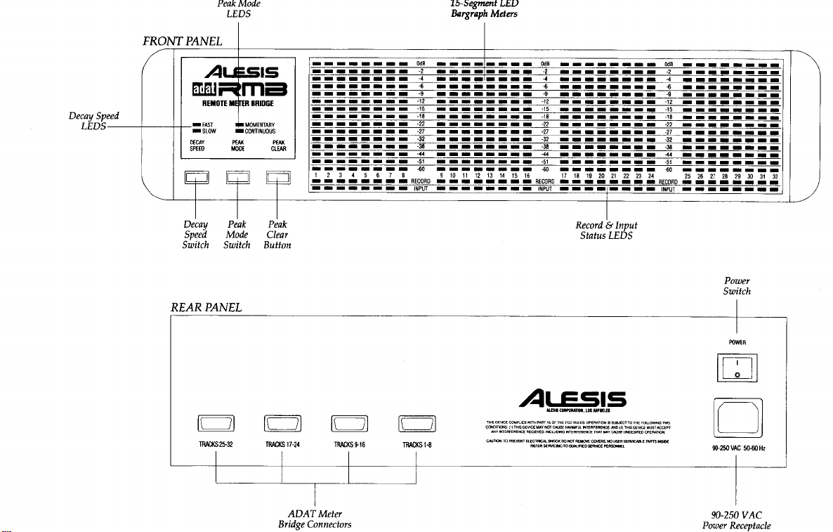
Front Panel
Indicators:
Rear
Connectors:
Power Requirements:
Dimensions(HxWxD):
Weight:
Shipping
Accessories Induded:
Optional
Controls
Panel
Controls and
Weight:
Accessories:
and
lc
SPECIIIGAITONS
32
drannels
32
bargraph
LED indicators for
input
status;
Decay
Speed, Peak Mode and
Peak Clea4 LED indicators for
Decay Speed
Peak Mode
Continuous).
Four 9 pin
ADAT; AC
AC
spec
90-250 VAC, 5(H0 FIz,50
max.
x79" x3-7/2"
3-l/2"
(2
Rack
(1.9
4lbs
(a.9
11
bs
IEC style AC power
Owne/s
30' snake of
connectors
BRC mounting
rack ears and
AI-1 Digital Interface and
Sample
Master
BRC
1S-segment
of
indicators;
Pushbuttons for
(Fast,
(Momentary,
D-Sub connectors for
power
cord connector.
Spaces)
kg)
kg)
Manual
four 9 pin
bracket,
two support
Rate
Converter
Remote
LED
pairs
32
record/
track
Slow) and
switch; IEC-
W
cord
D-
screws/
legs
Control
of
10
Page 15

4.1 APPENDIX
2:
TUATNITENANGE/SERYTGE
TNFOR.TUATION
4.1A
Cleaning
Disconnect
RMB's metal and plastic
abrasives
4.18 Maintenance
Here are some
o
Periodically
o
Unplug the
time.
4.1C
Servicing
NOT ATTEMPT REPAIRS
DO
USER SERVICEABLE
servicing to
OBTAIN
THE
the AC cord, then use a
that mav harm the
A RETURN AUTHORIZATION NUMBER BEFORE
IS
UNIT
damp cloth to dean the
surfaces. Do not use
surfaces.
for preventive maintenance:
tips
check the AC cord for signs of fraying or damage.
RMB
when not in use
PARTS INSIDE THE RMB. Refer all
Alesis. YOU MUST FIRST
REruRNED
TO
for
YOURSELF. THERE
ALESIS.
solvents or
extended
CONTACT
periods
ARE NO
ALESIS TO
harsh
of
11
Page 16

,NSIRUGI/,ONS
JO f']E
USEN,
This equipment has been
digital
provide reasonable protection
installation.
energy and, if not installed
cause harmful interference
guarantee
equipment does cause harmful interference
which
can be determined
encouraged
measures:
This
equipment has been
computing
with FCC
Operation
in interference
and modifications made
could void the user's authority
pursuant
device,
This equipment generates, uses
interference
that
to try to correct the interference
o
Reorient
.
Increase
and receiver.
o
Connect the
different from
connected.
.
Consult the dealer
technician for help.
device, pursuant to FCC Rules.
regulations, shielded
non-approved
with
to radio and TV reception.
to Part 15 of the FCC Rules. These
and
tested
and used inaccordance
to
will not
by turning the equipment
or relocate
the separation
verified to comply
to the
found
against harmful
radio
communications.
in a particular
occur
receiving
the
between the
equipment into an outlet
that to which
an
or
experienced radio/TV
must
cables
equipment
equipment without
to operate
or
this equipment.
to comply with the limits for a dass B
limits are designed
interference in a residential
and can radiate radio frequency
with the instructions,
However,
installation. If
radio
to
by one or more
the
In
be used
The user is
or television
and
off
antenna.
equipment
on a circuit
receiver
with the limits for a
order to
unshielded
is
maintain
with this equipment.
cables is likely
cautioned
approval
the
there
reception,
o& the user is
of the
class
compliance
that changes
of
may
is
no
this
following
B
result
to
manufacturer
to
Page 17

ALESIS
L'MIIED
u'.AN.R.ANJY
ALESIS
ondworkmonshipforoperiodof I yeorfromtheddteof
worronv
worronfy
r.eploce
outhorized service reoresenlolive.
ond
instructions concerninq
occomponied by o deicription of
or on outhorized ALESIS repoir focility
Proof
other
to
design of
oitempted
use
AND FITNESS
OF
worronty losts, so
DAIv1AGES RESULTING
INCLUDING, AMONG OTHER THINGS, DAMAGE
INCONVENIENCE OR ON
PERMITTED BY LAW DAMAGES FOR PERSONAL
exclusion or
exclusion
vory trom
worronty
CORPORATION
is enforceoble only by the oriqinol retoil
protected
To
be
wifiin
cord
During lhe
To
updote ony unil relurned for repoir. ALESIS
This worronV
thot
ANY IMPLIED WARMNTIES, INCLUDING IMPLIED WARRANTIES OF
THIS LIMITED WARRANTY. Some stotes do
IN NO EVENT WILL
This
fhis worronty
worronV
Free of chorgJ ony
worron!
obtoin
telephone number
purchose
of
poiitive proof
producl
the
does
repoir
by unouthorized
due to
ore
FOR A PARTICUIAR PURPOSE, ARE LIMITED IN DURATION
limitotion
moy not
worronty girbi
to
slote
only opplies
informqtion iri
("ALESIS"I
w'orronty,
this
by
l4 doys
period
product thot proves to
service, lhe
prinied
where
presenbd
musl
be
product is within the
thot the
ot ony
not
cover cloims br domoqe
in moteriol
defects
the
obove
ALESIS
FROM THE BREACH
LOSS
incidentol or consequentiol domoges, so
of
you.
to
opply
you ipecific legol rights, ond
stote.
oll othei counlries
worronls this
the-purchoser
purchose.
of
ALESIS sholl, ot its sole ond obsolute option, eilher
purchoser
below to obtoin o
lo return the unit
problem.
the
postoge prepoid,
in the form of o bill of sole, concelled check
iime without
limitotion moy nol
BE LIABLE
to
prior
personnel,
workmonship
or
FOR INCIDENTAL, CONSEOUENTIAL OR OTHER
OF USE OF
products
sold
product
fir
be
originol
purchoser.
must complete ond
be defective on
first
must
Return Aufhorizotion Number
for
service.
,All
outhorized
worronty period.
reserves the right to
notice.
due io obuse,
onJis limited
not
ollow
opply
ANY EXPRESS OR IMPLIED
OF
THE PRODUCT, AND,
INJURY.
ond used in
pleose
refor to
wrife ALESIS
coll or
All inquiries musl be
rehrrns must be senl
insured
ond
to foiiure!
product.
in the
limitotions on how long on
you.
to
TO PROPERry DAMAGE BASED ON
Some
you
moy olso
the
United Stotes of
your locol
free
of defects
retoil
return the
inspection
properly pockoged.
ALESIS reserves
chonge
neolect,
oriiing during
TO THE EXIENT
slotes do not ollow
the
obo"e
hove other rights
distributrcr.
in moteriol
purchose.This
enclosed
repoir
ALESIS or its
by
the
ot
oddress
ond
to
or some
or improve
olterotion or
MERCHANTABILIW
TO THE LENGTH
WARRANW.
limilofion or
Americo. For
or
ALESIS
the right
normol
implied
the
which
3630
Los Angeles, Colifornio
-(800)-5-ALESIS
I
Your worronty will be in effect
you
ond
ONLY
Alesisoorporation 3630HoldrcgeA\,enue
1993
O
Alesis Corporation Sp€cificalions Subject To Chanoe Without Notice
will receive
IF YOU SEND
For Customer Service
LosAngeles CA 90016
r#Hlo*"*
90016
worronty informotion
IN YOUR WARRANTY CARD
In Mexico coll: 95-(800)-5-ALESIS
-tcG|Er
E
Printed
In USA
A299
7.51n072
 Loading...