

Page 1

DIGITAL MIXING CONSOLE
Owner’s Manual
4
5
6
7
8
9
10
11
12
+10 –20
+10
GAIN
13
+10 –20
+10
GAIN
PAD
1
26dB
+10 –34
SCENE
MEMORY
–60–16
2
26dB
+10 –34
UTILITY
–60–16
3
26dB
+10 –34
MIDI
–60–16
26dB
+10 –34
MIDI
REMOTE
–60–16
26dB
+10 –34
–60–16
26dB
+10 –34
–60–16
26dB
+10 –34
–60–16
26dB
+10 –34
–60–16
+10 –20
+10
GAIN
+10 –20
+10
GAIN
+10 –20
+10
GAIN
14
+10 –20
+10
GAIN
15
+10 –20
+10
GAIN
+10 –20
+10
SCENE MEMORYSETUP
PHONES
PHONES
ST IN
+10 –20
+10
GAINGAIN GAIN GAIN GAIN GAIN GAIN GAIN GAIN
MONITOR
SOLO/ 2TR IN
UNDO/
REDO
OUT
LEVEL
100
SOLO
SOLO
LEVEL
100
16
GAIN
DIO
AUX 1
FADER EFFECT 1
METER
SOLO SETUPGROUP/PAIR
CHANNEL CONTROL
DYNAMICSDELAY/Ø PAN/ROUTING
LO-MIDEQ LOW
EQ LIBRARY
FADER MODE
AUX 2
AUX 3 AUX 4
MIXING LAYER
1–16
EQ FLAT
AUTOMIX
VIEW
HIGHHI-MID
EFFECT 2
FUNCTION
SEL CH
FADER
STATUS
SCENE MEMORY
USER DEFINE
L STEREO R
EFFECT RTNST IN13–169–12FADER 1–8
STORE
USER DEFINE
12
CLIP
–3
–6
–9
–12
–15
–18
–24
–30
–36
–42
–48
34
CURSOR
17–24/MASTER
12345678910111213141516
17 18 19 20 21 22 23 24 AUX1 AUX2 AUX3 AUX4 BUS1 BUS2 BUS3 BUS4
SEL
SEL
SEL
SEL
SELONSEL
ON
ON
ON
ON
6
0
5
10
20
40
60
00
6
6
0
5
10
20
40
60
00
6
0
0
5
5
10
10
20
20
40
40
60
60
00
00
ON
6
6
0
0
5
5
10
10
20
20
40
40
60
60
00
00
SEL
SEL
ON
ON
6
6
0
0
5
5
10
10
20
20
40
40
60
60
00
00
SEL
SEL
ON
6
0
5
10
20
40
60
00
SEL
ON
ON
6
6
0
0
5
5
10
10
20
20
40
40
60
60
00
00
SEL
SEL
ON
6
0
5
10
20
40
60
00
SEL
SEL
ON
ON
ON
6
6
0
0
5
5
10
10
20
20
40
40
60
60
00
00
6
6
0
0
5
5
10
10
20
20
40
40
60
60
00
00
RECALL
PARAMETER
ENTER
12
EFFECT
RETURN
SEL
ON
6
0
5
10
20
40
60
00
ST OUT
SEL
ON
6
0
5
10
20
40
60
00
ST IN
SEL
SEL
ON
ON
6
0
5
10
20
40
60
00
12345678910111213141516
17 18 19 20 21 22 23 24 AUX1 AUX2 AUX3 AUX4 BUS1 BUS2 BUS3 BUS4
ST IN
EFFECT
RETURN
ST OUT
E
Page 2

ADVARSEL!
Lithiumbatteri—Eksplosionsfare ved fejlagtig
håndtering. Udskiftning må kun ske med batteri
af samme fabrikat og type. Levér det brugte
batteri tilbage til leverandoren.
VARNING
Explosionsfara vid felaktigt batteribyte. Använd
samma batterityp eller en ekvivalent typ som
rekommenderas av apparattillverkaren.
Kassera använt batteri enligt fabrikantens
instruktion.
VAROITUS
Paristo voi räjähtää, jos se on virheellisesti
asennettu. Vaihda paristo ainoastaan
laitevalmistajan suosittelemaan tyyppiin. Hävitä
käytetty paristo valmistajan ohjeiden
mukaisesti.
FCC INFORMATION (U.S.A.)
1. IMPORTANT NOTICE: DO NOT MODIFY THIS UNIT!
This product, when installed as indicated in the instructions contained in this manual, meets FCC requirements. Modifications not expressly approved by Yamaha
may void your authority, granted by the FCC, to use the product.
2. IMPORTANT: When connecting this product to accessories and/or another product use only high quality shielded cables. Cable/s supplied with this product MUST
be used. Follow all installation instructions. Failure to follow instructions could void your FCC authorization to use this product in the USA.
3. NOTE: This product has been tested and found to comply with the requirements listed in FCC Regulations, Part 15 for Class “B” digital devices. Compliance with
these requirements provides a reasonable level of assurance that your use of this product in a residential environment will not result in harmful interference with
other electronic devices. This equipment generates/uses radio frequencies and, if not installed and used according to the instructions found in the users manual, may
cause interference harmful to the operation of other electronic devices. Compliance with FCC regulations does not guarantee that interference will not occur in all
installations. If this product is found to be the source of interference, which can be determined by turning the unit “OFF” and “ON”, please try to eliminate the
problem by using one of the following measures:
Relocate either this product or the device that is being affected by the interference.
Utilize power outlets that are on different branch (circuit breaker or fuse) circuits or install AC line filter/s.
In the case of radio or TV interference, relocate/reorient the antenna. If the antenna lead-in is 300 ohm ribbon lead, change the lead-in to coaxial type cable.
If these corrective measures do not produce satisfactory results, please contact the local retailer authorized to distribute this type of product. If you can not locate the
appropriate retailer, please contact Yamaha Corporation of America, Electronic Service Division, 6600 Orangethorpe Ave, Buena Park, CA 90620
* This applies only to products distributed by YAMAHA CORPORATION OF AMERICA.
IMPORTANT NOTICE FOR
THE UNITED KINGDOM
Connecting the Plug and Cord
WARNING: THIS APPARATUS MUST BE EARTHED
IMPORTANT: The wires in this mains lead are coloured in accordance with
the following code:
GREEN-AND-YELLOW : EARTH
BLUE : NEUTRAL
BROWN : LIVE
As the colours of the wires in the mains lead of this apparatus may not
correspond with the coloured markings identifying the terminals in your
plug, proceed as follows:
The wire which is coloured GREEN and YELLOW must be connected to
the terminal in the plug which is marked by the letter E or by the safety earth
symbol or coloured GREEN and YELLOW.
The wire which is coloured BLUE must be connected to the terminal which
is marked with the letter N or coloured BLACK.
The wire which is coloured BROWN must be connected to the terminal
which is marked with the letter L or coloured RED.
* This applies only to products distributed by YAMAHA KEMBLE
MUSIC (U.K.) LTD.
NEDERLAND
● Dit apparaat bevat een lithium batterij voor geheugen
back-up.
● Raadpleeg uw leverancier over de verwijdering van de
batterij op het moment dat u het apparaat ann het einde
van de levensduur afdankt of de volgende Yamaha Service
Afdeiing:
Yamaha Music Nederland Service Afdeiing
Kanaalweg 18-G, 3526 KL UTRECHT
Tel. 030-2828425
● Gooi de batterij niet weg, maar lever hem in als KCA.
THE NETHERLANDS
● This apparatus contains a lithium battery for memory
back-up.
● For the removal of the battery at the moment of the
disposal at the end of the service life please consult your
retailer or Yamaha Service Center as follows:
Yamaha Music Nederland Service Center
Address: Kanaalweg 18-G, 3526 KL
UTRECHT
Tel: 030-2828425
● Do not throw away the battery. Instead, hand it in as small
chemical waste.
Page 3

i
Important Information
Read the Following Before Operating the 03D
Warnings
• Do not locate the 03D in a place subject to excessive heat or in direct sunlight. This
could be a fire hazard.
• Do not place the 03D in a place subject to ex c essiv e humidity or dust. This c ould be
a fire and electrical shock hazard.
• Connect the 03D power co rd only t o an AC outlet of the type stated in this Owner’s
Manual or as marked on the 03D . Failure t o do so is a fire and electrical shock hazard.
• Do not plug several devices into the same A C outlet. This can ov erload the AC outlet,
and can be a fire and electrical shock hazard. It ma y also affect the performanc e of
some devices.
• Do not place heavy objects on the pow er co rd. A damaged power cord is a potential
fire and electrical shock hazard.
• If the power cord is damaged (i.e., cut or a bar e wire is exposed), ask y our dealer for
a replacement. Using the 03D in this condition is a fire and shock hazard.
• Hold the power cord plug when disconnecting from an AC outlet. Never pull the
cord. Damaging the po w er c ord in this way is a potential fire and electrical shock
hazard.
• Do not place small metal objects on top of the 03D. M etal objects inside the 03D are
a fire and electrical shock hazard.
• Do not block the 03D ventilation holes. The 03D has v entilation holes at the top and
rear to prevent the internal temperature fr om rising. Block ed v entilation holes ar e a
fire hazard.
• Do not try to modify the 03D. This could be a fire and electrical shock hazard.
• The 03D operating temperature is between 5˚C and 35˚C (41˚F and 95˚F).
Cautions
• Turn off all audio devices and speakers when connecting to the 03D. Refer to the
owner’s manual for eac h device. Use the correct cables and connect as specified.
• If you notice any abnormality—such as smoke, odor, or noise—turn off the 03D
immediately . Remove the power cord from the AC outlet. Confirm that the abnormality is no longer present. Consult your dealer for r epair . U sing the 03D in this condition is a fire and shock hazard.
• If a foreign object or water gets inside the 03D, turn it off immediately. Remove the
power cord fr om the A C outlet. Consult y our dealer for repair . U sing the 03D in this
condition is a fire and electrical shock hazard.
• If you plan not to use the 03D for a long period of time, remove the po wer cord fr om
the AC outlet. Leaving the 03D connected is a fire hazard.
• Do not use benzene, thinner, cleaning detergent, or a chemical cloth to clean the
03D. Use only a soft, dry cloth.
• The 03D is a heavy piece of equipment. Al ways grip the underneath, not the side
panels, when lifting.
03D—Owner’s Manual
Page 4

ii
Interference
03D uses high-frequency digital circuits that may cause interference on radios and televisions placed close to it. If interference does occur, relocate the affected equipment.
Copyright
© 1997 Yamaha Corporation. All rights reserved.
No part of the 03D software or this Owner’s Manual may be reproduced or distributed
in any form or by any means without the prior written authorization of Yamaha Corporation.
Trademarks
ADAT MultiChannel Optical Digital Interface is a trademark and AD AT and Alesis are
registered trademarks of Alesis Corporation.
Dolby , AC-3, and Pro-Logic are trademarks of Dolby Laboratories Licensing Corporation. Copyright 1992 Dolby Laboratories, Inc. All rights reserved.
Fostex and RD-8 are trademarks of Fostex Corporation.
Macintosh is a registered trademark of Apple Computer, Inc.
Pro Tools is a registered trademark of Digidesign or Avid Technology, Inc.
Tascam Digital Interface is a trademark and Tascam and TEAC are registered trade-
marks of TEAC Corporation.
Windows is a trademark of Microsoft Corporation.
All other trademarks are the property of their respective holders and are hereby
acknowledged.
Package Contents
The 03D package should contain the following items. M ake sure that y ou have them all.
• 03D Digital Mixing Console
• This Owner’s M anual
Contact your Yamaha dealer if anything is missing.
Keep this manual for future reference!
03D—Owner’s Manual
Page 5

Contents
Contents
1 Welcome to the 03D . . . . . . . . . . . . . . . . . . . . . . . . 1
Welcome to 03D . . . . . . . . . . . . . . . . . . . . . . . . . . . . . . . . . . . . . . . . . . . . 2
About this Owner’s Manual . . . . . . . . . . . . . . . . . . . . . . . . . . . . . . . . . . . 2
03D Installation . . . . . . . . . . . . . . . . . . . . . . . . . . . . . . . . . . . . . . . . . . . . . 2
03D Features . . . . . . . . . . . . . . . . . . . . . . . . . . . . . . . . . . . . . . . . . . . . . . . . 3
Key Feature Discussion . . . . . . . . . . . . . . . . . . . . . . . . . . . . . . . . . . . . . . . 4
2 Touring the 03D . . . . . . . . . . . . . . . . . . . . . . . . . . . 9
Top Panel . . . . . . . . . . . . . . . . . . . . . . . . . . . . . . . . . . . . . . . . . . . . . . . . . 10
Rear Panel . . . . . . . . . . . . . . . . . . . . . . . . . . . . . . . . . . . . . . . . . . . . . . . . . 16
Block Diagram . . . . . . . . . . . . . . . . . . . . . . . . . . . . . . . . . . . . . . . . . . . . . 21
3 Getting Around the User Interface . . . . . . . . . . . . 23
About the User Interface . . . . . . . . . . . . . . . . . . . . . . . . . . . . . . . . . . . . . 24
Display . . . . . . . . . . . . . . . . . . . . . . . . . . . . . . . . . . . . . . . . . . . . . . . . . . . 24
Display Elements . . . . . . . . . . . . . . . . . . . . . . . . . . . . . . . . . . . . . . . . . . . 28
Cursor Buttons . . . . . . . . . . . . . . . . . . . . . . . . . . . . . . . . . . . . . . . . . . . . . 29
PARAMETER Wheel . . . . . . . . . . . . . . . . . . . . . . . . . . . . . . . . . . . . . . . . 29
ENTER Button . . . . . . . . . . . . . . . . . . . . . . . . . . . . . . . . . . . . . . . . . . . . . 29
Mouse . . . . . . . . . . . . . . . . . . . . . . . . . . . . . . . . . . . . . . . . . . . . . . . . . . . . 30
Mixing Layer . . . . . . . . . . . . . . . . . . . . . . . . . . . . . . . . . . . . . . . . . . . . . . . 31
Title Edit Dialog Box . . . . . . . . . . . . . . . . . . . . . . . . . . . . . . . . . . . . . . . . 33
iii
4 Input Channels . . . . . . . . . . . . . . . . . . . . . . . . . . . 35
Input Channel Overview . . . . . . . . . . . . . . . . . . . . . . . . . . . . . . . . . . . . . 36
Phantom Power (input channels 1–8) . . . . . . . . . . . . . . . . . . . . . . . . . . 37
Pad (input channels 1–8) . . . . . . . . . . . . . . . . . . . . . . . . . . . . . . . . . . . . 37
Gain . . . . . . . . . . . . . . . . . . . . . . . . . . . . . . . . . . . . . . . . . . . . . . . . . . . . . . 37
Metering . . . . . . . . . . . . . . . . . . . . . . . . . . . . . . . . . . . . . . . . . . . . . . . . . . 37
Insert (input channels 1 & 2) . . . . . . . . . . . . . . . . . . . . . . . . . . . . . . . . . 37
Attenuator . . . . . . . . . . . . . . . . . . . . . . . . . . . . . . . . . . . . . . . . . . . . . . . . 38
Phase . . . . . . . . . . . . . . . . . . . . . . . . . . . . . . . . . . . . . . . . . . . . . . . . . . . . . 39
Channel Delay . . . . . . . . . . . . . . . . . . . . . . . . . . . . . . . . . . . . . . . . . . . . . 40
Applying EQ to the Input Channels EQ . . . . . . . . . . . . . . . . . . . . . . . . 42
Dynamics Processor . . . . . . . . . . . . . . . . . . . . . . . . . . . . . . . . . . . . . . . . . 42
Muting Input Channels (ON/OFF) . . . . . . . . . . . . . . . . . . . . . . . . . . . . 42
Setting Input Channel Levels . . . . . . . . . . . . . . . . . . . . . . . . . . . . . . . . . 42
Pan, Balance & Routing . . . . . . . . . . . . . . . . . . . . . . . . . . . . . . . . . . . . . . 42
Direct Outputs . . . . . . . . . . . . . . . . . . . . . . . . . . . . . . . . . . . . . . . . . . . . . 43
Aux Sends . . . . . . . . . . . . . . . . . . . . . . . . . . . . . . . . . . . . . . . . . . . . . . . . . 43
Monitoring Input Channels . . . . . . . . . . . . . . . . . . . . . . . . . . . . . . . . . . 43
Input Channel Stereo Pairs . . . . . . . . . . . . . . . . . . . . . . . . . . . . . . . . . . . 43
Input Channels Block Diagram . . . . . . . . . . . . . . . . . . . . . . . . . . . . . . . 44
5 EQ . . . . . . . . . . . . . . . . . . . . . . . . . . . . . . . . . . . . . . 45
About 03D EQ . . . . . . . . . . . . . . . . . . . . . . . . . . . . . . . . . . . . . . . . . . . . . 46
Adjusting the EQ . . . . . . . . . . . . . . . . . . . . . . . . . . . . . . . . . . . . . . . . . . . 47
03D—Owner’s Manual
Page 6

iv
Contents
Bypassing the EQ . . . . . . . . . . . . . . . . . . . . . . . . . . . . . . . . . . . . . . . . . . . 47
Resetting the EQ Gain Controls . . . . . . . . . . . . . . . . . . . . . . . . . . . . . . . 47
EQ Library . . . . . . . . . . . . . . . . . . . . . . . . . . . . . . . . . . . . . . . . . . . . . . . . 48
Storing EQ Programs . . . . . . . . . . . . . . . . . . . . . . . . . . . . . . . . . . . . . . . . 49
Recalling EQ Programs . . . . . . . . . . . . . . . . . . . . . . . . . . . . . . . . . . . . . . 50
Editing EQ Program Titles . . . . . . . . . . . . . . . . . . . . . . . . . . . . . . . . . . . 51
Preset EQ Programs . . . . . . . . . . . . . . . . . . . . . . . . . . . . . . . . . . . . . . . . . 52
6 Pan, Routing & Surround Pan . . . . . . . . . . . . . . . . 57
Selecting a Pan Mode . . . . . . . . . . . . . . . . . . . . . . . . . . . . . . . . . . . . . . . . 58
Stereo Pan, Balance & Routing . . . . . . . . . . . . . . . . . . . . . . . . . . . . . . . . 59
Stereo Pairs, Pan & Routing . . . . . . . . . . . . . . . . . . . . . . . . . . . . . . . . . . 61
Surround Pan . . . . . . . . . . . . . . . . . . . . . . . . . . . . . . . . . . . . . . . . . . . . . . 62
Using Surround Pan . . . . . . . . . . . . . . . . . . . . . . . . . . . . . . . . . . . . . . . . 65
7 Solo, Monitors & Meters . . . . . . . . . . . . . . . . . . . . 71
About Monitor & Solo . . . . . . . . . . . . . . . . . . . . . . . . . . . . . . . . . . . . . . . 72
Monitor Outputs . . . . . . . . . . . . . . . . . . . . . . . . . . . . . . . . . . . . . . . . . . . 73
Phones . . . . . . . . . . . . . . . . . . . . . . . . . . . . . . . . . . . . . . . . . . . . . . . . . . . . 73
Monitoring . . . . . . . . . . . . . . . . . . . . . . . . . . . . . . . . . . . . . . . . . . . . . . . . 74
Setting Up Solo . . . . . . . . . . . . . . . . . . . . . . . . . . . . . . . . . . . . . . . . . . . . . 75
Using Solo . . . . . . . . . . . . . . . . . . . . . . . . . . . . . . . . . . . . . . . . . . . . . . . . . 76
Solo Safe . . . . . . . . . . . . . . . . . . . . . . . . . . . . . . . . . . . . . . . . . . . . . . . . . . 77
Two-track Input . . . . . . . . . . . . . . . . . . . . . . . . . . . . . . . . . . . . . . . . . . . . 77
Solo Block Diagram . . . . . . . . . . . . . . . . . . . . . . . . . . . . . . . . . . . . . . . . . 78
Metering . . . . . . . . . . . . . . . . . . . . . . . . . . . . . . . . . . . . . . . . . . . . . . . . . . 79
Monitor Block Diagram . . . . . . . . . . . . . . . . . . . . . . . . . . . . . . . . . . . . . 82
8 Stereo Output . . . . . . . . . . . . . . . . . . . . . . . . . . . . . 83
About the Stereo Output . . . . . . . . . . . . . . . . . . . . . . . . . . . . . . . . . . . . . 84
Analog Stereo Outputs . . . . . . . . . . . . . . . . . . . . . . . . . . . . . . . . . . . . . . 84
DIGITAL STEREO OUT . . . . . . . . . . . . . . . . . . . . . . . . . . . . . . . . . . . . . 84
Stereo Output & the YGDAI Interface . . . . . . . . . . . . . . . . . . . . . . . . . . 84
Rec Out & the Stereo Output . . . . . . . . . . . . . . . . . . . . . . . . . . . . . . . . . 84
Solo & the Stereo Output . . . . . . . . . . . . . . . . . . . . . . . . . . . . . . . . . . . . 84
Monitoring the Stereo Output . . . . . . . . . . . . . . . . . . . . . . . . . . . . . . . . 84
Metering the Stereo Output . . . . . . . . . . . . . . . . . . . . . . . . . . . . . . . . . . 84
Routing Signals to the Stereo Output . . . . . . . . . . . . . . . . . . . . . . . . . . 84
Setting the Stereo Output Level . . . . . . . . . . . . . . . . . . . . . . . . . . . . . . . 85
Muting the Stereo Output . . . . . . . . . . . . . . . . . . . . . . . . . . . . . . . . . . . . 85
Balancing the Stereo Output . . . . . . . . . . . . . . . . . . . . . . . . . . . . . . . . . . 85
Applying EQ to the Stereo Output . . . . . . . . . . . . . . . . . . . . . . . . . . . . . 85
Stereo Output Dynamics Processor . . . . . . . . . . . . . . . . . . . . . . . . . . . . 85
Stereo Output Delay . . . . . . . . . . . . . . . . . . . . . . . . . . . . . . . . . . . . . . . . 86
Stereo Output Block Diagram . . . . . . . . . . . . . . . . . . . . . . . . . . . . . . . . 87
9 Aux Sends . . . . . . . . . . . . . . . . . . . . . . . . . . . . . . . . 89
About Aux Sends . . . . . . . . . . . . . . . . . . . . . . . . . . . . . . . . . . . . . . . . . . . 90
Analog Aux Send Outputs . . . . . . . . . . . . . . . . . . . . . . . . . . . . . . . . . . . . 90
Aux Sends & the YGDAI Interface . . . . . . . . . . . . . . . . . . . . . . . . . . . . . 90
Monitoring Aux Sends . . . . . . . . . . . . . . . . . . . . . . . . . . . . . . . . . . . . . . 90
03D—Owner’s Manual
Page 7

Contents
Metering Aux Sends . . . . . . . . . . . . . . . . . . . . . . . . . . . . . . . . . . . . . . . . . 90
Sending Channel Signals to Aux Sends . . . . . . . . . . . . . . . . . . . . . . . . . 91
Pre-fader/Post-fader Aux Sends . . . . . . . . . . . . . . . . . . . . . . . . . . . . . . . 92
Setting Aux Send Master Levels . . . . . . . . . . . . . . . . . . . . . . . . . . . . . . . 93
Muting Aux Sends . . . . . . . . . . . . . . . . . . . . . . . . . . . . . . . . . . . . . . . . . . 93
Applying EQ to Aux Sends . . . . . . . . . . . . . . . . . . . . . . . . . . . . . . . . . . . 93
Aux Send Dynamics Processors . . . . . . . . . . . . . . . . . . . . . . . . . . . . . . . 93
Aux Send Stereo Pairs . . . . . . . . . . . . . . . . . . . . . . . . . . . . . . . . . . . . . . . 94
Aux Send Block Diagram . . . . . . . . . . . . . . . . . . . . . . . . . . . . . . . . . . . . 95
10 Bus Outs . . . . . . . . . . . . . . . . . . . . . . . . . . . . . . . . . 97
About Bus Outs . . . . . . . . . . . . . . . . . . . . . . . . . . . . . . . . . . . . . . . . . . . . 98
Analog Bus Outs . . . . . . . . . . . . . . . . . . . . . . . . . . . . . . . . . . . . . . . . . . . . 98
Bus Outs & the YGDAI Interface . . . . . . . . . . . . . . . . . . . . . . . . . . . . . . 98
Rec Out & Bus Outs 1 & 2 . . . . . . . . . . . . . . . . . . . . . . . . . . . . . . . . . . . . 98
Monitoring Bus Outs . . . . . . . . . . . . . . . . . . . . . . . . . . . . . . . . . . . . . . . . 98
Metering Bus Outs . . . . . . . . . . . . . . . . . . . . . . . . . . . . . . . . . . . . . . . . . . 98
Routing Signals to Bus Outs . . . . . . . . . . . . . . . . . . . . . . . . . . . . . . . . . . 98
Setting Bus Out Master Levels . . . . . . . . . . . . . . . . . . . . . . . . . . . . . . . . 99
Muting Bus Outs . . . . . . . . . . . . . . . . . . . . . . . . . . . . . . . . . . . . . . . . . . . 99
Applying EQ to Bus Outs . . . . . . . . . . . . . . . . . . . . . . . . . . . . . . . . . . . . 99
Bus Out Dynamics Processors . . . . . . . . . . . . . . . . . . . . . . . . . . . . . . . . 99
Bus Out Delay . . . . . . . . . . . . . . . . . . . . . . . . . . . . . . . . . . . . . . . . . . . . . 100
Routing Bus Signals to the Stereo Bus . . . . . . . . . . . . . . . . . . . . . . . . . . 101
Bus Out Stereo Pairs . . . . . . . . . . . . . . . . . . . . . . . . . . . . . . . . . . . . . . . . 101
Bus Out Block Diagram . . . . . . . . . . . . . . . . . . . . . . . . . . . . . . . . . . . . . . 102
v
11 Channel Library & View . . . . . . . . . . . . . . . . . . . . . 103
Channel Library . . . . . . . . . . . . . . . . . . . . . . . . . . . . . . . . . . . . . . . . . . . . 104
Storing Channel Programs . . . . . . . . . . . . . . . . . . . . . . . . . . . . . . . . . . . 105
Recalling Channel Programs . . . . . . . . . . . . . . . . . . . . . . . . . . . . . . . . . . 106
Editing Channel Program Titles . . . . . . . . . . . . . . . . . . . . . . . . . . . . . . . 107
Channel View . . . . . . . . . . . . . . . . . . . . . . . . . . . . . . . . . . . . . . . . . . . . . . 108
12 Groups & Pairs . . . . . . . . . . . . . . . . . . . . . . . . . . . . 111
Fader Groups . . . . . . . . . . . . . . . . . . . . . . . . . . . . . . . . . . . . . . . . . . . . . . 112
Mute Groups . . . . . . . . . . . . . . . . . . . . . . . . . . . . . . . . . . . . . . . . . . . . . . 113
Stereo Pairs . . . . . . . . . . . . . . . . . . . . . . . . . . . . . . . . . . . . . . . . . . . . . . . . 114
13 Onboard Effects . . . . . . . . . . . . . . . . . . . . . . . . . . . 117
About the Onboard Effects . . . . . . . . . . . . . . . . . . . . . . . . . . . . . . . . . . . 118
Preset Effects Programs . . . . . . . . . . . . . . . . . . . . . . . . . . . . . . . . . . . . . . 118
Applying Effects . . . . . . . . . . . . . . . . . . . . . . . . . . . . . . . . . . . . . . . . . . . . 122
Pre-fader/Post-fader Effects Sends . . . . . . . . . . . . . . . . . . . . . . . . . . . . . 123
Effects Returns . . . . . . . . . . . . . . . . . . . . . . . . . . . . . . . . . . . . . . . . . . . . . 123
Effects Library . . . . . . . . . . . . . . . . . . . . . . . . . . . . . . . . . . . . . . . . . . . . . . 125
Storing Effects Programs . . . . . . . . . . . . . . . . . . . . . . . . . . . . . . . . . . . . . 126
Recalling Effects Programs . . . . . . . . . . . . . . . . . . . . . . . . . . . . . . . . . . . 127
Editing Effects Program Titles . . . . . . . . . . . . . . . . . . . . . . . . . . . . . . . . 128
Effects Parameters . . . . . . . . . . . . . . . . . . . . . . . . . . . . . . . . . . . . . . . . . . 129
Effects Block Diagram . . . . . . . . . . . . . . . . . . . . . . . . . . . . . . . . . . . . . . . 142
03D—Owner’s Manual
Page 8

vi
Contents
14 Dynamics Processors . . . . . . . . . . . . . . . . . . . . . . 143
About the Dynamics Processors . . . . . . . . . . . . . . . . . . . . . . . . . . . . . . . 144
Patching in a Dynamics Processor . . . . . . . . . . . . . . . . . . . . . . . . . . . . . 146
Dynamics Library . . . . . . . . . . . . . . . . . . . . . . . . . . . . . . . . . . . . . . . . . . . 147
Storing a Dynamics Program . . . . . . . . . . . . . . . . . . . . . . . . . . . . . . . . . 148
Recalling a Dynamics Program . . . . . . . . . . . . . . . . . . . . . . . . . . . . . . . . 149
Editing Dynamics Program Titles . . . . . . . . . . . . . . . . . . . . . . . . . . . . . 150
Processor Types . . . . . . . . . . . . . . . . . . . . . . . . . . . . . . . . . . . . . . . . . . . . 151
Preset Dynamics Programs . . . . . . . . . . . . . . . . . . . . . . . . . . . . . . . . . . . 157
15 Scene Memories . . . . . . . . . . . . . . . . . . . . . . . . . . 163
About Scene Memories . . . . . . . . . . . . . . . . . . . . . . . . . . . . . . . . . . . . . . 164
What’s Stored in Scene Memories? . . . . . . . . . . . . . . . . . . . . . . . . . . . . 164
What’s the Edit Buffer & Edit Indicator? . . . . . . . . . . . . . . . . . . . . . . . . 164
Scene Memory 00 . . . . . . . . . . . . . . . . . . . . . . . . . . . . . . . . . . . . . . . . . . . 165
Scene Memory Display Area . . . . . . . . . . . . . . . . . . . . . . . . . . . . . . . . . . 165
Scene Memory Buttons . . . . . . . . . . . . . . . . . . . . . . . . . . . . . . . . . . . . . . 165
Storing Mix Scenes . . . . . . . . . . . . . . . . . . . . . . . . . . . . . . . . . . . . . . . . . . 166
Recalling Mix Scenes . . . . . . . . . . . . . . . . . . . . . . . . . . . . . . . . . . . . . . . . 168
Undoing Mix Scene Recalls . . . . . . . . . . . . . . . . . . . . . . . . . . . . . . . . . . . 169
Write Protecting Scene Memories . . . . . . . . . . . . . . . . . . . . . . . . . . . . . 170
Editing Scene Memory Titles . . . . . . . . . . . . . . . . . . . . . . . . . . . . . . . . . 171
Sorting Scene Memories . . . . . . . . . . . . . . . . . . . . . . . . . . . . . . . . . . . . . 172
Setting a Fade Time . . . . . . . . . . . . . . . . . . . . . . . . . . . . . . . . . . . . . . . . . 173
Recalling Scene Data Safely . . . . . . . . . . . . . . . . . . . . . . . . . . . . . . . . . . . 174
16 Automix . . . . . . . . . . . . . . . . . . . . . . . . . . . . . . . . 175
About Automix . . . . . . . . . . . . . . . . . . . . . . . . . . . . . . . . . . . . . . . . . . . . 176
Creating a New Automix . . . . . . . . . . . . . . . . . . . . . . . . . . . . . . . . . . . . . 180
Enabling Automix . . . . . . . . . . . . . . . . . . . . . . . . . . . . . . . . . . . . . . . . . . 180
Setting the Time Base . . . . . . . . . . . . . . . . . . . . . . . . . . . . . . . . . . . . . . . 181
Setting an Automix Offset . . . . . . . . . . . . . . . . . . . . . . . . . . . . . . . . . . . . 182
Safe Channels . . . . . . . . . . . . . . . . . . . . . . . . . . . . . . . . . . . . . . . . . . . . . . 183
Selecting Parameters for Recording . . . . . . . . . . . . . . . . . . . . . . . . . . . . 184
Recording an Automix . . . . . . . . . . . . . . . . . . . . . . . . . . . . . . . . . . . . . . 185
Playing Back an Automix . . . . . . . . . . . . . . . . . . . . . . . . . . . . . . . . . . . . 187
Rerecording Events . . . . . . . . . . . . . . . . . . . . . . . . . . . . . . . . . . . . . . . . . 188
Automix Punch-In/Punch-Out . . . . . . . . . . . . . . . . . . . . . . . . . . . . . . . 189
Editing Fader Moves On-the-fly . . . . . . . . . . . . . . . . . . . . . . . . . . . . . . . 190
Editing Events Off-line . . . . . . . . . . . . . . . . . . . . . . . . . . . . . . . . . . . . . . 193
Extracting Events . . . . . . . . . . . . . . . . . . . . . . . . . . . . . . . . . . . . . . . . . . . 198
Undoing Automix Operations . . . . . . . . . . . . . . . . . . . . . . . . . . . . . . . . 200
Clearing the Undo Buffer . . . . . . . . . . . . . . . . . . . . . . . . . . . . . . . . . . . . 201
Storing Automixes . . . . . . . . . . . . . . . . . . . . . . . . . . . . . . . . . . . . . . . . . . 202
Recalling Automixes . . . . . . . . . . . . . . . . . . . . . . . . . . . . . . . . . . . . . . . . 203
Swapping the Current Automix . . . . . . . . . . . . . . . . . . . . . . . . . . . . . . . 204
Editing Automix Titles . . . . . . . . . . . . . . . . . . . . . . . . . . . . . . . . . . . . . . 205
Clearing Automix Memories . . . . . . . . . . . . . . . . . . . . . . . . . . . . . . . . . 206
03D—Owner’s Manual
Page 9

Contents
17 Other Functions . . . . . . . . . . . . . . . . . . . . . . . . . . . 207
User Define Buttons . . . . . . . . . . . . . . . . . . . . . . . . . . . . . . . . . . . . . . . . 208
Using the Onboard Oscillator . . . . . . . . . . . . . . . . . . . . . . . . . . . . . . . . . 212
03D Preferences . . . . . . . . . . . . . . . . . . . . . . . . . . . . . . . . . . . . . . . . . . . . 213
Checking the Battery . . . . . . . . . . . . . . . . . . . . . . . . . . . . . . . . . . . . . . . . 214
Initializing the 03D . . . . . . . . . . . . . . . . . . . . . . . . . . . . . . . . . . . . . . . . . 214
Calibrating the Faders . . . . . . . . . . . . . . . . . . . . . . . . . . . . . . . . . . . . . . . 214
18 Digital I/O . . . . . . . . . . . . . . . . . . . . . . . . . . . . . . . 215
Wordclock Setup . . . . . . . . . . . . . . . . . . . . . . . . . . . . . . . . . . . . . . . . . . . 216
Digital Stereo Out . . . . . . . . . . . . . . . . . . . . . . . . . . . . . . . . . . . . . . . . . . 219
Output Dither . . . . . . . . . . . . . . . . . . . . . . . . . . . . . . . . . . . . . . . . . . . . . 220
Digital Stereo In . . . . . . . . . . . . . . . . . . . . . . . . . . . . . . . . . . . . . . . . . . . . 221
Digital Input Monitor . . . . . . . . . . . . . . . . . . . . . . . . . . . . . . . . . . . . . . . 222
YGDAI Cards . . . . . . . . . . . . . . . . . . . . . . . . . . . . . . . . . . . . . . . . . . . . . . 223
Cascading the 03D . . . . . . . . . . . . . . . . . . . . . . . . . . . . . . . . . . . . . . . . . . 227
19 MIDI . . . . . . . . . . . . . . . . . . . . . . . . . . . . . . . . . . . . 231
MIDI and the 03D . . . . . . . . . . . . . . . . . . . . . . . . . . . . . . . . . . . . . . . . . . 232
MIDI Connectors & TO HOST . . . . . . . . . . . . . . . . . . . . . . . . . . . . . . . 232
MIDI & TO HOST Data Receive Indicators . . . . . . . . . . . . . . . . . . . . . 233
MIDI/HOST Setup . . . . . . . . . . . . . . . . . . . . . . . . . . . . . . . . . . . . . . . . . 233
MIDI Setup . . . . . . . . . . . . . . . . . . . . . . . . . . . . . . . . . . . . . . . . . . . . . . . . 235
MIDI Monitor . . . . . . . . . . . . . . . . . . . . . . . . . . . . . . . . . . . . . . . . . . . . . 238
Program Change Assign . . . . . . . . . . . . . . . . . . . . . . . . . . . . . . . . . . . . . 239
Control Change Assign . . . . . . . . . . . . . . . . . . . . . . . . . . . . . . . . . . . . . . 240
System Exclusive Parameter Control . . . . . . . . . . . . . . . . . . . . . . . . . . . 241
Bulk Dump . . . . . . . . . . . . . . . . . . . . . . . . . . . . . . . . . . . . . . . . . . . . . . . . 242
MIDI Remote . . . . . . . . . . . . . . . . . . . . . . . . . . . . . . . . . . . . . . . . . . . . . . 243
vii
Troubleshooting . . . . . . . . . . . . . . . . . . . . . . . . . . . . . 251
Appendix A: General . . . . . . . . . . . . . . . . . . . . . . . . . . 253
03D Level Diagram . . . . . . . . . . . . . . . . . . . . . . . . . . . . . . . . . . . . . . . . . 253
Display Messages . . . . . . . . . . . . . . . . . . . . . . . . . . . . . . . . . . . . . . . . . . . 254
Security Cover . . . . . . . . . . . . . . . . . . . . . . . . . . . . . . . . . . . . . . . . . . . . . 256
Rack-mounting Kit . . . . . . . . . . . . . . . . . . . . . . . . . . . . . . . . . . . . . . . . . 256
03D VEK (Video Edit Suite Software) . . . . . . . . . . . . . . . . . . . . . . . . . . 256
Appendix B: Specifications . . . . . . . . . . . . . . . . . . . . . 257
General Specs . . . . . . . . . . . . . . . . . . . . . . . . . . . . . . . . . . . . . . . . . . . . . . 257
Channel Specs . . . . . . . . . . . . . . . . . . . . . . . . . . . . . . . . . . . . . . . . . . . . . 259
Memory/Library Specs . . . . . . . . . . . . . . . . . . . . . . . . . . . . . . . . . . . . . . 262
EQ Specs . . . . . . . . . . . . . . . . . . . . . . . . . . . . . . . . . . . . . . . . . . . . . . . . . . 262
Analog Inputs Specs . . . . . . . . . . . . . . . . . . . . . . . . . . . . . . . . . . . . . . . . . 263
Analog Outputs Specs . . . . . . . . . . . . . . . . . . . . . . . . . . . . . . . . . . . . . . . 264
Digital Inputs Specs . . . . . . . . . . . . . . . . . . . . . . . . . . . . . . . . . . . . . . . . . 265
Digital Outputs Specs . . . . . . . . . . . . . . . . . . . . . . . . . . . . . . . . . . . . . . . 265
YGDAI Interface Card Specs . . . . . . . . . . . . . . . . . . . . . . . . . . . . . . . . . . 265
Control I/O Specs . . . . . . . . . . . . . . . . . . . . . . . . . . . . . . . . . . . . . . . . . . 265
03D Dimensions . . . . . . . . . . . . . . . . . . . . . . . . . . . . . . . . . . . . . . . . . . . . 266
03D—Owner’s Manual
Page 10

viii
Contents
Appendix C: MIDI . . . . . . . . . . . . . . . . . . . . . . . . . . . . 267
Scene Memory to Program Change Table . . . . . . . . . . . . . . . . . . . . . . . 267
Parameter to Control Change Table . . . . . . . . . . . . . . . . . . . . . . . . . . . 268
MIDI Data Format . . . . . . . . . . . . . . . . . . . . . . . . . . . . . . . . . . . . . . . . . . 271
Appendix D: Resources . . . . . . . . . . . . . . . . . . . . . . . 279
Books . . . . . . . . . . . . . . . . . . . . . . . . . . . . . . . . . . . . . . . . . . . . . . . . . . . . . 279
Yamaha Web Site . . . . . . . . . . . . . . . . . . . . . . . . . . . . . . . . . . . . . . . . . . . 279
Glossary . . . . . . . . . . . . . . . . . . . . . . . . . . . . . . . . . . . 281
Index . . . . . . . . . . . . . . . . . . . . . . . . . . . . . . . . . . . . . . 285
03D—Owner’s Manual
Page 11

Welcome to the 03D
Welcome to the 03D
1
1
In this chapter...
Welcome to 03D . . . . . . . . . . . . . . . . . . . . . . . . . . . . . . . . . . . . . . . . . . . . . . . . . . . 2
About this Owner’s Manual . . . . . . . . . . . . . . . . . . . . . . . . . . . . . . . . . . . . . . . . . . 2
03D Installation . . . . . . . . . . . . . . . . . . . . . . . . . . . . . . . . . . . . . . . . . . . . . . . . . . . 2
03D Features . . . . . . . . . . . . . . . . . . . . . . . . . . . . . . . . . . . . . . . . . . . . . . . . . . . . . . 3
Key Feature Discussion . . . . . . . . . . . . . . . . . . . . . . . . . . . . . . . . . . . . . . . . . . . . . 4
03D—Owner’s Manual
Page 12

2
Chapter 1—Welcome to the 03D
Welcome to 03D
Thank you for choosing the Yamaha 03D Digital Mixing Console. Based on the highly
successful 02R Digital Recording C onsole, the new Y amaha 03D has been designed with
music production and project studios in mind, although its unique and flexible features
will also appeal to audio post and sound reinforcement and installation providers.
About this Owner’s Manual
The 03D Owner’s Man ual c ontains all the information y ou need t o use your 03D Digital Mixing Console. U se the table of contents to find general information and familiarize yourself with the organization of this manual, and use the index to search for specific
items. A glossary of 03D-related jargon is provided on page 281.
Each chapter in this manual discusses a single area of the 03D. For example, “I nput
Channels” explains all about input channels, while “Sc ene Memories” explains all about
scene memories. The contents of most chapters are ob vious from the chapt er title.
Rather than repeat some explanations several times, it ems that ar e c ommon t o many
channels, such as EQ and the dynamics pr ocessors, are explained in their own chapte rs.
Where possible, the individual sections of a chapter have been organized in order of signal flow. The “Input Channel” chapter, for example, starts with the input connectors
and works through each input channel function, finishing up at the buses.
03D Installation
Site the 03D on a stable surface, somewher e that complies with the important information at the beginning of this manual. The 03D can be rack-mounted using the optional
rack-mount kit.
03D—Owner’s Manual
Page 13

03D Features
03D Features
03D Sonic Specs
• Linear 20-bit 64-times oversampling A/D converters
• Linear 20-bit 8-times oversampling D/A converters (ST OUT, MONITOR OUT)
• 105 dB typical dynamic range (ST IN to ST OUT)
• 20 Hz–20 kHz (+1, –3 dB) frequency r esponse
• 32-bit internal digital audio processing
• 44-bit digital EQ processing
03D Features
• 26 inputs (including 8 digital inputs)
• 18 outputs (including 8 assignable digital outputs)
• Continuously variable gain controls
• Balanced XLR inputs with +48 V phantom po w er on input c hannels 1 t o 8
3
• 26 dB pad on input channels 1 to 8
• Balanced phone jack inputs on input channels 1 to 16
• Analog inserts on input channels 1 and 2
• AES/EBU and Coaxial-type digital inputs and outputs
• Eight assignable digital outputs via Yamaha’s standard YGDAI interface
• Y GDAI Cascade option for twin 03D or 03D and 02R operation
• Analog or digital stereo cascade for easy channel expansion
• Versatile solo modes for comprehensive monitoring
• Four fader groups for multiple channel co ntrol
• Four mute groups for multiple c hannel m uting
• Stereo-pair operation for input channels, aux sends, and bus outs
• Four-band parametric EQ on virtually every input and output (160 bands of EQ)
• Po w erful EQ library with 40 preset programs and 40 user programs
• Four aux sends with analog outputs
• Two onboard effects processors with 64 preset programs and 32 user programs
• Dynamics processor on virtually every input and output (36 in total)
• Po w erful d ynamics library with 40 preset programs and 40 user programs
• Po w erful c hannel library with 2 preset programs and 49 user programs
• 51 scene memories for snapshot-style automation
• Built-in Automix function for mix automation referenced to MIDI timecode
• Large 320 x 240 dot liquid-crystal display with fluorescent backlight
• Optional PC-compatible serial mouse for quick navigation and editing
• Four user definable buttons for quick access t o fr equently used commands
• MIDI remote contr ol of Programmable Mix er 01, 02R, 03D, ProR3, RE V500, etc.
• Built-in MIDI interface for quick and simple connection t o a personal c omput er
• 60 mm motorized faders
03D—Owner’s Manual
Page 14

4
Chapter 1—Welcome to the 03D
Key Feature Discussion
Configuration
The 03D provides a total of 26 inputs (including 8 digital inputs), stereo output (analog
or digital), 4 bus outs, 4 aux sends, 2 internal effects sends, and 8 assignable digital outputs via a single Y GDAI (Yamaha General Digital Audio Interface) slot. Each input
channel features four-band parametric EQ and a dynamics processor . Input channels 1
to 8 feature balanced XLR and phone jack connections, with individually switched
phantom power. Inputs 1 and 2 feature analog inserts. Input delays can be used for
microphone-placement compensation, while output delays can be used for dela y-compensation in multi-speaker systems. The number of inputs can be increased by digitally
cascading two 03Ds together, sharing Bus, Aux, Stereo, and Solo buses. YGDAI digital
inputs and outputs can be configured as bus outs, aux sends, input channel dir ect outs,
or stereo outs. So although the 03D is a four -bus mixer, assigning the four buses and
four aux sends, or the channel direct outs to the YGDAI slot’s eight outputs allows
eight-track simultaneous recording.
Benefits of a Digital Mixer
You’re probably already familiar with the many benefits offered by digital audio , but
what exactly are the benefits for digital audio mixing? Well, an audio mixer has the job
of combining audio signals from various sources, at differing levels and impedances,
usually into a stereo mix. And it m ust do this without introducing any new distortions
and noise. Analog mix ers do a pretty good job, but even with the best designs, nonlinear
effects caused by circuit components are una voidable.
In the digital realm, audio mixing consists of adding and multiplying binary numbers
that represent audio signals. The DSP (Digital Signal Proc essor) c hips used for these
calculations never get their sums wrong. So once past the initial A/D c onv ersion, audio
signals are immune from signal degradation. With the 03D, noise, distortion, and
crosstalk are virtually eliminated. You’ll hear a new clarity in your mixes.
Once in the digital domain, it makes sense to keep audio data digital, as multiple
AD/DA conversions can degrade signal quality. With the optional YGDAI interface
cards, the 03D can be connect ed dir ectly t o a modular digital multitrack rec or d er,
thereby keeping audio data in the digital domain for both recor ding and mixing. The
final stereo mix can be transferred to a two-track digital recorder using the 03D’s
AES/EBU or Coaxial digital output.
Onboard digital effects and dynamics processors mean that signals remain in the digital
domain, eliminating unnecessary AD/DA conversion. Signal processing is performed
by third-generation Yamaha DSPs, as used in the Yamaha ProR3 Digital Reverberator.
03D—Owner’s Manual
03D Sonic Performance
The 03D’ s linear 20-bit 64-times o versampling A/D con v erters pr o vide a typical
dynamic range of 105 dB. The 03D can generate the industry standard sampling rates
of 44.1 kHz and 48 kHz, or synchronize to an external wordclock source from 32 kHz
–6% to 48 kHz +6%. The stereo output and monit or output featur e 20-bit 8-times
oversampling D/A con verters, while the aux sends and bus outs feature 18-bit 8-times
oversampling D/A con verters. Oversampling techniques effectively increase the internal sampling rate, so side effects caused by steep lo w-pass filters, which ar e used to filter
out sampling frequency components during D/A conversion, are virtually eliminated.
Consequently, audio signal integrity is maintained from input through to output.
Page 15

Key Feature Discussion
Four-band Parametric EQ & Library
The 03D input channels, stereo input c hannel, stereo output, bus outs, aux sends, and
onboard effects returns all feature four-band fully parametric EQ, with variable gain,
frequency , Q, and b ypass. That’s 160 bands of EQ! High and low EQ bands can be used
as shelving, peaking, or HPF and LPF, respectively. See EQ on page 45 for more information.
EQ settings can be stored as programs in the EQ library, with all channel settings in a
channel library program, or with all mix settings in a mix scene. Real-time EQ adjusts
can be automated using the onboard Automix function. See Au t omix on page 175 for
more information.
The EQ library contains 40 preset programs and 40 user programs. User programs
allow you to stor e fr equently used EQ settings, and they can be titled for easy identification. The unique collection of preset EQ programs are designed for specific applications and instruments, and provide a good referenc e and starting point when making
EQ adjustments. See EQ Library on page 48 for more information.
Motorized Faders
The 03D features 60 mm motorized faders that move automatically when a mix sc ene
is recalled or an automix is played, pr o viding a clear visual indication of fader levels. A
fade time of up to 10 seconds can be set individually for each mix scene. Faders can be
grouped together in one of four fader groups for multiple fader control. See Fader
Groups on page 112 for more information. Faders of a pair of channels configured as a
stereo pair move simultaneously. See Stereo Pairs on page 114 for mor e information.
5
The ST OUT and ST IN faders always control the ster eo output and ster eo input channel levels, respectively . The EFFECT RETURN fader controls the return levels of the
two onboard effects processors. The operation of faders 1 to 16, however, depends on
the selected mixing layer. When the mixing lay er is set t o 1–16, the faders work with
input channels 1 to 16. When set to 17–24/MASTER, however, they work with input
channels 17 to 24, the aux sends, and the bus outputs. See M ixing Lay er on page 31 for
more information. As well as perform channel level adjustments, faders are used as aux
send and effects send level controls. F ader operation is set using the FADER MODE
buttons. See Fader M ode on page 13 for mor e information.
Onboard Effects Processors
The 03D features two onboard stereo m ulti-effects pr oc essors: Effect 1 and Effect 2.
These provide a wide range of quality effects, including rev erb , delay, c horus, flange,
amp simulator , and more. There ar e 34 different effects types available. The effects pr ocessors are fed by the Effect 1 and Effect 2 buses, and the processed signals are returned
through the effects return channels. Effects can be applied to input channels and the
stereo input channel.
Effects settings can be stored as programs in the effects library, which contains 64 preset
programs and 32 user programs. User pr ograms allow you to store your own effects
programs, and they can be titled for easy identification. See Effects Library on page 125
for more information. Effects settings are also stored in mix scenes.
Existing outboard gear can be patched into the 03D via the four aux sends.
03D—Owner’s Manual
Page 16

6
Chapter 1—Welcome to the 03D
Onboard Dynamics Processors
Dynamics processors, pr o viding compr ession, ducking, gating, and e xpansion, are
available on all input channels, the stereo input channel, the stereo output, bus outs,
aux sends, and the onboard effects returns. That’ s a t otal of 36 dynamics processors!
Dynamics processors can be self triggering (i.e., the signal being processed is used as the
trigger signal), or triggered by a signal from another channel.
Dynamics settings can be stored as programs in the dynamics library, with all channel
settings in a channel library program, or with all mix settings in a mix scene. The
dynamics library contains 40 preset programs and 40 user programs. User pr ograms
allow you to stor e your o wn dynamics programs, and they can be titled for easy identification. See Dynamics Library on page 147 for more information.
Existing signal processing gear can be patched into the 03D via the analog insert connections on input channels 1 and 2.
YGDAI & Digital I/O
The 03D features a single YGDAI slot, providing eight digital inputs and eight assignable digital outputs. The 03D accepts the same single-size YGDAI cards as the 02R Digital Recording Console. These cards provide a direct, digital connection to modular
digital multitrack recorders, such as the Alesis ADAT, Tascam DA88 or DA38, and
AES/EBU and Yamaha (Y2) format equipment. See Y GD AI Cards on page 223 for more
information.
In addition, AES/EB U and C oaxial digital stereo inputs and outputs allow direct connection to digital recorders and other digital devices. Digital stereo signals can be
routed to the Stereo bus for cascade operation or to the ster eo input channel for mixing
and processing. See Digital Stereo In on page 221 for more information.
Easy-to-Learn GUI Interface
03D operation is both logical and intuitive. The large 320 x 240 dot display with fluorescent backlight uses graphical icons to represent controls, and provides a clear indication of current settings and EQ curves. A PC-compatible serial mouse can be
connected for quick navigation and parameter editing. On/off-type parameters can be
set with a simple click, and rotary controls can be dragged. The CH View page sho ws all
settings of the selected channel at a glance. See Channel V iew on page 108 for more
information.
Surround Pan
As well as normal stereo pan, the 03D featur es three surround pan modes: 2+2, 3+1,
and 3+2+1. In conjunction with the stereo out and bus outs, surround pan controls
allow you to pan channel signals in a two-dimensional space. Surround pan controls
can be used to move sounds in a circular motion, ellipsis, semicircle, or straight line.
Sounds can be moved around the two-dimensional spac e in r eal time using a mouse.
Normal stereo pan and surround pan mov ements can be automated using the A utomix
function. See Surround Pan on page 62 for more information.
03D—Owner’s Manual
Page 17

Key Feature Discussion
Scene Memories
On many mixers, the only way to store mix settings is with marker pen and masking
tape. W ith the 03D, however , virtually every mix setting can be stored as a mix scene in
one of the 03D’s 50 scene memories. Mix sc enes can be recalled instantly with just one
button press, or MIDI P r ogram Change command. Mix scenes can also be recalled as
part of a dynamic automix, providing “total automation ”. If you work on several
projects at a time, you can st ore the current mix scene so when you return to that
project, you can start again right where you left off. Scene memories also make light
work of night-after-night sound checks. Simply press recall to r eturn to the pr evious
night’s mix settings. For theater work, scene memories allow accurate and repeatable
sound changes between scenes.
Automix
The 03D’ s A utomix function pr ovides dynamic mix automation refer enced to an ext ernal timecode source. The ext e rnal timecode can be either MTC (MIDI Timecode) or
MIDI Clock. A ut omix can be used to recor d and playback fader mov es, channel mutes,
EQ changes, pan, and more. In addition, mix scene, EQ, c hannel, effects, and dynamics
library recalls can be included in an automix, combining snapshot and dynamic automixing for “total automation ”. Events r ec or ded in an aut o mix can be edit ed off-line.
Fader moves can be edited “on the fly”, or off-line using the Trim function. The Undo
function can be used to revert to the previous automix after making changes that you
do not want to keep.
7
MIDI
In addition to standard MIDI connectors, the 03D features a T O HOST connector . This
allows the 03D to be connected dir ectly t o a personal c omput er without a MIDI interface. By c onnecting other MIDI gear t o the 03D’s standar d MIDI c o nnect ors, the 03D
can be used as MIDI interface for an entire MIDI system.
All mix parameters that can be stored in a mix scene can be controlled using MIDI S ystem Exclusive messages. MIDI Program Change messages can be used to recall mix
scenes. U p t o 114 03D parameters can be assigned to MIDI C ontr ol Change messages
for 03D control from a remote device. Scene memory , library, and automix data can be
dumped to and from other MIDI devices, such as a MIDI data filer for backup and
archive, a contr olling computer, or another 03D. See MIDI on page 231 for more infor mation.
MMC (MIDI Machine Control) commands can be assigned to the 03D ’s four USER
DEFINE buttons for remote machine control (st op, play, rewind, forward, and rec ord).
Using the MIDI R emot e function, other MIDI gear can be controlled using the 03D’s
faders, [ON] buttons, and PARAMETER wheel. The 03D comes with MIDI Remot e
pages for the following: Yamaha Programmable Mix e r 01, 02R, and 03D digital consoles; Yamaha ProR3 and RE V500 digital rev e rbs; GM and XG compatible tone generators; and Pro Tools. Custom pages can be configured for use with other MIDI gear.
03D—Owner’s Manual
Page 18

8
Chapter 1—Welcome to the 03D
03D—Owner’s Manual
Page 19

Touring the 03D
9
Touring the 03D
2
In this chapter...
Top Panel . . . . . . . . . . . . . . . . . . . . . . . . . . . . . . . . . . . . . . . . . . . . . . . . . . . . . . . . 10
Rear P anel . . . . . . . . . . . . . . . . . . . . . . . . . . . . . . . . . . . . . . . . . . . . . . . . . . . . . . . 16
Block Diagram . . . . . . . . . . . . . . . . . . . . . . . . . . . . . . . . . . . . . . . . . . . . . . . . . . . 21
03D—Owner’s Manual
Page 20

10 Chapter 2—Touring the 03D
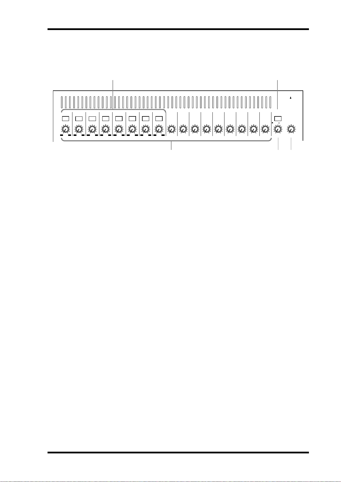
Top Panel
4
5
PAD
1
26dB
+10 –34
SCENE
MEMORY
–60–16
2
26dB
+10 –34
UTILITY
–60–16
3
26dB
+10 –34
MIDI
–60–16
26dB
+10 –34
MIDI
REMOTE
–60–16
+10 –34
26dB
–60–16
6
26dB
+10 –34
–60–16
7
26dB
+10 –34
–60–16
8
26dB
+10 –34
–60–16
9
+10 –20
+10
GAIN
10
+10 –20
+10
GAIN
11
+10 –20
+10
GAIN
12
+10 –20
+10
GAIN
13
+10 –20
+10
GAIN
14
+10 –20
+10
GAIN
15
+10 –20
+10
GAIN
+10 –20
+10
SCENE MEMORYSETUP
16
GAIN
ST IN
+10 –20
+10
GAINGAIN GAIN GAIN GAIN GAIN GAIN GAIN GAIN
MONITOR
SOLO/ 2TR IN
UNDO/
REDO
OUT
LEVEL
100
PHONES
PHONES
SOLO
SOLO
LEVEL
100
DIO
CHANNEL CONTROL
DYNAMICSDELAY/Ø PAN/ROUTING
LO-MIDEQ LOW
EQ LIBRARY
FADER MODE
AUX 1
AUX 2
FADER EFFECT 1
METER
MIXING LAYER
SOLO SETUPGROUP/PAIR
AUX 3 AUX 4
1–16
EQ FLAT
AUTOMIX
VIEW
HIGHHI-MID
EFFECT 2
FUNCTION
SEL CH
FADER
STATUS
SCENE MEMORY
USER DEFINE
EFFECT RTNST IN13–169–12FADER 1–8
L STEREO R
CLIP
–3
–6
–9
–12
–15
–18
–24
–30
–36
–42
–48
STORE
USER DEFINE
12
34
CURSOR
17–24/MASTER
12345678910111213141516
17 18 19 20 21 22 23 24 AUX1 AUX2 AUX3 AUX4 BUS1 BUS2 BUS3 BUS4
SEL
SEL
SEL
SEL
SELONSEL
ON
ON
ON
ON
6
0
5
10
20
40
60
00
6
6
0
5
10
20
40
60
00
6
0
0
5
5
10
10
20
20
40
40
60
60
00
00
ON
6
6
0
0
5
5
10
10
20
20
40
40
60
60
00
00
SEL
SEL
ON
ON
6
6
0
0
5
5
10
10
20
20
40
40
60
60
00
00
SEL
SEL
ON
6
0
5
10
20
40
60
00
SEL
ON
ON
6
6
0
0
5
5
10
10
20
20
40
40
60
60
00
00
SEL
SEL
ON
6
0
5
10
20
40
60
00
SEL
SEL
ON
ON
ON
6
6
0
0
5
5
10
10
20
20
40
40
60
60
00
00
6
6
0
0
5
5
10
10
20
20
40
40
60
60
00
00
RECALL
PARAMETER
ENTER
12
EFFECT
RETURN
SEL
ON
6
0
5
10
20
40
60
00
ST OUT
SEL
ON
6
0
5
10
20
40
60
00
ST IN
SEL
SEL
ON
ON
6
0
5
10
20
40
60
00
12345678910111213141516
17 18 19 20 21 22 23 24 AUX1 AUX2 AUX3 AUX4 BUS1 BUS2 BUS3 BUS4
The individual sections of the 03D control surface are explained on the following pages.
03D—Owner’s Manual
ST IN
EFFECT
RETURN
ST OUT
Page 21
PAD
1
26dB
+10 –34
–60–16
Analog Control Section
2
26dB
–60–16
+10 –34
A PAD switches
4
3
26dB
26dB
–60–16
+10 –34
+10 –34
These switches are used to turn on and off the input pads. See Pad (input channels 1–8)
on page 37 for more information.
Top Panel 11
1 3
ST IN
+10 –20
+10
GAINGAIN GAIN GAIN GAIN GAIN GAIN GAIN GAIN
MONITOR
SOLO/ 2TR IN
–60–16
5
26dB
+10 –34
–60–16
6
26dB
+10 –34
–60–16
7
26dB
+10 –34
–60–16
8
26dB
+10 –34
–60–16
9
+10 –20
+10
GAIN
10
+10 –20
+10
GAIN
11
+10 –20
+10
GAIN
12
+10 –20
+10
GAIN
13
+10 –20
+10
GAIN
14
+10 –20
+10
GAIN
15
+10 –20
+10
GAIN
16
+10 –20
+10
GAIN
PHONES
PHONES
OUT
100
LEVEL
LEVEL
42 5
100
B GAIN controls
These controls are used to adjust the gain of the input preamps. See Gain on page 37 for
more information.
C MONITOR OUT switch
This switch is used to select the signal source—SOLO or 2TR IN—for the MONITOR
OUT and PHONES.
D MONITOR OUT LEVEL control
This control sets the level of the signals appearing at the MONITOR OUT connectors.
The signal source is set using the adjacent MONITOR OUT switch.
E PHONES LEVEL control
This control is used to adjust the phones level. The signal source is set using the MONITOR OUT switch.
03D—Owner’s Manual
Page 22

12 Chapter 2—Touring the 03D
Display & Stereo Meters
FUNCTION
SEL CH
FADER
STATUS
SCENE MEMORY
1
USER DEFINE
EFFECT RTNST IN13–169–12FADER 1–8
L STEREO R
CLIP
–3
–6
–9
–12
–15
–18
–24
–30
–36
–42
–48
2
3
A Display
The large 320 x 240 dot display with fluorescent backlight provides clear indication of
mix settings and operating status. As well as sho wing parameter values numerically,
faders and rotary controls are represented graphically, so you can actually see pan and
fader positions. The display also sho ws EQ curves and signal level meters. See Display
on page 24 for more information.
B Stereo Output Meters
These 12-segment LED bar-type meters display the stereo output signal levels.
C Contrast
This control is used to adjust the display c ontrast. Adjust it so that the display is clear
and easy-to-read from your viewing position. You may need to readjust it when viewing
the display from a different height or angle.
Setup
SETUP
SCENE
MEMORY
UTILITY
MIDI
DIO
GROUP/PAIR SOLO SETUP
The Setup function buttons are used to access the follo wing setup and configuration
pages. The name of the selected function is shown on the display.
Button Pages
SCENE MEMORY
UTILITY
MIDI
DIO
GROUP/PAIR
SOLO SETUP
AUTOMIX
Scene Mem., Fade Time, RCL. Safe, Sort
Oscillator, Prefer., User Def., MIDI/HOST, MIDI Moni.
MIDI Setup, PGM Asgn., CTL Asgn., Bulk
D.in Setup, D.out Setup, Cascade, Monitor, Dither
Group, Pair
Solo Setup, Moni. Setup
Main, Memory, Fader Edit, Event Edit, Extract
AUTOMIX
03D—Owner’s Manual
Page 23

Channel Control
CHANNEL CONTROL
DYNAMICSDELAY/Ø PAN/ROUTING
Top Panel 13
VIEW
LO-MIDEQ LOW
EQ LIBRARY
HIGHHI-MID
EQ FLAT
The Channel function buttons are used to access the follo wing channel pages. The
name of the selected function is shown on the display.
Button Pages
DELAY/
DYNAMICS
∅
CH Delay, Dly 1–16, Dly 17–24, Output Dly, Phase
Dyn. Edit, Library
Pan 1-16, Pan 17–24, Surround, Bus to ST
PAN/ROUTING
(when a surround pan mode is selected, the Bus to ST page is
replaced by the Surr. 1–16 and Surr. 17–24 pages)
VIEW
EQ LOW, LO-MID,
HI-MID, HIGH
EQ LOW+LO-MID
CH View, Library
EQ
EQ Library
Fader Mode
FADER MODE
AUX 2
AUX 1
FADER EFFECT 1
METER
AUX 3 AUX 4
EFFECT 2
These buttons are used to select the following fader modes and display pages. The name
of the selected fader mode is shown on the display.
Button Fader Mode Pages
AUX 1
AUX 2
AUX 3
AUX 4
FADER (METER)
EFFECT 1
EFFECT 2
CH AUX 1 send AUX 1 Pre/Post, AUX Pan
CH AUX 2 send AUX 2 Pre/Post, AUX Pan
CH AUX 3 send AUX 3 Pre/Post, AUX Pan
CH AUX 4 send AUX 4 Pre/Post, AUX Pan
Normal CH fader CH 1–16, CH 17–24, YGDAI Out, Pre/Post
Effect 1 send Eff. Edit, Library, Pre/Post
Effect 2 send Eff. Edit, Library, Pre/Post
Fader functions are also affected by the Mixing La yer setting. See F aders on page 32 for
more information. When a Setup or Channel Contr ol butt on is pr essed, the Fader
mode automatically switches to Fader (i.e., normal fader mode).
Scene Memory
SCENE MEMORY
STORE
UNDO/
REDO
RECALL
These buttons are used to select, st ore, and recall scene memories, and undo and r edo
scene memory recalls. See Scene Me mories on page 163 for more information.
03D—Owner’s Manual
Page 24

14 Chapter 2—Touring the 03D
MIDI Remote
The [MIDI REMOTE] button activates the MIDI R emote mode. In this mode, the 03D
faders and [ON] buttons of channels 1 to 16 can be used to control other MIDI equipment using MIDI commands. The indicator in the butt on lights up when the MIDI
Remote mode is active. See MIDI Remote on page 243 for more information.
Solo
The [SOLO] button activates the SOL O mode. The indicat or in the button flashes when
the SOLO mode is active. See Setting Up Solo on page 75 for more information.
MIDI
REMOTE
SOLO
SOLO
User Define
USER DEFINE
1
2
3
4
The USER DEFINE buttons are user-programmable buttons that can be co nfigured to
send specific MIDI or MMC (MIDI Machine Control) commands when pr essed. They
can also be used to recall frequently used mix scenes or effects programs, adjust mix settings of the selected channel, or control the Automix function. These buttons are configured on the User Def. page. See User Define Buttons on page 208 for more
information.
Parameter Wheel, Cursors & Enter
PARAMETER
ENTER
CURSOR
03D—Owner’s Manual
These controls are used to na vigate ar ound the displa y pages and edit paramet ers. See
Getting Around the User Interface on page 23 for more information.
Page 25

1
2
3
Mixing Layer, SEL buttons, ON buttons, Faders
MIXING LAYER
1–16
17–24/MASTER
12345678910111213141516
17 18 19 20 21 22 23 24 AUX1 AUX2 AUX3 AUX4 BUS1 BUS2 BUS3 BUS4
SEL
SEL
SEL
SEL
SELONSEL
ON
ON
ON
ON
ON
SEL
SEL
ON
ON
SEL
SEL
ON
SEL
ON
ON
SEL
SEL
ON
SEL
ON
ON
SEL
SEL
ON
ON
Top Panel 15
12
EFFECT
RETURN
SEL
ON
ST OUT
SEL
ON
ST IN
SEL
ON
4
6
0
5
10
20
40
60
00
12345678910111213141516
17 18 19 20 21 22 23 24 AUX1 AUX2 AUX3 AUX4 BUS1 BUS2 BUS3 BUS4
6
6
0
0
5
5
10
10
20
20
40
40
60
60
00
00
6
6
0
5
10
20
40
60
00
6
0
0
5
5
10
10
20
20
40
40
60
60
00
00
6
6
0
0
5
5
10
10
20
20
40
40
60
60
00
00
6
6
0
0
5
5
10
10
20
20
40
40
60
60
00
00
6
6
0
0
5
5
10
10
20
20
40
40
60
60
00
00
6
6
0
0
5
5
10
10
20
20
40
40
60
60
00
00
6
6
0
0
5
5
10
10
20
20
40
40
60
60
00
00
A MIXING LAYER button
The [MIXING LAYER] button determines the functions of the faders, [ON] buttons,
and [SEL] buttons. When set to 1–16, these controls work with input channels 1 to 16.
When set to 17–24/MASTER, however , they work with input channels 17 to 24, the aux
sends, and the bus outputs. As well as the [MIXING LAYER] button, the function of the
faders is determined by the fader mode setting. The Mixing Lay e r setting is sho wn on
the display. See Display on page 24 for mor e information.
B SEL buttons
The [SEL] buttons are used to select channels for parameter editing. The name of the
selected channel is shown on the display . See Display on page 24 for mor e information.
The function of each [SEL] button depends on the selected Mixing Layer. See SEL Buttons on page 31 for more information. W ith aut omix, [SEL] butt ons ar e used to select
channels for recording. See A utomix on page 175 for more information. The [SEL] buttons are also used to select channels for the fader and mute gr oups. See G roups & P airs
on page 111 for more information.
6
0
5
10
20
40
60
00
ST IN
6
0
5
10
20
40
60
00
EFFECT
RETURN
6
0
5
10
20
40
60
00
ST OUT
C ON buttons
The [ON] buttons are used to turn input channels and outputs on and off. The function of each [ON] button depends on the selected Mixing Layer. See ON Buttons on
page 31 for more information. When the [SOLO] function is on, [ON] buttons work
as solo buttons, not mute butt ons.
D Faders
The faders are used to adjust input channel and output channel levels. The 03D features
60 mm motorized faders. The function of each fader depends on the selected fader
mode and Mixing Layer. See Faders on page 32 for more information. The selected
fader mode is shown on the display. See Display on page 24 for more information. I n
MIDI Remote mode, faders 1 to 16 can be used t o contr ol other MIDI equipment. See
MIDI Remote on page 243 for more information.
03D—Owner’s Manual
Page 26
16 Chapter 2—Touring the 03D
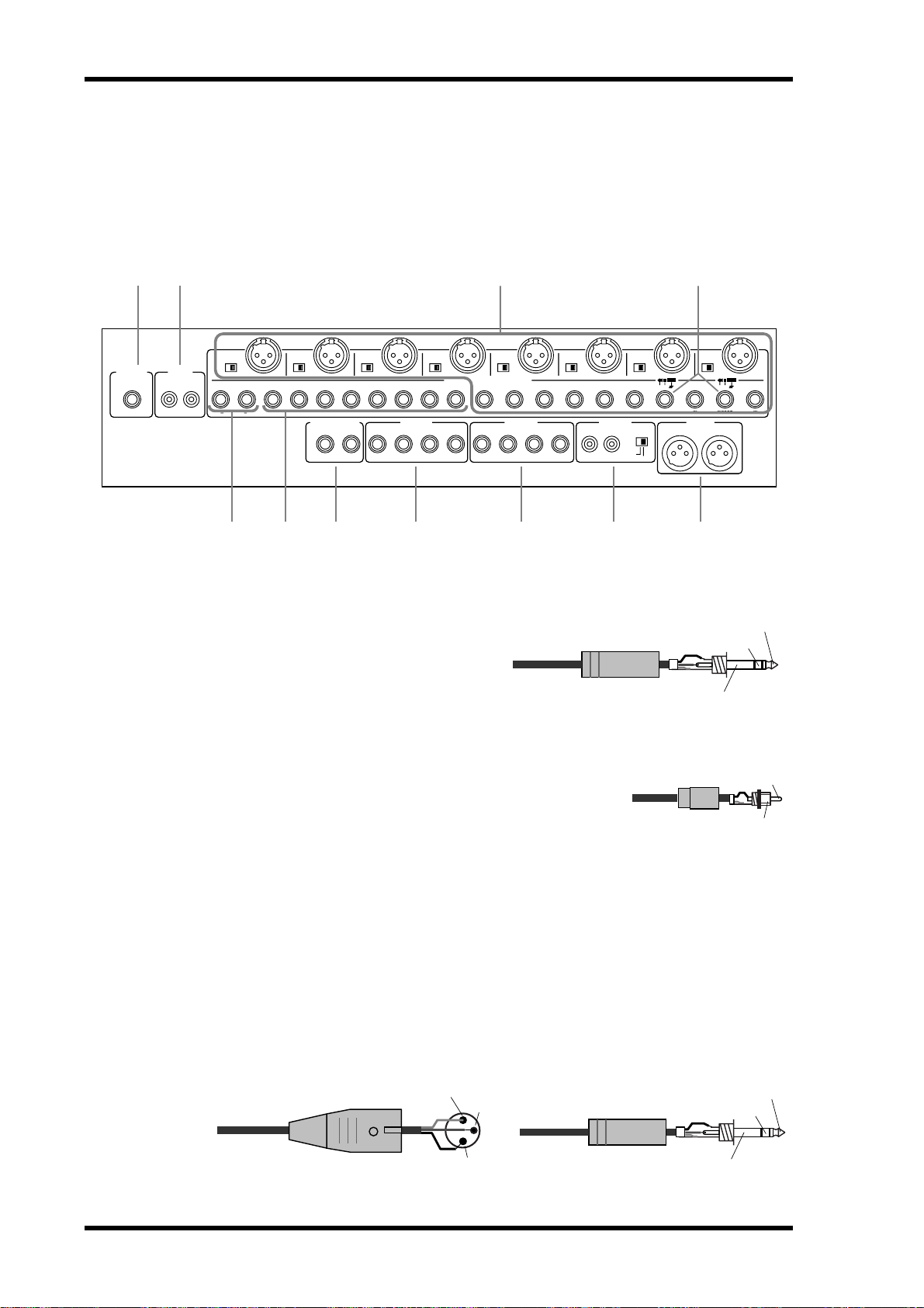
Rear Panel
Rear Panel—Top Half
The top half of the rear panel consists of analog inputs and outputs.
1 2 4
5
PHANTOM
ON OFF
(+48V)
BUS OUT
+4dB
2143
(BAL)
PHONES
2TR IN
R
–10dBV
(UNBAL)
8
PHANTOM
ON OFF
(+48V)
L
R
L
ST IN
7
PHANTOM
ON OFF
(+48V)
16 15 14 13
MONITOR OUT
RL
6
PHANTOM
ON OFF
(+48V)
12 11 10 8 7 6
+4dB
43
(BAL)
3
4
PHANTOM
ON OFF
INPUT(BAL) /CH1•2 INSERT (UNBAL)
(+48V)
AUX OUT
+4dB
(BAL)
PHANTOM
ON OFF
(+48V)
21
5
REC OUT
–10dBV
(UNBAL)
RL
23
PHANTOM
ON OFF
(+48V)
BUS OUT
1-L•2-R
39
SOURCE
SELECT
ST OUT
OUT IN
INSERT
2
4
75 6 8 9 J K
A PHONES
This is a stereo (TRS) phone jack. A pair
of stereo headphones can be connected
here for monitoring. The phones signal is
the same as the MONITOR OUT. The
phones level is set using the PHONES
LEVEL control.
1/4" TRS phone plug
1
PHANTOM
ON OFF
(+48V)
OUT IN
2
ST OUT
+4dB(BAL)
RL
1
3
INSERTININ
2
1
3
1
Tip (left)
Ring (right)
Sleeve (ground)
132231132231132231132231
B 2TR IN
These are phono jacks with a –10 dBV nominal input level.
Signals input here are fed through to the MONITOR OUT
SOLO/2TR IN switch and can be monitored via the MONITOR OUT and PHONES when that switch is set to 2TR IN.
The stereo outputs of a master recorder can be connect ed
here for confidence monitoring and master playback.
Phono plug
C INPUTs 1–8
Input channels 1 to 8 feature balanced XLR-3-31-type and balanced phone jack connectors, both with a nominal input range of –60 dB to +10 dB. Individually switchable
+48 V phantom powering is supplied to the XLR c onnect or. The phone jack has priority over the XLR-type connector, so when a phone plug is inserted, the XLR-type connector is disconnected. The phone jack inputs can also be used with unbalanced phone
plugs. With their high sensitivity and 26 dB P AD switc hes, these inputs can handle a
wide range of signals, from c ondenser microphones to “hot ” line levels.
Male XLR plug
1 (ground)
3 (cold)
2 (hot)
1/4" TRS phone plug
Ring (cold)
Sleeve (ground)
Tip
Sleeve
Tip (hot)
03D—Owner’s Manual
Page 27

Rear Panel 17
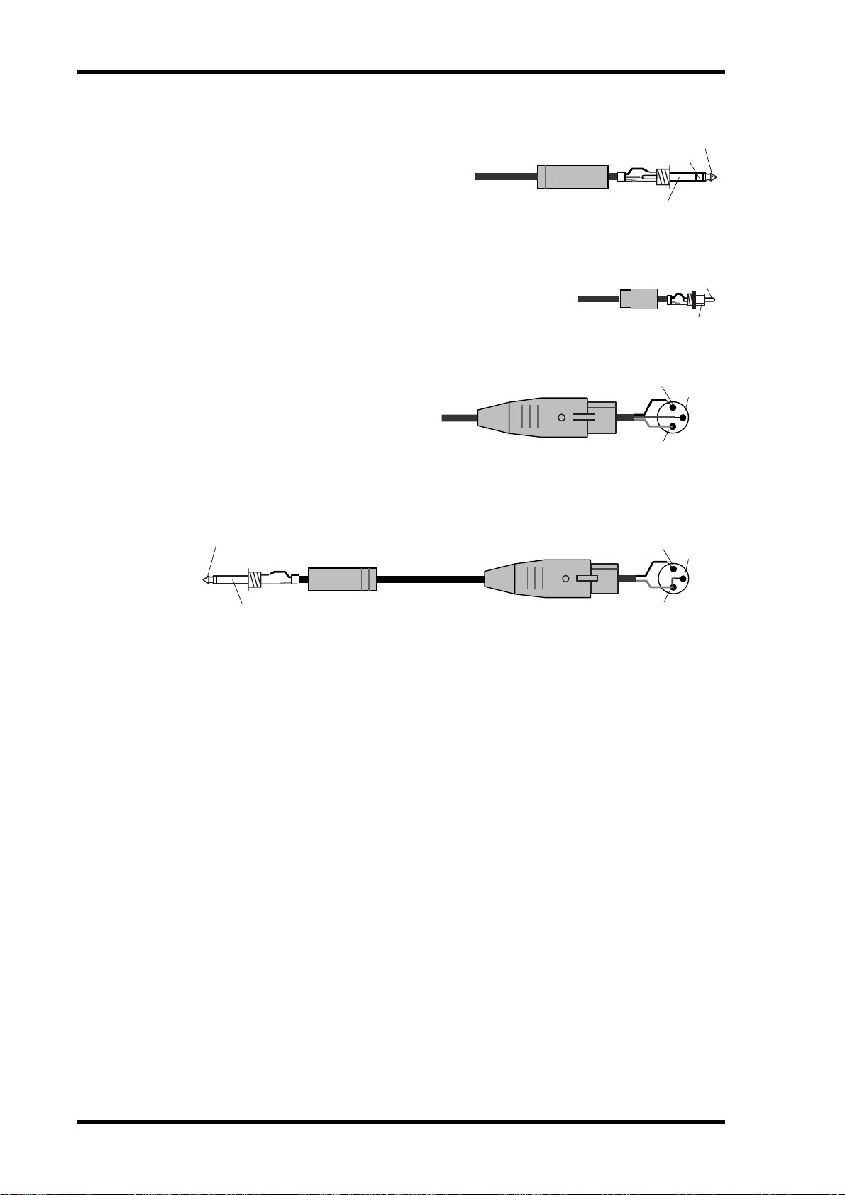
D INSERTs (input channels 1 and 2)
These TRS phone jack connectors are used to co nnect signal proc essors for use with
input channels 1 and 2 exclusively. Typically , compressors, limiters, and noise gates are
connected to this type of connection. They are wired: sleeve–ground, ring–return,
tip–send.
1/4" phone plug
Tip (send)
Tip (send)
Ring (return)
Sleeve (ground)
Connect to INSERT jack
1/4" TRS phone plug
E ST IN
These balanced phone jack inputs, with a
nominal input range of –20 dB to +10 dB,
are the inputs to the stereo input channel.
Either balanced or unbalanced phone plugs
can be connected. The st ereo outputs of an
external effects processor or other stereo
device can be connected here.
F INPUTs 9–16
Input channels 9–16 feature balanced
phone jack connectors with a nominal
input range of –20 to +10 dB. Either balanced or unbalanced phone plugs can be
connected. These inputs ar e best suited for
line-level signals.
To processor's input
1/4" phone plug
From processor's output
1/4" TRS phone plug
1/4" TRS phone plug
Sleeve (ground)
Tip (return)
Sleeve (ground)
Tip (hot)
Ring (cold)
Sleeve (ground)
Tip (hot)
Ring (cold)
Sleeve (ground)
G MONITOR OUT
These are balanced 1/4-inch phone jacks
with a +4 dB nominal output level. Either
1/4" TRS phone plug
balanced or unbalanced phone plugs can be
connected. They output the monitor signals and should be connected to the inputs
on a monitor amplifier . The monitor signal
source is determined by the MONIT OR
OUT SOLO/2TR IN switch. The output lev el is set using the MONITOR LEVEL control.
H BUS OUTs
These are balanced 1/4-inch phone jacks
with a +4 dB nominal output level. Either
balanced or unbalanced phone plugs can be
connected. They output the bus signals and
can be connected to multitrack recor ders,
power amplifiers, and so on.
1/4" TRS phone plug
Tip (hot)
Ring (cold)
Sleeve (ground)
Tip (hot)
Ring (cold)
Sleeve (ground)
03D—Owner’s Manual
Page 28
18 Chapter 2—Touring the 03D
I AUX OUTs
These are balanced 1/4-inch phone jacks
with a +4 dB nominal output level. Either
balanced or unbalanced phone plugs can be
connected. They output the aux send signals and can be used to feed external effects
processors, foldback amplifiers, and so on.
J REC OUT
These are phono jacks with a –10 dBV nominal output level.
The adjacent SOURCE SELECT switch is used to select the
signal source: ST OUT or BUS 1 and BUS 2. They can be
connected to a cassette, DAT, or other recorder.
K ST OUT
These are balanced XLR -3-32-type
connectors with a +4 dB nominal
output level. They are wired pin
1–ground, pin 2–hot (+), and pin
3–cold (–). They output the main stereo mix.
1/4" TRS phone plug
Phono plug
Female XLR plug
Tip (hot)
Ring (cold)
Sleeve (ground)
Sleeve
2 (hot)
3 (cold)
1 (ground)
Tip
If you need to connect the balanced ST OUT to an unbalanced phone jack input, use a
cable with the following wiring scheme (i.e., XLR pins 3 and 1 linked).
Tip (hot)
Sleeve (ground)
1/4" phone plug
Female XLR plug
2 (hot)
1 (ground)
3 (cold)
03D—Owner’s Manual
Page 29

Rear Panel—Lower Half
The lower half of the rear panel consists of digital and control I/O.
Rear Panel 19
1 2
TO EDITOR
POWER
ON/ OFF
MOUSE MIDI
3 4 5 6
TO HOST WORD CLOCK DIGITAL STEREO OUT DIGITAL STEREO IN
THRU
OUT
OUT
YGDAI SLOT
8CH INPUTS(CH17-24)/8CH OUTPUTS
75Ω
ON OFF
IN
IN
3
12 231
COAXIAL
AES/EBUAES/EBU
7 8 9
A POWER switch
This switch is used to turn on and off the 03D. I t ’s recessed to prevent accidental operation.
B TO EDITOR
This 9-pin D-sub connector is used to connect the 03D t o video-edit controllers. With
the current version of the 03D system software, how ev er, this function is not yet available.
C TO HOST
This 8-pin mini DIN connector is used to connect the 03D t o a personal comput er for
use with MIDI software. It eliminates the need for a separate MIDI interfac e, and
together with the MIDI standard connections allows the 03D to be used as a MIDI
interface for other MIDI equipment.
D WORD CLOCK
These BNC connectors are used to input and output the system’s wordclock. The 75Ω
wordclock termination switch allows the 03D to be used with various wordclock wiring
schemes. See Wordclock Setup on page 216.
E DIGITAL STEREO OUT
These two connectors are digital stereo outputs. They output the same digital audio signal but in different formats. The XLR-3-32-type connector outputs AES/EBU format
digital audio (24 bit), while the CO AXIAL connector outputs Consumer format digital
audio (20 bit).
F DIGITAL STEREO IN
These two connectors are digital stereo inputs, and only one c onnection can be used at
a time. The XLR -3-31-type connector accepts AES/EBU format digital audio, while the
COAXIAL c onnector accepts Consumer format digital audio . Signals input here can be
fed to the stereo input channel or directly to the St ereo bus for stereo cascade operation.
G MOUSE
An optional PC-compatible serial mouse can be connected here for quick na vigation
and parameter editing.
03D—Owner’s Manual
Page 30

20 Chapter 2—Touring the 03D
H MIDI IN, OUT, THRU
These are standard MIDI IN, OUT, and THR U co nnections. They ar e used to c onnect
the 03D to other MIDI equipment for control and synchronization.
I YGDAI slot
An optional YGDAI card can be installed here, providing access to the 03D’s eight digital inputs and outputs. See YGDAI Cards on page 223.
03D—Owner’s Manual
Page 31

Block Diagram
Block Diagram 21
+48V
SOLO
ST
EFF
AUX
BUS
COAXIAL
L R
L R
1 2
1 2 3 4
1 2 3 4
Meter
Meter
MeterMeter
Meter
PHANTOM
DIGITAL
STEREO
DITHER
PAN
CH Fader
Dynamics
4Band
DELAY
DC CUTAD
HA
PAD
OUT
ON
PEQ
AES/EBU
AUX 1
ATT
MeterMeter
AUX 2
GAIN
26dB
L
DA
DELAY
Dynamics
PEQ
4Band
AUX 3
AUX 4
EFF 1
+48V
ST OUT
ON
BALANCE
STEREO
EFF 2
PHANTOM
OUT
AUX/EFF
R
DA
DELAYDynamics
PEQ
4Band
PRE/POST
Same as 1, 2
DC CUT
AD
HA
PAD
SOLO/
2TR IN
Meter
Same as EFF1
EFFECT 2
L
DA
MONI
OUT
MONITOR
LEVEL
DA
MONO
TRIM
SINE 100Hz
SINE 1kHz
SINE 10kHz
PINK NOISE
R
PHONES
LEVEL
R
L
2TR IN
LEVEL
ON
PAN: INDIVIDUAL/GANG/INVERTED GANG
*
WAVEFORM
BURST NOISE
to
YGDAI
EFFECT 1, 2
ON
PEQ
INTERNAL
from EFF1
Meter
Meter
Meter Meter
Meter
PAN
*
BALANCE
4Band
EFFECT 1
AUX OUT
DA
Dynamics
PEQ
4Band
Dynamics
PEQ
1-4
1-4
ON
INTERNAL
from EFF2
*
BALANCE
Dynamics
PEQ
4Band
DELAY/
DC CUT
AD
HA
EFFECT
BUS OUT
2
DA
to REC OUT R
Same as 1
FLIP
3
DA
Same as 1
4
DA
Same as 1
ST CASCADE IN
ON/OFF
De-
Emphasis
SELECT
Meter
MeterMeter
Fader
EFF RTN
to INTERNAL
Dynamics
4Band
Meter
REC OUT
R
L
SOURCE
GAIN
26dB
SELECT
Ch9
from Ch1
Same as 1, 2
DC CUTAD
HA
from
BUS OUT 1, 2
DITHER
Ch2
GAIN
Ch10
Meter
1-8
CH OUTPUT
(YGDAI)
OUTPUT
DIRECT OUT
Same as 1, 2
ATT
De-
Emphasis
DITHER
Ch8
Ch7
Ch16
Ch15
INPUT
(YGDAI)
17-24
CH INPUT
to REC OUT L
Meter
from AUX OUT
MeterMeter
Meter
Meter
Meter
ST IN
Meter
Meter Meter
Meter
Fader
1
DA
DELAYDynamics
PEQ
4Band
Dynamics
PEQ
4Band
DELAY/
EFFECT
HA AD DC CUT
PAN
1
ON
PAN
ON
ATT
GAIN
This section is available only when
an optional YGDAI card is inserted.
L
ST IN
R
COAXIAL
DIGITAL
IN
STEREO
AES/EBU
IN
1, 2
1, 2
INSERT
3-8
3-8
INPUT
9-16
03D—Owner’s Manual
Page 32

22 Chapter 2—Touring the 03D
03D—Owner’s Manual
Page 33

Getting Around the User Interface 23
Getting Around the User Interface
3
In this chapter...
About the User I nt e rfac e . . . . . . . . . . . . . . . . . . . . . . . . . . . . . . . . . . . . . . . . . . . 24
Display . . . . . . . . . . . . . . . . . . . . . . . . . . . . . . . . . . . . . . . . . . . . . . . . . . . . . . . . . . 24
Display Elements . . . . . . . . . . . . . . . . . . . . . . . . . . . . . . . . . . . . . . . . . . . . . . . . . . 28
Cursor Buttons . . . . . . . . . . . . . . . . . . . . . . . . . . . . . . . . . . . . . . . . . . . . . . . . . . . 29
PARAMETER Wheel . . . . . . . . . . . . . . . . . . . . . . . . . . . . . . . . . . . . . . . . . . . . . . 29
ENTER Button . . . . . . . . . . . . . . . . . . . . . . . . . . . . . . . . . . . . . . . . . . . . . . . . . . . 29
Mouse . . . . . . . . . . . . . . . . . . . . . . . . . . . . . . . . . . . . . . . . . . . . . . . . . . . . . . . . . . . 30
Mixing Layer . . . . . . . . . . . . . . . . . . . . . . . . . . . . . . . . . . . . . . . . . . . . . . . . . . . . . 31
Title Edit Dialog Box . . . . . . . . . . . . . . . . . . . . . . . . . . . . . . . . . . . . . . . . . . . . . . 33
03D—Owner’s Manual
Page 34

24 Chapter 3—Getting Around the User Interface
About the User Interface
The 03D user interface is both straightforward and easy to use. A part from the GAIN
controls, [PAD] switches, scene memory buttons, and a few other buttons, there are
very few dedicated controls. The faders, [ON] buttons, and [SEL] buttons are multifunction controls whose operation depends on the Mixing Layer and fader mode settings. Mixing functions and configuration settings are organized int o display pages,
with up to five related pages being grouped together . For example, digital input and cascade pages are grouped together under DIO (digital I/O). P arameter selection and editing is carried out using the [CURSOR] buttons, [ENTER] button, and PARAMETER
wheel, which is detented for pr ecise and accurate editing. An optional mouse can be
connected for quick navigation around the display and parameter setting.
Display
The large 320 x 240 dot display with fluorescent backlight provides clear indication of
mix settings and operating status. As well as sho wing parameter values numerically,
faders and rotary controls are represented graphically, so you can actually see pan and
fader positions. The display also sho ws EQ curves and provides signal level meters.
The following illustration highlights the different areas of the display. These ar eas ar e
explained below .
Solo, Host, MIDI
Selected function
Selected channel
Scene memory
SCENE MEMORY
FUNCTION
SEL CH
User define
USER DEFINE
SIGNAL/PEAK
Menu button
Page area
FADER
Fader status
STATUS
EFFECT RTNST IN13–169–12FADER 1–8
Scene memory—This area of the display shows the selected scene memory number
and title, whether or not the scene memory is read-only or protected, and whether or
not the contents of the Edit Buffer have been edited. See Scene Memory Display Ar ea
on page 165 for more information.
Solo, Host, MIDI—Three indicators share this area of the display: SOLO appears
when the SOLO mode is active (U sing Solo on page 76). HOST appears when data is
received at the T O HOST connection. MIDI appears when data is rec eived at the MIDI
IN connection (MIDI & TO HOST Data Receive I ndicators on page 233).
03D—Owner’s Manual
User define—This area of the display shows the functions assigned to the USER
DEFINE buttons. See User Define Buttons on page 208 for more information.
Page 35

Display 25
Selected function—This area of the display shows the name of the function selected
using the Setup, Channel C ontr ol, and Fader mode buttons. The following functions
can be selected.
Setup Channel Control Fader Mode
SCENE MEMORY
UTILITY DYNAMICS AUX 2
MIDI PAN/ROUTING AUX 3
DIO VIEW AUX 4
GROUP/PAIR EQ LOW FADER (METER)
SOLO SETUP LO-MID EFFECT 1
AUTOMIX HI-MID EFFECT 2
MIDI REMOTE HIGH —
DELAY/
∅
AUX 1
Selected channel—This area of the display shows the selected channel. When chan-
nels are configured as a stereo pair, the number of each channel separated by a dash is
shown (e.g., 1–2 or 17–18). The follo wing channels can be selected.
CH 1 CH 2 CH 3 CH 4 CH 5 CH 6 CH 7 CH 8
CH 9 CH 10 CH 11 CH 12 CH 13 CH 14 CH 15 CH 16
CH 17 CH 18 CH 19 CH 20 CH 21 CH 22 CH 23 CH 24
AUX 1 AUX 2 AUX 3 AUX 4 BUS 1 BUS 2 BUS 3 BUS 4
ST IN EFFECT 1 EFFECT 2 ST OUT ————
When automix is operating, its status is displa y ed.
SIGNAL/PEAK—This area of the display always contains the SIGN AL and PEAK level
indicators. The SIGN AL indicat or lights up when the signal level is at –24 dB, and is
intended to show that a signal is present. The PEAK indicator lights up when the signal
is at –3 dB. These indicators are affected by the M ixing Lay er setting. W hen the Mixing
Layer is set to 1–16, the following channels are metered.
CH 1 CH 2 CH 3 CH 4 CH 5 CH 6 CH 7 CH 8
CH 9 CH 10 CH 11 CH 12 CH 13 CH 14 CH 15 CH 16
ST IN RTN 1 RTN 2 —————
When the Mixing Lay er is set t o 17–24/MASTER, the following channels are metered.
CH 17 CH 18 CH 19 CH 20 CH 21 CH 22 CH 23 CH 24
AUX 1 AUX 2 AUX 3 AUX 4 BUS 1 BUS 2 BUS 3 BUS 4
ST IN RTN 1 RTN 2 —————
Menu button—The Menu button is used in co njunction with a mouse to acc ess the
Menu Function. See Function Menu on page 30 for more information.
Page area—This area of the display is where the various setup, c onfiguration, and
mixing function pages appear. As well as showing parameter values numerically , faders
and rotary controls are represented graphically, so you can actually see pan and fader
03D—Owner’s Manual
Page 36

26 Chapter 3—Getting Around the User Interface
positions. See Display Elements on page 28 for more information. A n example page is
shown below .
The title of each page appears in a tab at the top of each page. The tab of the selected
page has a dark border , as shown below . P ages can be selected simply by clicking the tabs
with the mouse.
Selected page
Fader status—This area of the display shows the selected fader mode and Mixing
Layer. The top row indicates which channel the fader is co ntr olling (e.g., c hannel 1),
and the bottom row indicates which signal of that channel the fader is controlling (e.g.,
AUX 1 SEND). The following two tables show what is displa yed for the various fader
modes and Mixing Layer settings.
Mixing Layer 1–16
FADER
METER
AUX 1
AUX 2
EFFECT RTNST IN13–169–12FADER 1–8
EFFECT RTNST IN13–169–12FADER 1–8
EFFECT RTNST IN13–169–12FADER 1–8
03D—Owner’s Manual
AUX 3
EFFECT RTNST IN13–169–12FADER 1–8
AUX 4
EFFECT RTNST IN13–169–12FADER 1–8
Page 37
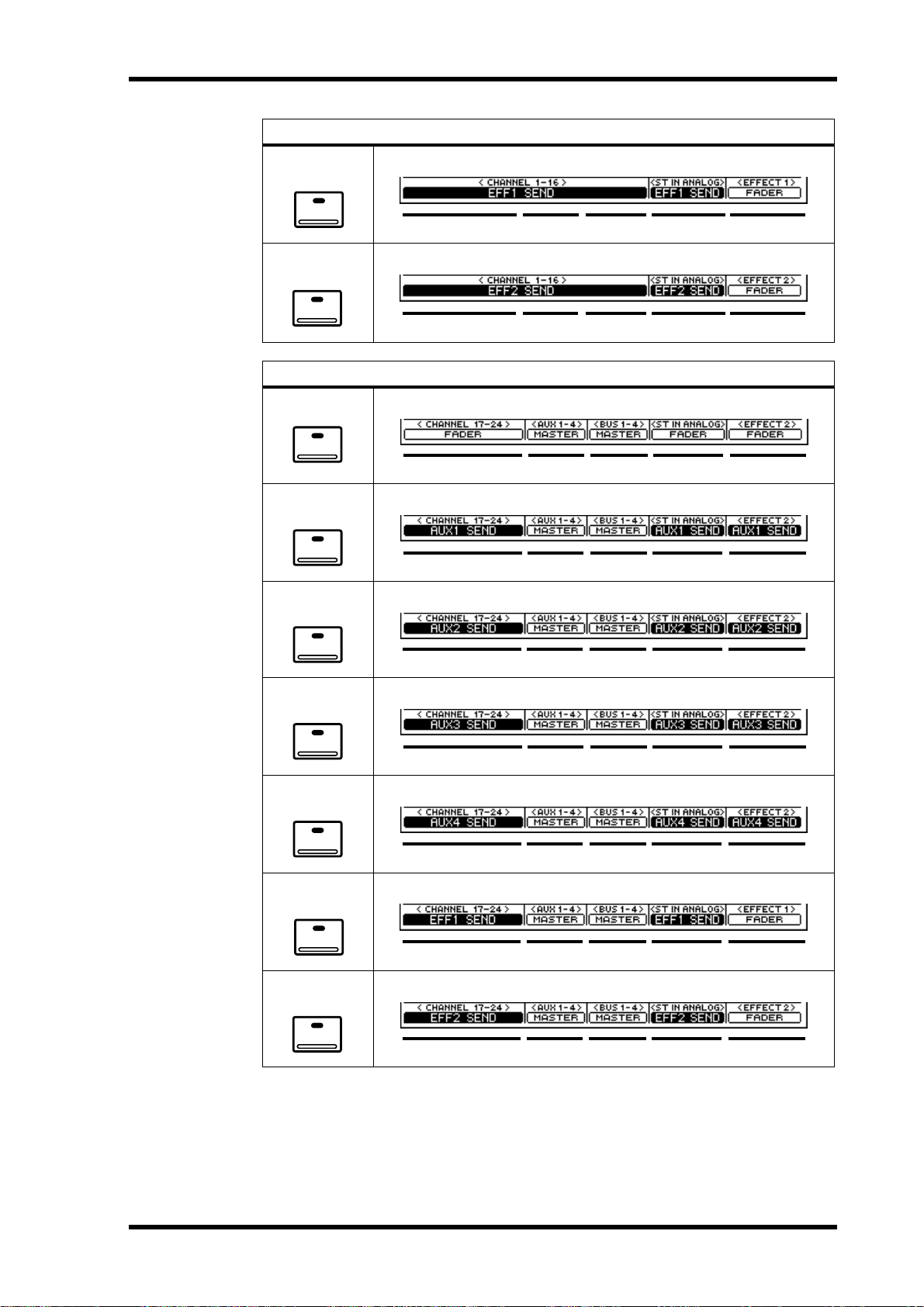
EFFECT 1
EFFECT 2
FADER
Display 27
Mixing Layer 1–16
EFFECT RTNST IN13–169–12FADER 1–8
EFFECT RTNST IN13–169–12FADER 1–8
Mixing Layer 17–24/MASTER
METER
AUX 1
AUX 2
AUX 3
AUX 4
EFFECT 1
EFFECT RTNST IN13–169–12FADER 1–8
EFFECT RTNST IN13–169–12FADER 1–8
EFFECT RTNST IN13–169–12FADER 1–8
EFFECT RTNST IN13–169–12FADER 1–8
EFFECT RTNST IN13–169–12FADER 1–8
EFFECT 2
EFFECT RTNST IN13–169–12FADER 1–8
EFFECT RTNST IN13–169–12FADER 1–8
03D—Owner’s Manual
Page 38

28 Chapter 3—Getting Around the User Interface
Display Elements
This section explains the various elements that appear on display pages.
Switches
Switches appear as box es with a shadowed outline (i.e., a thick er outline on the right side and bottom of the box).
Simple on/off-type switches are highlighted when they are turned
on. In this example, the [1] and [ST] switches are on.
The labels inside some switches change when they turned on or off,
as these Normal and Reverse phase switches show.
For option-type switches, only one option can be
chosen. In this example, the wordclock source is
set to INT 48K.
To operate a switch, use the cursor buttons to select it and the [ENTER] button to turn
it on or off. With a mouse, position the mouse cursor over the switch and click.
Rotary Controls
Parameters with a variable range appear as rotary controls, as this
example from the EQ page shows. To adjust a rotary control, use
the cursor buttons to select the control and the PARAMETER
wheel to adjust the value. To adjust a rotary control using a mouse,
position the mouse cursor over the control, press and hold the left
mouse button, and then drag the mouse. Parameters with a wide
range, such as effects delay times, can be adjusted m uch quicke r by
holding down the right mouse button and dragging. Rotary controls can also be adjusted in single-step increments by clicking once
with a mouse. Clicking with the left mouse button decreases a
value; clicking with the right button increases it.
Faders
Some pages, such as the CH View page, display faders graphically.
Usually, faders are adjusted using the real faders. Bu t they can also
be adjusted using the PARAMETER wheel or a mouse. To adjust a
fader using the PARAMETER wheel, use the cursor buttons to
select the fader and the PARAMETER wheel to adjust it. To adjust
a fader using a mouse, position the mouse cursor over the fader,
press and hold the left mouse button, and then drag the mouse.
Fader knobs appear highlighted when set to the nominal position.
Faders can also be adjusted in single-step increments by clicking
once with a mouse. Clicking with the left mouse button lowers the
fader; clicking with the right button raises it.
Nominal
03D—Owner’s Manual
Page 39
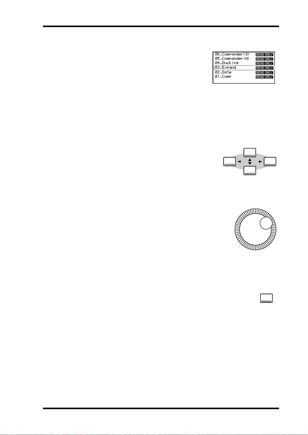
Parameter Boxes
CURSOR
Parameters that appear in parameter bo xes (i.e., dotted-line box es) can be set using the PARAMETER
wheel or a mouse. U se the cursor buttons to select the
parameter box and the P ARAMETER wheel to adjust.
If you are using a mouse, position the mouse cursor
over the parameter box, press and hold the left mouse
button, and then drag the mouse. Parameter boxes
can also be adjusted in single-step increments by
clicking once with a mouse. Clicking with the left
mouse button scrolls down one step; clicking with the
right button scrolls up one step.
Cursor Buttons
The cursor buttons are used to move the cursor ar ound
the display pages, selecting parameters and options. The
cursor appears as a flashing box, making it easy t o see
which parameter or option is currently selected. H olding
down a cursor button moves the cursor continuously in
the respective direction.
Cursor Buttons 29
PARAMETER Wheel
The PARAMETER wheel is used to adjust parameter values,
scroll through scene memory and library programs, and position the cursor when titling scene memories, effects programs,
and so on. Its detent ed action giv es it a positi ve feel, allowing
quick and accurate parameter editing. Turning it clockwise
increases parameter values; turning it counterclockwise
decreases them. Turning it fast allows rapid parameter editing.
ENTER Button
The [ENTER] button is used to activate parameter settings chosen using
the [CURSOR] buttons, and set on/off-type parameters, such as EQ
ON/OFF . It’ s also used to confirm settings and enter characters when titling
scene memories, effects programs, and so on. On some pages, such as the
EQ page, the [ENTER] button is used solely to turn the EQ on and off.
PARAMETER
ENTER
03D—Owner’s Manual
Page 40

30 Chapter 3—Getting Around the User Interface
Mouse
An optional mouse can be connected to the 03D for quick navigation
around the display and parameter setting. Simple on/off-type parameters can then be set with one click of the mouse, and rotary controls
can be dragged. The 03D should work with any PC-compatible serial
mouse (a mouse that supports both serial and PS-2 operation may not
work correctly with the 03D). The mouse should be co nnected to the
MOUSE connector on the 03D’s rear panel. The mouse speed can be
set to one of four speeds on the Prefer . page of the Utility function. See
MOUSE SPEED on page 213 for more information.
Most mouse operations can be performed using either the left or right
mouse button. Some parameters that have a wide range, such as
effects delay times, can be adjusted muc h quicker by holding down the
right mouse button and dragging. In this case, the left mouse button
works like a fine adjust control, while the right mouse button works as
a coarse adjust control. P arameters can also be adjusted in single-step
increments by clicking once with the mouse. Clicking with the left
mouse button decreases a value; clicking with the right button
increases it.
Display pages within the currently selected group can be selected simply by clicking on
page-title tabs, as shown below.
Page-title tabs
Function Menu
When a mouse is connected t o the 03D, the Function Menu sho wn below can be used
to access MIDI Remot e, Setup , Channel Control, and Fader M ode pages. The F unction
Menu is accessed b y clicking the M (Menu) button to the left of the page-title tabs, as
shown below. If the mouse is disconnected, the mouse cursor disappears aft er about
five minutes.
Click here to
access the
Function Menu
03D—Owner’s Manual
The Function menu disappears after 10 seconds if no switches are clicked.
Page 41
Mixing Layer 31
Mixing Layer
The 03D [SEL] buttons, [ON] buttons, and faders are multifunction controls. Their
exact operation depends on the selected Mixing Layer. Fader operation is also affected
by the Fader modes. The operation of all these controls is shown in the following tables.
As these tables show , the ST IN, EFFECT RETURN, and ST OUT [SEL] butt ons, [ON]
buttons, and faders are unaffected b y the M ixing Layer setting.
SEL Buttons
Mixing
Layer
1–16
17–24/
MASTER
1. During automix recording, the EFFECT RETURN [SEL] button is used to turn effect editing on and off. In this case, the [EFFECT 1] and [EFFECT 2] buttons should be used to
select Effect 1 and Effect 2.
1–8 9–12 13–16 ST IN EFF RTN ST OUT
CH 1–8
select
CH 17–24
select
CH 9–12
select
AUX 1–4
Master
select
SEL button
CH 13–16
select
BUS 1–4
Master
select
ST IN
select
1
EFF RTN
1/2 select
ST OUT
select
With automix, [SEL] buttons are used t o select channels for recording. See A utomix on
page 175 for more information. [SEL] buttons are also used to select channels for the
fader and mute groups. See Gr oups & Pairs on page 111 for more information.
ON Buttons
Mixing
Layer
1–16
17–24/
MASTER
1–8 9–12 13–16 ST IN EFF RTN ST OUT
CH 1–8
On/Off
CH 17–24
On/Off
CH 9–12
On/Off
AUX 1–4
Master
On/Off
ON button
CH 13–16
On/Off
BUS 1–4
Master
On/Off
ST IN
On/Off
EFF RTN 1/2
On/Off
ST OUT
On/Off
When the [SOLO] function is on, input channels 1 t o 24, the stereo input channel, and
effects returns channel’ s [ON] butt ons w ork as solo buttons, not mute buttons.
[ON] button operation is different in MIDI Remote mode. See MIDI R emot e on page
243 for more information.
03D—Owner’s Manual
Page 42

32 Chapter 3—Getting Around the User Interface
Faders
Mixing Layer: 1–16
Fader
Mode
Fader
(Meter)
Aux 1
Aux 2
Aux 3
Aux 4
Effect 1
Effect 2
1–8 9–12 13–16 ST IN EFF RTN ST OUT
CH 1–8
fader
CH 1–8
AUX 1 send
CH 1–8
AUX 2 send
CH 1–8
AUX 3 send
CH 1–8
AUX 4 send
CH 1–8
Eff 1 send
CH 1–8
Eff 2 send
CH 9–12
fader
CH 9–12
AUX 1 send
CH 9–12
AUX 2 send
CH 9–12
AUX 3 send
CH 9–12
AUX 4 send
CH 9–12
Eff 1 send
CH 9–12
Eff 2 send
Mixing Layer: 17–24/MASTER
Fader
Mode
Fader
(Meter)
Aux 1
Aux 2
Aux 3
Aux 4
Effect 1
Effect 2
1–8 9–12 13–16 ST IN EFF RTN ST OUT
CH 17–24
fader
CH 17–24
AUX 1 send
CH 17–24
AUX 2 send
CH 17–24
AUX 3 send
CH 17–24
AUX 4 send
CH 17–24
Eff 1 send
CH 17–24
Eff 2 send
Aux 1–4
Master fader
Fader
CH 13–16
fader
CH 13–16
AUX 1 send
CH 13–16
AUX 2 send
CH 13–16
AUX 3 send
CH 13–16
AUX 4 send
CH 13–16
Eff 1 send
CH 13–16
Eff 2 send
Fader
Bus 1–4
Master fader
ST IN
fader
ST IN
AUX 1 send
ST IN
AUX 2 send
ST IN
AUX 3 send
ST IN
AUX 4 send
ST IN
Eff 1 send
ST IN
Eff 2 send
EFF RTN 1/2
fader
EFF RTN 1/2
AUX 1 send
EFF RTN 1/2
AUX 2 send
EFF RTN 1/2
AUX 3 send
EFF RTN 1/2
AUX 4 send
EFF RTN 1
fader
EFF RTN 2
fader
Same as Mixing Layer 1–16
ST OUT
Master fader
03D—Owner’s Manual
Fader operation is different in MIDI Remote mode. See MIDI R emote on page 243 for
more information.
Page 43

Title Edit Dialog Box 33
Title Edit Dialog Box
The Title Edit dialog box is used to title mix sc enes, EQ pr ograms, dynamics pr ograms,
effects programs, channel programs, and aut omixes. It appears when storing or retitling a scene memory or program. Titles can be up to 12 characters long. A vailable char acters are shown on the following two screen shots. The SPC key is a space key.
SHIFT LOCK = ON
To position the cursor in the title, use the PARAMETER wheel or the
arrow switches on the Title Edit dialog bo x. If you are using a mouse,
simply click within the title.
T o enter a c haracter, use the cursor buttons to select a character , and then
press the [ENTER] button. If you are using a mouse, simply click a char acter . T o ac cess the lo w er case c haracters and various symbols, select the
SHIFT LOCK switch and press the [ENTER] button. Press SHIFT
LOCK again to access the upper case c haracters and n umbers.
Use the INS switch to insert a space at the cursor position and mov e subsequent characters to the right. Characters moved bey ond the right side
of the title window are lost.
Use the DEL switch to delete the c haracter at the cursor position and
move subsequent characters to the left.
When you’ve completed the title, select OK and press the [ENTER] button to continue, or select CANCEL and press the button [ENTER] to
cancel the operation.
03D—Owner’s Manual
Page 44

34 Chapter 3—Getting Around the User Interface
03D—Owner’s Manual
Page 45

Input Channels 35
Input Channels
4
In this chapter...
Input Channel Overview . . . . . . . . . . . . . . . . . . . . . . . . . . . . . . . . . . . . . . . . . . . 36
Phantom Power (input channels 1–8) . . . . . . . . . . . . . . . . . . . . . . . . . . . . . . . . 37
Pad (input channels 1–8) . . . . . . . . . . . . . . . . . . . . . . . . . . . . . . . . . . . . . . . . . . . 37
Gain . . . . . . . . . . . . . . . . . . . . . . . . . . . . . . . . . . . . . . . . . . . . . . . . . . . . . . . . . . . . 37
Metering . . . . . . . . . . . . . . . . . . . . . . . . . . . . . . . . . . . . . . . . . . . . . . . . . . . . . . . . . 37
Insert (input channels 1 & 2) . . . . . . . . . . . . . . . . . . . . . . . . . . . . . . . . . . . . . . . 37
Attenuator . . . . . . . . . . . . . . . . . . . . . . . . . . . . . . . . . . . . . . . . . . . . . . . . . . . . . . . 38
Phase . . . . . . . . . . . . . . . . . . . . . . . . . . . . . . . . . . . . . . . . . . . . . . . . . . . . . . . . . . . . 39
Channel Delay . . . . . . . . . . . . . . . . . . . . . . . . . . . . . . . . . . . . . . . . . . . . . . . . . . . . 40
Applying EQ to the Input Channels EQ . . . . . . . . . . . . . . . . . . . . . . . . . . . . . . 42
Dynamics Processor . . . . . . . . . . . . . . . . . . . . . . . . . . . . . . . . . . . . . . . . . . . . . . . 42
Muting Input Channels (ON/OFF) . . . . . . . . . . . . . . . . . . . . . . . . . . . . . . . . . . 42
Setting Input Channel Levels . . . . . . . . . . . . . . . . . . . . . . . . . . . . . . . . . . . . . . . . 42
Pan, Balance & Routing . . . . . . . . . . . . . . . . . . . . . . . . . . . . . . . . . . . . . . . . . . . . 42
Direct Outputs . . . . . . . . . . . . . . . . . . . . . . . . . . . . . . . . . . . . . . . . . . . . . . . . . . . 43
Aux Sends . . . . . . . . . . . . . . . . . . . . . . . . . . . . . . . . . . . . . . . . . . . . . . . . . . . . . . . 43
Monitoring Input Channels . . . . . . . . . . . . . . . . . . . . . . . . . . . . . . . . . . . . . . . . 43
Input Channel Stereo P airs . . . . . . . . . . . . . . . . . . . . . . . . . . . . . . . . . . . . . . . . . 43
Input Channels Block Diagram . . . . . . . . . . . . . . . . . . . . . . . . . . . . . . . . . . . . . 44
This chapter covers input c hannels 1 t o 24 and the st er eo input (ST IN). Unless otherwise stated, explanations refer to all of these inputs. The sections of this chapter are
arranged in order of signal flow, from input c onnect or through to bus.
03D—Owner’s Manual
Page 46

36 Chapter 4—Input Channels
Input Channel Overview
A full description of the rear panel connectors is provided on page 16.
Input Channels 1 & 2
XLR INPUT
1
2
3
Input Channels 3 to 8
2
3
(balanced)
Phone jack INPUT
(balanced)
Phantom Powering
INSERT
XLR INPUT
1
(balanced)
Input channels 1 and 2 feature balanced XLR -3-31-type and
balanced phone jack connectors, both with a nominal input
range of –60 dB to +10 dB. Individually switchable +48 V
phantom powering is supplied to the XLR connector. The
phone jack has priority over the XLR-type connector, so
when a phone plug is inserted, the XLR -type connector is
disconnected. The phone jack input can also be used with
unbalanced phone plugs. A TRS phone jack pr o vides a
post-gain, pre-A/D-conversion insert point.
Input channels 3 to 8 are identical to input channels 1 & 2
except they do not hav e inserts.
Phone jack INPUT
(balanced)
Phantom Powering
Input Channels 9 to 16
Phone jack INPUT
(balanced)
Input channels 9 to 16 are identical to input channels 1 t o 2
except they do not hav e inserts, XLR inputs, or phantom
powering.
Input Channels 17 to 24
Input channels 17 to 24 are identical to input channels 9 t o
16 except they do not hav e analog input c o nnect ors, a pad
YGDAI SLOT
switch, gain control, or dir ect out. These input c hannels are
accessed through the digital inputs of the YGDAI slot. See
YGDAI Cards on page 223 for more information.
Stereo Input Channel (ST IN)
Apart from being stereo and having a balance co ntrol,
231
Phone jack INPUTs
(balanced)
DIGITAL STEREO IN
COAXIAL
DIGITAL STEREO IN
AES/EBU
the stereo input channel has the same features as the
other input channels. One of three input sources can
be selected for the stereo input channel: analog phone
jacks, DIGITAL STEREO IN AES/EBU, or DIGITAL
STEREO IN COAXIAL. Input selection is made on
the D.in Setup page. See Digital Stereo I n on page 221
for more information.
03D—Owner’s Manual
Page 47

Phantom Power (input channels 1–8) 37
Phantom Power (input channels 1–8)
PHANTOM
ON OFF
(+48V)
Input channels 1 to 8 feature switchable +48 V phantom powering for use
with condenser-type microphones. Phantom pow ering is supplied to the
balanced XLR-3-31-type connector, and can be switched individually for
each channel. Phantom po w er should be turned on only when a c ondenser-type microphone is connected.
Pad (input channels 1–8)
Input channels 1 to 8 feature 26 dB pad switches. I nput pads att en uat e the
input signal by 26 dB, allowing the input preamp t o w ork with high-level
26dB
signals. You may need t o use a pad with “hot” signals from bass or snare
drum microphones, or “hot” line-level signals. PAD switch settings are not
stored in scene memories or channel programs, and cannot be c ontr olled
using automix.
Gain
GAIN controls adjust the gain of the input preamps. They are used to optimize the
input signal level for the best signal-to-noise performance, and should be set in conjunction with the level meters. Ideally, the GAIN control should be set so that the signal
level is relatively high, and it’ s okay for it to reach PEAK oc casionally . If PEAK is reached
often, how eve r, back off the GAIN control a little, otherwise, signal distortion may
occur . The GAIN control should be set with care. If it’s set too lo w, the signal-to-noise
performance will suffer. If it’s set too high, unpleasant signal clipping and distortion
may occur.
The GAIN controls on input channels 1 to 8 are designed for use with
microphone signals, and hav e an input sensiti vity of –16 dB to –60 dB.
Used in conjunction with the 26 dB PAD switches, however, these chan-
GAIN
–60–16
nels can also be used with line-level signals and “hot” microphone sig-
+10 –34
nals. With the pad switch on, the input sensiti vity is +10 to –34 dB.
The GAIN controls on input channels 9 to 16 and the stereo input (ST
IN) are designed for use with line-level signals, and have a gain range of
+10 –20
+10
GAIN
–10 dB to 20 dB.
GAIN control settings are not stored in sc ene memories or channel programs, and cannot be controlled using automix. GAIN c o ntr ols ar e, however, det ent ed for ac curate
repeat setting. The stereo input channel’s GAIN control is not detented.
Metering
Signal levels can be metered on the Meter pages. See Metering on page 79 for more
information.
Insert (input channels 1 & 2)
OUT IN
INSERT
Input channels 1 and 2 feature post-gain, pr e-A/D-con version insert points
via TRS phone jacks. These allow you to pat ch in your favorite external signal processors for exclusi ve use with input channels 1 and 2. Typically, compressors, limiters, and noise gates are connected to this type of connection.
The insert jacks are wired: sleeve–ground, ring–return, tip–send. A wiring
diagram for an insert cable is provided on page 17.
03D—Owner’s Manual
Page 48
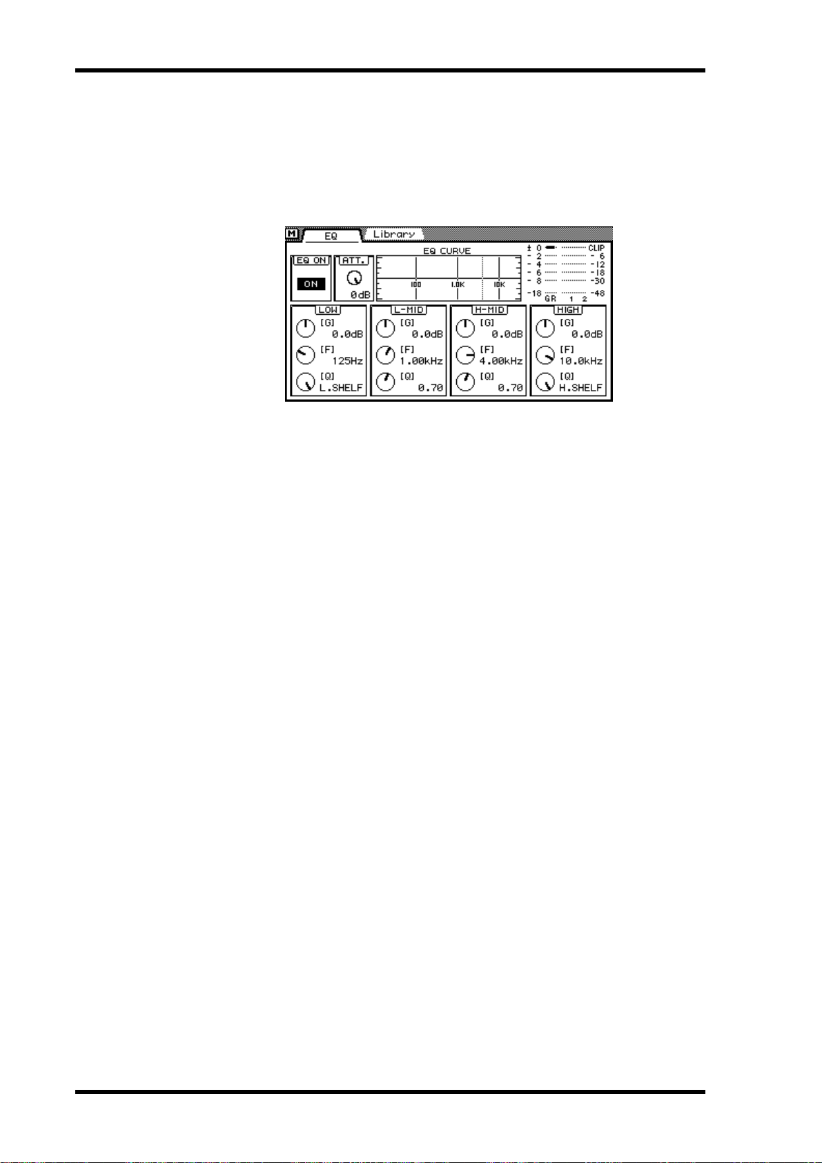
38 Chapter 4—Input Channels
Attenuator
After A/D conversion, input signals can be attenuated using the Attenuation function.
Signals can be attenuated from 0 dB to –96 dB in 1 dB steps. For digital inputs 17 to 24,
the Attenuation function comes after de-emphasis. Attenuation is set on the EQ page.
1. Press the [EQ LOW] button to locate the EQ page shown below.
2. Use the [SEL] and [MIXING LAYER] buttons to select a channel. See Mixing Layer on page 31 for more information.
3. Use the cursor button to select the ATT. control and the PARAMETER
wheel to adjust it.
If you are using a mouse, position the mouse cursor ov er the ATT. control, pr ess and
hold the left mouse button, and then drag the mouse.
The Atten uation function can be used t o c ompensat e for lev el incr eases caused b y EQ
boosting or dynamics processing. Inst ead of using a GAIN control to reduc e a boosted
signal, it’ s bett er to use the A ttenuation function. Although levels can be reduced using
the GAIN controls, this also r educ es the lev el of the signal being fed to the A/D converter , which is not desired. The Attenuation function c o mes after the A/D converter,
so A/D conversion performance is not affected.
When channels are co nfigur ed as a st er eo pair using the Pair function (Stereo Pairs on
page 114), the attenuators for each channel work t ogether , and parameter adjustments
can be made with either channel selected. You cannot set different parameters for the
odd and even channels.
03D—Owner’s Manual
Page 49

Phase 39
Phase
The Phase function reverses the phase of an input signal by 180 degrees. The phase can
be set for input channels 1 to 24 and the left and right channels of stereo input channel.
Phase reversal can be used to compensate for inc orr ectly wired balanced cables and
microphones. W hen a snar e drum is miked t op and bottom, the channel connected to
the bottom microphone can be phase reversed.
1. Use the [DELAY/∅] button to locate the Phase page shown below.
2. Use the [SEL] and [MIXING LAYER] buttons to select a channel. See Mixing Layer on page 31 for more information.
3. Use the [ENTER] button to set the phase of the selected channel.
Y ou can also use the cursor butt on to select the phase switches. If you are using a mouse,
simply click the phase switches. Phase switches can also be selected using the [SEL] buttons.
Normal phase
Phase reversed
The Phase function is not linked when channels are paired, and can be set independently for each channel in the stereo pair.
03D—Owner’s Manual
Page 50
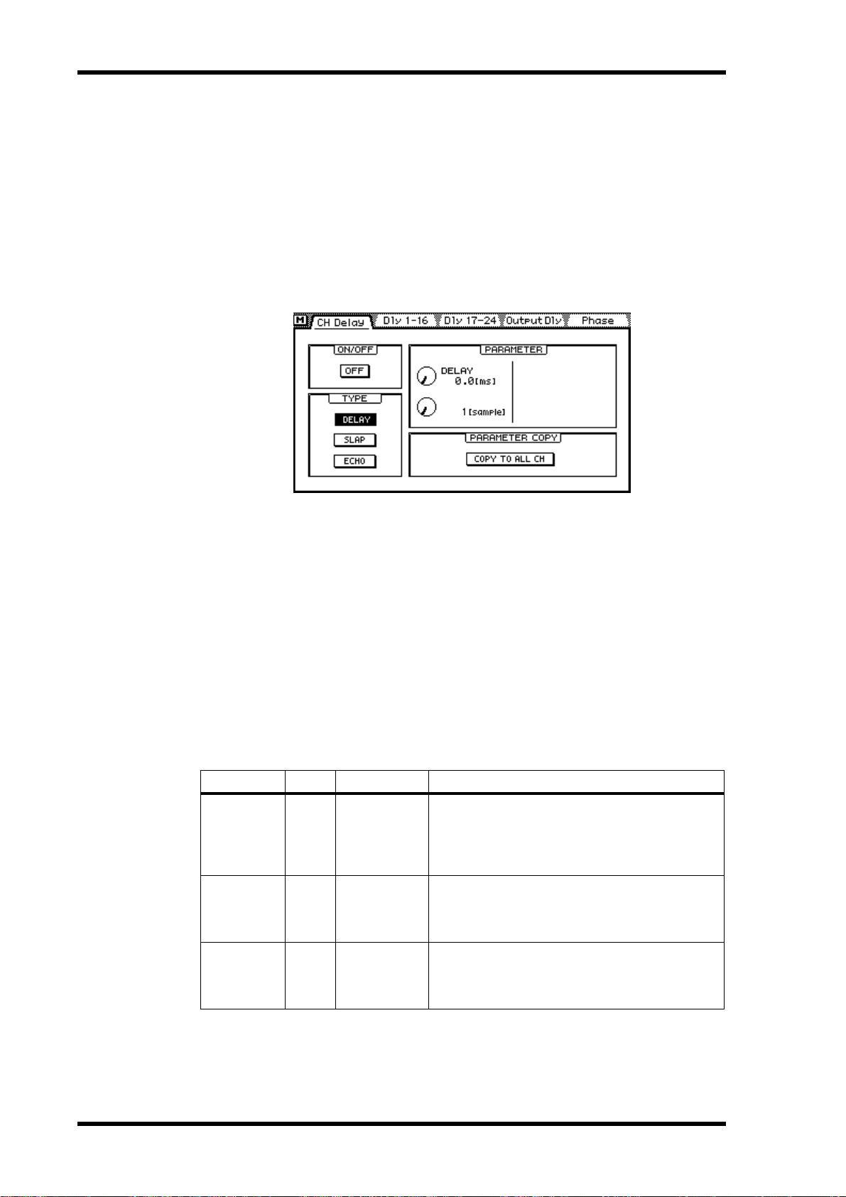
40 Chapter 4—Input Channels
Channel Delay
The Delay function can be used to compensate for micr ophone plac ement, or simply
as a delay effect. Three types of delay are available: Dela y, Slap, and Ec ho. Delay can be
applied to input channels 1 to 24 and the stereo input channel.
When channels are co nfigur ed as a st er eo pair using the Pair function (Stereo Pairs on
page 114), the channel delays of the two channels work together , and parameter adjustments can be made with either channel selected. Y ou cannot set different parameters for
the odd and even channels.
1. Use the [DELAY/∅] button to locate the CH Delay page shown below.
2. Use the [SEL] and [MIXING LAYER] buttons to select a channel. See Mixing Layer on page 31 for more information.
3. Use the cursor buttons to select the delay parameters and the [ENTER]
button and PARAMETER wheel to set them.
If you are using a mouse, simply click the switches and drag the rotary controls.
ON/OFF—This switch is used to turn on and off the delay. W hen the cursor is located
within the P ARAMETER window , the [ENTER] button can be used to turn on and off
the delay without having to select the ON/OFF switch.
TYPE—These switches are used to select the type of delay: DELAY, SLAP, or ECHO.
The echo parameters are reset when the type of delay is changed.
PARAMETER—The c ontr ols in this window ar e delay parameter controls. The n um-
ber of controls available depends on type of delay selected.
Parameter Type Range Description
Delay can be specified in either seconds or sam-
DELAY
MIX LEVEL
FB. GAIN
DELAY
SLAP
ECHO
SLAP
ECHO
ECHO –99 to +99
9,600 samples
–100 to +100
ples. The actual delay in seconds depends on the
sampling rate. The maximum delay is 217.7 milliseconds at a sampling rate of 44.1 kHz, and 200.0
milliseconds at a sampling rate of 48 kHz.
Determines the level of delayed signal. 0 is no
delay. +50 is a 50:100 mix of delayed and dry signals. +100 is a 100:100 mix. Negative values are
the same except the delayed signal is inverted.
Determines how much of the delayed signal is fed
back into the delay. 0 is no feedback. +99 is maximum feedback. Negative values are the same
except the feedback signal is inverted.
03D—Owner’s Manual
When the type of delay is changed from Delay to either Slap or Echo, the parameters
are set as follows: Delay = 172 ms, Mix = 50%, Feedback = 18%. When the type is
changed from Slap or Echo to Delay, the parameters are set as follows: Dela y = 0 ms,
Mix = 0%, Feedback = 0%.
Page 51
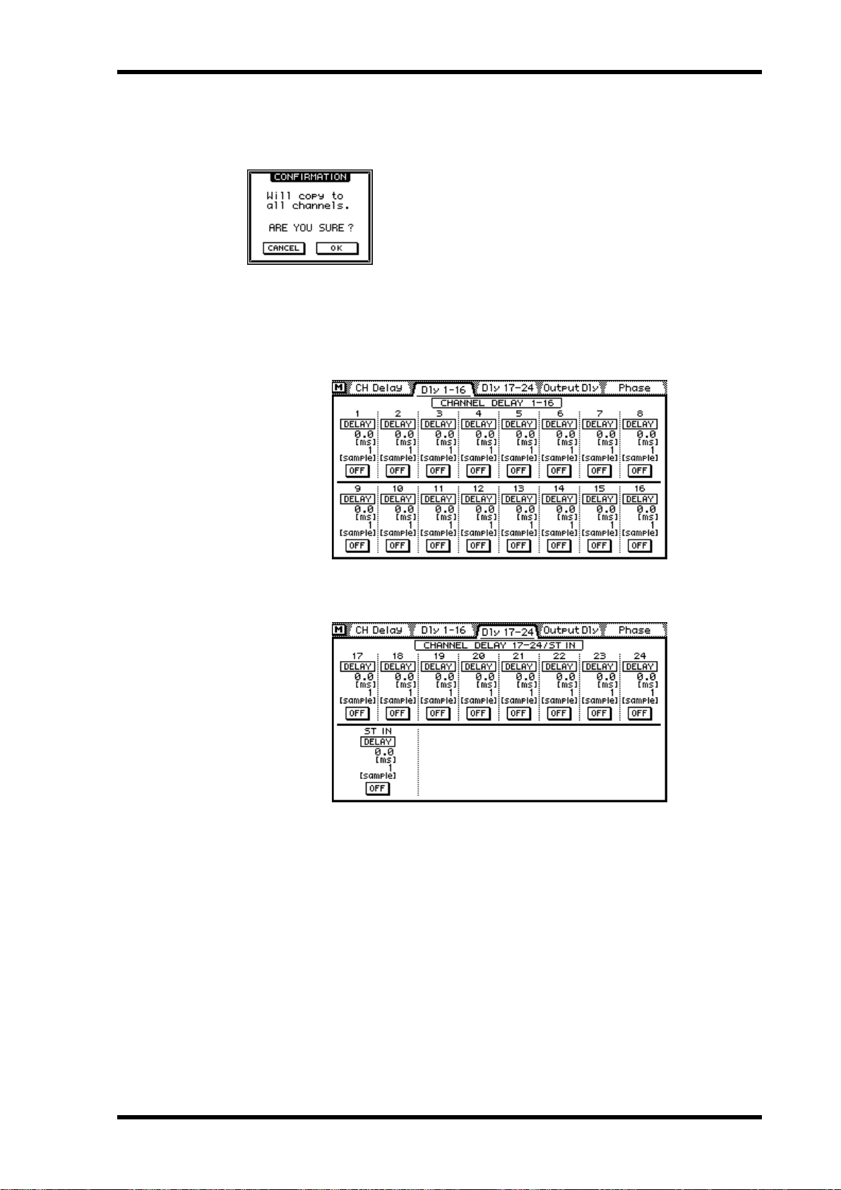
Channel Delay 41
PARAMETER COPY —The COPY T O ALL CH switch is used t o copy the delay param-
eter settings to all input channels and the stereo input channel. The following dialog
box appears when this switch is pressed.
Use OK to co p y or CANCEL t o canc el.
Viewing Channel Delay Settings
Channel delay settings can be viewed on the following two pages.
1. Use the [DELAY/∅] button to locate these pages.
The following page shows the delay settings for input channels 1 to 16.
The following page shows the delay settings for input channels 17 to 24 and the stereo
input channel.
These pages show the type of delay and delay time set for each channel. These settings
cannot be changed on these pages. The delays can, however, be turned on and off.
2. Use the [SEL] buttons to select channels and the [ENTER] button to turn
the delays on and off.
If you are using a mouse, simply click the switches. The switc hes can also be selected
using the cursor buttons.
03D—Owner’s Manual
Page 52

42 Chapter 4—Input Channels
Applying EQ to the Input Channels EQ
Each input channel features four-band parametric EQ. See EQ on page 45 for mor e
information.
Dynamics Processor
Each input channel features a dynamics processor. See Dynamics Processors on page
143 for more information.
Muting Input Channels (ON/OFF)
Channels can be muted using the [ON] buttons. These butt ons c ontain an
ON
indicator that lights up when a channel is on. The function of each [ON] button depends on the selected Mixing Laye r. See ON Buttons on page 31 for more
information.
When the [SOLO] function is on, the [ON] buttons work as solo buttons, not mute
buttons.
When channels are co nfigur ed as a st er eo pair using the Pair function (Stereo P airs on
page 114), the [ON] buttons of the two channels work together, and either button can
be used to switch the pair on and off.
Channels can also be grouped for multiple mute control using only one [ON] button.
See Mute Groups on page 113 for more information.
Setting Input Channel Levels
Input channel and stereo input channel levels ar e controlled using the faders.
The function of each fader depends on the selected fader mode and Mixing
6
0
5
10
20
40
60
00
Layer . See Faders on page 32 for more information. The selected fader mode
is shown on the display. See Display on page 24 for more information. The
stereo input channel fader is affected by the fader modes, but not the Mixing
Layer .
1.Press the [FADER] button.
The Meter page appears and the faders function as normal channel faders.
2.Use the [MIXING LAYER] button to select Mixing Layer 1–16
or 17–24/MASTER.
3. Use the faders to adjust the channel levels.
When channels are co nfigur ed as a st er eo pair using the Pair function (Stereo P airs on
page 114), the faders of the two channels work together, and either fader can be used to
adjust the level of the stereo pair.
Pan, Balance & Routing
03D—Owner’s Manual
Input channel and stereo input channel signals can be routed t o buses 1 t o 4 and the
Stereo bus. Input c hannel signals can be panned. Stereo input channel signals can be
balanced and panned. Ster eo input channel pan can be used t o adjust the width of stereo signals. P an, balance, and routing settings are made on the Pan/Rout e pages. See
Stereo Pan, Balance & Routing on page 59 for more information.
Page 53
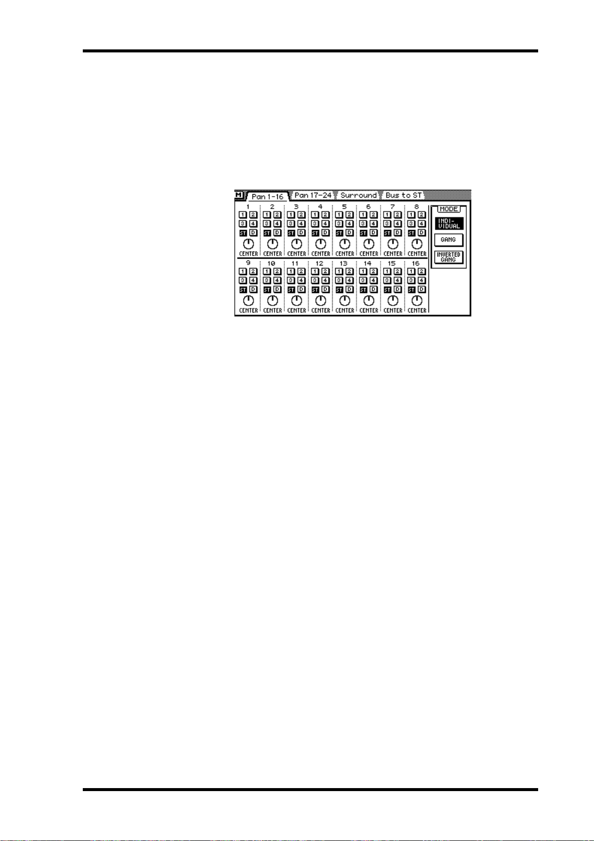
Direct Outputs 43
Direct Outputs
Up to eight post-fader signals from input channels 1 to 16 can be output directly via the
YGDAI digital outputs. Direct out settings are made on the Pan/Route page. When a
channel is set for direct out operation, the YGDAI OUTPUT ASSIGN for that channel
is set automatically on the D .out Setup page. These settings can also be made manually.
See Assigning Signals to the YGDAI Outputs on page 224 for more information.
1. Use the [PAN/ROUTING] button to locate the page shown below.
2. Use the [SEL] buttons to select an input channel from 1 to 16.
3. Use the cursor buttons to select the (D)irect out switches and the [ENTER]
button to set them.
If you are using a mouse, simply click the (D)irect out switches.
Aux Sends
Input channel and stereo input channel signals can be sent to aux sends 1 to 4. Channel
sends can be configured as either pre-fader or post-fader sends. See Aux Sends on page
89 for more information.
When aux sends are configur ed as a ster eo pair, aux send pan controls are activated on
the input channels, stereo input c hannel, and effects r eturns. See A ux Send Stereo P airs
on page 94 for more information.
Monitoring Input Channels
See Solo, Monitors & Meters on page 71 for mor e information.
Input Channel Stereo Pairs
Odd and even input channels from 1 to 24 can be paired for ster eo operation. This
makes it easy to work with stereo input signals, because you only need to adjust one
input channel to control both the left and right channels of the stereo signal. Only adjacent odd and even input channels can be paired (i.e., 1/2, 3/4, 5/6, not 2/3 or 4/5). W ith
24 input channels, up to 12 ster eo input pairs ar e possible. Input channel stereo pairs
are configured on the Pair page. See Stereo Pairs on page 114 for more information.
When two input channels are pair ed, the following parameters are linked: channel
delay, EQ, att enuat ors, dynamics processors, [ON] buttons, solo, channel faders,
pre/post settings for the aux sends and effects sends, aux and effects send faders, and
routing switches. Pan operation depends on the selected pan mode. See Pan Mode on
page 60 for more information.
03D—Owner’s Manual
Page 54

44 Chapter 4—Input Channels
Input Channels Block Diagram
INPUT
ST IN
DIGITAL
STEREO
IN
1, 2
IN
1, 2
INSERT
3-8
3-8
9-16
This section is available only when
an optional YGDAI card is inserted.
L
R
COAXIAL
AES/EBU
PHANTOM
PAD
26dB
PHANTOM
PAD
26dB
CH INPUT
17-24
GAIN
SELECT
+48V
INPUT
(YGDAI)
AD
AD
Emphasis
DC CUTAD
DC CUT
DC CUTAD
DC CUT
De-
HA
GAIN
+48V
HA
GAIN
HA
GAIN
HA AD DC CUT
HA
De-
Emphasis
FLIP
Meter
Meter
Meter
ST
SOLO
AUX
1 2 3 4
EFF
L R
L R
1 2
DIRECT OUT
BUS
MeterMeter
Meter
4Band
DELAY
ATT
Same as 1, 2
Same as 1, 2
Same as 1, 2
ATT
DELAY/
EFFECT
ATT
DELAY/
EFFECT
Dynamics
PEQ
Meter Meter
4Band
PEQ
4Band
PEQ
PAN: INDIVIDUAL/GANG/INVERTED GANG
*
ON
Meter
Dynamics
ON
Dynamics
CH Fader
BALANCE
Meter
AUX/EFF
PRE/POST
ST IN
Fader
ON/OFF
Meter
ST CASCADE IN
PAN
AUX 1
AUX 2
AUX 3
AUX 4
EFF 1
EFF 2
*
AUX 1
AUX 2
AUX 3
AUX 4
EFF 1
EFF 2
1 2 3 4
PAN
03D—Owner’s Manual
Page 55

EQ 45
EQ
5
In this chapter...
About 03D EQ . . . . . . . . . . . . . . . . . . . . . . . . . . . . . . . . . . . . . . . . . . . . . . . . . . . . 46
Adjusting the EQ . . . . . . . . . . . . . . . . . . . . . . . . . . . . . . . . . . . . . . . . . . . . . . . . . . 47
Bypassing the EQ . . . . . . . . . . . . . . . . . . . . . . . . . . . . . . . . . . . . . . . . . . . . . . . . . 47
Resetting the EQ Gain Controls . . . . . . . . . . . . . . . . . . . . . . . . . . . . . . . . . . . . . 47
EQ Library . . . . . . . . . . . . . . . . . . . . . . . . . . . . . . . . . . . . . . . . . . . . . . . . . . . . . . . 48
Storing EQ Programs . . . . . . . . . . . . . . . . . . . . . . . . . . . . . . . . . . . . . . . . . . . . . . 49
Recalling EQ Programs . . . . . . . . . . . . . . . . . . . . . . . . . . . . . . . . . . . . . . . . . . . . 50
Editing EQ Program Titles . . . . . . . . . . . . . . . . . . . . . . . . . . . . . . . . . . . . . . . . . 51
Preset EQ Pr ograms . . . . . . . . . . . . . . . . . . . . . . . . . . . . . . . . . . . . . . . . . . . . . . . 52
03D—Owner’s Manual
Page 56

46 Chapter 5—EQ
About 03D EQ
03D EQ is four-band fully parametric, with variable gain, frequency, Q, and ON/OFF
parameters. EQ is available on all input channels, the stereo input channel, the stereo
output, bus outputs, aux sends, and the onboar d effects returns. See the Block Diagram
on page 21 for the exact location of each EQ section. Initially, each EQ section is configured as a conv entional four-band EQ, with shelving high and low and peaking
lo-mid and hi-mid. Ho wever, the low band can be configured for shelving, peaking, or
HPF (High-Pass Filter) operation, while the hi band can be c o nfigur ed for shel ving,
peaking, or LPF (Low-P ass Filt er) operation.
When channels are co nfigur ed as a st er eo pair using the Pair function (Stereo P airs on
page 114), the EQ sections, including att en uat ors, of the two channels work together,
and parameter adjustments can be made with either channel selected. You cannot set
different parameters for the odd and even channels.
EQ settings can be stored as programs in the EQ library. The EQ library contains 40
preset programs and 40 user programs. See EQ Library on page 48 for more information. EQ settings are also stored in scene memories (page 164) and the channel library
(page 104).
EQ is controlled from the EQ page shown below.
The top half of the EQ page shows the EQ curve for the selected channel. The bottom
half contains the EQ controls.
03D—Owner’s Manual
Page 57

Adjusting the EQ 47
Adjusting the EQ
1. Use the [SEL] and [MIXING LAYER] buttons to select a channel. See Mixing Layer on page 31 for more information.
2. Use the [EQ LOW], [LO-MID], [HI-MID], or [HIGH] button to access the
EQ page shown below.
3. Use the [EQ LOW], [LO-MID], [HI-MID], and [HIGH] buttons to select the
EQ parameters and the PARAMETER wheel to adjust them.
Repeated pressing of the [EQ LO W], [L O-MID], [HI-MID], and [HIGH] button cycles
through the gain, frequency, and Q parameters of the respective band, allowing quick
and easy EQ adjustments.
You can also use the cursor buttons to select EQ parameters. If you are using a mouse,
position the mouse cursor over a control, press and hold the left mouse button, and
then drag the mouse.
The following table lists the EQ specs.
Low Lo-Mid Hi-Mid High
Gain
Frequency
Q
1. The Low and High gain controls work as filter on/off switches when the HPF and LPF
filters are selected using the Q control.
2. This is the frequency range for sampling rates of 44.1 kHz and 48 kHz. At a sampling
rate of 32 kHz the range is 21 Hz–15.1 kHz (115 steps).
HPF, 10.0–0.10
(41 steps),
L.SHELF
–18.0 dB to +18.0 dB (0.5 dB steps)
21 Hz–20.1 kHz (1/12 octave steps, 120 steps)
10.0–0.10 (41 steps)
1
2
LPF, 10.0–0.10
Bypassing the EQ
To bypass the EQ for the selected channel, simply press the [ENTER] button.
Press again to turn the EQ back on. On the EQ page the [ENTER] butt on can
be used to bypass the EQ regardless of the cursor position. If you are using a
mouse, simply click the EQ ON switch on the EQ page.
(41 steps),
H.SHELF
Resetting the EQ Gain Controls
To reset the EQ gain controls for the selected channel, pr ess the EQ [HI-MID] and
[HIGH] buttons together. The frequency and Q contr ols ar e not reset.
03D—Owner’s Manual
Page 58

48 Chapter 5—EQ
EQ Library
EQ settings can be stored as programs in the EQ library. The EQ library contains 40
preset programs (1–40) and 40 user programs (41–80). U ser programs allow you to
store frequently used EQ settings, and they can be titled for easy identification. The EQ
library can also be used to transfer settings from one EQ to another. For example, the
stereo out EQ settings could be stored as a library program and then recalled to an aux
send EQ. The unique collection of preset EQ programs are designed for specific applications and instruments, and provide a good referenc e and starting point when making
EQ adjustments. See page 52 for a complete list of the preset EQ programs.
The EQ library is controlled from the Library page shown below. P r ess the [EQ L OW]
and [LO-MID] buttons together to ac c ess the Library page. I f you are using a mouse
and the EQ page is already shown, simply click the Library page title tab.
The top half of the Library page shows the EQ curve and signal levels for the selected
channel. The bottom half contains the EQ library functions.
03D—Owner’s Manual
Page 59

Storing EQ Programs 49
Storing EQ Programs
EQ programs are stored on the EQ Library page. You can store EQ settings t o user programs 41 to 80. Preset pr ograms 1 to 40 are r ead only.
1. Press the [EQ LOW] and [LO-MID] buttons together to access the Library
page.
2. Use the [SEL] buttons to select the channel whose EQ settings you want
to store as a program.
3. Use the PARAMETER wheel to scroll through the list of EQ programs. If
you are using a mouse, position the mouse cursor over the parameter
box, press and hold the left mouse button, and then drag the mouse.
As each program is selected, its EQ curve appears in the EQ CURVE window. EQ programs that do not contain data have the title No Data!
4. Use the cursor button to select the STORE switch, and then press the
[ENTER] button.
If you are using a mouse, simply click the ST ORE switch.
The Title Edit dialog box appears.
5. Enter a title for the EQ program.
See Title Edit Dialog Box on page 33 for more information.
6. Press OK on the Title Edit dialog box.
The EQ program is stored.
03D—Owner’s Manual
Page 60

50 Chapter 5—EQ
Recalling EQ Programs
EQ programs are recalled from the EQ Library page. You can recall an y of the 40 preset
and 40 user programs.
1. Press the [EQ LOW] and [LO-MID] buttons together to access the Library
page.
2. Use the [SEL] buttons to select the channel to which you want to recall
the EQ program.
3. Use the PARAMETER wheel to scroll through the list of EQ programs. If
you are using a mouse, position the mouse cursor over the parameter
box, press and hold the left mouse button, and then drag the mouse.
As each program is selected, its EQ curve appears in the EQ CURVE window. EQ programs that do not contain data have the title No Data!
4. Use the cursor button to select the RECALL switch, and then press the
[ENTER] button.
If you are using a mouse, simply click the RECALL switch.
The EQ program is recalled.
03D—Owner’s Manual
Page 61

Editing EQ Program Titles 51
Editing EQ Program Titles
EQ program titles can be edited at anytime. You don’t ha v e t o r ecall a program to edit
its title. Only EQ programs that contain data can hav e their titles edited. T itle editing is
performed on the EQ Library page shown below.
1. Press the [EQ LOW] and [LO-MID] buttons together to access the Library
page.
2. Select the EQ program using the PARAMETER wheel or mouse.
3. Use the cursor buttons to select the TITLE EDIT switch, and then press
the [ENTER] button.
If you are using a mouse, simply click the TITLE EDIT switch.
The Title Edit dialog box appears.
4. Edit the program title.
See Title Edit Dialog Box on page 33 for more information.
5. When you’ve finished, select OK and press the [ENTER] button.
If you are using a mouse, simply click the OK switch.
03D—Owner’s Manual
Page 62

52 Chapter 5—EQ
Preset EQ Programs
# Title
01 Bass Drum 1
02 Bass Drum 2
03 Snare Drum 1
04 Snare Drum 2
05 Tom-tom 1
06 Cymbal
07 High Hat
08 Percussion
09 E.Bass 1
10 E.Bass 2
Parameter
LOW L-MID H-MID HIGH
PEAKING PEAKING PEAKING H.SHELF
G
+3.5 dB –3.5 dB 0.0 dB +4.0 dB
F
99 Hz 265 Hz 1.05 kHz 5.33 kHz
Q
G
F
Q
G
F
Q
G
F
Q
G
F
Q
G
F
Q
G
F
Q
G
F
Q
G
F
Q
G
F
Q
1.2 10 0.9 —
PEAKING PEAKING PEAKING LPF
+8.0 dB –7.0 dB +6.0 dB ON
79 Hz 397 Hz 2.52 kHz 12.6 kHz
1.4 4.5 2.2 —
PEAKING PEAKING PEAKING H.SHELF
–0.5 dB 0.0 dB +3.0 dB +4.5 dB
132 Hz 1.00 kHz 3.17 kHz 5.04 kHz
1.2 4.5 0.11 —
L.SHELF PEAKING PEAKING PEAKING
+1.5 dB –8.5 dB +2.5 dB +4.0 dB
177 Hz 334 Hz 2.37 kHz 4.00 kHz
— 10 0.7 0.1
PEAKING PEAKING PEAKING PEAKING
+2.0 dB –7.5 dB +2.0 dB +1.0 dB
210 Hz 667 Hz 4.49 kHz 6.35 kHz
1.4 10 1.2 0.28
L.SHELF PEAKING PEAKING H.SHELF
–2.0 dB 0.0 dB 0.0 dB +3.0 dB
105 Hz 420 Hz 1.05 kHz 13.4 kHz
— 8 0.9 —
L.SHELF PEAKING PEAKING H.SHELF
–4.0 dB –2.5 dB +1.0 dB +0.5 dB
94 Hz 420 Hz 2.82 kHz 7.55 kHz
— 0.5 1 —
L.SHELF PEAKING PEAKING H.SHELF
–4.5 dB 0.0 dB +2.0 dB 0.0 dB
99 Hz 397 Hz 2.82 kHz 16.9 kHz
— 4.5 0.56 —
L.SHELF PEAKING PEAKING H.SHELF
–7.5 dB +4.5 dB +2.5 dB 0.0 dB
35 Hz 111 Hz 2.00 kHz 4.00 kHz
— 5 4.5 —
PEAKING PEAKING PEAKING H.SHELF
+3.0 dB 0.0 dB +2.5 dB +0.5 dB
111 Hz 111 Hz 2.24 kHz 4.00 kHz
0.1 5 6.3 —
Description
Emphasizes the low
range of a bass drum
and the attack created
by the beater.
Creates a peak around
80Hz, producing a
tight, stiff sound.
Emphasizes snapping
and rimshot sounds.
Emphasizes the ranges
of that classic rock snare
drum sound.
Emphasizes the attack of
tom-toms, and creates a
long, “leathery” decay.
Emphasizes the attack of
crash cymbals, extending the “sparkling”
decay.
Use on a tight high-hat,
emphasizing the mid to
high range.
Emphasizes the attack
and clarifies the
high-range of instruments, such as shakers,
cabasas, and congas.
Makes a tight electric
bass sound by cutting
very low frequencies.
Unlike program 9, this
program emphasizes
the low range of an
electric bass.
03D—Owner’s Manual
Page 63

Preset EQ Programs 53
# Title
11 Syn.Bass 1
12 Syn.Bass 2
13 Piano 1
14 Piano 2
15 E.G.Clean
16 E.G.Crunch 1
17 E.G.Crunch 2
18 E.G.Dist. 1
19 E.G.Dist. 2
20 A.G.Stroke 1
Parameter
LOW L-MID H-MID HIGH
PEAKING PEAKING PEAKING H.SHELF
G
+3.5 dB +8.5 dB 0.0 dB 0.0 dB
F
83 Hz 944 Hz 4.00 kHz 12.6 kHz
Q
G
Q
G
Q
G
Q
G
Q
G
Q
G
Q
G
Q
G
Q
G
Q
0.1 8 4.5 —
PEAKING PEAKING PEAKING H.SHELF
+2.5 dB 0.0 dB +1.5 dB 0.0 dB
F
125 Hz 177 Hz 1.12 kHz 12.6 kHz
1.6 8 2.2 —
L.SHELF PEAKING PEAKING H.SHELF
–6.0 dB 0.0 dB +2.0 dB +4.0 dB
F
94 Hz 944 Hz 3.17 kHz 7.55 kHz
— 8 0.9 —
PEAKING PEAKING PEAKING H.SHELF
+3.5 dB –8.5 dB +1.5 dB +3.0 dB
F
223 Hz 595 Hz 3.17 kHz 5.33 kHz
5.6 10 0.7 —
PEAKING PEAKING PEAKING H.SHELF
+2.0 dB –5.5 dB +0.5 dB +2.5 dB
F
265 Hz 397 Hz 1.33 kHz 4.49 kHz
0.18 10 6.3 —
PEAKING PEAKING PEAKING PEAKING
+4.5 dB 0.0 dB +4.0 dB +2.0 dB
F
140 Hz 1.00 kHz 1.88 kHz 5.65 kHz
8 4.5 0.63 9
PEAKING PEAKING PEAKING H.SHELF
+2.5 dB +1.5 dB +2.5 dB 0.0 dB
F
125 Hz 445 Hz 3.36 kHz 19.0 kHz
8 0.4 0.16 —
L.SHELF PEAKING PEAKING H.SHELF
+5.0 dB 0.0 dB +3.5 dB 0.0 dB
F
354 Hz 944 Hz 3.36 kHz 12.6 kHz
— 9 10 —
L.SHELF PEAKING PEAKING H.SHELF
+6.0 dB –8.5 dB +4.5 dB +4.0 dB
F
315 Hz 1.05 kHz 4.23 kHz 12.6 kHz
—10 4 —
PEAKING PEAKING PEAKING H.SHELF
–2.0 dB 0.0 dB +1.0 dB +4.0 dB
F
105 Hz 1.00 kHz 1.88 kHz 5.33 kHz
0.9 4.5 3.5 —
Description
Use on a synth bass with
emphasized low range.
Emphasizes the attack
that is peculiar to a
synth bass.
This is used to make a
piano sound brighter.
Used in conjunction
with a compressor, this
program emphasizes
the attack and low
range of a piano sound.
Use for line-recording
an electric guitar or
semi-acoustic guitar to
get a slightly hard
sound.
Adjusts the tonal quality of a slightly distorted
guitar sound.
A variation on program
16.
Makes a heavily distorted guitar sound
clearer.
A variation on program
18.
Emphasizes the bright
tones of an acoustic guitar.
03D—Owner’s Manual
Page 64
54 Chapter 5—EQ
# Title
21 A.G.Stroke 2
22 A.G.Arpeg. 1
23 A.G.Arpeg. 2
24 Brass Sec.
25 Male Vocal 1
26 Male Vocal 2
27 Female Vo. 1
28 Female Vo. 2
29 Chorus&Harmo
30 Total EQ 1
Parameter
LOW L-MID H-MID HIGH
L.SHELF PEAKING PEAKING H.SHELF
G
–3.5 dB –2.0 dB 0.0 dB +2.0 dB
F
297 Hz 749 Hz 2.00 kHz 3.56 kHz
Q
G
F
Q
G
F
Q
G
F
Q
G
F
Q
G
F
Q
G
F
Q
G
F
Q
G
F
Q
G
F
Q
— 9 4.5 —
L.SHELF PEAKING PEAKING PEAKING
–0.5 dB 0.0 dB 0.0 dB +2.0 dB
223 Hz 1.00 kHz 4.00 kHz 6.72 kHz
— 4.5 4.5 0.12
L.SHELF PEAKING PEAKING H.SHELF
0.0 dB –5.5 dB 0.0 dB +4.0 dB
177 Hz 354 Hz 4.00 kHz 4.23 kHz
— 7 4.5 —
PEAKING PEAKING PEAKING PEAKING
–2.0 dB –1.0 dB +1.5 dB +3.0 dB
88 Hz 841 Hz 2.11 kHz 4.49 kHz
2.8 2 0.7 7
PEAKING PEAKING PEAKING PEAKING
–0.5 dB 0.0 dB +2.0 dB +3.5 dB
187 Hz 1.00 kHz 2.00 kHz 6.72 kHz
0.11 4.5 0.56 0.11
PEAKING PEAKING PEAKING H.SHELF
+2.0 dB –5.0 dB –2.5 dB +4.0 dB
167 Hz 236 Hz 2.67 kHz 6.72 kHz
0.11 10 5.6 —
PEAKING PEAKING PEAKING PEAKING
–1.0 dB +1.0 dB +1.5 dB +2.0 dB
118 Hz 397 Hz 2.67 kHz 5.99 kHz
0.18 0.45 0.56 0.14
L.SHELF PEAKING PEAKING H.SHELF
–7.0 dB +1.5 dB +1.5 dB +2.5 dB
111 Hz 334 Hz 2.00 kHz 6.72 kHz
— 0.16 0.2 —
PEAKING PEAKING PEAKING PEAKING
–2.0 dB –1.0 dB +1.5 dB +3.0 dB
88 Hz 841 Hz 2.11 kHz 4.49 kHz
2.8 2 0.7 7
PEAKING PEAKING PEAKING H.SHELF
–0.5 dB 0.0 dB +3.0 dB +6.5 dB
94 Hz 944 Hz 2.11 kHz 16.0 kHz
7 2.2 5.6 —
Description
A variation on program
20. You can also use it
with a gutsy guitar
sound.
Corrects arpeggio technique of an acoustic guitar.
A variation on program
22.
Use with trumpets,
trombones, or sax. With
one instrument, adjust
the HIGH or H-MID frequency.
Use as a template for
male vocal. Adjust the
HIGH or H-MID setting
according to the voice
quality.
A variation on program
25.
Use as a template for
female vocal. Adjust the
HIGH or H-MID setting
according to the voice
quality.
A variation on program
27.
Use as a template for a
chorus. It makes the
entire chorus much
brighter.
Use on a stereo mix during mixdown. Sounds
even better when used
with a compressor.
03D—Owner’s Manual
Page 65

Preset EQ Programs 55
# Title
31 Total EQ 2
32 Total EQ 3
33 Bass Drum 3
34 Snare Drum 3
35 Tom-tom 2
36 Piano 3
37 Piano Low
38 Piano High
39 Fine-EQ Cass
40 Narrator
Parameter
LOW L-MID H-MID HIGH
PEAKING PEAKING PEAKING H.SHELF
G
+4.0 dB +1.5 dB +2.0 dB +6.0 dB
F
94 Hz 749 Hz 1.78 kHz 17.9 kHz
Q
G
F
Q
G
F
Q
G
F
Q
G
F
Q
G
F
Q
G
F
Q
G
F
Q
G
F
Q
G
F
Q
7 2.8 5.6 —
L.SHELF PEAKING PEAKING H.SHELF
+1.5 dB +0.5 dB +2.0 dB +4.0 dB
66 Hz 841 Hz 1.88 kHz 15.1 kHz
— 0.28 0.7 —
PEAKING PEAKING PEAKING PEAKING
+3.5 dB –10.0 dB +3.5 dB 0.0 dB
118 Hz 315 Hz 4.23 kHz 20.1 kHz
2 10 0.4 0.4
L.SHELF PEAKING PEAKING PEAKING
0.0 dB +2.0 dB +3.5 dB 0.0 dB
223 Hz 561 Hz 4.23 kHz 4.00 kHz
— 4.5 2.8 0.1
L.SHELF PEAKING PEAKING H.SHELF
–9.0 dB +1.5 dB +2.0 dB 0.0 dB
88 Hz 210 Hz 5.33 kHz 16.9 kHz
— 4.5 1.2 —
PEAKING PEAKING PEAKING H.SHELF
+4.5 dB –13.0 dB +4.5 dB +2.5 dB
99 Hz 472 Hz 2.37 kHz 10.0 kHz
8109—
PEAKING PEAKING PEAKING H.SHELF
–5.5 dB +1.5 dB +6.0 dB 0.0 dB
187 Hz 397 Hz 6.72 kHz 12.6 kHz
10 6.3 2.2 —
PEAKING PEAKING PEAKING PEAKING
–5.5 dB +1.5 dB +5.0 dB +3.0 dB
187 Hz 397 Hz 6.72 kHz 5.65 kHz
10 6.3 2.2 0.1
L.SHELF PEAKING PEAKING H.SHELF
–1.5 dB –18.0 dB +1.0 dB +3.0 dB
74 Hz 1.00 kHz 4.00 kHz 12.6 kHz
— 4.5 1.8 —
PEAKING PEAKING PEAKING H.SHELF
–4.0 dB –1.0 dB +2.0 dB 0.0 dB
105 Hz 707 Hz 2.52 kHz 10.0 kHz
4 7 0.63 —
Description
A variation on program
30.
A variation on program
30. Can also be used
with stereo inputs or
external effect returns.
A variation on program
1. The low and mid
range is removed.
A variation on program
3. It creates a thick
sound.
A variation on program
5. Emphasizes the mid
and high range.
A variation on program
13.
Use for the low range of
a piano sound recorded
in stereo.
Use for the high range
of a piano sound
recorded in stereo.
Use when recording to
or from cassette tape to
make the sound clearer.
Use when recording
narration.
03D—Owner’s Manual
Page 66

56 Chapter 5—EQ
03D—Owner’s Manual
Page 67

Pan, Routing & Surround Pan 57
Pan, Routing & Surround Pan
6
In this chapter...
Selecting a Pan M ode . . . . . . . . . . . . . . . . . . . . . . . . . . . . . . . . . . . . . . . . . . . . . . 58
Stereo P an, Balance & Routing . . . . . . . . . . . . . . . . . . . . . . . . . . . . . . . . . . . . . . 59
Stereo Pairs, Pan & Routing . . . . . . . . . . . . . . . . . . . . . . . . . . . . . . . . . . . . . . . . . 61
Surround Pan . . . . . . . . . . . . . . . . . . . . . . . . . . . . . . . . . . . . . . . . . . . . . . . . . . . . 62
Using Surround Pan . . . . . . . . . . . . . . . . . . . . . . . . . . . . . . . . . . . . . . . . . . . . . . . 65
03D—Owner’s Manual
Page 68

58 Chapter 6—Pan, Routing & Surround Pan
Selecting a Pan Mode
In addition to stereo pan, the 03D features three surround pan modes. Pan modes are
set on the Surround page.
1. Use the [PAN/ROUTING] button to locate the Surround page shown
below.
2. Use the cursor buttons to select a pan mode.
3. Press the [ENTER] button to activate the selected pan mode.
If you are using a mouse, simply click a Pan mode switch.
When a surround pan mode is selected, the B us t o ST page title tab is r eplac ed b y the
Surr. 1–16 and Surr . 17–24 surround pan page title tabs, as shown below . The B us to ST
page is available only when stereo pan mode is selected.
Stereo pan mode is explained in Stereo Pan, Balance & Routing on page 59.
The surround pan modes are explained in Surround Pan on page 62.
03D—Owner’s Manual
Page 69

Stereo Pan, Balance & Routing 59
Stereo Pan, Balance & Routing
Input channel, ster eo input channel, and effects return signals can be routed t o buses 1
to 4 and the Stereo bus. I nput channel signals can be panned. St ereo input channel and
effects return signals can be balanced and panned. This pan can be used to adjust the
width of stereo signals. Pan, balanc e, and routing settings are made on the Pan/Route
pages.
1. Use the [PAN/ROUTING] button to locate the pages shown below.
The following page contains the pan and routing parameters for input channels 1 to 16.
The following page contains the pan and routing parameters for input channels 17 to
24, the stereo input channel, and effects returns.
2. Use the [SEL] and [MIXING LAYER] buttons to select a channel. See Mixing Layer on page 31 for more information.
3. Use the cursor buttons to select parameters and the [ENTER] button and
PARAMETER wheel to set them.
If you are using a mouse, simply click the bus routing switches. For pan and balance,
position the mouse cursor over a pan control, press and hold the left mouse button, and
then drag the mouse.
Pan & Balance
Input channels 1 to 24 use a single pan control to pan signals between the
left and right stereo buses, and odd and even buses.
The stereo input channel and effects returns hav e two pan contr ols: one for
the left signal and one for the right. These pan controls can be used to adjust
the width of stereo signals.
With the left control set at L16 and the right contr ol set at R16, as shown,
the width of a stereo signal is 100%.
03D—Owner’s Manual
Page 70

60 Chapter 6—Pan, Routing & Surround Pan
With both controls set at CENTER, as sho wn, the width of a stereo signal is
reduced to zero, and it’s fed to the buses in mono.
Setting the controls to positions in between these two extr emes allo ws you
set the width of the stereo signal. To maintain a central balance, however,
you must set both controls to c o rresponding values. For example, L5 and
R5, or L10 and R10.
The stereo input channel and effects returns hav e balance controls. The balance control can be used to balance the lev els of the left and right signals.
They does not affect the width of a stereo signal.
Including center, there are 33 pan and balance positions.
Left
L16←L15←···←L2←L1← CENTER →R1→R2→···→R15→R16
Center
Right
Pan Mode
The MODE switches, which are c ommon t o the Pan 1–16, Pan 17–24, and Bus t o ST
pages, are used to set the pan mode for the ster eo input c hannel, st er eo effects r eturns,
and input channels that are configured as ster eo pairs.
In this mode, pan contr ols can be adjust ed indi vidually.
In this mode, pan contr ols ar e ganged t ogether.
In this mode, pan contr ols ar e ganged t ogether but operation is in verted
(i.e., pan controls mo v e in opposit e directions).
Routing
03D—Owner’s Manual
A highlighted routing switch indicates that a channel is routed to a bus.
Input channels 1 to 16 have four bus r outing switches (1, 2, 3, 4), a st ereo routing switch (ST), and a direct out switch (D). See page 43 for information about
the direct output switch.
Input channels 17 to 24, the st ereo input c hannel, and the effects returns ha v e
four bus routing switches (1, 2, 3, 4) and one stereo r outing switch (ST).
Routing switches are joined into one when bus outs are c onfigur ed as st er eo
pairs, as shown here. See Configuring Stereo Pairs on page 114 for more information.
Page 71
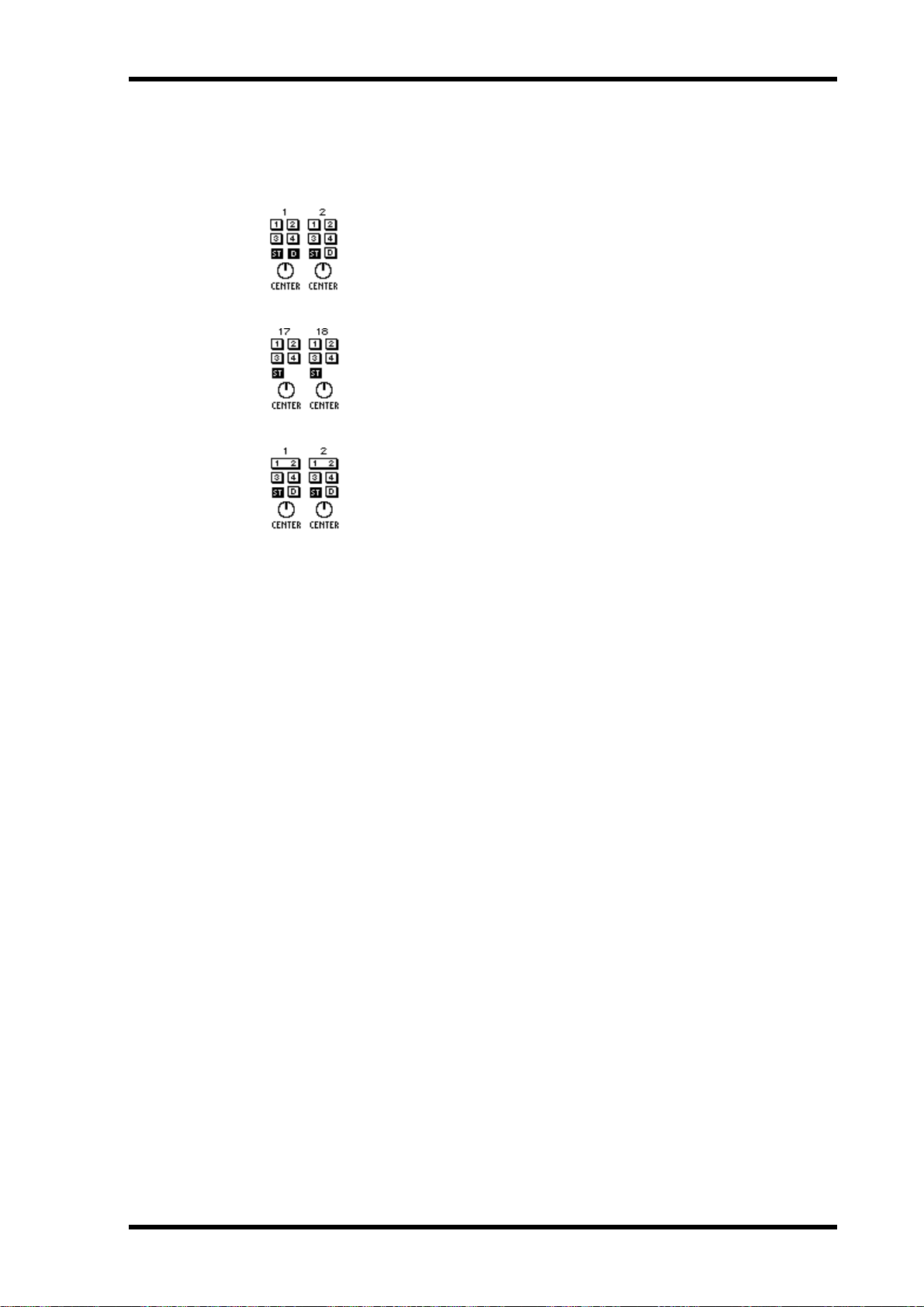
Stereo Pairs, Pan & Routing 61
Stereo Pairs, Pan & Routing
When input channels are co nfigur ed as a st er eo pair using the Pair function (Stereo
Pairs on page 114), control operation changes.
Here input channels 1 and 2 hav e been c onfigured as a st ereo pair. Clicking a routing switch on either channel sets the routing for both channel.
The operation of the two pan controls depends on the selected pan mode.
See Pan Mode on page 60 for mor e information.
Here input channels 17 and 18 have been configured as a stereo pair.
Operation is the same as for input channels 1 and 2 shown above exc ept
there is no direct output switch.
Routing switches are joined into one when bus outs are c onfigured as stereo pairs, as shown here. See Configuring Stereo Pairs on page 114 for
more information.
03D—Owner’s Manual
Page 72
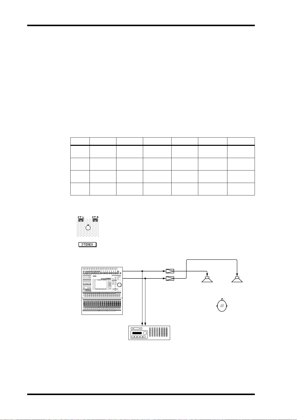
62 Chapter 6—Pan, Routing & Surround Pan
Surround Pan
As well as normal stereo pan, the 03D featur es three surround pan modes: 2+2, 3+1,
and 3+2+1. In conjunction with the stereo out and bus outs, surround pan controls
allow you to pan channel signals in a two-dimensional space. Surround pan controls
can be used to move sounds in a circular motion, ellipse, semicircle, or straight line.
Sounds can also be moved around the two-dimensional spac e using a mouse.
Surround pan modes are selected on the Surround page. See Selecting a Pan Mode on
page 58 for more information.
Output Assignments
The following table shows how the surround channels are assigned to the 03D outputs
for each surround pan mode. Connect the outputs that c orrespond t o the surround
mode you are using to a surround sound monitoring system or rec or d er.
Mode ST-L ST-R BUS 1 BUS 2 BUS 3 BUS 4
Stereo
2+2
3+1
3+2+1
L
(left)
FL
(front left)FR(front right)
L
(left)
FL
(front left)FR(front right)FC(front center)SW(subwoofer)RL(rear left)RR(rear right)
R
(right)
R
(right)
————
——
——
RL
(rear left)RR(rear right)
C
(center)S(surround)
Stereo Mode
This is the normal stereo pan mode, with left and right front channels.
It’s not really a surround pan mode, but it’s mentioned her e for co mpleteness and to highlight the differences between the various pan
modes. See Stereo P an, Balanc e & Routing on page 59 for more infor mation. The following illustration shows a normal stereo sound system using the 03D .
4
5
6
7
8
9
10
11
12
1
2
3
PAD
26dB
26dB
26dB
26dB
26dB
–60–16
–60–16
–60–16
–60–16
–60–16
+10 –34
+10 –34
+10 –34
+10 –34
+10 –34
SCENE
MIDI
MEMORY
REMOTE
MIDI
UTILITY
DIO
SOLO SETUPGROUP/PAIR
AUTOMIX
CHANNEL CONTROL
FUNCTION
DYNAMICSDELAY/Ø PAN/ROUTING
VIEW
SEL CH
LO-MIDEQ LOW
HIGHHI-MID
EQ LIBRARY
EQ FLAT
FADER MODE
AUX 1
AUX 2
AUX 3 AUX 4
EFFECT 2
FADER EFFECT 1
STATUS
METER
MIXING LAYER
1–16
17–24/MASTER
12345678910111213141516
17 18 19 20 21 22 23 24 AUX1 AUX2 AUX3 AUX4 BUS1 BUS2 BUS3 BUS4
SEL
SEL
SEL
SEL
SELONSEL
ON
ON
ON
ON
6
6
6
6
6
6
0
0
0
0
0
0
5
5
5
5
5
5
10
10
10
10
10
10
20
20
20
20
20
20
40
40
40
40
40
40
60
60
60
60
60
60
00
00
00
00
00
00
12345678910111213141516
17 18 19 20 21 22 23 24 AUX1 AUX2 AUX3 AUX4 BUS1 BUS2 BUS3 BUS4
13
26dB
26dB
26dB
+10 –20
+10 –20
+10 –20
+10 –20
+10 –20
–60–16
–60–16
–60–16
+10
+10
+10
+10
+10
+10 –34
+10 –34
+10 –34
GAIN
GAIN
GAIN
GAIN
GAIN
USER DEFINE
SCENE MEMORY
L STEREO R
FADER
EFFECT RTNST IN13–169–12FADER 1–8
SEL
SEL
SEL
SEL
SEL
SEL
SEL
ON
ON
ON
ON
ON
ON
ON
ON
6
6
6
6
6
6
6
0
0
0
0
0
0
0
5
5
5
5
5
5
5
10
10
10
10
10
10
10
20
20
20
20
20
20
20
40
40
40
40
40
40
40
60
60
60
60
60
60
60
00
00
00
00
00
00
00
PHONES
ST OUT-L
PHONES
MONITOR
14
15
16
ST IN
OUT
SOLO/ 2TR IN
+10 –20
+10 –20
+10 –20
+10 –20
100
+10
+10
+10
+10
100
GAIN
GAIN
GAIN
GAINGAIN GAIN GAIN GAIN GAIN GAIN GAIN GAIN
LEVEL
LEVEL
SCENE MEMORYSETUP
SOLO
UNDO/
REDO
SOLO
ST OUT-R
STORE
RECALL
USER DEFINE
12
CLIP
PARAMETER
–3
34
–6
–9
–12
–15
–18
–24
ENTER
–30
–36
–42
–48
CURSOR
12
EFFECT
ST OUT
ST IN
RETURN
SEL
SEL
SEL
SEL
SEL
SEL
ON
ON
ON
ON
ON
ON
6
6
6
6
6
6
0
0
0
0
0
0
5
5
5
5
5
5
10
10
10
10
10
10
20
20
20
20
20
20
40
40
40
40
40
40
60
60
60
60
60
60
00
00
00
00
00
00
EFFECT
ST OUT
ST IN
RETURN
Amps
L
R
Recorder
03D—Owner’s Manual
Page 73

2+2 Surround Mode
The 2+2 surround pan mode uses four channels: front left, fr ont
right, rear left, and rear right. The front speakers are fed fr om the 03D
stereo output, while the r ear speak ers are fed from bus outs 3 and 4.
The following illustration shows a 2+2 surround sound system using
the 03D.
Surround Pan 63
PHONES
ST OUT-L
PHONES
4
5
6
7
8
1
2
PAD
26dB
26dB
–60–16
+10 –34
+10 –34
SCENE
MEMORY
UTILITY
DIO
CHANNEL CONTROL
DYNAMICSDELAY/Ø PAN/ROUTING
LO-MIDEQ LOW
EQ LIBRARY
FADER MODE
AUX 1
AUX 2
FADER EFFECT 1
METER
MIXING LAYER
17–24/MASTER
12345678910111213141516
17 18 19 20 21 22 23 24 AUX1 AUX2 AUX3 AUX4 BUS1 BUS2 BUS3 BUS4
SEL
SEL
ON
ON
6
6
0
0
5
5
10
10
20
20
40
40
60
60
00
00
12345678910111213141516
17 18 19 20 21 22 23 24 AUX1 AUX2 AUX3 AUX4 BUS1 BUS2 BUS3 BUS4
9
3
26dB
26dB
26dB
26dB
26dB
26dB
+10 –20
+10 –20
–60–16
–60–16
–60–16
–60–16
–60–16
+10
–60–16
1–16
+10
–60–16
+10 –34
+10 –34
+10 –34
+10 –34
+10 –34
+10 –34
GAIN
MIDI
REMOTE
MIDI
SOLO SETUPGROUP/PAIR
AUTOMIX
SCENE MEMORY
FUNCTION
VIEW
SEL CH
HIGHHI-MID
EQ FLAT
AUX 3 AUX 4
EFFECT 2
FADER
STATUS
SEL
SEL
SEL
SELONSEL
SEL
SEL
SEL
ON
ON
ON
ON
ON
ON
ON
6
6
6
6
6
6
6
6
0
0
0
0
0
0
0
0
5
5
5
5
5
5
5
5
10
10
10
10
10
10
10
10
20
20
20
20
20
20
20
20
40
40
40
40
40
40
40
40
60
60
60
60
60
60
60
60
00
00
00
00
00
00
00
00
MONITOR
10
11
12
13
14
15
16
ST IN
OUT
SOLO/ 2TR IN
+10 –20
+10 –20
+10 –20
+10 –20
+10 –20
+10 –20
+10 –20
+10
+10
GAIN
GAIN
USER DEFINE
EFFECT RTNST IN13–169–12FADER 1–8
SEL
SEL
ON
ON
6
6
0
0
5
5
10
10
20
20
40
40
60
60
00
00
100
+10
+10
+10
+10
+10
100
GAIN
GAIN
GAIN
GAIN
GAIN
GAINGAIN GAIN GAIN GAIN GAIN GAIN GAIN GAIN
LEVEL
LEVEL
SCENE MEMORYSETUP
SOLO
UNDO/
REDO
SOLO
ST OUT-R
STORE
RECALL
USER DEFINE
12
L STEREO R
CLIP
PARAMETER
–3
34
–6
–9
–12
–15
–18
–24
ENTER
–30
–36
–42
–48
CURSOR
12
EFFECT
ST OUT
ST IN
RETURN
SEL
SEL
SEL
SEL
SEL
SEL
SEL
ON
ON
ON
ON
ON
ON
ON
BUS OUT 3
6
6
6
6
6
6
6
0
0
0
0
0
0
0
5
5
5
5
5
5
5
10
10
10
10
10
10
10
20
20
20
20
20
20
20
40
40
40
40
40
40
40
BUS OUT 4
60
60
60
60
60
60
60
00
00
00
00
00
00
00
EFFECT
ST OUT
ST IN
RETURN
Recorder
In 2+2 mode, channel r outing and pan looks lik e this. The pan control and 1
and 2 routing switches can still be used to assign the channel signal to bus outs
1 and 2. The SURR switch is used to rout e the channel t o the surr ound sound
outputs.
3+1 Surround Mode
The 3+1 surround pan mode uses four channels: front left, front right,
center, and surround. The fr ont speak ers ar e fed from the 03D st er eo
output, the center speak er is fed from bus out 3, and the surround
speaker is fed from bus out 4. The follo wing illustration shows a 3+1
surround sound system using the 03D . This could be used for Dolby
Surround authoring.
Amps
FL
RL RR
FR
4
5
6
7
8
9
10
11
12
1
2
3
PAD
26dB
26dB
26dB
26dB
26dB
–60–16
–60–16
–60–16
–60–16
–60–16
+10 –34
+10 –34
+10 –34
+10 –34
+10 –34
SCENE
MIDI
MEMORY
REMOTE
MIDI
UTILITY
DIO
SOLO SETUPGROUP/PAIR
AUTOMIX
CHANNEL CONTROL
FUNCTION
DYNAMICSDELAY/Ø PAN/ROUTING
VIEW
SEL CH
LO-MIDEQ LOW
HIGHHI-MID
EQ LIBRARY
EQ FLAT
FADER MODE
AUX 1
AUX 2
AUX 3 AUX 4
EFFECT 2
FADER EFFECT 1
STATUS
METER
MIXING LAYER
1–16
17–24/MASTER
12345678910111213141516
17 18 19 20 21 22 23 24 AUX1 AUX2 AUX3 AUX4 BUS1 BUS2 BUS3 BUS4
SEL
SEL
SEL
SEL
SELONSEL
ON
ON
ON
ON
6
6
6
6
6
6
0
0
0
0
0
0
5
5
5
5
5
5
10
10
10
10
10
10
20
20
20
20
20
20
40
40
40
40
40
40
60
60
60
60
60
60
00
00
00
00
00
00
12345678910111213141516
17 18 19 20 21 22 23 24 AUX1 AUX2 AUX3 AUX4 BUS1 BUS2 BUS3 BUS4
13
26dB
26dB
26dB
+10 –20
+10 –20
+10 –20
+10 –20
+10 –20
–60–16
–60–16
–60–16
+10
+10
+10
+10
+10
+10 –34
+10 –34
+10 –34
GAIN
GAIN
GAIN
GAIN
GAIN
USER DEFINE
SCENE MEMORY
FADER
EFFECT RTNST IN13–169–12FADER 1–8
SEL
SEL
SEL
SEL
SEL
SEL
SEL
ON
ON
ON
ON
ON
ON
ON
ON
6
6
6
6
6
6
6
0
0
0
0
0
0
0
5
5
5
5
5
5
5
10
10
10
10
10
10
10
20
20
20
20
20
20
20
40
40
40
40
40
40
40
60
60
60
60
60
60
60
00
00
00
00
00
00
00
PHONES
ST OUT-L
PHONES
MONITOR
14
15
16
ST IN
OUT
SOLO/ 2TR IN
+10 –20
+10 –20
+10 –20
+10 –20
100
+10
+10
+10
+10
100
GAIN
GAIN
GAIN
GAINGAIN GAIN GAIN GAIN GAIN GAIN GAIN GAIN
LEVEL
LEVEL
SCENE MEMORYSETUP
SOLO
UNDO/
REDO
SOLO
ST OUT-R
STORE
RECALL
USER DEFINE
12
L STEREO R
CLIP
PARAMETER
–3
34
–6
–9
–12
–15
–18
–24
ENTER
–30
–36
–42
–48
CURSOR
12
EFFECT
ST OUT
ST IN
RETURN
SEL
SEL
SEL
SEL
SEL
SEL
ON
ON
ON
ON
ON
ON
BUS OUT 3
6
6
6
6
6
6
0
0
0
0
0
0
5
5
5
5
5
5
10
10
10
10
10
10
20
20
20
20
20
20
40
40
40
40
40
40
BUS OUT 4
60
60
60
60
60
60
00
00
00
00
00
00
EFFECT
ST OUT
ST IN
RETURN
Amps
L
CR
S
Recorder
03D—Owner’s Manual
Page 74

64 Chapter 6—Pan, Routing & Surround Pan
In 3+1 mode, channel r outing and pan look like this. The pan contr ol and 1 and
2 routing switches can still be used to assign the channel signal to bus outs 1 and
2. The SURR switch is used to assign the channel to the surround sound outputs.
3+2+1 Surround Mode
The 3+2+1 surround pan mode uses six channels: front left, fr ont
right, rear left, rear right, fr ont c ent er, and subwoofer. The front
speakers are fed from the 03D ster eo output, the r ear speak ers are fed
from bus outs 3 and 4, the front c ent er speaker is fed from bus out 1,
and the subwoofer is fed from bus out 2. The follo wing illustration
shows a 3+2+1 surround sound system using the 03D. This could be
used for Dolby A C-3 S urround authoring.
4
5
6
7
8
9
10
11
12
1
2
3
PAD
26dB
26dB
26dB
26dB
26dB
–60–16
–60–16
–60–16
–60–16
–60–16
+10 –34
+10 –34
+10 –34
+10 –34
+10 –34
SCENE
MIDI
MEMORY
REMOTE
MIDI
UTILITY
DIO
SOLO SETUPGROUP/PAIR
AUTOMIX
CHANNEL CONTROL
FUNCTION
DYNAMICSDELAY/Ø PAN/ROUTING
VIEW
SEL CH
LO-MIDEQ LOW
HIGHHI-MID
EQ LIBRARY
EQ FLAT
FADER MODE
AUX 1
AUX 2
AUX 3 AUX 4
EFFECT 2
FADER EFFECT 1
STATUS
METER
MIXING LAYER
1–16
17–24/MASTER
12345678910111213141516
17 18 19 20 21 22 23 24 AUX1 AUX2 AUX3 AUX4 BUS1 BUS2 BUS3 BUS4
SEL
SEL
SEL
SEL
SELONSEL
ON
ON
ON
ON
6
6
6
6
6
6
0
0
0
0
0
0
5
5
5
5
5
5
10
10
10
10
10
10
20
20
20
20
20
20
40
40
40
40
40
40
60
60
60
60
60
60
00
00
00
00
00
00
12345678910111213141516
17 18 19 20 21 22 23 24 AUX1 AUX2 AUX3 AUX4 BUS1 BUS2 BUS3 BUS4
13
26dB
26dB
26dB
+10 –20
+10 –20
+10 –20
+10 –20
+10 –20
–60–16
–60–16
–60–16
+10
+10
+10
+10
+10
+10 –34
+10 –34
+10 –34
GAIN
GAIN
GAIN
GAIN
GAIN
USER DEFINE
SCENE MEMORY
FADER
EFFECT RTNST IN13–169–12FADER 1–8
SEL
SEL
SEL
SEL
SEL
SEL
SEL
ON
ON
ON
ON
ON
ON
ON
ON
6
6
6
6
6
6
6
0
0
0
0
0
0
0
5
5
5
5
5
5
5
10
10
10
10
10
10
10
20
20
20
20
20
20
20
40
40
40
40
40
40
40
60
60
60
60
60
60
60
00
00
00
00
00
00
00
PHONES
ST OUT-L
PHONES
MONITOR
14
15
16
ST IN
OUT
SOLO/ 2TR IN
+10 –20
+10 –20
+10 –20
+10 –20
100
+10
+10
+10
+10
100
GAIN
GAIN
GAIN
GAINGAIN GAIN GAIN GAIN GAIN GAIN GAIN GAIN
LEVEL
LEVEL
SCENE MEMORYSETUP
SOLO
UNDO/
REDO
SOLO
ST OUT-R
STORE
RECALL
USER DEFINE
12
L STEREO R
CLIP
PARAMETER
–3
34
–6
–9
–12
–15
–18
–24
BUS OUT 1
ENTER
–30
–36
–42
–48
CURSOR
12
BUS OUT 2
EFFECT
ST OUT
ST IN
RETURN
SEL
SEL
SEL
SEL
SEL
SEL
ON
ON
ON
ON
ON
ON
BUS OUT 3
6
6
6
6
6
6
0
0
0
0
0
0
5
5
5
5
5
5
10
10
10
10
10
10
20
20
20
20
20
20
40
40
40
40
40
40
BUS OUT 4
60
60
60
60
60
60
00
00
00
00
00
00
EFFECT
ST OUT
ST IN
RETURN
Amps
FL
SW
FC FR
RL RR
Recorder
In 3+2+1 mode, channel r outing looks lik e this. The pan control is replaced
with a sub woofer trim control, and routing switches 1 and 2 are replac ed b y a
subwoofer assign switch. The SURR switch is used to assign the channel to the
surround sound outputs.
03D—Owner’s Manual
Page 75

Using Surround Pan 65
Using Surround Pan
When a surround pan mode is selected (see Selecting a Pan M ode on page 58), the Surr .
1–16 and Surr. 17–24 surround pan pages shown below can be acc essed.
1. Use the [PAN/ROUTING] button to locate the Surr . 1–16 and Surr. 17–24
pages shown below.
The Surr. 1–16 page contains surround pan controls for input channels 1 to 16.
The Surr. 17–24 page contains surround pan controls for input channels 17 to 24, the
stereo input channel, and the effects r eturns. The left and right channels of the stereo
input channel and effects returns can be panned independently .
The surround pan position for each channel is displayed on a two-dimensional
pan graph. The pan position is indicated by a small circle. Small speaker icons
above and below the pan graph indicate the selected surround pan mode. In
this example, two speak ers at the front and two at the rear indicat e that 2+2 surround mode is selected. The larger cir cle indicat es that the cir cle trajectory is selected.
Trajectory settings are made on the surround pan trajectory window. Below the pan
graph are two parameters. The (left/right) parameter indicates the left to right posi-
tion. The (front/rear) parameter indicates the front t o r ear position. These parameters can also be used to adjust the positions.
2. Use the [SEL] buttons to select a channel, and then press the [ENTER] button.
If you are using a mouse, simply click a pan graph.
03D—Owner’s Manual
Page 76
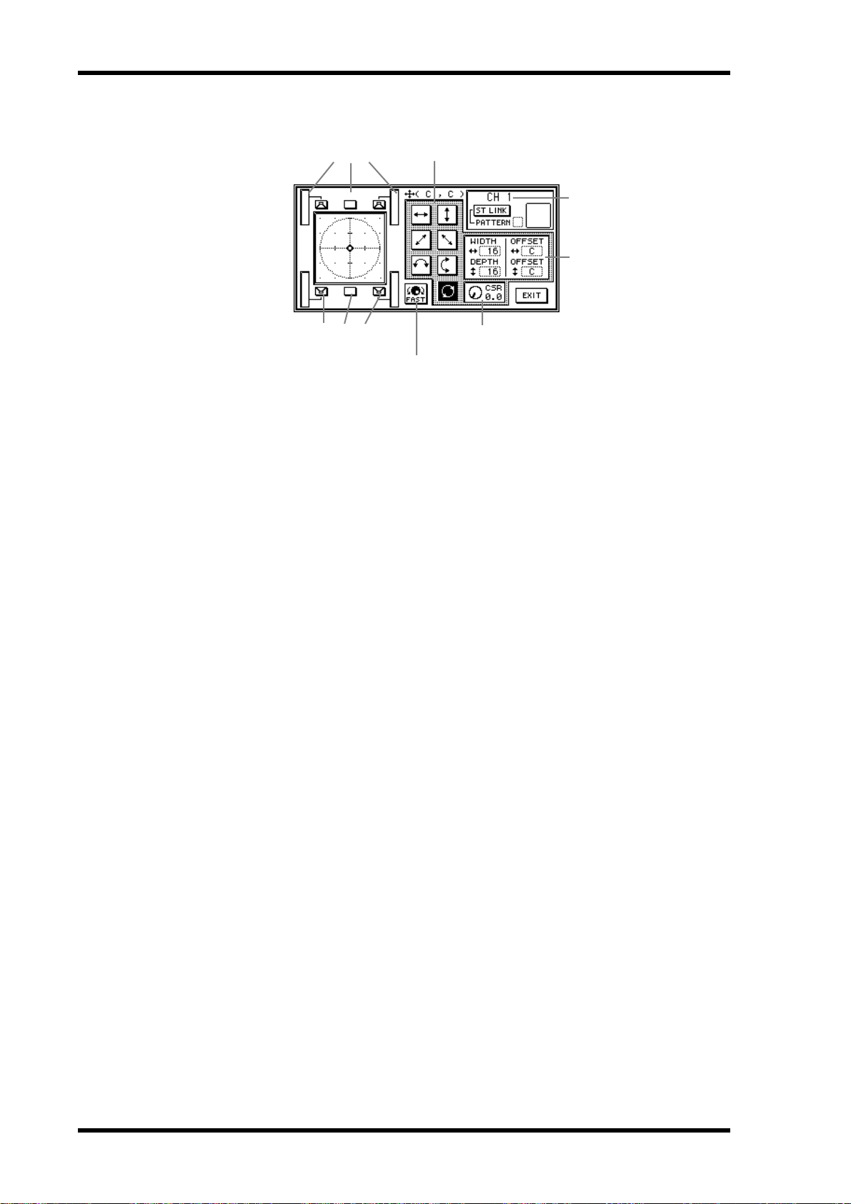
66 Chapter 6—Pan, Routing & Surround Pan
The surround pan trajectory window shown below appears.
Level meters
Surround mode/jump
Trajectories
Selected channel
Width, Depth, Offset
CSR (Center-Side-Ratio)
PARAMETER
wheel speed
3. Use the cursor buttons to select a trajectory, and then press the [ENTER]
button to activate it.
See Surround Pan Trajectories on page 67 for more information.
If you are using a mouse, simply click the trajectory switches.
4. Use the cursor buttons to select the width, depth, and offset parameters
and the PARAMETER wheel to set them.
If you are using a mouse, position the mouse cursor ov er the width, depth, and offset
parameters, press and hold the left mouse button, and then drag the mouse.
The width, depth, and offset parameters are not available for the left-to-right and
front-to-rear trajectories.
5. Move the cursor onto a trajectory switch, and then use the PARAMETER
wheel to pan the sound along the selected trajectory.
When the cursor is on a width, depth, or offset paramet er, the PARAMETER wheel
adjusts that parameter. When the cursor is on a trajectory switch, however, the
PARAMETER wheel can be used to pan the sound along the selected trajectory.
If you are using a mouse, you can mo ve sounds around the two-dimensional pan graph
in real time.
6. Use the cursor buttons to select the surround mode/jump switches, and
then press the [ENTER] button to move sounds.
The surround mode/jump switches correspond to the speaker la yout of the selected
surround pan mode.
7. To close the surround pan trajectory window, use the cursor buttons to
select the EXIT switch, and then press the [ENTER] button.
If you are using a mouse, simply click the EXIT switch.
When the Surr. 1–16 or Surr. 17–24 surr ound pan page appears, you can still use the
PARAMETER wheel to pan the sound along the selected trajectory.
03D—Owner’s Manual
Page 77

Surround Pan Trajectories
The following surround pan trajectories are available.
Left to right—The sound moves from left to right. The follo wing illustrations
show some typical left to right trajectories.
Front to rear—The sound moves from front t o back. The following illustra-
tions show some typical front to rear trajectories.
Using Surround Pan 67
Rear left to front right diagonal—The sound moves on a diagonal trajec-
tory from the rear left to the front right. Width, depth and offset can be set for
this trajectory. The follo wing illustrations show some typical trajectories.
Front left to rear right diagonal—The sound moves on a diagonal trajec-
tory from the front left to the rear right. Width, depth and offset can be set for
this trajectory. The follo wing illustrations show some typical trajectories.
03D—Owner’s Manual
Page 78

68 Chapter 6—Pan, Routing & Surround Pan
Left to right semicircle—The sound moves from left t o right on a semicircle
trajectory. U se the width and depth parameters to set the size and shape of the
semicircle. The shape can be adjusted fr om a semicir cle t o a narrow oval. Use
the offset parameters to offset the trajectory to the left, right, front, or rear . The
following illustrations show some typical trajectories.
Front to rear semicircle—The sound moves from fr ont to rear on a semicir -
cle trajectory. Use the width and depth parameters to set the size and shape of
the semicircle. The shape can be adjusted fr om a semicir cle t o a narrow oval.
Use the offset parameters to offset the trajectory to the left, right, front, or rear.
The following illustrations show some typical trajectories.
Circle—The sound moves on a circular trajectory. Use the width and depth
parameters to set the size and shape. The shape can be adjusted fr om a perfect
circle to a narrow oval. Use the offset parameters to offset the trajectory to the
left, right, front, or rear. The following illustrations show some typical trajectories.
03D—Owner’s Manual
Page 79

Using Surround Pan 69
Stereo Link
For input channels configured as a st er eo pair you can select a pattern and trajectory
and move both signals simultaneously.
1. Configure two input channels as a stereo pair.
See Stereo Pairs on page 114 for mor e information.
2. Use the cursor buttons to select the ST LINK switch, and
then press the [ENTER] button to turn on the Stereo Link
function.
3. Use the cursor buttons to select the PA TTERN parameter and the PARAMETER wheel to select a pattern.
The following illustration shows how the two channels are panned in each patt ern for
each of the available trajectories.
Trajectory
Pattern
CSR (Center:Side Ratio)
For the 3+1 and 3+2+1 surround modes that use a center speak er, the CSR (Center:Side
Ratio) control can be used to set the amount of front-center sound heard thr ough the
center and left and right front speakers.
CSR Description
0
The front-center sound appears only in the left and right speakers.
0.5
1.0
The front-center sound appears in the center and left and right speakers at the
same level.
The front-center sound appears only in the center speaker.
03D—Owner’s Manual
Page 80

70 Chapter 6—Pan, Routing & Surround Pan
03D—Owner’s Manual
Page 81

Solo, Monitors & Meters 71
Solo, Monitors & Meters
7
In this chapter...
About Monitor & Solo . . . . . . . . . . . . . . . . . . . . . . . . . . . . . . . . . . . . . . . . . . . . . 72
Monitor Outputs . . . . . . . . . . . . . . . . . . . . . . . . . . . . . . . . . . . . . . . . . . . . . . . . . 73
Phones . . . . . . . . . . . . . . . . . . . . . . . . . . . . . . . . . . . . . . . . . . . . . . . . . . . . . . . . . . 73
Monitoring . . . . . . . . . . . . . . . . . . . . . . . . . . . . . . . . . . . . . . . . . . . . . . . . . . . . . . 74
Setting Up Solo . . . . . . . . . . . . . . . . . . . . . . . . . . . . . . . . . . . . . . . . . . . . . . . . . . . 75
Using Solo . . . . . . . . . . . . . . . . . . . . . . . . . . . . . . . . . . . . . . . . . . . . . . . . . . . . . . . 76
Solo Safe . . . . . . . . . . . . . . . . . . . . . . . . . . . . . . . . . . . . . . . . . . . . . . . . . . . . . . . . . 77
Two-track Input . . . . . . . . . . . . . . . . . . . . . . . . . . . . . . . . . . . . . . . . . . . . . . . . . . 77
Solo Block Diagram . . . . . . . . . . . . . . . . . . . . . . . . . . . . . . . . . . . . . . . . . . . . . . . 78
Metering . . . . . . . . . . . . . . . . . . . . . . . . . . . . . . . . . . . . . . . . . . . . . . . . . . . . . . . . . 79
Monitor Block Diagram . . . . . . . . . . . . . . . . . . . . . . . . . . . . . . . . . . . . . . . . . . . . 82
03D—Owner’s Manual
Page 82

72 Chapter 7—Solo, Monitors & Meters
About Monitor & Solo
The 03D’ s fle xible monit oring and solo functions are designed for use in a wide range
of applications. Pre-fader or post-fader signals from all inputs and outputs can be monitored via the monitor out and headphones. Solo in Place and M ixdo wn Solo mode,
which work in conjunction with the stereo output, are also provided. Monitor and solo
functions are divided between two pages: Mo ni.Setup and Solo Setup. When the Solo
function is off (i.e., [SOLO] button off), sources selected on the Moni.Setup page ar e
output continuously.
Moni.Setup
On the Moni.Setup page you can select the ster eo output, aux sends, bus outs, or stereo
cascade input as the monitor source. These signals are monit or ed via the monitor out
and headphones. Moni.Setup page functions do not affect the [SOL O] button or ster eo
output. U sing the SEL MODEs you can monitor these signals individually or mixed
together . Signals can be sourc ed pre-fader (PFL) or post-fader (AFL). The Moni.Setup
page also provides a trim control and mono/stereo switch. See Monitoring on page 74
for more information.
Solo
On the Solo Setup page you can set up the solo functions that allow you to monit or
input channels, the stereo input c hannel, effects returns, and ST cascade input. Three
solo modes are available on this page: Recording Solo, M ixdo wn Solo , and Solo in
Place. These modes are used in c onjunction with the [SOLO] and [ON] buttons, which
are used to select channels. Using the SEL MODEs you can monitor these signals individually or mixed together . Signals can be sourc ed pre-fader (PFL) or post-fader (AFL).
The Solo Setup page also provides a trim control and mono/stereo switch. The Solo
Setup page is used only to set up the solo functions. You do not need to select it in order
to use the solo functions. See Setting U p Solo on page 75 for more information. See also
Solo Safe on page 77.
03D—Owner’s Manual
Page 83
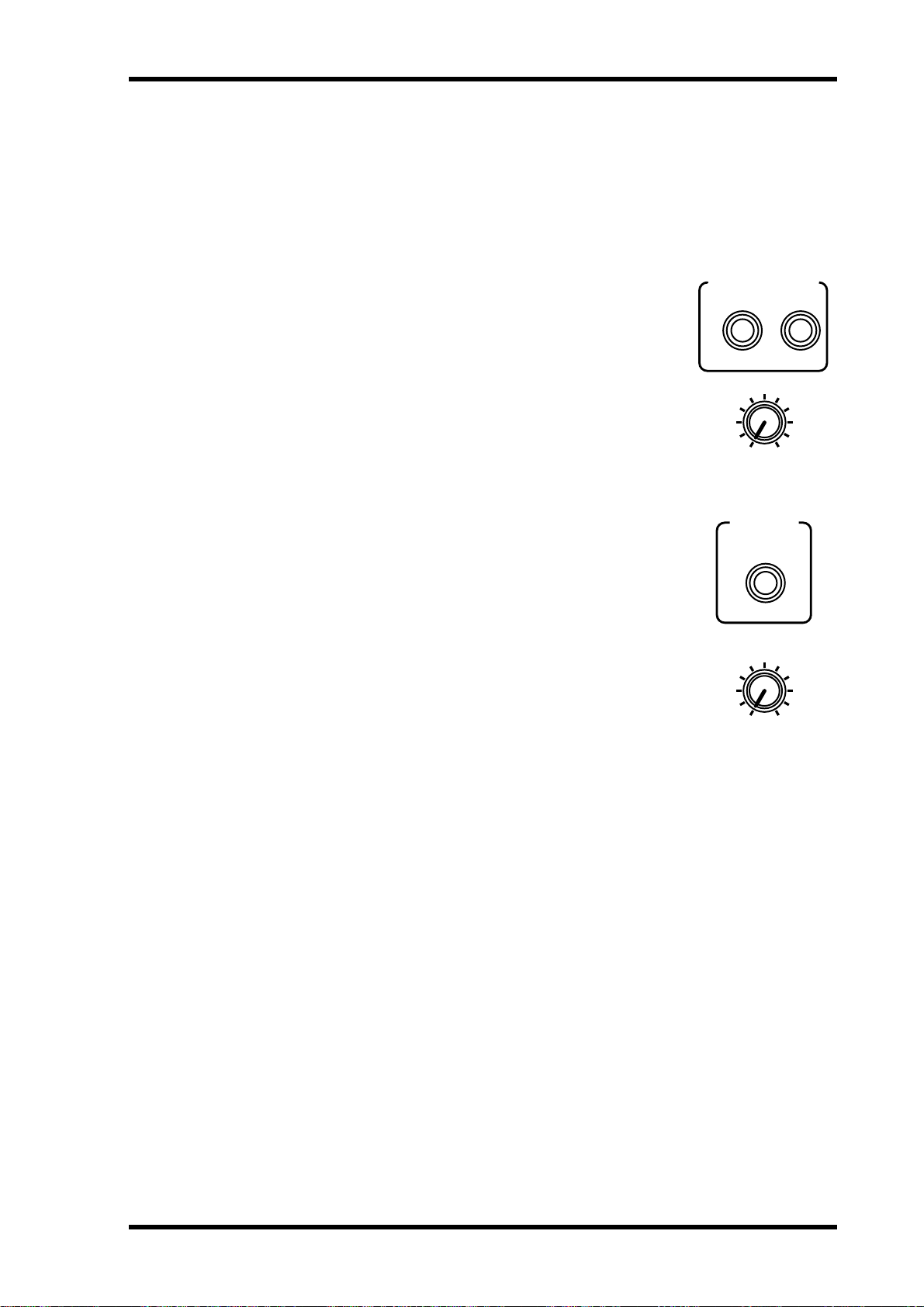
Monitor Outputs 73
Monitor Outputs
Monitor and solo signals are output via the monitor out and phones connections. Mixdown Solo and Solo in Place modes also work with the stereo outputs.
The MONITOR OUT SOL O/2TR IN switch selects the signal sourc e for the monit or
out and phones, and should be set to SOL O for monit oring. See Two-track Input on
page 77 for more information.
Monitor signals are converted to analog using 20-bit 8-times
oversampling D/A con verters, and then output via balanced
1/4-inch phone jacks with a +4 dB nominal output level.
The MONITOR OUT LEVEL contr ol is used t o adjust the level
of the monitor out signal.
Phones
A pair of stereo headphones can be connected to the PHONES
stereo (TRS) phone jack. The phones signal is the same as the
monitor out signal.
The PHONES LEVEL control is used to adjust the lev el of the
phones signal.
MONITOR OUT
+4dB
RL
(BAL)
100
LEVEL
PHONES
100
LEVEL
03D—Owner’s Manual
Page 84

74 Chapter 7—Solo, Monitors & Meters
Monitoring
On the Moni.Setup page you can select the ster eo output, aux sends, bus outs, or stereo
cascade input as the monitor source. These signals are monit or ed via the monitor out
and phones. Functions on this page do not affect the [SOLO] button or stereo output.
1. Use the [SOLO SETUP] button to locate the Moni.Setup page shown
below.
2. Use the cursor buttons to select the parameters, and the [ENTER] button
and PARAMETER wheel to set them.
If you are using a mouse, simply click the switches and drag the rotary control.
MONITOR SOURCE SELECT—These switches are used t o select the signal source for
the monitor out and phones. You can select the stereo out, aux sends, bus outs, and the
stereo cascade input. When aux sends or bus outs are configured as stereo pairs, these
switches are linked.
LISTEN—These switches set the monitor signal source to pre-fader (PFL) or post-fader
(AFL). This is a global setting that affects all monitor sources (i.e., stereo out, aux sends,
etc).
SEL MODE—These switches set the monitor select mode. In LAST MONI mode, only
one monitor source can be selected at a time. In MIX MONI mode, how ev er, several
monitor sources can be selected. Selected signals are mixed.
MONI TRIM—This control is used to adjust the level of the monitor signal from
–60 dB to +6 dB. This contr ol can be adjusted using the P ARAMETER wheel regardless
of cursor position.
STEREO/MONO—This switch sets the monitor and phone’s signals to mono or ste-
reo. It functions independently of the MONO switch on the Solo Setup page. W hen on,
the left and right signals are summed together to form a mono mix. The level of the
summed mix is attenuated –3 dB.
03D—Owner’s Manual
Page 85

Setting Up Solo 75
Setting Up Solo
The Solo Setup page is used to set up the solo functions used to monitor input channels,
the stereo input channel, and effects r eturns. Three solo modes are a vailable: Rec ording
Solo, M ixdo wn Solo, and Solo in Place. These modes are used in conjunction with the
[SOLO] and [ON] buttons, which are used to select channels. The Solo Setup page is
used only to set up the solo functions. You do not need to select it in order to use the
solo functions.
1. Use the [SOLO SETUP] button to locate the Solo Setup page shown
below.
2. Use the cursor buttons to select the parameters, and the [ENTER] button
and PARAMETER wheel to set them.
If you are using a mouse, simply click the switches and drag the rotary control.
STATUS—These switches are used to select the following solo modes: Recording Solo ,
Mixdown Solo, or Solo I n Place.
Status Description
Recording Solo
Mixdown Solo
Solo in Place
(this mode is
essentially a
combination of
the Recording
and Mixdown
Solo modes)
• Soloed channel signals are sent to the Solo bus and then output to the
monitor out and phones.
• This allows you to monitor channels that are not routed to a bus.
• The Stereo bus signal is fed to the Solo bus and then output to the
monitor out and phones (the stereo output, monitor out, and phones all
output the same signal).
• Only channels that are soloed are turned on. All other channels are
muted. Solo safe channels remain as they were before solo mode was
engaged.
• Channels that were turned off before the [SOLO] button was pressed
are turned on when soloed. This means that so long as they are routed to
the Stereo bus they can be monitored.
• Soloed channel signals are sent to the Solo bus and then output to the
monitor out and phones.
• This allows you to monitor channels that are not routed to a bus (same
as for Recording Solo mode).
• Soloed channels that are turned on are output as usual to destinations
other than the monitors, just like when they are not soloed. Channels
that are not soloed, however, are muted. Solo safe channels remain as
they were before solo mode was engaged. This means that even channels that are not routed to a bus can be monitored (this is different to
Mixdown Solo mode).
When 03Ds are cascaded together using YGDAI CD8-CS cascade cards, the status settings can be made only on the cascade master (IN setting), not the cascade slav e (OUT
setting).
LISTEN—These switches set the monitor signal source to pre-fader (PFL) or post-fader
(AFL). This is a global setting that affects all input channels, the st er eo input c hannel,
03D—Owner’s Manual
Page 86

76 Chapter 7—Solo, Monitors & Meters
and effects returns. The third switch, FADER GROUP AFL, w orks with fader groups.
When you solo a channel that is in a fader group , all other channels in that fader group
are also soloed. See Fader Groups on page 112. These switches are not active in MIXDOWN SOLO mode, because the monitor out and phones signals are sourced fr om the
Stereo bus.
Channel On/Off Pair Fader Group
PFL
AFL
Fader Group
AFL
SEL MODE—These switches set the monitor select mode. In LAST SOL O mode, only
one monitor source can be selected at a time. In MIX SOLO mode, however, several
monitor sources can be selected. Selected signals are mixed.
On
Pre-fader signal
Off No Mono No
On Post-fader signal
Off Pre-fader signal
On Post-fader signal Yes
Off Off No No Only soloed channel
Yes Stereo Yes
Yes
Stereo Yes Only soloed channel
No
Yes Stereo
No Mono
Stereo
Only soloed channel
No Only soloed channel
All channels in the same
Yes
group as the soloed
channel
SOLO TRIM—This control is used to adjust the level of the solo signal from –60 dB to
+6 dB. This control is not activ e in MIXDOWN SOL O mode, because the monitor out
and phones signals are sourced from the Stereo bus. This c ontrol can be adjusted using
the PARAMETER wheel regardless of cursor position.
STEREO/MONO—This switch sets the monitor and phone’s signals to mono or ste-
reo. I t functions independently of the MONO switch on the Moni.Setup page. When
on, the left and right channels of the stereo signal are summed together to form a mono
mix. The level of the summed mix is attenuated –3 dB.
Using Solo
1. Make sure the MONITOR OUT SOLO/2TR IN switch is set to SOLO.
2. Set the MONITOR OUT LEVEL control midway.
If you are using headphones, set the PHONES LEVEL control midway.
3. Set up the solo functions on the Solo Setup page. See Setting Up Solo
on page 75 for more information.
4. Press the [SOLO] button.
The SOLO indicator on the display and the [SOLO] and [ON] button indicators flash.
The [ON] buttons now function as solo select buttons, not channel on/off buttons.
The stereo output, aux send, and bus out [ON] butt ons do not flash. To monitor these
outputs, use the Moni.Setup page. See Monitoring on page 74 for more information.
5. Use the [ON] buttons to solo channels.
03D—Owner’s Manual
Exact operation depends on the Solo Setup settings. See Setting Up Solo on page 75 for
more information.
The last channel soloed becomes the currently selected channel, and that channel’ s
[SEL] button lights up. So with the View page selected y ou can instantly see the settings
of the soloed channel without having to select it using the [SEL] button. Channels configured as stereo pairs are selected t ogether.
Page 87

Solo Safe 77
Solo Safe
The Solo Safe function is used to protect channels from being mu t ed when the MIXDOWN SOLO or SOLO IN PLACE mode is used. A safe channel is not muted when
other channels are soloed. The input channels, stereo input channel, effects returns,
and stereo cascade input can be set as safe channels. Solo safe settings ar e made on the
Solo Setup page.
1. Use the [SOLO SETUP] button to locate the Solo Setup page shown
below.
2. Use the cursor buttons to select the SOLO SAFE CHANNEL switches, and
the [ENTER] button to set them.
If you are using a mouse, simply click the SOL O SAFE CHANNEL switches.
Input channels configured as ster eo pairs cannot be set indi vidually.
A channel is set as safe when its SOLO SAFE CHANNEL switch is highlighted.
Two-track Input
The 03D two-track input can be used for confidence monitoring
while recording a stereo mix t o a master machine. W hen the MONITOR OUT SOL O/2TR IN switch is set to SOLO , solo signals are fed
to the monitor out and phones connections. When it is set to 2TR
IN, howev er, the signal connected to the 2TR IN jacks is output. The
levels of the two-track signal being monitored can be set using the
MONITOR OUT and PHONES LEVEL c ontr ols.
The 2TR INs are phono jacks with a –10 dBV nominal input level.
MONITOR
OUT
SOLO/ 2TR IN
2TR IN
R
–10dBV
(UNBAL)
L
03D—Owner’s Manual
Page 88

78 Chapter 7—Solo, Monitors & Meters
Solo Block Diagram
DIGITAL
STEREO
OUT
not changed
4Band
SOLO
ST
1 2 3 4 1 2 L R L R
BUS AUX EFF
1 2 3 4
ON
ST OUT
not changed
ON
not changed
PEQ
4Band
PEQ
ON
BUS OUT
not changed
ON
not changed
PEQ
4Band
PAN
AUX OUT
not changed
ON
not changed
PEQ
4Band
ON
MONITOR
OUT
not changed
MONO
TRIM
SOLO
PHONES
MONITOR
OUT
not changed
MONO
TRIM
SOLO
PHONES
MONITOR
OUT
not changed
MONO
TRIM
SOLO
PHONES
LISTEN
PAN
not changed
ON
not changed
LISTEN
not changed
ON
not changed
not changed
LISTEN
not changed
not changed
not changednot changed
ON
LISTENON
PAN
not changed
ON
Control other CH ON buttons (CH1–16, ST IN, EFF 1/2) except SOLO SAFE CHANNELs.
not changed
ON
not changed not changed
PAN
not changed
ON
not changed
not changed
ON
not changed
Control other CH ON buttons (CH1–16, ST IN, EFF 1/2) except SOLO SAFE CHANNELs.
1-16
17-24
CH INPUT
When solo is off you can monitor the ST OUT, BUS OUT, AUX OUT, and ST CASCADE IN.
In Solo mode, you can monitor CH 1-24, ST IN, and EFF1/2 but cannot monitor ST OUT, BUS OUT, AUX OUT, or ST CASCADE IN.
In Solo mode, the MONO switch on the Moni.Setup page is independent of the MONO switch on the Solo Setup page.
RECORDING SOLO
ST IN
DIGITAL
STEREO IN
1,2
EFFECT
INTERNAL
1-16
CH INPUT
MIXDOWN SOLO
03D—Owner’s Manual
17-24
ST IN
1,2
EFFECT
INTERNAL
1-16
ST IN
17-24
CH INPUT
SOLO IN PLACE
1,2
EFFECT
INTERNAL
Page 89

Metering 79
Metering
Level meters for the 24 input channels, stereo input channel, aux sends, bus outs, effects
returns, YGDAI outputs, and Solo bus are provided on the three Meter pages. The signal source points for input and output meters can be set on Pr e/Post page. Meters can
be used to meter signal levels or the amount of gain reductions being applied by the
dynamics processors. Stereo out levels are metered using the dedicated L STEREO R
LED meters. A switchable peak hold function can be set globally for all meters.
Meter page level meters range from –48 dB t o 0 dB, with CLIP. The CLIP indicators
light up when signals actually clip. So if a CLIP indicator lights up, back off the level a
little. Otherwise, signal distortion may occur.
1. Use the [FADER] button to select the Meter pages.
The CH 1–16 page, which is shown below , contains level met ers for input channels 1 to
16, the stereo input channel, and effects returns 1 and 2. The decibel value below each
meter indicates the position of the corresponding channel fader . The position of the stereo out fader appears in the ST OUT LEVEL box.
2. Use the cursor buttons to select a MODE switch, and then press the
[ENTER] button to activate that mode.
If you are using a mouse, simply click a MODE switch.
MODE—Level meters can be used as input levels meters or gain reduction met e rs. In
INPUT LEVEL mode, meters function as typical level meters. I n GAIN REDUCTION
mode, the meters show the amount of gain reduction being applied by the dynamics
processors. Gain r eduction meters are also a vailable on the Dyn. Edit page. See Dynamics Processors on page 143 for more information.
The MODE switches also appear on the CH 17–24 meter page.
On the following display page, the meter mode is set t o gain r eduction and the noise
gate patched into channel 5 is shown as being closed.
03D—Owner’s Manual
Page 90

80 Chapter 7—Solo, Monitors & Meters
3. Use the cursor buttons to select the PEAK HOLD switch, and then press
the [ENTER] button to activate the peak hold function.
If you are using a mouse, simply click the PEAK HOLD switch.
PEAK HOLD—This switch is used to turn on and off the Peak Hold function for the
Meter pages and the L STEREO R meters. W hen Peak Hold is ON, the meter segments
lit by the loudest signal peaks remain on, pro viding an easy way to check for peak levels.
To turn these meter segments off, set the PEAK HOLD switch to OFF. When the met er
mode is changed, the Peak Hold function is reset. Peak Hold for the Solo and stereo
meters is not affected.
The PEAK HOLD switch also appears on the CH 17–24, and YGDAI meter pages.
The following CH 17–24 meter page contains level meters for input channels 17 t o 24,
the aux sends, and the bus outs. The st er eo input c hannel and effects r eturns 1 and 2
meters also appear on this page. The decibel value below eac h meter indicates the position of the corresponding channel fader. The position of the stereo out fader appears in
the ST OUT LEVEL box.
The following YGDAI Out meter page contains level meters for the eight YGDAI outputs and Solo bus. The boxes below the YGDAI output meters show which signals are
assigned to the YGDAI outputs. See Assigning Signals to the YGDAI Outputs on page
224 for more information. When the mete r mode is set t o GAIN REDUCTION, peak
hold for the XGD AI output met ers is reset when the CH 1–16 or CH 17–24 meter page
is selected.
03D—Owner’s Manual
Page 91
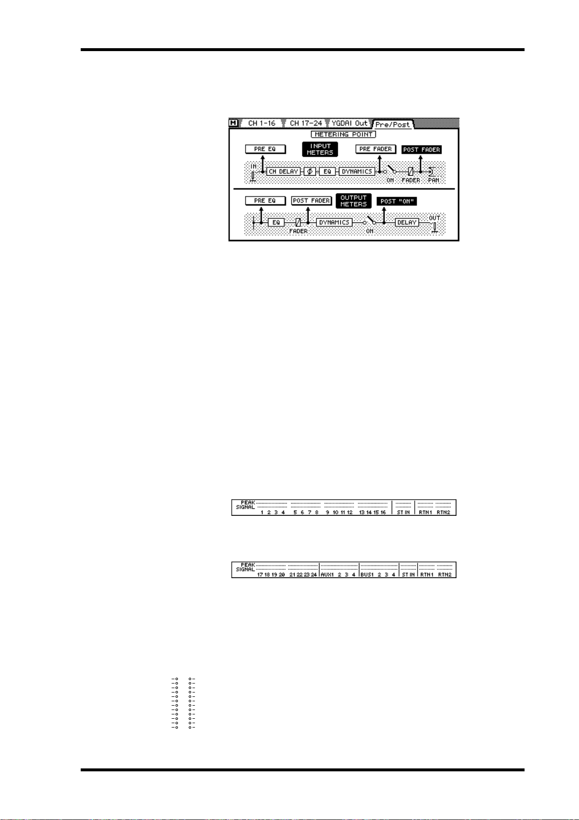
Metering 81
The following Pre/P ost meter page is used to select the signal source points for the input
and output meters. The P eak Hold function is reset whenev er you select another source
point.
4.
Use the cursor buttons to select a meter point switch, and then press the
[ENTER] button to activate it.
If you are using a mouse, simply click the meter point switches.
INPUT METERS—The meter source point for the 24 input channels, st er eo input
channel, and effects returns can be set as PRE EQ, PRE FADER, or POST FADER.
OUTPUT METERS—The meter source point for the aux sends, and bus outs can be set
as PRE EQ, POST FADER, or POST ON.
Signal & Peak Indicators
Signal and peak indicators for all inputs and outputs are available at the top of the display. These indicators are always available and are not affected b y the display pages.
There are two sets of signal and peak indicators. One for input channels 1 to 16, the stereo input channel, and effects returns. The other for input channels 17 to 24, the aux
sends, and the bus outs. The st ereo input channel and effects r eturns indicators appear
in both sets. These sets are switched automatically when the mixing layer is changed.
When the 1–16 Mixing Lay er is selected, peak and signal indicators for input channels
1 to 16, the stereo input c hannel, and effects returns appear, as shown below.
When the 17–24/MASTER Mixing Lay er is select ed, peak and signal indicators for
input channels 17 to 24, the aux sends, and the bus outs appear.
The SIGNAL indicators light up when a signal level of –24 dB is detected, and are
intended to show that a signal is present.
The PEAK indicators light up when the signal level reaches –3 dB.
Main Stereo Meters
L STEREO R
Stereo output signals are metered using the dedicated 12-segment LED
CLIP
–3
–6
bar-type meters next to the display. The meters range from –48 dB to 0 dB.
–9
–12
–15
The CLIP LED lights when the signal actually clips. If a CLIP LED does light,
–18
–24
lower the ST OUT level using the ST OUT fader to prevent signal distortion.
–30
–36
–42
–48
The PEAK HOLD ON/OFF switch on the Meter pages also sets the peak hold
function for the L STEREO R meters.
03D—Owner’s Manual
Page 92

82 Chapter 7—Solo, Monitors & Meters
Monitor Block Diagram
AUX
BUS
1 2 3 4
1 2 3 4
EFF
1 2
ST
L R
SOLO
L R
2TR IN
Meter
MONI
TRIM
L
R
MONO
DA
DA
SOLO/
2TR IN
LEVEL
LEVEL
L
MONITOR
OUT
R
PHONES
03D—Owner’s Manual
Page 93

Stereo Output 83
Stereo Output
8
In this chapter...
About the Stereo Output . . . . . . . . . . . . . . . . . . . . . . . . . . . . . . . . . . . . . . . . . . . 84
Analog Stereo Outputs . . . . . . . . . . . . . . . . . . . . . . . . . . . . . . . . . . . . . . . . . . . . . 84
DIGITAL STEREO OUT . . . . . . . . . . . . . . . . . . . . . . . . . . . . . . . . . . . . . . . . . . . 84
Stereo Output & the YGDAI Interface . . . . . . . . . . . . . . . . . . . . . . . . . . . . . . . . 84
Rec Out & the Stereo Output . . . . . . . . . . . . . . . . . . . . . . . . . . . . . . . . . . . . . . . 84
Monitoring the Stereo Output . . . . . . . . . . . . . . . . . . . . . . . . . . . . . . . . . . . . . . 84
Metering the Stereo Output . . . . . . . . . . . . . . . . . . . . . . . . . . . . . . . . . . . . . . . . . 84
Routing Signals to the Stereo Output . . . . . . . . . . . . . . . . . . . . . . . . . . . . . . . . . 84
Setting the Stereo Output Level . . . . . . . . . . . . . . . . . . . . . . . . . . . . . . . . . . . . . 85
Muting the Ster eo Output . . . . . . . . . . . . . . . . . . . . . . . . . . . . . . . . . . . . . . . . . . 85
Balancing the Stereo Output . . . . . . . . . . . . . . . . . . . . . . . . . . . . . . . . . . . . . . . . 85
Applying EQ to the Stereo Output . . . . . . . . . . . . . . . . . . . . . . . . . . . . . . . . . . . 85
Stereo Output Dynamics Proc essor . . . . . . . . . . . . . . . . . . . . . . . . . . . . . . . . . . 85
Stereo Output Delay . . . . . . . . . . . . . . . . . . . . . . . . . . . . . . . . . . . . . . . . . . . . . . . 86
Stereo Output Block Diagram . . . . . . . . . . . . . . . . . . . . . . . . . . . . . . . . . . . . . . . 87
03D—Owner’s Manual
Page 94

84 Chapter 8—Stereo Output
REC OUT
RL
SOURCE
SELECT
ST OUT
BUS OUT
1-L•2-R
–10dBV
(UNBAL)
About the Stereo Output
The stereo output signal can be output to analog XLR -type connectors, analog REC
OUT connectors, YGDAI digital outputs, or AES/EBU and CO A XIAL digital outputs.
The stereo output features four-band parametric EQ and a dynamics proc essor.
Analog Stereo Outputs
The stereo output signal is conv erted to analog using
20-bit 8-times oversampling D/A con verters, and then
ST OUT
+4dB(BAL)
RL
output via balanced XLR-3-32-type connectors with a
+4 dB nominal output level.
1
2
3
DIGITAL STEREO OUT
The stereo output signal can also be output digitally via the DIGIT AL STEREO OUT
connectors. Two connectors ar e available: one for AES/EBU format and one for COA XIAL format. See Digital Stereo Out on page 219 for more information.
Stereo Output & the YGDAI Interface
In addition to the analog stereo outputs and DIGITAL STEREO OUTs, stereo signals
can be output via the YGDAI digital outputs. See YGDAI Car ds on page 223 for mor e
information.
Rec Out & the Stereo Output
The stereo output signal can be sent to the REC OUT
connectors. These ar e phono jacks with a –10 dB V nominal output level. The REC OUT connect ors can also be
used to output signals from bus outs 1 and 2. The REC
OUT SOURCE SELECT switch is used to select the signal
source.
1
2
3
03D—Owner’s Manual
Solo & the Stereo Output
The Solo in Place and Mixdown Solo modes work in conjunction with the stereo output. See Setting Up Solo on page 75 for mor e information.
Monitoring the Stereo Output
See Solo, Monitors & Meters on page 71 for mor e information.
Metering the Stereo Output
Stereo output signal levels are metered using the 12-segment LED meters. See Metering
on page 79 for more information.
Routing Signals to the Stereo Output
Input channel, ster eo input channel, and effects return signals can be routed to the stereo output. See Stereo Pan, Balance & Routing on page 59 for more information.
Page 95

Setting the Stereo Output Level 85
Setting the Stereo Output Level
6
0
5
10
20
40
60
00
affected by the Mixing Layer, and always works as level co ntrol for the ster eo
output.
Muting the Stereo Output
The stereo output level is controlled using the ST OUT fader . This fader is not
The stereo output can be muted using the ST OUT [ON] button. This butt on
contains an indicator that lights up when stereo output is on. The ST OUT
ON
[ON] button is not affected by the Mixing Lay er setting or [SOLO] function.
Balancing the Stereo Output
The left and right channels of the stereo output signal can be balanced suing the ST
OUT balance control on the page shown below.
1. Use the [PAN/ROUTING] button to locate the page shown below.
2. Use the cursor buttons to select the ST OUT BAL control and the PARAMETER wheel to adjust it.
If you are using a mouse, position the mouse cursor ov er the balance control, press and
hold the left mouse button, and then drag the mouse.
Applying EQ to the Stereo Output
The stereo output features stereo four-band parametric EQ. See EQ on page 45 for
more information.
Stereo Output Dynamics Processor
The stereo output features a stereo dynamics processor . See Dynamics Processors on
page 143 for more information.
03D—Owner’s Manual
Page 96

86 Chapter 8—Stereo Output
Stereo Output Delay
The left and right signals of the analog stereo output can be delay ed indi vidually. This
can be used to compensate for delays in multi-speaker sound reinforcement systems.
1. Use the [DELAY/∅] button to locate the CH Delay page.
2. Press the ST OUT [SEL] button.
The CH Delay page shown below appears.
3. Use the cursor buttons to select the delay parameters and the [ENTER]
button and PARAMETER wheel to set them.
If you are using a mouse, simply click the switches and drag the rotary controls.
ON/OFF—These switches are used to turn on and off the delays. When the cursor is
located within the P ARAMETER window , the [ENTER] button can be used t o turn on
and off the delays without having to select the ON/OFF switch.
PARAMETER—These c ontrols are used t o set the delay time. Dela y can be specified in
either seconds or samples. The maximum dela y is 2,000 samples. The actual delay in
seconds depends on the sampling rate: 45.4 milliseconds at a sampling rate of 44.1 kHz,
and 41.7 milliseconds at a sampling rate of 48 kHz.
Viewing Stereo Output Delay Settings
Stereo output delay settings can be viewed on the following page.
1. Use the [DELAY/∅] button to locate this page.
2. Use the ST OUT [SEL] button to select the stereo output channels and
03D—Owner’s Manual
This page shows the delay time set for the left and right channels of the stereo output.
The delay time cannot be changed on this page. Dela ys can, howev er , be turned on and
off.
the [ENTER] button to turn the delays on and off.
If you are using a mouse, simply click the switches. The switc hes can also be selected
using the cursor buttons.
Page 97

BUS
1 2 3 4
Stereo Output Block Diagram
ST
SOLO
EFF
AUX
1 2 3 4
1 2
L R
L R
MeterMeter
Stereo Output Block Diagram 87
COAXIAL
DITHER
DIGITAL
STEREO
OUT
AES/EBU
STEREO
OUT
4Band
PEQ
4Band
PEQ
Dynamics
BALANCE
ON
DELAY
DELAYDynamics
DA
DA
from BUS OUT 1, 2
SOURCE
SELECT
L
ST OUT
R
L
REC OUT
R
03D—Owner’s Manual
Page 98

88 Chapter 8—Stereo Output
03D—Owner’s Manual
Page 99

Aux Sends 89
Aux Sends
9
In this chapter...
About Aux Sends . . . . . . . . . . . . . . . . . . . . . . . . . . . . . . . . . . . . . . . . . . . . . . . . . . 90
Analog Aux Send Outputs . . . . . . . . . . . . . . . . . . . . . . . . . . . . . . . . . . . . . . . . . . 90
Aux Sends & the YGDAI I nt erfac e . . . . . . . . . . . . . . . . . . . . . . . . . . . . . . . . . . . 90
Monitoring Aux Sends . . . . . . . . . . . . . . . . . . . . . . . . . . . . . . . . . . . . . . . . . . . . . 90
Metering Aux Sends . . . . . . . . . . . . . . . . . . . . . . . . . . . . . . . . . . . . . . . . . . . . . . . 90
Sending Channel Signals to A ux Sends . . . . . . . . . . . . . . . . . . . . . . . . . . . . . . . 91
Pre-fader/Post-fader A ux Sends . . . . . . . . . . . . . . . . . . . . . . . . . . . . . . . . . . . . . 92
Setting A ux Send Master Levels . . . . . . . . . . . . . . . . . . . . . . . . . . . . . . . . . . . . . . 93
Muting Aux Sends . . . . . . . . . . . . . . . . . . . . . . . . . . . . . . . . . . . . . . . . . . . . . . . . . 93
Applying EQ to Aux Sends . . . . . . . . . . . . . . . . . . . . . . . . . . . . . . . . . . . . . . . . . 93
Aux Send Dynamics P r oc essors . . . . . . . . . . . . . . . . . . . . . . . . . . . . . . . . . . . . . 93
Aux Send Ster eo Pairs . . . . . . . . . . . . . . . . . . . . . . . . . . . . . . . . . . . . . . . . . . . . . . 94
Aux Send Block Diagram . . . . . . . . . . . . . . . . . . . . . . . . . . . . . . . . . . . . . . . . . . . 95
03D—Owner’s Manual
Page 100

90 Chapter 9—Aux Sends
About Aux Sends
The 03D features four aux sends. Input channel, stereo input channel, and effects
return signals can be fed to the four aux sends. Each aux send features four -band parametric EQ and a dynamics processor . Aux sends can be used individually or in stereo
pairs. Aux send signals are output via analog phone jacks. They can also be output via
the YGDAI digital outputs.
The 03D does not have dedicated aux return inputs. Use the input channels or ster eo
input channel to return aux signals.
The onboard effects are explained in their own chapter. See Onboard Effects on page
117 for more information.
Analog Aux Send Outputs
Aux send signals are converted to analog using
18-bit D/A converters, and then output via balanced 1/4-inch phone jacks with a +4 dB nominal
output level.
43
AUX OUT
+4dB
(BAL)
Aux Sends & the YGDAI Interface
In addition to the analog aux send outputs, aux send signals can be output via the
YGDAI digital outputs. See YGDAI Cards on page 223 for mor e information.
Monitoring Aux Sends
See Solo, Monitors & Meters on page 71 for mor e information.
Metering Aux Sends
Aux send signal levels can be metered on the Meter pages. See Metering on page 79 for
more information.
21
03D—Owner’s Manual
 Loading...