

Aleen VME Office Service Manual

VME Office
Installation and Programming
Manual
Version 1 Release 1.2 December 2002 Proprietary

2002 Aleen Technologies.
All rights reserved.
The information disclosed herein is proprietary to Aleen Technologies and may not be sold,
transferred or copied without the written consent of Aleen Technologies.
The information contained in this document is subject to change without notice.
VME Office Installation and Programming Manual, Version 1

Publication History
Date Version Release
07/2002 1 1.2
12/2002 1 1.2.2
VME Office Installation and Programming Manual, Version 1

This page is intentionally blank.
VME Office Installation and Programming Manual, Version 1

Contents
Safety........................................................................................................................ IX
1 Introduction ................................................................................................... 1-1
1.1 Manual Audience and Contents....................................................................................... 1-1
1.2 Manual Conventions ........................................................................................................ 1-1
1.3 System Description .......................................................................................................... 1-2
1.3.1 Functional Description ........................................................................................ 1-2
1.3.2 Physical Description ........................................................................................... 1-9
1.3.3 Technical Data.................................................................................................. 1-10
1.4 Workflow ........................................................................................................................1-12
2 Installation ..................................................................................................... 2-1
2.1 Unpacking ........................................................................................................................ 2-1
2.2 Hardware Installation ....................................................................................................... 2-2
2.2.1 VME Office Installation ....................................................................................... 2-2
2.2.2 Connections, Starting Up and Initial Indications................................................. 2-3
2.2.3 Physical Expansion ............................................................................................ 2-4
2.3 Software Setup ................................................................................................................ 2-4
2.3.1 Installing and Downloading the VUP Software................................................... 2-5
2.3.2 PBX Selection..................................................................................................... 2-6
2.3.3 Configuring the VUP Toolbars............................................................................ 2-7
2.3.4 Setting the Location of the VME Office Files...................................................... 2-8
3 VUP Programming ........................................................................................ 3-1
3.1 Quick Installation Using the Installation Wizard............................................................... 3-1
3.2 System Programming ...................................................................................................... 3-2
3.2.1 Setting the PBX Parameters .............................................................................. 3-2
3.2.2 System Parameters ............................................................................................ 3-6
3.2.3 In-band DTMF Protocol ...................................................................................... 3-9
3.3 Automated Attendant Programming .............................................................................. 3-12
3.3.1 Script Programming .......................................................................................... 3-12
3.3.2 Schedule Programming .................................................................................... 3-16
3.4 Programming the Voice Mail.......................................................................................... 3-19
3.4.1 Handling the List of Mailboxes ......................................................................... 3-20
3.4.2 Setting Message Notifications .......................................................................... 3-24
3.4.3 Setting a Mailbox Group ................................................................................... 3-26
4 Administrator's Operations.......................................................................... 4-1
4.1 Accessing VUP Programming Data................................................................................. 4-1
4.1.1 Setting the VUP – VME Office Communication ................................................. 4-1
4.1.2 Setting a Password............................................................................................. 4-4
4.2 Handling Configuration Data............................................................................................ 4-4
4.2.1 Handling Configuration Files .............................................................................. 4-4
4.2.2 Transferring Complete Backup data to VME Office ........................................... 4-6
VME Office Installation and Programming Manual, Version 1

VI Contents
4.2.3 Transferring Configuration Data between VME Office Units............................. 4-6
4.2.4 Transferring Script Messages between VME Office Units ................................ 4-7
4.2.5 Resetting the VME Office ................................................................................... 4-9
4.3 Monitoring and Problem Solving...................................................................................... 4-9
4.3.1 LCD Messages ................................................................................................... 4-9
4.3.2 Line Monitor ...................................................................................................... 4-10
4.3.3 Using Statistics ................................................................................................. 4-13
4.4 Software Upgrading ....................................................................................................... 4-14
5 End User Operations .................................................................................... 5-1
6 DTMF Programming...................................................................................... 6-1
6.1 DTMF Programming Rules .............................................................................................. 6-1
6.2 Entering and Exiting the Programming Mode.................................................................. 6-1
6.3 Programming Commands................................................................................................ 6-2
7 Programming Forms..................................................................................... 7-1
8 VM System Messages................................................................................... 8-1
VME Office Installation and Programming Manual, Version 1

Contents VII
List of Figures
Figure 1-1: General View .................................................................................................................... 1-2
Figure 1-2: VME Office Connections.................................................................................................... 1-3
Figure 1-3 : Front Panels...................................................................................................................... 1-9
Figure 1-4 : VME Office Workflow ...................................................................................................... 1-13
Figure 2-1: RS-232 Cable Electrical Diagram...................................................................................... 2-1
Figure 2-2: VME Office Wall Installation...............................................................................................2-2
Figure 2-3 : Expanding the VME Office to Eight Ports ......................................................................... 2-4
Figure 2-4: VUP's Main Screen............................................................................................................ 2-5
Figure 2-5: PBX Selection List ............................................................................................................. 2-6
Figure 2-6: Toolbar Configuration Tab .................................................................................................2-7
Figure 2-7: File Location Tab ...............................................................................................................2-8
Figure 3-1: PBX Parameters Dialog..................................................................................................... 3-3
Figure 3-2: Call Transfer Tab ...............................................................................................................3-5
Figure 3-3: CP Tone & Disconnect Tab ............................................................................................... 3-6
Figure 3-4: System Parameters Tab .................................................................................................... 3-6
Figure 3-5: Advanced Parameters Dialog ............................................................................................ 3-7
Figure 3-6: In-band DTMF Protocol Dialog ........................................................................................ 3-10
Figure 3-7: Script Menu Dialog........................................................................................................... 3-12
Figure 3-8: Script Opening Tab .......................................................................................................... 3-14
Figure 3-9: Script Status Tab .............................................................................................................3-15
Figure 3-10: Dial Strings Tab .............................................................................................................3-16
Figure 3-11: Time and Date Dialog ....................................................................................................3-17
Figure 3-12: Automatic Scheduling Dialog......................................................................................... 3-18
Figure 3-13: Holiday Schedules Tab.................................................................................................. 3-19
Figure 3-14: List of Mailboxes ............................................................................................................ 3-20
Figure 3-15: New Mailbox ..................................................................................................................3-22
Figure 3-16: Parameters Tab for List of Mailboxes............................................................................ 3-23
Figure 3-17: Local and External Notification Parameters ..................................................................3-25
Figure 3-18: Groups of Mailboxes Dialog........................................................................................... 3-27
Figure 4-1: Communication Selection ..................................................................................................4-2
Figure 4-2: Modem Contacts................................................................................................................ 4-2
Figure 4-3: New Contact’s Details....................................................................................................... 4-3
Figure 4-4: List of Scripts to be Read................................................................................................... 4-8
Figure 4-5: Line Monitoring Dialog .....................................................................................................4-10
Figure 4-6: Typical Line Monitoring Log File ...................................................................................... 4-11
Figure 4-7: General Statistics Dialog .................................................................................................4-13
Figure 4-8: General Statistics............................................................................................................. 4-14
Figure 4-9: Software Upgrading .........................................................................................................4-14
Figure 5-1: Mailbox Quick Reference................................................................................................... 5-2
VME Office Installation and Programming Manual, Version 1

VIII Contents
List of Tables
Table 1-1: VME Office Connections and Display................................................................................. 1-9
Table 2-1: VME Office Packing List...................................................................................................... 2-1
Table 4-1: VME Office LCD Messages ................................................................................................ 4-9
Table 4-2: Line Monitor Codes and Colors ........................................................................................4-12
Table 6-1: VME Office Programming Cross-reference List.................................................................. 6-2
Table 6-2: PBX Commands for DTMF Programming........................................................................... 6-3
Table 6-3: VME Office System Commands for DTMF Programming ..................................................6-8
Table 6-4: In-band DTMF Commands for DTMF Programming ........................................................6-10
Table 6-5: AA Script Commands for DTMF Programming................................................................. 6-13
Table 6-6: AA Scheduling Commands for DTMF Programming ........................................................ 6-15
Table 6-7: VM Mailbox Commands for DTMF Programming............................................................. 6-18
Table 6-8: VM Notification Commands for DTMF Programming .......................................................6-22
Table 6-9: Administrator's Commands for DTMF Programming........................................................ 6-25
Table 7-1: Basic PBX, AA and VM Parameters Form.......................................................................... 7-2
Table 7-2: Message Notification Form ................................................................................................. 7-4
Table 7-3: Time, Data and Scheduling Form ....................................................................................... 7-5
Table 7-4: In-band DTMF Protocol Parameters Form ......................................................................... 7-6
Table 8-1: VM System Messages ........................................................................................................8-1
VME Office Installation and Programming Manual, Version 1

Safety
Safety Precautions
Observe the following safety precautions at all times.
WARNINGS
Do not connect power to VME Office before placing it in its permanent location.
The unit is powered by a 9 V DC power supply. Remove the power connector
before opening the unit.
Hardware Handling
Observe the following hardware precautions at all times.
CAUTIONS
Remove any obstacles that may preclude connection of cables to the unit's rear
panel or to the viewing of front panel indications.
Only personnel qualified by Local Dealer is authorized to open the VME Office
case and replace components or cards.
VME Office Installation and Programming Manual, Version 1

X Safety
Programming Cautions
Observe the following precautions at all times during programming.
CAUTIONS
Parameters applied when selecting a PBX may differ from the parameters
of the existing PBX. In this case, ask for the assistance of the PBX
manufacturer.
After the system initialization process, all previously recorded messages and
settings will be deleted.
You can assign the same number to a mailbox and to a group of mailboxes. In
this case, the message is sent to the mailbox.
Please notice that the VME Office unit is off-line during information transfer to
or from a VUP PC.
To prevent loss of line monitoring data, rename the log file before restarting line
monitoring.
The backup extension key ought to be different from the retrieval key or the
Operator's mailbox ID.
Before deleting a mailbox, remove any call transferred to the mailbox by the
Automated Attendant scripts.
To prevent a system failure, any programmed script must be recorded with the
Opening Greeting Message.
VME Office Installation and Programming Manual, Version 1

1 Introduction
1.1 Manual Audience and Contents
The VME Office Installation and Programming Manual is intended for
system Installers and Administrators responsible for the installation, setup
and programming of the VME Office .
NOTE
Please read this manual before installation, programming and operation.
The manual contents are as follows:
Chapter Heading Appendix Heading
1 Introduction 6 DTMF Programming
2 Installation 7 Programming Forms
3 VUP Programming 8 VM System Messages
4 Administrator's Operations
5 End User Operations
1.2 Manual Conventions
The manual's typographic and command entry conventions are as follows:
Typeface Usage
Manual
NOTE text
Book titles, new words or terms and words to be
emphasized
Heading and text of a note, caution or warning
Bold Text
VME Office Installation and Programming Manual, Version 1
GUI items: dialogs, menu items, field names, etc.
1-2 Introduction
1.3 System Description
This section contains the following:
A functional description consisting of the VME Office environment,
functions and features
A physical description consisting of the unit's connections and
indications
A technical data summary consisting of the unit's main characteristics
1.3.1 Functional Description
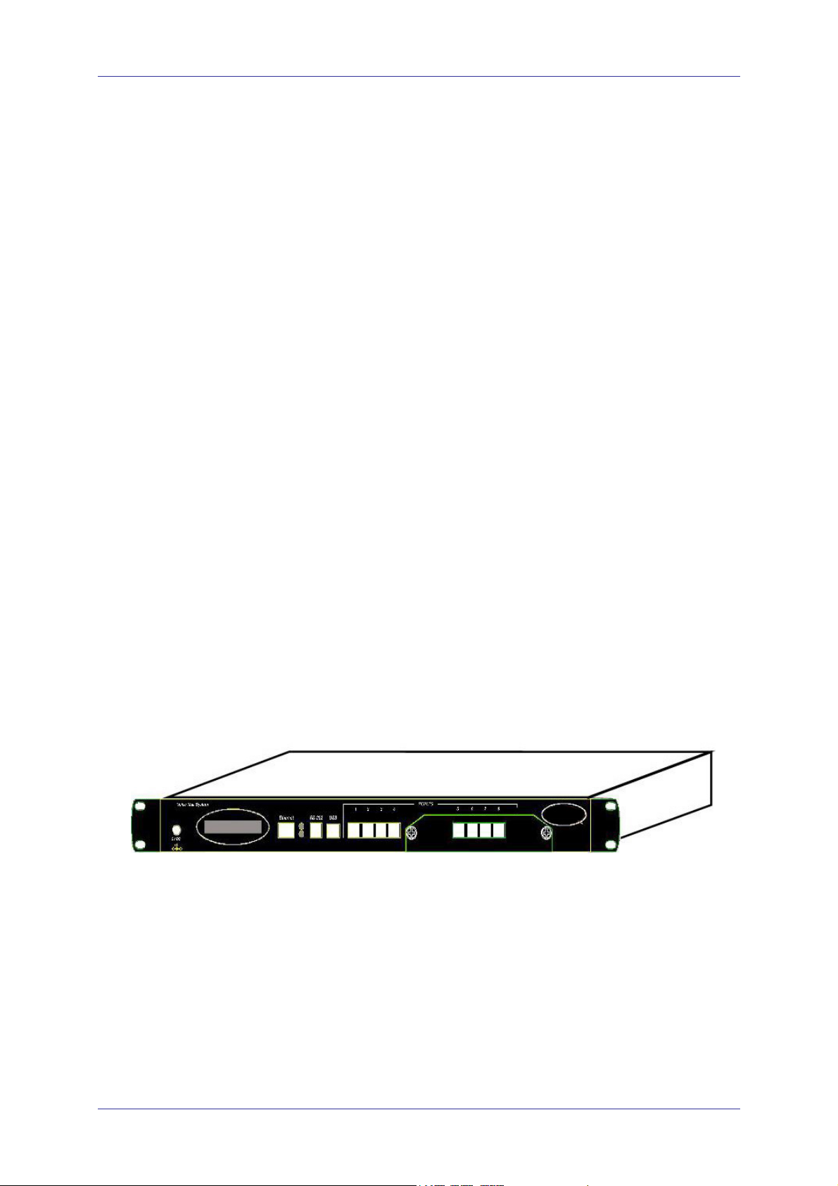
The VME Office shown in Figure 1-1 is a stand-alone multi-lingual
Automated Attendant/VME Office for large to medium sized businesses
with between 50 to 300 employees.
Featuring DSP, Digital Signal Processing, flash memory storage, SMT
production and a real-time clock, the VME Office contains most of the
Automated Attendant (AA), Voice Mail (VM) and administrative features
incorporated in PC-based systems.
The VME Office is available in 4 ports with 18 hours of memory or in 8
ports with 36 hours or memory, provides 500 mailboxes and integrates with
most types of PBX systems via analog ports or by using SMDI protocol.
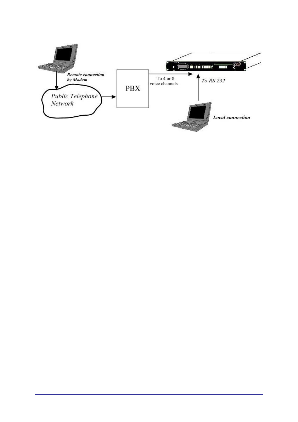
The system operates in the PBX environment, where its 4 or 8 ports are
connected to the voice channel extensions (see Figure 1-2) of the exchange.
It is locally programmed using a direct connection between its RS-232 port
and a PC running the VME Office Voice Mail Utility Program (VUP). It
can also be remotely programmed using the PC modem. DTMF
programming is available using a touch-tone telephone connected to one of
the PBX extensions.
.
Figure 1-1: General View
VME Office Installation and Programming Manual, Version 1
Introduction 1-3
Voice Mail System
Figure 1-2: VME Office Connections
Automated Attendant
The Automated Attendant is a menu-driven program used for transferring
calls to specific departments, extensions and mailboxes. Its main features
are:
Feature Description
Opening
Greeting
Operating
Modes
The VME Office plays a pre-recorded greeting to callers. The
opening greeting usually includes the organization’s name and
instructions on how to reach an extension, department or
Operator, how to switch to different languages, how to leave a
message and how to access a directory.
While the greeting is being played, the callers can access a
department by dialing a single digit, dialing an extension
number or holding on for assistance.
Depending on the time and system schedule, the VME Office
assumes one of four operating modes:
• The day mode for normal business hours, when the VME
Office answers calls with a pre-recorded day greeting
prompting the caller to reach a desired extension, mailbox,
department or directory, or to switch to a different
language.
• The night mode for after working hours, when the VME
Office answers calls with a pre-recorded night greeting that
enables the caller to leave a message in a desired mailbox
,retrieve messages , send a fax etc..
• The holiday mode calls are answered with a special
greeting prompting the caller to leave a message in a
specific mailbox or in the Operator’s mailbox.
• The break mode enables the Administrator to program a
special greeting for breaks during the day.
System
VME Office Installation and Programming Manual, Version 1
If your organizations operating hours vary from day to day, the

1-4 Introduction
Feature Description
Schedules
(Auto-mode)
Administrator can define the daily operating schedules on a
weekly basis, including day, night and break time hours. When
the auto-mode is activated, the VME Office automatically
switches between the day, night and break modes according to
a pre-defined schedule.
The Operator can override the pre-defined schedule and switch
manually to the day, night, break, or holiday mode using a
password.
The VME Office switches automatically to holiday mode on
dates programmed as holidays. During holidays, the VME
Office answers calls with the special holiday greeting.
Fax Detection
Directory
Listing (Dial
By Name)
Call Transfer
Multi-lingual
Option
If the VME Office detects a fax tone (CNG) during the
opening greeting, it automatically transfers the call to the predefined fax (one out of four) extension. There are up to four
fax extensions available in the VME Office.
The VME Office enables the caller to locate a mailbox owner
by dialing the first few letters of the desired parties first or last
name. This feature is programmed by the mailbox owner.
The Administrator can program the VME Office to detect the
Call Progress tone and DTMF signals sent by the PBX.
Subsequently, the call is transferred to an extension in one of
the following modes:
• Non-Supervised − the VME Office transfers the call
immediately without verifying the status of the extension.
• Supervised − the VME Office checks for a Busy or No
Answer signal before transferring the call to the extension.
• Semi-Supervised − the VME Office only checks for a
Busy signal before transferring the call to an extension.
The VME Office allows up to 3 languages per unit. Callers can
choose the preferred language from the Automated Attendant
during the opening-greeting menu. The Administrator can
select the mailbox menu language for each mailbox owner.
Answering on
the First Ring
To avoid delays, the Administrator can configure each VME
Office individual port to answer incoming calls on the first
ring.
Script Menus
The VME Office supports up to 98 script menus. A script
menu is a recorded announcement that can accept a digit entry
(0 to 9) while being played. Based on the digit entered, the
VME Office can perform one of the following actions:
• Transfer the call to another script menu
• Transfer the call to another script menu and change the
language
• Transfer the call to an extension or hunt group
• Transfer the call to a mailbox or a mailbox group
• Transfer the call to a specified Operator
VME Office Installation and Programming Manual, Version 1

Introduction 1-5
Feature Description
• Dial a DTMF string
• Retrieve messages from a mailbox
• Disconnect the line
• Leave a message
• Play the directory listing
Transfer Call
to Operator
Dial a String
Greeting by
Port
Up to eight extensions can be defined as Operators and a call
can be transferred from the Script Menu or from the Personal
Greeting message to a specified Operator.
The VME Office can be programmed to dial any predefined
DTMF string while the script opening greeting message is
being played. Dial a string can perform any internal PBX
feature, i.e. during the company greeting the external
subscriber is instructed to press 7 to be able to connect to
another external subscriber. Dial a String will convert the digit
7 to hook flash plus the external line access code plus the
subscriber number and then Voice Mail will hang up.
The VME Office can be programmed to play an Opening
Greeting Message when detecting an incoming call on the
specified port.
Voice Mail
The Voice Mail program receives and delivers messages using mailbox ID
numbers and mailbox owners' passwords. Messages can be saved, deleted or
transferred to other mailboxes. The VM main features are:
Feature Description
Real/Virtual
Mailboxes
Personalized
Mailboxes
Message
Waiting
Notification
Mailbox
Features
The VME Office supports up to 500 real and virtual mailboxes.
A real mailbox is connected to an extension, whereas a virtual
mailbox is not.
Mailbox owners can personalize their mailboxes by recording
a personal greeting, assigning a personal password to the
mailbox and setting optional parameters.
The VME Office informs a mailbox owner about recorded
messages by means of a local lamp, local ring notification or
external notification to an external phone number. Notification
to pagers is also supported.
• Personal Greeting – mailbox owners can record or change
personal greetings at all times from any touch-tone
telephone. First, callers hear the personal greeting of the
called extension. Then they can leave a message or transfer
the call to an Operator or to another extension.
• Date and Time Stamp – the Administrator can program the
VME Office to indicate the start of a message and the date
and time each message was recorded.
• Message Deletion – messages are deleted either manually
by the mailbox owner or automatically after the maximum
VME Office Installation and Programming Manual, Version 1

1-6 Introduction
Feature Description
number of days defined by the Administrator.
• Message Forwarding – the mailbox owners can forward
copies of messages to other mailboxes or mailbox groups.
Mailbox owners can also record an introduction to the
forwarded message.
• Message Reply – mailbox owners can reply to messages
and record messages in the sender’s mailbox.
Mailbox
Groups
Do Not
Disturb Mode
Individual
Language
Selection
Adjustable
Recording
Length
A caller can send a message to all the members of a mailbox
group simultaneously.
All defined mailboxes belong to the All Group mailbox group.
In addition, the Administrator can create up to four mailbox
groups, each containing up to twenty mailboxes. Mailboxes
can belong to more than one group. Mailboxes can be added
or deleted from a mailbox group by the Administrator. A
mailbox group greeting can be assigned to each mailbox group.
Mailbox owners can set their mailboxes in the Do Not Disturb
Mode.
When a caller dials an extension that is in the Do Not Disturb
mode using the Automated Attendant menus, the VME Office
plays a special Do Not Disturb menu and does not transfer the
call to the extension.
The mailbox owner can select one of the languages supported
by the VME Office. When the mailbox owner enters the
mailbox, the VME Office automatically switches to the
selected language.
The Administrator can select the length of all VME Office
recorded messages. The selected length controls the following
types of messages: scripts, greetings, names and received
messages.
Number of
Stored
Messages
Each mailbox can store up to 92 messages. This number can
increase to 99 if eight subsequent messages are recorded in the
same mailbox. The Administrator controls and can change this
parameter for each mailbox. The default setting for this
parameter is 30 (a maximum of 37 subsequent messages can be
stored in the same mailbox). The Administrator can also limit
the number of messages stored in the mailboxes.
System Administration
The VME Office is equipped with many administrative functions intended
to provide the Administrator with flexible tools for fast implementation,
setup and programming, as well as for long-term operations like monitoring
and maintenance. The main administrative features of the VME Office
system are:
Feature Description
Configuration
VME Office Installation and Programming Manual, Version 1
The basic VME Office unit is available with four ports and
eighteen hours of recording time.

Introduction 1-7
Feature Description
The Administrator can increase the number of ports and
recording time by adding a four-port expansion module to the
basic VME Office unit.
Programming
Integration
with Your
PBX
Disconnection
Methods
The Administrator can program the VME Office using:
• A computer running the Voice Mail Utility Program. In this
case, it is highly recommended to save the configuration
files for each installation.
• Via a modem connection.
• Touch-tone telephone using DTMF Codes.
The Administrator can integrate the VME Office with the PBX
using:
• In-band DTMF Protocol. This type of integration is
achieved by setting up the communication protocol of the
PBX and the VME Office unit (answering a call,
transferring a call, recalling as a result of a Busy or No
Answer condition, etc.).
• SMDI Integration via the RS-232 serial port. This type of
integration must be specifically developed for each type of
PBX.
Some PBXs can notify the VME Office through the line
interface when a call is terminated using Loop Disconnect,
DTMF Codes or the Busy and Disconnect Cadence. When the
VME Office detects this situation, the line is disconnected and
the unit is ready to receive another call.
Message
Notification
Security
Passwords
Line Monitor
Modem
Support
LCD
The VME Office automatically notifies the mailbox owner of
new messages. Notification may be local (to a PBX extension)
or remote (to a telephone at a remote location, a cellular
telephone or a pager).
The VME Office supports three types of 4-digit passwords:
• Administrator for accessing all data stored in the VME
Office.
• Operator for accessing the system operating modes: Day,
Night, Holiday and Break.
• Mailbox for accessing individual mailboxes, where the
mailbox owners can change the password at all times.
This option has been enhanced in the VME Office to display
all incoming and outgoing DTMF and system codes through
the RS-232 cable or modem connection.
The VME Office unit is equipped with a built in V.32 bis
modem, operating at 14.4 Kbps with fallback rates of 12, 9.6,
and 4.8 Kbps. As the call is terminated, the VME Office hangs
up in order to clear the port for the next call.
Modem support can be enabled or disabled.
On the front panel of the VME Office the LCD display shows
the status of all 8 ports, system error messages and the current
VME Office Installation and Programming Manual, Version 1

1-8 Introduction
Feature Description
mode of operation.
Reports and
Configuration
Print out
Backup and
Restore
Feature
Software
Upload
Extension
Size
Memory Reorganization
Memory
Alarm
PBX Selection
The VME Office can supply a printout of the statistic and
system configuration reports. The statistic reports contain
general information about usage (memory, ports, mailboxes)
and the configuration reports contain information regarding the
VME Office configuration.
The Voice-mail Utility Program (VUP) creates a backup file,
which includes full system configuration and recordings using
the local RS-232 connection.
The VUP updates the systems software using the local RS-232
connection.
The VME Office supports flexible extension sizes between 2 to
6 digits.
The flash memory is re-organized in a manner similar to the
de-fragmentation process deployed for PCs hard disks. The
VME Office constantly monitors the memory usage and
automatically invokes the memory reorganization.
When 85% of the memory has been used, the VME Office
sends a voice alarm message to the "supervisor mailbox".
The VME Office can be easily configured for operation with
specific PBX’s using the PBX selection option in the VUP.
This option supplies a list of PBXs with default integration
parameters.
Wizard
Import
*.WAV file
An Installation Wizard has been provided in the software for
quick installation and integration of the unit.
Windows media files (*.wav) can be used to create Script
Opening Greeting Messages. A source *.wav file can be
transferred and automatically converted into the required
VME-Office format.
VME Office Installation and Programming Manual, Version 1
Introduction 1-9
1.3.2 Physical Description
The VME Office unit comes in a 422 x 43 x 165 mm metal case suitable for
mounting in a standard 19" communication rack or on a wall.
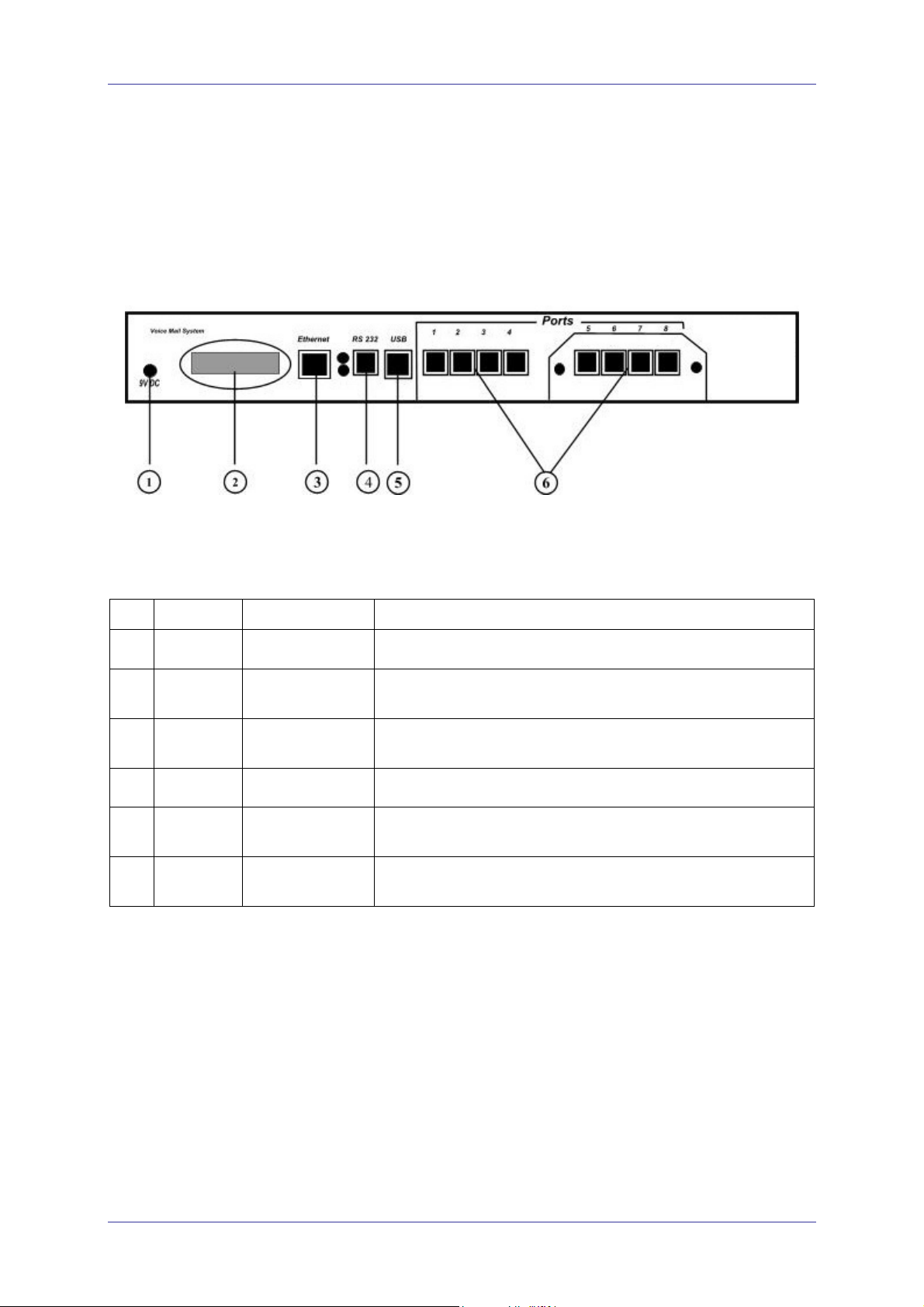
All VME Office connection and display components are located on the
unit's front panel as shown in Figure 1-3. For details regarding the front
panel components, refer to Table 1-1.
Figure 1-3 : Front Panels
Table 1-1: VME Office Connections and Display
No. ID Item Function
1
2
3
4
5
6
9VDC
-
Ethernet
RS-232
USB
Ports
Connector Connects the VME Office to an external power supply.
16x2 character
LCD display
RJ-45 socket Connects the VME Office to the Local Network (not
RJ-11 socket Connects the VME Office to a PBX or PC.
USB socket Connects the VME Office to a PC USB port (not operational
RJ-11 sockets Connects the VME Office to 4 or 8 PBX extensions (the
Displays the operational mode and populated ports of the unit
and a brief message in case of error.
operational in this version).
in this version).
latest option is implemented using a 4-port expansion card).
VME Office Installation and Programming Manual, Version 1

1-10 Introduction
1.3.3 Technical Data
General Data
Number of voice mail ports 4 or 8
Extension size 2 to 6 digits flexible
Recording time 4 ports – 18 hours
8 ports – 36 hours
Mailboxes 500
Messages per mailbox Up to 92 (programmable)
Operator's extensions Up to 8
Fax extensions Up to 4
Script messages Up to 98
DTMF strings Up to 10
In-band DTMF entries Up to 20
Legal extension groups Up to 10
Modem support
Interface V.32 bis
Rates 14.4 Kbps with fallback to 12, 9,6 and 4.8 Kbps
Number of languages Up to 3
Features
Automated Attendant
Opening greeting
Operating modes: day, night, holiday, break
System schedules: daily, weekly, holidays
Fax detection
Directory listing (dial by name)
Call transfer modes: non-supervised, supervised, semi-
supervised
Multi-lingual option
Answering on first ring
Script menus
Transfer call to specific Operator
Transfer call to extension, mailbox, group of mailboxes
Dial a string
Greeting per port
Features
VME Office Installation and Programming Manual, Version 1

Introduction 1-11
Voice Mail
Real/virtual, announcer mailboxes
Personalized mailboxes
Message waiting notification (Local and External)
Personal greeting
Day and time stamp
Message handling: deletion, forwarding, reply ,save
Mailbox groups
Do Not Disturb mode
Adjustable recording length
Quantity of stored messages
Administration
Configuration: 4 or 8 PBX extension ports
Importing *.WAV files for opening greetings
Programming: PC or touch-tone telephone
Integration with PBX: in-band DTMF Protocol or out-
of-band via RS-232 port
Disconnection methods: Loop Disconnect, DTMF
Disconnect, Busy Disconnect and Disconnect tones
Security passwords: Administrator, Operator, mailbox
Line monitor: incoming/outgoing calls via RS-232 port
or modem connection
Modem support: enabled/disabled
LCD: front panel monitoring
Reports: statistics and configuration print-out
Backup and restore: system configuration and
recordings
Software download: via RS-232 port connection
Memory re-organization
Memory Alarm: when 85% in use
PBX selection with default integration parameters
Wizard for first time programming
Characteristics
VME Office Installation and Programming Manual, Version 1

1-12 Introduction
Electrical
DC Power Supply 9VDC/1.5 A
Line Voltage 24 to 72VDC
DC Leakage Current
On-hook Insulation Resistance
between Line Terminal and
Ground
Ring Capacitor
On-hook Impedance
Ring Detect 27 to 100VAC/16 to 60Hz
DC Resistance (off-hook)
Impedance (off-hook)
Imbalance Ratio 300 to 3400Hz, 46dB minimum
Return Loss 300 to 3400Hz > 18dB
Current during Break
DTMF Transmission:
Frequency Tolerance
Frequency Level (High Group)
Frequency Level (Low Group)
10µA maximum
0 to 100VDC, 5MΩ minimum
100 to 200VDC, 30KΩ minimum
500 VAC/50Hz, 20KΩ minimum
100 VAC/25Hz, 100KΩ minimum
0.47µF ± 10%
@ 50VDC, 40 VAC/25Hz, 3000Ω minimum
24 to 66VDC @ 20 to 100mA 100 to 350Ω
300 to 3400Hz 500 to 700Ω
700µA, maximum
+1.5%
-6 to -8dBm
-8 to –10dBm
Inter-digit Pause in Tone
Dialing
Fax CNG Tone Detection 1100Hz ± 38Hz
Mechanical
Dimensions (W x H x D) 422 x 43 x 165 mm
Weight 2.2 Kg
70 to 80ms
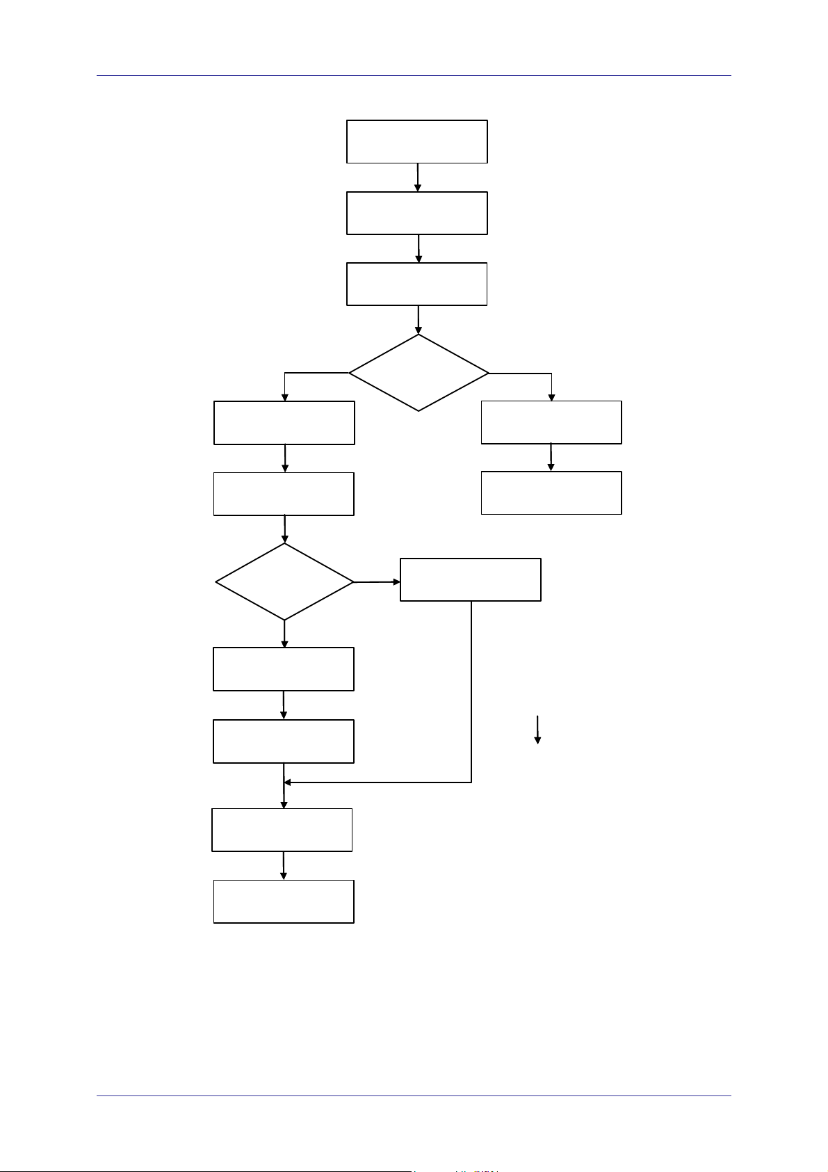
1.4 Workflow
Figure 1-4 provides the workflow for the VME Office setup and
programming operations carried out according to this manual.
VME Office Installation and Programming Manual, Version 1
Introduction 1-13
Chapter 2:
Installation,
Sec. 2.1
Chapter 2:
Installation,
Sec. 2.2.1
Unpacking
Rack/Wall Mounting
Chapter 2:
Installation,
Sec. 2.3.1
Chapter 2:
Installation,
Sec. 2.3.2 to 2.3.4
Chapter 4:
Administrator’s
Sec. 4.2.2 and 4.2.2.5
Operations,
Chapter 2:
Installation,
Sec. 2.2.2
VUP
VUP Installation
and Launching
VUP Setup
First Time
Programming
?
No
Configuration Data Transfer
to PC
Voice Mail System
Connection and Power Up
Programming
Type
?
Yes
Wizard Programming
Touch-tone
Telephone
Telephone - Voice Mail
System Communication
Setup
DTMF Programming
Chapter 3: VUP
Programming,
Sec. 3.1
Chapter 6:
DTMF Programming,
Sec. 6.2
Chapter 6:
DTMF Programming,
Sec. 6.3 (for forms,
see Chapter 6)
Chapter 3: VUP
Programming,
Sec. 3.2 to 3.4
(for forms, see
Chapter 6)
Chapter 4:
Administrator’s
Operations,
Sec. 4.1
Chapter 4:
Administrator’s
Sec. 4.2.2 and 4.2.2.5
Operations,
VUP Programming
Voice Mail System
Communication and
Password Setting
Configuration Data Transfer
to VME-Office
Figure 1-4 : VME Office Workflow
VME Office Installation and Programming Manual, Version 1

1-14 Introduction
This page is intentionally blank.
VME Office Installation and Programming Manual, Version 1
2 Installation
This chapter consists of the following:
Unpacking the VME Office unit and accessories
Installation of the VME Office
Installing and setup of the VUP software
2.1 Unpacking
Check the VME Office shipment according to the packing list in Table 2-1.
Table 2-1: VME Office Packing List
NOTES
No. Item Quantity Note
1 VME - Office Unit 1
2 Rack/wall mounting brackets 2
3 Screws 4
4 Nuts 4
5 Washers 4
6 Power Supply, 9VDC 1
7 CD (installation software and manual) 1
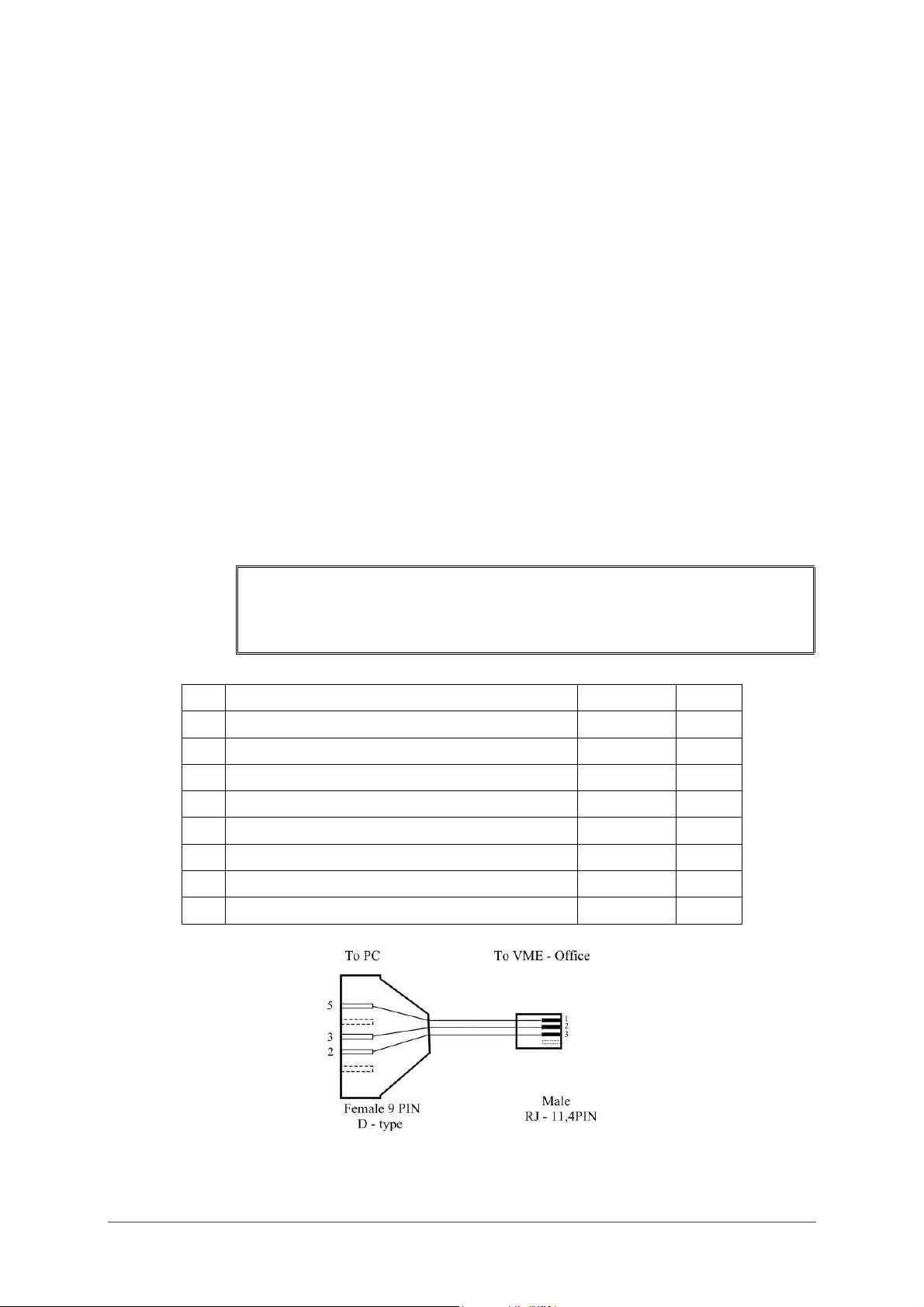
8 RS-232 cable 1 b.
a. Report any damage to the package or to its contents to your local dealer.
b. For the electrical diagram of the RS-232 cable, see Figure 2-1.
Figure 2-1: RS-232 Cable Electrical Diagram
VME Office Installation and Programming Manual, Version 1
2-2 Installation
2.2 Hardware Installation
This section consists of the following:
VME Office installation
Connections, starting up and initial indications
VME Office expansion to eight ports
2.2.1 VME Office Installation
NOTE
VUP programming can be done prior to the hardware installation(see VUP
Programming in Chapter 3). After the programming, proceed with the hardware
installation and connections (see this section) and transfer the configuration and
recording files to the VME Office (see Accessing VUP Programming Data
Chapter 4).
To install the VME Office in a 19" rack:
in
1. Attach a bracket to each side of the VME Office unit adjacent to its
front panel and fasten each bracket with the three screws provided.
2. Place the VME Office unit in the 19" rack and fasten it to the rack rails
using four screws, washers and spring washers.
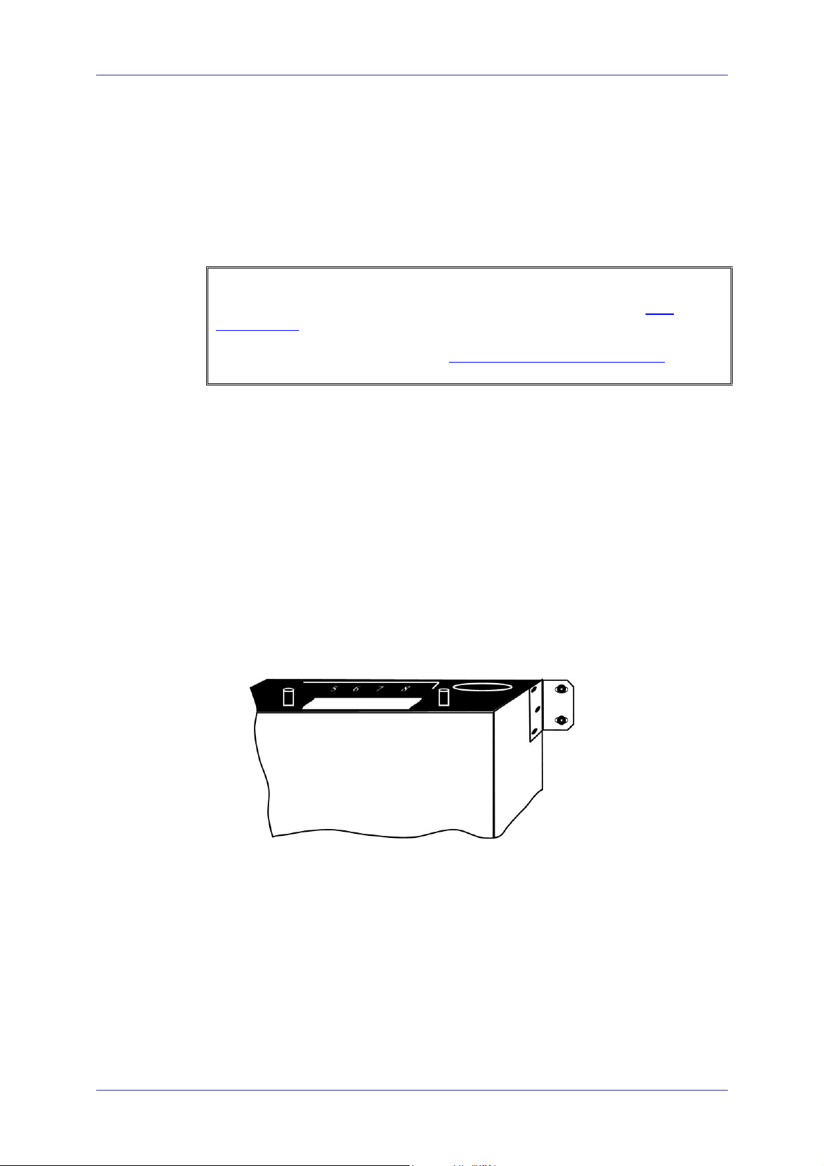
To install the VME Office on a wall:
1. Attach a bracket to each side of the VME Office unit adjacent to its rear
panel (see Figure 2-2, below) and fasten each bracket with the two
screws provided.
Figure 2-2: VME Office Wall Installation
2. Drill four holes in the wall.
3. Fasten the VME Office unit flush with the wall using four screws,
washers and spring washers provided.
VME Office Installation and Programming Manual, Version 1

Installation 2-3
2.2.2 Connections, Starting Up and Initial Indications
1. Connect each extension port on the right side of the VME Office front
panel to an extension line using an RJ-11 cable.
NOTE
Each RJ-11 socket on the front panel of the VME Office supports one analog
telephone line.
CAUTION
In order to prevent damage to the RS-232 driver chip, Do Not connect an analog
telephone line to the RS-232 socket.
2. Plug the 9VDC adapter jack into the power supply connector on the left
side of VME Office front panel.
3. Plug the 9VDC adapter into the main power supply outlet to turn the
VME Office on.
4. Notice the indications on the LCD display. For details, see LCD
Messages in Chapter 4.
5. For local programming of the VME Office, connect an RS-232 cable to
the VME Offices RS-232 socket and to the COM port of the PC
running the VUP program.
Remote programming of the VME Office is done via a modem
connected to the public telephone network, provided that the
Administrator has programmed this option in the VME Office.
NOTES
a. VME Office connections for local and remote programming are schematically
shown in Figure 1-2.
b. A RS-232 cable is provided with the VME Office for local programming.
6. Call each VME Office line from any extension and listen to the default
greeting informing you that the system has not been programmed yet
(see VM System Messages
, System Message No. 000).
VME Office Installation and Programming Manual, Version 1
2-4 Installation
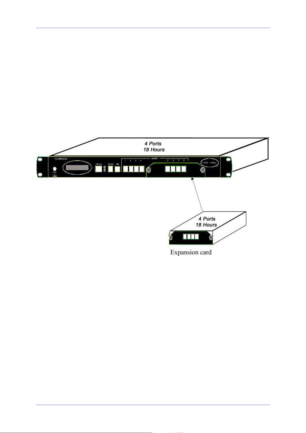
2.2.3 Physical Expansion
To upgrade a VME Office unit from four to eight ports
1. Remove the two screws and take off the cover from the expansion slot
on the right side of the VME Office front panel (see Figure 2-3).
2. Slide the expansion card into the slot and carefully push it in until it fits
into the unit's rear connector.
3. Fasten the expansion card using its two captive screws to the unit's
front panel.
Figure 2-3 : Expanding the VME Office to Eight Ports
2.3 Software Setup
This section consists of the following:
Installing and downloading the VUP software
Selecting a PBX
Configuring the VUP toolbars
Setting the location of the VME Office files
Press the PBX selection button for selecting the relevant PBX for
installation. All the default parameters regarding the selected PBX will
automatically open in the VUP. These parameters are: Transfer Code, Hook
Flash Time, Message Light On and Off codes and In-band DTMF Protocol.
VME Office Installation and Programming Manual, Version 1
Installation 2-5
2.3.1 Installing and Downloading the VUP Software
Install the VUP software on the PC or laptop being used for the set up,
programming and managing of the VME Office unit.
NOTES
a. The VUP software can be installed, downloaded and used for creating the VME
Office configuration and scripts recording without physically connecting the PC
containing the VUP software to the VME Office unit.
b. When the PC containing the VUP software is physically connected to the VME
Office unit, a message indicating that the COM port of the PC has not been
configured will appear when attempting software download. Press OK and
configure the COM port.
c. To establish a connection, follow the relevant procedures: Connections,
Powering Up and Initial Indications in Chapter 2 and Setting the VUP PC –
VME Office Communication in Chapter 4.
To install and download the VUP software
1. Insert the VUP CD in the CD-ROM drive of your PC.
2. The CD should run automatically .If it doesn’t , press Start Run and
browse the CD for the VUP Set up icon.
3. Click the VUP Installation icon and follow the instructions on the
screen.
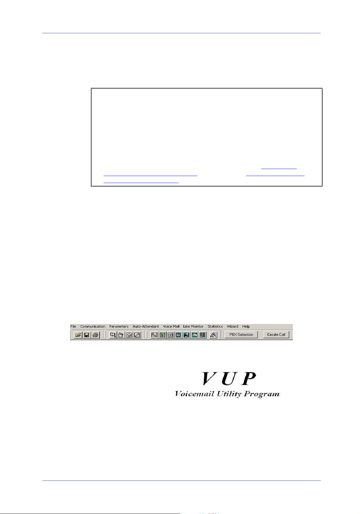
4. To start the VUP program, click Start Programs VUP. The
VUP's main screen appears (see Figure 2-4).
Alternatively, double-click the VUP – VME Office icon on the PC
desktop.
Figure 2-4: VUP's Main Screen
VME Office Installation and Programming Manual, Version 1
2-6 Installation
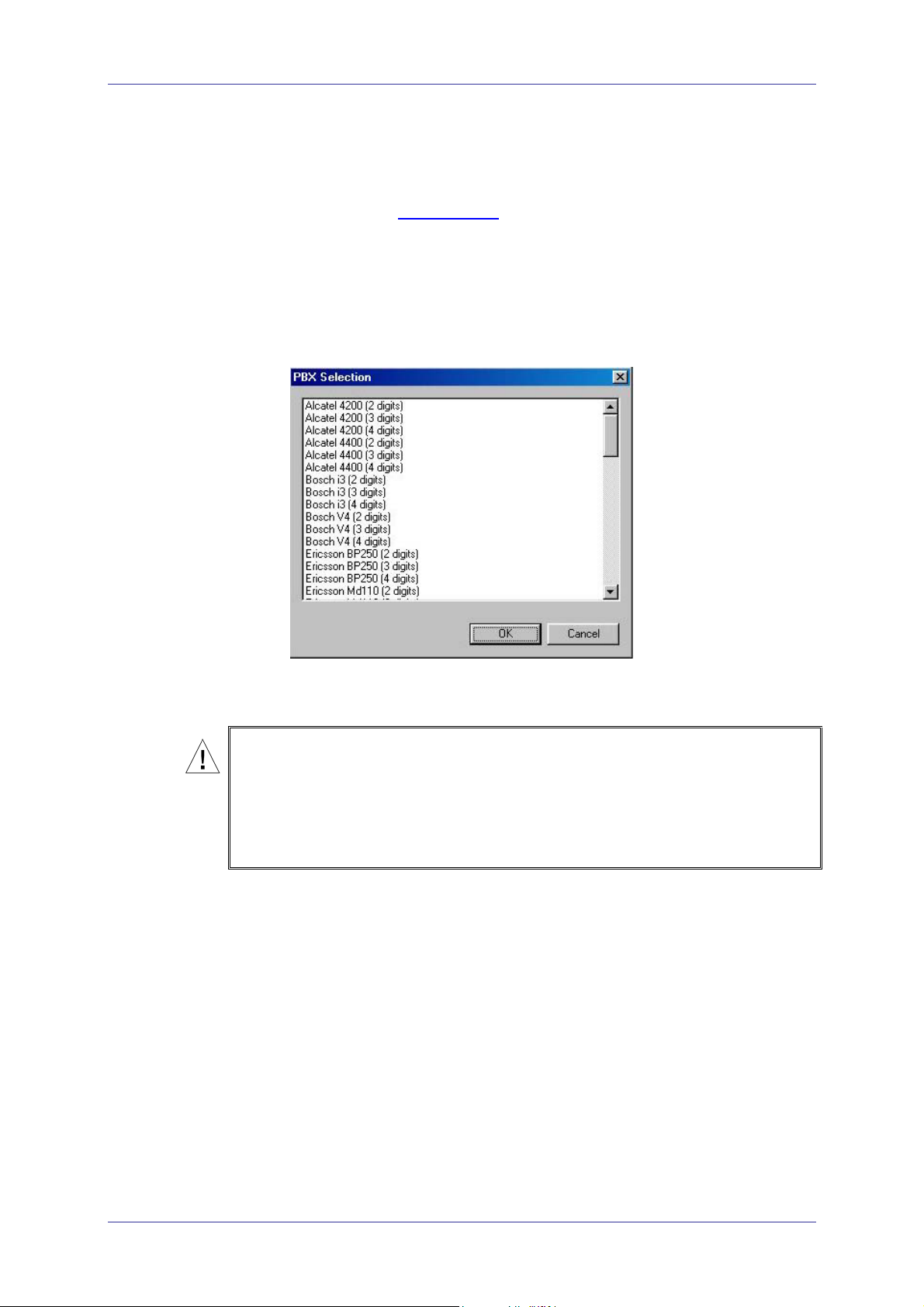
2.3.2 PBX Selection
Selecting a PBX from the PBX Selection list enables quick and easy
integration for the VME Office from a predefined list of PBX’s with default
parameters. Refer to PBX Settings
from those provided in the PBX selection.
To select a PBX
1. Press the PBX Selection button in the VUP's toolbar.
2. From the PBX Selection dialog (see Figure 2-5) select the relevant
PBX and press OK.
in order to change the parameters apart
Figure 2-5: PBX Selection List
CAUTIONS
a. Parameters applied when selecting a PBX may differ from the parameters of
the existing PBX. In this case, request for assistance from the PBX
manufacturer.
b. To obtain a list of the PBX parameters, from the VUP's main menu, select File
Print Settings Menu PBX Parameters.
VME Office Installation and Programming Manual, Version 1
 Loading...