

Aleen Ear-5000 Service Manual


EAR 5000
Installation and Programming Manual
Version 6.0 Release 2.0 June 2002

NOTICE
This publication refers to the EAR 5000 Auto Attendant System, Release 2
Additional copies of this manual may be obtained from Aleen Technologies.
Reproduction of this manual or parts thereof without written permission from Aleen
Technologies is strictly prohibited.
Aleen Technologies reserves the right to modify the hardware and software described
herein without prior notice. However, changes made to the hardware or software
described do not necessarily render this publication invalid.
WARRANTY
In the event that the product proves to be defective in workmanship or materials within a
period of one year from date of shipment, Aleen Technologies shall repair or replace the
same at its discretion. Transportation will be the responsibility of the dealer/distributor.
Under no circumstances shall Aleen Technologies be liable for consequential or
special damages, loss of revenue or user/dealer expenses arising out of or in
connection with the use or performance of the product, whether base on contract,
tort or any other legal agreement.
The following shall void the above warranty: malfunctions resulting from fire, accident,
neglect, abuse or acts of God; use of improper electrical power; or repair of, tampering
with or alteration of the product by anyone other than Aleen Technologies authorized
personnel.

TABLE OF CONTENTS
Table of Contents
1. INTRODUCTION................................................................................................................1-1
1.1 F
1.2 A
2. DESCRIPTION AND INSTALLATION...........................................................................2-1
2.1 T
2.2 P
2.3 I
3. DTMF PROGRAMMING...................................................................................................3-1
EATURES AND SERVICES
1.1.1 System Features .....................................................................................................1-2
1.1.2 Automated Attendant Features...............................................................................1-4
1.1.3 Voice Mail Features...............................................................................................1-6
BOUT THIS MANUAL
HE BASIC SYSTEM
HYSICAL DESCRIPTION
2.2.1 Side Panel ..............................................................................................................2-3
2.2.2 Front Panel............................................................................................................2-4
NSTALLATION
2.3.1 Unpacking..............................................................................................................2-5
2.3.2 Installing the EAR 5000.........................................................................................2-5
2.3.3 Expanding the System.............................................................................................2-8
................................................................................................................2-5
...............................................................................................1-2
.....................................................................................................1-8
........................................................................................................2-2
..................................................................................................2-3
3.1 E
3.2 F
3.3 D
3.4 S
3.5 P
3.6 P
Installation and Programming Manual a
NTER ING AND EXITING THE PROGRAMMING MODE
IRST TIME PROGRAMMING CHECKLIST
EFINING
ETTING THE TIME AND DATE
ROGRAMMING TH E OPERATIONAL MODE
ROGRAMMING TH E
3.6.1 Creating Mailboxes..............................................................................................3-10
3.6.2 Creating Mailbox Groups....................................................................................3-12
3.6.3 Notification...........................................................................................................3-13
PBX P
ARAMETERS
EAR 5000 ....................................................................................3-10
.........................................................................................3-3
........................................................................................3-8
.........................................................................3-2
......................................................................3-8
......................................................3-1

Table of Contents
3.7 P
3.8 A
ROGRAMMING TH E AUTOMATED ATTENDANT SCRIPT MENU
3.7.1 Recording Script Messages..................................................................................3-17
3.7.2 Programming Script Messages ............................................................................3-18
3.7.3 Directory Listing Programming...........................................................................3-25
3.7.4 Reset Script Message Programming to Default...................................................3-26
3.7.5 Supervised, Semi-Supervised and Non-Supervised Transfers..............................3-26
DDITIONAL FEATURES
3.8.1 Changing Passwords............................................................................................3-29
3.8.2 Activate Force Reorganize...................................................................................3-30
3.8.3 Changing to/from Day Light Saving Time............................................................3-31
3.8.4 Changing the Operational Mode..........................................................................3-31
3.8.5 Playing a System Message...................................................................................3-32
3.8.6 Playing All System Messages...............................................................................3-32
3.8.7 System Message Setting........................................................................................3-32
3.8.8 Listening to the Software Version Number...........................................................3-33
3.8.9 Resetting the System.............................................................................................3-33
3.8.10 Adjusting Recording Length.................................................................................3-33
................................................................................................3-29
.....................................3-17
4. PROGRAMMING BY COMPUTER.................................................................................4-1
4.1 C
4.2 S
4.3 I
4.4 S
5. USER OPERATION INSTRUCTIONS.............................................................................5-1
5.1 I
5.2 U
5.3 R
5.4 M
b Installation and Programming Manual
ONNECTING THE
YSTEM REQUIREMENTS
NSTALLING THE
TARTING
NTRODUCTION
SER’S MAIN MENU
ETRIEVE MESSAGE MENU
AILBOX PARAMETERS
5.4.1 Record Greeting.....................................................................................................5-3
5.4.2 Record Name..........................................................................................................5-3
5.4.3 Directory Listing....................................................................................................5-4
EUP...............................................................................................................4-3
EAR 5000 TO T
.................................................................................................4-2
EUP.....................................................................................................4-2
...............................................................................................................5-1
.......................................................................................................5-1
..................................................................................................5-2
HE COMPUTER
............................................................................................5-1
.........................................................4-1

Table of Contents
5.4.4 Change Password...................................................................................................5-4
5.4.5 Do Not Disturb (DND)...........................................................................................5-5
5.4.6 External Notification..............................................................................................5-5
5.4.7 Pager Notification..................................................................................................5-6
5.4.8 Return to Previous Menu........................................................................................5-6
5.5 S
5.6 R
5.7 Q
END MESSAGE
ETURN TO AUTO ATTENDANT
UICK REFERENCE GUIDE
..............................................................................................................5-7
..............................................................................................5-8
......................................................................................5-7
6. PROGRAMMING THE IN-BAND DTMF PROTOCOL................................................6-1
6.1 P
ROGRAMMING TH E
EAR 5000
BY TELEPHONE
.............................................................6-1
6.1.1 Defining an In-Band DTMF Code for an Event.....................................................6-1
6.1.2 Selecting an Operation Type..................................................................................6-3
6.1.3 Selecting a destination ...........................................................................................6-4
6.1.4 Defining the Time to Wait for the First DTMF Character.....................................6-4
6.1.5 Defining the Time to Wait Between DTMF Characters.........................................6-4
6.1.6 MATRA Support.....................................................................................................6-5
6.2 S
AMPLE PROGRAMMING
.................................................................................................6-5
6.2.1 Working with the SIEMENS Hicom 150E Office PBX...........................................6-5
7. TROUBLESHOOTING ......................................................................................................7-1
APPENDIX A PROGRAMMING COMMANDS....................................................................A-1
APPENDIX B PROGRAMMING FORMS.............................................................................. B-1
APPENDIX C SYSTEM MESSAGES......................................................................................C-1
APPENDIX D SPECIFICATIONS ...........................................................................................D-1
Installation and Programming Manual c

1. INTRODUCTION
The EAR 5000 is a small stand alone multilingual Automated Attendant system for
organizations that have between eight and eighty employees. The EAR 5000
incorporates state of the art technology, including DSP, flash memory and SMT
production.
Figure 1-1 General View
The EAR 5000 is available in two or four ports and with up to 8 mailboxes. It
provides a three hours recording time .
The EAR 5000 can be integrated with most types of PBX’s through the analog
ports or through the RS-232 serial port.
The system administrator can be programmed by the computer using the EAR
Utility Program (EUP) or by touch-tone telephone.
Installing the EAR 5000 is quick and easy. Just mount it on a wall next to the PBX
and connect it to the SLT interfaces and to the main power supply with an external
power adapter.
Installation and Programming Manual 1-1

Introduction
The EAR 5000 is ready for use immediately after the system administrator
completes a short procedure that includes setting up integration parameters,
mailboxes, notification type, system schedules and opening greetings. Mailbox
owners can then set up their own personal mailbox parameters.
1.1 Features and Services
The EAR 5000 is a powerful Auto Attendant system at an affordable price. It
contains most of the useful features and services provided by PC-based systems
but at a lower cost. The EAR 5000’s features can be divided into three groups:
• System Administration
• Automated Attendant
• Voice Mail
1.1.1 System Features
• Configuration
The EAR 5000 is available with two ports and three hours of recording time.
The system administrator can upgrade the EAR 5000 by:
− Adding a two port expansion card to the motherboard to provide four ports
• Programming
The system administrator can program the EAR 5000 by:
− Touch-tone telephone using DTMF tones
− Computer using the EAR Utility Program (EUP). The installer should
save the files containing the parameters set in each installation.
• Integration with your PBX
The system administrator can integrate the EAR 5000 with the PBX through:
− In-Band DTMF Protocol integration using DTMF strings. This type of
integration is achieved by setting up the communication parameters on the
PBX and the EAR 5000s, including answering a call, transfer, recall from
busy, recall from no answer, the notification parameters and more.
− Out-band integration through a serial port (RS-232) applying the PBX
parameters to the EAR 5000. This type of integration must be developed
separately for each type of PBX.
1-2 Installation and Programming Manual

Introduction
•••• Loop Current Disconnection
Some PBXs have the capability, which enables them to notify the EAR 5000
through the line interface when a call is terminated. When this situation is
detected by the unit, the line is disconnected and the EAR 5000 is then ready
to receive another call.
• Message Notification
The EAR 5000 automatically notifies the mailbox owner of new messages in
different ways according to the system configuration. Notification may be
local (to a PBX extension) or remote (to a telephone at a remote location, a
cellular telephone or a pager).
• Security Passwords
The EAR 5000 supports three types of passwords, each with four digits:
− System Administrator. Gives access to all data stored in the EAR 5000.
− Operator. Gives access to the operating modes of the system. The
available operating modes are: Day, Night, Holiday and Break.
− Mailbox. Gives access to individual mailboxes. Mailbox owners can
change the password at any time.
• Line Monitor
The EAR 5000 sends all incoming DTMF codes to the EUP, from all the
ports, simultaneously through the RS-232 cable. The line monitor is a
powerful tool to simplify the integration and installation of the EAR 5000
with the PBX.
Installation and Programming Manual 1-3

Introduction
1.1.2 Automated Attendant Features
The EAR 5000’s automated attendant answers incoming calls and through a series
of recorded menus and telephone directories, helps the callers reach the desired
extensions.
• Opening Greeting
The EAR 5000 plays a pre-recorded greeting to callers. The opening greeting
usually includes the organization’s name, how to reach an extension,
department or operator, how to switch languages, how to leave a message and
to access a directory.
During the greeting, callers can access a department by dialing a single digit,
dialing the extension number or holding for assistance.
• Operating Modes
Depending on the time and the system schedule, the EAR 5000 answers
external calls with one of four opening greetings:
− Day Mode
During normal business hours, the EAR 5000 answers calls with a pre-
recorded daytime greeting. The daytime greeting enables the caller to
reach a requested extension, mailbox, department, and directory or to
switch languages.
− Night Mode
During non-working hours, the EAR 5000 answers calls with a pre-
recorded nighttime greeting that enables the caller to leave a message in a
requested mailbox.
− Holiday Mode
During holidays, the EAR 5000 answers calls with a special greeting that
enables the caller to leave a message in a specific mailbox or in the
operator’s mailbox.
− Break Mode
The system administrator can program part of the day mode as break time.
During break time, the EAR 5000 answers calls with a special greeting that
enables the caller to leave a message in a specific m ailbox or in the
operator’s mailbox.
1-4 Installation and Programming Manual

Introduction
•••• System Schedules (Auto-Mode)
If your organization has operating hours that v ary from day to day, the system
administrator can define the daily operating schedules on a weekly basis,
including daytime, nighttime and break time hours. When the Auto m ode is
activated, the EAR 5000 automatically switches between the day, night and
break modes according to the pre- defined schedule.
The operator can override the pre-defined system schedule and switch
manually to day, night, break, or holiday mode using a password.
• Holiday Schedules
The EAR 5000 switches automatically to Holiday mode on dates programmed
as holidays. During holidays the EAR 5000 answers calls with the special
holiday greeting.
• Fax Detection
If the EAR 5000 detects a fax tone (CNG) during the opening greeting, it
automatically transfers the call to the pre-defined fax extension.
• Directory Listing (Dial By Name)
The EAR 5000 can provide a list of mailbox owner names. The directory
listing enables calls to be transferred to all extensions configured within the
list. A caller can access the directory listing by following instructions during
the opening greeting.
In order to enable a directory listing call transfer, the mailbox owner must
record his name and a three-letter code. A caller can reach the proper
extension after dialing the respective code and verifying a correct extension
according to the mailbox owner’s name.
The system administrator enables two methods of directory listing: according
to the mailbox owners first or last name.
• Call Transfer
The system administrator can program the EAR 5000 to detect the Call
Progress tone and DTMF signals sent by the PBX and transfer the calls to
extensions in one of the following modes:
− Non-Supervised. The EAR 5000 transfers the call immediately without
verifying the status of an extension.
− Supervised. The EAR 5000 checks for a busy or answer signal before
transferring the call to an extension.
Installation and Programming Manual 1-5

Introduction
− Semi-Supervised. The EAR 5000 only checks for a busy signal before
transferring the call to an extension.
• Multilingual Option
The EAR 5000 can operate in three languages simultaneously. The system
administrator can configure each mailbox to operate in one of the three
selected languages. The caller can select the language in which the system
messages (prompts) are played.
• Answering on the First Ring
To avoid delays, the system administrator can set up the EAR 5000 on each
individual port to answer incoming calls on the first ring.
• Script Menus
The EAR 5000 supports up to 39 script menus. A script menu is a recorded
announcement that can accept a digit entry (0-9) during playback. Based on the
digit entered, the EAR 5000 can take one of the following actions:
− Transfer the call to another script menu
− Transfer the call to another script menu and change the language
− Transfer the call to an extension or hunt group
− Transfer the call to a mailbox or a mailbox group
− Dial a strings of DTMF
− Retrieve messages from a mailbox
− Disconnect the line
− Leave a message
− Play the directory listing
− Record a call
1.1.3 Voice Mail Features
The EAR 5000 enables a caller to leave a message, recorded in his own voice, in
any mailbox. The mailbox owner can access his/her mailbox at any time from any
touch-tone telephone and listen to his/her messages. Mailbox owners can also
modify their own mailbox parameters.
1-6 Installation and Programming Manual

Introduction
•••• Real/Virtual Mailboxes
The EAR 5000 supports 8 real and virtual mailboxes. A real mailbox has a
telephone extension, whereas a virtual mailbox does not.
• Personalized Mailboxes
Mailbox owners can personalize their mailboxes by recording a personal
greeting, assigning a personal password to the mailbox and setting optional
parameters.
• Personal Greeting
Mailbox owners can record or change personal greetings at any time from any
touch-tone telephone. Callers first hear the personal greeting of the extension
called and then they can leave a message.
• Day and Time Stamp
The system administrator can program the EAR 5000 to indicate the start of
each message and the day and time it was recorded.
• Message Deletion
Mailbox owners can manually delete messages or the system administrator can
program the EAR 5000 to automatically delete all messages after a specified
number of days.
•••• Message Forwarding
Mailbox owners can forward copies of messages to other mailboxes or
mailbox groups. Mailbox owners can also record an introduction to the
forwarded message.
• Message Reply
Mailbox owners can reply, directly, to a message and record a message in the
sender’s mailbox.
• Mailbox Groups
A caller can send a message to all the members of a mailbox group at one time.
All defined mailboxes belong to the “All Group” mailbox group. In addition,
the system administrator can create up to four mailbox groups, each containing
up to twenty mailboxes. Mailboxes can belong to more than one group and can
be added to or deleted from a mailbox group by the system administrator. Each
mailbox group can be assigned with a mailbox group greeting.
Installation and Programming Manual 1-7

Introduction
•••• Do Not Disturb Mode
Mailbox owners can set their mailboxes in the Regular Mode or Do Not
Disturb Mode. When a caller dials a Do Not Disturb extension using the
Automated Attendant menus, the EAR 5000 plays a special “Do Not Disturb”
menu and does not transfer the call to the extension.
•••• Individual Language Selection
The mailbox owner or caller can select one of the languages supported by the
EAR 5000. When the mailbox owner or caller enters the mailbox, the EAR
5000 automatically switches to the selected language.
•••• Adjustable Recording Length
The system administrator can select the length of all recorded messages in the
EAR 5000. The selected length will control the following types of messages:
scripts, greetings, names and incoming messages. Changing this parameter will
affect the operation EAR 5000.
• Automatic Gain Control (AGC)
When this feature is enabled, the EAR 5000 automatically adjusts the line
volume so incoming messages will be recorded at the same level.
1-8 Installation and Programming Manual

Introduction
1.2 About this Manual
This manual presents information needed to install, program and maintain the EAR
5000. It is divided into the following sections:
1. INTRODUCTION
Introduces the EAR 5000 and lists its features.
2. DESCRIPTION AND INSTALLATION
Provides a functional description of the EAR 5000 and installation
instructions.
3. DTMF PROGRAMMING
Describes how to program the EAR 5000 from any DTMF telephone.
4. PROGRAMMING BY COMPUTER
Describes the installation and basic operational concepts of the EAR Utility
Program (EUP).
5. USER OPERATING INSTRUCTIONS
Explains how to program and use a mailbox.
6. PROGRAMMING THE IN-BAND PROTOCOL
Describes how to program the EAR 5000 to detect the In-Band DTMF
protocol sent by the PBX.
7. TROUBLESHOOTING
Presents answers to commonly asked questions on operating the EAR 5000.
APPENDIX A
Summarizes the programming commands.
APPENDIX B
Contains the DTMF programming forms.
APPENDIX C
Lists the system messages.
APPENDIX D
Lists the system specifications.
Installation and Programming Manual 1-9

2. DESCRIPTION AND INSTALLATION
The EAR 5000 is a digital system consisting of a:
• Sophisticated DSP voice-processing device
• Flash memory for storing voice recording and parameter data
• Central Processing EAR 5000
• Two or four ports
• Real-time clock
The EAR 5000 provides two major services:
• Automated Attendant
Uses menus and sub-menus to transfer calls to specific departments,
extensions or mailboxes.
• Voice Mail
Receives and delivers messages. Each mailbox has its own number and
mailbox owners have passwords enabling them access to their mailboxes.
Messages can be saved, deleted or transferred to other mailboxes. Mailbox
owners can also send identical messages to groups of mailboxes or to all the
mailboxes in the system.
By configuring the following, the EAR 5000’s Automated Attendant and Voice
Mail System can be customized to suit the needs of the company:
• PBX parameters
• Automated Attendant script menus and customized “Busy”, “No Answer” and
“Do Not Disturb” menus in up to three different languages simultaneously.
• Voice Mail features include: mailboxes, mailbox groups and various types of
message notifications for each mailbox
Installation and Programming Manual 2-1
Description and Installation
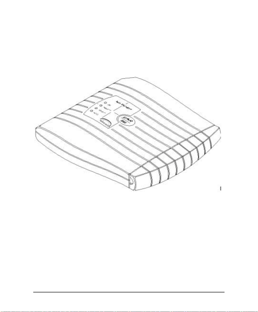
2.1 The Basic System
The EAR 5000 comes with two lines and three hours recording time.
You can upgrade the EAR 5000 by:
• Adding a two line expansion card to the motherboard to provide four lines
Figure 2-1 Options for Upgrading the Basic System
2-2 Installation and Programming Manual
Description and Installation
2.2 Physical Description
The functional components of the EAR 5000 are located under the side panel
cover. The LEDs are on the left side of the front panel. The bottom panel has two
indented holes for wall mounting.
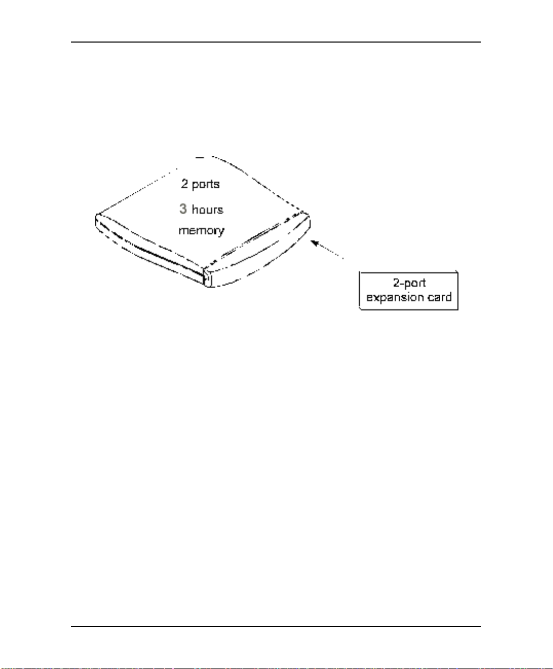
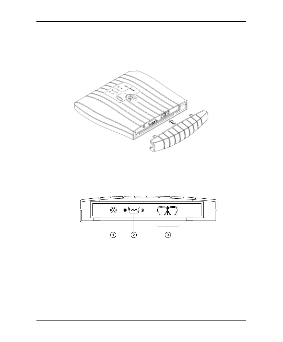
Figure 2-2 General View of the EAR 5000 after Removing the Cover
2.2.1 Side Panel
Figure 2-3 Side Panel
The numbered items in the following description correspond to the labels in
Figure 2-3.
1. Power Supply Connector Connects the EAR 5000 to the external power supply
2. RS-232 Connector Connects the EAR 5000 to the PBX or a PC
3. 2 RJ-11 Sockets Connects the EAR 5000 to 2 or 4 PBX extensions
Installation and Programming Manual 2-3
Description and Installation
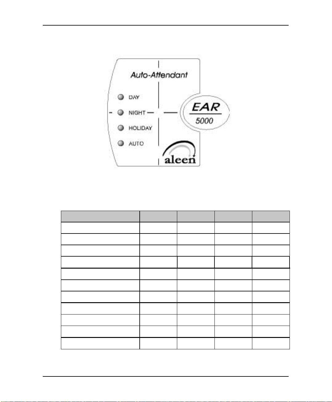
2.2.2 Front Panel
Figure 2-4 LEDs on the Front Panel
The following table describes the function of the four LEDS on the front panel.
STATUS DAY NIGHT HOLIDAY AUTO
Day Mode: Man ual On Off Off Off
Night Mode: Manual Off On Off Off
Holiday Mode: Manual Off Off On Off
Break Mode: Manual On On Off Off
Day Mode: Auto On Off Off On
Night Mode: Auto Off On Off On
Break Mode: Auto On On Off On
System Error1 Off Flashing Off Off
System Error1 Flashing Flashing Flashing Flashing
System Error1 Flashing Flashing Flashing Off
Automatic Self-Test On On On On
1
Please contact your local dealer.
2-4 Installation and Programming Manual

Description and Installation
2.3 Installation
The EAR 5000 is delivered completely assembled. It is designed for mounting on a
wall close to the PBX.
2.3.1 Unpacking
Before unpacking, inspect the package, if you notice any damage, immediately
report it to your local dealer.
! To unpack the EAR 5000:
1. Place the package on a flat surface and open it.
2. Remove the contents of the package and place them on a clean surface.
3. Remove all packing material.
4. Inspect the contents, if you notice any physical damage, immediately
report it to you local dealer.
2.3.2 Installing the EAR 5000
! To install the EAR 5000:
1. Mount the EAR 5000 on a wall close to the PBX cabinet. Use the drill
template to place the two screws.
2. Remove the side panel cover.
3. Connect the RJ-11 connector on one end of the cables to the RJ-11 sockets
on the side panel of the EAR 5000. Connect the other end of the cables to
one or two analog telephone lines on the Main Distribution Frame (MDF)
of the PBX (see Figure 2-5).
Note: Each RJ-11 socket on the side panel of the EAR 5000 can support
up to two analog telephone lines.
Installation and Programming Manual 2-5
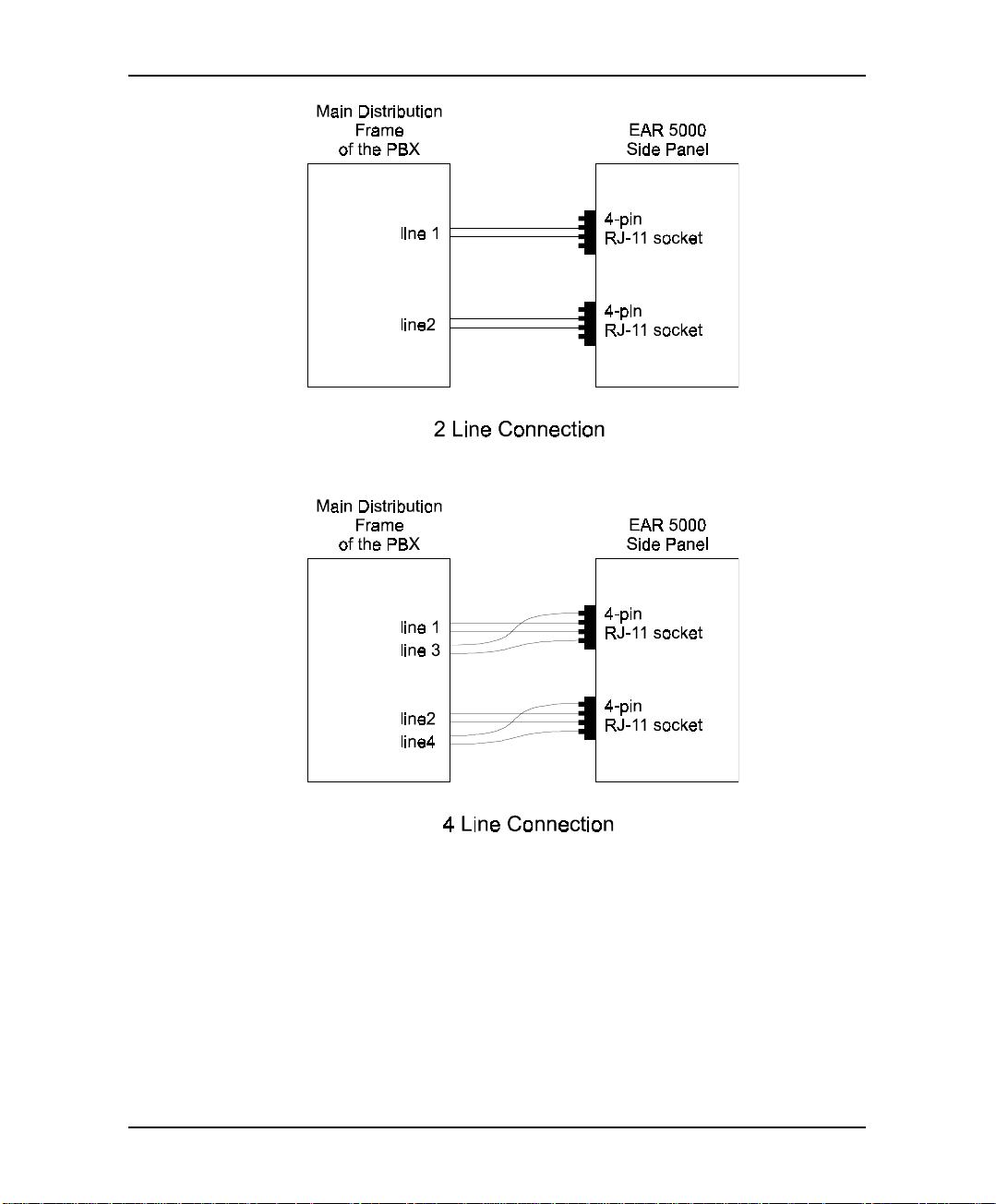
Description and Installation
Figure 2-5 Analog Line Connections
4. On the side panel of the EAR 5000, plug the 9V DC adapter jack into the
power supply connector.
5. Plug the 9V DC adapter into the main power supply outlet to turn the EAR
5000 on. The LED’s on the front panel turn on and off, one after another
and then the LED indicating the status of the EAR 5000 turns on.
2-6 Installation and Programming Manual
Description and Installation
6. If your PBX supports full-authorized RS-232 integration with the EAR
5000, connect one end of the RS-232 cable to the EAR 5000’s RS-232
connector and the other end to the RS-232 connector of the PBX.
7. Call each EAR 5000 line from any extension and verify the answer. You
should hear the default greeting (system m essag e no. 000. See Appendix C).
8. Replace the side panel cover.
9. Program the EAR 5000 according to your PB X type and required
applications.
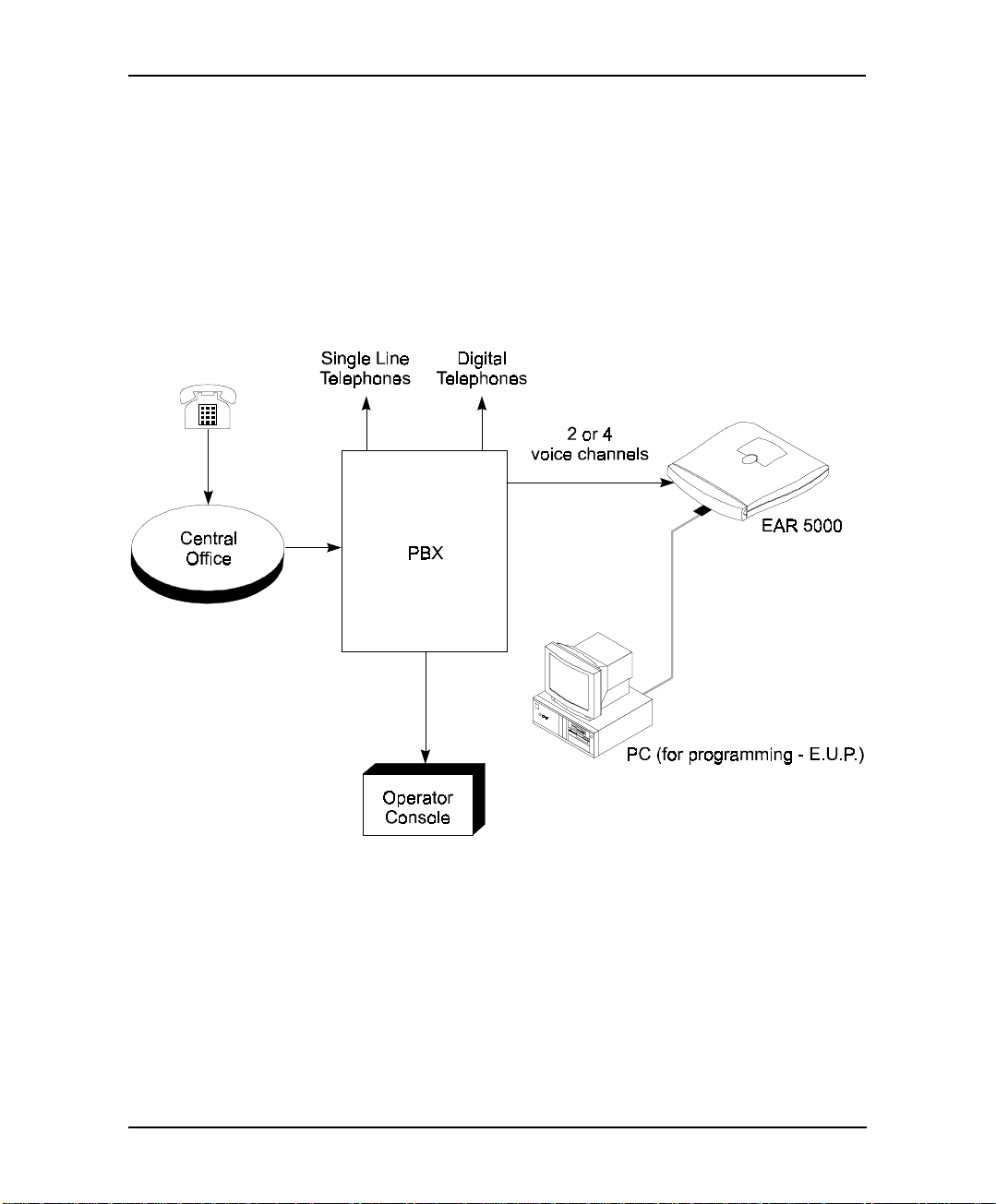
Figure 2-6 System Installation
Installation and Programming Manual 2-7

Description and Installation
2.3.3 Expanding the System
2.3.3.1 Expanding to Four Lines
The two-line expansion kit contains:
• 2-line expansion card
• 4-wire cable
• Two plastic spacers
! To install the expansion card:
1. Disconnect all external cables and connectors.
2. Remove the 9V DC adapter power plug from the main power supply outlet
to turn the EAR 5000 off.
3. Open the EAR 5000’s top cover by unscrewing the four screws.
4. Place the two plastic spacers into the corresponding holes.
5. Insert the expansion card into the corresponding J6 connector.
6. Connect one end of the 4-wire cable to J5 on the motherboard and the
other end to J5 on the expansion card.
7. Replace the top panel cover and plug the 9V DC adapter into the main
power supply outlet to turn the EAR 5000 on.
8. Reconnect all the external cables and connectors to the EAR 5000.
EAR 5000 automatically detects four lines when it is turned on.
2-8 Installation and Programming Manual

3. DTMF PROGRAMMING
The EAR 5000 can be programmed by:
• Telephone using DTMF tones
• Computer using the EAR Utility Program (see Section 4)
This section describes programming the EAR 5000 using DTMF tones.
Note: You will hear a confirmation tone every time you enter a programming
command.
3.1 Entering and Exiting the Programming Mode
The EAR 5000 does not handle calls when in the programming mode.
! To enter the programming mode:
1. Connect a PBX analog line to the EAR 5000.
2. Call the PBX analog line from any touch-tone telephone.
3. Wait until the EAR 5000 answers and plays the opening menu. Then dial
*900.
4. Dial the System Administrator’s password (the default password is 1234)
to enter the programming mode.
! To exit the programming mode:
• Dial *900.
–or–
Do not dial for one minute.
Note: If you exit the programming mode by dialing *900, the EAR 5000 plays the
opening menu and you can then test the changes made to the system.
Installation and Programming Manual 3-1
DTMF Programming
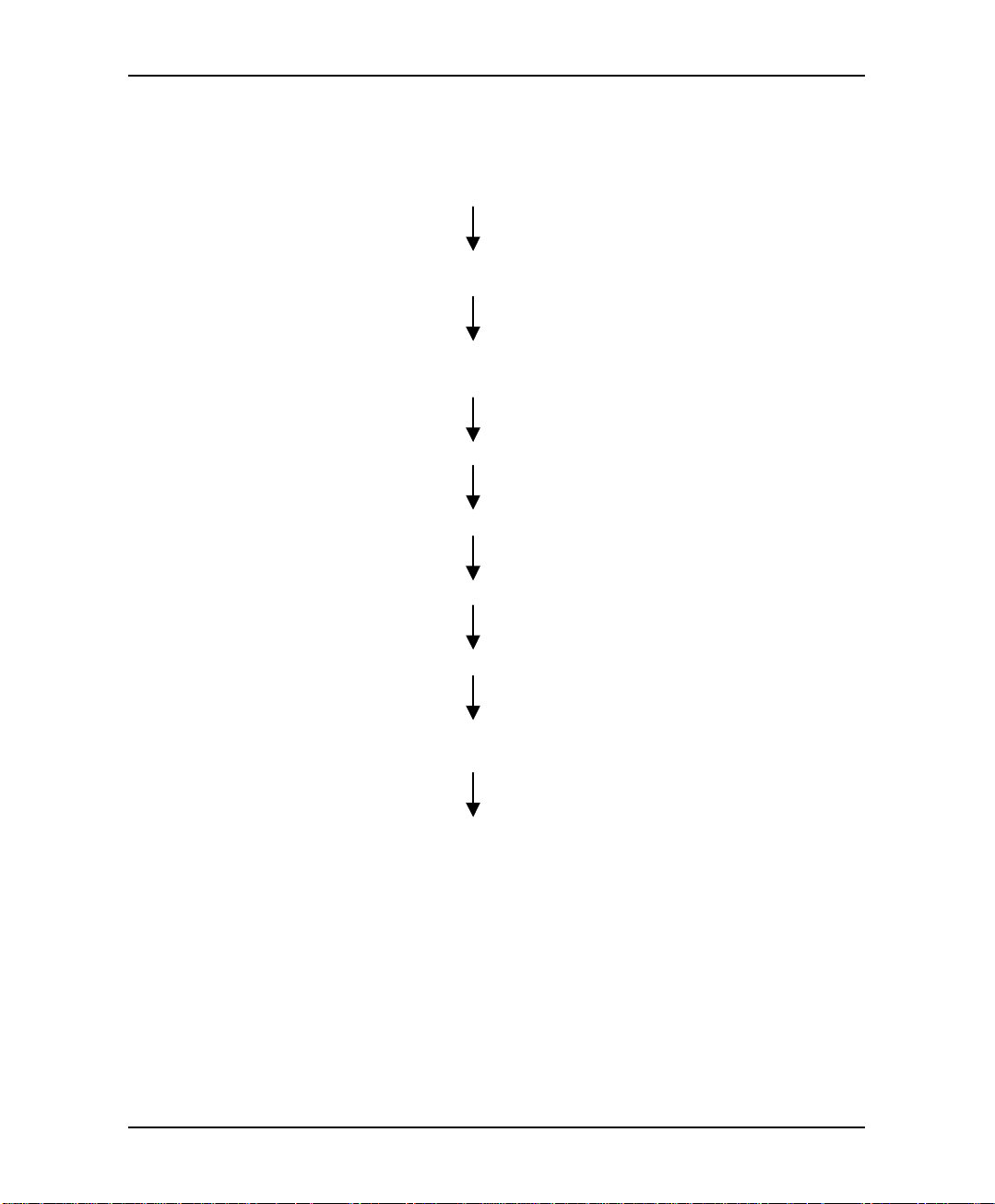
3.2 First Time Programming Checkl i st
1. Call from a touch-tone telephone to the EAR 5000. You will hear the default
message (system message 000 - see Appendix C).
2. Dial *900 and the administrator password (default: 1234) to enter the
programming mode.
3. Set the PBX parameters (see Sections 3.3 and Section 6) to ensure the proper
operation of the EAR 5000 with your PBX.
4. Set the EAR 5000’s real-time clock (see Section 3.4).
5. Set the system schedule (see Section 3.5).
6. Create mailboxes (see Section 3.6.1).
7. Define a notification type for each mailbox (see Section 3.6.3).
8. Define notification parameters (i.e., message light on and message light off
and interval between ring notification in Section 3.6.3.)
9. Record (see Section 3.7.1) and program (see Section 3.7.2) script menus for
the Automated Attendant. Make sure you define the mailboxes before building
Automated Attendant script menus.
3-2 Installation and Programming Manual

DTMF Programming
3.3 Defining PBX Parameters
To integrate the EAR 5000 with your PBX, apply the PBX parameters to the EAR
5000.
To obtain your current PBX parameters, check your PBX User’s Manual or the
current PBX setup configuration.
To configure the EAR 5000 to detect the in-band DTMF protocol sent by your
PBX, refer to Section 6.
Note: Do not forget to enter programming mode by dialing *900 and the
administrators password before using the programming commands.
Table 3-1 presents the commands you must enter to apply the PBX parameters to
the EAR 5000.
Table 3-1 PBX Parameter Commands
OPERATION COMMAND DEFAULT
Extension size
Cut off time for
continuous call
progress tone
detection
No. of rings
before the line is
answered
Time to wait for
No-Answer
*300 + X
where X is a digit 1-4
You can only change this parameter if mailboxes
and/or lega l extensions have not yet been defined .
*301 + X
where:
X = cut off time in seconds (0-9)
*310 + line number + number of rings
Line number = 1-4
Number of rings = 1-9
*311 + XX
where XX is 00-99 seconds.
This code is applicable only when supervised
transfer is selected.
3
6 seconds
1
20 seconds
Installation and Programming Manual 3-3

DTMF Programming
Table 3-1 PBX Parameter Commands (continued)
OPERATION COMMAND DEFAULT
Legal PBX
Extensions
Resetting a group
Resetting all
groups
Operator ID Code
Programmable
code for retrieving
messages
Disconnection
Code
*320 + Y + First Ext. + Last Ext. + #
where Y is a group number (0-9).
Example: *320 0 330 350 #
*320 1 355 375 #
You can define up to 10 groups of legal exte nsions.
If a caller dials an extension by direct dialing (code
170), The EAR 5000 checks if the extension is
legal. If the extension is not legal, The EAR 5000
does not transfer the call.
*320 + Y + 000 + 000 + # (the two groups of zeros
can be 2, 3, or 4 digits long, according to the
extension size)
*320 + #
*330 + X
where X is a digit 0-9
When the caller dials this digit during any script
message, the call is transferred to the operator.
*331 + X
X = 0-9; Retrieve digit
1
*333 + CODE
+ #
The EAR 5000 terminates a call when it receives
the disconnection code. The code can include up to
four digits. Legal values for this code can be any
combination of 0-9, *, #, and A-D.
None
0
9
###
Clear
* 333 + #
Disconnection
Code
External Access
Code
*340 + X + #
where X is the external access code (0-9), Pause
9
(*1).
This code is applicable for external notification.
Clear External
*340 + #
Access Code
3-4 Installation and Programming Manual

DTMF Programming
Table 3-1 PBX Parameter Commands (continued)
OPERATION COMMAND DEFAULT
Pause before and
after external
access code
Transfer mode for
all extensions
Day operator,
Night operator,
Fax and
Supervisor’s
extension numbers
Delete the
extension
assignments
*341 + X
where X is the length of the pause in seconds (0-9)
*350 + X + Y
X = 1; All extensions except the operator
X = 2; Operator extension only
Y = 0; Non Supervised
Y = 1; Supervised Mode
Y = 2; Semi Supervised mode
*360 + X + YYYY + #
where:
X = 1; Day operator
X = 2; Night operator
X = 3; Fax extension
X = 4; Supervisor extension
One mailbox can be defined as Supervisor. When
storage memory reaches 80% of its capacity, a
message is sent to this mailbox indicating the
situation.
YYYY = Corresponding extension number.
*360 + X + #
where:
X = 1; Day operator
X = 2; Night operator
X = 3; Fax extension
X = 4; Supervisor extension
2 seconds
Non
supervised
0
0
–
–
Volume level
Flash-1
Flash-2 Flash-2 is fixed at 1200 ms.
Installation and Programming Manual 3-5
*369 + X
where:
X = volume level (0-9), 9 = Loudest
*370 + XXX
where XXX is a 3-digit number (000-980) in steps
of 20 ms.
Example: *370 300 sets Flash-1 to 300 ms
Flash-2 is used in some PBX’s for Recall from NoAnswer or Busy Codes.
5
600 ms
1200 ms
 Loading...