

Page 1

OmniSwitch/Router
Getting Started Guide
TM
April, 2004
Page 2

Safety Information:
Omni Switch/Router™ hardware installation and maintenance is to be provided by Customer Support
personnel, or equivalent, knowledgeable in basic electrical and mechanical safety procedures.
Safety Information for Rack Mounting:
Switches should be installed in a maximum 40˚ C environment. To ensure proper air
flow, it is recommended that the switches have at least two inches of clear space on all sides. To ensure stability, precautions should
be taken to prevent uneven loading of the rack. Loading of the rack should begin at the bottom. When multiple components are
installed, precautions should be taken to prevent overloading of power outlets. The switches should always be properly grounded.
Lithium Batteries Caution:
There is a danger of explosion if the Lithium battery in your chassis is incorrectly replaced.
Replace the battery only with the same or equivalent type of battery recommended by the manufacturer. Dispose of used
batteries according to the manufacturer’s instructions. The manufacturer’s instructions are as follows:
Return the module with the Lithium battery to Alcatel. The Lithium battery will
be replaced at Alcatel’s factory.
All-In-OneSM Service Programs:
An Alcatel service agreement brings your company the assurance of 7x24 no-excuses
technical support. You’ll also receive regular software updates to maintain and maximize your Alcatel product’s features and
functionality and on-site hardware replacement through our global network of highly qualified service delivery partners.
Additionally, with 24-hour-a-day access to Alcatel’s Service and Support web page, you’ll be able to view and update any case
(open or closed) that you have reported to Alcatel’s technical support, open a new case or access helpful release notes,
technical bulletins, and manuals. For more information on Alcatel’s Service Programs, see our web page at
www.ind.alcatel.com, call us at 1-800-995-2696, or email us at support@ind.alcatel.com.
The features and specifications described in this manual are subject to change without notice.
Alcatel Internetworking
26801 West Agoura Road
Calabasas, CA 91301
(818) 880-3500 FAX (818) 880-3505
info@ind.alcatel.com
US Customer Support: (800) 995-2696
International Customer Support: (818) 878-4507
Internet–http://eservice.ind.alcatel.com
Copyright
document may not be reproduced in whole or in part without the express
written permission of Alcatel Internetworking, Inc.
Alcatel
OmniSwitch
Alcatel Internetworking, Inc. AutoTracker™, OmniAccess™, OmniCore™,
Omni Switch/Router™, OmniVista™, PizzaPort™, PolicyView™,
RouterView™, SwitchManager™, SwitchStart™, VoiceView™, WANView™,
WebView™, X-Cell™, X-Vision™ and the Xylan logo are trademarks of Alcatel
Internetworking, Inc. All-In-One
Internetworking, Inc. All other brand and product names are trademarks of
their respective companies.
©
2004 by Alcatel Internetworking, Inc. All rights reserved. This
®
and the Alcatel logo are registered trademarks of Alcatel. Xylan®,
®
, PizzaSwitch® and OmniStack® are registered trademarks of
SM
is a service mark of Alcatel
Page 3

Table of Contents
Installing Your Switch
Unpack the Switch . . . . . . . . . . . . . . . . . . . . 1
Re-Seat Switching Modules . . . . . . . . . . . . . . 1
Removing the Modules . . . . . . . . . . . . . . 2
Re-Installing the Modules . . . . . . . . . . . . 4
Find a Safe, Well Ventilated Location . . . . . . 4
Mount the Switch (Optional) . . . . . . . . . . . . 4
Rack Mounting the Chassis . . . . . . . . . . . . . . 5
Wall Mounting the Chassis (3-Slot) . . . . . . . . 6
Connect the Power Supply . . . . . . . . . . . . . . 7
Connect to the Serial Port . . . . . . . . . . . . . . . 7
Power On the Switch . . . . . . . . . . . . . . . . . . 8
Verify LEDs . . . . . . . . . . . . . . . . . . . . . . . . . 8
Omni Switch/Router MPX . . . . . . . . . . . . 8
Omni Switch/Router Switching
Modules . . . . . . . . . . . . . . . . . . . . . . . 8
Log In to the Command Line Interface
(CLI) . . . . . . . . . . . . . . . . . . . . . . . . . . . . . 9
Set Up a Password . . . . . . . . . . . . . . . . . . . 10
Set the System Time and System Date . . . . . 11
Enter a System Description (Optional) . . . . 12
Assign an IP Address to the Default
Group . . . . . . . . . . . . . . . . . . . . . . . . . . . 14
Log Out . . . . . . . . . . . . . . . . . . . . . . . . . . . 15
Connect the Devices . . . . . . . . . . . . . . . . . 15
. . . . . . . . . . . . . . . . 1
OmniS/R Basics
Omni Switch/Router Chassis . . . . . . . . . 16
The Management Processor Module
(MPX) . . . . . . . . . . . . . . . . . . . . . . . . 18
Flash Memory and Switch Software . . . . 20
Switching Modules . . . . . . . . . . . . . . . . 21
. . . . . . . . . . . . . . . . . . . . . . 16
The User Manual on CD
Notes
. . . . . . . . . . . . . . . . . . . . . . . . . . . . . . . 23
. . . . . . . . . . . . . . 22
Table of Contents
iii
Page 4

iv Table of Contents
Page 5

Installing Your Switch
This chapter walks you through the initial steps needed
to set up Omni Switch/Router™ hardware and software. These steps show you how to:
• Set up and power on your switch
• Connect a network management station
s reflect normal operation
• Verify that the
• Configure system software parameters, including
an IP address for the switch
By the end of this chapter, you will be ready to use
switch software to begin configuring
and individual switching module parameters. You will
also be able to start monitoring a wide array of statistics. Consult your
more advanced configuration and management of your
switch.
LED
s, routing,
VLAN
Omni Switch/Router User Manual
for
1. Unpack the Switch
Remove all hardware from the packing boxes and
inspect each item to ensure there has been no shipping damage. In addition, ensure the packing boxes
contain all the items that you ordered. If you discover
or suspect any damage, contact your distributor immediately.
♦
Warning
Do
not
install OmniSwitch modules in
an Omni Switch/Router chassis. Only
Omni Switch/Router modules should
be installed in an Omni Switch/Router
chassis. If you install OmniSwitch
modules in an Omni Switch/Router
chassis, physical damage may result.
♦
2. Re-Seat Switching Modules
Switching modules may become slightly unsettled
during shipping. To ensure each module is properly
positioned, gently remove and reinsert each module
according to the instructions below.
Rack or Wall Mounting Your Switch?
You may want to keep the switching
modules that you remove from the
switch chassis out until you have
completed the mounting procedure.
Keeping the modules and power
supplies out of the chassis lightens the
weight of the chassis for the mounting procedure.
Installing Your Switch
1
Page 6

A flat blade screwdriver is required for installing and
removing switching modules
. In a chassis with horizontal slots, the slots are numbered sequentially with slot 1
being the topmost slot. In a chassis with vertical slots,
the slots are numbered sequentially with slot 1 being
the leftmost slot.
♦
Anti-Static Warning
♦
Before handling any module, free your
hands of static by wearing a grounding strip or by grounding yourself
properly. Static discharge can damage
the components on the module.
Removing the Modules
To remove a module, follow these instructions:
a. Loosen the screw fasteners at the top and bottom
of the module using a flat blade screwdriver.
2 Installing Your Switch
Page 7
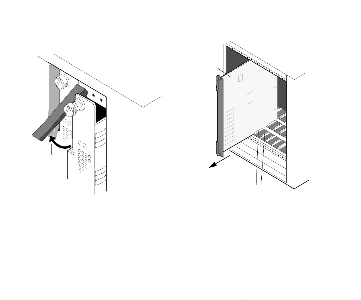
b. Gently unlock the two card ejectors (one on
each end of the module) by pressing them out
and away from the module.
Switching Module
Slide Card Out
Card Guides
c. Holding the module firmly in both hands, care-
fully slide it out of the chassis along the card
guide. The module should slide out easily. A
large amount of force is not necessary and
should not be used.
d. Repeat the above steps for all switch modules. If
you are rack or wall mounting the switch, you
should store the removed modules and power
supplies in a safe, anti static place and skip to
Step 3. If you are not rack or wall mounting the
switch, re-install the modules as described in the
next section.
Installing Your Switch 3
Page 8

Re-Installing the Modules
3. Find a Safe, Well Ventilated Location
To re-install modules, follow the instructions below:
a. Hold the module firmly in both hands, and care-
fully slide it into the card guide. Make sure the
front panel connectors and
a switch with vertical slots, the component side
of the board should face right. In a switch with
horizontal slots, the component side should face
up.
The module should slide in easily. A large
amount of force is not necessary and should not
be used. If any resistance is encountered, ensure
the module is aligned properly in the card
guide.
b. Once the module is in the slot, close the two
card ejectors (one on top of the module and one
on the bottom) by pressing them in toward the
module until they snap into place.
c. Use a flat blade screwdriver to tighten the two
screw fasteners to secure the module inside the
chassis. The screws should be tight enough that
a screwdriver would be necessary to loosen the
screws.
LED
s face outward. In
Find a space with adequate power source access and
ventilation where you can set up the switch. A standard office AC supply of 90 to 120 volts or 200 to 230
volts is required for normal operation. Be sure that
adequate ventilation exists in the vicinity of the unit.
Also, be careful not to block the ventilation holes on
the sides or back of the unit.
The Omni Switch/Router is designed to operate in an
office environment. The enclosure and all modules are
safe to handle, and the noise level meets the requirements for an office environment.
4. Mount the Switch (Optional)
All switches are shipped with brackets and bracket
screws for rack mounting the chassis. (Rack-mount
screws, which attach the brackets to the rack, must be
purchased from your rack vendor). You can order
wall-mounting brackets for a 3-Slot chassis separately.
♦
Note
A Phillips screwdriver is required for rack
or wall mounting procedures, and a drill
is required for wall mounting the chassis.
♦
4 Installing Your Switch
Page 9
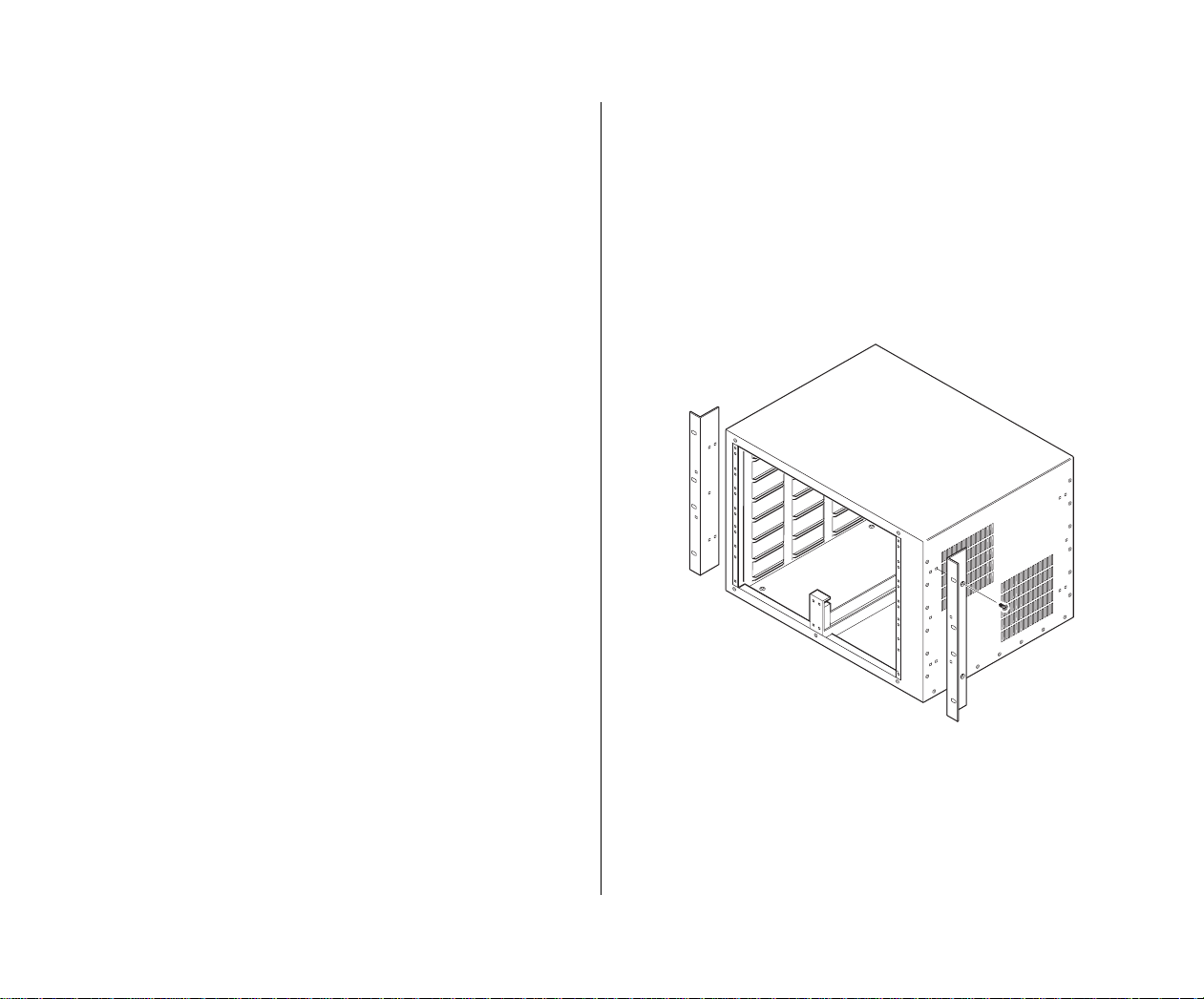
Rack Mounting the Chassis
Follow these steps to mount a switch chassis in a rack:
The following sections provide instructions for rack
mounting the switch chassis.
♦
Lighten the Load
Before you mount an Omni Switch/
Router chassis, remove the switching
modules and power supplies to
lighten the weight of the chassis. Refer
to Step
on page 1 for instructions.
To rack mount a switch chassis, the following items are
required:
• 2 rack-mounting brackets (included)
• Phillips flat-head 100 degree screws (included)
• Phillips screwdriver (not included)
9-slot Omni Switch/Router in a Rack
If you want to install a 9-slot Omni
Switch/Router in a rack, we recommend
placing it on a rack shelf in addition to
mounting it with brackets and screws.
2. Re-Seat Switching Modules
♦
a. Select a shelf on the rack that allows easy access
to the switching modules and power supplies
once the chassis is mounted.
b. Attach one rack-mounting bracket to the front
end of the chassis using the Phillips-head screws
that came with the chassis. See the figure below
for the positioning and placement of these
brackets and screws.
Installing Your Switch 5
Page 10

c. Attach the second bracket to the opposite front
end of the chassis using the remaining screws.
d. Carefully lift the chassis and insert it into the
rack.
e. Attach both brackets to the rack by screwing in
the rack screws.
Wall Mounting the Chassis (3-Slot)
To wall mount a 3-slot switch chassis, the following
items are required:
• 2 wall-mounting brackets (optional)
• Phillips flat-head 100 degree screws (included)
• Standard, wall-mounting screws (not included)
• Drill (not included)
• Phillips screwdriver (not included)
♦
Note
Only the 3-slot version of the Omni
Switch/Router can be wall mounted.
The 5-slot and 9-slot models cannot be
wall mounted.
Follow these steps to wall mount a switch chassis:
a. Locate an area that allows easy access to the
switching modules and power supply once the
chassis is mounted.
♦
6 Installing Your Switch
Caution
The weight of a fully-loaded 3-slot
chassis is approximately 18 lbs. (8.18
kg.). Be sure to choose a suitable
location that can support the weight
of the fully-loaded chassis.
Page 11

b. Use the holes in the wall-mounting bracket and
the chassis as a guide, measure the correct
placement for the wall-mounting screws.
c. Drill holes in the wall for the wall-mounting
screws.
d. Screw the wall-mounting screws into the wall.
e. Attach one bracket to the back end of the chas-
sis, using the Phillips flat-head screws that came
with the chassis.
5. Connect the Power Supply
Attach a power cord to one or more of the power
supplies. The power supplies are located in the bottom
bays of the chassis.
When more than one power supply is used, they act as
redundant, power-sharing power sources. During
normal operation the power supplies share the power
load. In the event one power supply fails, the other
acts as a back up and picks up the power load from
the failed power supply.
♦
Power Cord Safety Precautions
In the event that your power cord is
lost or damaged, refer to the
Switch/Router User Manual
Omni
for instruc-
tions on how to obtain a replacement.
♦
f. Attach the second bracket to the opposite back
end of the chassis using the remaining screws.
g. Carefully lift the chassis and hang it on the wall-
mounted screws.
European cords
HAR
(
) type. See the
Router User Manual
must
be Harmonized
Omni Switch/
for further infor-
mation.
6. Connect to the Serial Port
Attach a serial cable to the female serial port connector on the
end of the serial cable to a workstation equipped with
terminal emulation software. You will use this connection to enter initial configuration values for the switch.
Later you can use this connection to perform more
sophisticated network management tasks, such as
configuring
statistics.
MPX
module’s front panel. Connect the other
VLANs
, setting up routing, and monitoring
Installing Your Switch 7
Page 12

The Console Management ports are
RS-232
ports used
to interface with switch software. One port, called the
“modem” port, is a male
called the “console” port, is a female
They are each 9-pin “D” (
conform to the
IBM AT
connecting device does not conform to the
DTE
connector and the other,
DTE
connector.
DB-9
) connectors that
serial port specification. If the
IBM AT
serial port specification, you may need a special cable
or adapter.
7. Power On the Switch
Turn the power supply On/Off switch to the On (I)
position.
All modules are subjected to extensive power-on diagnostics during the Power-On Self-Test cycle (
POST
). For
this reason, you should allow the switch several
seconds to perform preliminary tests before evaluating
the
OK2
LEDs
. While the diagnostics are running, the
LED
will blink Amber. When diagnostics are
MPX
complete and all modules are operating correctly, the
OK1
LED
on all modules should be on solid Green and
LED
OK2
the
below summarize how
should be blinking Green. The tables
LED
s should display in normal
operation.
Omni Switch/Router MPX
LED Normal State Comments
8. Verify LEDs
Check that
cate a normal state of operation. On an
LED
should be on steady Green if one power supply is
inserted. If two power supplies are installed, both the
PS1
and
8 Installing Your Switch
LED
s on the front panel of the chassis indi-
LEDs
PS2
should be on solid Green.
MPX,
the
PS1
PS1
PS2
Green
On Steady
If the corresponding power
supply is turned off, the
LED will be On Amber
Steady.
OK1 Green
On Steady
OK2 Green
Blinking
Hardware diagnostics
passed.
Blinks amber while diagnostics are running.
Omni Switch/Router Switching Modules
LED Normal State Comments
OK1 Green
On Steady
OK2 Green
Blinking
Hardware diagnostics
passed.
Blinks amber while diagnostics are running.
Page 13

9. Log In to the Command Line Interface (CLI)
If you are using one of the
terminal emulation software package to establish a
session with the switch. Configure your terminal
emulation software parameters as follows:
• 9600 baud
• 8 data bits
• 1 stop bit
• no parity
• no hardware flow control (Windows 95 or later)
After the system has booted, the Login prompt is
displayed:
Welcome to the Alcatel Omni Switch/Router!
Version x.x.x.x
login :
Initially, there are three types of login accounts available on the Omni Switch/Router:
admin
The
functions. The
and
diag
accounts allow full access to all
diag
account additionally supports a set
of switching module tests (see the “Running Hardware
Diagnostics” chapter in your
Manual
for details). The
privileges. All three accounts use
password.
MPX’s
serial ports, use a
admin, diag
Omni Switch/Router User
user
account allows read-only
switch
as the default
and
user
.
♦
Important Note
♦
If you have Administrative (WRITE)
privileges on the switch, you can
create or delete logins and new user
accounts with administrative privileges.
♦
Partition Management ♦
Partition Management allows you to
restrict access to particular switch
features on a per user basis. See the
“Switch Security” chapter in your
Omni Switch/Router User Manual
for
details.
The following procedure uses the
admin
login account
as an example. Complete the following steps to log in
to the switch.
♦
Caution
♦
If the system displays the following
prompt:
Please Standby, chassis configuration changing
(Hit ^C to abort)...
it means you are attempting to access
the switch before it has completed
initialization or processing a previous
command. Wait until the switch
displays the login prompt before
entering any commands.
Installing Your Switch 9
Page 14

<Enter>
admin
at the login prompt and press
.
The following prompt displays:
password:
switch
at this prompt and press
<Enter>
.
a. Enter
b. Enter
When you have successfully logged in, the
screen will display similar to the following.
**************************************************************************************
Alcatel Omni Switch/Router
Copyright (c), 1994 - 2002 Alcatel Internetworking, Inc. All rights reserved.
Omni Switch/Router is a trademark of Alcatel Internetworking, Incorporated,
registered in the United States Patent and Trademark Office.
Press ENTER to start
The Omni Switch/Router is factory-configured to boot
up in
CLI
(Command Line Interface) mode. The
CLI
allows you to enter single-line commands through the
local console. (For more information on CLI, see your
Text-Based Configuration Reference Manual.)
♦ Configuration Modes ♦
You can also configure your switch
through the User Interface (
enter the User Interface, type ui at the
CLI prompt (->) and press <Enter>.
The UI prompt (/=>) will be
displayed, indicating that you are in
UI mode. From here, you can type ?
and press <Enter> to view the Main
Menu. (For more information on using
the UI, refer to your Omni Switch/
Router User Manual.)
To return to
CLI mode from UI mode,
type either cli or exit at the UI prompt
(/=>) and press <Enter>.
10. Set Up a Password
UI). To
To start the Command Line Interface, press
<Enter>.
The following message and CLI prompt (->) will be
displayed, to indicate that you are in CLI mode:
Entering Command Line Interface
->
10 Installing Your Switch
Before you configure the connections for your switch,
you should set up a password for the admin login
account. The admin login account provides full access
to all switch management functions.
The factory default password for the
switch. Follow these steps to change the password for
admin account is
the admin account:
a. Type
password admin <old_password >
<new_password>
<Enter>. For example, to change the factory
at the CLI prompt and press
default password (switch) to a new password (for
example,
lahaina), enter the following:
-> password admin switch lahaina
Page 15

b. No confirmation message will appear onscreen.
Only the system prompt (->) will appear.
♦ Important Notes ♦
The
admin, diag and user accounts
use switch as the default password.
For security purposes, the default
password should be changed for
these accounts.
To create an all-numeric password (for
example,
7654321), you must enter
double quotation marks before and
after the password 7654321.
All new passwords take effect at your next login
session.
11. Set the System Time and System Date
Complete the following steps to set the time and date:
a. To view the system time, type
CLI prompt and press <Enter>. The system time
will be displayed, as shown in the example
below:
-> system time
10:53:19
b. To set the system time, type system time
hh:mm:ss
at the CLI prompt and press <Enter>.
The new system time will be displayed, as
shown in the example below:
-> system time 11:53:19
system time at the
♦ Caution ♦
Your password is stored (encrypted)
mpm.cnf configuration file. If
in the
you remove this file and reboot the
switch, your login password (as well
as all user-configured data) will automatically reset to the factory default. In
this event, you must start over from
Step a (see column at left) to change
the password.
New time: 11:53:19
c. To view the system date, enter system date at the
CLI prompt and press <Enter>. The system date
will be displayed, as shown in the example
below:
-> system date
06/11/02
d. To change the system date, enter system date
mm/dd/yyyy
at the CLI prompt and press <Enter>.
The system date will be displayed, as shown in
the example below:
-> system date 06/12/2002
New date: 06/12/02
Installing Your Switch 11
Page 16

12. Enter a System Description (Optional)
You can use the following CLI commands to view or
specify a contact person for the switch, a switch name,
its location, a description of the switch, and the
switch’s MAC aging timer value. Although this information is not required, you may find it helpful for managing the switch. Use the following procedure:
a. To view the department or network administrator
for the switch, type
CLI prompt and press <Enter>. If no network
administrator has been specified, the following
will be displayed:
-> system admin-contact
Unset
system admin-contact at the
♦ Important Notes ♦
To add spaces between words, you
must include quotation marks (
“ ”)
around the text string when entering
the admin-contact information.
No confirmation message will appear
onscreen. To verify that the system
admin-contact information has been
set, type
CLI prompt and press <Enter>.
c. To view the system name, type
system admin-contact at the
system name at
the CLI prompt and press <Enter>. If no name
has been specified, the following will be
displayed:
-> system name
b. To specify the department or network adminis-
trator for the switch, type system admin-contact
followed by the contact information (text string)
you want to use at the CLI prompt and press
<Enter>. For example, to specify Networking Corp
Customer Service (800-555-6000)
as the admincontact information, type the following at the
CLI prompt and press <Enter>:
-> system admin-contact “Networking Corp
Customer Service (800-555-6000)”
12 Installing Your Switch
Unset
d. To specify the system name, type system name
followed by the name (text string) you want to
use at the CLI prompt and press <Enter>. For
example, to specify Sales as the system name,
type the following at the CLI prompt and press
<Enter>:
-> system name Sales
Page 17

♦ Important Notes ♦
The system name must be a single
word or hypenated text string. Do not
use commas, quotation marks or
underscores.
g. To view the system description, type
description
at the CLI prompt and press <Enter>.
If no description has been specified, an error
message will appear, as shown below:
-> system description
system
No confirmation message will appear
onscreen. To verify that the system
name has been set, type
system name
at the CLI prompt and press <Enter>.
e. To view the system location, type
location
at the CLI prompt and press <Enter>. If
system
no location has been specified, the following
will be displayed:
-> system location
Unset
f. To specify the system location, type system
location
followed by a text-string name you want
to use at the CLI prompt and press <Enter>. For
example, to specify Calabasas Test Lab as the
system location, type the following at the CLI
prompt and press <Enter>:
-> system location “Calabasas Test Lab”
♦ Important Notes ♦
Any text-string name that includes
spaces must be enclosed in quotes
(e.g.,
“Test Lab”).
DESCRIPTION NOT SET.
h. To specify the system description, type system
description
followed by a text-string you want to
use at the CLI prompt and press <Enter>. For
example, to specify Engineering #2 as the system
description, type the following at the CLI prompt
and press <Enter>:
-> system description “Engineering #2”
♦ Important Notes ♦
To add spaces between words, you
must include quotation marks (
“ ”)
around the text string for system
description
.
No confirmation message will appear
onscreen. To verify that the system
description has been set, type
description
<Enter>.
at the CLI prompt and press
system
No confirmation will appear onscreen.
To verify that the system location has
been set, type
CLI prompt and press <Enter>.
system location at the
Installing Your Switch 13
Page 18

i. The MAC aging timer indicates how many
seconds any duplicate MACs can remain in the
switch’s CAM (Content Addressable Memory) if
there is no traffic from those MACs. After the
specified time has expired, inactive MACs age
out of the CAM. To view the switch’s MAC aging
timer value (default=0), type system dup-mac-
timer
at the CLI prompt and press <Enter>, as
shown in the example below:
-> system dup-mac-timer
0
j. To specify the switch’s MAC aging timer value in
seconds, type system dup-mac-timer followed by a
number of seconds (the valid range is 10
through 1000000 seconds) at the CLI prompt and
press <Enter>. For example, to specify 5000 as
the MAC aging timer value, type the following at
the CLI prompt and press <Enter>:
-> system dup-mac-timer 5000
♦ Important Notes ♦
Do not use commas when specifying a
MAC aging timer value. For example,
the entry 63,000 will result in an error.
13. Assign an IP Address to the Default Group
All switches are configured with a default Group and
VLAN. You can add Groups and VLANs later through
the switch software. To get started, you can use the
default group and default VLAN to configure the IP
address for this switch. (The default IP address is
192.168.10.1.) To modify Group IP routing parameters,
complete the following steps:
a. To assign or modify the default Group and
Address, type the following at the CLI prompt
and press <Enter>:
-> group 1 router ip < ip-address >
where 1 is the default group and VLAN, and
< ip-address > is the IP Address for a specific
virtual router port (for example, 168.23.9.100).
b. No confirmation message will appear onscreen.
Only the system prompt (
->) will appear.
See your switch manual to set other parameters.
VLAN
If you want to use the Group aging
timer, enter
aging timer.
No confirmation message will appear
onscreen. To verify that the switch’s
MAC aging timer has been set, type
system dup-mac-timer at the CLI prompt
and press <Enter>.
14 Installing Your Switch
0 as the value for the MAC
Page 19

You have now set up all of the basic software parameters you need to begin managing your switch. Once
your switch is connected to the network, you can use
Telnet or FTP to access the switch software through
your network.
More Information on Switch Commands?
At this point, you can begin configuring other switch parameters. See your
Omni Switch/Router User Manual and
any manual supplements that came
with your Omni Switch/Router for
information on all switch commands.
14. Log Out
When you are finished using switch commands
through the Command Line Interface, you can exit the
switch by entering logout or exit and pressing <Enter>.
15. Connect the Devices
Connect the devices (e.g., computers, printers, servers)
to the appropriate Omni Switch/Router ports.
More Information on Switch Hardware?
Your Omni Switch/Router User Manual
and any manual supplements that
may be included with your Omni
Switch/Router provide information on
all pieces of switch hardware. Refer to
those documents for more detailed
information.
Installing Your Switch 15
Page 20

OmniS/R Basics
This chapter provides basic information on Omni
Switch/Router (OmniS/R) chassis types, the Management Processor Module (MPX) and switching modules
used in Omni Switch/Router chassis. For more detailed
information, refer to the Omni Switch/Router User
Manual.
Omni Switch/Router Chassis
The Omni Switch/Router comes in 3-slot, 5-slot and
9-slot chassis types. All chassis support LAN and WAN
switching modules, such as Ethernet (ESX-K), Gigabit
Ethernet (GSX-K), WAN (WSX), and voice (VSX)
modules.
♦ Warning ♦
If you have a five-slot chassis with a
single power supply, do not remove
the cover on the empty power supply
slot. In addition, if you have any
empty switching module slots in either
a three-slot or five-slot Omni Switch/
Router chassis, you must cover them
with blank panels (available from
Alcatel) to prevent your chassis from
overheating.
Covering empty slots forces air to flow
directly over the power supplies,
thereby cooling them. If the power
supplies are not properly cooled, they
will overheat and shut down.
Switching Modules
Management Processor Module (MPX)
Built-in Power Supply
16 OmniS/R Basics
3-slot Omni Switch/Router
Page 21

.
Management Processor Module (MPX)
Switching Modules
PS1 (Power Supply 1)
Management Processor Module (MPX)
Switching Modules
Fan Tray
PS2 (Power Supply 2)
5-slot Omni Switch/Router
PS1 (Power Supply 1) PS2 (Power Supply 2)
9-slot Omni Switch/Router
OmniS/R Basics 17
Page 22

The Management Processor Module (MPX)
MPX offers the following features:
The
The MPX is the core of Omni Switch/Router’s distributed management functionality. It provides system
services such as configuration information, bridge
management functions, basic routing functions, the
SNMP management agent, and access to both the
Command Line Interface and User Interface software.
Switching modules are dependent on the
MPX for
downloading software and receiving initialization and
configuration information. In addition, Network
Management Software (NMS), such as X-Vision,
depends on the MPX to send and receive SNMP
messages for managing the switch.
MPX modules support a redundant configuration, so
that if one MPX fails, the other MPX automatically
assumes all management responsibilities.
MPX Features and Options
Backplane (MVBUS) Speed Up to 22 Gbps
Standard Flash Memory 8 MB or 16 MB
(16 MB required for
Release 4.4 and
later)
(16 MB maximum)
Standard DRAM 32 MB or 64 MB
(64 MB required for
Release 4.4 and
later)
(64 MB maximum)
HRE-X Supported? Yes
Advanced Routing Supported? Yes
♦ VBUS Mode 1 & 2 Support ♦
Certain feature parameters (such as
QoS) are supported only when the
Omni Switch/Router chassis runs in
VBUS Mode 2. For VBUS Mode 2
support, your chassis must have only
new generation (Kodiak-based)
Ethernet modules and/or WSXs
installed.
18 OmniS/R Basics
The Omni Switch/Router runs in
VBUS Mode 1 for chassis configurations that use any early generation
(non-Kodiak based) Ethernet
modules.
Page 23

OK1 (Hardware Status). This dual-state LED
is on Green when the MPX has passed
power-on hardware diagnostics successfully.
On Amber when the hardware has failed
diagnostic tests. If the OK1 LED is alternating
Green and Amber, then file system compaction is in progress.
Caution
Do not power down the switch or
insert any modules while the OK1
LED is alternating Green and Amber.
If you do, file corruption may result
and you will not be able to restart
the switch.
OK2 (Software Status). Blinking Green when
the MPX has successfully loaded software to
the switching modules. Blinking Amber
when the MPX is in a transitional state, such
as when it first boots up. If the OK2 LED
blinks Amber for an extended period of time
(i.e., more than a minute), then you should
reboot the switch.
Caution
Do not insert or remove any modules
while the MPX OK2 LED is blinking
amber. If you do, file corruption may
result and you will not be able to
restart the switch.
Module
Status
LEDs
MPX 10
PRI (Primary MPX). On Green when this
MPX is the active, or controlling, MPX. It is
also on Green when this is the only MPX
installed in the switch.
OK1
OK2
PS2
PS1
SEC (Secondary MPX). On Green when this
MPX is the secondary MPX in a redundant
TEMP
SEC
PRI
Module
MODEM
Status
LEDs
MPX configuration. As the secondary MPX,
this module is in hot standby mode.
TEMP (Temperature). On Amber to warn
that the internal switch temperature is
approaching maximum operating limits.
Note that this LED comes on before the tem-
CONSOLE
LINK
COL
ACT
perature limit is reached.
PS1 (Power Supply 1 Status). This dual-state
LED is on Green when the switch is receiv-
ing the proper voltage from Power Supply
ETHERNET
1. It is on Amber when Power Supply 1 is
on, but not supplying the correct amount of
voltage to power the switch, or is installed
and turned off. The PS1 LED is Off when the
Power Supply 1 is not present.
PS2 (Power Supply 2 Status). This dual-state
LED is on Green when the Omni Switch/
Router is receiving the proper voltage from
Power Supply 2. It is on Amber when Power
Supply 2 is on, but not supplying the correct
amount of voltage to power the switch, or is
installed and turned off. The PS2 LED is Off
when Power Supply 2 is not present.
The Management Processor Module (MPX) LEDs
OmniS/R Basics 19
Page 24

Flash Memory and Switch Software
MPX 10
Label. This label will indicate the Ethernet
management port type. It will read either
OK1
OK2
PS2
PS1
MPX I0 mm (multimode fiber Ethernet port)
or MPX I0 (copper RJ-45 Ethernet port).
Flash memory on the MPX holds the Omni Switch/
Router’s executable images and configuration data for
each image file. When a switching module comes
online, the MPX downloads the appropriate image file
for that module to that module’s memory. Image files
TEMP
SEC
PRI
The MPX module includes one row of
MODEM
LEDs for the Ethernet management
port.
ACT (Activity). On Green when
data is transmitted or received on
CONSOLE
LINK
COL
ACT
ETHERNET
the Ethernet management port.
LINK (Link Status/Disabled). On
Port
Green continuously when a good
LEDs
cable connection exists. Off when
a good connection does not exist.
(those with the .img extension) contain executable
code for different switching modules.
Not all image files loaded in flash memory are
required—only those that must be used with the
switching modules in your Omni Switch/Router. You
can remove any files that are not required for your
Omni Switch/Router configuration by using the
rm
command and free up space in flash memory. If you
need any switch files at a later date, you can use FTP
to back up the files to a PC before you delete them
from the switch.
COL (Collision). On Yellow when
a collision has been detected on
the port.
The switch alters flash contents during execution when
a software command requests a configuration change,
when a remote administrator downloads a new executable image, or when the switch fails and a record of
the failure is written to flash memory.
Ethernet Management Port Slot.
Copper RJ-45 and fiber Ethernet
management ports are available for
rapid switch file transfers and network management functions.
For detailed instructions on these procedures, refer to
your Omni Switch/Router User Manual and any manual
supplements that came with your Omni Switch/Router.
Ethernet Management Port LEDs
20 OmniS/R Basics
Page 25

Switching Modules
LEDs on switching modules vary by the network inter-
face type and by a module’s application. However, two
LEDs are common to all switching modules. These
LEDs, OK1 and OK2, provide information on the hard-
ware and software status, respectively, of the module.
These two LEDs are located at the top of the modules,
as shown in the following figure.
GSX-K mm
OK1 (Hardware Status). On Green
O
K
1
O
K
2
1
2
L
R
T
I
X
X
N
K
Module
LEDs
when the module has passed diagnostic tests successfully. On Amber when
the hardware has failed diagnostics or
if the corresponding image file for the
module is not in flash memory.
OK2 (Software Status). Blinking Green
when the module software was down-
T
X
1
R
X
loaded successfully and the module is
communicating with the MPX. Blinking
Amber when the module is in a transitional state. On solid Amber if the
module failed to download software
from the MPX.
T
X
2
R
X
Switching Module LEDs
OmniS/R Basics 21
Page 26

The User Manual on CD
The CD that accompanies this Getting Started Guide
contains Alcatel user documentation, including the
Omni Switch/Router User Manual.
Documentation is in Portable Document Format (
and requires the Adobe Acrobat Reader program for
viewing. Acrobat Reader with Search is recommended
for its global search capabilities, and can be obtained
from the Adobe website (www.adobe.com).
To install the
Switch/Router User Manual and other Alcatel documentation, refer to the instructions printed on the CD’s
packaging.
CD and navigate through the Omni
PDF)
22 The User Manual on CD
Page 27

Notes
Notes 23
Page 28

24 Notes
 Loading...