

Page 1

Part No. 060211-10, Rev.E
June 2007
OmniSwitch 9000 Series
Hardware Users Guide
www.alcatel-lucent.com
Page 2

This user guide documents OmniSwitch 9000 Series
hardware, including chassis and associated components.
The specifications described in this guide are subject to change without notice.
Copyright © 2007 by Alcatel-Lucent. All rights reserved. This document may not be reproduced in whole
or in part without the express written permission of Alcatel-Lucent.
®
Alcatel-Lucent
OmniSwitch
and the Alcatel-Lucent logo are registered trademarks of Alcatel-Lucent. Xylan®,
®
, OmniStack®, and Alcatel-Lucent OmniVista® are registered trademarks of Alcatel-Lucent.
OmniAccess™, Omni Switch/Router™, PolicyView™, RouterView™, SwitchManager™, VoiceView™,
WebView™, X-Cell™, X-Vision™, and the Xylan logo are trademarks of Alcatel-Lucent.
This OmniSwitch product contains components which may be covered by one or more of the following
U.S. Patents:
•U.S. Patent No. 6,339,830
•U.S. Patent No. 6,070,243
•U.S. Patent No. 6,061,368
•U.S. Patent No. 5,394,402
•U.S. Patent No. 6,047,024
•U.S. Patent No. 6,314,106
•U.S. Patent No. 6,542,507
•U.S. Patent No. 6,874,090
26801 West Agoura Road
Calabasas, CA 91301
(818) 880-3500 FAX (818) 880-3505
support@ind.alcatel.com
US Customer Support—(800) 995-2696
International Customer Support—(818) 878-4507
Internet—service.esd.alcatel-lucent.com
ii June 2007
Page 3

Contents
About This Guide .......................................................................................................... ix
Supported Platforms .......................................................................................................... ix
Who Should Read this Manual? ........................................................................................ix
When Should I Read this Manual? .....................................................................................x
What is in this Manual? ...................................................................................................... x
What is Not in this Manual? ............................................................................................... x
How is the Information Organized? ..................................................................................xi
Documentation Roadmap .................................................................................................. xi
Related Documentation ...................................................................................................xiii
User Manual CD .............................................................................................................xiv
Technical Support ........................................................................................................... xiv
Chapter 1 OmniSwitch 9000 Series ........................................................................................1-1
Application Example .......................................................................................................1-2
Availability Features .......................................................................................................1-3
Hardware Redundancy .............................................................................................1-3
Smart Continuous Switching ....................................................................................1-4
Software Rollback ....................................................................................................1-4
Hot Swapping ...........................................................................................................1-5
Hardware Monitoring ...............................................................................................1-5
Power Checking Sequence .......................................................................................1-6
Chapter 2 Chassis and Power Supplies ....................................................................................2-1
OmniSwitch 9800 ............................................................................................................2-2
OmniSwitch 9700 ............................................................................................................2-5
OmniSwitch 9600 ............................................................................................................2-8
Chassis Slot Numbering ................................................................................................2-11
Viewing Chassis Slot Information .........................................................................2-12
Mounting the Switch .....................................................................................................2-12
Power Supplies ..............................................................................................................2-16
600 Watt DC-to-DC Power Supply ........................................................................2-18
DC Power Supply Connection ...............................................................................2-19
Connecting the DC Cable Harness to the Chassis Power Supply ...................2-19
Connecting the DC Cable Harness to the DC Power Source ..........................2-19
Chassis Power Supply Module Support ........................................................................2-20
OmniSwitch 9000 Series Hardware Users Guide June 2007 iii
Page 4

Contents
Monitoring Chassis Power ............................................................................................2-21
Checking Chassis Power Before Adding a Module ...............................................2-21
Example 1: Adequate Power to Add a Module ...............................................2-22
Example 2: Inadequate Power to Add a Module .............................................2-23
Checking Chassis Power Before Shutting Off or Removing a Power Supply .......2-25
Example 1: Adequate Power to Remove a Power Supply ..............................2-25
Example 2: Inadequate Power to Remove a Power Supply ............................2-26
Adding a Power Supply ..........................................................................................2-26
Hot Swapping a Power Supply ...............................................................................2-26
Permanently Removing a Power Supply ................................................................2-26
Power Supply Redundancy ...........................................................................................2-27
Redundancy Defined ..............................................................................................2-27
Installing a Power Supply .............................................................................................2-28
Removing a Power Supply .....................................................................................2-30
Power Cords ..................................................................................................................2-31
Redundant AC Circuit Recommendation ......................................................................2-32
Grounding the Chassis ...........................................................................................2-33
Temperature Management ............................................................................................2-33
Temperature Errors ..........................................................................................2-34
Chassis Fan Tray ...........................................................................................................2-35
Monitoring Fan Tray Status .............................................................................2-37
Fan Redundancy ..............................................................................................2-37
Hot Swapping the Fan Tray .............................................................................2-37
Removing the Fan Tray ...................................................................................2-38
Installing the New Fan Tray ............................................................................2-39
Chassis Airflow .............................................................................................................2-40
Power Supply Fans .................................................................................................2-43
Blank Cover Panels and Chassis Airflow ..............................................................2-44
Chapter 3 Installing and Managing Power over Ethernet (PoE) ......................................3-1
In This Chapter ................................................................................................................3-2
Power over Ethernet Specifications ................................................................................3-3
Power over Ethernet Overview .......................................................................................3-4
Power over Ethernet Components ...................................................................................3-6
OS-IP-SHELF PoE Power Shelf ..............................................................................3-6
510W/360W Power Supply ......................................................................................3-8
Power Shelf and PoE Port Guidelines .............................................................................3-9
Non-Redundant Power Supply Configurations ........................................................3-9
Redundant Power Supply Configurations ..............................................................3-10
Setting Up Power over Ethernet Hardware ...................................................................3-11
Basic Guidelines for Setting Up PoE Hardware ....................................................3-11
Positioning the Power Shelf ............................................................................3-11
Rack-Mounting the Power Shelf .....................................................................3-12
iv OmniSwitch 9000 Series Hardware Users Guide June 2007
Page 5

Contents
Installing the Power Supplies .................................................................................3-15
Preparation .......................................................................................................3-15
Installation Steps .............................................................................................3-15
Removing the Power Supplies ...............................................................................3-17
Connecting the Power Shelf to the Chassis ............................................................3-19
Connecting the 360W/510W PoE Power Supply to the Chassis ...........................3-20
Power Shelf Slot Numbering ........................................................................................3-21
Viewing Power Shelf Status ..........................................................................................3-22
Configuring Power over Ethernet Parameters ...............................................................3-23
Power over Ethernet Defaults ................................................................................3-23
Understanding and Modifying the Default Settings ...............................................3-23
Setting the PoE Operational Status ..................................................................3-23
Configuring the Total Power Allocated to a Port ............................................3-24
Configuring the Total Power Allocated to a Slot ............................................3-24
Setting Port Priority Levels .............................................................................3-25
Setting PoE Redundancy Status ......................................................................3-26
Setting the Capacitor Detection Method .........................................................3-26
Understanding Priority Disconnect ...............................................................................3-27
Setting Priority Disconnect Status ..........................................................................3-27
Disabling Priority Disconnect .........................................................................3-27
Enabling Priority Disconnect ..........................................................................3-27
Priority Disconnect is Enabled; Same Priority Level on All PD Ports ...........3-28
Priority Disconnect is Enabled; Incoming PD Port has Highest
Priority Level ...................................................................................................3-29
Priority Disconnect is Enabled; Incoming PD Port has Lowest
Priority Level ...................................................................................................3-30
Priority Disconnect is Disabled .......................................................................3-31
Monitoring Power over Ethernet via the CLI ...............................................................3-32
Power over Ethernet Tutorial ........................................................................................3-34
Chapter 4 Chassis Management Module (CMM) ...................................................................4-1
CMM Slot Locations .......................................................................................................4-2
OS9700-CMM Versus OS9800-CMM ..............................................................4-2
CMM Front Panel ...........................................................................................................4-3
Ethernet Management Port (EMP) ...........................................................................4-5
Access to the EMP .............................................................................................4-6
EMP Cable Requirements .................................................................................4-6
Console Port .............................................................................................................4-6
Serial Connection to the Console Port ...............................................................4-6
Configuring X-ON/X-OFF Protocol ........................................................................4-8
CMM Redundancy ..........................................................................................................4-9
CMM Failover Sequence .........................................................................................4-9
Synchronizing the Primary and Secondary CMMs ................................................4-10
CMM Switching Fabric ..........................................................................................4-10
Hot Swapping CMM Modules ......................................................................................4-11
Module Presence Signalling ............................................................................4-11
Hot Swap Requirements .........................................................................................4-11
OmniSwitch 9000 Series Hardware Users Guide June 2007 v
Page 6

Contents
Managing CMM Modules .............................................................................................4-13
Reloading a CMM Module ....................................................................................4-13
Switching the Primary and Secondary Roles .........................................................4-13
Monitoring CMM Modules ...........................................................................................4-14
Front Panel LEDs ...................................................................................................4-14
Accessing General CMM Information ...................................................................4-14
CMM Hardware Information ..........................................................................4-14
Operating Status of CMM-Related Components ............................................4-15
CLI Commands Supported on Both the Primary and Secondary CMMs .......4-15
Chassis-Based MAC Address .......................................................................................4-17
Pinouts ...........................................................................................................................4-17
Chapter 5 Network Interface (NI) Modules ............................................................................5-1
In This Chapter ................................................................................................................5-1
GNI Modules ...................................................................................................................5-3
OS9-GNI-C24 Front Panel .......................................................................................5-4
OS9-GNI-P24 Front Panel .......................................................................................5-6
OS9-GNI-C20L Front Panel ....................................................................................5-8
OS9-GNI-C48T Front Panel ..................................................................................5-10
RJ-45 to RJ-45 Patch Panel .............................................................................5-12
MRJ-21to RJ-45 Cable ....................................................................................5-13
OS9-GNI-U24 Front Panel .....................................................................................5-14
5-15
XNI Modules .................................................................................................................5-16
OS9-XNI-U2 Front Panel .......................................................................................5-17
OS9-XNI-U6 Front Pane ........................................................................................5-19
Smart Continuous Switching .........................................................................................5-21
Module Priorities During Boot Sequence ........................................................5-21
Managing NI Modules ..................................................................................................5-21
Turning Power On or Off for a Specific NI Module .......................................5-21
Individual NI Reload .......................................................................................5-21
Monitoring NI Modules ................................................................................................5-22
Front Panel LEDs ............................................................................................5-22
Accessing General NI Information ..................................................................5-22
Hot Swapping NI Modules ............................................................................................5-23
Removing and Adding Modules ...................................................................................5-24
Using the Grounding Wrist Strap and Chassis Grounding Lug .............................5-24
Module Types and Slot Positions ...........................................................................5-25
Removing a Module ...............................................................................................5-25
Adding a Module ....................................................................................................5-27
Pinouts ...........................................................................................................................5-29
10/100 Mbps Ethernet Port – RJ-45 Pinout ..........................................................5-29
1 Gigabit Ethernet Port – RJ-45 Pinout .................................................................5-29
Handling Fiber and Fiber Optic Connectors .................................................................5-30
vi OmniSwitch 9000 Series Hardware Users Guide June 2007
Page 7

Contents
Appendix A Regulatory Compliance and Safety Information ..............................................A-1
Declaration of Conformity: CE Mark ............................................................................A-1
Waste Electrical and Electronic Equipment (WEEE) Statement ............................A-1
China RoHS: Hazardous Substance Table .....................................................................A-2
Standards Compliance ....................................................................................................A-4
FCC Class A, Part 15 ..............................................................................................A-4
Canada Class A Statement ......................................................................................A-4
JATE ........................................................................................................................A-4
CISPR22 Class A warning ......................................................................................A-5
VCCI .......................................................................................................................A-5
Class A Warning for Taiwan and Other Chinese Markets ......................................A-5
Translated Safety Warnings ...........................................................................................A-6
Chassis Lifting Warning ...................................................................................A-6
Blank Panels Warning ......................................................................................A-6
Electrical Storm Warning .................................................................................A-6
Installation Warning .........................................................................................A-7
Invisible Laser Radiation Warning ...................................................................A-7
Lithium Battery Warning .................................................................................A-8
Operating Voltage Warning .............................................................................A-8
Power Disconnection Warning .........................................................................A-9
Proper Earthing Requirement Warning ............................................................A-9
Read Important Safety Information Warning .................................................A-10
Restricted Access Location Warning .............................................................A-10
Wrist Strap Warning .......................................................................................A-11
Instrucciones de seguridad en español .........................................................................A-12
Advertencia sobre el levantamiento del chasis ...............................................A-12
Advertencia de las tapaderas en blanco ..........................................................A-12
Advertencia en caso de tormenta eléctrica .....................................................A-12
Advertencia de instalación .............................................................................A-12
Advertencia de radiación láser invisible .........................................................A-12
Advertencia de la batería de litio ....................................................................A-12
Advertencia sobre la tensión de operación .....................................................A-12
Advertencia sobre la desconexión de la fuente ..............................................A-12
Advertencia sobre una apropiada conexión a tierra .......................................A-13
Leer “información importante de seguridad” .................................................A-13
Advertencia de acceso restringido ..................................................................A-13
Advertencia de pulsera antiestática ................................................................A-13
Clase de seguridad ..........................................................................................A-13
Advertencia de fuentes de poder ....................................................................A-13
Index ...................................................................................................................... Index-1
OmniSwitch 9000 Series Hardware Users Guide June 2007 vii
Page 8

Contents
viii OmniSwitch 9000 Series Hardware Users Guide June 2007
Page 9

About This Guide
This OmniSwitch 9000 Series Hardware Users Guide describes your switch hardware components and
basic switch hardware procedures.
Supported Platforms
This information in this guide applies to the following products:
• OmniSwitch 9600
• OmniSwitch 9700
• OmniSwitch 9800
The OmniSwitch 9800 includes 18 slots for high performance 10/100/1000 Ethernet, Gigabit Ethernet, and
10 Gigabit Network Interface (NI) modules. The OmniSwitch 9700 includes 10 slots for high performance 10/100/1000 Ethernet, Gigabit Ethernet, and 10 Gigabit Network Interface (NI) modules. The
OmniSwitch 9600 includes 5 slots for high performance 10/100/1000 Ethernet, Gigabit Ethernet, and 10
Gigabit Network Interface (NI) modules.
Unsupported Platforms
The information in this guide does not apply to the following products:
• OmniSwitch (original version with no numeric model name)
• OmniSwitch 6600 Family
• OmniSwitch 6800 Series
• OmniSwitch 7700/7800
• OmniSwitch 8800
• Omni Switch/Router
• OmniStack
• OmniAccess
Who Should Read this Manual?
The audience for this users guide is network administrators and IT support personnel who need to configure, maintain, and monitor switches and routers in a live network. However, anyone wishing to gain
knowledge on the OmniSwitch 9000 Series hardware will benefit from the material in this guide.
OmniSwitch 9000 Series Hardware Users Guide June 2007 page ix
Page 10

When Should I Read this Manual? About This Guide
When Should I Read this Manual?
Read this guide as soon as you are ready to familiarize yourself with your switch hardware components.
You should have already stepped through the first login procedures and read the brief hardware overviews
in the OmniSwitch 9000 Series Getting Started Guide.
You should already be familiar with the very basics of the switch hardware, such as module LEDs and
module installation procedures. This manual will help you understand your switch hardware components
(chassis, cooling fans, power supplies, Network Interface modules, Chassis Management Modules) in
greater depth.
What is in this Manual?
This users guide includes the following hardware-related information:
• Descriptions of “Availability” features.
• Technical specifications for chassis, power supplies, Network Interface (NI) modules, and Chassis
Management Modules (CMMs).
• Power supply requirements.
• The dynamics of chassis airflow, including detailed illustrations of proper and improper airflow config-
urations.
• Hot swapping power supplies, fan trays, Network Interface (NI) modules, and Chassis Management
Modules (CMMs).
• Installation and removal procedures for power supplies, fan trays, Network Interface (NI) modules, and
Chassis Management Modules (CMMs).
• Detailed illustrations and LED descriptions for power supplies, Network Interface (NI) modules, and
Chassis Management Modules (CMMs).
• CMM redundancy.
• Hardware-related Command Line Interface (CLI) commands.
What is Not in this Manual?
The descriptive and procedural information in this manual focuses on switch hardware. It includes information on some CLI commands that pertain directly to hardware configuration, but it is not intended as a
software users guide. There are several OmniSwitch 9000 Series users guides that focus on switch software configuration. Consult those guides for detailed information and examples for configuring your
switch software to operate in a live network environment. See “Documentation Roadmap” on page -xi and
“Related Documentation” on page -xiii for further information on software configuration guides available
for your switch.
page x OmniSwitch 9000 Series Hardware Users Guide June 2007
Page 11

About This Guide How is the Information Organized?
How is the Information Organized?
Each chapter in this guide focuses on a specific hardware component, such as the Chassis Management
Module (CMM), or a set of hardware components. All descriptive, technical specification, and procedural
information for a hardware component can be found in the chapter dedicated to that component.
Documentation Roadmap
The OmniSwitch 9000 Series user documentation suite was designed to supply you with information at
several critical junctures of the configuration process.The following section outlines a roadmap of the
manuals that will help you at each stage of the configuration process. Under each stage, we point you to
the manual or manuals that will be most helpful to you.
Stage 1: Using the Switch for the First Time
Pertinent Documentation: OmniSwitch 9000 Series Getting Started Guide
Release Notes
A hard-copy OmniSwitch 9000 Series Getting Started Guide is included with your switch; this guide
provides all the information you need to get your switch up and running the first time. It provides information on unpacking the switch, rack mounting the switch, installing NI modules, unlocking access control,
setting the switch’s IP address, and setting up a password. It also includes succinct overview information
on fundamental aspects of the switch, such as hardware LEDs, the software directory structure, CLI
conventions, and web-based management.
At this time you should also familiarize yourself with the Release Notes that accompanied your switch.
This document includes important information on feature limitations that are not included in other user
guides.
Stage 2: Gaining Familiarity with Basic Switch Functions
Pertinent Documentation: OmniSwitch 9000 Series Hardware Users Guide
OmniSwitch 6800/6850/9000 Switch Management Guide
Once you have your switch up and running, you will want to begin investigating basic aspects of its hardware and software. Information about switch hardware is provided in the OmniSwitch 9000 Series Hard-
ware Guide. This guide provide specifications, illustrations, and descriptions of all hardware components,
such as chassis, power supplies, Chassis Management Modules (CMMs), Network Interface (NI) modules,
and cooling fans. It also includes steps for common procedures, such as removing and installing switch
components.
The OmniSwitch 6800/6850/9000 Switch Management Guide is the primary users guide for the basic software features on a single switch. This guide contains information on the switch directory structure, basic
file and directory utilities, switch access security, SNMP, and web-based management. It is recommended
that you read this guide before connecting your switch to the network.
OmniSwitch 9000 Series Hardware Users Guide June 2007 page xi
Page 12

Documentation Roadmap About This Guide
Stage 3: Integrating the Switch Into a Network
Pertinent Documentation: OmniSwitch 6800/6850/9000 Network Configuration Guide
OmniSwitch 6800/6850/9000 Advanced Routing Configuration Guide
When you are ready to connect your switch to the network, you will need to learn how the OmniSwitch
implements fundamental software features, such as 802.1Q, VLANs, Spanning Tree, and network routing
protocols. The OmniSwitch 6800/6850/9000 Network Configuration Guide contains overview information, procedures, and examples on how standard networking technologies are configured in the
OmniSwitch 9000 Series.
The OmniSwitch 6800/6850/9000 Advanced Routing Configuration Guide includes configuration information for networks using advanced routing technologies (OSPF and BGP) and multicast routing protocols
(DVMRP and PIM-SM).
Anytime
The OmniSwitch CLI Reference Guide contains comprehensive information on all CLI commands
supported by the switch. This guide includes syntax, default, usage, example, related CLI command, and
CLI-to-MIB variable mapping information for all CLI commands supported by the switch. This guide can
be consulted anytime during the configuration process to find detailed and specific information on each
CLI command.
page xii OmniSwitch 9000 Series Hardware Users Guide June 2007
Page 13

About This Guide Related Documentation
Related Documentation
The following are the titles and descriptions of all the OmniSwitch 9000 Series user manuals:
• OmniSwitch 9000 Series Getting Started Guide
Describes the hardware and software procedures for getting an OmniSwitch 9000 Series up and
running. Also provides information on fundamental aspects of OmniSwitch software architecture.
• OmniSwitch 9000 Series Hardware Users Guide
Complete technical specifications and procedures for all OmniSwitch 9000 Series chassis, power
supplies, fans, and Network Interface (NI) modules.
• OmniSwitch CLI Reference Guide
Complete reference to all CLI commands supported on the OmniSwitch 6800, 6850, and 9000.
Includes syntax definitions, default values, examples, usage guidelines and CLI-to-MIB variable
mappings.
• OmniSwitch 6800/6850/9000 Switch Management Guide
Includes procedures for readying an individual switch for integration into a network. Topics include
the software directory architecture, image rollback protections, authenticated switch access, managing
switch files, system configuration, using SNMP, and using web management software (WebView).
• OmniSwitch 6800/6850/9000 Network Configuration Guide
Includes network configuration procedures and descriptive information on all the major software
features and protocols included in the base software package. Chapters cover Layer 2 information
(Ethernet and VLAN configuration), Layer 3 information (routing protocols, such as RIP and IPX),
security options (authenticated VLANs), Quality of Service (QoS), link aggregation, and server load
balancing.
• OmniSwitch 6800/6850/9000 Advanced Routing Configuration Guide
Includes network configuration procedures and descriptive information on all the software features and
protocols included in the advanced routing software package. Chapters cover multicast routing
(DVMRP and PIM-SM), Open Shortest Path First (OSPF), and Border Gateway Protocol (BGP).
• OmniSwitch Transceivers Guide
Includes SFP and XFP transceiver specifications and product compatibility information.
• Technical Tips, Field Notices
Includes information published by Alcatel-Lucent’s Customer Support group.
• Release Notes
Includes critical Open Problem Reports, feature exceptions, and other important information on the
features supported in the current release and any limitations to their support.
OmniSwitch 9000 Series Hardware Users Guide June 2007 page xiii
Page 14

User Manual CD About This Guide
User Manual CD
All user guides for the OmniSwitch 9000 Series are included on the User Manual CD that accompanied
your switch. This CD also includes user guides for other Alcatel-Lucent data enterprise products. In addition, it contains a stand-alone version of the on-line help system that is embedded in the OmniVista
network management application.
Besides the OmniVista documentation, all documentation on the User Manual CD is in
requires the Adobe Acrobat Reader program for viewing. Acrobat Reader freeware is available at
www.adobe.com.
Note. In order to take advantage of the documentation CD’s global search feature, it is recommended that
you select the option for searching PDF files before downloading Acrobat Reader freeware.
To verify that you are using Acrobat Reader with the global search option, look for the following button in
the toolbar:
Note. When printing pages from the documentation PDFs, de-select Fit to Page if it is selected in your
print dialog. Otherwise pages may print with slightly smaller margins.
PDF format and
Technical Support
An Alcatel-Lucent service agreement brings your company the assurance of 7x24 no-excuses technical
support. You’ll also receive regular software updates to maintain and maximize your Alcatel-Lucent product’s features and functionality and on-site hardware replacement through our global network of highly
qualified service delivery partners. Additionally, with 24-hour-a-day access to Alcatel-Lucent’s Service
and Support web page, you’ll be able to view and update any case (open or closed) that you have reported
to Alcatel-Lucent’s technical support, open a new case or access helpful release notes, technical bulletins,
and manuals. For more information on Alcatel-Lucent’s Service Programs, see our web page at
service.esd.alcatel-lucent.com, call us at 1-800-995-2696, or email us at support@ind.alcatel.com.
page xiv OmniSwitch 9000 Series Hardware Users Guide June 2007
Page 15
1 OmniSwitch 9000 Series
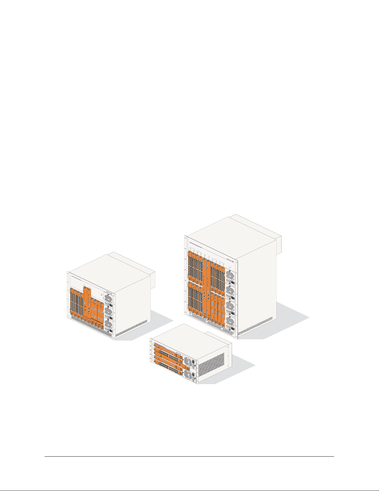
OmniSwitch 9000 switches offer high performance 10/100/1000 Ethernet, Gigabit Ethernet, and 10 Gigabit Ethernet capabilities, as well as embedded server load balancing for enterprise requirements. In this
release, these switches come in three chassis configurations—the 18-slot OmniSwitch 9800 (OS9800), the
10-slot OmniSwitch 9700 (OS9700), and the 5-slot OmniSwitch 9600 (OS9600).
Full duplex is supported on Gigabit Ethernet ports and 10-gigabit Ethernet ports.
Refer to the sections below for additional details on OS9000 switches.
OmniSwitch 9000 Series
The 18-slot OS9800 offers up to 768 Gigabit Ethernet ports and up to ninety-six 10-Gigabit Ethernet
ports.The 10-slot OS9700 offers up to 384 Gigabit Ethernet ports and up to fourty-eight10-gigabit Ethernet ports while the 5-slot OS9600 offers up to 192 Gigabit Ethernet ports and up to twenty-four 10-gigabit
Ethernet ports.
OmniSwitch 9700
1
OK1 OK1
OK2
22x20x18x16x14x12x10x8x6x4x
OmniSwitch 9800
1
NI
9
2
10
3
OS9-GNI-C24
11
4
OS9-GNI-C24
12
CMM
OK
1
OK
OS9-GNI-C24
2
A
A B
O
K
1
OK2
1x 3x 5x 7x 9x 11x
OS9-GNI-C24
A B
B
O
OS9800-CMM
K
1
OK2
1x 3x 5x 7x 9x 11x 13x 15x 17x 19x 21x 23x
4x
10x8x6x
13x 15x 17x 19x
14x12x
22x20x18x16x14x12x10x8x6x4x
20x18x16x
21x 23x
22x
OS9-GNI-C24
CMM
A
B
OS9600/OS9700-CMM
NI
2
OS9-GNI-C24
OS9600/OS9700-CMM
3
OS9-GNI-C24
4
OS9-GNI-C24
OK1
OK1
OS9-GNI-C24
OK2
1x 3x 5x 7x 9x 11x 13x 15x 17x 19x 21x 23x
OK1
OK2
1x 3x 5x 7x 9x 11x 13x 15x 17x 19x 21x
OK1
OK2
1x 3x 5x 7x 9x 11x 13x 15x 17x 19x 21x
22x20x18x16x14x12x10x8x6x4x
22x20x18x16x14x12x10x8x6x4x
23x
22x20x18x16x14x12x10x8x6x4x
23x
PWR
OK2
PS1
OK1
PS2
PS3
OK2
CON
TROL
5
FABRIC
CON
TROL
NI
6
TEMP
OS9-XNI-U2
FAB
1x 3x 5x 7x 9x 11x 13x 15x 17x 19x 21x
RIC
FAN
7
OS9-XNI-U2
T
EMP
PSU
FAN
8
AC
OS9-XNI-U2
USB
COSOLE/MDM
ETHERNET
LINK
ACT
23x
OK
OK1
DC OK
PSU
OVER
OK2
TEMP
OS9-XNI-U2
USB
OK1
100/115/250V
50/60Hz, 8.0/7.0/3.5 A
OK2
LINK/AC
OK1
T
OK2
LINK/ACT
OK1
CONSOLE/MDM
OK2
LINK/ACT
1
LINK/ACT
1
ETHERNET
1
1
LINK/ACT
LINK
LINK/ACT
ACT
AC
OK
2
DC OK
LINK/ACT
OVER
TEMP
2
LI
NK/ACT
100/115/250V
50/60Hz, 8.0/7.0/3.5 A
2
2
AC
OK
DC OK
OVER
T
EMP
100/115/250V
50/60Hz, 8.0/7.0/3.5 A
OmniSwitch 9600
OS9-XNI-U2
1
NI
OS9-GNI-C24
2
LINK/ACT
OS9600/OS9700-CMM
CMM
LINK/ACT
OS9-XNI-U2
3
CONTROL
FABRIC
NI
TEMP
FAN
PSU
OS9-GNI-C24
4
LINK/ACT
LINK/ACT
OK1
OK2
A B
OK1
OK2
1x 3x 5x 7x 9x 11x 13x 15x 17x 19x 21x 23x
4x
10x8x6x
14x12x
20x18x16x14x12x10x8x6x4x
22x
22x20x18x16x
USB
COSOLE/MODEM
ETHERNET
LINK/ACT
5
A B
OK1
13
NI
OS9800-CMM
OK2
1x 3x 5x 7x 9x 11x 13x 15x 17x 19x 21x 23x
4x
10x8x6x
14x12x
22x20x18x16x
OS9-GNI-C24
A B
OK1
OK2
1x 3x 5x 7x 9x 11x
4x
10x8x6x
13x 15x 17x 19x
14x12x
21x 23x
22x20x18x16x
6
A B
14
1x 3x 5x 7x 9x 11x 13x 15x 17x 19x 21x 23x
4x
10x8x6x
14x12x
22x20x18x16x
OS9-GNI-C24
A B
OK
1
OK2
1x 3x 5x 7x 9x 11x
4x
10x8x6x
13x 15x 17x 19x
14x12x
21x 23x
22x20x18x16x
7
15
8
16
O
K
1
PWR
O
K2
A B
PS1
OK1
PS2
OK2
1x 3x 5x 7x 9x 11x
PS3
A B
PS4
OK1
O
1x 3x 5x 7x 9x 11x 13x 15x 17x 19x 21x 23x
K
2
4x
A B
O
K
1
OK2
1x 3x 5x 7x 9x 11x 13x 15x 17x 19x 21x 23x
4x
A B
1x 3x 5x 7x 9x 11x 13x 15x 17x 19x 21x 23x
4x
10x8x6x
10x8x6x
OK1
OK2
10x8x6x
13x 15x 17x 19x
14x12x
OK1
AC
O
K
DC OK
OK2
CONTROL
FABRIC
TEMP
FAN
PSU
OS9-GNI-C24
U
S
B
CONSOLE/MODEM
A B
1x 3x 5x 7x 9x 11x
ETHERNET
LINK/ACT
13x 15x 17x 19x
21x 23x
OVER
TEMP
14x12x
100/
50
1
/6
15/25
CONTROL
FABRIC
TEMP
FAN
PSU
U
S
B
CONSOLE/MODEM
ETHERNET
LINK/ACT
0H
z,
8.
0
14x12x
V
0
/7.0/3.5
22x20x18x16x14x12x10x8x6x4x
A
20x18x16x
21x 23x
22x
22x20x18x16x
22x20x18x16x
OS9-XNI-U2OS9-GNI-C24
AC
O
K
D
C
O
K
O
V
ER
TEMP
OS9-XNI-U2OS9-GNI-C24
O
K1
100/115
50/
60
H
/
2
z
50V
,
8
OK
.
0/
OS9-XNI-U2OS9-GNI-C24
2
7
.0
/
3
.
5
A
OK1
OK2
OS9-XNI-U2OS9-GNI-C24
AC
OK
T
1
L
IN
O
K2
K
A
OK1
C
1
T
LINK
OK
2
TX
AC
1
T
LINK
R
X
TX
ACT
1
L
I
NK
RX
TX
1
R
ACT
X
TX
LI
N
K
AC
R
ACT
X
2
OK
DC OK
LI
N
K
OVER
TX
TEMP
AC
2
T
LINK
100/
RX
50/60Hz, 8.0
1
T
X
1
5/
2
50V
/
7
ACT
.0
/
2
3
.5
A
L
I
NK
RX
TX
2
R
X
T
X
RX
AC
OK
DC OK
O
VER
TEMP
1
0
5
0/115/250V
0
/
6
0H
z,
8.
0/7
.0/
3
.
5
A
OmniSwitch OS9600, OS9700, OS9800
OmniSwitch 9000 Series Hardware Users Guide June 2007 page 1-1
Page 16
Application Example OmniSwitch 9000 Series
s
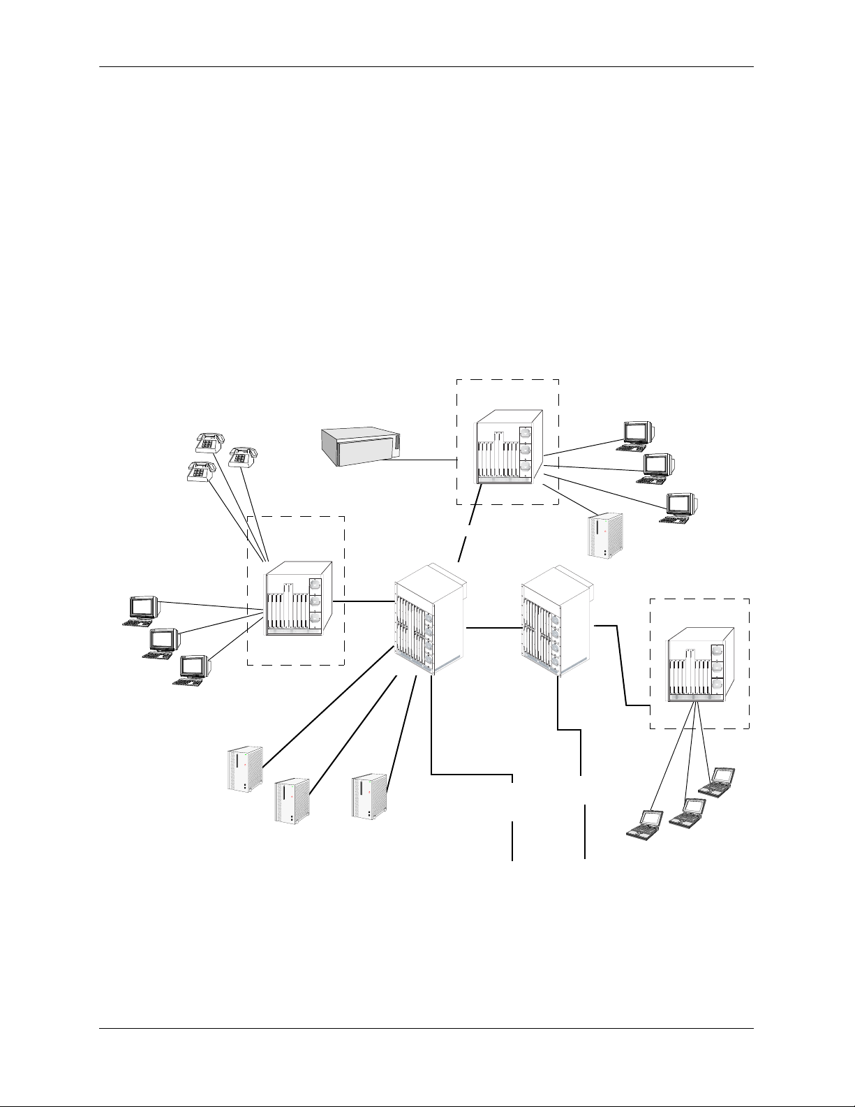
Application Example
The following application example shows one of the many ways OmniSwitch 9000 switches can be used
in an Enterprise network setting:
• Core Switch. In this example, an OS9800 is used as the core switch. Because the example network has
a high-speed Gigabit Ethernet or 10-gigabit Ethernet backbone, the Network Interface (NI) cards in the
chassis will be comprised mainly of Gigabit Ethernet or 10-gigabit Ethernet Network Interface (GNI,
XNI) modules. The core switch connects to wiring closet switches as well as the company server farm.
• Wiring Closet Switches. The switches in wiring closets 1, 2, and 3 must contain some GNI/XNI
modules in order to link to the Gigabit Ethernet/10-gigabit Ethernet core switch. However, in most
cases, these switches will largely be comprised of Gigabit Ethernet Network Interface (GNI) modules.
GNI modules support either 10/100/1000 (copper) or 100/1000 (fiber) Gigabit Ethernet connections.
These Ethernet ports connect to various network devices, such as workstations, IP phones, and servers.
Wiring Closet 2
IP Phones
10/100
OmniPCX
100BaseTX
Data
Wor ks ta ti on s
10/100
Data
Workstations
10/100
WebVi ew
Wiring Closet 1
Email
Server Farm
Oracle
Gigabit/
10-gigabit
Gigabit
OmniVista
Gigabit/10-gigabit
10-gigabit
Core
Switch
Gigabit
Gigabit
Ethernet
Ethernet
Backbone
Backbone
Server
Gigabit/10-gigabit
Gigabit
Gigabit
Ethernet
Ethernet
Backbone
Backbone
10/100
Web Vie w
Wiring Closet 3
Data
Workstation
page 1-2 OmniSwitch 9000 Series Hardware Users Guide June 2007
Page 17

OmniSwitch 9000 Series Availability Features
Availability Features
The switch provides a broad variety of Availability features. Availability features are hardware and
software-based safeguards that help prevent the loss of data flow in the unlikely event of a subsystem failure. In addition, some Availability features allow you to maintain or replace hardware components without powering off your switch or interrupting switch operations. Combined, these features provide added
resiliency and help ensure that your switch is consistently available for your day-to-day network operations.
Hardware-related Availability features include:
• Hardware Redundancy
• Smart Continuous Switching
• Software Rollback
• Hot Swapping
• Hardware Monitoring
• Power Checking Sequence
Information on software-related availability is provided in the OmniSwitch 6800/9000 Switch Management Guide and the OmniSwitch 6800/9000 Network Configuration Guide. Refer to the corresponding
feature chapter (e.g., VRRP).
Hardware Redundancy
Hardware redundancy refers to backup hardware components. If primary hardware components fail or go
offline for any reason, the redundant hardware automatically assumes the primary hardware functions (this
is also referred to as failover). The following components offer redundancy:
• Chassis Management Modules (CMMs)
• Power Supplies
• Fan Units
• MAC EEPROM
Note. Redundancy is a key Availability feature; it is recommended that you install redundant hardware
components in your switch whenever possible. However, CMM redundancy is not supported on the
OS9600 switch because it contains only one CMM slot.
For detailed information on CMM redundancy, refer to Chapter 4, “Chassis Management Module
(CMM).” For information on power supply and fan redundancy, refer to Chapter 2, “Chassis and Power
Supplies.”
OmniSwitch 9000 Series Hardware Users Guide June 2007 page 1-3
Page 18

Availability Features OmniSwitch 9000 Series
Smart Continuous Switching
In redundant CMM configurations, the switch provides support for NIs during failover. In other words, if
the primary CMM fails or goes offline for any reason, NI modules will continue data transmission and
routing functions during the secondary CMM’s takeover process. This Availability feature is referred to as
Smart Continuous Switching.
Incoming Layer 2 packets will continue to be sent to the appropriate egress port during failover. Known
routes will also be supported. (Note, however, that the NI cannot learn new routes without CMM support.
Any new route information will be ignored.) Spanning Tree will continue handling BPDUs received on the
switch ports, as well as port link up and down states. The Spanning Tree topology will not be disrupted.
Note. Smart Continuous Switching is designed to maintain data flow only during CMM failover and is not
intended to support long-term data flow. If both the primary and secondary CMM modules go offline or
are removed from the chassis, switch operations (including all NI support) will be disabled. However,
smart continuous switching is not possible on the OS9600 switch because it contains only one CMM slot.
For more information on CMM redundancy and the failover process, refer to Chapter 4, “Chassis Manage-
ment Module (CMM).”
Software Rollback
Software rollback (also referred to as image rollback) essentially allows the switch to return to a prior “last
known good” version of software in the event of a system software problem. The CMM controls software
rollback through its resilient directory structure design (i.e., /flash/working and /flash/certified).
For detailed information on the software rollback feature, as well as the switch’s /flash/working and
/flash/certified directories, refer to the “Managing CMM Directory Contents” chapter in the Switch
Management Guide.
page 1-4 OmniSwitch 9000 Series Hardware Users Guide June 2007
Page 19

OmniSwitch 9000 Series Availability Features
Hot Swapping
Hot swapping refers to the action of adding, removing, or replacing certain hardware components without
powering off your switch and disrupting other components in the chassis. This feature greatly facilitates
hardware upgrades and maintenance and also allows you to easily replace components in the unlikely
event of hardware failure. The following hardware components can be hot swapped:
• Chassis Management Modules (CMMs)
• Gigabit Ethernet Network Interface modules (GNIs)
• 10-gigabit Ethernet Network Interface modules (XNIs)
• Power supplies
• Fan tray
Hot Swapping Non-Redundant Management Modules and Power Supplies. If there is only one CMM
or power supply installed in the chassis and either of these components is removed or replaced, all switch
functions will stop until a replacement is installed. However, hot swapping is not possible on the OS9600
switch because it contains only one CMM slot.
Hot Swapping NI Modules. It is recommended that you hot swap NIs of the same type
(e.g., OS9-GNI-C24) whenever possible. Otherwise, the network configuration may be adversely affected.
For information on hot swapping CMMs, refer to Chapter 4, “Chassis Management Module (CMM).”
For information on hot swapping NI modules, refer to Chapter 5, “Network Interface (NI) Modules.”
For information on hot swapping power supplies and the fan tray, refer to Chapter 2, “Chassis and Power
Supplies.”
Hardware Monitoring
Automatic Monitoring
Automatic monitoring refers to the switch’s built-in sensors that automatically monitor operations. The
majority of automatic monitoring is provided by the CMM. If an error is detected (e.g., over-threshold
temperature), the CMM immediately sends a trap to the user. The trap is displayed on the console in the
form of a text error message. (In the case of an over-threshold temperature condition, the CMM displays
an amber TEMP LED in addition to sending a trap.)
LEDs
LEDs, which provide visual status information, are provided on the CMM, NI, and power supply front
panels. LEDs are used to indicate conditions, such as hardware and software status, temperature errors,
link integrity, data flow, etc. For detailed LED descriptions, refer to the corresponding hardware component chapter (e.g., “Network Interface (NI) Modules”).
User-Driven Monitoring
User-driven hardware monitoring refers to CLI commands that are entered by the user in order to access
the current status of hardware components. The user enters “show” commands that output information to
the console. The Show commands for all the features are described in detail in the OmniSwitch CLI Refer-
ence Guide.
OmniSwitch 9000 Series Hardware Users Guide June 2007 page 1-5
Page 20

Availability Features OmniSwitch 9000 Series
Power Checking Sequence
The power checking sequence is another built-in Availability feature. This feature helps regulate power in
the switch whenever the switch is booted or an NI module is installed in the chassis.
The sequence is a joint effort between the CMM, the NI modules, and the power supplies. During the boot
sequence, the primary CMM automatically compares the power consumption required by installed NIs
with the power available from the power supplies. If there is not adequate power to support all NIs, the
CMM will power on only the supported number of NIs, starting from the first NI slot position.
Important. During the power checking sequence, CMMs receive priority and are always powered on. NI
modules are then powered on sequentially by slot position. In other words, the NI in slot 1 is powered on,
then slot 2, then slot 3, etc. For information on slot positions, refer to Chapter 2, “Chassis and Power
Supplies.”
Installing a New NI into a Running Chassis
When an NI module is installed in the chassis, only a small portion of the circuitry is initially powered up.
The CMM immediately reads the incoming module’s ID and determines how much power the module will
require. If the number of power supplies installed in the chassis can provide sufficient power, the CMM
turns on the incoming module. If the number of installed power supplies cannot provide sufficient power,
the incoming NI will remain powered off.
page 1-6 OmniSwitch 9000 Series Hardware Users Guide June 2007
Page 21
2 Chassis and Power
Supplies
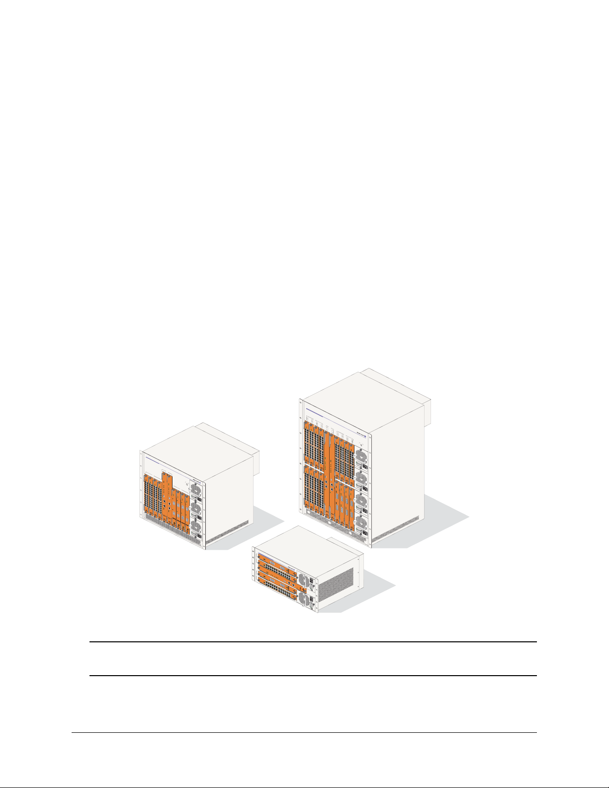
The OmniSwitch 9000 switches are available in three chassis configurations—the 18-slot OmniSwitch
9800 (OS9800), the 10-slot OmniSwitch 9700 (OS9700), and the 5-slot OmniSwitch 9600 (OS9600). This
chapter includes detailed information on each of these chassis types. The topics include:
• Technical specifications on page 2-7.
• Switch mounting information on page 2-12.
• Power supplies and power supply redundancy on page 2-16.
• Temperature management on page 2-33.
• Chassis fan tray on page 2-35.
• Monitoring the chassis components via the Command Line Interface (CLI) on page 2-21.
OmniSwitch 9800
1
NI
9
2
10
3
OS9-GNI-C24
11
4
OS9-GNI-C24
12
CMM
O
K1
O
OS9-GNI-C24
K
2
A
A B
O
K1
OK2
1x 3x 5x 7x 9x 11x
OS9-GNI-C24
A B
B
OK1
OS9800-CMM
OK2
1x 3x 5x 7x 9x 11x 13x 15x 17x 19x 21x 23x
5
4x
A B
OK1
13
NI
OS9800-CMM
O
1x 3x 5x 7x 9x 11x 13x 15x 17x 19x 21x 23x
6
K
4x
2
A B
14
1x 3x 5x 7x 9x 11x 13x 15x 17x 19x 21x 23x
7
4x
15
8
16
OK1
PWR
OK2
A B
10x8x6x
14x12x
O
K
1
O
22x20x18x16x
K
2
CONTROL
FABRIC
TEMP
FAN
PSU
OS9-GNI-C24
OS9-GNI-C24
U
S
B
U
A B
O
K
1
CONSOLE/MODEM
O
1x 3x 5x 7x 9x 11x
K2
A B
CONSOLE/MODEM
1x 3x 5x 7x 9x 11x
4x
ETHERNET
ETHERNET
10x8x6x
LINK/ACT
13x 15x 17x 19x
14x12x
13x 15x 17x 19x
21x 23x
22x20x18x16x
21x 23x
PS1
OK1
PS2
O
1x 3x 5x 7x 9x 11x
K2
PS3
A B
PS4
O
K1
OK2
1x 3x 5x 7x 9x 11x 13x 15x 17x 19x 21x 23x
4x
A B
OK1
O
1x 3x 5x 7x 9x 11x 13x 15x 17x 19x 21x 23x
K2
4x
A B
1x 3x 5x 7x 9x 11x 13x 15x 17x 19x 21x 23x
4x
10x8x6x
10x8x6x
10x8x6x
13x 15x 17x 19x
14x12x
OK1
AC
OK
D
C
OK
OK
2
O
V
ER
TEMP
14x12x
100/115/2
5
0
/6
0H
CONTROL
z
5
,
0V
8.
14x12x
0/7.
0/
3
.5
A
FABRIC
22x20x18x16x14x12x10x8x6x4x
20x18x16x
21x 23x
TEMP
22x
FAN
22x20x18x16x
PSU
22x20x18x16x
S
B
OS9-XNI-U2OS9-GNI-C24
AC
OK
DC OK
OVER
T
EM
P
OS9-XNI-U2OS9-GNI-C24
OK1
100/
50/
115/
6
0H
2
z
5
,
8.0
0V
O
K
OS9-XNI-U2OS9-GNI-C24
/
2
7.
0
/
3.
5
A
O
K1
OK2
OS9-XNI-U2OS9-GNI-C24
ACT
OK1
LI
OK2
N
K
LIN
K/ACT
A
OK1
CT
1
LINK
OK2
TX
ACT
1
LIN
K
RX
TX
ACT
1
LINK
RX
TX
1
R
ACT
X
T
X
LINK
AC
R
A
X
CT
2
OK
D
C
LIN
OK
K
O
V
T
E
X
R
TEMP
ACT
2
LI
NK
100/
RX
50/60
11
TX
5/
H
25
z, 8.0/7.0/3.5
0V
ACT
2
A
LINK
RX
TX
2
R
X
T
X
R
X
AC
O
K
DC
O
K
O
V
ER
TEMP
100/
5
0
115
/6
0
Hz,
/2
5
0
8.
V
0
/
7.
0/
3
.5
A
OmniSwitch 9700
1
OK1OK1
OK2
22x20x18x16x14x12x10x8x6x4x
10x8x6x
10x8x6x
13x 15x 17x 19x
14x12x
14x12x
22x20x18x16x14x12x10x8x6x4x
20x18x16x
21x 23x
22x
22x20x18x16x
OS9-GNI-C24
OS9-GNI-C24
O
CMM
A
B
OS9600/OS9700-CMM
NI
2
OS9-GNI-C24
OS9600/OS9700-CMM
3
OS9-GNI-C24
4
OS9-GNI-C24
OK1
O
K
1
OK2
1x 3x 5x 7x 9x 11x 13x 15x 17x 19x 21x 23x
OK1
OK
1x 3x 5x 7x 9x 11x 13x 15x 17x 19x 21x
2
22x20x18x16x14x12x10x8x6x4x
22x20x18x16x14x12x10x8x6x4x
23x
PWR
OS9-GNI-C24
OK2
PS1
OK1
PS2
PS3
OK2
CON
TROL
OK1
5
FABRIC
O
1x 3x 5x 7x 9x 11x 13x 15x 17x 19x 21x
K
2
CON
TROL
NI
6
TEMP
OS9-XNI-U2
FAB
1x 3x 5x 7x 9x 11x 13x 15x 17x 19x 21x
RIC
FAN
7
OS9-XNI-U2
TEMP
PSU
FAN
8
AC
OS9-XNI-U2
OK
USB
OK1
DC OK
PSU
OVER
OK2
TEMP
OS9-XNI-U2
USB
OK1
100/115/250V
5
0
/
OK
6
0Hz, 8
2
.0
/7.0/3.5
L
I
COSOLE/MD
M
ETHERNET
LINK
22x20x18x16x14x12x10x8x6x4x
ACT
23x
23x
A
OK1
NK/ACT
OK
2
LINK/ACT
O
CONSOLE/
K1
OK2
MDM
L
I
NK/AC
1
T
L
INK
1
/
A
C
T
ETHERNET
1
1
LINK
/
ACT
LINK
LI
ACT
NK/A
C
T
AC
OK
2
DC OK
LI
N
K/ACT
OVER
TEMP
2
LINK/ACT
1
00/115
50
/
60H
/
250V
z
,
8.0
/
7
.0
/3.
2
5
A
2
AC
OK
DC OK
OVER
TEMP
10
50/60Hz, 8.0/7.0/3.5 A
0
/115/2
5
0V
OmniSwitch 9600
OS9-XNI-U2
1
NI
OS9-GNI-C24
2
LINK/ACT
OS9600/OS9700-CMM
CMM
OS9-XNI-U2
3
CONTROL
FABRIC
NI
TEMP
OS9-GNI-C24
4
LINK/ACT
K1
OK2
A B
OK1
O
1x 3x 5x 7x 9x 11x 13x 15x 17x 19x 21x 23x
K
2
A B
OK1
OK2
1x 3x 5x 7x 9x 11x
4x
4x
10x8x6x
10x8x6x
14x12x
13x 15x 17x 19x
14x12x
20x18x16x14x12x10x8x6x4x
22x
22x20x18x16x
21x 23x
22x20x18x16x
LINK/ACT
FAN
PSU
USB
COSOLE/MODEM
LINK/ACT
ETHERNET
LINK/ACT
OmniSwitch OS9600, OS9700, OS9800
Warning. Do NOT install white color OmniSwitch 7700/7800 CMMs or NI modules in an OmniSwitch
9000 Series chassis, or damage to the modules or chassis may occur.
OmniSwitch 9000 Series Hardware Users Guide June 2007 page 2-1
Page 22
OmniSwitch 9800 Chassis and Power Supplies
OmniSwitch 9800
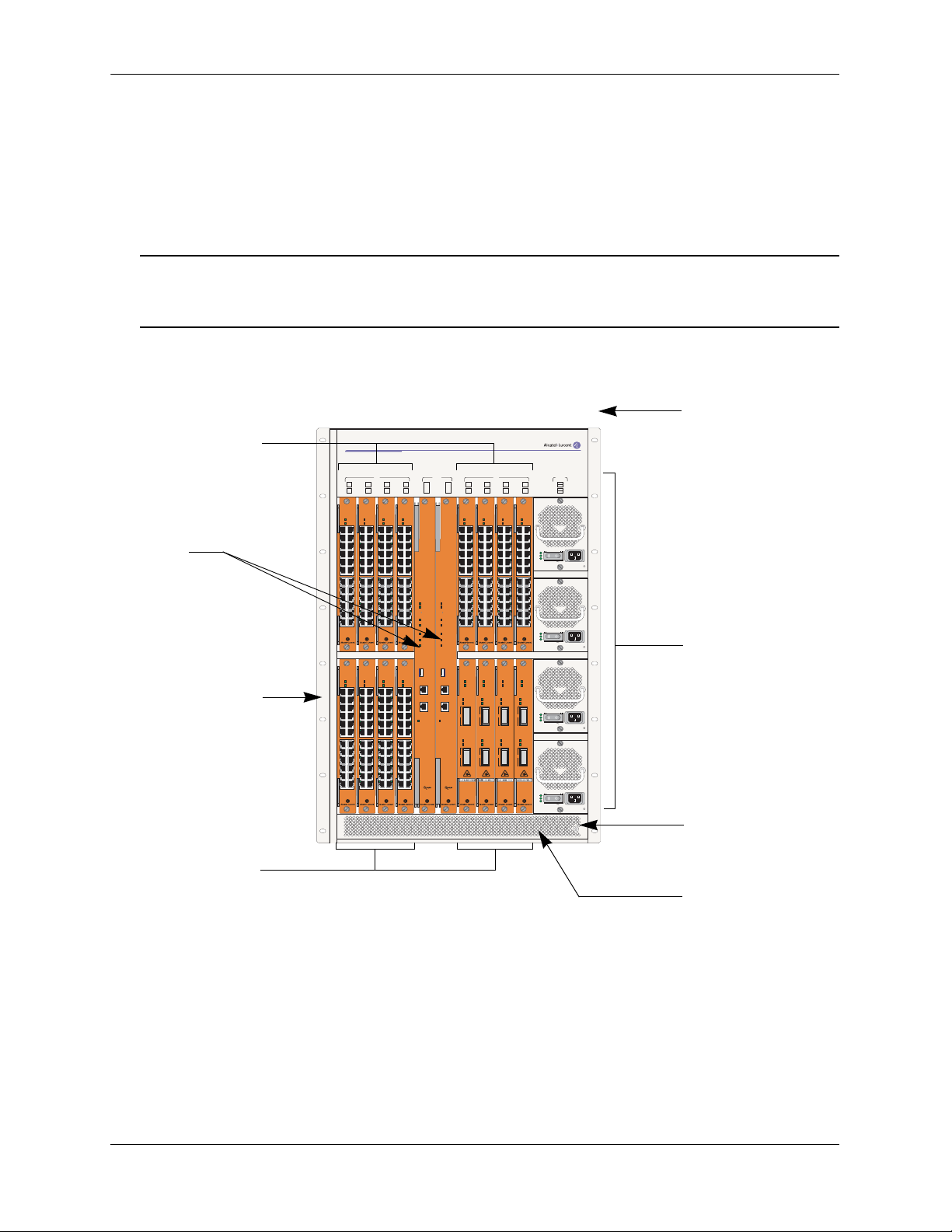
The OmniSwitch 9800 is a high performance switch offering 16 slots for Gigabit Ethernet and/or 10-Gigabit Ethernet Network Interface (NI) modules. An additional two slots are reserved for primary and redundant Chassis Management Modules (CMMs). The OmniSwitch 9800 supports a maximum of four power
supplies.
Note. Power supply requirements are based on the number of NIs installed in the chassis. Refer to
“Power Supplies” on page 2-16 for important information on power supplies and power supply
redundancy.
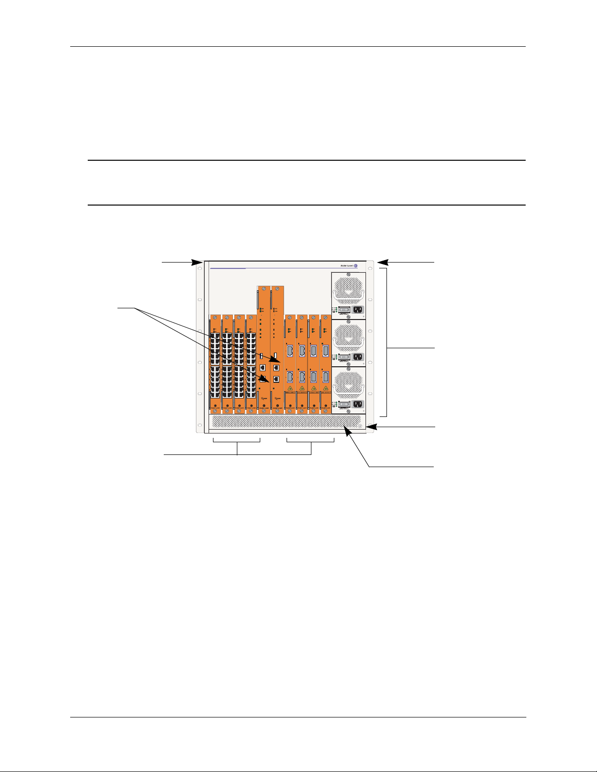
The following illustrations outline the major components of the OmniSwitch 9800 switch.
Front Rack Mount
Network Interface
(NI) Modules
CMMs
Front Rack Mount
Flange
OmniSwitch 9800
1 2 3 4
9 10 11 12
OS9-GNI-C24
OS9-GNI-C24
OK1
OK1
OK2
OK2
1x 3x 5x
1x 3x 5x
6x4x
6x4x
7x 9x 11x
7x 9x 11x
12x10x8x
12x10x8x
13x 15x 17x 19x 21x 23x
13x 15x 17x 19x 21x 23x
22x20x18x16x14x
22x20x18x16x14x
OS9-GNI-C24
OS9-GNI-C24
OK1
OK1
OK2
OK2
1x 3x 5x 7x 9x 11x 13x 15x 17x 19x 21x 23x
1x 3x 5x 7x 9x 11x 13x 15x 17x 19x 21x 23x
22x20x18x16x14x12x10x8x6x4x
22x20x18x16x14x12x10x8x6x4x
NI
6x4x
12x10x8x
22x20x18x16x14x
22x20x18x16x14x12x10x8x6x4x
OK1
OK2
OK1
OK2
OS9-GNI-C24
1x 3x 5x
7x 9x 11x
13x 15x 17x 19x 21x 23x
OS9-GNI-C24
1x 3x 5x 7x 9x 11x 13x 15x 17x 19x 21x 23x
6x4x
12x10x8x
22x20x18x16x14x
22x20x18x16x14x12x10x8x6x4x
OS9-GNI-C24
OK1
OK2
1x 3x 5x
7x 9x 11x
13x 15x 17x 19x 21x 23x
OS9-GNI-C24
OK1
OK2
1x 3x 5x 7x 9x 11x 13x 15x 17x 19x 21x 23x
A B
OS9800-CMM
OK1
OK2
CONTROL
FABRIC
TEMP
FAN
PSU
USB
CONSOLE/MODEM CONSOLE/MODEM
ETHERNET
LINK/ACT
OK1
OK2
CONTROL
FABRIC
TEMP
FAN
PSU
USB
ETHERNET
LINK/ACT
5 6 7 8
13 14 15 16
OS9800-CMM
OS9-GNI-C24
OK1
OK2
1x 3x 5x 7x 9x 11x 13x 15x 17x 19x 21x 23x
22x20x18x16x14x12x10x8x6x4x
22x20x18x16x14x12x10x8x6x4x
OS9-XNI-U2
OK1
OK2
ACT
LINK
RX
1
1
TX
ACT
LINK
RX
2
2
TX
NICMM PWR
OS9-GNI-C24
OS9-GNI-C24
OS9-GNI-C24
OK1
OK1
OK1
OK2
OK2
OK2
1x 3x 5x 7x 9x 11x 13x 15x 17x 19x 21x 23x
1x 3x 5x 7x 9x 11x 13x 15x 17x 19x 21x 23x
22x20x18x16x14x12x10x8x6x4x
22x20x18x16x14x12x10x8x6x4x
OS9-XNI-U2
OS9-XNI-U2
OS9-XNI-U2
OK1
OK1
OK1
OK2
OK2
OK2
ACT
ACT
ACT
LINK
LINK
LINK
RX
RX
RX
1
1
TX
TX
TX
ACT
ACT
ACT
LINK
LINK
LINK
RX
RX
RX
2
2
TX
TX
TX
PS1
PS2
PS3
PS4
1x 3x 5x 7x 9x 11x 13x 15x 17x 19x 21x 23x
AC OK
DC OK
OVER
TEMP
100/115/250V
50/60Hz, 8.0/7.0/3.5 A
AC OK
DC OK
OVER
TEMP
100/115/250V
50/60Hz, 8.0/7.0/3.5 A
AC OK
DC OK
OVER
TEMP
100/115/250V
50/60Hz, 8.0/7.0/3.5 A
AC OK
DC OK
OVER
TEMP
100/115/250V
50/60Hz, 8.0/7.0/3.5 A
Flange
Power Supplies
Grounding Lug
Network Interface
(NI) Modules
Air Intake Vent
OmniSwitch 9800 Front View
page 2-2 OmniSwitch 9000 Series Hardware Users Guide June 2007
Page 23
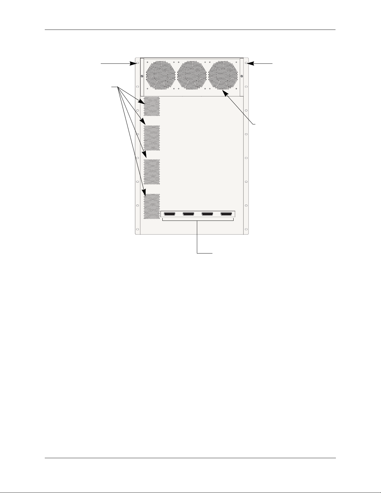
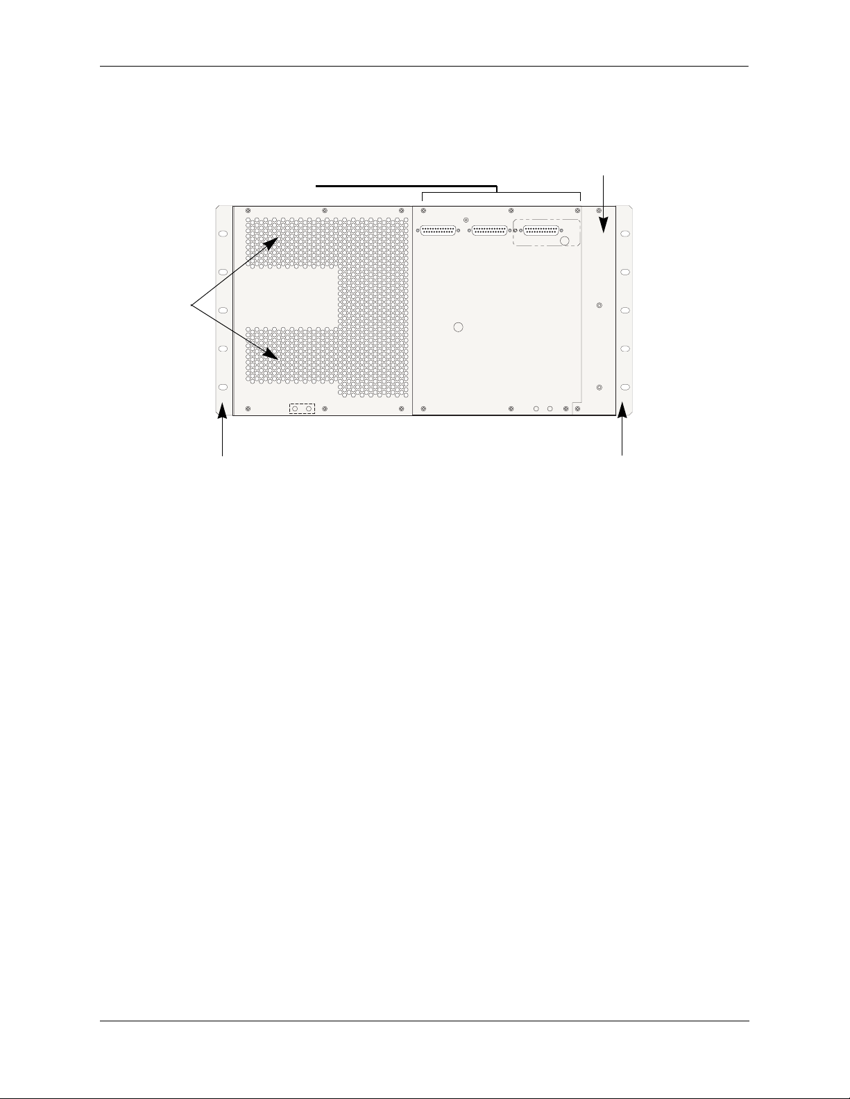
Chassis and Power Supplies OmniSwitch 9800
Front Rack Mount
Flange
Airflow Exhaust Vents
(for power supplies)
Front Rack Mount
Flange
Fan Tray (contains three fans)
for chassis temperature
control and airflow exhaust
Connectors for inline power supply.
OmniSwitch 9800 Back View
OmniSwitch 9000 Series Hardware Users Guide June 2007 page 2-3
Page 24

OmniSwitch 9800 Chassis and Power Supplies
OmniSwitch 9800 Technical Specifications
Total 10/100/1000 copper Ethernet ports available
768 (Fully-populated with OS9-GNI-C48T modules. No other
NI module types installed.)
384 (Fully-populated with OS9-GNI-C24 and/or OS9-GNI-P24
modules. No other NI module types installed.)
Total 1000BaseSX Ethernet
ports available
Total 10-Gigabit Ethernet ports
available
384 (Fully-populated with OS9-GNI-U24 modules. No other
NI module types installed.)
32 (Fully-populated with OS9-XNI-U2 modules, with each
XNI containing two GBICs. No other NI modules installed.)
96 (Fully-populated with OS9-XNI-U6 modules, with each
XNI containing six GBICs. No other NI modules installed.)
Total slots available for network
16
interface (NI) modules
Total slots available for CMMs 2
Total bays for power supplies 4
Power 85 watts (approximate)
OmniSwitch 9800 Chassis Dimensions
Overall Width (including rack-mount flanges) 19 1/8 inches
Chassis Width (rack-mount flanges not included) 17 9/16 inches
Height 29 3/4 inches
Height (rack units) 17 RU
Overall Depth (including required fan tray) 17 5/16 inches
Chassis Depth (fan tray not included) 14 3/4 inches
page 2-4 OmniSwitch 9000 Series Hardware Users Guide June 2007
Page 25
Chassis and Power Supplies OmniSwitch 9700
OmniSwitch 9700
The OmniSwitch 9700 is a high performance switch offering eight slots for Gigabit Ethernet and/or 10gigabit Ethernet Network Interface (NI) modules. Additional two slots are reserved for primary and redundant Chassis Management Modules (CMMs). The OmniSwitch 9700 supports a maximum of three power
supplies.
Note. Power supply requirements are based on the number of NIs installed in the chassis. Refer to
“Power Supplies” on page 2-16 for important information on power supplies and power supply redun-
dancy.
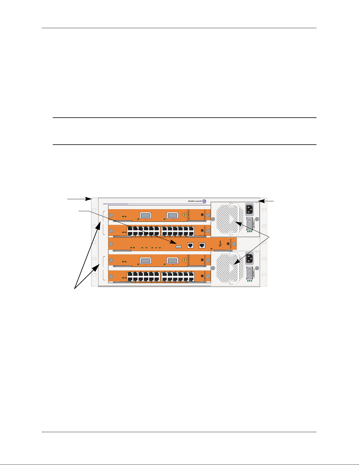
The following illustrations outline the major components of the OmniSwitch 9700 switch.
Front Rack Mount
CMMs
Network Interface
(NI) Modules
OmniSwitch 9700
OS9600/OS9700-CMM
OS9600/OS9700-CMM
OS9-GNI-C24
OS9-GNI-C24
OS9-GNI-C24
OS9-GNI-C24
COSOLE/MODEM
CONTROL
FABRIC
TEMP
FAN
PSU
USB
ETHERNET
LINK/ACT
CONTROL
FABRIC
TEMP
FAN
PSU
LINK/ACT LINK/ACT LINK/ACT LINK/ACT
USB
COSOLE/MODEM
LINK/ACT LINK/ACT LINK/ACT LINK/ACT
ETHERNET
LINK/ACT
OS9-XNI-U2
OS9-XNI-U2
OmniSwitch 9700 Front View
OS9-XNI-U2
Front Rack Mount
FlangeFlange
OS9-XNI-U2
Power Supplies
Grounding Lug
Air Intake Vent
OmniSwitch 9000 Series Hardware Users Guide June 2007 page 2-5
Page 26
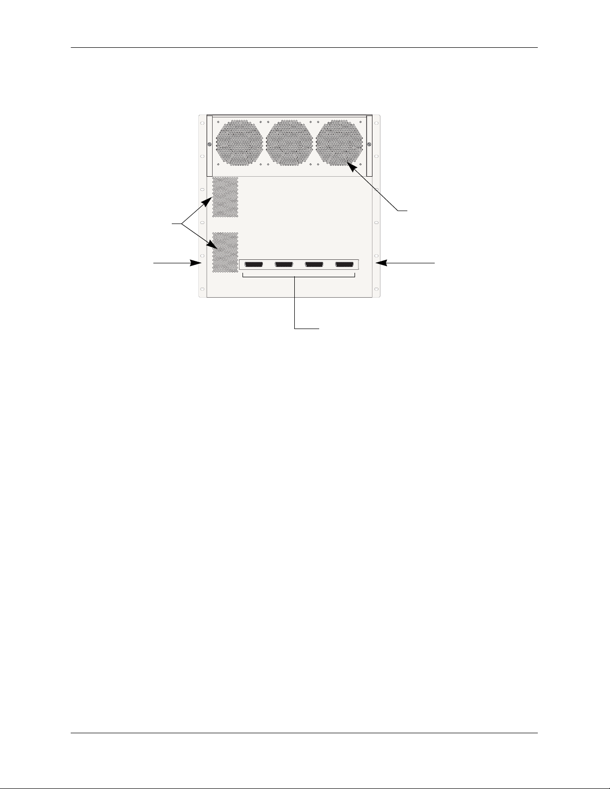
OmniSwitch 9700 Chassis and Power Supplies
Fan Tray (contains three fans)
Airflow Exhaust Vents
(for power supplies)
for chassis temperature
control and airflow exhaust
Front Rack Mount
Flange
Front Rack Mount
Flange
Connectors reserved for use with inline
power supply.
OmniSwitch 9700 Back View
page 2-6 OmniSwitch 9000 Series Hardware Users Guide June 2007
Page 27

Chassis and Power Supplies OmniSwitch 9700
OmniSwitch 9700 Technical Specifications
Total 10/100/1000 copper Ethernet ports available
Total 1000Base SX fiber Ethernet ports available
Total 10-Gigabit Ethernet ports
available
384 (Fully-populated with OS9-GNI-C24 and/or OS9-GNI-P24
modules. No other NI module types installed.)
192 (Fully-populated with OS9-GNI-U24 modules. No other
NI module types installed.)
16 (Fully-populated with OS9-XNI-U2 modules, with each
XNI containing two XFPs. No other NI modules installed.)
48 (Fully-populated with OS9-XNI-U6 modules, with each
XNI containing six XFPs. No other NI modules installed.)
Total slots for network interface
8
(NI) modules
Total slots for CMM 2
Total bays for power supplies 3
Power 50 W (approximate)
OmniSwitch 9700 Chassis Dimensions
Overall Width (including rack-mount flanges) 19 1/8 inches
Chassis Width (rack-mount flanges not included) 17 9/16 inches
Height 19 1/4 inches
Height (rack units) 11 RU
Overall Depth (including required fan tray) 17 5/16 inches
Chassis Depth (fan tray not included) 14 3/4 inches
OmniSwitch 9000 Series Hardware Users Guide June 2007 page 2-7
Page 28
OmniSwitch 9600 Chassis and Power Supplies
OmniSwitch 9600
The OmniSwitch 9600 is a high performance switch offering four slots for Gigabit Ethernet and/or
10 gigabit Ethernet Network Interface (NI) modules. An additional one slot is reserved for the primary
Chassis Management Module (CMM). The OmniSwitch 9600 supports a maximum of two load sharing
power supplies on the front panel and there are optional power connectors, which consist of three DB-25
connectors mounted on the rear panel of the chassis for PoE applications. Either OS9-IP-SHELF or
360W/510W power supplies can be used. The first two connectors support OS9-IP-SHELF power supplies
and the third connector supports 360W/510W power supplies.
Note. Power supply requirements are based on the number of NIs installed in the chassis. Refer to
“Power Supplies” on page 2-16 for important information on power supplies and power supply redun-
dancy.
The following illustrations outline the major components of the OmniSwitch 9600 switch:
Front Rack
Mount
Flange
OmniSwitch 9600
CMM
NI
CMM
NI
Network
Interface (NI) Modules
OS9-XNI-U2
1
OS9-GNI-C24
2
OS9600/OS9700-CMM
OS9-XNI-U2
3
OS9-GNI-C24
4
OK1
OK2
LINK/ACT
OK1
OK2
OK1
OK2
CONTROL
FABRIC
OK1
OK2
LINK/ACT
OK1
OK2
LINK/ACT
TEMP
OVER
AC OK
DC OK
TEMP
FAN
PSU
USB
COSOLE/MODEM
LINK/ACT
ETHERNET
LINK/ACT
TEMP
OVER
AC OK
DC OK
Front RackMount Flange
Power Supplies
OmniSwitch 9600 Front View
page 2-8 OmniSwitch 9000 Series Hardware Users Guide June 2007
Page 29
Chassis and Power Supplies OmniSwitch 9600
Fan Tray (contains four fans)
Connectors reserved for use with inline
power supply.
for chassis temperature
control and airflow exhaust
Airflow
exhaust vents
(for power
supplies)
Front rack mount
flange
Front rack mount flange
OmniSwitch 9600 Back View
OmniSwitch 9000 Series Hardware Users Guide June 2007 page 2-9
Page 30

OmniSwitch 9600 Chassis and Power Supplies
OmniSwitch 9600 Technical Specifications
Total 10/100/1000 copper Ethernet ports available
Total 1000Base SX fiber Ethernet ports available
Total 10-Gigabit Ethernet ports
available
192 (Fully-populated with OS9-GNI-C24 and/or OS9-GNI-P24
modules. No other NI module types installed.)
96 (Fully-populated with OS9-GNI-U24 modules. No other NI
module types installed.)
8 (Fully-populated with OS9-XNI-U2 modules, with each XNI
containing two XFPs. No other NI modules installed.)
24 (Fully-populated with OS9-XNI-U6 modules, with each
XNI containing six XFPs. No other NI modules installed.)
Total slots for network interface
4
(NI) modules
Total slots for CMM 1
Total bays for power supplies 2
Power 50 W (approximate)
OmniSwitch 9600 Chassis Dimensions
Width 19 inches
Height 9.575 inches
Depth 14.432 inches
page 2-10 OmniSwitch 9000 Series Hardware Users Guide June 2007
Page 31

Chassis and Power Supplies Chassis Slot Numbering
Chassis Slot Numbering
The term slot refers to the position at which a CMM or NI module is installed in chassis. CMM slot positions are designated as Slot A and Slot B. On OS9800 switches, NI slot numbers range from 1 to 16. On
OS9700 switches, NI slot numbers range from 1 to 8. On OS9600 switches, NI slot numbers range from 1
to 4.
Note. The OS9600 contains only one CMM slot.
Power supply bays are also given specific slot numbers. On OS9800 switches, power supply slot numbers
are designated PS-1 through PS-4 from top to bottom. On OS9700 switches, power supply slot numbers
are designated PS-1 through PS-3 from top to bottom. On OS9600 switches, power supply slot numbers
are designated PS-1 and PS-2 from top to bottom.
OmniSwitch 9700
OmniSwitch 9800
NI NICMM PWR
1 2 3 4
9 10 11 12
A B
5 6 7 8
13 14 15 16
CMM
AB
NI NI
1234
PS1
PS2
PS3
PS4
5678
PWR
PS-1
PS1
PS2
PS3
PS-2
1
2
10
9
11
4
3
A
B
12
OS9800 (18-Slot Chassis)
5 6
7 8
13 141516
PS-1
PS-2
PS-3
PS-4
1
OmniSwitch 9600
1
NI
2
CMM
3
NI
4
4
2
A B
3
5 6
7 8
OS9700 (10-Slot Chassis)
1
2
A
3
4
OS9600 (5-Slot Chassis)
PS-3
PS-1
PS-2
OmniSwitch 9000 Series Hardware Users Guide June 2007 page 2-11
Page 32

Mounting the Switch Chassis and Power Supplies
Viewing Chassis Slot Information
To view basic slot information via the CLI, enter the show module command at the CLI prompt:
-> show module
To view more detailed slot information, use the show module long form of this command. For example:
-> show module long
Mounting the Switch
Important. Two people are required when lifting the chassis. Due to its weight, lifting the chassis unassisted can cause personal injury. If you need to move the switch, be sure to power it down and remove all
modules and power supplies. For instructions on removing CMM or NI modules, refer to Chapter 5,
“Network Interface (NI) Modules.” For instructions on removing power supplies, refer to “Removing a
Power Supply” on page 2-30.
Note. Due to their weight and airflow requirements, OS9800, OS9700, and OS9600 switches cannot be
wall-mounted.
Airflow Considerations
Be sure that your switch is placed in a well-ventilated, static-free environment. Always allow adequate
clearance at the front and sides of the switch, as well as behind the switch’s fan unit (located at the top-rear
of the chassis). The following top-view diagram shows recommended minimum clearances for adequate
airflow.
Rear. 6 inches minimum
}
at rear of chassis fan
unit.
Sides. 2 inches minimum
at left and right sides.
Front. 6 inches minimum
}
at front of chassis.
Chassis Top View
Note. Never obstruct the air intake vents located at the bottom-front and bottom-sides of the chassis or the
fan unit’s air output vents located at the rear of the chassis. Clearance is not required at the top and bottom
of the chassis.
page 2-12 OmniSwitch 9000 Series Hardware Users Guide June 2007
Page 33

Chassis and Power Supplies Mounting the Switch
Rack-Mounting
Refer to the important guidelines below before installing the OmniSwitch 9800/9700/9600 chassis in a
rack.
• Be sure that all modules and power supplies are removed before rack-mounting the switch. For instruc-
tions on removing CMM or NI modules, refer to Chapter 5, “Network Interface (NI) Modules.” For
instructions on removing power supplies, refer to “Removing a Power Supply” on page 2-30.
• Rack-mounting the chassis requires three people—two people to hold the chassis and position it in the
rack and a third person to secure the chassis to the rack using the attachment screws.
• The chassis has two integral rack-mount flanges that support standard 19-inch rack mount installa-
tions. Refer to page 2-15 for information on optional rack-mounting hardware.
• Alcatel-Lucent does not provide rack-mount screws. Use the screws supplied by the rack vendor.
• To prevent a rack from becoming top heavy, it is recommended that you install the switch at the
bottom of the rack whenever possible.
• If you are installing the switch in a relay rack, be sure to install and secure the rack per the rack manu-
facturer’s specifications.
• Refer to page 2-12 for important chassis airflow recommendations before installing.
To rack-mount the switch, follow the steps below:
1 Mark the holes on the rack where the chassis is to be installed.
2 Using two people, lift and position the chassis until the rack-mount flanges are flush with the rack post.
3 Align the holes in the flanges with the rack holes you marked in step 1.
4 Once the holes are aligned, use a third person to insert a screw through the bottom hole on each flange.
Tighten both screws until they are secure.
OmniSwit ch 9700
CMM
A
1
B
NI
2
3
4
PWR
PS1
PS2
PS3
5
NI
6
7
8
Note. Be sure to install the screws in the bottom hole of each flange, as shown, before proceeding.
OmniSwitch 9000 Series Hardware Users Guide June 2007 page 2-13
Page 34
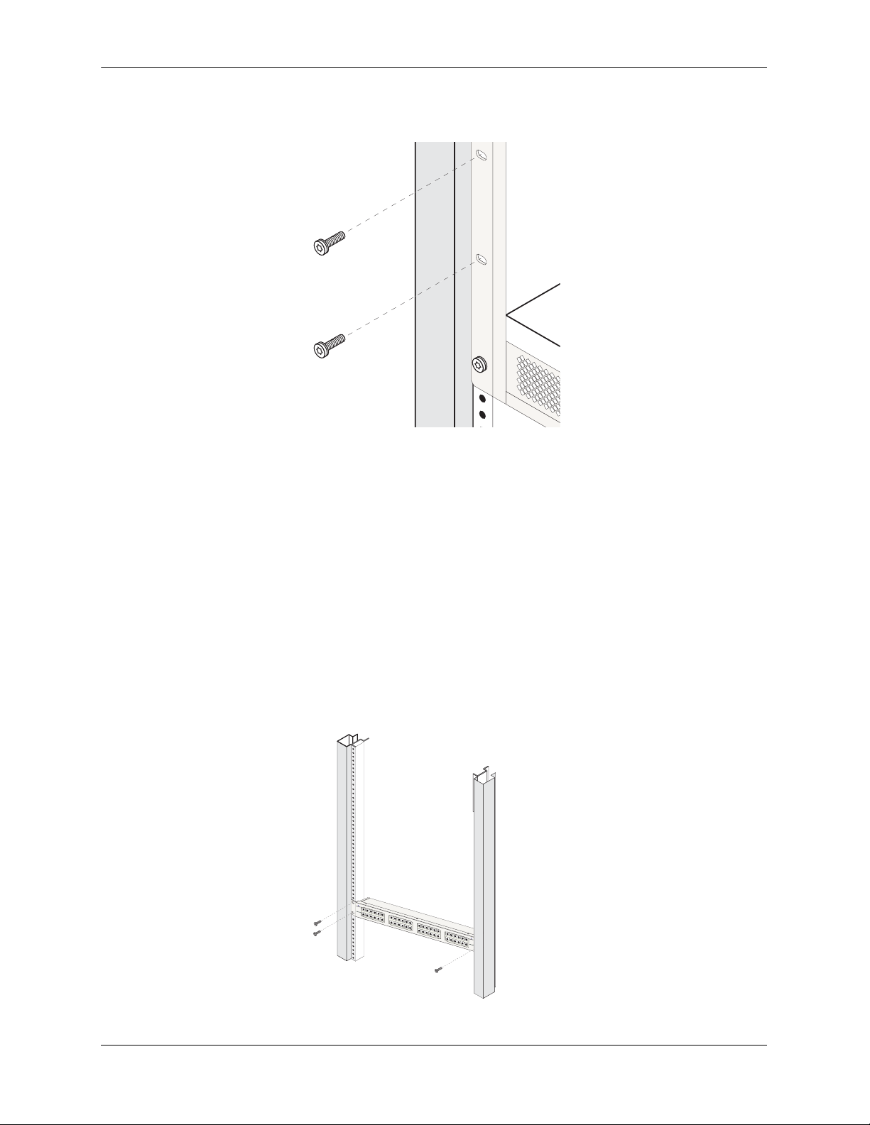
Mounting the Switch Chassis and Power Supplies
5 Once the screws at the bottom of each flange are secure, install the remaining screws. Be sure that all
screws are securely tightened.
To rack-mount the patch panel, follow the steps explained below:
1 Remove all the connections before rack mounting the patch panel.
2 Rack-mounting the patch panel requires two people— one person to hold the patch panel and position
it in the rack and a second person to secure the patch panel to the rack using the attachment screws.
3 Mark the holes on the rack where the patch panel is to be installed.
4 Using one person, lift and position the patch panel until the rack-mount flanges are flush with the rack
post.
5 Align the holes in the flanges with the rack holes you marked in step 3.
6 Once the holes are aligned, use a second person to insert a screw through the bottom hole on each
flange. Tighten both screws until they are secure.
page 2-14 OmniSwitch 9000 Series Hardware Users Guide June 2007
Page 35

Chassis and Power Supplies Mounting the Switch
Optional Rack-Mounting Hardware
All OmniSwitch 9000 switches are shipped with integral front rack-mount flanges. These flanges support
standard 19-inch rack mount installations. If you have non-standard rack-mount requirements,
Alcatel-Lucent offers optional hardware for the following applications:
• 23-inch rack installations
• Side-mount hardware for additional support
For information on this optional rack mounting hardware, contact your Alcatel-Lucent representative.
Standalone
The OmniSwitch 9000 switches can be installed unmounted as a standalone unit. Be sure that the installation location is a stable, flat surface that can accommodate the fully-populated weight of all switches being
installed. One fully-populated OmniSwitch 9800 weighs approximately 188 pounds (85 kilograms), a
OmniSwitch 9700 weighs approximately 128 pounds (58 kilograms); a fully-populated OmniSwitch 9600
weighs approximately 66 pounds (30 kilograms).
Note. OmniSwitch 9000 switches must be installed “right side up”. Never attempt to operate a switch
while it is lying on its side.
To install the switch as a standalone unit, follow the steps below:
1 Use two or more people to move and position the unpopulated chassis upright on the floor or bench
where it is to be installed.
2 Be sure that adequate clearance has been provided for chassis airflow and that you have placed the
chassis within reach of all required AC outlets. For recommended airflow allowances, refer to page 2-12.
Note. For detailed information on installing additional components and connecting the switch, refer to the
OmniSwitch 9000 Getting Started Guide.
OmniSwitch 9000 Series Hardware Users Guide June 2007 page 2-15
Page 36

Power Supplies Chassis and Power Supplies
Power Supplies
The OmniSwitch 9800 supports a total of four power supplies; the OmniSwitch 9700 supports a total of
three power supplies; the OmniSwitch 9600 supports a total of two power supplies (refer to page 2-27 for
important redundancy information). The power supplies are installed in the power supply bays located at
the right side of the chassis. See page 2-11 for a slot diagram showing the power supply bays.
AC OK (Top LED).
Displays solid green when
the power supply’s AC current status is OK and the
power supply is operating.
Off when the power supply
is not operating.
DC OK (Middle LED).
Displays solid green when
the power supply’s DC current status is OK and the
power supply is operating.
Off when the power supply
is not operating.
OVER TEMP (Bottom
LED). Off when the power
supply is operating under
supported temperature conditions.
Power
Supply
LEDs
AC OK
DC OK
OVER
TEMP
100/115/250V
50/60Hz, 8.0/7.0/3.5 A
Air Intake Vent. The air
intake vent provides cooling
and temperature control for the
power supply. Maintain a front
clearance of at least six inches
to ensure proper airflow.
For additional airflow information, refer to page 2-40.
Power Connector Socket.
Type IEC-320-C13. Supports
one 10 amp power cord.
It is recommended that you use
Alcatel-Lucent provided power
cords.
Displays solid amber when a
temperature error is detected
in the power supply housing. If a temperature error is
detected, check for an airflow obstruction at the air
intake vent or at the back of
the chassis. If no airflow
obstruction exists, remove or
replace the power supply
immediately. Refer to the
sections below for important
information on replacing
power supplies and power
supply redundancy.
Power Cord Retainer.
Alcatel-Lucent provides a
white nylon cable retainer with
each power supply. This
retainer is used to secure the
power cord so that it cannot be
accidentally pulled from the
socket.
For information on using this
retainer, refer to page 2-29.
Power Switch.
indicates on position;
indicates off position.
Power Supply Front Panel
page 2-16 OmniSwitch 9000 Series Hardware Users Guide June 2007
Page 37

Chassis and Power Supplies Power Supplies
OmniSwitch 9000 Power Supply Technical Specifications
Input Voltage 100/115/220/230V
Frequency 50/60Hz
Input Power (per supply) 8/7/3.5/3.5 Amps maximum
Input Power (per chassis) 8/7/3.5/3.5 Amps maximum (OS9600/OS9700)
12/11/9/9 Amps maximum (OS9800)
OmniSwitch 9000 Series Hardware Users Guide June 2007 page 2-17
Page 38

Power Supplies Chassis and Power Supplies
600 Watt DC-to-DC Power Supply
In addition to AC power supplies, OmniSwitch 9000 switches offer DC power support (OS9-PS-0600D).
As with the AC power supplies, DC supplies are installed in the power supply bays located along the right
side of the chassis. See page 2-11 for a slot diagram showing the power supply bays.
DC IN OK (Top LED).
Displays solid green when
the power supply’s DC
input status is OK and the
power supply is operating.
Off when the power supply
is not operating.
DC OUT OK (Middle
LED).
Displays solid green when
the power supply’s DC
status is OK and the
put
out-
power supply is operating.
Off when the power supply
is not operating.
OVER TEMP (Bottom
LED). Off when the power
supply is operating under
supported temperature conditions.
Displays solid amber when a
temperature error is detected
in the power supply housing. If a temperature error is
detected, check for an airflow obstruction at the air
intake vent or at the back of
the chassis. If no airflow
obstruction exists, remove or
replace the power supply
immediately. Refer to the
sections below for important
information on replacing
power supplies and power
supply redundancy.
Safety Ground Connector.
A safety ground is provided
on each power supply and is
used to ground the OS9000
chassis.
Power
Supply
LEDs
DC IN
OK
DC OUT
OK
OVER
TEMP
48 - 60 V
20A
Air Intake Vent. The air
intake vent provides cooling
and temperature control for the
power supply. Maintain a front
clearance of at least six inches
to ensure proper airflow.
For additional airflow information, refer to page 2-40.
Polarity Indicator Graphic.
(-) (-)
(+) (+)
Shows location of negative (-)
and positive (+) polarity connectors on DC socket.
A
A
A
A
DC Power Connector Socket.
Anderson Powerpole modular
connector, or equivalent. The
connector socket ships factoryinstalled in the power supply’s
front panel.
For information on the DC
power connectors, including
notes on connecting the power
cable, refer to page 2-19.
Power Switch.
indicates on position;
indicates off position.
For information on properly
connecting the ground, refer
to page 2-29.
DC Power Supply Front Panel
page 2-18 OmniSwitch 9000 Series Hardware Users Guide June 2007
Page 39

Chassis and Power Supplies Power Supplies
OmniSwitch 9000 DC Power Supply Technical Specifications
Input Voltage -48VDC to -60VDC
Ambient Temperature 0–70 degrees Celsius (operating)
-40–85 degrees Celsius (non-operating)
Humidity 5% to 90% Relative Humidity (Operating)
0% to 95% Relative Humidity (Storage)
Altitude 10,000 feet above sea level and 32 degrees Celsius ambient air
temperature maximum (operating)
50,000 feet above sea level (non-operating)
DC Power Supply Connection
In the current release, a 15-inch pre-assembled cable harness is shipped with each DC-to-DC power
supply. You can plug this cable harness directly into the DC power connector on the power supply. Refer
to the important information below before connecting a DC power supply.
Connecting the DC Cable Harness to the Chassis Power Supply
When plugging in the cable, insert the connector end of the cable harness into the power supply connector
until it clicks firmly into place. This is an indication that the connector is secure and properly seated.
Connecting the DC Cable Harness to the DC Power Source
The other end of the cable harness is bare. Users must assemble and connect this end to the DC power
source or to a cable coming from the power source. In addition to following the important guidelines listed
below, be sure to consult specifications for the DC power source more information.
• Connect the power supply to a reliably grounded 48VDC SELV source.
• The branch circuit overcurrent protection must be rated 30A.
• Use 10AWG copper conductors.
• A readily accessible disconnect device that is suitably approved and rated shall be incorporated in the
field wiring.
• The power supply shall be installed in a restricted access location.
• The power supply shall used with an Anderson Power Products model 1460G1 cord connector body.
OmniSwitch 9000 Series Hardware Users Guide June 2007 page 2-19
Page 40

Chassis Power Supply Module Support Chassis and Power Supplies
Chassis Power Supply Module Support
This table provides general guidelines only and applies to most chassis hardware configurations. These
guidelines offer a quick way to determine the minimum number of power supplies required for the current
chassis configuration. For a definitive approach to determining the minimum amount of power required,
you must follow the steps outlined in “Monitoring Chassis Power” on page 2-21.
OS9600 OS9700 OS9800
One Power Supply Supports one CMM
and up to four
NI modules.
Two Power Supplies Provides power supply
redundancy.
Three Power Supplies N/A Provides power sup-
Four Power Supplies N/A N/A Provides complete power
Supports one or two
CMMs and up to seven
NI modules.
Supports one or two
CMMs and up to eight
NI modules.
ply redundancy.
Supports one or two CMMs
and up to six NI modules.
Supports one or two CMMs
and up to 16 NI modules.
Provides power supply
redundancy (if only one
power supply is removed or
goes down unexpectedly).
Refer to page 2-27 for more
information on power supply redundancy.
supply redundancy (if up to
two power supplies are
removed or go down unexpectedly). Refer to page
2-27 for more information
on power supply redundancy.
page 2-20 OmniSwitch 9000 Series Hardware Users Guide June 2007
Page 41

Chassis and Power Supplies Monitoring Chassis Power
Monitoring Chassis Power
Adding Network Interface (NI) modules and removing power supplies significantly affects the overall
power budget for the switch. Therefore, before adding a module or removing a power supply, you must
first verify that the current chassis power supports the change.
Refer to the sections below for important information on monitoring the current chassis power.
Checking Chassis Power Before Adding a Module
Depending on the module type, adding a single module can add up to 88 watts to the existing chassis
power requirements. The table below shows the requirements for CMM and NI modules currently
supported on OS9800, OS9700 and OS9600 switches:
Module Type Power Required, in Watts
OS9800-CMM 88
OS9600/OS9700-CMM 33
OS9-GNI-C24 51
OS9-GNI-P24 54
OS9-GNI-C20L 55
OS9-GNI-C48T 105
OS9-GNI-U24 55
OS9-XNI-U6 77
OS9-XNI-U2 36
Note. Technical specifications for NI modules are provided in Chapter 5, “Network Interface (NI)
Modules.”
As soon as a module is inserted, and the module’s connectors make contact with the chassis backplane, the
power requirements take effect. If there is no adequate power, the incoming module will not power on.
Additional power errors may also occur, which can interrupt data flow on the switch. Therefore, it is
important to manually check the current chassis power before adding a module.
For examples, showing effective ways to check the current chassis power, refer to the examples beginning
on page 2-22.
OmniSwitch 9000 Series Hardware Users Guide June 2007 page 2-21
Page 42

Monitoring Chassis Power Chassis and Power Supplies
Example 1: Adequate Power to Add a Module
1 First, enter the show chassis command. A screen similar to the following displays:
-> show chassis
Model Name: OS9700,
Description: OS9700,
Part Number: 901748-ÿÿÿ,
Hardware Revision: 202,
Serial Number: 1467014A,
Manufacture Date: NOV 16 2005,
Admin Status: POWER ON,
Operational Status: UP,
Free Slots: 8,
Power Left: 535,
Number Of Resets: 2
Note that the “Power Left” field in the table output shows 535. This value, displayed in watts, indicates
that 535 watts are available for additional hardware (e.g., CMM and NI modules).
2 Next, tabulate the power requirements for all modules to be added. For example, let’s say that the
following modules are to be added to the chassis:
• OS9600/OS9700-CMM (33 watts)
• OS9-GNI-C24 (54 watts)
• OS9-GNI-C24 (54 watts)
• OS9-GNI-C24 (54 watts)
• OS9-XNI-U2 (36 watts)
The total power required for all incoming modules is 231 watts. Even after the 231 watts are allocated to
the incoming modules, the chassis will retain 304 unused watts. The modules listed above can be safely
added to the chassis.
3 After the modules have been installed, re-enter the show chassis command to confirm the results:
-> show chassis
Model Name: OS9700,
Description: OS9700,
Part Number: 901748-ÿÿÿ,
Hardware Revision: 202,
Serial Number: 1467014A,
Manufacture Date: NOV 16 2005,
Admin Status: POWER ON,
Operational Status: UP,
Free Slots: 3,
Power Left: 304,
Number Of Resets: 2
As shown in the display, there are 304 watts of unused power in the chassis power supply budget. In this
scenario, there was adequate power to add all NI modules, as well as the OS9600/OS9700-CMM.
page 2-22 OmniSwitch 9000 Series Hardware Users Guide June 2007
Page 43

Chassis and Power Supplies Monitoring Chassis Power
Example 2: Inadequate Power to Add a Module
1 Enter the show chassis command. A screen similar to the following displays:
-> show chassis
Model Name: OS9700,
Description: OS9700,
Part Number: 901748-ÿÿÿ,
Hardware Revision: 202,
Serial Number: 1467014A,
Manufacture Date: NOV 16 2005,
Admin Status: POWER ON,
Operational Status: UP,
Free Slots: 8,
Power Left: 40,
Number Of Resets: 2
Note that the “Power Left” field in the table output shows 40. This value, displayed in watts, indicates that
only 40 watts are available for additional hardware.
2 Tabulate the power requirements for the module(s) to be added. For example, let’s say that the
following module is to be added to the chassis:
• OS9-GNI-C24 (54 watts)
As shown, the total power required for the incoming module is 54 watts. If the module is installed, the
switch’s power budget will exceed by at least 14 watts. The module will not be power on until:
• One or more modules are removed from the chassis and the switch is rebooted
or
• An additional power supply is added (if applicable) and the switch is rebooted
OmniSwitch 9000 Series Hardware Users Guide June 2007 page 2-23
Page 44

Monitoring Chassis Power Chassis and Power Supplies
Note. If a module of the same type is already installed in the chassis, you can use the show ni command to
determine the power requirements for the module to be added. For example, if an OS9-GNI-C24 is to be
added to the chassis, and there is already an OS9-GNI-C24 installed at slot 8, enter the following
command:
-> show module long 8
Module in slot 8
Model Name: OS9-GNI-C24,
Description: 24pt 10/100/1000 Mod,
Part Number: 901765-10,
Hardware Revision: 413,
Serial Number: 1453410A,
Manufacture Date: NOV 16 2005,
Firmware Version: 5,
Admin Status: POWER ON,
Operational Status: UP,
Power Consumption: 54,
Power Control Checksum: 0x808,
MAC Address: 00:d0:95:6b:0b:30,
ASIC - Physical: 0x1901 0x0201 0x0201 0x001e 0x001e 0x001e
Note that the module’s power requirement is 54 watts, as shown in the “Power Consumption” field.
page 2-24 OmniSwitch 9000 Series Hardware Users Guide June 2007
Page 45

Chassis and Power Supplies Monitoring Chassis Power
Checking Chassis Power Before Shutting Off or Removing a Power Supply
When shutting off or removing a power supply, it is important to remember that you are reducing the
amount of watts available for NI and CMM modules. In other words, disabling a power supply significantly affects the switch’s overall power budget.
Before shutting off or removing a power supply, note that an AC power supply provides approximately
480 usable watts. Therefore, when removing a power supply, you must first verify that enough watts will
be maintained by the remaining power supplies to support the number of modules installed.
Example 1: Adequate Power to Remove a Power Supply
1 Enter the show chassis command. A screen similar to the following displays:
-> show chassis
Model Name: OS9700,
Description: OS9700,
Part Number: 901748-ÿÿÿ,
Hardware Revision: 202,
Serial Number: 1467014A,
Manufacture Date: NOV 16 2005,
Admin Status: POWER ON,
Operational Status: UP,
Free Slots: 8,
Power Left: 535,
Number Of Resets: 2
In this example, the “Power Left” field displays 535 unused watts. If one power supply is removed, the
switch will have 55 unused watts (535 – 480 = 55). This is adequate power to support the current modules
installed; one power supply can be safely removed.
2 After the modules have been installed, re-enter the show chassis command to confirm the results:
-> show chassis
Model Name: OS9700,
Description: OS9700,
Part Number: 901748-ÿÿÿ,
Hardware Revision: 202,
Serial Number: 1467014A,
Manufacture Date: NOV 16 2005,
Admin Status: POWER ON,
Operational Status: UP,
Free Slots: 8,
Power Left: 55,
Number Of Resets: 2
Important Power Supply Redundancy Recommendation. It is strongly recommended that the switch
maintains power supply redundancy whenever possible. Refer to “Power Supply Redundancy” on
page 2-27 for detailed information on power supply redundancy.
OmniSwitch 9000 Series Hardware Users Guide June 2007 page 2-25
Page 46

Monitoring Chassis Power Chassis and Power Supplies
Example 2: Inadequate Power to Remove a Power Supply
1 Enter the show chassis command. A screen similar to the following displays:
-> show chassis
Model Name: OS9700,
Description: OS9700,
Part Number: 901748-ÿÿÿ,
Hardware Revision: 202,
Serial Number: 1467014A,
Manufacture Date: NOV 16 2005,
Admin Status: POWER ON,
Operational Status: UP,
Free Slots: 8,
Power Left: 400,
Number Of Resets: 2
In this example, the “Power Left” field displays 400 unused watts. If one power supply is disabled, the
switch’s power budget will be exceeded by at least 80 watts (400 – 480 = – 80). If a power supply is shut
off or removed for any reason, the switch will automatically power down NI modules until the power
budget shortfall has been corrected.
Adding a Power Supply
You can add a power supply to the chassis at any time without disturbing the switch’s network functions.
You are not required to power down the switch.
Hot Swapping a Power Supply
Hot swapping a power supply refers to the action of replacing a power supply while the switch is operating. To hot swap a power supply without disrupting switch operations, you must first have power supply
redundancy. Otherwise, switch operations may be disrupted.
Permanently Removing a Power Supply
If you plan to permanently remove a power supply from the chassis while the switch is operating, verify
that you have effective power supply redundancy before doing so. Otherwise, switch operations may be
disrupted.
Additional Information. For instructions on installing and removing power supplies, refer to page 2-28
through page 2-30. For information on power supply redundancy, refer to “Power Supply Redundancy” on
page 2-27.
page 2-26 OmniSwitch 9000 Series Hardware Users Guide June 2007
Page 47

Chassis and Power Supplies Power Supply Redundancy
Power Supply Redundancy
While the switch is running, all power supplies installed and operating share the electrical load. If a power
supply is physically removed from the chassis or fails unexpectedly, the remaining power supplies automatically take up the load without disrupting the switch. However, for this failover to work, you must
have at least one redundant power supply installed and running in your switch at all times. Refer to the
important information on page 2-18 through page 2-26 to determine minimum switch power requirements, as well as redundant power supply requirements.
Redundancy Defined
Power supply redundancy is defined as having at least one power supply more than the minimum switch
requirement.
In the example below, a minimum of two power supplies is required to support the switch’s basic operations (see page 2-18). A third power supply provides failover (i.e., redundancy) if one power supply is
physically pulled from the chassis or quits unexpectedly.
Non-Redundant Power Configuration.
OmniSwitch 9700
NI NI
12 34
OS9-GNI-C24
OS9-GNI-C24
OS9-GNI-C24
CMM
OS9600/OS9700-CMM
OS9-GNI-C24
CONTROL
FABRIC
TEMP
FAN
PSU
USB
COSOLE/MODEM
ETHERNET
LINK/ACT
OS9600/OS9700-CMM
5678
OS9-XNI-U2
OS9-XNI-U2
CONTROL
FABRIC
TEMP
FAN
PSU
LINK/ACT LINK/ACT LINK/ACT LINK/ACT
USB
COSOLE/MODEM
LINK/ACT LINK/ACT LINK/ACT LINK/ACT
ETHERNET
LINK/ACT
PWR
PS1
PS2
PS3
OS9-XNI-U2
OS9-XNI-U2
Eight NI Modules and
Redundant CMMs Installed
Two Power
Supplies Installed
The OS9700 switch illustrated on the left
contains both primary and redundant
CMMs, as well as eight NIs (four OS9GNI-C24 modules and four OS9-XNI-U2).
Note that the chassis contains two power
supplies.
According to the general guidelines listed
on page 2-18, an OS9700 switch with eight
NIs requires a minimum of two power supplies for basic switch operations. The
example shown at left does not have power
redundancy. If a power supply is physically
removed from the chassis or fails unexpectedly, switch operations may be disrupted.
Redundant Power Configuration.
A third power supply has been added to the
same switch. This exceeds the switch’s
OmniSwitch 9700
NI NI
12 34
OS9-GNI-C24
OS9-GNI-C24
OS9-GNI-C24
CMM
OS9600/OS9700-CMM
OS9-GNI-C24
CONTROL
FABRIC
TEMP
FAN
PSU
USB
COSOLE/MODEM
ETHERNET
LINK/ACT
OS9600/OS9700-CMM
5678
OS9-XNI-U2
CONTROL
FABRIC
TEMP
FAN
PSU
LINK/ACT LINK/ACT LINK/ACT LINK/ACT
USB
COSOLE/MODEM
LINK/ACT LINK/ACT LINK/ACT LINK/ACT
ETHERNET
LINK/ACT
PWR
PS1
PS2
PS3
OS9-XNI-U2
OS9-XNI-U2
OS9-XNI-U2
Three Power
Supplies Installed
minimum requirement of two power supplies as outlined on page 2-18.
The switch has power redundancy. If one
power supply is removed from the chassis
or fails unexpectedly, the redundant supply
will help carry the load requirements.
Switch operations will not be disrupted.
Note. The table on page 2-18 provides gen-
eral power supply guidelines only. To ver-
ify that your switch has redundant power,
you must follow the steps outlined beginning on page 2-21.
OS9700 Power Supply Redundancy Example
OmniSwitch 9000 Series Hardware Users Guide June 2007 page 2-27
Page 48

Installing a Power Supply Chassis and Power Supplies
EMP
Installing a Power Supply
1 If there is a blank cover panel over the power supply bay, loosen the two captive screws located at the
top and bottom of the blank cover panel. If necessary, use a flat-blade screwdriver to loosen the screws.
Set the blank cover panel aside.
2 Be sure that you do not attempt to install the power supply upside down. When orienting the power
supply, note that the on/off switch and power cord socket are located at the bottom of the power supply
and the fan is located at the top of the power supply.
3 With one hand, grasp the handle at the front of the power supply. Place your other hand under the
power supply casing to support its weight.
4 Carefully insert the rear of the casing into the power supply bay and slide the power supply back until
its connector meets the chassis backplane connector.
100
5
0
/
1
/6
1
0
5/25
H
z, 8
0
V
.0
/7.0/3.5
A
AC OK
DC OK
OVER
TEMP
100/115/250V
50/60H
z, 8.0/7.0/3.
5 A
5 Continue sliding the power supply back until the front panel meets the front of the chassis. Do not force
the power supply into the bay. Otherwise you can damage the connectors.
page 2-28 OmniSwitch 9000 Series Hardware Users Guide June 2007
Page 49

Chassis and Power Supplies Installing a Power Supply
EM
6 Tighten the two captive screws, located at the top and bottom of the power supply’s front panel. Be
sure not to overtighten the captive screws. If you use a screwdriver, the torque used to tighten the screws
must not exceed 2.3 foot-pounds.
P
100/115/250V
5
0/60H
z
, 8.0/7.0/3
.5
A
AC OK
DC OK
OV
ER
TEMP
100/115
50/60H
/250
z, 8.0/7.0/3.5
V
A
7 Verify that the power supply’s on/off switch is in the off (O) position.
8 Loop the AC power cord (provided) once through the white nylon cable retainer located on the power
supply’s front panel and secure the retainer using the butterfly fastener. By looping the power cord
through this retainer, the cord cannot be accidentally pulled from the socket.
9 Once the power cord is looped through the retainer, plug the power cord connector into the power
supply’s socket and then plug the power cord into an easily-accessible, properly grounded outlet. Do not
use an extension cord.
OmniSwitch 9000 Series Hardware Users Guide June 2007 page 2-29
Page 50

Installing a Power Supply Chassis and Power Supplies
EM
EMP
Removing a Power Supply
1 Before removing a power supply, make sure that the power switch is in the off (O) position. Unplug the
power cord from the AC socket, as well as from the socket on the power supply’s front panel.
2 If necessary, remove the power cord from the white cord retainer on the power supply’s front panel.
3 Loosen the two captive screws, located at the top and bottom of the power supply’s front panel. If
necessary, use a flat-blade screwdriver to loosen the screws. Be sure that both captive screws are
completely disengaged from the threaded holes in the chassis before continuing.
P
10
5
0
0
/
1
/6
1
0
5
H
/
25
z
, 8
0
V
.0
/7
.0
/
3
.
5
A
AC OK
DC OK
OVER
TEMP
10
5
0
0
/
1
/6
1
0
5
H
/
25
z
, 8
0
V
.0
/7
.0
/
3
.5
A
4 With one hand, grasp the handle at the front of the power supply and slowly pull the power supply out
of the power supply bay. Do not pull the power supply completely out of the bay with one hand.
10
5
0
0
/
1
/6
1
0
5
H
/
25
z
,
8
0
V
.0
/7
.0
/3
.
5
A
AC OK
D
C
OK
OVE
R
TEM
P
100/115/250V
50/60Hz, 8.0/7.0/3.5 A
5 When the power supply is pulled out far enough (about 10”), place your other hand under the power
supply casing to support its weight.
6 Continue pulling the power supply out until it is removed from the chassis.
7 If you are not replacing the power supply, be sure to install a blank cover panel over the empty power
supply bay. To install a blank cover panel, place it over the empty power supply bay and align the panel’s
two captive screws with the threaded holes in the chassis. Once the captive screws are aligned, fasten the
blank cover panel to the chassis. Be sure not to overtighten the captive screws. If you use a screwdriver,
the torque used to tighten the screws must not exceed 2.3 foot-pounds.
page 2-30 OmniSwitch 9000 Series Hardware Users Guide June 2007
Page 51

Chassis and Power Supplies Power Cords
Power Cords
Because the power cord is the power supply’s main disconnect device, it should be plugged into an easily
accessible outlet. In the event that your power cord is lost or damaged, refer to the specifications below.
Specifications
The power cord to be used with 115-Volt configuration is a minimum type SJT (SVT) 14/3, rated at 250
Volts AC, 10 Amps with a maximum length of 15 feet. One end terminates in an IEC 320 attachment plug
and the other end terminates in a NEMA 5-15P plug.
The power cord to be used with 230-Volt configuration is minimum type SJT (SVT) 14/3, rated 250 Volts
ac, 10 Amps with a maximum length of 15 feet. One end terminates in an IEC 320 attachment plug and
the other end terminates as required by the country where it will be installed.
European cords must be Harmonized (HAR) type.
Important. The specified replacement power cord for OmniSwitch 9000 switches is 14-gauge
(14/3). Do not use standard 18-gauge (18/3) cords such as those supplied with personal computers.
DC-to-DC Power Cords
For DC-to-DC connections, refer to page 2-19 for additional guidelines and information.
OmniSwitch 9000 Series Hardware Users Guide June 2007 page 2-31
Page 52

Redundant AC Circuit Recommendation Chassis and Power Supplies
Redundant AC Circuit Recommendation
If possible, it is recommended that each AC outlet resides on a separate circuit. With redundant AC, if a
single circuit fails, the switch’s remaining power supplies (on separate circuits) will likely be unaffected
and can therefore continue operating.
Note. The switch must have power supply redundancy for the redundant AC circuit to be effective. Refer
to “600 Watt DC-to-DC Power Supply” on page 2-18 for more information.
The diagram below shows a simple redundant AC circuit scenario using an OS9700 switch.
AC Circuit 1
OmniSwitch 9700
PWR
PS1
PS2
PS3
5678
OS9-XNI-U2
OS9-XNI-U2
OS9-XNI-U2
LINK/ACT LINK/ACT LINK/ACT LINK/ACT
LINK/ACT LINK/ACT LINK/ACT LINK/ACT
Two power supplies are installed in an
OS9700 chassis, providing valid power
OS9-XNI-U2
supply redundancy (see page 2-18
).
Each power supply is installed on a separate circuit.
AC Circuit 2
NI NI
12 34
OS9-GNI-C24
OS9-GNI-C24
OS9-GNI-C24
OS9-GNI-C24
CONTROL
FABRIC
TEMP
FAN
PSU
USB
COSOLE/MODEM
ETHERNET
LINK/ACT
CMM
OS9600/OS9700-CMM
CONTROL
FABRIC
TEMP
FAN
PSU
USB
COSOLE/MODEM
ETHERNET
LINK/ACT
OS9600/OS9700-CMM
AC Circuit 1
OmniSwitch 9700
PWR
PS1
PS2
PS3
5678
OS9-XNI-U2
OS9-XNI-U2
OS9-XNI-U2
LINK/ACT LINK/ACT LINK/ACT LINK/ACT
LINK/ACT LINK/ACT LINK/ACT LINK/ACT
In the event of a failure at circuit 1 (for
OS9-XNI-U2
!
example, a tripped circuit breaker), the
redundant power supply plugged into the
grounded AC outlet on circuit 2 allows
switch operations to continue.
NI NI
12 34
OS9-GNI-C24
OS9-GNI-C24
OS9-GNI-C24
OS9-GNI-C24
CONTROL
FABRIC
TEMP
FAN
PSU
USB
COSOLE/MODEM
ETHERNET
LINK/ACT
CMM
OS9600/OS9700-CMM
CONTROL
FABRIC
TEMP
FAN
PSU
USB
COSOLE/MODEM
ETHERNET
LINK/ACT
OS9600/OS9700-CMM
AC Circuit 2
OS9700 Redundant AC Circuit Example
page 2-32 OmniSwitch 9000 Series Hardware Users Guide June 2007
Page 53

Chassis and Power Supplies Temperature Management
Grounding the Chassis
The switch has two threaded holes for grounding screws located on the back of the chassis. These holes
use 10-32 screws and are approximately one inch apart. These holes are surrounded by a small paint-free
rectangular area, which provides metal-to-metal contact for a ground connection.
Use this connector to supplement the ground provided by the AC power cord. To do so, install a Panduit
Grounding Lug (type LCD8-10A-L) using 8AWG copper conductors to the paint-free rectangular area. Be
sure to use a crimping tool.
Temperature Management
The operating temperature of your switch is an important factor in its overall operability. In order to avoid
a temperature-related system failure, your switch must always run at an operating temperature between
0 and 45 degrees Celsius (32
To avoid chassis over-temperature conditions, follow these important guidelines:
1 Be sure that your switch is installed in a well-ventilated environment. To ensure adequate airflow,
allow at least six inches of clearance at the front and back of the chassis. In addition, leave at least two
inches of clearance at the left and right sides.
to 113 degrees Fahrenheit).
2 If your switch chassis is not fully populated with NI modules, be sure that blank cover panels are
installed at empty slot positions at all times. Blank cover panels help regulate airflow and thus regulate the
overall operating temperature in the switch. Refer to page 2-43 for more information.
Monitoring Chassis Temperature Status. To check the switch’s current temperature status, use the
show temperature command. For example:
-> show temperature
Hardware Board Temperature (deg C) = 35,
Hardware Cpu Temperature (deg C) = 29,
Temperature Upper Threshold Range (deg C) = 30 to 80,
Temperature Upper Threshold (deg C) = 60,
Temperature Range = UNDER THRESHOLD,
Temperature Danger Threshold (deg C) = 80
For more information about these displays, see the “Chassis Management and Monitoring Commands”
chapter in the OmniSwitch CLI Reference Guide.
OmniSwitch 9000 Series Hardware Users Guide June 2007 page 2-33
Page 54

Temperature Management Chassis and Power Supplies
Temperature Errors
The CMM monitors the chassis ambient air temperature at all times via an onboard sensor. If an overtemperature condition occurs, there are two different levels of error severity:
• Warning threshold has been exceeded
• Danger threshold has been exceeded
Warning Threshold
If the temperature exceeds the switch’s user-configurable warning threshold, the CMM sends out a trap.
Traps are printed to the console in the form of text error messages. The CMM’s TEMP LED also displays
amber, indicating an error. (Refer to Chapter 2, “Chassis and Power Supplies” for CMM front panel
descriptions, including status LEDs.)
When the warning threshold has been exceeded, switch operations remain active. However, it is recommended that immediate steps be taken to address the over-temperature condition.
Addressing warning threshold temperature conditions may include:
• Checking for a chassis airflow obstruction
• Checking the ambient room temperature
• Checking the fan tray status using the show fan command. See page page 2-37 for more information.
• Verifying that the warning threshold has not been manually set to an otherwise common or acceptable
ambient temperature—for example, 31
degrees Centigrade. (The default warning threshold is 60C.
This value may be configured using the temp-threshold command. The current set warning threshold
may be viewed using the show temperature command.)
Note. Once the ambient air temperature is reduced to below the warning threshold, the CMM’s TEMP
LED automatically resets to green.
Danger Threshold
If the chassis ambient air temperature rises above the danger threshold (75 degrees Centigrade for
OmniSwitch 9600 switches and 70 degrees Centigrade for OmniSwitch 9700/9800 switches), the switch
will power off all Network Interface (NI) modules until the temperature conditions have been addressed
and the switch is manually booted. The danger threshold is factory-set and cannot be configured by the
user.
Addressing danger threshold temperature conditions may include:
• Checking for a chassis airflow obstruction
• Checking the ambient room temperature
• Checking the fan tray status using the show fan command. See page page 2-37 for more information.
Note. When the danger threshold has been exceeded, the CMM’s TEMP LED will not reset from amber to
green until after a system boot.
page 2-34 OmniSwitch 9000 Series Hardware Users Guide June 2007
Page 55

Chassis and Power Supplies Chassis Fan Tray
Chassis Fan Tray
The OmniSwitch 9700 and OmniSwitch 9800 switches house a single fan tray located at the top-rear of
the chassis and at the front-left of the chassis on OmniSwitch 9600. This fan tray consists of three
independently-operating fans on OS9700 and OS9800, and four independently-operating fans on OS9600
and is the main temperature control component of the switch. The fan tray provides cooling airflow for all
NI modules and CMMs. This airflow is a crucial factor in the switch’s overall operability. Refer to “Chas-
sis Airflow” on page 2-40 for an overview of chassis airflow. Also, refer to page 2-12 for important
airflow considerations.
Left side of Chassis
Fan Tray
FAN4
FAN2
FAN1
FAN3
Fan Tray Location on OS9600
OmniSwitch 9000 Series Hardware Users Guide June 2007 page 2-35
Page 56

Chassis Fan Tray Chassis and Power Supplies
.
Fan Tray
Rear of Chassis
Fan Tray Location on OS9700 and OS9800
Fan Tray Technical Specifications
Power (OS9800) 107 W (maximum)
Power (OS9700) 107 W (maximum)
Power (OS9600) 40 W (maximum)
Important. The fan tray is a required component. Never attempt to operate the switch without the fan tray
installed.
page 2-36 OmniSwitch 9000 Series Hardware Users Guide June 2007
Page 57

Chassis and Power Supplies Chassis Fan Tray
Monitoring Fan Tray Status
The CMM constantly monitors fan operation. If any of the switch’s fans unexpectedly shuts down, the
CMM sends out a trap and the FAN LED on the CMM’s front panel displays amber.
Note. To check the switch’s current fan tray status, use the show fan command. For example:
-> show fan
Fan Status
------+--------------Fan-1 Running
Fan-2 Running
Fan-3 Running
For more information about these displays, see the “Chassis Management and Monitoring Commands”
chapter in the OmniSwitch CLI Reference Guide.
Fan Redundancy
In the event that one fan quits unexpectedly, the remaining fans will continue running; switch operations
are not disrupted.
Note. One fan failure needs to be reported immediately to have an RMA unit available, and upon receiving the unit it must be replaced immediately. If no action is taken and a second fan fails, the chassis will
shutdown all NIs after one minute and fifteen seconds. For information on emergency replacement of the
fan tray, refer to “Hot Swapping the Fan Tray” below.
Storing Backup Fan Trays. It is a good idea to keep at least one backup fan tray in your data facility or
other hardware storage area.
Hot Swapping the Fan Tray
As stated previously, the fan tray is the main temperature control component of the switch. As a result, the
fan tray should never be removed while the switch is operating unless it is absolutely necessary.
However, if the fan tray requires immediate replacement or service, the fan tray can be hot swapped—i.e.,
it can be changed out without shutting off the switch.
Important. Hot swapping the fan tray is a time-sensitive procedure. If the fan tray is removed, it must be
replaced within one minute and fifteen seconds. Otherwise, overheating will occur, which can lead to
system failure.
For detailed instructions on properly removing and installing a fan tray, refer to page 2-38 through page
2-39.
OmniSwitch 9000 Series Hardware Users Guide June 2007 page 2-37
Page 58

Chassis Fan Tray Chassis and Power Supplies
Removing the Fan Tray
1 Begin by loosening the two captive screws located at the left and right sides of the fan tray. Use a
flat-head screwdriver, if necessary.
Fan Tray
Captive Screw Locations
Loosening the Fan Tray Captive Screws
2 After the captive screws have been loosened (i.e., disengaged from the threaded holes in the chassis),
pull the fan tray straight out from the switch by holding it from the external surface and avoid touching
inside the fantray. Refer to the diagrams below for more information.
Detach the fan tray by pulling it straight out
and away from the chassis.
Detaching the Fan Tray from the Chassis
page 2-38 OmniSwitch 9000 Series Hardware Users Guide June 2007
Page 59
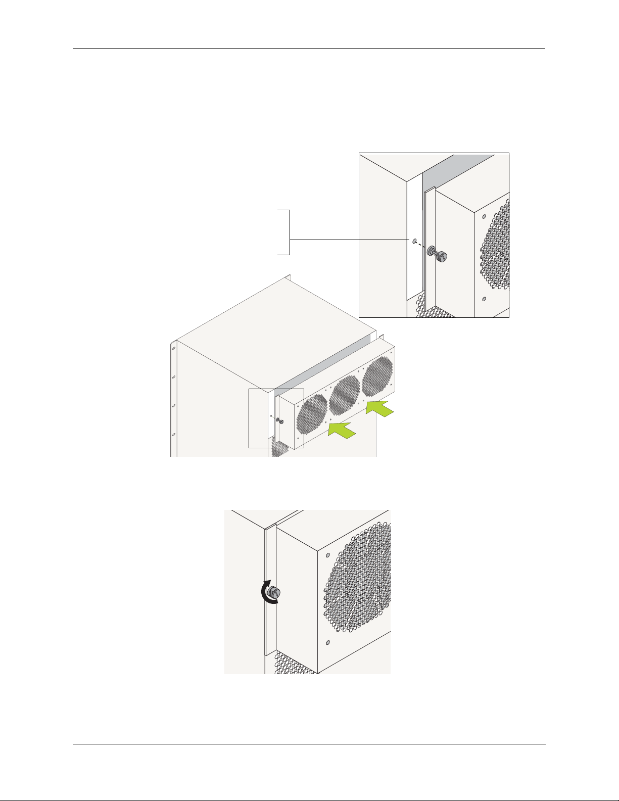
Chassis and Power Supplies Chassis Fan Tray
Installing the New Fan Tray
1 Align the new fan tray’s captive screws with the threaded holes at the rear of the chassis. The fan tray
has an onboard power connector that plugs into a power connector socket on the chassis. In addition to
aligning the captive screws, be sure that this power connector is aligned with the power connector socket
on the chassis. Next, push the fan tray straight against the switch chassis.
Align the Captive Screws. Align the fan tray’s
captive screws with the threaded holes in the
chassis. Push the fan tray back against the switch
chassis.
Aligning the Captive Screws
2 When the attachment flanges are flush against the chassis rear panel, tighten the captive screws.
Tighten the Captive Screws. When
the attachment flanges are flush
against the chassis’ rear panel,
tighten the captive screws.
Tightening the Captive Screws
OmniSwitch 9000 Series Hardware Users Guide June 2007 page 2-39
Page 60

Chassis Airflow Chassis and Power Supplies
Chassis Airflow
The fan tray pulls air from the air intake vents located at the bottom-front and left and right sides of the
chassis. The air is directed vertically through the chassis’ module compartment and past the NI and CMM
circuit boards. Airflow is then exhausted through the fan tray at the top-rear of the chassis.
Important. Maintain a clearance of at least six inches at the front and back of the chassis, as well as at the
left and right sides. Otherwise, airflow may become restricted. Restricted airflow can cause your switch to
overheat; overheating can lead to switch failure.
The figure below provides illustrated airflow diagrams for OS9800, OS9700, and OS9600 switches. See
page 2-43 for an airflow diagram describing the chassis’ power supply bays.
Chassis Module
Compartment
2. Airflow. The air from the
intake vents is directed up
through the chassis’ module
compartment and past the NI
and CMM circuit boards.
This airflow provides
required cooling for the modules and other chassis components.
3. Air Exhaust. The airflow is exhausted through
the fan tray at the rear of
the chassis.
Fan Tray
1. Air Intake. The fan tray
pulls air from the three air
intake vents located at the
bottom of the chassis.
Air Intake Vents
Airflow for OS9800 Switches
page 2-40 OmniSwitch 9000 Series Hardware Users Guide June 2007
Page 61

Chassis and Power Supplies Chassis Airflow
See page 2-43 for an airflow diagram describing the chassis’ power supply bays
Chassis Module
Compartment
2. Airflow. The air from the
intake vents is directed up
through the chassis’ module
compartment and past the NI
and CMM circuit boards.
This airflow provides
required cooling for the modules and other chassis components.
1. Air Intake. The fan tray
pulls air from the three air
intake vents located at the
bottom of the chassis.
Fan Tray
3. Air Exhaust. The airflow is exhausted through
the fan tray at the rear of
the chassis.
Air Intake Vents
Airflow for OS9700 Switches
OmniSwitch 9000 Series Hardware Users Guide June 2007 page 2-41
Page 62

Chassis Airflow Chassis and Power Supplies
See page 2-43 for an airflow diagram describing the chassis’ power supply bays.
Fan Tray
3.Air Exhaust. The airflow
is exhausted through the right
side and rear of the chassis.
2.Airflow. The air from the
intake vents is directed up
through the chassis’ module
compartment and past the NI
and CMM circuit boards.
This airflow provides
required cooling for the modules and other chassis components.
1. Air Intake. The fan tray
pulls air from the air intake
vent located at the left side
of the chassis.
Air Vent
Chassis Module
Compartment
Airflow for OS9600 Switches
page 2-42 OmniSwitch 9000 Series Hardware Users Guide June 2007
Page 63

Chassis and Power Supplies Chassis Airflow
Power Supply Fans
The chassis fan tray does not regulate power supply temperature. Instead, a cooling fan is installed in each
power supply. Since power supply bays are self-contained, each fan operates independently, cooling only
its associated power supply. Refer to the diagram below for more information.
OS9600 Switch
1. Air Intake. The fan unit,
located behind each power
supply front panel, pulls air
from the air intake vent.
OS9700 Switch
2. Airflow. The air from the
intake vent is directed front-toback through the power supply
housing. The airflow provides
required cooling for the power
supply’s internal components.
3. Air Exhaust. Airflow is
exhausted through a corresponding vent in the rear
panel of the chassis. Refer
page 2-2 for vent loca-
to
tions.
Note:
For OS9700 switches only,
airflow for the top power
supply is exhausted through
the chassis fan tray.
Airflow for Power Supplies
See page 2-16 for detailed power supply front panel and LED information.
OS9800 Switch
OmniSwitch 9000 Series Hardware Users Guide June 2007 page 2-43
Page 64

Chassis Airflow Chassis and Power Supplies
Blank Cover Panels and Chassis Airflow
Blank cover panels are provided with your switch and are used to cover empty CMM and NI slots, as well
as empty power supply bays. These cover panels play an important role in chassis airflow and temperature
management. If your switch is not fully populated and blank cover panels are not installed over empty slot
locations, airflow is affected. When blank cover panels are missing, air does not take the direct route from
the air intake vents, up through the chassis module compartment, and out through the fan tray. Instead, a
portion of the airflow is allowed to be drawn in through the front module compartment of the chassis. As a
result, normal airflow is disrupted and an extra task is placed on the fan tray to cool the chassis. Refer to
the figure below for more information.
Cover panels also provide protection for module processor boards and other sensitive internal switch
components by closing off a chassis that is not fully populated.
Note. Because they regulate airflow and help protect internal chassis components, blank cover panels
should be installed over empty module slots and power supply bays at all times.
Missing Cover Panels.
Missing cover panels affect
airflow by allowing air to be
drawn in through the front
module compartment of the
chassis. As a result, the direct
route from the air intake
vents to the fan tray exhaust
is disrupted.
For optimal airflow and
chassis component protection, always install blank
cover panels over empty
module slots and power supply bays.
Fan Tray
Air leakage due to missing
cover panels
Chassis Module
Compartment
Air Intake Vents
Effects of Missing Blank Panels on Chassis Airflow
page 2-44 OmniSwitch 9000 Series Hardware Users Guide June 2007
Page 65

3 Installing and Managing
Power over Ethernet (PoE)
Power over Ethernet (PoE) is supported on OmniSwitch 9600, 9700, and 9800 switches and provides
inline power directly from the switch’s Ethernet ports. Powered Devices (PDs) such as IP phones, wireless LAN stations, Ethernet hubs, and other access points can be plugged directly into the Ethernet ports.
From these RJ-45 ports, provided on Alcatel-Lucent’s OS9-GNI-P24 modules, the devices receive both
electrical power and data flow.
Since the feature reduces devices’ dependence on conventional power sources, PoE eliminates many
restrictions that traditional electrical considerations have imposed on networks.
In a PoE configuration, power source equipment (PSE) detects the presence of a PD and provides an electrical current that is conducted along the data cable. The PD operates using the power received via the
Ethernet data cable; no connection to an additional power source (e.g., an AC wall socket) is required.
Note on Terminology. There are several general terms used to describe this feature. The terms Power
over Ethernet (PoE), Power over LAN (PoL), Power on LAN (PoL), and Inline Power are synonymous
terms used to describe the powering of attached devices via Ethernet ports. For consistency, this chapter
and the OmniSwitch CLI Reference Guide refer to the feature as Power over Ethernet (PoE).
Additional terms, such as Powered Device (PD) and Power Source Equipment (PSE) are terms that are not
synonymous with PoE, but are directly related to the feature:
• PD refers to any attached device that uses a PoE data cable as its only source of power. Examples
include access points such as IP telephones, Ethernet hubs, wireless LAN stations, etc.
• PSE refers to the actual hardware source of the electrical current for PoE. In the case of OS9600,
OS9700, and OS9800 switches, the PSE is the peripheral power shelf unit; 510W and 360W power
supplies are exclusive for the OS9600 only.
OmniSwitch 9000 Series Hardware Users Guide June 2007 page 3-1
Page 66

In This Chapter Installing and Managing Power over Ethernet (PoE)
In This Chapter
This chapter provides specifications and descriptions of hardware and software used to provide PoE for
attached devices.
The chapter also provides information on configuring PoE settings on the switch through the Command
Line Interface (CLI). CLI commands are used in the configuration examples; for more details about the
syntax of commands, see the CLI Reference Guide. Topics and configuration procedures described in this
chapter include:
• Power over Ethernet Specifications on page 3-3
• Power over Ethernet Overview on page 3-4
• Power over Ethernet Components on page 3-6
• Power Shelf and PoE Port Guidelines on page 3-9
• Setting Up Power over Ethernet Hardware on page 3-19
• Power Shelf Slot Numbering on page 3-22
• Viewing Power Status on page 3-22
• Configuring Power over Ethernet Parameters on page 3-23
• Understanding Priority Disconnect on page 3-27
• Monitoring Power over Ethernet via the CLI on page 3-32
• Power over Ethernet Tutorial on page 3-34
Note. You can also monitor all chassis components and manage many chassis features, including Power
over Ethernet, with WebView, Alcatel-Lucent’s embedded web-based device management application.
WebView is an interactive and easy-to-use GUI that can be launched from OmniVista or a web browser.
Please refer to WebView’s online documentation for more information.
page 3-2 OmniSwitch 9000 Series Hardware Users Guide June 2007
Page 67

Installing and Managing Power over Ethernet (PoE) Power over Ethernet Specifications
Power over Ethernet Specifications
The table below lists general specifications for Alcatel-Lucent’s Power over Ethernet support. For more
detailed power supply and Power Source Equipment (PSE) specifications, refer to “OS-IP-SHELF PoE
Power Shelf” on page 3-6 and “510W/360W Power Supply” on page 3-8.
IEEE Standards supported
Default PoE administrative status Enabled
Default PoE operational status Disabled (PoE must be activated on a slot-by-
Platforms supporting PoE OmniSwitch 9600, 9700, 9800
Modules supporting PoE OS9-GNI-P24
Cable distances supported 100 meters (approx.)
Total number of PoE-capable ports per module 24
Maximum number of OS9-GNI-P24 modules per chas-
sis
Maximum number of PoE-capable ports per chassis 96 (OS9600); 192 (OS9700); 384 (OS9800)
Default amount of inline power allocated for each port 15400 milliwatts
Range of inline power allowed for each port 3000–18000 milliwatts
Default amount of inline power allocated for each slot 260 watts
Range of inline power allowed for each slot 37–260 watts
Power Supply Support for Powered Devices (PDs) Refer to “Power Shelf and PoE Port Guide-
IEEE 802.3af DTE Power via MDI;
IEEE 802.3u 10Base-T/100Base-Tx/FX
slot basis via the lanpower start command.)
4 (OS9600); 8 (OS9700); 16 (OS9800)
lines” on page 3-9
OmniSwitch 9000 Series Hardware Users Guide June 2007 page 3-3
Page 68

Power over Ethernet Overview Installing and Managing Power over Ethernet (PoE)
Power over Ethernet Overview
OmniSwitch 9800
Connections to AC Power Source
1
5
IP Telephones
IP Telephones
Ethernet Cables
OK1
OK2
1x 3x 5x 7x 9x 11x 13x 15x 17x 19x 21x 23x
4
24x2x
UPS or Other Valid
Power Source
2
Chassis-to-Power-Shelf Cables
5
Wireless LAN Devices
3
Power Shelf
(No additional AC power source
required for attached PDs.)
UPS or Other Valid
Power Source
Power over Ethernet Application Example
The diagram above shows the power path from a conventional power source—e.g., an Uninterruptible
Power Source (UPS)—to attached powered devices (PDs) located in a separate area of the building or
campus. PDs include IP telephones and wireless LAN devices.
Important. Alcatel-Lucent recommends that PoE-enabled switches with attached IP telephones should
have operational power supply redundancy at all times for 911 emergency requirements. In addition, both
the chassis and the power shelf should be plugged into an Uninterruptible Power Source (UPS).
The items listed below (1–5) describe the major components and connections in the application example.
Refer to the corresponding numbers (1–5) in the diagram above for specific locations of these major
components and connections.
1 The power supplies in the OS9800 chassis are plugged into an AC power source located in the
Building One data center. These power supplies provide power for basic switch operations.
2 Also in the Building One data center, an OS-IP-SHELF is attached to the OS9800 via DB-25
chassis-to-power-shelf cables. (Connections for the chassis-to-power-shelf cables are located on the rear
panel of the switch chassis, as well as the rear panel of the separate OS-IP-SHELF.)
page 3-4 OmniSwitch 9000 Series Hardware Users Guide June 2007
Page 69

Installing and Managing Power over Ethernet (PoE) Power over Ethernet Overview
3 The power shelf includes four power supply bays of its own. These power supplies provide inline
power through the switch’s backplane to the Ethernet ports located on OS9-GNI-P24 modules. The power
supplies in the OS-IP-SHELF are plugged into an AC power source in the Building One data center.
Note. PoE is supported only on Ethernet ports in OS9-GNI-P24 modules.
4 Standard Category 5 Ethernet cables are connected to the RJ-45 ports on the switch’s OS9-GNI-P24
module. Like many typical campus network layouts, the Ethernet cable runs from the data center to a
separate building nearby. (The maximum cable distance is approximately 100 meters.)
5 The Ethernet cables are then plugged into PDs (i.e., IP telephones and wireless LAN devices), which
are used by operators and staff in the adjacent Building Two. Both electrical power and data flow are
provided via these standard Category 5 Ethernet cables. No additional AC power source (such as a 110V
wall socket) is required for any of these attached PDs.
Note. Because OS9-GNI-P24 modules fully support 10/100/1000 Ethernet connectivity, you may also
attach non-PD equipment—such as computer workstations, printers, servers, etc.—to the OS9-GNI-P24
ports. See Chapter 5, “Network Interface (NI) Modules,” for more information on the OS9-GNI-P24.
OmniSwitch 9000 Series Hardware Users Guide June 2007 page 3-5
Page 70

Power over Ethernet Components Installing and Managing Power over Ethernet (PoE)
Power over Ethernet Components
OS-IP-SHELF PoE Power Shelf
The OS-IP-SHELF unit is the chassis’ peripheral power shelf, which provides the electrical current used
for PoE ports. The OS-IP-SHELF contains up to four load sharing power supply modules can be used for a
maximum of 2400W PoE power source. Redundancy is supported when two modules are in use.
Note. Use the appropriate Power Cable(s) provided by Alcatel-Lucent with the OS-IP-SHELF power
supplies.
Note. You must not connect OS-IP-SHELF at the same time a 510W/360W power supply is plugged in
and vice versa on the OS9600. There is a rotating plate on the back of the OS9600 chassis that prevents the
OS-IP-SHELF and 510W/360W power supplies from being connected at the same time. The 510W/360W
power supplies cannot be used on the OS9700 or OS9800 switches.
The OS-IP-SHELF must be properly connected to the chassis and fully operational for PoE to function.
For information on setting up the OS-IP-SHELF, refer to the sections below:
4
Y CORDS.
Y BE EQUIPPED
IC
WER SUPPLY
HIS UNIT MA
: T
E POWER SUPPL
RISK OF ELECTR
TIPL
TION
THE
VICING UNIT.
CAU
ONNECT ALL PO
S
WITH MUL
REDUCE
DISC
VENIR LES
ORDON
TO
!
SHOCK,
: CET APPAREIL PEUT
ATION
CORDS BEFORE SER
DEBRANCHEZ TOU
PLUS D'UN C
LES CORDONS
ON.
ENTION
TION. AFIN DE PRE
ATI
D'ALIMENT
NT DE FAIRE
A
QUES,
ATT
AVA
REPAR
COMPORTER
LA
D'ALIMENT
CHOCS ELECTRI
3
Y CORDS.
Y BE EQUIPPED
IC
WER SUPPLY
.
HIS UNIT MA
: T
E POWER SUPPL
RISK OF ELECTR
TIPL
TION
THE
VICING UNIT
CAU
ONNECT ALL PO
S
WITH MUL
REDUCE
TOU
VENIR LES
ORDON
TO
!
SHOCK, DISC
TION
: CET APPAREIL PEUT
CORDS BEFORE SER
DEBRANCHEZ
PLUS D'UN C
LES CORDONS
ON.
D'ALIMENTA
NT DE FAIRE
QUES,
PORTER
ATTENTION
AVA
REPARATI
COM
LA
D'ALIMENTATION. AFIN DE PRE
CHOCS ELECTRI
2
Y
Y CORDS.
Y BE EQUIPPED
WER SUPPL
HIS UNIT MA
: T
E POWER SUPPL
RISK OF ELECTRIC
TION
THE
VICING UNIT.
CAU
ONNECT ALL PO
S
WITH MULTIPL
REDUCE
TOU
VENIR LES
ORDON
TO
!
SHOCK, DISC
DS BEFORE SER
: CET APPAREIL PEUT
COR
DEBRANCHEZ
PLUS D'UN C
LES CORDONS
ON.
ATI
D'ALIMENTATION
NT DE FAIRE
ATION. AFIN DE PRE
QUES,
PORTER
ATTENTION
AVA
REPAR
COM
LA
D'ALIMENT
OS-IP-SHELF
M
T
AC
DC
OVER
TEMP
CHOCS ELECTRI
1
Y
Y CORDS.
Y BE EQUIPPED
IC
WER SUPPL
.
HIS UNIT MA
: T
E POWER SUPPL
RISK OF ELECTR
TIPL
TION
VICING UNIT
CAU
ONNECT ALL PO
S
WITH MUL
REDUCE THE
DISC
TOU
VENIR LES
ORDON
TO
!
SHOCK,
DS BEFORE SER
TION
: CET APPAREIL PEUT
A
COR
AIRE
DEBRANCHEZ
PLUS D'UN C
LES CORDONS
ON.
D'ALIMENT
NT DE F
ATION. AFIN DE PRE
QUES,
PORTER
ATTENTION
AVA
REPARATI
COM
LA
D'ALIMENT
CHOCS ELECTRI
AC OK
OK
DC
OVER
TEMP
OK
OK
AC OK
OK
DC
OVER
TEMP
AC OK
OK
DC
OVER
TEMP
OS-IP-SHELF PoE Power Shelf
The three power supplies in IP-SHELF supports sixteen and eight OS9-GNI-P24 NIs in OS9800 and
OS9700 chassis respectively, a fourth power supply can be used as a Redundant Power Supply. For
OS9600 chassis, only two power supplies in IP-SHELF supports four OS9-GNI-P24 NIs. The third power
supply can be used as a Redundant Power Supply.
page 3-6 OmniSwitch 9000 Series Hardware Users Guide June 2007
Page 71

Installing and Managing Power over Ethernet (PoE) Power over Ethernet Components
OS-IP-SHELF Chassis Specifications
Chassis Width (rack-mount flanges not included) 17 3/8 inches, approx.
Overall Width (including rack-mount flanges) 19 1/8 inches
Height 5 3/16 inches, approx.
Height (rack units) 3 RU
Chassis Depth (power supplies not installed) 15 3/16 inches, approx.
Chassis Depth (power supplies installed; cords not included) 15 3/4 inches, approx.
Ambient Temperature 0 to +70 deg C, operating;
-40 to +85 deg C, non-operating
Humidity 5% to 90% Relative Humidity
(Operating);
0% to 95% Relative Humidity
(Storage)
Altitude 10000 feet at +32 deg C, operat-
ing; 50000 feet, non-operating
OmniSwitch 9000 Series Hardware Users Guide June 2007 page 3-7
Page 72

Power over Ethernet Components Installing and Managing Power over Ethernet (PoE)
510W/360W Power Supply
The 510W and 360W power supplies can be used as an alternate power source for PoE. A single 510W
power supply allocates 390W for the PoE functionality; Similarly, a single 360W power supply allocates
240W for the PoE functionality. Only one power supply module can be installed per switch, not both.
These power modules do not support load sharing.
Note. The 360W/510W power supplies are only supported on OS9600 switches and not on OS9700/
OS9800 switches.
Note. Use the appropriate Power Cable(s) provided by Alcatel-Lucent with the 360W/510W power
supplies.
Note. You must not connect OS-IP-SHELF at the same time a 510W/360W power supply is plugged in.
510W AC Power Supply
360W AC Power Supply
page 3-8 OmniSwitch 9000 Series Hardware Users Guide June 2007
Page 73

Installing and Managing Power over Ethernet (PoE) Power Shelf and PoE Port Guidelines
Power Shelf and PoE Port Guidelines
The tables below list PoE power support for both non-redundant and redundant power supply
configurations.
Note. PoE power supply redundancy is not related to the switch’s chassis power supply redundancy. For
information on chassis power supply redundancy and minimum power requirements for switch operations, refer to the “Chassis and Power Supplies” chapter.
Non-Redundant Power Supply Configurations
Use the table below to determine the minimum number of power supplies needed in a non-redundant
PoE configuration.
Power Supplies Power
1600 watts
2 1200 watts
3 1800 watts
4 2400 watts
For example, a PoE configuration with 192 powered devices, each requiring 7 watts of power, uses a total
of 1344 watts. Because two power supplies support up to 1200 watts only, a total of three power supplies
is required for this non-redundant 1344 watt PoE application.
OmniSwitch 9000 Series Hardware Users Guide June 2007 page 3-9
Page 74

Power Shelf and PoE Port Guidelines Installing and Managing Power over Ethernet (PoE)
Redundant Power Supply Configurations
Power supply redundancy is defined as having at least one power supply more than the minimum requirement (i.e., N+1). With redundancy, if a power supply is removed from the power shelf or fails unexpectedly, the remaining power supplies automatically take up the load without disrupting PoE support.
Use the table below to determine the minimum number of power supplies needed in a redundant
PoE configuration
Power Supplies Power
1+1 600 watts
2+1 1200 watts
For example, a PoE configuration with 92 powered devices, each requiring 7.5 watts of power, uses a total
of 690 watts. Because 1+1 power supplies support up to 600 watts only, a configuration of 2+1 is required
for this application.
Important. Alcatel-Lucent recommends that PoE-enabled switches with attached IP telephones should
have operational power supply redundancy at all times for 911 emergency requirements. In addition, both
the chassis and the power shelf should be plugged into an Uninterruptible Power Source (UPS). Power
supply redundancy must also be enabled in the system software (see “Setting PoE Redundancy Status” on
page 3-26).
page 3-10 OmniSwitch 9000 Series Hardware Users Guide June 2007
Page 75

Installing and Managing Power over Ethernet (PoE) Setting Up Power over Ethernet Hardware
Setting Up Power over Ethernet Hardware
Setting up PoE hardware involves the following general steps:
• Positioning the Power Shelf on page 3-11
• Installing the Power Supplies on page 3-15
• Connecting the Power Shelf to the Chassis on page 3-19
• Connecting Powered Devices on page 3-22
Note. Before beginning these steps, be sure to review the basic guidelines outlined below.
Basic Guidelines for Setting Up PoE Hardware
Positioning the Power Shelf
When positioning the power shelf for installation, please note the following important guidelines:
• In free-standing (i.e., non-rack-mounted) installations, the power shelf cannot support the weight of a
switch chassis. As a result, do not attempt to stack an OS9600, OS9700, or OS9800 chassis directly on
top of the power shelf at any time; damage to the power shelf chassis and its components may result.
For free-standing installations, the power shelf must either be placed on top of, or alongside, the switch
chassis.
• The cables connecting the power shelf to the chassis are approximately 49 inches in length. When
positioning the power shelf for installation, be sure that the unit is close enough to the OS9600,
OS9700, or OS9800 chassis to provide a connection.
• For rack-mounted installations, the power shelf may be installed either above or below the switch
chassis.
OmniSwitch 9000 Series Hardware Users Guide June 2007 page 3-11
Page 76

Setting Up Power over Ethernet Hardware Installing and Managing Power over Ethernet (PoE)
Rack-Mounting the Power Shelf
Refer to the important guidelines below before installing the power shelf in a rack.
• If the power shelf was not shipped with power supplies installed, it is recommended that you install the
power supplies after you have rack mounted the switch. This will minimize the weight of the chassis
when positioning and installing the power shelf. For detailed information on installing power supplies,
refer to page 3-15.
• It is recommended that two people install the power shelf in the rack—one person to hold the unit and
position it in the rack, and a second person to secure the unit to the rack using the rack attachment
screws (not provided).
• Alcatel-Lucent provides two rack-mount flanges with each power shelf. These flanges support standard
19-inch rack mount installations. These flanges must be attached to the power shelf before the power
shelf can be rack mounted.
Note. If you are installing the power shelf in a 23-inch wide rack, Alcatel-Lucent offers optional 23-inch
rack-mounting hardware. For more information, contact your Alcatel-Lucent representative.
• Alcatel-Lucent does not provide rack-mount screws. Use the screws supplied by the rack vendor.
• To prevent a rack from becoming top heavy, it is recommended that you install heavier equipment at
the bottom of the rack whenever possible.
• If you are installing the power shelf in a relay rack, be sure to install and secure the rack per the rack
manufacturer’s specifications.
page 3-12 OmniSwitch 9000 Series Hardware Users Guide June 2007
Page 77

Installing and Managing Power over Ethernet (PoE) Setting Up Power over Ethernet Hardware
To rack-mount the power shelf, follow the steps below:
1 Align the holes in the provided rack-mount flanges with the threaded holes located in the left and right
sides of the unit.
4
3
2
D
E
P
.
IP
S
U
D
Q
R
E
O
1
E
C
LY
B
Y
L
P
P
P
AY
IC
P
U
R
M
T
S
IT
C
SU
R
E
R
E
N
L
E
W
U
E
W
O
F
IS
O
IT.
P
H
O
L
P
N
K
: T
L
E
L
IS
U
A
R
G
IP
T
E
C
IN
LT
TION
E
U
IC
U
N
TH
T
V
E
N
M
R
S
U
C
CA
O
H
E
E
E
U
C
S
N
IT
S
L
P
D
E
IS
U
O
E
IR
IL
W
R
R
E
D
O
N
, D
O
T
R
R
E
K
O
F
A
V
Z
O
C
T
E
P
E
E
B
S
O
C
P
R
H
S
N
H
N
!
N
A
C
P
S
D
O
T
E
'U
N
IO
R
D
T
D
D
O
R
RA
: CE
E
S
N
C
TA
B
IR
FI
N
E
LU
CO
E
.
S
D
. A
P
,
FA
E
N
R
IM
S
N
E
L
O
E
L
E
T
D
IO
TI
U
'A
T
T
R
A
D
IQ
N
R
O
TA
R
P
A
ATTENTION
N
T
V
PA
M
E
C
E
A
O
R
IM
LE
C
L
LA
S E
'A
C
D
O
H
C
F
L
E
H
-S
-IP
S
O
M
T
K
O
C
A
K
O
C
D
R
E
V
P
O
M
E
T
2 Attach the flanges to the power shelf using the Phillips-head screws provided. Be sure to tighten each
of the screws firmly using a Phillips screwdriver.
3 After both rack-mount flanges are secured to the unit, mark the holes on the rack where the power shelf
is to be installed.
4 Lift and position the power shelf until the rack-mount flanges are flush with the rack post.
5 Align the holes in the flanges with the rack holes that were marked in step 3.
OmniSwitch 9000 Series Hardware Users Guide June 2007 page 3-13
Page 78

Setting Up Power over Ethernet Hardware Installing and Managing Power over Ethernet (PoE)
6 Once the holes are aligned, insert a rack mount screw (not provided) through the bottom hole of each
flange. Tighten both screws until they are secure.
4
3
2
D
E
P
.
P
S
UI
D
Q
R
1
E E
CO
Y
L
B
Y
L
Y
P
PP
A
IC
P
R
M
T
SU
T
SU
I
C
R
E
R
E
N
E
W
EL
W
S U
O
.
F
I
IT
O
H
P
PO
L
T
N
K
:
L
E
S
L
U
N
A
RI
G
IP
T
IO
E
T
C
IN
L
T
H
IC
T
U
NE
V
E
A
MU
N
R
S
UT
C
C
O
E
E
E
C
S
N
ITH
S
L
P
DU
IS
R
U
O
E
I
W
RE
D
R
EIL
O
,
O
T
R
RD
EN
K
O
F
A
V
O
T
E
P
E
EZ
S
OC
C
P
B
R
H
S
N
H
N
!
N
A
P
S
D
O
T
E
'U
NC
R
E
D
TIO
A
D
D
O
R
A
C
R
:
E
S
C
T
O
IN
B
U
N
IR
F
C
E
L
A
EN
.
O
S
A
I
D
.
P
,
F
E
N
T
IM
N
E
L
O
ER
L
ES
N
T
D
IO
A
TI
U
E
T
T
R
A
T
Q
D'
A
R
O
T
T
RI
P
AN
A
A
N
T
V
M
E
C
EP
A
E
O
R
IM
L
C
L
E
LA
S
'A
C
D
O
H
C
OS-IP-SHELF
M
T
K
O
C
A
K
O
C
D
R
E
V
P
O
M
E
T
Note. Be sure to install the screws in the bottom hole of each flange, as shown, before proceeding.
7 Once the screws at the bottom of each flange are secure, install the remaining two rack mount screws.
Be sure that all screws are securely tightened.
page 3-14 OmniSwitch 9000 Series Hardware Users Guide June 2007
Page 79
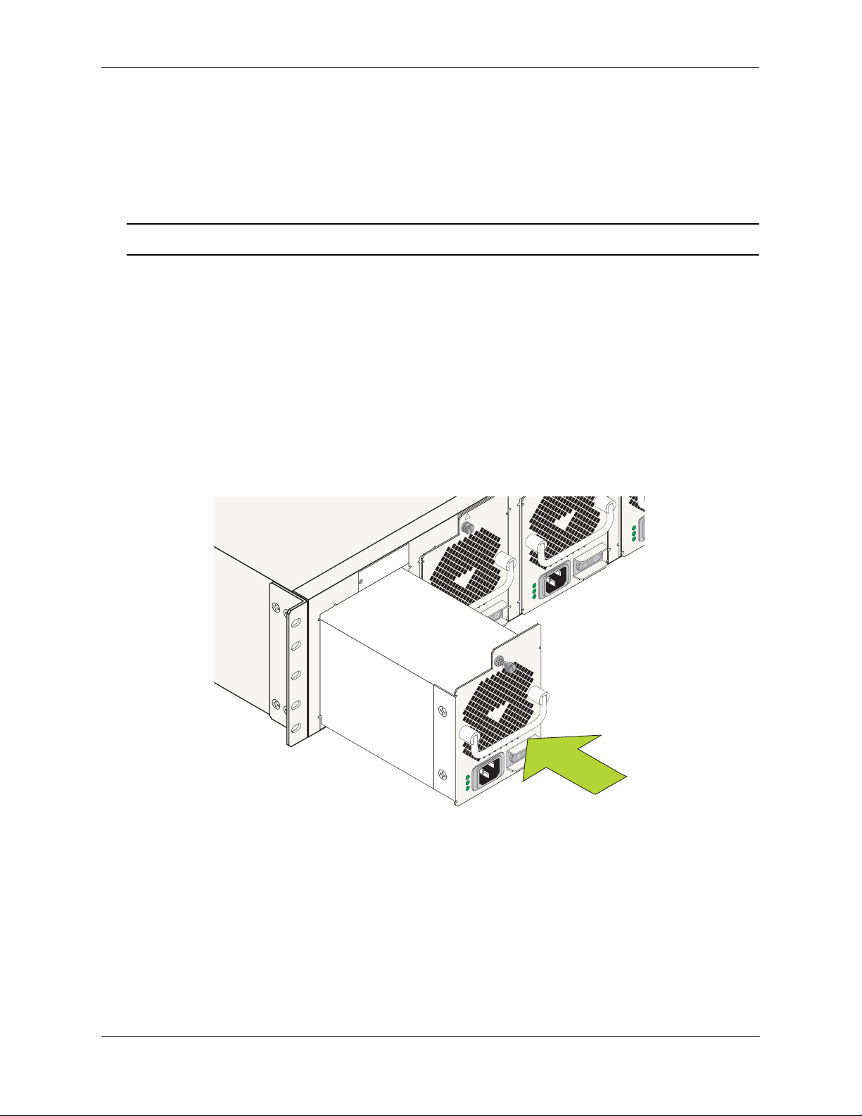
Installing and Managing Power over Ethernet (PoE) Setting Up Power over Ethernet Hardware
2
Installing the Power Supplies
Preparation
If there are blank cover plates over bays where power supplies are to be installed, loosen the screws,
located at the top of each cover plate. Remove the cover plates and set the plates and screws aside.
Note. Be sure to replace cover plates over any unused power supply bays.
Installation Steps
Install the power supplies in the power shelf by following the steps below.
1 First, be sure that you do not install the power supply upside down. When orienting the power supply,
note that the on/off switch and power cord socket are located at the bottom of the power supply and the fan
is located at the top of the power supply.
2 With one hand, grasp the handle at the front of the power supply. Place your other hand under the
power supply casing to support its weight.
3 Carefully insert the rear of the casing into the power supply bay and slide the power supply back until
its connector meets the chassis backplane connector.
Y
Y BE EQUIPPED
IC
.
: THIS UNIT MA
E POWER SUPPLY CORDS.
N
IO
TIPL
T
U
VICING UNIT
A
C
WITH MUL
REDUCE THE RISK OF ELECTR
TO
!
SHOCK, DISCONNECT ALL POWER SUPPL
DS BEFORE SER
ET APPAREIL PEUT
ATION
: C
COR
N
AIRE
IO
DEBRANCHEZ TOUS
T
LES CORDONS
N
E
T
QUES,
D'ALIMENT
ATION. AFIN DE PREVENIR LES
T
A
AVANT DE F
REPARATION.
COMPORTER PLUS D'UN CORDON
LA
D'ALIMENT
CHOCS ELECTRI
1
K
O
AC
K
O
DC
VER
O
TEMP
K
O
C
A
K
O
C
D
P
OVER
TEM
K
O
AC
K
O
DC
VER
P
O
TEM
K
AC O
OK
DC
VER
P
O
TEM
4 Continue sliding the power supply back until the front panel meets the front of the chassis. Do not
force the power supply into the bay. Otherwise you can damage the connectors.
OmniSwitch 9000 Series Hardware Users Guide June 2007 page 3-15
Page 80

Setting Up Power over Ethernet Hardware Installing and Managing Power over Ethernet (PoE)
5 Tighten the captive screw, located at the top of the power supply’s front panel. Be sure not to over-
tighten the captive screw. If you use a screwdriver, the torque used to tighten the screw must not exceed
2.3 foot-pounds.
1
OK
AC
OK
DC
OVER
TEMP
OK
AC
OK
DC
OVER
TEMP
6 Install all remaining power supplies by repeating steps 1 through 5 for each power supply.
7 Verify that the on/off switch for each installed power supply is in the off ( O ) position.
8 For each power supply, plug the power cord connector into the power supply socket and then plug the
power cord into an easily-accessible, properly grounded outlet or Uninterruptible Power Source (UPS). Be
sure that each power supply is plugged into its own dedicated AC outlet or power source; do not use an
extension cord or power strip.
Note. For information on removing power supplies, refer to “Removing the Power Supplies” on
page 3-17.
page 3-16 OmniSwitch 9000 Series Hardware Users Guide June 2007
Page 81

Installing and Managing Power over Ethernet (PoE) Setting Up Power over Ethernet Hardware
Removing the Power Supplies
Note. If applicable, it is recommended that you power off the power supply, disconnect the power cord
from the electrical source, and unplug the cord from the power supply’s front panel before proceeding.
1 Loosen the captive screw, located at the top of the power supply’s front panel. If necessary, use a flat-
blade screwdriver to loosen the screw. Be sure that the captive screw is completely disengaged from the
threaded hole in the chassis before continuing.
1
OK
AC
OK
DC
OVER
TEMP
OK
AC
OK
DC
OVER
TEMP
Note. Alcatel-Lucent provides factory-installed blank cover plates for empty module slots. Do not remove
these cover plates as they play an important role in chassis ventilation.
OmniSwitch 9000 Series Hardware Users Guide June 2007 page 3-17
Page 82

Setting Up Power over Ethernet Hardware Installing and Managing Power over Ethernet (PoE)
2
IP
P
DS
.
2 With one hand, grasp the handle at the front of the power supply and slowly pull the power supply out
of the power supply bay. Do not pull the power supply completely out of the bay with one hand.
U
Y
Y BE EQ
A
ER SUPPL
W
.
WER SUPPLY COR
IS UNIT M
O
G UNIT
ISK OF ELECTRIC
E P
: TH
R
ECT ALL PO
TIPL
VICIN
THE
NN
SER
IR LES
TOUS
DON
N
CAUTION
VE
AREIL PEUT
WITH MUL
REDUCE
PP
TO
NS
HOCK, DISCO
!
S
RDS BEFORE
TION
: CET A
A
ORDO
, DEBRANCHEZ
CO
AIRE
S
PLUS D'UN COR
N.
F
UE
LES C
TER
IQ
TION. AFIN DE PRE
A
OR
NT DE
D'ALIMENT
ARATIO
A
ATTENTION
ENT
EP
AV
COMP
LA R
D'ALIM
CHOCS ELECTR
1
K
O
AC
K
O
C
D
ER
V
P
O
TEM
OK
AC
K
O
DC
VER
P
O
TEM
COK
A
K
O
C
D
ER
V
P
O
TEM
OK
AC
K
O
DC
VER
P
O
M
TE
3 When the power supply is pulled out far enough (about 10”), place your other hand under the power
supply casing to support its weight.
4 Continue pulling the power supply out until it is removed from the chassis.
5 Set the power supply aside on a clean, static-free surface.
6 Remove all remaining power supplies by repeating steps 1 through 5.
Note. For information on removing power supplies, refer to “Installing the Power Supplies” on page 3-15.
page 3-18 OmniSwitch 9000 Series Hardware Users Guide June 2007
Page 83

Installing and Managing Power over Ethernet (PoE) Setting Up Power over Ethernet Hardware
Connecting the Power Shelf to the Chassis
1 Connect each (female) DB-25 cable connector to a (male) connector port on the rear panel of the power
shelf. Be careful not to bend the connector pins. Secure each connection by tightening the connector’s
captive screws.
2 Next, connect each (male) DB-25 cable connector to a (female) connector port on rear panel of the
switch chassis. Be careful not to bend the connector pins. Secure each connection by tightening the
connector’s captive screws.
Recommendation. When installing the PoE connector cables, plug each cable into the corresponding
connector on both the power shelf and the switch chassis. For example, if a cable is connected to the farleft connector on the power shelf, connect the cable to the far-left connector on the switch chassis. In addition to facilitating a clean, manageable cable installation, this will ensure that the cable lengths will
accommodate most chassis installations.
Rear of Switch Chassis
(Female) DB-25 PoE Connectors
(Male) DB-25 PoE Connectors
Rear of Power Shelf Chassis
Important. The connectors on the rear of the switch chassis and the power shelf chassis are for PoE
power connections only. Never attempt to connect data communication or other equipment to these
connectors.
OmniSwitch 9000 Series Hardware Users Guide June 2007 page 3-19
Page 84

Setting Up Power over Ethernet Hardware Installing and Managing Power over Ethernet (PoE)
Connecting the 360W/510W PoE Power Supply to the Chassis
1 Connect each (male) DB-25 cable connector to a (female) connector port on the rear panel of the 360W
or 510W power supply. Be careful not to bend the connector pins. Secure each connection by tightening
the connector’s captive screws.
2 Next, connect each (male) DB-25 cable connector to a (female) connector port on rear panel of the
switch chassis clearly marked as 360W/510W. Be careful not to bend the connector pins. Secure each
connection by tightening the connector’s captive screws.
Important. The connectors on the rear of the switch chassis and the 360W/510W power supply are for
PoE power connections only. Never attempt to connect data communication or other equipment to these
connectors.
Note. There is a rotating plate on the back of the OS9600 chassis that prevents the OS-IP-SHELF and
510W/360W power supplies from being connected at the same time.
Rotating plate to prevent OS-IP-SHELF and
510W/360W power supplies from being
connected at the same time.
OS-IP-SHELF
510W/360W power supplies
OmniSwitch 9600 power supplies and rotating plate
page 3-20 OmniSwitch 9000 Series Hardware Users Guide June 2007
Page 85

Installing and Managing Power over Ethernet (PoE) Power Shelf Slot Numbering
Power Shelf Slot Numbering
The term slot refers to the position at which a power supply is installed in the power shelf. Power supply
slot numbers are designated “Power Shelf slot 1” through “Power Shelf slot 4,” from left to right. You can
use up to four power supplies on
OS9600 chassis.
Power Shelf slot 1 Power Shelf slot 2 Power Shelf slot 3 Power Shelf slot 4
CAUTION
: THIS UNIT MAY BE EQUIPPED
WITH MULTIPLE POWER SUPPL Y CORDS.
!
TO REDUCE THE RISK OF ELECTRIC
OS-IP-SHELF
SHOCK, DISCONNECT ALL PO WER SUPPLY
CORDS BEFORE SER VICING UNIT.
ATTENTION
: CET APPAREIL PEUT
COMPORTER PLUS D'UN C ORDON
D'ALIMENTATION. AFIN DE PRE VENIR LES
CHOCS ELECTRIQUES, DEBR ANCHEZ T OUS
LES CORDONS
D'ALIMENTATION
AVANT DE FAIRE
LA REPARATION.
1234
the OS9700 and OS9800 chassis and two power supplies on
CAUTION
CAUTION
: THIS UNIT MAY BE EQUIPPED
WITH MULTIPLE POWER SUPPL Y CORDS.
!
TO REDUCE THE RISK OF ELECTRIC
SHOCK, DISCONNECT ALL PO WER SUPPLY
CORDS BEFORE SER VICING UNIT.
ATTENTION
: CET APPAREIL PEUT
COMPORTER PLUS D'UN C ORDON
D'ALIMENTATION. AFIN DE PRE VENIR LES
CHOCS ELECTRIQUES, DEBR ANCHEZ T OUS
LES CORDONS
D'ALIMENTATION
AVANT DE FAIRE
LA REPARATION.
AC OK
DC
OK
OVER
TEMP
AC OK
DC
OK
OVER
TEMP
AC OK
DC
OK
OVER
TEMP
AC OK
DC
OK
OVER
TEMP
Power Shelf Slot Numbering
Note. For information on slot numbering as displayed via the switch’s system software, refer to “Viewing
Power Shelf Status” on page 3-22.
OmniSwitch 9000 Series Hardware Users Guide June 2007 page 3-21
Page 86

Viewing Power Shelf Status Installing and Managing Power over Ethernet (PoE)
Viewing Power Shelf Status
To view the current status of power supplies installed in the power shelf, use the show power command.
Status information includes slot numbering, administrative status, operational status, etc. For detailed
information on show power command output, refer to the OmniSwitch CLI Reference Guide.
Note that information for the PoE power supplies are displayed in the show power command output,
beginning after the last standard (i.e., non-PoE) chassis power supply entry.
For PoE components connected to OS9800 switches, the module slot position for Power Shelf slot 1
always displays as “Module in slot PS-5.” For PoE components connected to OS9700 switches, the
module slot position for Power Shelf slot 1 always displays as “Module in slot PS-4.” For PoE components connected to OS9600 switches, the module slot position for Power Shelf slot 1 always displays as
“Module in slot PS-3.” Refer to the command output below for more information. For a front panel
diagram showing the power shelf slot positions, refer to “Power Shelf Slot Numbering” on page 3-21.
-> show power
Slot PS Wattage Type Status Location
----+----+---------+------+-----------+--------- 1 600 AC UP Internal
2 600 AC UP Internal
3 -- -- -- --
4 600 IP UP External
5 600 IP UP External
6 600 IP UP External
7 600 IP UP External
page 3-22 OmniSwitch 9000 Series Hardware Users Guide June 2007
Page 87

Installing and Managing Power over Ethernet (PoE) Configuring Power over Ethernet Parameters
Configuring Power over Ethernet Parameters
Power over Ethernet Defaults
The following table lists the defaults for PoE configuration:
Parameter Description Command(s) Default Value/Comments
PoE operational status lanpower start or lanpower stop Disabled
Total power allocated to a port lanpower power 15400 milliwatts
Total power allocated to a slot lanpower maxpower 260 watts
Power priority level for a port lanpower priority low
The capacitor detection method lanpower capacitor-detection Disabled
Power supply redundancy lanpower redundant-power Disabled (see important note on
page 3-26)
Priority disconnect status lanpower priority-disconnect Enabled
PoE slot-priority lanpower slot-priority low
Understanding and Modifying the Default Settings
The sections below provide information on each of the key components within the Power over Ethernet
software. They include information on PoE-related CLI commands. For detailed information on PoErelated commands, refer to the OmniSwitch CLI Reference Guide.
For a tutorial that provides a step-by-step walk through a typical PoE software configuration, refer to
page 3-34.
Setting the PoE Operational Status
Enabling PoE
By default, Power over Ethernet is administratively enabled in the switch’s system software. However, in
order to physically activate PoE, you must issue the lanpower start command on a slot-by-slot basis
before any connected PDs will receive inline power.
To activate power to PoE-capable ports in a slot, enter the corresponding slot number only. For example:
-> lanpower start 3
Note. You cannot activate PoE for more than one slot at a time. Also, a valid PoE module (OS9-GNI-P24)
must be installed in the corresponding slot position.
OmniSwitch 9000 Series Hardware Users Guide June 2007 page 3-23
Page 88

Configuring Power over Ethernet Parameters Installing and Managing Power over Ethernet (PoE)
If power to a particular port has been disconnected via the lanpower stop command, you can reactivate
power to the port by specifying both the slot and port in the command line. For example:
-> lanpower start 3/11
Note. You cannot use the slot/port syntax to initially activate PoE on a port. This syntax is intended only
to reactivate power to those ports that have been disconnected via the lanpower stop command. To
initially activate PoE, you must use the lanpower start slot syntax only, as described above.
Disabling PoE
To disable PoE on a particular slot or port, use the lanpower stop command.
To disable PoE on a specific PoE-capable port, enter a slot/port number. For example:
-> lanpower stop 9/22
To disable PoE for all PoE-capable ports in a slot, enter the corresponding slot number only.
For example:
-> lanpower stop 9
Configuring the Total Power Allocated to a Port
Each port is authorized by the system software to use up to a maximum of 18000 milliwatts to power any
attached device.
You can either increase or decrease this value. Values may range from 3000 to 18000 milliwatts.
Increasing the total power allocated to an individual port may provide a more demanding Powered Device
(PD) with additional power required for operation. Decreasing the total power allocated to a port helps
preserve inline power and assists in the overall management of the switch’s power budget.
To increase or decrease the total power allocated to an individual port, use the lanpower power command.
Because you are setting the power allowance for an individual port, you must specify a slot/port number in
the command line. For example, the syntax
-> lanpower 3/12 power 3000
reduces the power allowance on port 12 of the OS9-GNI-P24 module installed in slot 3 to 3000 milliwatts. This new value is now the maximum amount of power the port can use to power any attached
device (until the value is modified by the user).
Configuring the Total Power Allocated to a Slot
Like the maximum port power allowance, the system software also provides a maximum slot-wide power
allowance. The switch allocates 260 watts for each slot installed in the OS9600, OS9700 or OS9800 chassis. However, when the 360W/510W power supply is used, the OS9600 will allocate 240W/390W. respectively. In other words, each slot is authorized by the system software to use up to either 240 or 390 watts to
power all devices connected to its ports depending on the power supply used.
As with the maximum port power allowance, the user can either increase or decrease this value. Values
may range from 37 to 260 watts.
page 3-24 OmniSwitch 9000 Series Hardware Users Guide June 2007
Page 89

Installing and Managing Power over Ethernet (PoE) Configuring Power over Ethernet Parameters
Increasing the total power allocated to a slot may provide more demanding Powered Devices (PDs) with
additional power required for operation. Decreasing the total power allocated to a slot helps preserve
inline power and assists in the overall management of the switch’s power budget.
Important. Before changing the maximum slot-wide power allowance, you must disable PoE for the slot
via the lanpower stop command. Once the new value is assigned, re-enable PoE for the slot via the
lanpower start command.
To increase or decrease the total power allocated to a slot, use the lanpower maxpower command.
Because you are setting the power allowance for an individual slot, you must specify a slot number in the
command line. For example, the syntax
-> lanpower 3 maxpower 80
reduces the power allowance of the OS9-GNI-P24 module installed in slot 3 to 80 watts. This value is now
the maximum amount of power the slot can use to power all attached devices (until the value is modified
by the user).
Setting Port Priority Levels
Because not all Powered Devices (PDs) connected to the switch have the same priority within a customer
network setting, OS9600/OS9700/OS9800 switches allow the user to specify priority levels on a port-byport basis. Priority levels include low, high, and critical.
• Low. This default value is used for port(s) that have low-priority devices attached. In the event of a
power management issue, inline power to low-priority ports is interrupted first (i.e., before critical and
high-priority ports).
• High. This value is used for port(s) that have important, but not mission-critical, devices attached. If
other ports in the chassis have been configured as critical, inline power to high-priority ports is given
second priority.
• Critical. This value is used for port(s) that have mission-critical devices attached, and therefore require
top (i.e., critical) priority. In the event of a power management issue, inline power to critical ports is
maintained as long as possible.
To change the priority level for a particular port, use the lanpower priority command. Because the switch
allows you to set priority levels on a port-by-port basis, be sure to specify slot/port information in the
command line. For example, the syntax
-> lanpower 8/22 priority critical
changes the priority value of port 22 of the OS9-GNI-P24 module installed in slot 8 to the highest priority
level of critical. Now that the default value has been reconfigured, this port should be reserved for those
PDs that are mission critical for network operations.
OmniSwitch 9000 Series Hardware Users Guide June 2007 page 3-25
Page 90

Configuring Power over Ethernet Parameters Installing and Managing Power over Ethernet (PoE)
Setting PoE Redundancy Status
The PoE feature has built-in hardware redundancy. PoE power redundancy status can be configured by the
user. Redundancy is disabled by default. To enable the feature, use the lanpower redundant-power
command. Enter the keyword enable in the command line, as shown:
-> lanpower redundant-power enable
To disable the feature, use the keyword disable in the command line:
-> lanpower redundant-power disable
Important. In order to comply with 911 emergency requirements, PoE power redundancy status must be
enabled at all times.
Note. For information on the priority disconnect function, refer to “Understanding Priority Disconnect” on
page 3-27.
Setting the Capacitor Detection Method
To enable the PowerDsine capacitor detection method use the lanpower capacitor-detection command
by entering lanpower capacitor-detection followed by the slot number of the OS9-GNI-P24 and enable.
For example, to enable the capacitor detection method on the OS9-GNI-P24 with slot number 2 enter:
-> lanpower 2 capacitor-detection enable
To disable it use the lanpower capacitor-detection command by entering lanpower capacitor-detection
followed by the slot number of the OS9-GNI-P24 and disable.
For example, to disable the capacitor detection method on the OS9-GNI-P24 with slot number 2 enter:
-> lanpower 2 capacitor-detection disable
Note. The capacitive detection method should only be enabled to support legacy IP phones only—this
feature is not compatible with IEEE specification 802.3af. Please contact your Alcatel-Lucent sales engineer or Customer Support representative to find out which Alcatel-Lucent IP phone model needs capacitive detection enabled.
page 3-26 OmniSwitch 9000 Series Hardware Users Guide June 2007
Page 91

Installing and Managing Power over Ethernet (PoE) Understanding Priority Disconnect
Understanding Priority Disconnect
The priority disconnect function differs from the port priority function described on page 3-25 in that it
applies only to the addition of powered devices (PDs) in tight power budget conditions. Priority disconnect is used by the system software in determining whether an incoming PD will be granted or denied
power when there are too few watts remaining in the PoE power budget for an additional device. For
example, if there are only 2 watts available in the current PoE power budget and a user plugs a 3.5W
powered device into a PoE port, the system software must determine whether the device will be powered
on. Based on priority disconnect rules, in some cases one or more existing devices may be powered down
in order to accommodate the incoming device. In other cases, the incoming device will be denied power.
Priority disconnect rules involve the port priority status of an incoming device (i.e., low, high, and critical), as well as the port’s physical port number (i.e., 1–24). Understanding priority disconnect rules is
especially helpful in avoiding power budget deficits and the unintentional shutdown of mission-critical
devices when PDs are being added in tight power budget conditions. For detailed information on how
priority disconnect uses port priority and port number criteria for determining the power status of incoming PDs, refer to the illustrated examples on pages 3-28 through 3-31.
Reminder. Priority disconnect only applies when there is inadequate power remaining in the power
budget for an incoming device.
For information setting the priority disconnect status, refer to the section below. For information on setting
the port priority status (a separate function from priority disconnect), refer to “Setting Port Priority
Levels” on page 3-25.
Setting Priority Disconnect Status
By default, priority disconnect is enabled in the switch’s system software. For information on changing
the priority disconnect status, refer to the information below.
Disabling Priority Disconnect
When priority disconnect is disabled and there is inadequate power in the budget for an additional device,
power will be denied to any incoming PD, regardless of its port priority status (i.e., low, high, and critical) or physical port number (i.e., 1–24).
To disable priority disconnect, use the lanpower priority-disconnect command. Because the switch
allows you to set priority disconnect status on a slot-by-slot basis, be sure to specify the slot number in the
command line. For example, the syntax
-> lanpower 2 priority-disconnect disable
disables the priority disconnect function on the OS9-GNI-P24 module installed in slot 2.
Enabling Priority Disconnect
To enable priority disconnect, use the lanpower priority-disconnect command. Be sure to specify the slot
number in the command line. For example, the syntax
-> lanpower 9 priority-disconnect enable
enables priority disconnect on the OS9-GNI-P24 module installed in slot 9.
OmniSwitch 9000 Series Hardware Users Guide June 2007 page 3-27
Page 92

Understanding Priority Disconnect Installing and Managing Power over Ethernet (PoE)
Priority Disconnect is Enabled; Same Priority Level on All PD Ports
Reminder. Priority disconnect examples are only applicable when there is inadequate power remaining to
power an incoming device.
When a PD is being connected to a port with the same priority level as all other ports in the slot, the physi-
cal port number is used to determine whether the incoming PD will be granted or denied power. Lowernumbered ports receive higher priority than higher-numbered ports. In other words, a PD connected to
Port 1 will have a higher power priority than a PD connected to Port 2; a PD connected to Port 23 will
have a higher power priority than a PD connected to Port 24. In order to avoid a power budget deficit,
another port in the slot is disconnected. In determining which port to power off, the system software
disconnects the port with the highest physical port number.
In the example below, there are only 2 watts available in the current PoE power budget. When the additional 3.5W powered device is added to the configuration, the system software must determine whether the
device will be granted or denied power. Because the incoming device is being connected to a lowernumbered physical port, it receives higher priority over the existing PDs and is granted power. Meanwhile, to avoid a deficit in the power budget, the PD connected to the highest physical port number (in this
case, Port 18) is disconnected.
Existing Powered
Devices (PDs)
Low
Low
Low
Low
Low
Low
Incoming Powered Device (PD)
requiring approx. 3.5 watts
Low
!
Current power budget has 2 watts available for incoming PDs
OK1
OK2
1x 3x 5x 7x 9x 11x 13x 15x 17x 19x 21x 23x
Port 2
Port 18
24x2x
Power Shelf
UPS
UPS
Priority Disconnect Example 1: Feature is Enabled; Same Priority Level on All PD Ports
page 3-28 OmniSwitch 9000 Series Hardware Users Guide June 2007
Page 93

Installing and Managing Power over Ethernet (PoE) Understanding Priority Disconnect
Priority Disconnect is Enabled; Incoming PD Port has Highest Priority Level
Reminder. Priority disconnect examples are only applicable when there is inadequate power remaining to
power an incoming device.
When a PD is being connected to a port with a higher priority level than all other ports in the slot, the
incoming PD will automatically be granted power over the other devices, regardless of its physical port
number.
In order to avoid a power budget deficit, another port in the slot is disconnected. In determining which
port to power off, the system software first selects the port with the lowest configured priority level. For
example, if a critical priority device is being added to a slot in which five existing devices are attached to
high priority ports and one device is attached to a low priority port, the low priority port is automatically
disconnected, regardless of its physical port number.
If all existing devices are attached to ports with the same lower priority level, the system software disconnects the port with both the lowest priority level and the highest physical port number. For example, if a
critical priority device is being added to a slot in which six existing devices are attached to high priority
ports, the high priority port with the highest physical port number is automatically disconnected.
In the example below, there are only 2 watts available in the current PoE power budget. When the additional 3.5W powered device is added to the configuration, the system software must determine whether
the device will be granted or denied power. Because the incoming device is being connected to a critical
priority port, and all existing devices are connected to high priority ports, one of the high priority ports
must disconnect in order to accommodate the incoming critical device. According to the priority disconnect rules outlined above, the system software selects the port with the lowest priority level and the highest physical port number. In this example, Port 12 is disconnected.
High
Existing
Powered
Devices (PDs)
High
High
High
High
High
Incoming Powered
Device (PD) requiring
approx. 3.5 watts
Critical
Current power budget has
2 watts available for
incoming PDs
Port 24
OK1
OK2
Port 1
1x 3x 5x 7x 9x 11x 13x 15x 17x 19x 21x 23x
Port 12
!
24x2x
Power Shelf
Priority Disconnect Example 2: Feature is Enabled; Incoming PD Port has Highest Priority Level
UPS
UPS
OmniSwitch 9000 Series Hardware Users Guide June 2007 page 3-29
Page 94

Understanding Priority Disconnect Installing and Managing Power over Ethernet (PoE)
Priority Disconnect is Enabled; Incoming PD Port has Lowest Priority Level
Reminder. Priority disconnect examples are only applicable when there is inadequate power remaining to
power an incoming device.
When a PD is being connected to a port with a lower priority level than all other ports in the slot, the
incoming PD will be denied power, regardless of its physical port number. Devices connected to other
higher-priority ports will continue operating without interruption.
In the example below, there are only 2 watts available in the current PoE power budget. When the additional 3.5W powered device is added to the configuration, the system software must determine whether the
device will be granted or denied power. Because the incoming device is being connected to a high priority
port, and all existing devices are connected to critical priority ports, the incoming high-priority PD is
denied power; meanwhile, the critical priority devices remain powered on. This ensures that no power
budget deficit occurs and that higher priority devices (e.g., mission-critical IP phones) are allowed to operate without interruption.
Incoming Powered Device (PD)
requiring approx. 3.5 watts
Port 1
OK1
OK2
High
1x 3x 5x 7x 9x 11x 13x 15x 17x 19x 21x 23x
!
Critical
Critical
Critical
24x2x
Critical
Port 24
Critical
Power Shelf
Critical
Existing Powered
Devices (PDs)
Current power budget
has 2 watts available
for incoming PDs
Priority Disconnect Example 3: Feature is Enabled; Incoming PD Port has Lowest Priority Level
UPS
UPS
page 3-30 OmniSwitch 9000 Series Hardware Users Guide June 2007
Page 95

Installing and Managing Power over Ethernet (PoE) Understanding Priority Disconnect
Priority Disconnect is Disabled
Reminder. Priority disconnect examples are only applicable when there is inadequate power remaining to
power an incoming device.
When priority disconnect is disabled, power will be denied to any incoming PD, regardless of its port
priority status (i.e., low, high, and critical) or physical port number (i.e., 1–24).
In the example below, there are only 2 watts available in the current PoE power budget. An incoming PD
requiring 3.5W is being attached to a critical priority port. All existing PDs are attached to low priority
ports. If priority disconnect was enabled (the default setting), the incoming device would easily have
power priority over all other connected devices. However, because priority disconnect status is disabled in
this example, any incoming PD is denied power, regardless of its priority level. The incoming 3.5W
device remains powered off. The existing devices connected to low-priority ports continue operating without interruption.
Incoming Powered Device
(PD) requiring approx.
3.5 watts
Port 1
OK1
OK2
1x 3x 5x 7x 9x 11x 13x 15x 17x 19x 21x 23x
Critical
!
Low
Low
Low
24x2x
Low
Port 24
Low
Low
Existing Powered
Devices (PDs)
Current power budget has
2 watts available for
incoming PDs
Priority Disconnect Example 4: Feature is Disabled
UPS
Power Shelf
UPS
OmniSwitch 9000 Series Hardware Users Guide June 2007 page 3-31
Page 96

Monitoring Power over Ethernet via the CLI Installing and Managing Power over Ethernet (PoE)
Monitoring Power over Ethernet via the CLI
To monitor current PoE statistics and settings, use the show lanpower command. The command output
displays a list of all current PoE-capable ports, along with the following information for each port:
• Maximum power allocated to the port, in milliwatts
• Actual power used by the port
• Current port status
• Power priority status
• Power on/off status
Aggregate slot and chassis management information also displays. This information includes:
• Maximum watts allocated to the corresponding slot
• Amount of power budget remaining that can be allocated for PoE modules
• Total amount of power remaining that can be allocated for additional switch functions
• Number of power supplies installed and operating in the power shelf
When entering the show lanpower command, you must include a valid slot number in the command line
syntax. For example:
-> show lanpower 3
Port Maximum(mW) Actual Used(mW) Status Priority On/Off
----+-----------+---------------+--------------------+---------+----- 1 18000 3000 Powered Off Low ON
2 18000 3000 Powered Off Low ON
3 18000 3000 Powered Off Low ON
4 18000 3000 Powered Off Low ON
5 18000 3000 Powered On High ON
6 18000 3000 Powered Off Low ON
7 18000 3000 Powered Off Low ON
8 18000 3000 Powered Off Low ON
9 18000 3000 Powered Off Low ON
10 18000 3000 Powered Off Low ON
11 18000 3000 Powered On Critical ON
12 18000 3000 Powered Off Low ON
13 18000 3000 Powered Off Low ON
14 18000 3000 Powered Off Low ON
15 18000 3000 Powered Off Low ON
16 18000 3000 Powered Off Low ON
17 18000 3000 Powered Off Low ON
18 18000 3000 Powered Off Low ON
19 18000 3000 Powered Off Low ON
20 18000 3000 Powered Off Low ON
21 18000 3000 Powered Off Low ON
22 18000 3000 Powered Off Low ON
23 18000 3000 Powered Off Low ON
24 18000 3000 Powered Off Low ON
(Output continued on next page)
page 3-32 OmniSwitch 9000 Series Hardware Users Guide June 2007
Page 97

Installing and Managing Power over Ethernet (PoE) Monitoring Power over Ethernet via the CLI
Slot 3 Max Watts 150
364 Watts Total Power Budget Remaining
514 Watts Total Power Budget Available
1 Power Shelf Power Supplies Available
Note. For detailed information on show lanpower command output, refer to the OmniSwitch CLI
Reference Guide.
OmniSwitch 9000 Series Hardware Users Guide June 2007 page 3-33
Page 98

Power over Ethernet Tutorial Installing and Managing Power over Ethernet (PoE)
Power over Ethernet Tutorial
The following tutorial provides information in a sample scenario for the following PoE configuration
steps:
• Activating power to two slots
• Disconnecting power to a particular port in the slot
• Allocating additional power to an individual device
• Increasing a port’s overall priority level within the PoE configuration
• Reducing the maximum overall power allocated to all ports in a slot
• Verifying configuration changes and the overall PoE power budget
1 Begin by activating PoE on two separate slots. Note that each slot must be activated separately.
For example:
-> lanpower start 3
-> lanpower start 4
2 Disconnect power to one of the ports in slot 3. For this example, port 13:
-> lanpower stop 3/13
3 In this example, a new wireless LAN device is being added to port 3/12. The wireless LAN device
being added requires a minimum of 16000 milliwatts for operation. By default, OS9-GNI-P24 ports have a
power allowance of 15400 milliwatts. Therefore the power allowance for the port must be increased, as
shown:
-> lanpower 3/12 power 16000
Note. Any milliwatt surplus provides additional overhead in the event of a power spike on the new wireless LAN device.
4 Also, this new wireless LAN device will undergo critical testing within the network. Unexpected
downtime should be avoided at all costs. Therefore, the priority value for the corresponding port must be
increased to critical:
-> lanpower 3/12 priority critical
page 3-34 OmniSwitch 9000 Series Hardware Users Guide June 2007
Page 99

Installing and Managing Power over Ethernet (PoE) Power over Ethernet Tutorial
5 Verify all changes made to port 3/12:
-> show lanpower 3
Port Maximum(mW) Actual Used(mW) Status Priority On/Off
----+-----------+---------------+--------------------+---------+----- 1 15400 3000 Powered On Low ON
2 15400 3000 Powered On Low ON
3 15400 3000 Powered On Low ON
4 15400 3000 Powered On Low ON
5 15400 3000 Powered On Low ON
6 15400 3000 Powered On Low ON
7 15400 3000 Powered On Low ON
8 15400 3000 Powered On Low ON
9 15400 3000 Powered On Low ON
10 15400 3000 Powered On Low ON
11 15400 3000 Powered On Low ON
12 16000 3000 Powered On Critical ON
13 15400 3000 Powered Off Low ON
(Additional output not shown)
Note that the operational status for port 3/12 is on. Also, the maximum power allowance has been
increased to 16000, and the port priority status is critical. Port 3/12 is now ready for the new wireless
LAN device to be added.
6 To further manage the power budget on the switch, the user can reduce the maximum power allow-
ance on another OS9-GNI-P24 installed in the chassis (in this case, the module installed in slot 4).
The default value for a PoE-capable slot is 260 watts. For this example, the maximum power allowance will be reduced to 70 watts in order to conserve the PoE power budget:
-> lanpower 4 maxpower 70
7 Verify the changes made to slot 4:
-> show lanpower 4
(Initial output not shown)
Slot 4 Max Watts 70
364 Watts Total Power Budget Remaining
514 Watts Total Power Budget Available
1 Power Shelf Power Supplies Available
Note that the maximum power allowance for slot 4 is 70 watts, as specified at step 5. By reducing the
power allowance for all ports in this slot, PoE power is conserved. A high-use PoE slot (e.g., slot 3)
will have an increased power budget from which to draw necessary power for incoming PDs.
OmniSwitch 9000 Series Hardware Users Guide June 2007 page 3-35
Page 100

Power over Ethernet Tutorial Installing and Managing Power over Ethernet (PoE)
page 3-36 OmniSwitch 9000 Series Hardware Users Guide June 2007
 Loading...