

Page 1

Part No. 060161-10, Rev. J
April 2006
OmniSwitch 7700/7800
OmniSwitch 8800
Advanced Routing
Configuration Guide
www.alcatel.com
Page 2

This user guide documents release 5.4 of the OmniSwitch 7700, 7800, and 8800.
The functionality described in this guide is subject to change without notice.
Copyright © 2006 by Alcatel Internetworking, Inc. All rights reserved. This document may not be reproduced in whole or in part without the express written permission of Alcatel Internetworking, Inc.
®
Alcatel
and Alcatel OmniVista
and the Alcatel logo are registered trademarks of Alcatel. Xylan®, OmniSwitch®, OmniStack®,
®
are registered trademarks of Alcatel Internetworking, Inc.
OmniAccess™, Omni Switch/Router™, PolicyView™, RouterView™, SwitchManager™, VoiceView™,
WebView™, X-Cell™, X-Vision™, and the Xylan logo are trademarks of Alcatel Internetworking, Inc.
This OmniSwitch product contains components which may be covered by one or more of the following
U.S. Patents:
• U.S. Patent No. 6,339,830
• U.S. Patent No. 6,070,243
• U.S. Patent No. 6,061,368
• U.S. Patent No. 5,394,402
• U.S. Patent No. 6,047,024
• U.S. Patent No. 6,314,106
• U.S. Patent No. 6,542,507
• U.S. Patent No. 6,874,090
26801 West Agoura Road
Calabasas, CA 91301
(818) 880-3500 FAX (818) 880-3505
info@ind.alcatel.com
US Customer Support—(800) 995-2696
International Customer Support—(818) 878-4507
Internet—http://eservice.ind.alcatel.com
ii OmniSwitch 7700/7800/8800 Advanced Routing Configuration Guide April 2006
Page 3

Contents
About This Guide .......................................................................................................... ix
Supported Platforms .......................................................................................................... ix
Who Should Read this Manual? ........................................................................................ xi
When Should I Read this Manual? ....................................................................................xi
What is in this Manual? ..................................................................................................... xi
What is Not in this Manual? ..............................................................................................xi
How is the Information Organized? .................................................................................xii
Documentation Roadmap ................................................................................................. xii
Related Documentation ...................................................................................................xiv
User Manuals Web Site .................................................................................................... xv
Technical Support ............................................................................................................ xv
Chapter 1 Configuring OSPF .......................................................................................................1-1
In This Chapter ................................................................................................................1-1
OSPF Specifications ........................................................................................................1-2
OSPF Defaults Table .......................................................................................................1-3
OSPF Quick Steps ...........................................................................................................1-4
OSPF Overview ..............................................................................................................1-7
OSPF Areas ..............................................................................................................1-8
Classification of Routers ..........................................................................................1-9
Virtual Links ............................................................................................................1-9
Stub Areas ..............................................................................................................1-10
Not-So-Stubby-Areas ......................................................................................1-11
Totally Stubby Areas .......................................................................................1-11
Equal Cost Multi-Path (ECMP) Routing ...............................................................1-12
Non-Broadcast OSPF Routing ...............................................................................1-12
Graceful Restart on Switches with Redundant CMMs ..........................................1-13
Configuring OSPF .........................................................................................................1-14
Preparing the Network for OSPF ...........................................................................1-15
Activating OSPF ....................................................................................................1-16
Creating an OSPF Area ..........................................................................................1-17
Creating OSPF Interfaces .......................................................................................1-21
Creating Virtual Links ............................................................................................1-24
Creating Redistribution Policies and Filters ...........................................................1-25
Configuring Router Capabilities ............................................................................1-28
Configuring Static Neighbors .................................................................................1-29
Configuring Redundant CMMs for Graceful Restart .............................................1-30
OmniSwitch 7700/7800/8800 Advanced Routing Configuration Guide April 2006 iii
Page 4

Contents
OSPF Application Example ..........................................................................................1-31
Step 1: Prepare the Routers .............................................................................1-32
Step 2: Enable OSPF .......................................................................................1-34
Step 3: Create and Enable the Areas and Backbone ........................................1-34
Step 4: Create, Enable, and Assign Interfaces .................................................1-35
Step 5: Examine the Network ..........................................................................1-37
Verifying OSPF Configuration .....................................................................................1-38
Chapter 2 Configuring BGP .........................................................................................................2-1
In This Chapter .........................................................................................................2-1
BGP Specifications .........................................................................................................2-2
Quick Steps for Using BGP ............................................................................................2-3
BGP Overview ................................................................................................................2-4
Autonomous Systems (ASs) .....................................................................................2-5
Internal vs. External BGP .........................................................................................2-6
Communities ............................................................................................................2-7
Route Reflectors .......................................................................................................2-8
BGP Confederations .................................................................................................2-9
Policies ...................................................................................................................2-10
Regular Expressions ........................................................................................2-11
The Route Selection Process ..................................................................................2-14
Route Dampening ...................................................................................................2-15
CIDR Route Notation .............................................................................................2-15
BGP Configuration Overview .......................................................................................2-16
Starting BGP .................................................................................................................2-17
Disabling BGP ........................................................................................................2-17
Setting Global BGP Parameters ....................................................................................2-18
Setting the Router AS Number ...............................................................................2-19
Setting the Default Local Preference .....................................................................2-19
Enabling AS Path Comparison ...............................................................................2-20
Controlling the use of MED Values .......................................................................2-21
Synchronizing BGP and IGP Routes .....................................................................2-22
Displaying Global BGP Parameters .......................................................................2-23
Configuring a BGP Peer ................................................................................................2-24
Creating a Peer .......................................................................................................2-26
Restarting a Peer .....................................................................................................2-27
Setting the Peer Auto Restart .................................................................................2-27
Changing a Peer Address to the Local Router Address .........................................2-28
Clearing Statistics for a Peer ..................................................................................2-28
Setting Peer Authentication ....................................................................................2-29
Setting the Peer Route Advertisement Interval ......................................................2-29
Configuring a BGP Peer with the Loopback0 Interface ..................................2-29
Configuring Aggregate Routes .....................................................................................2-30
iv OmniSwitch 7700/7800/8800 Advanced Routing Configuration Guide April 2006
Page 5

Contents
Configuring Local Routes (Networks) ..........................................................................2-31
Adding the Network ........................................................................................2-31
Configuring Network Parameters ....................................................................2-32
Viewing Network Settings ..............................................................................2-33
Controlling Route Flapping Through Route Dampening ..............................................2-34
Example: Flapping Route Suppressed, then Unsuppressed ............................2-34
Enabling Route Dampening ............................................................................2-35
Configuring Dampening Parameters ...............................................................2-35
Clearing the History ........................................................................................2-37
Displaying Dampening Settings and Statistics ................................................2-37
Setting Up Route Reflection .........................................................................................2-38
Configuring Route Reflection ................................................................................2-40
Redundant Route Reflectors ...................................................................................2-40
Working with Communities ..........................................................................................2-41
Creating a Confederation ..............................................................................................2-42
Routing Policies ............................................................................................................2-43
Creating a Policy ....................................................................................................2-43
Assigning a Policy to a Peer ...................................................................................2-48
Displaying Policies .................................................................................................2-50
Configuring Redistribution Filters ................................................................................2-51
Application Example .....................................................................................................2-53
AS 100 .............................................................................................................2-53
AS 200 .............................................................................................................2-54
Displaying BGP Settings and Statistics ........................................................................2-56
Chapter 3 Configuring Multicast Address Boundaries ........................................................3-1
In This Chapter ................................................................................................................3-1
Multicast Boundary Specifications .................................................................................3-2
Quick Steps for Configuring Multicast Address Boundaries ..........................................3-2
Using Existing Router Ports ..............................................................................3-2
On New Router Ports .........................................................................................3-2
Multicast Address Boundaries Overview ........................................................................3-4
Multicast Addresses and the IANA ..........................................................................3-4
Administratively Scoped Multicast Addresses ..................................................3-4
Source-Specific Multicast Addresses ................................................................3-4
Multicast Address Boundaries .................................................................................3-5
Concurrent Multicast Addresses ..............................................................................3-6
Configuring Multicast Address Boundaries ....................................................................3-7
Basic Multicast Address Boundary Configuration ...................................................3-7
Creating a Multicast Address Boundary ..................................................................3-7
Deleting a Multicast Address Boundary ..................................................................3-7
Verifying the Multicast Address Boundary Configuration .............................................3-7
Application Example for Configuring Multicast Address Boundaries ...........................3-8
OmniSwitch 7700/7800/8800 Advanced Routing Configuration Guide April 2006 v
Page 6

Contents
Chapter 4 Configuring DVMRP ...................................................................................................4-1
In This Chapter ................................................................................................................4-1
DVMRP Specifications ...................................................................................................4-2
DVMRP Defaults ............................................................................................................4-2
Quick Steps for Configuring DVMRP ............................................................................4-3
DVMRP Overview ..........................................................................................................4-5
Reverse Path Multicasting ........................................................................................4-5
Neighbor Discovery .................................................................................................4-6
Multicast Source Location, Route Report Messages, and Metrics ..........................4-7
Dependent Downstream Routers and Poison Reverse .............................................4-7
Pruning Multicast Traffic Delivery ..........................................................................4-8
Grafting Branches Back onto the Multicast Delivery Tree ......................................4-8
DVMRP Tunnels ......................................................................................................4-9
Configuring DVMRP ....................................................................................................4-10
Enabling DVMRP on the Switch ...........................................................................4-10
Loading DVMRP into Memory .......................................................................4-10
Enabling DVMRP on a Specific Interface ......................................................4-11
Viewing DVMRP Status and Parameters for a Specific Interface ..................4-12
Globally Enabling DVMRP on the Switch .....................................................4-12
Checking the Current Global DVMRP Status .................................................4-12
Automatic Loading and Enabling of DVMRP Following a System Boot ......4-13
Neighbor Communications ....................................................................................4-13
Routes .....................................................................................................................4-14
Pruning ...................................................................................................................4-15
More About Prunes ..........................................................................................4-15
Grafting ..................................................................................................................4-17
Tunnels ...................................................................................................................4-17
Verifying the DVMRP Configuration ...........................................................................4-19
Chapter 5 Configuring PIM-SM ..................................................................................................5-1
In This Chapter ................................................................................................................5-1
PIM-SM Specifications ...................................................................................................5-2
PIM-SM Defaults ............................................................................................................5-3
Quick Steps for Configuring PIM-SM ............................................................................5-4
PIM-SM Overview ..........................................................................................................5-5
Rendezvous Points (RPs) .........................................................................................5-5
Candidate Rendezvous Points (C-RPs) .............................................................5-5
Bootstrap Routers (BSRs) ........................................................................................5-6
Candidate Bootstrap Routers (C-BSRs) ............................................................5-6
Designated Routers (DRs) ........................................................................................5-6
Shared (or RP) Trees .......................................................................................................5-7
Avoiding Register Encapsulation ....................................................................................5-9
RP Initiation of (S, G) Source-Specific Join Message .............................................5-9
SPT Switchover ......................................................................................................5-11
vi OmniSwitch 7700/7800/8800 Advanced Routing Configuration Guide April 2006
Page 7

Contents
Configuring PIM-SM ....................................................................................................5-14
Enabling PIM-SM on the Switch ...........................................................................5-14
Verifying the Software ....................................................................................5-14
Loading PIM-SM into Memory .......................................................................5-15
Enabling IPMS ................................................................................................5-15
Enabling PIM-SM on a Specific Interface ......................................................5-16
Viewing PIM-SM Status and Parameters for a Specific Interface ..................5-16
Globally Enabling PIM-SM on the Switch .....................................................5-16
Checking the Current Global PIM-SM Status .................................................5-17
Automatic Loading and Enabling of PIM-SM Following a System Boot ......5-17
PIM Bootstrap and RP Discovery ..........................................................................5-18
Configuring a C-RP on an Interface .......................................................................5-18
Specifying a Multicast Group ..........................................................................5-18
Specifying the Maximum Number of RPs .............................................................5-19
Configuring Candidate Bootstrap Routers (C-BSRs) ............................................5-21
Candidate Bootstrap Routers (C-BSRs) ..........................................................5-21
Configuring a C-BSR on an Interface .............................................................5-21
Verifying your Changes .........................................................................................5-22
Bootstrap Routers (BSRs) ......................................................................................5-23
Configuring Static RP Groups ................................................................................5-23
Group-to-RP Mapping ............................................................................................5-24
Verifying the PIM-SM Configuration ...........................................................................5-25
PIM-SSM Support .........................................................................................................5-26
Source-Specific Multicast Addresses .....................................................................5-26
PIM-SSM Specifications ........................................................................................5-26
Appendix A Software License and Copyright Statements .....................................................A-1
Alcatel License Agreement ............................................................................................A-1
ALCATEL INTERNETWORKING, INC. (“AII”)
SOFTWARE LICENSE AGREEMENT ................................................................A-1
Third Party Licenses and Notices ..................................................................................A-4
A. Booting and Debugging Non-Proprietary Software ..........................................A-4
B. The OpenLDAP Public License: Version 2.4, 8 December 2000 .....................A-4
C. Linux ..................................................................................................................A-5
D. GNU GENERAL PUBLIC LICENSE: Version 2, June 1991 ..........................A-5
E. University of California ...................................................................................A-10
F. Carnegie-Mellon University ............................................................................A-10
G. Random.c .........................................................................................................A-10
H. Apptitude, Inc. .................................................................................................A-11
I. Agranat .............................................................................................................A-11
J. RSA Security Inc. ............................................................................................A-11
K. Sun Microsystems, Inc. ....................................................................................A-11
L. Wind River Systems, Inc. ................................................................................A-12
M. Network Time Protocol Version 4 ...................................................................A-12
Index ...................................................................................................................... Index-1
OmniSwitch 7700/7800/8800 Advanced Routing Configuration Guide April 2006 vii
Page 8

Contents
viii OmniSwitch 7700/7800/8800 Advanced Routing Configuration Guide April 2006
Page 9

About This Guide
This OmniSwitch 7700/7800/8800 Advanced Routing Configuration Guide describes how to set up and
monitor advanced routing protocols for operation in a live network environment. The routing protocols
described in this manual are purchased as an add-on package to the base switch software.
Supported Platforms
This information in this guide applies to the following products:
• OmniSwitch 7700
• OmniSwitch 7800
• OmniSwitch 8800
The OmniSwitch 7700 includes 10 slots for high performance 10/100 Ethernet and Gigabit Ethernet
Network Interface (NI) modules. The OmniSwitch 7800 includes 18 slots for high performance 10/100
Ethernet and Gigabit Ethernet NI modules. The OmniSwitch 8800 includes 18 slots for high performance
10/100 Ethernet and Gigabit Ethernet NI modules.
Unsupported Platforms
The information in this guide does not apply to the following products:
• OmniSwitch (original version with no numeric model name)
• OmniSwitch 6624
• OmniSwitch 6648
• OmniSwitch 6600-U24
• OmniSwitch 6600-P24
• OmniSwitch 6602-24
• OmniSwitch 6602-48
• OmniSwitch 6800-24
• OmniSwitch 6800-48
• OmniSwitch 6800-U24
• OmniSwitch 6800-24L
• OmniSwitch 6800-48L
• OmniSwitch 6850
OmniSwitch 7700/7800/8800 Advanced Routing Configuration Guide April 2006 page ix
Page 10

Supported Platforms About This Guide
• OmniSwitch 9700
• Omni Switch/Router
• OmniStack
• OmniAccess
page x OmniSwitch 7700/7800/8800 Advanced Routing Configuration Guide April 2006
Page 11

About This Guide Who Should Read this Manual?
Who Should Read this Manual?
The audience for this user guide are network administrators and IT support personnel who need to configure, maintain, and monitor switches and routers in a live network. However, anyone wishing to gain
knowledge on how advanced routing software features are implemented in the OmniSwitch 7700, 7800,
8800 will benefit from the material in this configuration guide.
When Should I Read this Manual?
Read this guide as soon as you are ready to integrate your OmniSwitch into your network and you are
ready to set up advanced routing protocols. You should already be familiar with the basics of managing a
single OmniSwitch as described in the OmniSwitch 7700/7800/8800 Switch Management Guide.
The topics and procedures in this manual assume an understanding of the OmniSwitch directory structure
and basic switch administration commands and procedures. This manual will help you set up your
switches to route on the network using routing protocols, such as OSPF.
What is in this Manual?
This configuration guide includes information about configuring the following features:
• Open Shortest Path First (OSPF) protocol
• Border Gateway Protocol (BGP)
• Multicast routing boundaries
• Distance Vector Multicast Routing Protocol (DVMRP)
• Protocol-Independent Multicast, Sparse Mode (PIM-SM) protocol
What is Not in this Manual?
The configuration procedures in this manual use Command Line Interface (CLI) commands in all examples. CLI commands are text-based commands used to manage the switch through serial (console port)
connections or via Telnet sessions. Procedures for other switch management methods, such as web-based
(WebView or OmniVista) or SNMP, are outside the scope of this guide.
For information on WebView and SNMP switch management methods consult the OmniSwitch 7700/
7800/8800 Switch Management Guide. Information on using WebView and OmniVista can be found in
the context-sensitive on-line help available with those network management applications.
This guide provides overview material on software features, how-to procedures, and application examples
that will enable you to begin configuring your OmniSwitch. It is not intended as a comprehensive reference to all CLI commands available in the OmniSwitch. For such a reference to all OmniSwitch 7700/
7800/8800 CLI commands, consult the OmniSwitch CLI Reference Guide.
OmniSwitch 7700/7800/8800 Advanced Routing Configuration Guide April 2006 page xi
Page 12

How is the Information Organized? About This Guide
How is the Information Organized?
Chapters in this guide are broken down by software feature. The titles of each chapter include protocol or
feature names (e.g., OSPF, PIM-SM) with which most network professionals will be familiar.
Each software feature chapter includes sections that will satisfy the information requirements of casual
readers, rushed readers, serious detail-oriented readers, advanced users, and beginning users.
Quick Information. Most chapters include a specifications table that lists RFCs and IEEE specifications
supported by the software feature. In addition, this table includes other pertinent information such as minimum and maximum values and sub-feature support. Most chapters also include a defaults table that lists
the default values for important parameters along with the CLI command used to configure the parameter.
Many chapters include a Quick Steps section, which is a procedure covering the basic steps required to get
a software feature up and running.
In-Depth Information. All chapters include overview sections on the software feature as well as on
selected topics of that software feature. Topical sections may often lead into procedure sections that
describe how to configure the feature just described. Serious readers and advanced users will also find the
many application examples, located near the end of chapters, helpful. Application examples include
diagrams of real networks and then provide solutions using the CLI to configure a particular feature, or
more than one feature, within the illustrated network.
Documentation Roadmap
The OmniSwitch user documentation suite was designed to supply you with information at several critical
junctures of the configuration process. The following section outlines a roadmap of the manuals that will
help you at each stage of the configuration process. Under each stage, we point you to the manual or
manuals that will be most helpful to you.
Stage 1: Using the Switch for the First Time
Pertinent Documentation: OmniSwitch 7700/7800 Getting Started Guide
OmniSwitch 8800 Getting Started Guide
Release Notes
A hard-copy OmniSwitch 7700/7800 Getting Started Guide is included with OmniSwitch 7700/7800
switches and a hard-copy OmniSwitch 8800 Getting Started Guide is included with OmniSwitch 8800
switches; these guides provide all the information you need to get your switch up and running the first
time. These guides provide information on unpacking the switch, rack mounting the switch, installing NI
modules, unlocking access control, setting the switch’s IP address, and setting up a password. They also
include succinct overview information on fundamental aspects of the switch, such as hardware LEDs, the
software directory structure, CLI conventions, and web-based management.
At this time you should also familiarize yourself with the Release Notes that accompanied your switch.
This document includes important information on feature limitations that are not included in other user
guides.
page xii OmniSwitch 7700/7800/8800 Advanced Routing Configuration Guide April 2006
Page 13

About This Guide Documentation Roadmap
Stage 2: Gaining Familiarity with Basic Switch Functions
Pertinent Documentation: OmniSwitch 7700/7800 Hardware Users Guide
OmniSwitch 8800 Hardware Users Guide
OmniSwitch 7700/7800 Switch Management Guide
Once you have your switch up and running, you will want to begin investigating basic aspects of its hard
ware and software. Information about OmniSwitch 7700/7800 hardware is provided in the OmniSwitch
7700/7800 Hardware Users Guide. Information about OmniSwitch 8800 hardware is provided in the
OmniSwitch 8800 Hardware Users Guide. These guides provide specifications, illustrations, and descrip-
tions of all hardware components—chassis, power supplies, Chassis Management Modules (CMMs),
Network Interface (NI) modules, and cooling fans. They also include steps for common procedures, such
as removing and installing switch components.
The OmniSwitch 7700/7800/8800 Switch Management Guide is the primary user guide for the basic software features on a single switch. This guide contains information on the switch directory structure, basic
file and directory utilities, switch access security, SNMP, and web-based management. It is recommended
that you read this guide before connecting your switch to the network.
Stage 3: Integrating the Switch Into a Network
Pertinent Documentation: OmniSwitch 7700/7800/8800 Network Configuration Guide
OmniSwitch 7700/7800/8800 Advanced Routing Configuration Guide
When you are ready to connect your switch to the network, you will need to learn how the OmniSwitch
implements fundamental software features, such as 802.1Q, VLANs, Spanning Tree, and network routing
protocols. The OmniSwitch 7700/7800/8800 Network Configuration Guide contains overview information, procedures, and examples on how standard networking technologies are configured in the
OmniSwitch 7700, 7800, and 8800.
The OmniSwitch 7700/7800/8800 Advanced Routing Configuration Guide includes configuration information for networks using advanced routing technologies (OSPF and BGP) and multicast routing protocols
(DVMRP and PIM-SM).
Anytime
The OmniSwitch CLI Reference Guide contains comprehensive information on all CLI commands
supported by the switch. This guide includes syntax, default, usage, example, related CLI command, and
CLI-to-MIB variable mapping information for all CLI commands supported by the switch. This guide can
be consulted anytime during the configuration process to find detailed and specific information on each
CLI command.
OmniSwitch 7700/7800/8800 Advanced Routing Configuration Guide April 2006 page xiii
Page 14

Related Documentation About This Guide
Related Documentation
The following are the titles and descriptions of all the OmniSwitch 7700/7800/8800 user manuals:
• OmniSwitch 7700/7800 Getting Started Guide
Describes the hardware and software procedures for getting an OmniSwitch 7700/7800 up and running.
Also provides information on fundamental aspects of OmniSwitch software architecture.
• OmniSwitch 8800 Getting Started Guide
Describes the hardware and software procedures for getting an OmniSwitch 8800 up and running. Also
provides information on fundamental aspects of OmniSwitch software architecture.
• OmniSwitch 7700/7800 Hardware Users Guide
Complete technical specifications and procedures for all OmniSwitch 7700/7800 chassis, power
supplies, Chassis Management Modules (CMMs), fans, and Network Interface (NI) modules.
• OmniSwitch 8800 Hardware Users Guide
Complete technical specifications and procedures for all OmniSwitch 8800 chassis, power supplies,
Chassis Management Modules (CMMs), Switch Fabric Modules (SFMs), fans, and Network Interface
(NI) modules.
• OmniSwitch CLI Reference Guide
Complete reference to all CLI commands supported on the OmniSwitch 6624, 6648, 7700, 7800, and
8800. Includes syntax definitions, default values, examples, usage guidelines and CLI-to-MIB variable
mappings.
• OmniSwitch 7700/7800/8800 Switch Management Guide
Includes procedures for readying an individual switch for integration into a network. Topics include the
software directory architecture, image rollback protections, authenticated switch access, managing
switch files, system configuration, using SNMP, and using web management software (WebView).
• OmniSwitch 7700/7800/8800 Network Configuration Guide
Includes network configuration procedures and descriptive information on all the major software
features and protocols included in the base software package. Chapters cover Layer 2 information
(Ethernet and VLAN configuration), Layer 3 information (routing protocols, such as RIP and IPX),
security options (authenticated VLANs), Quality of Service (QoS), link aggregation, and server load
balancing.
• OmniSwitch 7700/7800/8800 Advanced Routing Configuration Guide
Includes network configuration procedures and descriptive information on all the software features and
protocols included in the advanced routing software package. Chapters cover multicast routing
(DVMRP and PIM-SM), OSPF, and BGP.
• Technical Tips, Field Notices
Includes information published by Alcatel’s Customer Support group.
• Release Notes
Includes critical Open Problem Reports, feature exceptions, and other important information on the
features supported in the current release and any limitations to their support.
page xiv OmniSwitch 7700/7800/8800 Advanced Routing Configuration Guide April 2006
Page 15

About This Guide User Manuals Web Site
User Manuals Web Site
All related user guides for the OmniSwitch 7700, 7800, and 8800 can be found on our web site at
http://www.alcatel.com/enterprise/en/resource_library/user_manuals.html
All documentation on the User Manual web site is in
program for viewing. Acrobat Reader freeware is available at www.adobe.com.
Note. When printing pages from the documentation PDFs, de-select Fit to Page if it is selected in your
print dialog. Otherwise pages may print with slightly smaller margins.
PDF format and requires the Adobe Acrobat Reader
Technical Support
An Alcatel service agreement brings your company the assurance of 7x24 no-excuses technical support.
You’ll also receive regular software updates to maintain and maximize your Alcatel product’s features and
functionality and on-site hardware replacement through our global network of highly qualified service
delivery partners. Additionally, with 24-hour-a-day access to Alcatel’s Service and Support web page,
you’ll be able to view and update any case (open or closed) that you have reported to Alcatel’s technical
support, open a new case or access helpful release notes, technical bulletins, and manuals. For more information on Alcatel’s Service Programs, see our web page at eservice.ind.alcatel.com, call us at 1-800-9952696, or email us at support@ind.alcatel.com.
OmniSwitch 7700/7800/8800 Advanced Routing Configuration Guide April 2006 page xv
Page 16

Technical Support About This Guide
page xvi OmniSwitch 7700/7800/8800 Advanced Routing Configuration Guide April 2006
Page 17

1 Configuring OSPF
The Open Shortest Path First routing (OSPF) is the shortest path first (SPF), or link state, protocol. OSPF
is an interior gateway protocol (IGP) that distributes routing information between routers in a single
Autonomous System (AS). OSPF chooses the least-cost path as the best path. OSPF is suitable for
complex networks with large numbers of routers since it provides faster convergence where multiple flows
to a single destination can be forwarded on one or more interfaces simultaneously.
In This Chapter
This chapter describes the basic components of OSPF and how to configure them through the Command
Line Interface (CLI). CLI commands are used in the configuration examples; for more details about the
syntax of commands, see the OmniSwitch CLI Reference Guide.
Configuration procedures described in this chapter include:
• Loading and enabling OSPF. See “Activating OSPF” on page 1-16.
• Creating OSPF areas. See “Creating an Area” on page 1-17.
• Creating OSPF interfaces. See “Creating OSPF Interfaces” on page 1-21.
• Creating virtual links. See “Creating Virtual Links” on page 1-24
• Using redistribution policies and filters. See “Enabling Redistribution” on page 1-25
For information on creating and managing VLANs, see “Configuring VLANs” in the OmniSwitch 7700/
7800/8800 Network Configuration Guide.
OmniSwitch 7700/7800/8800 Advanced Routing Configuration Guide April 2006 page 1-1
Page 18

OSPF Specifications Configuring OSPF
OSPF Specifications
RFCs Supported 1370—Applicability Statement for OSPF
1850—OSPF Version 2 Management Information
Base
2328—OSPF Version 2
2370—The OSPF Opaque LSA Option
3101—The OSPF Not-So-Stubby Area (NSSA)
Option
3623 — Graceful OSPF Restart
Maximum number of Areas (per router) 10
Maximum number of Interfaces (per router) 70
Maximum number of Link State Database
entries (per router)
Maximum number of adjacencies (per
router)
Maximum number of ECMP gateways (per
destination)
Maximum number of neighbors (per router) 64
Maximum number of routes (per router) 40000 (Depending on the number of interfaces/
50000
70
4
neighbors, this value may vary.)
page 1-2 OmniSwitch 7700/7800/8800 Advanced Routing Configuration Guide April 2006
Page 19

Configuring OSPF OSPF Defaults Table
OSPF Defaults Table
The following table shows the default settings of the configurable OSPF parameters.
Parameter Description Command Default Value/Comments
Enables OSPF.
Enables an area.
Enables an interface.
Enables OSPF redistribution. ip ospf redist status disabled
Sets the overflow interval value.
Assigns a limit to the number of
External Link-State Database
(LSDB) entries.
Configures timers for Shortest Path
First (SPF) calculation.
Creates or deletes an area default
metric.
Configures OSPF interface dead
interval.
Configures OSPF interface hello
interval.
ip ospf status disabled
ip ospf area status disabled
ip ospf interface status disabled
ip ospf exit-overflow-interval 0
ip ospf extlsdb-limit -1
ip ospf spf-timer delay: 5
hold: 10
ip ospf area default-metric ToS: 0
Type: OSPF
Cost: 1
ip ospf interface dead-interval 40 seconds (broadcast and
point-to-point)
120 seconds (NBMA and
point-to-multipoint)
ip ospf interface hello-interval 10 seconds (broadcast and
point-to-point)
30 seconds (NBMA and pointto-multipoint)
Configures the OSPF interface cost. ip ospf interface cost 1
Configures the OSPF poll interval. ip ospf interface poll-interval 120 seconds
Configures the OSPF interface priority.
Configures OSPF interface retransmit interval.
Configures the OSPF interface transit delay.
Configures the OSPF interface type. ip ospf interface type broadcast
Configures graceful restart on
redundant CMMs
OmniSwitch 7700/7800/8800 Advanced Routing Configuration Guide April 2006 page 1-3
ip ospf interface priority 1
ip ospf interface retrans-interval 5 seconds
ip ospf interface transit-delay 1 second
ip ospf restart-support Disabled
Page 20

OSPF Quick Steps Configuring OSPF
OSPF Quick Steps
The followings steps are designed to show the user the necessary set of commands for setting up a router
to use OSPF:
1 Create a VLAN using the vlan command For example:
-> vlan 5
-> vlan 5 enable
2 Assign a router IP address and subnet mask to the VLAN using the ip interface command. For exam-
ple:
-> ip interface vlan-5 vlan 5 address 120.1.4.1 mask 255.0.0.0
3 Assign a port to the created VLANs using the vlan command. For example:
-> vlan 5 port default 2/1
Note. The port will be statically assigned to the VLAN, as a VLAN must have a physical port assigned to
it in order for the router port to function. However, the router could be set up in such a way that mobile
ports are dynamically assigned to VLANs using VLAN rules. See the chapter titled “Defining VLAN
Rules” in the OmniSwitch 7700/7800/8800 Network Configuration Guide.
4 Assign a router ID to the router using the ip router router-id command. For example:
-> ip router router-id 1.1.1.1
5 Load and enable OSPF using the ip load ospf and the ip ospf status commands. For example:
-> ip load ospf
-> ip ospf status enable
6 Create a backbone to connect this router to others, and an area for the router’s traffic, using the ip ospf
area command. (Backbones are always labeled area 0.0.0.0.) For example:
-> ip ospf area 0.0.0.0
-> ip ospf area 0.0.0.1
7 Enable the backbone and area using the ip ospf area status command. For example:
-> ip ospf area 0.0.0.0 status enable
-> ip ospf area 0.0.0.1 status enable
8 Create an OSPF interface for each VLAN created in Step 1, using the ip ospf interface command. The
OSPF interface should use the same IP address or interface name used for the VLAN router IP created in
Step 2. For example:
-> ip ospf interface 120.1.4.1
or
-> ip ospf interface vlan-5
page 1-4 OmniSwitch 7700/7800/8800 Advanced Routing Configuration Guide April 2006
Page 21

Configuring OSPF OSPF Quick Steps
9 Assign the OSPF interface to the area and the backbone using the ip ospf interface area command.
For example:
-> ip ospf interface 120.1.4.1 area 0.0.0.0
or
-> ip ospf interface vlan-5 area 0.0.0.0
10 Enable the OSPF interfaces using the ip ospf interface status command. For example:
-> ip ospf interface 120.1.4.1 status enable
or
-> ip ospf interface vlan-5 status enable
11 You can now display the router OSPF settings by using the show ip ospf command. The output gener-
ated is similar to the following:
-> show ip ospf
Router Id = 1.1.1.1,
OSPF Version Number = 2,
Admin Status = Enabled,
Area Border Router? = Yes,
AS Border Router Status = Disabled,
Route Redistribution Status = Disabled,
Route Tag = 0,
SPF Hold Time (in seconds) = 10,
SPF Delay Time (in seconds) = 5,
MTU Checking = Disabled,
# of Routes = 0,
# of AS-External LSAs = 0,
# of self-originated LSAs = 0,
# of LSAs received = 0,
External LSDB Limit = -1,
Exit Overflow Interval = 0,
# of SPF calculations done = 1,
# of Incr SPF calculations done = 0,
# of Init State Nbrs = 0,
# of 2-Way State Nbrs = 0,
# of Exchange State Nbrs = 0,
# of Full State Nbrs = 0,
# of attached areas = 2,
# of Active areas = 2,
# of Transit areas = 0,
# of attached NSSAs = 0
Router ID
As set in Step 5
OmniSwitch 7700/7800/8800 Advanced Routing Configuration Guide April 2006 page 1-5
Page 22

OSPF Quick Steps Configuring OSPF
12 You can display OSPF area settings using the show ip ospf area command. For example:
-> show ip ospf area 0.0.0.0
Area Identifier = 0.0.0.0,
Admin Status = Enabled,
Operational Status = Up,
Area Type = normal,
Area Summary = Enabled,
Time since last SPF Run = 00h:08m:37s,
# of Area Border Routers known = 1,
# of AS Border Routers known = 0,
# of LSAs in area = 1,
# of SPF Calculations done = 1,
# of Incremental SPF Calculations done = 0,
# of Neighbors in Init State = 0,
# of Neighbors in 2-Way State = 0,
# of Neighbors in Exchange State = 0,
# of Neighbors in Full State = 0
# of Interfaces attached = 1
Area ID
As set in Step 7
Area Status
As set in Step 8
13 You can display OSPF interface settings using the show ip ospf interface command. For example:
-> show ip ospf interface 120.1.4.1
Interface IP Name = vlan-5
VLAN Id = 5,
Interface IP Address = 120.1.4.1,
Interface IP Mask = 255.0.0.0,
Admin Status = Enabled,
Operational Status = Down,
OSPF Interface State = Down,
Interface Type = Broadcast,
Area Id = 0.0.0.0,
Designated Router IP Address = 0.0.0.0,
Designated Router RouterId = 0.0.0.0,
Backup Designated Router IP Address = 0.0.0.0,
Backup Designated Router RouterId = 0.0.0.0,
MTU (bytes) = 1500,
Metric Cost = 1,
Priority = 1,
Hello Interval (seconds) = 10,
Transit Delay (seconds) = 1,
Retrans Interval (seconds) = 5,
Dead Interval (seconds) = 40,
Poll Interval (seconds) = 120,
Link Type = Broadcast,
Authentication Type = none,
# of Events = 0,
# of Init State Neighbors = 0,
# of 2-Way State Neighbors = 0,
# of Exchange State Neighbors = 0,
# of Full State Neighbors = 0
VLAN ID
As set in Step 1
Interface ID
As set in Step 9
Interface Status
As set in Step 11
Area ID
As set in Step 7
page 1-6 OmniSwitch 7700/7800/8800 Advanced Routing Configuration Guide April 2006
Page 23
Configuring OSPF OSPF Overview
OSPF Overview
The Open Shortest Path First routing (OSPF) is the shortest path first (SPF), or link-state, protocol. OSPF
is an interior gateway protocol (IGP) that distributes routing information between routers in a Single
Autonomous System (AS). OSPF chooses the least-cost path as the best path.
Each participating router distributes its local state (i.e., the router’s usable interfaces, local networks, and
reachable neighbors) throughout the AS by flooding. In a link-state protocol, each router maintains a database describing the entire topology. This database is built from the collected link state advertisements of
all routers. Each multi-access network that has at least two attached routers has a designated router and a
backup designated router. The designated router floods a link state advertisement for the multi-access
network.
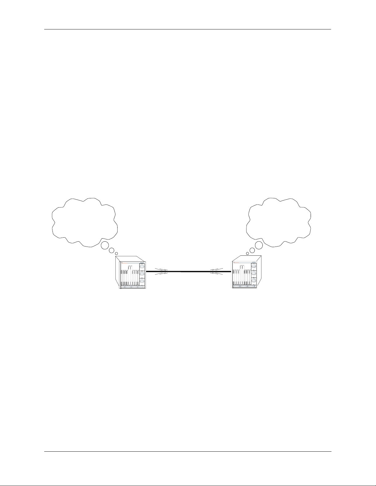
When a router starts, it uses the OSPF Hello Protocol to discover neighbors. The router sends Hello packets to its neighbors, and in turn receives their Hello packets. On broadcast and point-to-point networks, the
router dynamically detects its neighboring routers by sending Hello packets to a multicast address. On
non-broadcast and point-to-multipoint networks, some configuration information is necessary in order to
configure neighbors. On all networks (broadcast or non-broadcast), the Hello Protocol also elects a designated router for the network.
Hello. Please respond...
Are you a neighbor...
My link state is...
OmniSwitch 7700
OmniSwitch 7700
TM
TM
Hello. Please respond...
Are you a neighbor...
My link state is...
OSPF Hello Protocol
The router will attempt to form full adjacencies with all of its newly acquired neighbors. Only some pairs,
however, will be successful in forming full adjacencies. Topological databases are synchronized between
pairs of fully adjacent routers.
Adjacencies control the distribution of routing protocol packets. Routing protocol packets are sent and
received only on adjacencies. In particular, distribution of topological database updates proceeds along
adjacencies.
Link state is also advertised when a router’s state changes. A router’s adjacencies are reflected in the
contents of its link state advertisements. This relationship between adjacencies and link state allows the
protocol to detect downed routers in a timely fashion.
Link state advertisements are flooded throughout the AS. The flooding algorithm ensures that all routers
have exactly the same topological database. This database consists of the collection of link state advertisements received from each router belonging to the area. From this database each router calculates a shortest-path tree, with itself as root. This shortest-path tree in turn yields a routing table for the protocol.
OmniSwitch 7700/7800/8800 Advanced Routing Configuration Guide April 2006 page 1-7
Page 24
OSPF Overview Configuring OSPF
OSPF Areas
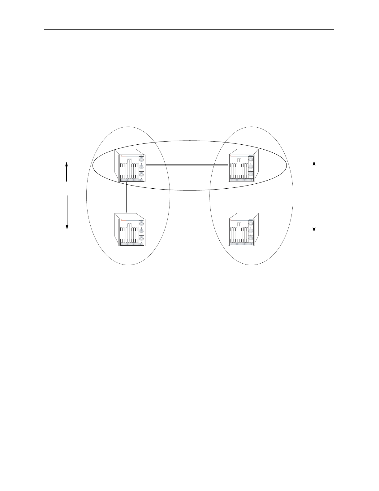
OSPF allows collections of contiguous networks and hosts to be grouped together as an area. Each area
runs a separate copy of the basic link-state routing algorithm (usually called SPF). This means that each
area has its own topological database, as explained in the previous section.
Inter-Area Routing
Intra-Area
Routing
Router 1
Link State
Messages
Router 2
OmniSwitch 7700
TM
OmniSwitch 7700
TM
Area 1
Backbone
OmniSwitch 7700
TM
OmniSwitch 7700
TM
Area 2
Intra-Area
Routing
Router 3
Link State
Messages
Router 4
OSPF Intra-Area and Inter-Area Routing
An area’s topology is visible only to the members of the area. Conversely, routers internal to a given area
know nothing of the detailed topology external to the area. This isolation of knowledge enables the protocol to reduce routing traffic by concentrating on small areas of an AS, as compared to treating the entire
AS as a single link-state domain.
Areas cause routers to maintain a separate topological database for each area to which they are connected.
(Routers connected to multiple areas are called area border routers). Two routers belonging to the same
area have identical area topological databases.
Different areas communicate with each other through a backbone. The backbone consists of routers with
contacts between multiple areas. A backbone must be contiguous (i.e., it must be linked to all areas).
The backbone is responsible for distributing routing information between areas. The backbone itself has all
of the properties of an area. The topology of the backbone is invisible to each of the areas, while the backbone itself knows nothing of the topology of the areas.
All routers in an area must agree on that area’s parameters. Since a separate copy of the link-state algorithm is run in each area, most configuration parameters are defined on a per-router basis. All routers
belonging to an area must agree on that area’s configuration. Misconfiguration will keep neighbors from
forming adjacencies between themselves, and OSPF will not function.
page 1-8 OmniSwitch 7700/7800/8800 Advanced Routing Configuration Guide April 2006
Page 25

Configuring OSPF OSPF Overview
Classification of Routers
When an AS is split into OSPF areas, the routers are further divided according to function into the following four overlapping categories:
• Internal routers. A router with all directly connected networks belonging to the same area. These
routers run a single copy of the SPF algorithm.
• Area border routers. A router that attaches to multiple areas. Area border routers run multiple copies
of the SPF algorithm, one copy for each attached area. Area border routers condense the topological
information of their attached areas for flooding to other areas.
• Backbone routers. A router that has an interface to the backbone. This includes all routers that inter-
face to more than one area (i.e., area border routers). However, backbone routers do not have to be area
border routers. Routers with all interfaces connected to the backbone are considered to be internal routers.
• AS boundary routers. A router that exchanges routing information with routers belonging to other
Autonomous Systems. Such a router has AS external routes that are advertised throughout the Autonomous System. The path to each AS boundary router is known by every router in the AS. This classification is completely independent of the previous classifications (i.e., internal, area border, and
backbone routers). AS boundary routers may be internal or area border routers, and may or may not
participate in the backbone.
Virtual Links
It is possible to define areas in such a way that the backbone is no longer contiguous. (This is not an ideal
OSPF configuration, and maximum effort should be made to avoid this situation.) In this case the system
administrator must restore backbone connectivity by configuring virtual links.
Virtual links can be configured between any two backbone routers that have a connection to a common
non-backbone area. The protocol treats two routers joined by a virtual link as if they were connected by an
unnumbered point-to-point network. The routing protocol traffic that flows along the virtual link uses
intra-area routing only, and the physical connection between the two routers is not managed by the
network administrator (i.e., there is no dedicated connection between the routers as there is with the OSPF
backbone).
Router B
OmniSwitch 7700
TM
Backbone
Backbone
Router A
OmniSwitch 7700
TM
Area 1
Virtual Link
OSPF Routers Connected with a Virtual Link
In the above diagram, Router A and Router B are connected via a virtual link in Area 1, which is known as
a transit area. See “Creating Virtual Links” on page 1-24 for more information.
OmniSwitch 7700/7800/8800 Advanced Routing Configuration Guide April 2006 page 1-9
Page 26
OSPF Overview Configuring OSPF
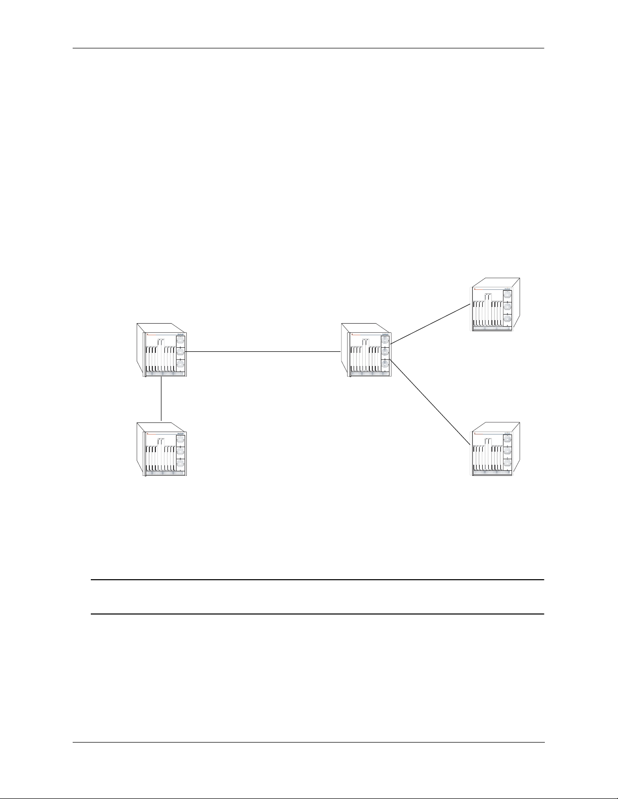
Stub Areas
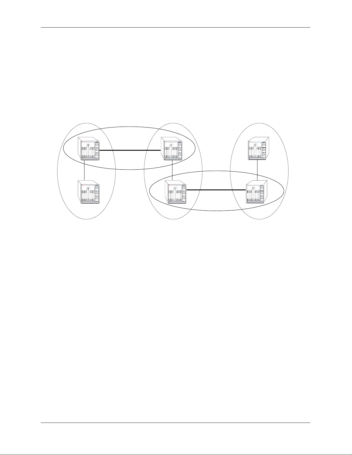
OSPF allows certain areas to be configured as stub areas. A stub area is an area with routers that have no
AS external Link State Advertisements (LSAs).
In order to take advantage of the OSPF stub area support, default routing must be used in the stub area.
This is accomplished by configuring only one of the stub area’s border routers to advertise a default route
into the stub area. The default routes will match any destination that is not explicitly reachable by an intraarea or inter-area path (i.e., AS external destinations).
OmniSwitch 7700
OmniSwitch 7700
TM
OmniSwitch 7700
TM
Backbone
OmniSwitch 7700
TM
OmniSwitch 7700
TM
TM
OmniSwitch 7700
TM
Backbone
Area 1
(stub)
Area 2
Area 3
(stub)
OSPF Stub Area
Area 1 and Area 3 could be configured as stub areas. Stub areas are configured using the OSPF ip ospf
area command, described in “Creating an Area” on page 1-17. For more overview information on areas,
see “OSPF Areas” on page 1-8.
The OSPF protocol ensures that all routers belonging to an area agree on whether the area has been configured as a stub. This guarantees that no confusion will arise in the flooding of AS external advertisements.
Two restrictions on the use of stub areas are:
• Virtual links cannot be configured through stub areas.
• AS boundary routers cannot be placed internal to stub areas.
page 1-10 OmniSwitch 7700/7800/8800 Advanced Routing Configuration Guide April 2006
Page 27

Configuring OSPF OSPF Overview
Not-So-Stubby-Areas
NSSA, or not-so-stubby area, is an extension to the base OSPF specification and is defined in RFC 1587.
An NSSA is similar to a stub area in many ways: AS-external LSAs are not flooded into an NSSA and
virtual links are not allowed in an NSSA. The primary difference is that selected external routing information can be imported into an NSSA and then redistributed into the rest of the OSPF routing domain. These
routes are imported into the NSSA using a new LSA type: Type-7 LSA. Type-7 LSAs are flooded within
the NSSA and are translated at the NSSA boundary into AS-external LSAs so as to convey the external
routing information to other areas.
NSSAs enable routers with limited resources to participate in OSPF routing while also allowing the import
of a selected number of external routes into the area. For example, an area which connects to a small
external routing domain running RIP may be configured as an NSSA. This will allow the import of RIP
routes into this area and the rest of the OSPF routing domain and at the same time, prevent the flooding of
other external routing information (learned, for example, through RIP) into this area.
All routers in an NSSA must have their OSPF area defined as an NSSA. To configure otherwise will
ensure that the router will be unsuccessful in establishing an adjacent in the OSPF domain.
Totally Stubby Areas
In Totally Stubby Areas the ABR advertises a default route to the routers in the totally stubby area but
does not advertise any inter-area or external LSAs. As a result, routers in a totally stubby area know only
the routes for destination networks in the stub area and have a default route for any other destination
outside the stub.
Note. Virtual links cannot be configured through totally stubby areas.
The router memory is saved when using stub area networks by filtering Type 4 and 5 LSAs. This concept
has been extended with Totally Stubby Areas by filtering Type 3 LSAs (Network Summary LSA) in addition to Type 4 and 5 with the exception of one single Type 3 LSA used to advertise a default route within
the area.
The following is an example of a simple totally stubby configuration with Router B being an ABR
between the backbone area 0 and the stub area 1. Router A is in area 1.1.1.1, totally stubby area:
OSPF Area 0
192.168.50.0/24
OmniSwitch 7700
OmniSwitch 7700
TM
Router A
192.168.12.1
OSPF Area 1
Totally Stubby
192.168.12.2
TM
Router B
Totally Stubby Area Example
Note. See “Configuring a Totally Stubby Area” on page 1-19 for information on configuring Totally
Stubby Areas.
OmniSwitch 7700/7800/8800 Advanced Routing Configuration Guide April 2006 page 1-11
Page 28
OSPF Overview Configuring OSPF
Equal Cost Multi-Path (ECMP) Routing
Using information from its continuously updated databases, OSPF calculates the shortest path to a given
destination. The shortest path is determined from metric values at each hop along a path. At times, two or
more paths to the same destination will have the same metric cost.
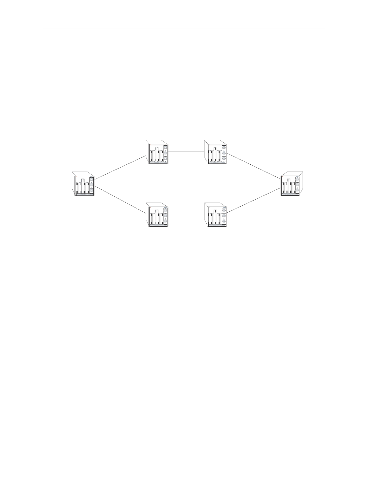
In the network illustration below, there are two paths from Source router A to Destination router B. One
path traverses two hops at routers X and Y and the second path traverses two hops at M and N. If the total
cost through X and Y to B is the same as the cost via M and N to B, then these two paths have equal cost.
In this version of OSPF both paths will be stored and used to transmit data.
XY
OmniSwitch 7700
TM
OmniSwitch 7700
TM
A-> X-> Y-> B = A-> M-> N-> B
OmniSwitch 7700
TM
OmniSwitch 7700
TM
Source (A)
OmniSwitch 7700
TM
OmniSwitch 7700
TM
Destination (B)
MN
Multiple Equal Cost Paths
Delivery of packets along equal paths is based on flows rather than a round-robin scheme. Equal cost is
determined based on standard routing metrics. However, other variables, such as line speed, are not
considered. So it is possible for OSPF to decide two paths have an equal cost even though one may contain
faster links than another.
Non-Broadcast OSPF Routing
OSPF can operate in two modes on non-broadcast networks: NBMA and point-to-multipoint. The interface type for the corresponding network segment should be set to non-broadcast or point-to-multipoint,
respectively.
For non-broadcast networks neighbors should be statically configured. For NBMA neighbors the eligibility option must be enabled for the neighboring router to participate in Designated Router (DR) election.
For the correct working of an OSPF NBMA network, a fully meshed network is mandatory. Also, the
neighbor eligibility configuration for a router on every other router should match the routers interface
priority configuration.
See “Configuring Static Neighbors” on page 1-29 for more information and setting up static neighbors.
page 1-12 OmniSwitch 7700/7800/8800 Advanced Routing Configuration Guide April 2006
Page 29
Configuring OSPF OSPF Overview
Graceful Restart on Switches with Redundant CMMs
OmniSwitch 7700/7800/8800 chassis with two Chassis Management Modules (CMMs) can support redundancy where if the primary CMM fails or goes offline for any reason, the secondary CMM is instantly
notified. The secondary CMM automatically assumes the primary role. This switch between the primary
and secondary CMMs is known as takeover.
When a takeover occurs, which can be planned (e.g., the users performs the takeover) or unplanned (e.g.,
the primary CMM unexpectedly fails), an OSPF router must re-establish full adjacencies with all its previously fully adjacent neighbors. This time period between the restart and the re-establishment of adjacencies is termed graceful restart.
In the network illustration below, a helper router, Router Y, monitors the network for topology changes.
As long as there are none, it continues to advertise its LSAs as if the restarting router, Router X, had
remained in continuous OSPF operation (i.e., Router Y’s LSAs continue to list an adjacency to Router X
over network segment S, regardless of the adjacency’s current synchronization state.)
Router B
OmniSwitch 7700
TM
Restarting Router X
OmniSwitch 7700
TM
Helping Router Y
OmniSwitch 7700
TM
Network Segment S
OmniSwitch 7700
OmniSwitch 7700
TM
Router A
TM
Router C
OSPF Graceful Restart Helping and Restarting Router Example
If the restarting router, Router X, was the Designated Router (DR) on network segment S when the helping relationship began, the helper neighbor, Router Y, maintains Router X as the DR until the helping relationship is terminated. If there are multiple adjacencies with the restarting Router X, Router Y will act as a
helper on all other adjacencies.
Note. See “Configuring Redundant CMMs for Graceful Restart” on page 1-30 for more information on
configuring graceful restart.
OmniSwitch 7700/7800/8800 Advanced Routing Configuration Guide April 2006 page 1-13
Page 30

Configuring OSPF Configuring OSPF
Configuring OSPF
Configuring OSPF on a router requires several steps. Depending on your requirements, you may not need
to perform all of the steps listed below.
By default, OSPF is disabled on the router. Configuring OSPF consists of these tasks:
• Set up the basics of the OSPF network by configuring the required VLANs, assigning ports to the
VLANs, and assigning router identification numbers to the routers involved. This is described in
“Preparing the Network for OSPF” on page 1-15.
• Enable OSPF. When the image file for advanced routing is installed, you must load the code and enable
OSPF. The commands for enabling OSPF are described in “Activating OSPF” on page 1-16.
• Create an OSPF area and the backbone. The commands to create areas and backbones are described in
“Creating an OSPF Area” on page 1-17.
• Set area parameters (optional). OSPF will run with the default area parameters, but different networks
may benefit from modifying the parameters. Modifying area parameters is described in “Configuring
Stub Area Default Metrics” on page 1-18.
• Create OSPF interfaces. OSPF interfaces are created and assigned to areas. Creating interfaces is
described in “Creating an Interface” on page 1-21, and assigning interfaces is described in “Assigning
an Interface to an Area” on page 1-21.
• Set interface parameters (optional). OSPF will run with the default interface parameters, but different
networks may benefit from modifying the parameters. Also, it is possible to set authentication on an
interface. Setting interface authentication is described in “Interface Authentication” on page 1-22, and
modifying interface parameters is described in “Modifying Interface Parameters” on page 1-23.
• Configure virtual links (optional). A virtual link is used to establish backbone connectivity when two
backbone routers are not physically contiguous. To create a virtual link, see “Creating Virtual Links”
on page 1-24.
• Create a redistribution policy (optional). A redistribution policy allows for the control of how routes
are advertised into OSPF from outside the Autonomous System. Once a policy is created, redistribution must be enabled. Creating a redistribution policy is described in “Creating A Redistribution
Policy” on page 1-26, and enabling redistribution is described in “Enabling Redistribution” on
page 1-25.
• Create redistribution filters (optional). A redistribution filter controls whether routes are advertised in
the OSPF network. Creating a redistribution filter is described in “Creating a Redistribution Filter” on
page 1-26.
• Configuring router capabilities (optional). There are several commands that influence router operation.
These are covered briefly in a table in “Configuring Router Capabilities” on page 1-28.
• Creating static neighbors (optional). These commands allow you to statically configure neighbors. See
“Configuring Static Neighbors” on page 1-29.
• Configuring redundant CMMs for graceful OSPF restart (optional). Configuring switches with redun-
dant CMMs for graceful restart is described in “Configuring Redundant CMMs for Graceful Restart”
on page 1-30.
At the end of the chapter is a simple OSPF network diagram with instructions on how it was created on a
router-by-router basis. See “OSPF Application Example” on page 1-31 for more information.
page 1-14 OmniSwitch 7700/7800/8800 Advanced Routing Configuration Guide April 2006
Page 31

Configuring OSPF Configuring OSPF
Preparing the Network for OSPF
The OSPF operates on top of normal switch functions, using existing ports, virtual ports, VLANs, etc. The
following network components should already be configured:
• Configure VLANs that are to be used in the OSPF network. VLANS should be created for both the
backbone interfaces and all other connected devices that will participate in the OSPF network. A
VLAN should exist for each instance in which the backbone connects two routers. VLAN configuration is described in “Configuring VLANs,” in the OmniSwitch 7700/7800/8800 Network Configura-
tion Guide.
• Assign IP interfaces to the VLANs. IP interfaces, or router ports, must be assigned to the VLAN.
Assigning IP interfaces is described in “Configuring VLANs,” in the OmniSwitch 7700/7800/8800
Network Configuration Guide.
• Assign ports to the VLANs. The physical ports participating in the OSPF network must be assigned to
the created VLANs. Assigning ports to a VLAN is described in “Assigning Ports to VLANs,” in the
OmniSwitch 7700/7800/8800 Network Configuration Guide.
• Set the router identification number. (optional) The routers participating in the OSPF network must
be assigned a router identification number. This number can be any number, as long as it is in standard
dotted decimal format (e.g., 1.1.1.1). Router identification number assignment is discussed in “Configuring IP,” in the OmniSwitch 7700/7800/8800 Network Configuration Guide. If this is not done, the
router identification number is automatically the primary interface address.
OmniSwitch 7700/7800/8800 Advanced Routing Configuration Guide April 2006 page 1-15
Page 32

Configuring OSPF Configuring OSPF
Activating OSPF
For OSPF to run on the router, the advanced routing image must be installed. (For information on how to
install image files, see the OmniSwitch 7700/7800/8800 Switch Management Guide.)
After the image file has been installed onto the router, you will need to load the OSPF software into
memory and enable it, as described below.
Loading the Software
To load the OSPF software into the router’s running configuration, enter the ip load ospf command at the
system prompt:
-> ip load ospf
The OPSF software is now loaded into memory, and can be enabled.
Enabling OSPF
Once the OSPF software has been loaded into the router’s running configuration (either through the CLI or
on startup), it must be enabled. To enable OSPF on a router, enter the ip ospf status command at the CLI
prompt, as shown:
-> ip ospf status enable
Once OSPF is enabled, you can begin to set up OSPF parameters. To disable OSPF, enter the following:
-> ip ospf status disable
Removing OSPF from Memory
To remove OSPF from the router memory, it is necessary to manually edit the boot.cfg file. The boot.cfg
file is an ASCII text-based file that controls many of the switch parameters. Open the file and delete all
references to OSPF.
For the operation to take effect the switch needs to be rebooted.
page 1-16 OmniSwitch 7700/7800/8800 Advanced Routing Configuration Guide April 2006
Page 33

Configuring OSPF Configuring OSPF
Creating an OSPF Area
OSPF allows a set of network devices in an AS system to be grouped together in areas.
There can be more than one router in an area. Likewise, there can be more than one area on a single router
(in effect, making the router the Area Border Router (ABR) for the areas involved), but standard networking design does not recommended that more than three areas be handled on a single router.
Areas are named using 32-bit dotted decimal format (e.g., 1.1.1.1). Area 0.0.0.0 is reserved for the backbone.
Creating an Area
To create an area and associate it with a router, enter the ip ospf area command with the area identifica-
tion number at the CLI prompt, as shown:
-> ip ospf area 1.1.1.1
Area 1.1.1.1 will now be created on the router with the default parameters.
The backbone is always area 0.0.0.0. To create this area on a router, you would use the above command,
but specify the backbone, as shown:
-> ip ospf area 0.0.0.0
The backbone would now be attached to the router, making it an Area Border Router (ABR).
Enabling an Area
Once an area is created, it must be enabled using the ip ospf area status command, as shown:
-> ip ospf area 0.0.0.0 status enable
Specifying an Area Type
When creating areas, an area type can be specified (normal, stub, or NSSA). Area types are described
above in “OSPF Areas” on page 1-8. To specify an area type, use the ip ospf area command as shown:
-> ip ospf area 1.1.1.1 type stub
Note. By default, an area is a normal area. The type keyword would be used to change a stub or NSSA
area into a normal area.
OmniSwitch 7700/7800/8800 Advanced Routing Configuration Guide April 2006 page 1-17
Page 34

Configuring OSPF Configuring OSPF
Enabling and Disabling Summarization
Summarization can also be enabled or disabled when creating an area. Enabling summarization allows for
ranges to be used by Area Border Routers (ABRs) for advertising routes as a single route rather than
multiple routes, while disabling summarization prevents set ranges from functioning in stub and NSSA
areas. (Configuring ranges is described in “Setting Area Ranges” on page 1-19.)
For example, to enable summarization for Area 1.1.1.1, enter the following:
-> ip ospf area 1.1.1.1 summary enable
To disable summarization for the same area, enter the following:
-> ip ospf area 1.1.1.1 summary disable
Note. By default, an area has summarization enabled. Disabling summarization for an area is useful when
ranges need to be deactivated, but not deleted.
Displaying Area Status
You can check the status of the newly created area by using the show command, as demonstrated:
-> show ip ospf area 1.1.1.1
or
-> show ip ospf area
The first example gives specifics about area 1.1.1.1, and the second example shows all areas configured on
the router.
To display a stub area’s parameters, use the show ip ospf area stub command as follows:
-> show ip ospf area 1.1.1.1 stub
Deleting an Area
To delete an area, enter the ip ospf area command as shown:
-> no ip ospf area 1.1.1.1
Configuring Stub Area Default Metrics
The default metric configures the type of cost metric that a default area border router (ABR) will advertise
in the default summary Link State Advertisement (LSA). Use the ip ospf area default-metric command
to create or delete a default metric for stub or Not So Stubby Area (NSSA) area. Specify the stub area and
select a cost value or a route type, as shown:
-> ip ospf area 1.1.1.1 default-metric 0 cost 50
or
-> ip ospf area 1.1.1.1 default-metric 0 type type1
page 1-18 OmniSwitch 7700/7800/8800 Advanced Routing Configuration Guide April 2006
Page 35

Configuring OSPF Configuring OSPF
A route has a preset metric associated to it depending on its type. The first example, the stub area is given
a default metric of 0 (this is Type of Service 0) and a cost of 50 added to routes from the area. The second
example specifies that the cost associated with Type 1 routes should be applied to routes from the area.
Note. At this time, only the default metric of ToS 0 is supported.
To remove the area default-metric setting, enter the ip ospf area default-metric command using the no
command, as shown:
-> no ip ospf area 1.1.1.1 default-metric 0
Setting Area Ranges
Area ranges are used to summarize many area routes into a single advertisement at an area boundary.
Ranges are advertised as summaries or NSSAs. Ranges also act as filters that either allow the summary to
be advertised or not. Ranges are created using the ip ospf area range command. An area and the summary
IP address and IP mask must be specified. For example, to create a summary range with IP address
192.5.40.1 and an IP mask of 255.255.255.0 for area 1.1.1.1, the following commands would be entered at
the CLI prompt:
-> ip ospf area 1.1.1.1 range summary 192.5.40.1 255.255.255.0
-> ip ospf area 1.1.1.1 range summary 192.5.40.1 255.255.255.0 effect noMatching
To view the configured ranges for an area, use the show ip ospf area range command as demonstrated:
-> show ip ospf area 1.1.1.1 range
Configuring a Totally Stubby Area
In order to configure a totally stubby area you need to configure the area as stub on the ABR and disable
summarization. By doing so the ABR will generate a default route in the totally stubby area. In addition,
the other routers within the totally stubby area must only have their area configured as stub.
For example, to configure the simple totally stubby configuration shown in the figure in “Totally Stubby
Areas” on page 1-11 where Router B is an ABR between the backbone area 0 and the stub area 1 and
Router A is in Totally Stubby Area 1.1.1.1 follow the steps below:
1 Enter the following commands on Router B:
-> ip load ospf
-> ip ospf area 0.0.0.0
-> ip ospf area 0.0.0.0 status enable
-> ip ospf area 1.1.1.1
-> ip ospf area 1.1.1.1 type stub
-> ip ospf area 1.1.1.1 summary disable
-> ip ospf area 1.1.1.1 status enable
-> ip ospf area 1.1.1.1 default-metric 0
-> ip ospf interface 192.168.12.2
-> ip ospf interface 192.168.12.2 area 1.1.1.1
-> ip ospf interface 192.168.12.2 status enable
-> ip ospf interface 192.168.50.2
-> ip ospf interface 192.168.50.2 area 0.0.0.0
-> ip ospf interface 192.168.50.2 status enable
-> ip ospf status enable
OmniSwitch 7700/7800/8800 Advanced Routing Configuration Guide April 2006 page 1-19
Page 36

Configuring OSPF Configuring OSPF
2 Enter the following on Router A:
-> ip load ospf
-> ip ospf area 1.1.1.1
-> ip ospf area 1.1.1.1 type stub
-> ip ospf area 1.1.1.1 status enable
-> ip ospf interface 192.168.12.1
-> ip ospf interface 192.168.12.1 area 1.1.1.1
-> ip ospf interface 192.168.12.1 status enable
-> ip ospf status enable
page 1-20 OmniSwitch 7700/7800/8800 Advanced Routing Configuration Guide April 2006
Page 37

Configuring OSPF Configuring OSPF
Creating OSPF Interfaces
Once areas have been established, interfaces need to be created and assigned to the areas.
Creating an Interface
To create an interface, enter the ip ospf interface command with an IP address or interface name, as
shown:
-> ip ospf interface 120.5.80.1
-> ip ospf interface vlan-213
Note. The interface name cannot have spaces.
The interface can be deleted the by using the no keyword, as shown:
-> no ip ospf interface 120.5.80.1
Assigning an Interface to an Area
Once an interface is created, it must be assigned to an area. (Creating areas is described in “Creating an
Area” on page 1-17 above.)
To assign an interface to an area, enter the ip ospf interface area command with the interface IP address
or interface name and area identification number at the CLI prompt. For example to add interface
120.5.80.1 to area 1.1.1.1, enter the following:
-> ip ospf interface 120.5.80.1 area 1.1.1.1
An interface can be removed from an area by reassigning it to a new area.
Once an interface has been created and enabled, you can check its status and configuration by using the
show ip ospf interface command, as demonstrated:
-> show ip ospf interface 120.5.80.1
Instructions for configuring authentication are given in “Interface Authentication” on page 1-22, and interface parameter options are described in “Modifying Interface Parameters” on page 1-23.
Activating an Interface
Once the interface is created and assigned to an area, it must be activated using the ip ospf interface
status command with the interface IP address or interface name, as shown:
-> ip ospf interface 120.5.80.1 status enable
The interface can be disabled using the disable keyword in place of the enable keyword.
OmniSwitch 7700/7800/8800 Advanced Routing Configuration Guide April 2006 page 1-21
Page 38

Configuring OSPF Configuring OSPF
Interface Authentication
OSPF allows for the use of authentication on configured interfaces. When authentication is enabled, only
neighbors using the same type of authentication and the matching passwords or keys can communicate.
There are two types of authentication: simple and MD5. Simple authentication requires only a text string
as a password, while MD5 is a form of encrypted authentication that requires a key and a password. Both
types of authentication require the use of more than one command.
Simple Authentication
To enable simple authentication on an interface, enter the ip ospf interface auth-type command with the
interface IP address or interface name, as shown:
-> ip ospf interface 120.5.80.1 auth-type simple
Once simple authentication is enabled, the password must be set with the ip ospf interface auth-key
command, as shown:
-> ip ospf interface 120.5.80.1 auth-key test
In the above instance, only other interfaces with simple authentication and a password of “test” will be
able to use the configured interface.
MD5 Encryption
To configure the same interface for MD5 encryption, enter the ip ospf interface auth-type as shown:
-> ip ospf interface 120.5.80.1 auth-type md5
Once MD5 authentication is set, a key identification and key string must be set with the ip ospf interface
md5 key command. For example to set interface 120.5.80.1 to use MD5 authentication with a key identifi-
cation of 7 and key string of “test”, enter:
-> ip ospf interface 120.5.80.1 md5 7
and
-> ip ospf interface 120.5.80.1 md5 7 key "test"
Note that setting the key ID and key string must be done in two separate commands. Once the key ID and
key string have been set, MD5 authentication is enabled. To disable it, use the ip ospf interface md5
command, as shown:
-> ip ospf interface 120.5.80.1 md5 7 disable
To remove all authentication, enter the ip ospf interface auth-type as follows:
-> ip ospf interface 120.5.80.1 auth-type none
page 1-22 OmniSwitch 7700/7800/8800 Advanced Routing Configuration Guide April 2006
Page 39

Configuring OSPF Configuring OSPF
Modifying Interface Parameters
There are several interface parameters that can be modified on a specified interface. Most of these deal
with timer settings.
The cost parameter and the priority parameter help to determine the cost of the route using this interface,
and the chance that this interface’s router will become the designated router, respectively.
The following table shows the various interface parameters that can be set:
ip ospf interface dead-interval Configures OSPF interface dead interval. If no hello packets are
received in this interval from a neighboring router the neighbor is considered dead.
ip ospf interface hello-interval Configures the OSPF interface interval for NBMA segments.
ip ospf interface cost Configures the OSPF interface cost. A cost metric refers to the net-
work path preference assigned to certain types of traffic.
ip ospf interface poll-interval Configures the OSPF poll interval.
ip ospf interface priority Configures the OSPF interface priority. The priority number helps
determine if this router will become the designated router.
ip ospf interface retrans-interval Configures OSPF interface retransmit interval. The number of sec-
onds between link state advertisement retransmissions for adjacencies
belonging to this interface.
ip ospf interface transit-delay Configures the OSPF interface transit delay. The estimated number of
seconds required to transmit a link state update over this interface.
These parameters can be added any time. (See “Creating OSPF Interfaces” on page 1-21 for more information.) For example, to set an the dead interval to 50 and the cost to 100 on interface 120.5.80.1, enter
the following:
-> ip ospf interface 120.5.80.1 dead-interval 50 cost 100
To set an the poll interval to 25, the priority to 100, and the retransmit interval to 10 on interface
120.5.80.1, enter the following:
-> ip ospf interface 120.5.80.1 poll-interval 25 priority 100 retrans-interval
10
To set the hello interval to 5000 on interface 120.5.80.1, enter the following:
-> ip ospf interface 120.5.80.1 hello-interval 5000
To reset any parameter to its default value, enter the keyword with no parameter value, as shown:
-> ip ospf interface 120.5.80.1 dead-interval
Note. Although you can configure several parameters at once, you can only reset them to the default one
at a time.
OmniSwitch 7700/7800/8800 Advanced Routing Configuration Guide April 2006 page 1-23
Page 40

Configuring OSPF Configuring OSPF
Creating Virtual Links
A virtual link is a link between two backbones through a transit area. Use the ip ospf virtual-link
command to create or delete a virtual link.
Accepted network design theory states that virtual links are the option of last resort. For more information
on virtual links, see “Virtual Links” on page 1-9 and refer to the figure on page 1-9.
Creating a Virtual Link
To create a virtual link, commands must be submitted to the routers at both ends of the link. The router
being configured should point to the other end of the link, and both routers must have a common area.
When entering the ip ospf virtual-link command, it is necessary to enter the Router ID of the far end of
the link, and the area ID that both ends of the link share.
For example, a virtual link needs to be created between Router A (router ID 1.1.1.1) and Router B (router
ID 2.2.2.2). We must:
1 Establish a transit area between the two routers using the commands discussed in “Creating an OSPF
Area” on page 1-17 (in this example, we will use Area 0.0.0.1).
2 Then use the ip ospf virtual-link command on Router A as shown:
ip ospf virtual-link 0.0.0.1 2.2.2.2
3 Next, enter the following command on Router B:
ip ospf virtual-link 0.0.0.1 1.1.1.1
Now there is a virtual link across Area 0.0.0.1 linking Router A and Router B.
4 To display virtual links configured on a router, enter the following show command:
show ip ospf virtual-link
5 To delete a virtual link, enter the ip ospf virtual-link command with the area and far end router infor-
mation, as shown:
no ip ospf virtual-link 0.0.0.1 2.2.2.2
Modifying Virtual Link Parameters
There are several parameters for a virtual link (such as authentication type and cost) that can be modified
at the time of the link creation. They are described in the ip ospf virtual-link command description.These
parameters are identical in function to their counterparts in the section “Modifying Interface Parameters”
on page 1-23.
page 1-24 OmniSwitch 7700/7800/8800 Advanced Routing Configuration Guide April 2006
Page 41

Configuring OSPF Configuring OSPF
Creating Redistribution Policies and Filters
Redistribution in OSPF controls the way routes are learned and distributed in the OSPF network. NonOSPF routers can be advertised into the OSPF network as AS-external or NSSA-external routes. NSSAexternal routes are advertised only in OSPF-NSSA areas. Redistribution policies are set on Autonomous
System Boundary Routers (ASBRs) and control how routes from outside the Autonomous System (AS)
are learned and distributed. Redistribution Filters are set on any OSPF router and control how routes on
the router are distributed to other routers in the OSPF network.
To set up redistribution on a router:
1 Specify the router as an ASBR, as described in “Specifying an Autonomous System Boundary Router”
on page 1-25. (For redistribution policies only.)
2 Enable redistribution, as described in “Enabling Redistribution” on page 1-25.
3 Create a redistribution policy or filter, as described in “Creating A Redistribution Policy” on page 1-26
and “Creating a Redistribution Filter” on page 1-26.
Specifying an Autonomous System Boundary Router
Redistribution policies can only be created on ASBRs. ASBRs are routers that are directly connected to a
network outside of the AS (e.g., the internet). To configure a router to be an ASBR, enter the ip ospf asbr
command at the CLI prompt, as shown:
-> ip ospf asbr
You can check to see if a router is an ASBR router by using the show ip ospf command.
Enabling Redistribution
Before using any type of redistribution policy or filter, you must enable redistribution on the router, using
the ip ospf redist status command. To enable redistribution, enter the command at the CLI prompt as
shown:
-> ip ospf redist status enable
To disable redistribution, enter the command as shown:
-> ip ospf redist status disable
OmniSwitch 7700/7800/8800 Advanced Routing Configuration Guide April 2006 page 1-25
Page 42

Configuring OSPF Configuring OSPF
Creating A Redistribution Policy
Once a router is set as an ASBR and redistribution is enabled, a redistribution policy can be created. This
is done using the ip ospf redist command. When setting up a redistribution policy, choose the type of
route or protocol that will be redistributed as an OSPF route in the OSPF network. For example, to redistribute RIP routes, enter the following:
-> ip ospf redist rip
To redistribute static routes, enter the following:
-> ip ospf redist static
A cost metric can be added to the redistributed route, either as a set number or by specifying a route type
(route types have preassigned metrics and other rule that control how they are redistributed). For example,
to add a cost metric of 50 to RIP routes, enter the following:
-> ip ospf redist rip metric 50
To set RIP route redistribution as type 1 routes, enter the following:
-> ip ospf redist rip metric-type type1
For more information on route types, see the ip ospf redist command in the OmniSwitch CLI Reference
Guide.
To display the redistribution policies on a router, enter the show ip ospf redist command at the CLI
prompt.
To delete a redistribution policy, enter the ip ospf redist command with the route or protocol type, and the
no keyword, as shown:
-> no ip ospf redist rip
Creating a Redistribution Filter
Redistribution filters are used by routers to control which routes are advertised to the rest of the network.
Filters can be created on any OSPF router that has redistribution enabled.
Filters are created using the ip ospf redist-filter command.When using a filter, a route or protocol type
must be specified, along with the IP address and mask. Only routes matching the specified criteria will be
advertised. For example, to create a filter for RIP routes 1.1.0.0 with a mask of 255.255.0.0, enter the
following:
-> ip ospf redist-filter rip 1.1.0.0 255.255.0.0
Filters can also be used to prevent routes from being advertised by using the effect keyword. Using the
above example, to prevent RIP routes learned from 1.1.0.0 being advertised, enter the following:
-> ip ospf redist-filter rip 1.1.0.0 255.255.0.0 effect deny
This filter would stop the advertisement of RIP routes learned within the range 1.1.0.0 with a mask of
255.255.0.0. All other routes would be advertised normally.
Note. By default, filters are set to permit. If permit is the filter action desired, it is not necessary to use
the effect keyword.
page 1-26 OmniSwitch 7700/7800/8800 Advanced Routing Configuration Guide April 2006
Page 43

Configuring OSPF Configuring OSPF
In certain cases, redistribution can either be an adjacent route or a subnet. In these cases, the redistributed
route can correspond to several routes. It is possible to advertise these routes separately or not with the
redist-control keyword.
If it is desired to advertise only an aggregated route instead of all the routes to comprise the aggregate, use
the ip ospf redist-filter command with the redist-control aggregate keyword, as shown (you will also
need to enter the route information as above):
-> ip ospf redist-filter rip 1.1.0.0 255.255.0.0 redist-control aggregate
If it is desired that the subnet routes that fall within the aggregate range should not be advertised, use the
ip ospf redist-filter command with the redist-control keyword as shown (you will also need to enter the
route information as above):
-> ip ospf redist-filter rip 1.1.0.0 255.255.0.0 redist-control no-subnets
Note. By default, filters are set to allow subnet routes to be advertised. If this is the filter action desired, it
is not necessary to use the redist-control keyword.
A cost metric and route tag can be assigned to the routes that are allowed to pass through the filter, by
using the metric and route-tag keywords, as shown (these options are described in the ip ospf redist-
filter command):
-> ip ospf redist-filter rip 1.1.0.0 255.255.0.0 metric 100 route-tag 5
To display all of the configured filters on a router, enter the show ip ospf redist-filter command as
shown:
-> show ip ospf redist-filter
To display the configured filters for a specific route or protocol type, enter the show command and the
route or protocol type:
-> show ip ospf redist-filter rip
To display a specific filter, enter the show command with the route or protocol type and the ip address and
mask, as demonstrated:
-> show ip ospf redist-filter rip 1.1.0.0 255.255.0.0
To delete a redistribution filter, enter the ip ospf redist-filter command with the route or protocol type
and its associated IP address and mask, as shown:
-> no ip ospf redist-filter rip 1.1.0.0 255.255.0.0
OmniSwitch 7700/7800/8800 Advanced Routing Configuration Guide April 2006 page 1-27
Page 44

Configuring OSPF Configuring OSPF
Configuring Router Capabilities
The following list shows various commands that can be useful in tailoring a router’s performance capabilities. All of the listed parameters have defaults that are acceptable for running an OSPF network.
ip ospf exit-overflow-interval Sets the overflow interval value. The overflow interval is the time
whereby the router will wait before attempting to leave the database
overflow state.
ip ospf extlsdb-limit Sets a limit to the number of external Link State Databases entries
learned by the router. An external LSDB entry is created when the
router learns a link address that exists outside of its Autonomous System
(AS).
ip ospf host Creates and deletes an OSPF entry for directly attached hosts.
ip ospf mtu-checking Enables or disables the use of Maximum Transfer Unit (MTU) checking
on received OSPF database description packets.
ip ospf route-tag Configures a tag value for Autonomous System External (ASE) routes
created.
ip ospf spf-timer Configures timers for Shortest Path First (SPF) calculation.
To configure a router parameter, enter the parameter at the CLI prompt with the new value or required
variables. For example to set the exit overflow interval to 40, enter:
-> ip ospf exit-overflow-interval 40
To enable MTU checking, enter:
-> ip ospf mtu-checking
To set the route tag to 5, enter:
-> ip ospf route-tag 5
To set the SPF timer delay to 3 and the hold time to 6, enter:
-> ip ospf spf-timer delay 3 hold 6
To return a parameter to its default setting, enter the command with no parameter value, as shown:
-> ip ospf spf-timer
page 1-28 OmniSwitch 7700/7800/8800 Advanced Routing Configuration Guide April 2006
Page 45

Configuring OSPF Configuring OSPF
Configuring Static Neighbors
It is possible to configure neighbors statically on Non-Broadcast Multi Access (NBMA), point-to-point,
and point-to-multipoint networks.
NBMA requires all routers attached to the network to communicate directly (unicast), and every attached
router in this network becomes aware of all of its neighbors through configuration. It also requires a
Designated Router (DR) “eligibility” flag to be set for every neighbor.
To set up a router to use NBMA routing, follow the following steps:
1 Create an OSPF interface using the CLI command ip ospf interface and perform all the normal config-
uration for the interface as with broadcast networks (attaching it to an area, enabling the status, etc.).
2 The OSPF interface type for this interface should be set to non-broadcast using the CLI
ip ospf interface type command. For example, to set interface 1.1.1.1 to be an NBMA interface, enter the
following:
-> ip ospf interface 1.1.1.1 type non-broadcast
3 Configure static neighbors for every OSPF router in the network using the ip ospf neighbor command.
For example, to create an OSPF neighbor with an IP address of 1.1.1.8 to be a static neighbor, enter the
following:
-> ip ospf neighbor 1.1.1.8 eligible
The neighbor attaches itself to the right interface by matching the network address of the neighbor and the
interface. If the interface has not yet been created, the neighbor gets attached to the interface as and when
the interface comes up.
If this neighbor is not required to participate in DR election, configure it as non-eligible. The eligibility
can be changed at any time as long as the interface it is attached to is in the disabled state.
OmniSwitch 7700/7800/8800 Advanced Routing Configuration Guide April 2006 page 1-29
Page 46

Configuring OSPF Configuring OSPF
Configuring Redundant CMMs for Graceful Restart
By default, OSPF graceful restart is disabled. To configure OSPF graceful restart support use the ip ospf
restart-support command by entering ip ospf restart-support followed by either planned-unplanned or
planned-only.
For example, to modify OSPF graceful restart so that it only supports planned restarts enter:
-> ip ospf restart-support planned-only
To disable support for graceful restart use the no form of the ip ospf restart-support command by entering:
-> no ip ospf restart-support
Optionally, you can configure graceful restart parameters with the following CLI commands:
ip ospf restart-interval Configures the grace period for achieving a graceful OSPF restart.
ip ospf restart-helper status Administratively enables and disables the capability of an OSPF router
to operate in helper mode in response to a router performing a graceful
restart.
ip ospf restart-helper strict-lsachecking-status
ip ospf restart initiate Initiates a planned graceful restart.
Administratively enables and disables whether or not a changed Link
State Advertisement (LSA) will result in termination of graceful restart
by a helping router.
For more information about graceful restart commands, see the “OSPF Commands” chapter in the
OmniSwitch CLI Reference Guide.
page 1-30 OmniSwitch 7700/7800/8800 Advanced Routing Configuration Guide April 2006
Page 47

Configuring OSPF OSPF Application Example
OSPF Application Example
This section will demonstrate how to set up a simple OSPF network. It uses three routers, each with an
area. Each router uses three VLANs. A backbone connects all the routers. This section will demonstrate
how to set it up by explaining the necessary commands for each router.
The following diagram is a simple OSPF network. It will be created by the steps listed on the following
pages.
VLAN 10
Interface 10.0.0.1
Area 0.0.0.1
Router 1
Router ID 1.1.1.1
OmniSwitch 7700
TM
VLAN 12
Interface 12.x.x.x
OmniSwitch 7700
TM
Area 0.0.0.2
Router 2
Router ID 20.0.0.1
VLAN 20
Interface 20.0.0.1
Backbone Area
(Area 0.0.0.0)
VLAN 23
Interface 23.x.x.x
VLAN 31
Interface 31.x.x.x
OmniSwitch 7700
TM
Area 0.0.0.3
Router ID 3.3.3.3
VLAN 30
Interface 30.0.0.1
Router 3
Three Area OSPF Network
OmniSwitch 7700/7800/8800 Advanced Routing Configuration Guide April 2006 page 1-31
Page 48

OSPF Application Example Configuring OSPF
Step 1: Prepare the Routers
The first step is to create the VLANs on each router, add an IP interface to the VLAN, assign a port to the
VLAN, and assign a router identification number to the routers. For the backbone, the network design in
this case uses slot 2, port 1 as the egress port and slot 2, port 2 as ingress port on each router. Router 1
connects to Router 2, Router 2 connects to Router 3, and Router 3 connects to Router 1 using 10/100
Ethernet cables.
Note. The ports will be statically assigned to the router, as a VLAN must have a physical port assigned to
it in order for the router port to function. However, the router could be set up in such a way that mobile
ports are dynamically assigned to VLANs using VLAN rules. See the chapter titled “Defining VLAN
Rules” in the OmniSwitch 7700/7800/8800 Network Configuration Guide.
The commands setting up VLANs are shown below:
Router 1 (using ports 2/1 and 2/2 for the backbone, and ports 2/3-5 for end devices):
-> vlan 31
-> ip interface vlan-31 vlan 31 address 31.0.0.1 mask 255.0.0.0
-> vlan 31 port default 2/1
-> vlan 12
-> ip interface vlan-12 vlan 12 address 12.0.0.1 mask 255.0.0.0
-> vlan 12 port default 2/2
-> vlan 10
-> ip interface vlan-10 vlan 10 address 10.0.0.1 mask 255.0.0.0
-> vlan 10 port default 2/3-5
-> ip router router-id 1.1.1.1
These commands created VLANs 31, 12, and 10.
• VLAN 31 handles the backbone connection from Router 1 to Router 3, using the IP router port 31.0.0.1
and physical port 2/1.
• VLAN 12 handles the backbone connection from Router 1 to Router 2, using the IP router port 12.0.0.1
and physical port 2/2.
• VLAN 10 handles the device connections to Router 1, using the IP router port 10.0.0.1 and physical
ports 2/3-5. More ports could be added at a later time if necessary.
The router was assigned the Router ID of 1.1.1.1.
page 1-32 OmniSwitch 7700/7800/8800 Advanced Routing Configuration Guide April 2006
Page 49

Configuring OSPF OSPF Application Example
Router 2 (using ports 2/1 and 2/2 for the backbone, and ports 2/3-5 for end devices):
-> vlan 12
-> ip interface vlan-12 vlan 12 address 12.0.0.2 mask 255.0.0.0
-> vlan 12 port default 2/1
-> vlan 23
-> ip interface vlan-23 vlan 23 address 23.0.0.2 mask 255.0.0.0
-> vlan 23 port default 2/2
-> vlan 20
-> ip interface vlan-20 vlan 20 address 20.0.0.2 mask 255.0.0.0
-> vlan 20 port default 2/3-5
-> ip router router-id 2.2.2.2
These commands created VLANs 12, 23, and 20.
• VLAN 12 handles the backbone connection from Router 1 to Router 2, using the IP router port
12.0.0.2 and physical port 2/1.
• VLAN 23 handles the backbone connection from Router 2 to Router 3, using the IP router port
23.0.0.2 and physical port 2/2.
• VLAN 20 handles the device connections to Router 2, using the IP router port 20.0.0.2 and physical
ports 2/3-5. More ports could be added at a later time if necessary.
The router was assigned the Router ID of 2.2.2.2.
Router 3 (using ports 2/1 and 2/2 for the backbone, and ports 2/3-5 for end devices)
-> vlan 23
-> ip interface vlan-23 vlan 23 address 23.0.0.3 mask 255.0.0.0
-> vlan 23 port default 2/1
-> vlan 31
-> ip interface vlan-31 vlan 31 address 31.0.0.3 mask 255.0.0.0
-> vlan 31 port default 2/2
-> vlan 30
-> ip interface vlan-30 vlan 30 address 30.0.0.3 mask 255.0.0.0
-> vlan 30 port default 2/3-5
-> ip router router-id 3.3.3.3
These commands created VLANs 23, 31, and 30.
• VLAN 23 handles the backbone connection from Router 2 to Router 3, using the IP router port
23.0.0.3 and physical port 2/1.
• VLAN 31 handles the backbone connection from Router 3 to Router 1, using the IP router port
31.0.0.3 and physical port 2/2.
• VLAN 30 handles the device connections to Router 3, using the IP router port 30.0.0.3 and physical
ports 2/3-5. More ports could be added at a later time if necessary.
The router was assigned the Router ID of 3.3.3.3.
OmniSwitch 7700/7800/8800 Advanced Routing Configuration Guide April 2006 page 1-33
Page 50

OSPF Application Example Configuring OSPF
Step 2: Enable OSPF
The next step is to load and enable OSPF on each router. The commands for this step are below (the
commands are the same on each router):
-> ip load ospf
-> ip ospf status enable
Step 3: Create and Enable the Areas and Backbone
Now the areas should be created and enabled. In this case, we will create an area for each router, and a
backbone (area 0.0.0.0) that connects the areas.
The commands for this step are below:
Router 1
-> ip ospf area 0.0.0.0
-> ip ospf area 0.0.0.0 status enable
-> ip ospf area 0.0.0.1
-> ip ospf area 0.0.0.1 status enable
These commands created area 0.0.0.0 (the backbone) and area 0.0.0.1 (the area for Router 1). Both of
these areas are also enabled.
Router 2
-> ip ospf area 0.0.0.0
-> ip ospf area 0.0.0.0 status enable
-> ip ospf area 0.0.0.2
-> ip ospf area 0.0.0.2 status enable
These commands created Area 0.0.0.0 (the backbone) and Area 0.0.0.2 (the area for Router 2). Both of
these areas are also enabled.
Router 3
-> ip ospf area 0.0.0.0
-> ip ospf area 0.0.0.0 status enable
-> ip ospf area 0.0.0.3
-> ip ospf area 0.0.0.3 status enable
These commands created Area 0.0.0.0 (the backbone) and Area 0.0.0.3 (the area for Router 3). Both of
these areas are also enabled.
page 1-34 OmniSwitch 7700/7800/8800 Advanced Routing Configuration Guide April 2006
Page 51

Configuring OSPF OSPF Application Example
Step 4: Create, Enable, and Assign Interfaces
Next, OSPF interfaces must be created, enabled, and assigned to the areas. The OSPF interfaces should
have the same IP address as the IP router ports created above in “Step 1: Prepare the Routers” on
page 1-32.
Router 1
-> ip ospf interface 31.0.0.1
-> ip ospf interface 31.0.0.1 area 0.0.0.0
-> ip ospf interface 31.0.0.1 status enable
-> ip ospf interface 12.0.0.1
-> ip ospf interface 12.0.0.1 area 0.0.0.0
-> ip ospf interface 12.0.0.1 status enable
-> ip ospf interface 10.0.0.1
-> ip ospf interface 10.0.0.1 area 0.0.0.1
-> ip ospf interface 10.0.0.1 status enable
IP router port 31.0.0.1 was associated to OSPF interface 31.0.0.1, enabled, and assigned to the backbone.
IP router port 12.0.0.1 was associated to OSPF interface 12.0.0.1, enabled, and assigned to the backbone.
IP router port 10.0.0.1 which connects to end stations and attached network devices, was associated to
OSPF interface 10.0.0.1, enabled, and assigned to Area 0.0.0.1.
Alternatively, you can also configure Router 1 with the interface name instead of the IP address as shown
below:
-> ip ospf interface vlan-12
-> ip ospf interface vlan-12 area 0.0.0.0
-> ip ospf interface vlan-12 status enable
-> ip ospf interface vlan-12
-> ip ospf interface vlan-12 area 0.0.0.0
-> ip ospf interface vlan-12 status enable
-> ip ospf interface vlan-10
-> ip ospf interface vlan-10 area 0.0.0.1
-> ip ospf interface vlan-10 status enable
Router 2
-> ip ospf interface 12.0.0.2
-> ip ospf interface 12.0.0.2 area 0.0.0.0
-> ip ospf interface 12.0.0.2 status enable
-> ip ospf interface 23.0.0.2
-> ip ospf interface 23.0.0.2 area 0.0.0.0
-> ip ospf interface 23.0.0.2 status enable
-> ip ospf interface 20.0.0.2
-> ip ospf interface 20.0.0.2 area 0.0.0.2
-> ip ospf interface 20.0.0.2 status enable
IP router port 12.0.0.2 was associated to OSPF interface 12.0.0.2, enabled, and assigned to the backbone.
IP router port 23.0.0.2 was associated to OSPF interface 23.0.0.2, enabled, and assigned to the backbone.
IP router port 20.0.0.2, which connects to end stations and attached network devices, was associated to
OSPF interface 20.0.0.2, enabled, and assigned to Area 0.0.0.2.
OmniSwitch 7700/7800/8800 Advanced Routing Configuration Guide April 2006 page 1-35
Page 52

OSPF Application Example Configuring OSPF
Alternatively, you can also configure Router 2 with the interface name instead of the IP address as shown
below:
-> ip ospf interface vlan-12
-> ip ospf interface vlan-12 area 0.0.0.0
-> ip ospf interface vlan-12 status enable
-> ip ospf interface vlan-23
-> ip ospf interface vlan-23 area 0.0.0.0
-> ip ospf interface vlan-23 status enable
-> ip ospf interface vlan-20
-> ip ospf interface vlan-20 area 0.0.0.2
-> ip ospf interface vlan-20 status enable
Router 3
-> ip ospf interface 23.0.0.3
-> ip ospf interface 23.0.0.3 area 0.0.0.0
-> ip ospf interface 23.0.0.3 status enable
-> ip ospf interface 31.0.0.3
-> ip ospf interface 31.0.0.3 area 0.0.0.0
-> ip ospf interface 31.0.0.3 status enable
-> ip ospf interface 30.0.0.3
-> ip ospf interface 30.0.0.3 area 0.0.0.3
-> ip ospf interface 30.0.0.3 status enable
IP router port 23.0.0.3 was associated to OSPF interface 23.0.0.3, enabled, and assigned to the backbone.
IP router port 31.0.0.3 was associated to OSPF interface 31.0.0.3, enabled, and assigned to the backbone.
IP router port 30.0.0.3, which connects to end stations and attached network devices, was associated to
OSPF interface 30.0.0.3, enabled, and assigned to Area 0.0.0.3.
Alternatively, you can also configure Router 3 with the interface name instead of the IP address as shown
below:
-> ip ospf interface vlan-23
-> ip ospf interface vlan-23 area 0.0.0.0
-> ip ospf interface vlan-23 status enable
-> ip ospf interface vlan-31
-> ip ospf interface vlan-31 area 0.0.0.0
-> ip ospf interface vlan-31 status enable
-> ip ospf interface vlan-30
-> ip ospf interface vlan-30 area 0.0.0.3
-> ip ospf interface vlan-30 status enable
page 1-36 OmniSwitch 7700/7800/8800 Advanced Routing Configuration Guide April 2006
Page 53

Configuring OSPF OSPF Application Example
Step 5: Examine the Network
After the network has been created, you can check various aspects of it using show commands:
• For OSPF in general, use the show ip ospf command.
• For areas, use the show ip ospf area command.
• For interfaces, use the show ip ospf interface command.
• To check for adjacencies formed with neighbors, use the show ip ospf neighbor command.
• For routes, use the show ip ospf routes command.
OmniSwitch 7700/7800/8800 Advanced Routing Configuration Guide April 2006 page 1-37
Page 54

Verifying OSPF Configuration Configuring OSPF
Verifying OSPF Configuration
To display information about areas, interfaces, virtual links, redistribution, or OPSF in general, use the
show commands listed in the following table:
show ip ospf Displays OSPF status and general configuration parameters.
show ip ospf border-routers Displays information regarding all or specified border routers.
show ip ospf ext-lsdb Displays external Link State Advertisements from the areas to which the
router is attached.
show ip ospf host Displays information on directly attached hosts.
show ip ospf lsdb Displays LSAs in the Link State Database associated with each area.
show ip ospf neighbor Displays information on OSPF non-virtual neighbor routers
show ip ospf redist-filter Displays OSPF redistribution filter attributes.
show ip ospf redist Displays the specified redistribution instance that allows routes to be
redistributed into OSPF.
show ip ospf routes Displays OSPF routes known to the router.
show ip ospf virtual-link Displays virtual link information.
show ip ospf virtual-neighbor Displays OSPF virtual neighbors.
show ip ospf area Displays either all OSPF areas, or a specified OSPF area.
show ip ospf area range Displays all or specified configured area address range summaries for
the given area.
show ip ospf area stub Displays stub area status.
show ip ospf interface Displays OSPF interface information.
show ip ospf restart Displays the OSPF graceful restart related configuration and status.
For more information about the resulting displays form these commands, see the “OSPF Commands”
chapter in the OmniSwitch CLI Reference Guide.
Examples of the show ip ospf, show ip ospf area, and show ip ospf interface command outputs are given
in the section “OSPF Quick Steps” on page 1-4.
page 1-38 OmniSwitch 7700/7800/8800 Advanced Routing Configuration Guide April 2006
Page 55

2 Configuring BGP
The Border Gateway Protocol (BGP) is an exterior routing protocol that guarantees the loop-free exchange
of routing information between autonomous systems. The Alcatel implementation supports BGP version
as defined in RFC 1771.
The Alcatel implementation of BGP is designed for enterprise networks, specifically for border routers
handling a public network connection, such as the organization’s Internet Service Provider (ISP) link. Up
to 65,000 route table entries and next hop routes can be supported by BGP.
This chapter describes the configuration and use of BGP using the Command Line Interface (CLI). CLI
commands are used in the configuration examples in this chapter. For more details about the syntax of
these commands, see the OmniSwitch CLI Reference Guide.
Note. In the following document, the BGP terms “peer” and “neighbor” are used interchangeably.
In This Chapter
4
The topics and configuration procedures in this chapter include:
• Setting up global BGP parameters, such as a router’s Autonomous System (AS) number and default
local preference. See “Setting Global BGP Parameters” on page 2-18.
• Configuring a BGP peer and setting various parameters on that peer, such as timers, soft reconfigura-
tion, and policies. See “Configuring a BGP Peer” on page 2-24.
• Configuring route dampening parameters for the router. See “Controlling Route Flapping Through
Route Dampening” on page 2-34.
• Configuring route reflection using single and multiple route reflectors. See “Setting Up Route Reflec-
tion” on page 2-38.
• Configuring aggregate routes as well as values for aggregates, such as community strings and local
preference. See “Configuring Aggregate Routes” on page 2-30.
• Configuring BGP local networks. See “Configuring Local Routes (Networks)” on page 2-31.
• Using policies to control BGP routing. See “Routing Policies” on page 2-43.
• Using redistribution filters to allow BGP to interact with other protocols. See “Configuring Redistribu-
tion Filters” on page 2-51.
• Configuring confederations. See “Creating a Confederation” on page 2-42.
OmniSwitch 7700/7800/8800 Advanced Routing Configuration Guide April 2006 page 2-1
Page 56

BGP Specifications Configuring BGP
BGP Specifications
RFCs Supported 1771–A Border Gateway Protocol 4 (BGP-4)
2385–Protection of BGP Sessions via the TCP MD5
Signature Option
2439–BGP Route Flap Damping
2842–Capabilities Advertisement with BGP-4
2042–Registering New BGP Attribute Types
1997–BGP Communities Attribute
1998–An Application of the BGP Community Attribute in
Multi-Home Routing
1966–BGP Route Reflection: An Alternative to Full Mesh
IBGP
1965–Autonomous System Confederations for BGP
1773–Experience with BGP-4 Protocol
1774–BGP-4 Protocol Analysis
1657–Definitions of Managed Objects for the Fourth Ver-
sion of the Border Gateway Protocol (BGP-4) Using
SMIv2
BGP Attributes Supported Origin, AS Path, Next Hop, MED, Local Preference,
Atomic Aggregate, Aggregator, Community,
Originator ID, Cluster List
Maximum BGP Peers per Router 32
Maximum number of routes supported 65,000
Range for AS Numbers 1 to 65535
Range of Local Preference Values 0 to 4294967295
Range for Confederation IDs 0 to 65535
Range for MED Attribute 0 to 4294967295
page 2-2 OmniSwitch 7700/7800/8800 Advanced Routing Configuration Guide April 2006
Page 57

Configuring BGP Quick Steps for Using BGP
Quick Steps for Using BGP
1 The BGP software is not loaded automatically when the router is booted. You must manually load the
software into memory by typing the following command:
-> ip load bgp
2 Assign an Autonomous System (AS) number to the local BGP speaker in this router. By default the AS
number is 1, but you may want to change this number to fit your network requirements. For example:
-> ip bgp autonomous-system 100
3 Enable the BGP protocol by entering the following command:
-> ip bgp status enable
4 Create a BGP peer entry. The local BGP speaker should be able to reach this peer. The IP address you
assign the peer should be valid. For example:
-> ip bgp neighbor 198.45.16.145
5 Assign an AS number to the peer you just created. All peers require an AS number. The AS number
does not have to be the same as the AS number for the local BGP speaker. For example:
-> ip bgp neighbor 198.45.16.145 remote-as 200
6 By default a BGP peer is not active on the network until you enable it. Use the following commands to
enable the peer created in Step 4.
-> ip bgp neighbor 198.45.16.145 status enable
OmniSwitch 7700/7800/8800 Advanced Routing Configuration Guide April 2006 page 2-3
Page 58

BGP Overview Configuring BGP
BGP Overview
BGP (Border Gateway Protocol) is a protocol for exchanging routing information between gateway hosts
in a network of autonomous systems. BGP is the most common protocol used between gateway hosts on
the Internet. The routing table exchanged between hosts contains a list of known routers, the addresses
they can reach, and attributes associated with the path. The OmniSwitch implementation supports BGP-4,
the latest version of BGP, as defined in RFC 1771.
BGP is a distance vector protocol, like the Routing Information Protocol (RIP). It does not require periodic refresh of its entire routing table, but messages are sent between BGP peers to ensure a connection is
active. A BGP speaker must retain the current routing table of its peers during the life of a connection.
Hosts using BGP communicate using the Transmission Control Protocol (TCP) on port 179. On connection start, BGP peers exchange complete copies of their routing tables, which can be quite large. However,
only changes are exchanged after startup, which makes long running BGP sessions more efficient than
shorter ones. BGP-4 lets administrators configure cost metrics based on policy statements.
BGP communicates with other BGP routers in the local AS using Internal BGP (IBGP).
BGP-4 makes it easy to use Classless Inter-Domain Routing (CIDR), which is a way to increase addresses
within the network beyond the current Internet Protocol address assignment scheme. BGP’s basic unit of
routing information is the BGP path, which is a route to a certain set of CIDR prefixes. Paths are tagged
with various path attributes, of which the most
important are AS_PATH and NEXT_HOP.
One of BGP-4’s most important functions is loop detection at the autonomous system level, using the
AS_PATH attribute. The AS_PATH attribute is a list of ASs being used for data transport. The syntax
of this attribute is made more complex by its need to support path aggregation, when multiple paths are
collapsed into one to simplify further route advertisements. A simplified
the list of Autonomous Systems that a route goes through to reach
and avoided by checking for your own AS number in AS_PATH
s received from neighboring Autono-
view of AS_PATH is that it is
its destination. Loops are detected
mous Systems.
An OmniSwitch using BGP could be placed at the edge of an enterprise network to handle downstream
Internet traffic. However, a router using BGP should not be placed on the public Internet to handle
upstream traffic. The BGP implementation in an OmniSwitch can handle up to 32 peers, but ideally should
be configured with 2 peers. An example of such a configuration would be two (2) paths to the Internet, or
a dual-homed network.
ISP 1
AS 1
OmniSwitch
OmniSwitch 7700
TM
ISP 2
AS 2
Local Network
AS 1
page 2-4 OmniSwitch 7700/7800/8800 Advanced Routing Configuration Guide April 2006
Page 59

Configuring BGP BGP Overview
BGP is intended for use in networks with multiple autonomous systems. It is not intended to be used as a
LAN routing protocol, such as RIP or Open Shortest Path First (OSPF). In addition, when BGP is used as
an internal routing protocol, it is best used in autonomous systems with multiple exit points as it includes
features that help routers decide among multiple exit paths.
BGP uses TCP as its transport protocol, eliminating the need for it to implement mechanisms for updating
fragmentation, retransmission, acknowledgment, and sequencing information.
Autonomous Systems (ASs)
Exterior routing protocols were created to control the expansion of routing tables and to provide a more
structured view of the Internet by segregating routing domains into separate administrations, called Autonomous Systems (ASs). Each AS has its own routing policies and unique Interior Gateway Protocols (IGP).
More specifically, an AS is a set of routers that has a single routing policy, runs under a single technical
administration, and that commonly utilizes a single IGP (though there could be several different IGPs
intermeshed to provide internal routing). To the rest of the networking world, an AS appears as a single
entity.
The diagram below demonstrates the relationship of BGP and ASs:
OmniSwitch 7700
TM
Internal
Gateway
Protocol
OmniSwitch 7700
TM
BGP
Internal
Gateway
Protocol
OmniSwitch 7700
TM
OmniSwitch 7700
TM
Autonomous System 100 Autonomous System 200
Each AS has a number assigned to it by an Internet Registry, much like an IP address. BGP is the standard Exterior Gateway Protocol (EGP) used for exchanging information between ASs.
The main difference between routing within an AS (IGP) and routing outside of an AS (EGP) is that IGP
polices tend to be set due to traffic concerns and technical demands, while EGP polices are set more on
business relationships between corporate entities.
OmniSwitch 7700/7800/8800 Advanced Routing Configuration Guide April 2006 page 2-5
Page 60

BGP Overview Configuring BGP
Internal vs. External BGP
Although BGP is an exterior gateway protocol, it can still be used inside an AS as a pipe to exchange BGP
updates. BGP connections inside an AS are referred to as Internal BGP (IBGP), while BGP connections
between routers in separate ASs are referred to as External BGP (EBGP).
ASs with more than one connection to the outside world are called multi-homed transit ASs, and can be
used to transit traffic by other ASs. Routers running IBGP are called transit routers when they carry the
transit traffic through an AS.
For example, the following diagram illustrates the use of IBGP in a multihomed AS:
AS 100 AS 200
Router A
OmniSwitch 7700
TM
Transit Traffic
Router D
OmniSwitch 7700
TM
External BGPExternal BGP
OmniSwitch 7700
TM
OmniSwitch 7700
TM
Internal BGP
Router B
Router C
AS 300
In the above diagram, AS 100 and AS 200 can send and receive traffic via AS 300. AS 300 has become a
transit AS using IBGP between Router B and Router C.
Not all routers in an AS need to run BGP; in most cases, the internal routers use an IGP (such as RIP or
OSPF) to manage internal AS routing. This alleviates the number of routes the internal nontransit routers
must carry.
page 2-6 OmniSwitch 7700/7800/8800 Advanced Routing Configuration Guide April 2006
Page 61

Configuring BGP BGP Overview
Communities
A community is a group of destinations that share some common property. A community is not restricted
to one network or one autonomous system.
Communities are used to simplify routing policies by identifying routes based on a logical property rather
than an IP prefix or an AS number. A BGP speaker can use this attribute in conjunction with other
attributes to control which routes to accept, prefer, and pass on to other BGP neighbors.
Communities are not limited by physical boundaries, and routers in a community can belong to different
ASs.
For example, a community attribute of “no export” could be added to a route, preventing it from being
exported, as shown:
Route A
(No Export)
OmniSwitch 7700
TM
Route B
OmniSwitch 7700
TM
Route B
OmniSwitch 7700
TM
AS 100 AS 200 AS 300
In the above example, Route A is not propagated to AS 100 because it belongs to a community that is not
to be exported by a speaker that learns it.
A route can have more than community attribute. A BGP speaker that sees multiple community attributes
in a route can act on one, several, or all of the attributes. Community attributes can be added or modified
by a speaker before being passed on to other peers.
Communities are discussed further in “Working with Communities” on page 2-41.
OmniSwitch 7700/7800/8800 Advanced Routing Configuration Guide April 2006 page 2-7
Page 62
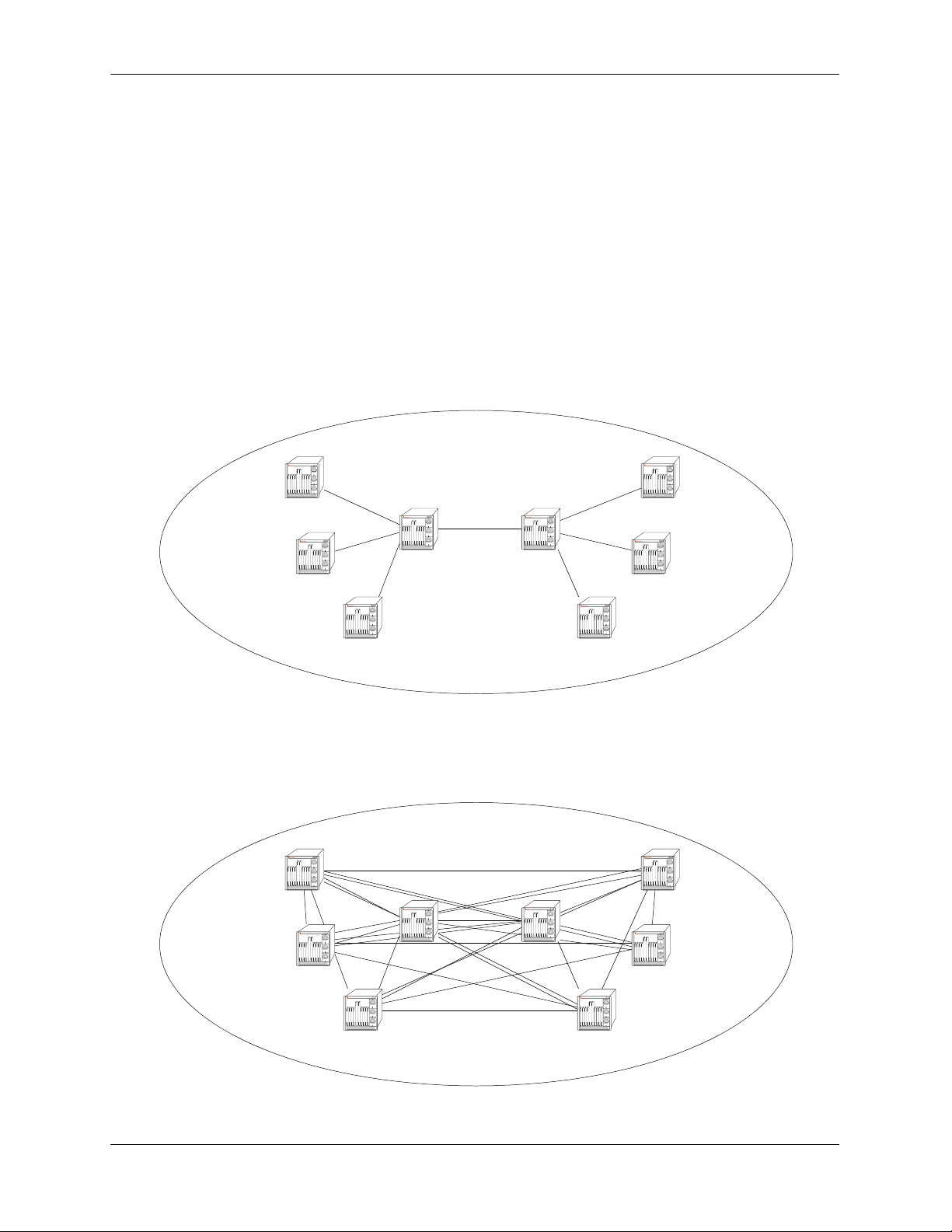
BGP Overview Configuring BGP
Route Reflectors
Route reflectors are useful if the internal BGP mesh becomes very large. A route reflector is a concentration router for other BGP peers in the local network, acting as a focal point for internal BGP sessions.
Multiple client BGP routers peer with the central route server (the reflector). The router reflectors then
peer with each other. Although BGP rules state that routes learned via one IBGP speaker cannot be advertised to another IBGP speaker, route reflection allows the router reflector servers to “reflect” routes,
thereby relaxing the IBGP standards.
Since the router clients in this scenario only peer with the router reflector, the session load per router is
significantly reduced. Route Reflectors are discussed further in “Setting Up Route Reflection” on
page 2-38.
The following picture demonstrates this concept:
AS 100 with Route Reflection
OmniSwitch 7700
TM
OmniSwitch 7700
TM
BGP Reflector 1 BGP Reflector 2
BGP Client 1
BGP Client 2
OmniSwitch 7700
TM
BGP Client 3
OmniSwitch 7700
TM
OmniSwitch 7700
TM
OmniSwitch 7700
TM
OmniSwitch 7700
TM
BGP Client 6
BGP Client 4
OmniSwitch 7700
TM
BGP Client 5
In the diagram above, Clients 1, 2, and 3 peer with Reflector 1, and Clients 4, 5, and 6 peer with Reflector
2. Reflector 1 and 2 peer with each other. This allows each BGP speaker to maintain only one BGP
session, rather than a possible seven sessions, as demonstrated below:
AS 100 without Route Reflection
OmniSwitch 7700
TM
OmniSwitch 7700
TM
OmniSwitch 7700
TM
OmniSwitch 7700
TM
OmniSwitch 7700
TM
OmniSwitch 7700
TM
OmniSwitch 7700
TM
OmniSwitch 7700
TM
page 2-8 OmniSwitch 7700/7800/8800 Advanced Routing Configuration Guide April 2006
Page 63

Configuring BGP BGP Overview
BGP Confederations
Confederations are another way of dealing with large networks with many BGP speakers. Like route
reflectors, confederations are recommended when speakers are forced to handle large numbers of BGP
sessions at the same time.
Confederations are sub ASs within a larger AS. Inside each sub AS, all the rules of IBGP apply. Since
each sub AS has its own AS number, EBGP must be used to communicate between sub ASs. The following example demonstrates a simple confederation set up:
EBGP
IBGP
OmniSwitch 7700
TM
AS 1001
OmniSwitch 7700
TM
OmniSwitch 7700
TM
OmniSwitch 7700
TM
OmniSwitch 7700
TM
OmniSwitch 7700
TM
AS 1002
AS 100
AS 100 is now a confederation consisting of AS 1001 and AS 1002. Even though EBGP is used to
communicate between AS 1001 and 1002, the entire confederation behaves as though it were using IBGP.
In other words, the sub AS attributes are preserved when crossing the sub AS boundaries.
Confederations are discussed further in “Creating a Confederation” on page 2-42.
OmniSwitch 7700/7800/8800 Advanced Routing Configuration Guide April 2006 page 2-9
Page 64

BGP Overview Configuring BGP
Policies
Routing policies enable route classification for importing and exporting routes. The goal of routing policies is to control traffic flow. Policies can be applied to egress and ingress traffic.
Policies act as filters to either permit or deny specified routes that are being learned or advertised from a
peer. The following diagram demonstrates this concept:
OmniSwitch 7700
TM
Incoming policy
(deny AS 300)
Route 1
OmniSwitch 7700
OmniSwitch 7700
TM
Route 1
TM
Route 2
AS 100
AS 200
OmniSwitch 7700
TM
AS 300
Routes from AS 200 and AS 300 are being learned by AS 100. However, there is an incoming AS Path
policy at the edge of AS 100 that prevents routes that originate in AS 300 from being propagated throughout AS 100.
There are four main policy types:
• AS Path. This policy filters routes based on AS path lists. An AS path list notes all of the ASs the route
travels to reach its destination.
• Community Lists. Community list policies filter routes based on the community to which a route
belongs. Communities can affect route behavior based on the definition of the community.
• Prefix Lists. Prefix list policies filter routes based on a specific network address, or a range of network
addresses.
• Route Maps. Route map policies filter routes by amalgamating other policies into one policy. It is a
way of combining many different filter options into one policy.
Creating and assigning policies is discussed in “Routing Policies” on page 2-43.
page 2-10 OmniSwitch 7700/7800/8800 Advanced Routing Configuration Guide April 2006
Page 65

Configuring BGP BGP Overview
Regular Expressions
Regular expressions are used to identify AS paths for purposes of making routing decisions. In this
context, an AS path is a list of one or more unsigned 16-bit AS numbers, in the range 1 through 65535.
An ordinary pattern match string looks like:
100 200
which matches any AS path containing the Autonomous System number 100 followed immediately by
200, anywhere within the AS path list. It would not match an AS path which was missing either number,
or where the numbers did not occur in the correct order, or where the numbers were not adjacent to one
another.
Special pattern matching characters (sometimes called metacharacters) add the ability to specify that part
of the pattern must match the beginning or end of the AS path list, or that some arbitrary number of AS
numbers should match, etc. The following table defines the metacharacters used in the BGP implementation.
Symbol Description
^ Matches the beginning of the AS path list.
123 Matches the AS number 123.
. Matches any single AS number.
? Matches zero or one occurrence of the previous token, which must be an AS number,
a dot, an alternation, or a range.
+ Matches one or more occurrences of the previous token, which must be an AS num-
ber, a dot, an alternation, or a range.
* Matches zero or more occurrences of the previous token, which must be an AS num-
ber, a dot, an alternation, or a range.
( Begins an alternation sequence of AS numbers. It matches any AS number listed in
the alternation sequence.
| Separates AS numbers in an alternation sequence.
) Ends an alternation sequence of AS numbers.
[ Begin a range pair consisting of two AS numbers separated by a dash. It matches any
AS number within that inclusive range.
- Separates the endpoints of a range.
] Ends a range pair.
$ Matches the end of the AS path list.
, _ Commas, underscores (_), and spaces are ignored.
The regular expressions configured in the router are compared against an incoming AS path list one at a
time until a match is found, or until all patterns have been unsuccessfully matched. Unlike some implementations, which use a character-based pattern matching logic, the BGP implementation treats AS
numbers as single tokens, providing two benefits:
OmniSwitch 7700/7800/8800 Advanced Routing Configuration Guide April 2006 page 2-11
Page 66

BGP Overview Configuring BGP
• It makes writing (and reading) policies much easier.
• It enables the router to begin using the policies more quickly after startup.
For example, to identify routes originating from internal autonomous systems, you would use the pattern:
[64512-65535]$
which means “match any AS number from 64512 to 65535 (inclusive) which occurs at the end of the AS
path.” To accomplish the same thing using character-based pattern matching, you would have to use the
following pattern:
(_6451[2-9]_|_645[2-9][0-9]_|_64[6-9][0-9][0-9]_|_65[0-9][0-9][0-9]_)$
Some examples of valid regular expressions are shown in the following table.
Example Description
100 Meaning: Any route which passes through AS number 100.
Matches: 100 200 300
300 100 100
Doesn’t Match: 200 300
^100 Meaning: Any routes for which the next hop is AS number 100.
Matches: 100 200 100
Doesn’t Match: 50 100 200
100$ Meaning: Any route which originated from AS number 100 (AS numbers are
prepended to the AS path list as they are passed on, so the originating AS is always the last number in the list).
Matches: 100
200 200 100
Doesn’t Match: 100 200
^100 500$ Meaning: A route with just two hops, 100 and 500.
Matches: 100 500
Doesn’t Match: 100 500 600
100 200 500
100 . . 200 Meaning: Any route with at least 4 hops, with 100 separated by any two hops
from 200.
Matches: 50 100 400 500 200 600
100 100 100 200
Doesn’t Match: 100 200
100 100 200
(100|200).+
[500-650]$
Meaning: Any route which begins with 100 or 200, ends with an AS number
between 500 and 650 (inclusive), and is at least three hops in length.
The “.+” part matches at least one (but possibly more) AS numbers.
page 2-12 OmniSwitch 7700/7800/8800 Advanced Routing Configuration Guide April 2006
Page 67

Configuring BGP BGP Overview
Matches: 100 350 501
200 250 260 270 280 600
Doesn’t Match: 100 600
100 400 600 700
^500 Meaning: Only routes consisting of a single AS, 500.
Matches: 500
Doesn’t Match: 500 600
100 500 600
[100-199]*
500
(900|950)$
Meaning: Any route which ends with any number of occurrences of AS num-
bers in the range 100 to 199, followed by 500, followed by either a
900 or 950.
Matches: 100 150 175 500 900
100 500 950
Doesn’t Match: 100 200 500 900
100 199 500
Some examples of invalid regular expressions are shown in the following table.
Error Description
66543 Number is too large. AS numbers must be in the range 1 to 65535.
64,512 Possibly an error, if the user meant the number 64512. The comma gets interpreted as
a separator, thus the pattern is equivalent to the two AS numbers 64 and 512
(100 200 | 300) Alternation sequences must consist of single AS numbers separated by vertical bars,
enclosed by parentheses.
(100*|200) No metacharacters other than vertical bars may be included within an alteration
sequence.
(100 |
Parthentheses may not be nested. This pattern is actually equivalent to (100|200|300).
(200|300))
100 ^ 200 The “^” metacharacter must occur first in the pattern, as it matches the beginning of
the AS path.
^500 $ 600 The “$” metacharacter must occur last in the pattern, as it matches the end of the AS
path.
^? 100 The repetition metacharacters (?,+,*) cannot be applied to the beginning of the line. If
it were legal, this pattern would be equivalent to the pattern: 100.
[1-(8|9)]* A range cannot contain an alternation sequence.
OmniSwitch 7700/7800/8800 Advanced Routing Configuration Guide April 2006 page 2-13
Page 68

BGP Overview Configuring BGP
The Route Selection Process
Several metrics are used to make BGP routing decisions. These metrics include the route’s local preference, the AS Path, and the Multi-Exit Discriminator (MED). These metrics are organized into a hierarchy
such that if a tie results, the next important criteria is used to break the tie until a decision is made for the
route path.
BGP selects the best path to an autonomous system from all known paths and propagates the selected path
to its neighbors. BGP uses the following criteria, in order, to select the best path. If routes are equal at a
given point in the selection process, then the next criterion is applied to break the tie.
1 The route with the highest local preference.
2 The route with the fewest autonomous systems listed in its AS Path.
3 The AS path origin. A route with an AS path origin of IGP (internal to the AS) is preferred. Next in
preference is a route with an AS path origin of EGP (external to the AS). Least preferred is an AS path that
is incomplete. In summary, the path origin preference is as follows: IGP < EGP < Incomplete.
4 The route with the lowest Multi-Exit Discriminator (MED). MEDs are by default compared between
routes that are received within the same AS. However, you can configure BGP to consider MED values
from external peers. This test is only applied if the local AS has two or more connections, or exits, to a
neighbor AS.
5 The route with a closer next hop (with respect to the internal routing distance).
6 The source of the route. A strictly interior route is preferred, next in preference is a strictly exterior
route, and third in preference is an exterior route learned from an interior session. In summary, the route
source preference is as follows: IGP < EBGP < IBGP.
7 Lowest BGP Router ID. The route whose next hop IP address is numerically lowest.
page 2-14 OmniSwitch 7700/7800/8800 Advanced Routing Configuration Guide April 2006
Page 69

Configuring BGP BGP Overview
Route Dampening
Route dampening is a mechanism for controlling route instability. If a route is enabled and disabled
frequently, it can cause an abundance of UPDATE and WITHDRAWN messages to expend speaker
resources. Route dampening categorizes a route as either behaved or ill behaved. A well behaved route
shows a high degree of stability over an extended period of time, while an ill behaved route shows a high
degree of instability over a short period of time. This instability is also known as flapping.
Route dampening can suppress (not advertise) an ill behaved route until it has achieved a certain degree of
stability. Route suppression is based on the number of times a route flaps over a period of time.
The following diagram illustrates this concept:
Route 1
Route 1
OmniSwitch 7700
TM
OmniSwitch 7700
TM
Route 2
(flapping)
Route 3
AS 100
Route 3
Routes 1, 2, and 3 are entering AS 100, but Route 2 (because it is flapping) has exceeded the dampening
threshold. It is therefore not propagated into the AS.
The dampening threshold and suppression time of a route is determined by various factors discussed in
“Controlling Route Flapping Through Route Dampening” on page 2-34.
CIDR Route Notation
Although CIDR is supported by the router, CIDR route notation is not supported on the CLI command
line. For example, in order to enter the route “198.16.10.0/24” you must input “198.16.10.0
255.255.255.0”. Some show commands, such as ip bgp policy prefix-list, do use CIDR notation to indicate route prefixes.
OmniSwitch 7700/7800/8800 Advanced Routing Configuration Guide April 2006 page 2-15
Page 70

BGP Configuration Overview Configuring BGP
BGP Configuration Overview
The following steps and points summarize configuring BGP. Not all of the following are necessary. For
the necessary steps to enable BGP on the OmniSwitch, see “Quick Steps for Using BGP” on page 2-3.
1 Load the BGP protocol. See “Starting BGP” on page 2-17.
2 Set up router-wide parameters, such as the router’s AS number, default local preference, and enable the
BGP protocol. See “Setting Global BGP Parameters” on page 2-18.
3 Configure peers on the router. These peers may be in the same AS as the router or in a different AS.
See “Configuring a BGP Peer” on page 2-24.
4 Configure peers that operate on remote routers. These peers may be in the same AS as the router or in a
different AS. See “Configuring a BGP Peer” on page 2-24.
5 Configure optional parameters. There are many optional features available in the Alcatel implementa-
tion of BGP-4. These features are described in later sections of this chapter. The following is a list of BGP
features you can configure on the OmniSwitch 7700/7800/8800:
• Aggregate Routes. See “Configuring Aggregate Routes” on page 2-30
• Local networks, or routes. See “Configuring Local Routes (Networks)” on page 2-31
• Route Dampening. See “Controlling Route Flapping Through Route Dampening” on page 2-34.
• Route Reflection. See “Setting Up Route Reflection” on page 2-38.
• Communities. See “Working with Communities” on page 2-41.
• Confederations. See “Creating a Confederation” on page 2-42.
• Route filtering based on AS path list, community affiliation, prefix list, or route map. “Configuring
Redistribution Filters” on page 2-51.
• Redistribution of routes from another protocol, such as RIP or OSPF. See “Configuring Redistribution
Filters” on page 2-51.
page 2-16 OmniSwitch 7700/7800/8800 Advanced Routing Configuration Guide April 2006
Page 71

Configuring BGP Starting BGP
Starting BGP
Before BGP is operational on your router you must load it to running memory and then administratively
enable the protocol using the ip load bgp and ip bgp status commands. Follow these steps to start BGP.
1 Install BGP image file in the active boot directory. The name of this file is fadvrout.img for the
OmniSwitch 7700/7800, and Eadvrout.img for the OmniSwitch 8800.
2 Load the BGP image into running memory by issuing the following command:
-> ip load bgp
3 Administratively enable BGP by issuing the following command
-> ip bgp status enable
Disabling BGP
You can administratively disable BGP by issuing the following command:
-> ip bgp status disable
Many BGP global commands require that you disable the protocol before changing parameters. The
following functions and commands require that you first disable BGP before issuing them:
Parameters Requiring that BGP first be disabled
Function Command
Router’s AS number ip bgp autonomous-system
Confederation Number ip bgp confederation identifier
Default local preference ip bgp default local-preference
IGP synchronization ip bgp synchronization
AS Path Comparison ip bgp bestpath as-path ignore
MED comparison ip bgp always-compare-med
Substitute missing MED value ip bgp bestpath med missing-as-
worst
Equal-cost multi-path comparison ip bgp maximum-paths
Route reflection ip bgp client-to-client reflection
Cluster ID in route reflector group ip bgp cluster-id
Fast External Fail Over ip bgp fast-external-failover
Enable logging of peer changes ip bgp log-neighbor-changes
Tag routes from OSPF ip bgp confederation identifier
OmniSwitch 7700/7800/8800 Advanced Routing Configuration Guide April 2006 page 2-17
Page 72

Setting Global BGP Parameters Configuring BGP
Setting Global BGP Parameters
Many BGP parameters are applied on a router-wide basis. These parameters are referred to as global BGP
parameters. These values are taken by BGP peers in the router unless explicitly overridden by a BGP peer
command. This section describes how to enable or disable BGP global parameters.
Global BGP Defaults
Parameter Description Command Default Value/Comments
Router’s AS number ip bgp autonomous-system 1
Confederation Number ip bgp confederation identifier No confederations configured
Default local preference ip bgp default local-preference 100
IGP synchronization ip bgp synchronization Disabled
AS Path Comparison ip bgp bestpath as-path ignore Enabled
MED comparison on external
peers
Substitute missing MED value ip bgp bestpath med missing-as-
Equal-cost multi-path support ip bgp maximum-paths Multiple paths supported
Route reflection ip bgp client-to-client reflection Disabled
Cluster ID in route reflector group ip bgp cluster-id 0.0.0.0
Fast External Fail Over ip bgp fast-external-failover Disabled
Enable logging of peer changes ip bgp log-neighbor-changes Disabled
Route dampening ip bgp dampening Disabled
ip bgp always-compare-med Disabled
Lowest (best) possible value
worst
page 2-18 OmniSwitch 7700/7800/8800 Advanced Routing Configuration Guide April 2006
Page 73

Configuring BGP Setting Global BGP Parameters
Setting the Router AS Number
The router takes a single Autonomous System (AS) number. You can assign one and only one AS number
to a router using the ip bgp autonomous-system command. That same router may contain peers that
belong to a different AS than the AS you assign your router. In such a case these BGP peers with a different AS would be considered external BGP (EBGP) peers and the communication with those peers would
be EBGP.
The following command would assign an AS number of 14 to a router:
-> ip bgp autonomous-system 14
This command requires that you first disable the BGP protocol. If BGP were already enabled, you would
actually need to issue two commands to assign the router’s AS number to 14:
-> ip bgp status disable
-> ip bgp autonomous-system 14
Setting the Default Local Preference
A route’s local preference is an important attribute in the path selection process. In many cases it will be
the most important criteria in determining the selection of one route over another. A route obtains its local
preference in one of two ways:
• By taking the default local preference established globally in the router
• By having this default local preference manipulated by another command. The BGP peer, aggregate
route, and network commands allow you to assign a local preference to a route. It is also possible to
manipulate the local preference of a route through BGP policy commands.
The local preference in the router is set by default to 100. If you want to change this value, use the ip bgp
default local-preference command. For example, if you wanted to change the default local preference for
all routes to 200, you would issue the following command:
-> ip bgp default local-preference 200
This command requires that you first disable the BGP protocol. If BGP were already enabled, you would
actually need to issue two commands to change the default local preference to 200:
-> ip bgp status disable
-> ip bgp default local-preference 200
OmniSwitch 7700/7800/8800 Advanced Routing Configuration Guide April 2006 page 2-19
Page 74

Setting Global BGP Parameters Configuring BGP
Enabling AS Path Comparison
The AS path is a route attribute that shows the sequence of ASs through which a route has traveled. For
example if a path originated in AS 1, then went through AS 3, and reached its destination in AS4, then the
AS path would be
4 3 1
A shorter AS path is preferred over a longer AS path. The AS path is always advertised in BGP route
updates, however you can control whether BGP uses this attribute when comparing routes. The length of
the AS path may not always indicate the effectiveness for a given route. For example, if a route has an AS
path of:
1 3 4
using only T1 links, it might not be a faster path than a longer AS path of:
2 4 5 7
that uses only DS-3 links.
By default AS path comparison is enabled. You can disable it by specifying:
-> no ip bgp bestpath as-path ignore
This command requires that you first disable the BGP protocol. If BGP were already enabled, you would
actually need to issue two commands to turn off AS path comparison:
-> ip bgp status disable
-> no ip bgp bestpath as-path ignore
page 2-20 OmniSwitch 7700/7800/8800 Advanced Routing Configuration Guide April 2006
Page 75

Configuring BGP Setting Global BGP Parameters
Controlling the use of MED Values
The Multi Exit Discriminator, or MED, is used by border routers (i.e., BGP speakers with links to neighboring autonomous systems) to help choose between multiple entry and exit points for an autonomous
system. It is only relevant when an AS has more than one connection to a neighboring AS. If all other
factors are equal, the path with the lowest MED value takes preference over other paths to the neighbor
AS.
If received on external links, the MED may be propagated over internal links to other BGP speakers in the
same AS. However, the MED is never propagated to speakers in a neighboring AS. The MED attribute
indicates the weight of a particular exit point from an AS. Some exit points may be given a better MED
value because they lead to higher speed connections.
The Alcatel implementation of BGP allows you to control MED values in the following ways:
• Compare MED values for external ASs
• Insert a MED value in routes that do not contain MEDs
The following two sections describe these MED control features.
Enabling MED Comparison for External Peers
By default, BGP only compares MEDs from peers within the same autonomous system when selecting
routes. However, you can configure BGP to compare MEDs values received from external peers, or other
autonomous systems. To enable MED comparison of external peers specify:
-> ip bgp always-compare-med
This command requires that you first disable the BGP protocol. If BGP were already enabled, you would
actually need to issue two commands to disable MED comparison:
-> ip bgp status disable
-> no ip bgp always-compare-med
Inserting Missing MED Values
A MED value may be missing in a route received from an external peer. Your can specify how a missing
MED in an external BGP path is to be treated for route selection purposes. The default behavior is to treat
missing MEDs as zero (best). The ip bgp bestpath med missing-as-worst command allows you to treat
missing MEDs as 2
32-1
(worst) for compatibility reasons.
To change the missing MED value from worst to best, enter the following command:
-> ip bgp bestpath med missing-as-worst
OmniSwitch 7700/7800/8800 Advanced Routing Configuration Guide April 2006 page 2-21
Page 76

Setting Global BGP Parameters Configuring BGP
Synchronizing BGP and IGP Routes
The default behavior of BGP requires that it must be synchronized with the IGP before BGP may advertise transit routes to external ASs. It is important that your network is consistent about the routes it advertises, otherwise traffic can be lost.
The BGP rule is that a BGP router should not advertise to external neighbors destinations learned from
IBGP neighbors unless those destinations are also known via an IGP. This is known as synchronization. If
a router knows about a destination via an IGP, it is assumed that the route has already been propagated
inside the AS and internal reachability is ensured.
The consequence of injecting BGP routes inside an IGP is costly. Redistributing routes from BGP into the
IGP results in major overhead on the internal routers, and IGPs are really not designed to handle that many
routes.
The ip bgp synchronization command enables or disables BGP internal synchronization. Enabling this
command will force all routers (BGP and non-BGP) in an AS to learn all routes learned over external
BGP. Learning the external routes forces the routing tables for all routers in an AS to be synchronized and
ensure that all routes advertised within an AS are known to all routers (BGP and non-BGP). However,
since routes learned over external BGP can be numerous, enabling synchronization can place an extra
burden on non-BGP routers.
To enable synchronization, enter the following command:
-> ip bgp synchronization
The BGP speaker will now synchronize with the IGP. The default for synchronization is disabled.
To deactivate synchronization, enter the same command with the no keyword, as shown:
-> no ip bgp synchronization
page 2-22 OmniSwitch 7700/7800/8800 Advanced Routing Configuration Guide April 2006
Page 77

Configuring BGP Setting Global BGP Parameters
Displaying Global BGP Parameters
The following list shows the commands for viewing the various aspects of BGP set with the global BGP
commands:
show ip bgp Displays the current global settings for the local BGP speaker.
show ip bgp statistics Displays BGP global statistics, such as the route paths.
show ip bgp aggregate-address Displays aggregate configuration information.
show ip bgp dampening Displays the current route dampening configuration settings.
show ip bgp dampening-stats Displays route flapping statistics.
show ip bgp network Displays information on the currently defined BGP networks.
show ip bgp path Displays information, such as Next Hop and other BGP attributes, for
every path in the BGP routing table.
show ip bgp routes Displays information on BGP routes known to the router. This informa-
tion includes whether changes to the route are in progress, whether it is
part of an aggregate route, and whether it is dampened.
For more information about the output from these show commands, see the OmniSwitch CLI Reference
Guide.
OmniSwitch 7700/7800/8800 Advanced Routing Configuration Guide April 2006 page 2-23
Page 78

Configuring a BGP Peer Configuring BGP
Configuring a BGP Peer
BGP supports two types of peers, or neighbors: internal and external. Internal sessions are run between
BGP speakers in the same autonomous system (AS). External sessions are run between BGP peers in
different autonomous systems. Internal neighbors may be located anywhere within the same autonomous
system while external neighbors are adjacent to each other and share a subnet. Internal neighbors usually
share a subnet.
BGP speakers can be organized into groups that share similar parameters, such as metrics, timers, and
route preferences. It is also possible to configure individual speakers with unique parameters.
An OmniSwitch is assigned an AS number. That same router may contain peers with different AS
numbers. The router may also contain information on peer routers residing in different physical routers.
However, the OmniSwitch will not dynamically learn about peers in other routers; you must explicitly
configure peers operating in other routers.
Note. In the following document, the BGP terms “peer” and “neighbor” are used interchangeably to mean
any BGP entity known to the local router.
Peer Command Defaults
The following table lists the default values for many of the peer commands:
Parameter Description Command
Configures the time interval for
updates between external BGP
peers.
Enables or disables BGP peer
automatic restart.
Configures this peer as a client to
the local route reflector.
The interval, in seconds,
between
BGP retries to set up a
ip bgp neighbor advertisement-interval 30
ip bgp neighbor auto-restart enabled
ip bgp neighbor route-reflector-client disabled
ip bgp neighbor conn-retry-interval 120
connection via the transport
protocol with another peer.
Enables or disables BGP peer
default origination.
Configures the tolerated hold
time interval, in seconds, for
messages to this peer from other
peers.
ip bgp neighbor default-originate disabled
ip bgp neighbor timers 180
Default Value/
Comments
Configures the time interval
between KEEPALIVE messages
sent by this peer.
page 2-24 OmniSwitch 7700/7800/8800 Advanced Routing Configuration Guide April 2006
ip bgp neighbor timers 60
Page 79

Configuring BGP Configuring a BGP Peer
Parameter Description Command
Configures the maximum number
of prefixes, or paths, the local
ip bgp neighbor maximum-prefix
warning-only
Default Value/
Comments
5000
router can receive from this peer
in UPDATE messages.
Allows external peers to commu-
ip bgp neighbor ebgp-multihop disabled
nicate with each other even when
they are not directly connected.
Configures the BGP peer name. ip bgp neighbor description peer IP address
Sets the BGP peer to use next hop
ip bgp neighbor next-hop-self disabled
processing behavior
Configures the local BGP
ip bgp neighbor passive disabled
speaker to wait for this peer to
establish a connection.
Enables or disables the stripping
ip bgp neighbor remove-private-as disabled
of private autonomous system
numbers from the AS path of
routes destined to this peer.
Enables or disables BGP peer
ip bgp neighbor soft-reconfiguration enabled
soft reconfiguration.
Configures this peer as a member
ip bgp confederation neighbor disabled
of the same confederation as the
local BGP speaker.
Enable or disables maximum pre-
ip bgp neighbor update-source 80 percent
fix warning for a peer.
Configures the local address from
ip bgp neighbor update-source defaults to Router ID
which this peer will be contacted.
Note. BGP peers that do not reside in the router are not dynamically learned. For this reason, peers that are
external to the router must be manually configured using peer commands. The local BGP speaker will
advertise routes to BGP peers in other routers as long as those peers are configured locally with the ip bgp
neighbor command.
OmniSwitch 7700/7800/8800 Advanced Routing Configuration Guide April 2006 page 2-25
Page 80

Configuring a BGP Peer Configuring BGP
Creating a Peer
1 Create the peer and assign it an address using the ip bgp neighbor command. For example to create a
peer with an address of 190.17.20.16 you would enter:
-> ip bgp neighbor 190.17.20.16
2 Assign an AS number to the peer using the ip bgp neighbor remote-as command. For example to
assign the peer created in Step 1 to AS number 100, you would enter:
-> ip bgp neighbor 190.17.20.16 remote-as 100
The AS number for a peer defaults to 1 if you do not configure an AS number through the
ip bgp neighbor remote-as command.
3 You can optionally assign this peer a descriptive name using the ip bgp neighbor description
command. Such a name may be helpful particularly in networks with connections to more than one ISP.
For example, you could name peers based on their connection to a given ISP. In the example above, you
could name the peer “FastISP” as follows:
-> ip bgp neighbor 190.17.20.16 description FastISP
4 Configure optional attributes for the peer. You can configure many attributes for a peer; these attributes
are listed in the table below along with the commands used to configure them.
Optional BGP Peer Parameters
Peer Parameter Command
Interval between route advertisements
ip bgp neighbor advertisement-interval
with external peers.
Enables or disables BGP peer automatic
ip bgp neighbor auto-restart
restart.
The interval, in seconds, between BGP
ip bgp neighbor conn-retry-interval
retries to set up a connection via the
transport protocol with another peer.
Enables or disables BGP peer default
ip bgp neighbor default-originate
origination.
Configures the tolerated hold time inter-
ip bgp neighbor timers
val, in seconds, for messages to this peer
from other peers.
Configures the time interval between
ip bgp neighbor timers
KEEPALIVE messages sent by this peer.
Configures the maximum number of prefixes, or paths, the local router can
ip bgp neighbor maximum-prefix
warning-only
receive from this peer in UPDATE messages.
Enable or disables maximum prefix
ip bgp neighbor update-source
warning for a peer.
Allows external peers to communicate
ip bgp neighbor ebgp-multihop
with each other even when they are not
directly connected.
page 2-26 OmniSwitch 7700/7800/8800 Advanced Routing Configuration Guide April 2006
Page 81

Configuring BGP Configuring a BGP Peer
Peer Parameter Command
Sets the BGP peer to use next hop pro-
ip bgp neighbor next-hop-self
cessing behavior.
Configures the local BGP speaker to wait
ip bgp neighbor passive
for this peer to establish a connection.
Enables or disables the stripping of pri-
ip bgp neighbor remove-private-as
vate autonomous system numbers from
the AS path of routes destined to this
peer.
Enables or disables BGP peer soft recon-
ip bgp neighbor soft-reconfiguration
figuration.
5 After entering all commands to configure a peer you need to administratively enable the peer. The peer
will not begin advertising routes until you enable it. To enable the peer in the above step, enter the ip bgp
neighbor status command:
-> ip bgp neighbor 190.17.20.16 status enable
Restarting a Peer
Many BGP peer commands will automatically restart the peer once they are executed. By restarting the
peer, these parameters take effect as soon as the peer comes back up. However, there are some peer
commands (such as those configuring timer values) that do not reset the peer. If you want these parameters to take effect, then you must manually restart the BGP peer using the ip bgp neighbor clear. The
following command would restart the peer at address 190.17.20.16:
-> ip bgp neighbor 190.17.20.16 clear
The peer is not available to send or receive update or notification messages while it is restarting.
Use the ip bgp neighbor clear soft command to reset peer policy parameters.
Setting the Peer Auto Restart
When the auto restart is enabled, this peer will automatically attempt to restart a session with another peer
after a session with that peer terminates.
To enable the auto restart feature, enter the ip bgp neighbor auto-restart command with the peer IP
address, as shown:
-> ip bgp neighbor 190.17.20.16 auto-restart
To disable this feature, enter the following:
-> no ip bgp neighbor 190.17.20.16 auto-restart
OmniSwitch 7700/7800/8800 Advanced Routing Configuration Guide April 2006 page 2-27
Page 82

Configuring a BGP Peer Configuring BGP
Changing a Peer Address to the Local Router Address
A peer’s local address is used to contact a peer. It is possible to change the local address learned from a
specific peer.
The configured local address does not override the router identification for this BGP peer (configured in
the ip bgp neighbor command). It is the address through which this peer can be contacted within this
router. The router identification for a peer, especially an external peer, may not exist in the local router,
but that distant peer can still be contacted via this router. This command sets the local address through
which this distant peer can be contacted.
For example, to configure a peer with an IP address of 120.5.4.6 to be contacted via 120.5.4.10, enter the
ip bgp neighbor update-source command as shown:
-> ip bgp neighbor 120.5.4.6 update-source 12.5.4.10
Alternatively, you can enter the name of the local IP interface, instead of the IP address as shown below:
-> ip bgp neighbor 120.5.4.6 update-source vlan-23
Clearing Statistics for a Peer
BGP tracks the number of messages sent to and received from other peers. It also breaks down messages
into UPDATE, NOTIFICATION, and TRANSITION categories. You can reset, or clear, the statistics for a
peer using the ip bgp peer stats-clear command. For example the following use of the ip bgp neighbor
stats-clear command would clear statistics for the peer at address 190.17.20.16:
-> ip bgp neighbor 190.17.20.16 stats-clear
The statistics that are cleared are shown in the show ip bgp neighbors statistics command. The following
is an example of output from this command:
-> show ip bgp neighbors statistics 190.17.20.16
Neighbor address = 190.17.20.16,
# of UP transitions = 0,
Time of last UP transition = 00h:00m:00s,
# of DOWN transitions = 0,
Time of last DOWN transition = 00h:00m:00s,
Last DOWN reason = none,
# of msgs rcvd = 0,
# of Update msgs rcvd = 0,
# of prefixes rcvd = 0,
# of Route Refresh msgs rcvd = 0,
# of Notification msgs rcvd = 0,
Last rcvd Notification reason = none [none]
Time last msg was rcvd = 00h:00m:00s,
# of msgs sent = 0,
# of Update msgs sent = 0,
# of Route Refresh msgs sent = 0
# of Notification msgs sent = 0,
Last sent Notification reason = none [none]
Time last msg was sent = 00h:00m:00s,
page 2-28 OmniSwitch 7700/7800/8800 Advanced Routing Configuration Guide April 2006
Page 83

Configuring BGP Configuring a BGP Peer
Setting Peer Authentication
You can set which MD5 authentication key this router will use when contacting a peer. To set the MD5
authentication key, enter the peer IP address and key with the ip bgp neighbor md5 key command:
-> ip bgp neighbor 123.24.5.6 md5 key keyname
The peer with IP address 123.24.5.6 will be sent messages using “keyname” as the encryption password. If
this is not the password set on peer 123.24.5.6, then the local router will not be able to communicate with
this peer.
Setting the Peer Route Advertisement Interval
The route advertisement interval specifies the frequency at which routes external to the autonomous
system are advertised. These advertisements are also referred to as UPDATE messages. This interval
applies to advertisements to external peers.
To set the advertisement interval, enter the number of seconds in conjunction with the
ip bgp neighbor advertisement-interval command, as shown:
-> ip bgp neighbor advertisement-interval 50
The interval is now set to 50 seconds. The default value is 30.
Configuring a BGP Peer with the Loopback0 Interface
Loopback0 is the name assigned to an IP interface to identify a consistent address for network management purposes. The Loopback0 interface is not bound to any VLAN, so it will always remain operationally active. This differs from other IP interfaces in that if there are no active ports in the VLAN, all IP
interface associated with that VLAN are not active. In addition, the Loopback0 interface provides a unique
IP address for the switch that is easily identifiable to network management applications.
It is possible to create BGP peers using the Loopback0 IP interface address of the peering router and binding the source (i.e., outgoing IP interface for the TCP connection) to its own configured Loopback0 interface. The Loopback0 IP interface address can be used for both Internal and External BGP peer sessions.
For EBGP sessions, if the External peer router is multiple hops away, the ebgp-multihop parameter may
need to be used.
The following example command configures a BGP peering session using a Loopback0 IP interface
address:
-> ip bgp neighbor 2.2.2.2 update-source Loopback0
See the OmniSwitch 7700/7800/8800 Network Configuration Guide for more information about configuring an IP Loopback0 interface.
OmniSwitch 7700/7800/8800 Advanced Routing Configuration Guide April 2006 page 2-29
Page 84

Configuring Aggregate Routes Configuring BGP
Configuring Aggregate Routes
Aggregate routes are used to reduce the size of routing tables by combining the attributes of several different routes and allowing a single aggregate route to be advertised to peers.
You cannot aggregate an address (for example, 100.10.0.0) if you do not have at least one more-specific
route of the address (for example, 100.10.20.0) in the BGP routing table.
Aggregate routes do not need to be known to the local BGP speaker.
1 Indicate the address and mask for the aggregate route using the ip bgp aggregate-address command:
-> ip bgp aggregate-address 172.22.2.0 255.255.255.0
2 Optional. When an aggregate route is created BGP does not aggregate the AS paths of all routes
included in the aggregate. However, you may specify that a new AS path be created for the aggregate
route that includes the ASs traversed for all routes in the aggregate. To specify that the AS path also be
aggregated use the ip bgp aggregate-address as-set command. For example:
-> ip bgp aggregate-address 172.22.2.0 255.255.255.0 as-set
3 Optional. By default an aggregate route suppresses the advertisement of all more-specific routes within
the aggregate. This suppression of routes is the function of an aggregate route. However, you can disable
route summarization through the no ip bgp aggregate-address summary-only. For example:
no ip bgp aggregate-address 172.22.2.0 255.255.255.0 summary-only
4 Optional. You can manipulate several BGP attributes for routes included in this aggregate route. These
attributes and the corresponding commands used to manipulate them are shown in the table below.
Optional Aggregate Route Attribute Manipulation
BGP Attribute Command
Community list for this aggregate route ip bgp aggregate-address community
Local preference value for this aggregate.
ip bgp aggregate-address local-preference
This value overrides the value set in the
ip bgp default-lpref command.
MED value for this aggregate route. ip bgp aggregate-address metric
5 Once you have finished configuring values for this aggregate route, enable it using the
ip bgp aggregate-address status command. For example:
->ip bgp aggregate-address 172.22.2.0 255.255.255.0 status enable
page 2-30 OmniSwitch 7700/7800/8800 Advanced Routing Configuration Guide April 2006
Page 85

Configuring BGP Configuring Local Routes (Networks)
Configuring Local Routes (Networks)
A local BGP network is used to indicate to BGP that a network should originate from a specified router. A
network must be known to the local BGP speaker; it also must originate from the local BGP speaker.
Networks have some parameters that can be configured (local-preference, community, metric). Note that
the network specified must be known to the router, whether it is connected, static, or dynamically learned.
This is not the case for an aggregate.
Adding the Network
To add a local network to a BGP speaker, use the IP address and mask of the local network in conjunction
with the ip bgp network command, as shown:
-> ip bgp network 172.20.2.0 255.255.255.0
In this example, network 172.20.2.0 with a mask of 255.255.255.0 is the local network for this BGP
speaker.
To remove the same network from the speaker, enter the same command with the no keyword, as shown:
-> no ip bgp network 172.20.2.0 255.255.255.0
The network would now no longer be associated as the local network for this BGP speaker.
Enabling the Network
Once the network has been added to the speaker, it must be enabled on the speaker. To do this, enter the IP
address and mask of the local network in conjunction with the ip bgp network status command, as
shown:
-> ip bgp network 172.20.2.0 255.255.255.0 status enable
In this example, network 172.20.2.0 with a mask of 255.255.255.0 has now been enabled.
To disable the same network, enter the following:
-> ip bgp network 172.20.2.0 255.255.255.0 status disable
The network would now be disabled, though not removed from the speaker.
OmniSwitch 7700/7800/8800 Advanced Routing Configuration Guide April 2006 page 2-31
Page 86

Configuring Local Routes (Networks) Configuring BGP
Configuring Network Parameters
Once a local network is added to a speaker, you can configure three parameters that are attached to routes
generated by the ip bgp network command. These three attributes are the local preference, the community, and the route metric.
Local Preference
The local preference is a degree of preference to be given to a specific route when there are multiple routes
to the same destination. The higher the number, the higher the preference. For example, a route with a
local preference of 50 will be used before a route with a local preference of 30.
To set the local preference for the local network, enter the IP address and mask of the local network in
conjunction with the ip bgp network local-preference command and value, as shown:
-> ip bgp network 172.20.2.0 255.255.255.0 local-preference 600
The local preference for routes generated by the network is now 600. The default value is 0 (no network
local preference is set).
Community
Communities are a way of grouping BGP peers that do not share an IP subnet or an AS. Adding the local
network to a specified community means the network will adopt the attributes of the community.
To add a network to a community, enter the local network IP address and mask in conjunction with the ip
bgp network community command and name, as shown:
-> ip bgp network 172.20.2.0 255.255.255.0 community 100:200
Network 172.20.2.0, mask 255.255.255.0, is now in the 100:200 community. The default community is no
community.
To remove the local network from the community, enter the local network as above with the community
set to “none”, as shown:
-> ip bgp network 172.20.2.0 255.255.255.0 community none
The network is now no longer in any community.
Metric
A metric for a network is the Multi-Exit Discriminator (MED) value. This value is used when announcing
this network to internal peers; it indicates the best exit point from the AS, assuming there is more than one.
A lower value indicates a more preferred exit point. For example, a route with a MED of 10 is more likely
to be used than a route with an MED of 100.
To set the network metric value, enter the network IP address and mask in conjunction with the ip bgp
network metric command and value, as shown:
-> ip bgp network 172.20.2.0 255.255.255.0 metric 100
Network 172.20.2.0, mask 255.255.255.0, is now set with a metric of 100. The default metric is 0.
page 2-32 OmniSwitch 7700/7800/8800 Advanced Routing Configuration Guide April 2006
Page 87

Configuring BGP Configuring Local Routes (Networks)
Viewing Network Settings
To view the network settings for all networks assigned to the speaker, enter the show ip bgp network
command, as shown:
-> show ip bgp network
A display similar to the following appears:
Network Mask Admin state Oper state
---------------+---------------+-----------+----------
155.132.40.0 255.255.255.0 disabled not_active
155.132.1.3 255.255.255.255 disabled not_active
To display a specific network, enter the same command with the network IP address and mask, as shown:
-> show ip bgp network 172.20.2.0 255.255.255.0
A display similar to the following appears:
Network address = 172.20.2.0,
Network mask = 255.255.255.0,
Network admin state = disabled,
Network oper state = not_active,
Network metric = 0,
Network local pref = 0,
Network community string = 0:500 400:1 300:2
OmniSwitch 7700/7800/8800 Advanced Routing Configuration Guide April 2006 page 2-33
Page 88

Controlling Route Flapping Through Route Dampening Configuring BGP
Controlling Route Flapping Through Route Dampening
Route dampening minimizes the effect of flapping routes in a BGP network. Route flapping occurs when
route information is updated erratically, such as when a route is announced and withdrawn at a rapid rate.
Route flapping can cause problems in networks connected to the Internet, where route flapping will
involve the propagation of many routes. Route dampening suppresses flapping routes and designates them
as unreachable until they flap at a lower rate.
You can configure route dampening to adapt to the frequency and duration of a particular route that is
flapping. The more a route flaps during a period of time, the longer it will be suppressed.
Each time a route flaps (i.e., withdrawn from the routing table), its “instability metric” is increased by 1.
Once a route’s instability metric reaches the suppress value, it is suppressed and no longer advertised. The
instability metric may continue to increase even after the route is suppressed.
A route’s instability metric may be reduced. It is reduced once the route stops flapping for a given period
of time. This period of time is referred to as the half-life duration. If a suppressed route does not flap for a
given half-life duration, then its instability metric will be cut in half. As long as the route continues to be
stable, its instability metric will be reduced until it reaches the reuse value. Once below the reuse value, a
route will be re-advertised.
Example: Flapping Route Suppressed, then Unsuppressed
Consider, for example, a route that has started to flap. Once this route starts exhibiting erratic behavior,
BGP begins tracking the instability metric for the route. This particular route flaps more than 300 times,
surpassing the cutoff value of 300. BGP stops advertising the route; the route is now suppressed. The route
continues to flap and its instability metric reaches 1600.
Now the route stops flapping. In fact, it does not flap for 5 minutes, which is also the half-life duration
defined for BGP routes. The instability metric is reduced to 800. The route remains stable for another 5
minutes and the instability metric is reduced to 400. After another 5 minutes of stability, the route’s instability metric is reduced to 200, which is also the defined re-use value. Since the instability metric for the
route has dropped below the reuse value, BGP will begin re-advertising it again.
The following chart illustrates what happens to the described route in the above scenario:
1600
Half-life duration exceeded.
Instability metric halved.
Instability
metric
800
600
400
200
Instability metric cut in
half two more times.
Route Suppressed
Instability metric hits reuse
value. Route unsuppressed.
510152025
Time
page 2-34 OmniSwitch 7700/7800/8800 Advanced Routing Configuration Guide April 2006
Page 89

Configuring BGP Controlling Route Flapping Through Route Dampening
Enabling Route Dampening
Route dampening is disabled by default. Route dampening must be enabled before it effects routes. To
enable route dampening on a BGP router, enter the ip bgp dampening command, as shown:
-> ip bgp dampening
To disable route dampening, enter the following:
-> no ip bgp dampening
Configuring Dampening Parameters
There are several factors in configuring route dampening. These factors work together to determine if a
route should be dampened, and for how long. The values all have defaults that are in place when dampening is enabled. It is possible to change these values, using the ip bgp dampening command with variables. The variables for these parameters must be entered together, in one command, in order. This is
demonstrated in the following sections.
• Setting the Reach Halflife. The reach halflife is the number of seconds a route can be reached, without
flapping, before the penalty number (of flaps) is reduced by half. See “Setting the Reach Halflife” on
page 2-35 for instructions on how this is done.
• Setting the Reuse Value. The reuse value determines if a route is advertised again. See “Setting the
Reuse Value” on page 2-36 for instructions on how this is done.
• Setting the Suppress Value. The suppress value is the number of route withdrawals required before the
route is suppressed. See “Setting the Suppress Value” on page 2-36 for instructions on how this is
done.
• Setting the Maximum Suppress Holdtime. The maximum holdtime is the number of seconds a route
stays suppressed. See “Setting the Maximum Suppress Holdtime” on page 2-36 for instructions on how
this is done.
Setting the Reach Halflife
The reach halflife value is the number of seconds that pass before a route is re-evaluated in terms of flapping. After the number of seconds set for halflife has passed, and a route has not flapped, then its total flap
count is reduced by half.
For example, if the reach halflife is set at 500 seconds, and a reachable route with a flap count of 300 does
not flap during this time, then its flap count is reduced to 150.
To change one variable to a number different than its default value, you must enter all of the variables
with the ip bgp dampening command in the correct order.
For example, to set the reach halflife value to 500, enter the halflife value and other variables with the
following command, as shown:
-> ip bgp dampening half-life 500 reuse 200 suppress 300 max-suppress-time 1800
In this example, the other variables have been set to their default values. The reach halflife is now set to
500. The default values for the reach halflife is 300.
OmniSwitch 7700/7800/8800 Advanced Routing Configuration Guide April 2006 page 2-35
Page 90

Controlling Route Flapping Through Route Dampening Configuring BGP
Setting the Reuse Value
The dampening reuse value is used to determine if a route should be re-advertised. If the number of flaps
for a route falls below this number, then the route is re-advertised. For example, if the reuse value is set at
150, and a route with 250 flaps exceeds the reach halflife it would be re-advertised as its flap number
would now be 125.
To change one variable to a number different than its default value, you must enter all of the variables with
the ip bgp dampening command in the correct order.
For example, to set the reuse value to 500, enter the reuse value and other variables with the following
command, as shown:
-> ip bgp dampening half-life 300 reuse 500 suppress 300 max-suppress-time 1800
In this example, the other variables have been set to their default values. The reuse value is now set to 500.
The default value is 200.
Setting the Suppress Value
The dampening suppress value sets the number of times a route can flap before it is suppressed. A
suppressed route is not advertised. For example, if the cutoff value is set at 200, and a route flaps 201
times, it will be suppressed.
To change one variable to a number different than its default value, you must enter all of the variables with
the ip bgp dampening command in the correct order.
For example, to set the suppress value to 500, enter the suppress value and other variables with the following command, as shown:
-> ip bgp dampening half-life 300 reuse 200 suppress 500 max-suppress-time 1800
In this example, the other variables have been set to their default values. The suppress value is now set to
500. The default value is 300.
Setting the Maximum Suppress Holdtime
The maximum suppress holdtime is the number of seconds a route stays suppressed once it has crossed the
dampening cutoff flapping number. For example, if the maximum holdtime is set to 500, once a route is
suppressed the local BGP speaker would wait 500 seconds before advertising the route again.
To change one variable to a number different than its default value, you must enter all of the variables with
the ip bgp dampening command in the correct order.
For example, to set the maximum suppress holdtime value to 500, enter the maximum suppress holdtime
value and other variables with the following command, as shown:
-> ip bgp dampening half-life 300 reuse 200 suppress 300 max-suppress-time 500
In this example, the other variables have been set to their default values. The maximum suppress holdtime
is now set to 500 seconds. The default value is 1800 seconds.
page 2-36 OmniSwitch 7700/7800/8800 Advanced Routing Configuration Guide April 2006
Page 91

Configuring BGP Controlling Route Flapping Through Route Dampening
Clearing the History
By clearing the dampening history, you are resetting all of the dampening information on all of the routes
back to zero, as if dampening had just been activated. Route flap counters are reset and any routes that
were suppressed due to route flapping violations are unsuppressed. Dampening information on the route
will start re-accumulating as soon as the command is entered and the statistics are cleared.
To clear the dampening history, enter the following command:
-> ip bgp dampening clear
Displaying Dampening Settings and Statistics
To display the current settings for route dampening, enter the following command:
-> show ip bgp dampening
A display similar to the following will appear:
Admin Status = disabled,
Half life value (seconds) = 300,
Reuse value (seconds) = 200
Suppress time (seconds) = 300,
Max suppress time (seconds) = 1800,
To display current route dampening statistics, enter the following command:
-> show ip bgp dampening-stats
A display similar to the following will appear:
Network Mask From Flaps Duration FOM
---------------+---------------+---------------+-----+-----------+-----
155.132.44.73 255.255.255.255 192.40.4.121 8 00h:00m:35s 175
OmniSwitch 7700/7800/8800 Advanced Routing Configuration Guide April 2006 page 2-37
Page 92

Setting Up Route Reflection Configuring BGP
Setting Up Route Reflection
BGP requires that all speakers in an autonomous system be fully meshed (i.e., each speaker must have a
peer connection to every other speaker in the AS) so that external routing information can be distributed to
all BGP speakers in an AS. However, fully meshed configurations are difficult to scale in large networks.
For this reason, BGP supports route reflection, a configuration in which one or more speakers—route
reflectors—handle intra-AS communication among all BGP speakers.
In a fully meshed BGP configuration, a BGP speaker that receives an external route must re-advertise the
route to all internal peers. In the illustration below, BGP speaker A receives a route from an external BGP
speaker and advertises it to both Speakers B and C in its autonomous system. Speakers B and C do not readvertise the route to each other so as to prevent a routing information loop.
AS 100
Speaker C
OmniSwitch 7700
TM
Route
External BGP
OmniSwitch 7700
TM
Speaker A
OmniSwitch 7700
TM
Speaker
Speaker B
Fully Meshed BGP Peers
In the above example, Speakers B and C do not re-advertise the external route they each received from
Speaker A. However, this fundamental routing rule is relaxed for BGP speakers that are route reflectors.
page 2-38 OmniSwitch 7700/7800/8800 Advanced Routing Configuration Guide April 2006
Page 93

Configuring BGP Setting Up Route Reflection
This same configuration using a route reflector would not require that all BGP speakers be fully meshed.
One of the speakers is configured to be a route reflector for the group. In this case, the route reflector is
Speaker C. When the route reflector (Speaker C) receives route information from Speaker A it advertises
the information to Speaker B. This set up eliminates the peer connection between Speakers A and B:
AS 100
Route Reflector
OmniSwitch 7700
TM
Route
External BGP
OmniSwitch 7700
TM
Client A
OmniSwitch 7700
TM
Speaker
Client B
The internal peers of a route reflector are divided into two groups: client peers and non-client peers. The
route reflector sits between these two groups and reflects routes between them. The route reflector, its
clients, and non-clients are all in the same autonomous system.
The route reflector and its clients form a cluster. The client peers do not need to be fully meshed (and
therefore take full advantage of route reflection), but the non-client peers must be fully meshed. The
following illustration shows a route reflector, its clients within a cluster, and its non-client speakers
outside the cluster.
Non-Client
OmniSwitch 7700
TM
Non-Client
OmniSwitch 7700
Cluster
TM
OmniSwitch 7700
TM
External BGP
Speaker
Route
Reflector
OmniSwitch 7700
TM
OmniSwitch 7700
TM
Client
AS 100
Client
Route Reflector, Clients, and Non-Clients
Note that the non-client BGP speakers are fully meshed with each other and that the client speakers in the
cluster do not communicate with the non-client speakers.
OmniSwitch 7700/7800/8800 Advanced Routing Configuration Guide April 2006 page 2-39
Page 94

Setting Up Route Reflection Configuring BGP
When a route reflector receives a route it, selects the best path based on its policy decision criteria. The
internal peers to which the route reflector advertises depends on the source of the route. The table below
shows the rules the reflector follows when advertising path information:
Route Received From... Route Advertised To...
External BGP Router All Clients and Non-Clients
Non-Client Peer All Clients
Client Peer All Clients and Non-Clients
Configuring Route Reflection
1 Disable the BGP protocol by specifying:
-> ip bgp status disable
2 Specify this router as a route reflector, using the ip bgp client-to-client reflection command:
-> ip bgp client-to-client reflection
The route reflector will follow the standard rules for client route advertisement (i.e., routes from a client
are sent to all clients and non-clients, except the source client).
3 Indicate the client peers for this route reflector. For all internal peers (same AS as the router) that are to
be clients specify the ip bgp neighbor route-reflector-client command. For example if you wanted the
peer at IP address 190.17.20.16 to become a client to the local BGP route-reflector, then you would specify the following command:
-> ip bgp neighbor 190.17.20.16 route-reflector-client
4 Repeat Step 3 for all internal peers that are to be clients of the route reflector.
Redundant Route Reflectors
A single BGP speaker will usually act as the reflector for a cluster of clients. In such a case, the cluster is
identified by the router-id of the reflector. It is possible to add redundancy to a cluster by configuring more
than one route reflector, eliminating the single point of failure. Redundant route reflectors must be identified by a 4-byte cluster id, which is specified in the ip bgp cluster-id command. All route reflectors in the
same cluster must be fully meshed and should have the exact same client and non-client peers.
Note. Using many redundant reflectors is not recommended as it places demands on the memory
required to store routes for all redundant reflectors’ peers.
To configure a redundant route reflector for this router, use the ip bgp cluster-id command. For example
to set up a redundant route reflector at 190.17.21.16, you would enter:
-> ip bgp cluster-id 190.17.21.16
page 2-40 OmniSwitch 7700/7800/8800 Advanced Routing Configuration Guide April 2006
Page 95

Configuring BGP Working with Communities
Working with Communities
Distribution of routing information in BGP is typically based on IP address and AS number. To simplify
the control of routing information, autonomous systems can be grouped into communities and routing
decisions can be applied based on these communities.
Peers are usually grouped in communities when they share attributes other than an IP subset or AS
number. For example, certain routers within each AS may always be configured with a particular set of
policies. These routers do not share an IP subnet or belong to the same AS but they are functionally similar within their AS. It can be efficient to group such routers into a community so that policies and other
parameters can be configured as a group. In this sense a group of ASs, when grouped into a community,
can appear to be a single AS to BGP.
Communities are identified by using the numbering convention of the AS and the community number,
separated by a colon (for example, 200:500)
There are a few well known communities defined (in RFC 1997) that do not require the numbering
convention. Their community numbers are reserved and thus can be identified by name only. These are
listed below:
• no-export. Routes in this community are advertised within the AS but not beyond the local AS.
• no-advertise. Routes in this community are not advertised to any peer.
• no-export-subconfed. Routes in this community are not advertised to any external BGP peer.
Communities are added to routes using the policy commands, as described in “Routing Policies” on
page 2-43.
OmniSwitch 7700/7800/8800 Advanced Routing Configuration Guide April 2006 page 2-41
Page 96

Creating a Confederation Configuring BGP
Creating a Confederation
A confederation is a grouping of ASs that together form a super AS. To BGP external peers, a confederation appears as another AS even though the confederation has multiple ASs within it. Within a confederation ASs can distinguish among one another and will advertises routes using EBGP.
1 Specify the confederation identifier for the local BGP router. This value is used to identify the confed-
eration affiliation of routes in advertisements. This value is essentially an AS number. To assign a confederation number to the router use the ip bgp confederation identifier command. For example, to assign a
confederation value of 2, you would enter:
-> ip bgp confederation-identifier 2
2 Indicate whether a peer belongs to the confederation configured on this router using the
ip bgp confederation neighbor command. For example to assign the peer at 190.17.20.16 to confedera-
tion 2, you would enter
-> ip bgp confederation neighbor 190.17.20.16
3 Repeat Step 2 for all peers that need to be assigned to the confederation.
page 2-42 OmniSwitch 7700/7800/8800 Advanced Routing Configuration Guide April 2006
Page 97

Configuring BGP Routing Policies
Routing Policies
BGP selects routes for subsequent advertisement by applying policies available in a pre-configured local
Policy Information database. This support of policy-based routing provides flexibility by applying policies based on the path (i.e. AS path list), community attributes (i.e. community lists), specific destinations
(i.e. prefix lists), etc.
You could also configure route maps to include all of the above in a single policy.
For BGP to do policy-based routing, each BGP peer needs to be tied to inbound and/or outbound policies
(direction based on whether routes are being learned or advertised). Each one of the above policies can be
assigned as an in-bound or out-bound policy for a peer.
First, you must create policies that match one of the specified criteria:
• AS Paths. An AS path list notes all of the ASs the route travels to reach its destination.
• Community List. Communities can affect route behavior based on the definition of the community.
• Prefix List. Prefix list policies filter routes based on a specific network address, or a range of network
addresses.
• Route Map. Route map policies filter routes by amalgamating other policies into one policy.
Then you must assign these policies to a peer. Policies can be assigned to affect routes learned from the
peer, routes being advertised to the peer, or both.
Creating a Policy
There are four different types of policies that can be created using the CLI, as described above. Each
policy has several steps that must be implemented for a complete policy to be constructed. Minimally, the
policy must be named, defined, and enabled.
The following sections describe the process of creating the four types of policies.
Creating an AS Path Policy
AS path policies must be assigned a name and a regular expression. Regular expressions are a set of
symbols and characters that represent an AS or part of an AS path. Regular expressions are fully described
in “Regular Expressions” on page 2-11.
To create an AS path policy:
1 Use the ip bgp policy aspath-list command, with a regular expression and a name, as shown:
-> ip bgp policy aspath-list aspathfilter “^100 200$”
This AS path policy is called aspathfilter. The policy looks for routes with an AS path with the next hop
AS 100, and originating from AS 200. Regular expressions must be enclosed by quotes.
OmniSwitch 7700/7800/8800 Advanced Routing Configuration Guide April 2006 page 2-43
Page 98

Routing Policies Configuring BGP
2 Next, use the ip bgp policy aspath-list action command to set the policy action. The action of a policy
is whether the route filtered by the policy is permitted or denied. Denied routes are not propagated by the
BGP speaker, while permitted routes are. For example:
-> ip bgp policy aspath-list aspathfilter “^100 200$” action permit
The AS path policy aspathfilter now permits routes that match the regular expression ^100 200$. Regular
expressions must be enclosed by quotes.
3 Optionally, you can set the priority for routes filtered by the policy using the ip bgp policy aspath-list
priority command. Priority for policies indicates which policy should be applied first to routes. Routes
with a high priority number are applied first. To set the policy priority, enter the policy name with the
priority number, as shown:
-> ip bgp policy aspath-list aspathfilter “^100 200$” priority 10
The AS path policy aspathfilter now has a priority of 10. Regular expressions must be enclosed by
quotes.
Creating a Community List Policy
Community list policies must be assigned a name and a community number. Predetermined communities
are specified in RFC 1997.
To create a community policy:
1 Assign a name and community number to the policy using the ip bgp policy community-list
command, as shown:
-> ip bgp policy community-list commfilter 600:1
The policy name is commfilter and it looks for routes in the community 600:1.
2 Set the policy action using the ip bgp policy community-list action command. The policy action
either permits or denies routes that match the filter. Permitted routes are advertised, while denied routes
are not. For example:
-> ip bgp policy community-list commfilter 600:1 action permit
The commfilter policy now permits routes in community 600:1 to be advertised.
3 Set the policy match type using the ip bgp policy community-list match-type command. The match
type can be set to either exact or occur. An exact match only affects routes that are solely in the specified
community, while an occur match indicates that the community can be anywhere in the community list.
For example:
-> ip bgp policy community-list commfilter 600:1 match-type exact
Policy commfilter now looks for routes that only belong to the community 600:1.
4 Optionally, you can set the priority for routes filtered by the policy using the ip bgp policy
community-list priority command. Priority for policies indicates which policy should be applied first to
routes. Routes with a high priority number are applied first. To set the policy priority, enter the policy
name with the priority number, as shown:
-> ip bgp policy community-list commfilter 500:1 priority 3
Policy commfilter now has a priority of 3.
page 2-44 OmniSwitch 7700/7800/8800 Advanced Routing Configuration Guide April 2006
Page 99

Configuring BGP Routing Policies
Creating a Prefix List Policy
Prefix policies filter routes based on network addresses and their masks. You can also set prefix upper and
lower limits to filter a range of network addresses.
To create a prefix list policy:
1 Name the policy and specify the IP network address and mask using the ip bgp policy prefix-list
command, as shown:
-> ip bgp policy prefix-list prefixfilter 12.0.0.0 255.0.0.0
Prefix policy prefixfilter now filters routes that match the network address 12.0.0.0 with a mask of
255.0.0.0.
2 Set the policy action using the ip bgp policy prefix-list action command. The policy action either
permits or denies routes that match the filter. Permitted routes are advertised, while denied routes are not.
For example:
-> ip bgp policy prefix-list prefixfilter 12.0.0.0 255.0.0.0 action deny
Prefix policy prefixfilter now denies routes that match the network address 12.0.0.0 with a mask of
255.0.0.0.
3 Optionally, you can set a lower prefix limit on the addresses specified in the policy using the ip bgp
policy prefix-list ge command. For example:
-> ip bgp policy prefix-list prefixfilter 14.0.0.0 255.0.0.0 ge 16
Prefix policy prefixfilter now denies routes after 14.0.0.0/16.
4 Optionally, you can set an upper prefix limit on the addresses specified in the policy using the ip bgp
policy prefix-list le command. For example:
-> ip bgp policy prefix-list prefixfilter 14.0.0.0 255.0.0.0 le 24
Prefix policy prefixfilter now denies routes between 14.0.0.0/16 and 14.0.0.0/24
Creating a Route Map Policy
Route map policies let you amalgamate the other policy types together, as well as add various other filters.
For example, you could have a route map policy that includes both an AS path policy and a community
policy.
To create a route map policy:
1 Name the route map policy and assign it a sequence number using the ip bgp policy route-map
command. The sequence number allows for multiple instances of a policy, and orders the route map policies so that a lower sequence number is applied first. For example:
-> ip bgp policy route-map mapfilter 1
Route map policy mapfilter is now ready.
OmniSwitch 7700/7800/8800 Advanced Routing Configuration Guide April 2006 page 2-45
Page 100

Routing Policies Configuring BGP
2 Set the policy action using the ip bgp policy route-map action command. The policy action either
permits or denies routes that match the filter. Permitted routes are advertised, while denied routes are not.
For example:
-> ip bgp policy route-map mapfilter 1 action deny
Prefix policy mapfilter now denies routes that are filtered.
3 Add various conditions to the route map policy. It is possible to add an AS path policy, a community
policy, a prefix policy, as well as indicate other variables such as local preference and weight. The following table displays a list of the commands that can be used to construct a route map policy:
Route Map Options Command
Assigns an AS path matching list to the
route map.
Configures the AS path prepend action to
be taken when a match is found.
Configures the action to be taken on the
community attribute when a match is
found.
Assigns a community matching list to the
route map.
Configures the action to be taken for a
community string when a match is found.
Configures the local preference value for
the route map.
Configures the action to be taken when
setting local preference attribute for a
local matching route.
Configures a matching community primitive for the route map.
Configures a matching mask primitive in
the route map.
Configures a matching prefix primitive in
the route map.
ip bgp policy route-map aspath-list
ip bgp policy route-map asprepend
ip bgp policy route-map community
ip bgp policy route-map community-list
ip bgp policy route-map community-mode
ip bgp policy route-map lpref
ip bgp policy route-map lpref-mode
ip bgp policy route-map match-community
ip bgp policy route-map match-mask
ip bgp policy route-map match-prefix
Configures an AS path matching regular
ip bgp policy route-map match-regexp
expression primitive in the route map.
Configures the Multi-Exit Discriminator
ip bgp policy route-map med
(MED) value for a route map.
Configures the action to be taken when
ip bgp policy route-map med-mode
setting the Multi-Exit Discriminator
(MED) attribute for a matching route.
Configures the action to be taken on the
ip bgp policy route-map origin
origin attribute when a match is found.
Assigns a prefix matching list to the route
ip bgp policy route-map prefix-list
map.
page 2-46 OmniSwitch 7700/7800/8800 Advanced Routing Configuration Guide April 2006
 Loading...