

Alcatel-Lucent OmniSwitch 6850-48L, OmniSwitch 6850-48, OmniSwitch 6850-24X, OmniSwitch 6850-48X, OmniSwitch 6850-P24 Hardware User's Manual
...
Part No. 060209-10, Rev. E
August 2007
OmniSwitch 6850 Series
Hardware Users Guide
www.alcatel-lucent.com

This user guide documents OmniSwitch 6850 Series hardware, including
chassis and associated components.
The specifications described in this guide are subject to change without notice.
Copyright © 2007 by Alcatel-Lucent. All rights reserved. This document may not be reproduced in whole
or in part without the express written permission of Alcatel-Lucent.
®
Alcatel-Lucent
OmniSwitch
and the Alcatel-Lucent logo are registered trademarks of Alcatel-Lucent. Xylan®,
®
, OmniStack®, and Alcatel-Lucent OmniVista® are registered trademarks of Alcatel-Lucent.
OmniAccess™, Omni Switch/Router™, PolicyView™, RouterView™, SwitchManager™, VoiceView™,
WebView™, X-Cell™, X-Vision™, and the Xylan logo are trademarks of Alcatel-Lucent.
This OmniSwitch product contains components which may be covered by one or more of the following
U.S. Patents:
•U.S. Patent No. 6,339,830
•U.S. Patent No. 6,070,243
•U.S. Patent No. 6,061,368
•U.S. Patent No. 5,394,402
•U.S. Patent No. 6,047,024
•U.S. Patent No. 6,314,106
•U.S. Patent No. 6,542,507
•U.S. Patent No. 6,874,090
International Customer Support—(818) 878-4507
ii OmniSwitch 6850 Series Hardware Users Guide August 2007
26801 West Agoura Road
Calabasas, CA 91301
(818) 880-3500 FAX (818) 880-3505
support@ind.alcatel.com
US Customer Support—(800) 995-2696
Internet—service.esd.alcatel-lucent.com

Contents
About This Guide ..........................................................................................................ix
Supported Platforms .......................................................................................................... ix
Who Should Read this Manual? ........................................................................................xi
When Should I Read this Manual? ....................................................................................xi
What is in this Manual? ..................................................................................................... xi
What is Not in this Manual? ..............................................................................................xi
How is the Information Organized? .................................................................................xii
Documentation Roadmap .................................................................................................xii
Related Documentation ...................................................................................................xiv
User Manual CD ..............................................................................................................xv
Technical Support ............................................................................................................ xv
Chapter 1 OmniSwitch 6850 Series ...........................................................................................1-1
Availability Features .......................................................................................................1-3
Software Rollback ....................................................................................................1-3
Backup Power Supplies ............................................................................................1-3
Hot Swapping ...........................................................................................................1-4
Hardware Monitoring ...............................................................................................1-4
OmniSwitch 6850 Series Application Examples ............................................................1-5
Gigabit-to-the-Desktop Migration ............................................................................1-5
Server Aggregation ..................................................................................................1-6
Layer 3 Aggregation/Distribution ............................................................................1-7
Small Enterprise Core ..............................................................................................1-8
Chapter 2 OmniSwitch 6850 Series Chassis and Hardware Components .....................2-1
OmniSwitch 6850-24L ....................................................................................................2-4
OmniSwitch 6850-48L ....................................................................................................2-8
OmniSwitch 6850-P24L ................................................................................................2-11
OmniSwitch 6850-P48L ................................................................................................2-15
OmniSwitch 6850-U24X ..............................................................................................2-19
OmniSwitch 6850-24 ....................................................................................................2-23
OmniSwitch 6850-48 ....................................................................................................2-27
OmniSwitch 6850-24X .................................................................................................2-31
OmniSwitch 6850-48X .................................................................................................2-35
OmniSwitch 6850-P24 ..................................................................................................2-38
OmniSwitch 6850 Series Hardware Users Guide August 2007 iii

Contents
OmniSwitch 6850-P48 ..................................................................................................2-42
OmniSwitch 6850-P24X ...............................................................................................2-46
OmniSwitch 6850-P48X ...............................................................................................2-50
Status LEDs ...................................................................................................................2-54
10/100/1000 LEDs .................................................................................................2-55
100/1000 SFP LEDs ...............................................................................................2-55
10000 XFP1 LEDs .................................................................................................2-55
10000 XFP2 LEDs .................................................................................................2-55
Rear Panel .....................................................................................................................2-56
Mounting the Switch .....................................................................................................2-57
Airflow Considerations ..........................................................................................2-57
Chassis Airflow ...............................................................................................2-58
Blank Cover Panels ................................................................................................2-59
Installation Options ................................................................................................2-60
Installing the Switch on a Tabletop or Bench .................................................2-60
Rack-Mounting the Switch ..............................................................................2-61
Installing and Removing Combo Port SFPs ...........................................................2-62
Setting Up a Stacked Configuration ..............................................................................2-63
Rack Mounting Stacked Configurations ................................................................2-63
Cabling Stacked Configurations .............................................................................2-63
Redundant Stacking Cable Connections .........................................................2-63
Supported Cabling Patterns .............................................................................2-63
Booting OmniSwitch 6850 Series Switches .................................................................2-66
Booting a Stand-Alone Switch ...............................................................................2-66
Booting Stacked Configurations ............................................................................2-67
Power Cords ..................................................................................................................2-68
Specifications .........................................................................................................2-68
Console Port ..................................................................................................................2-69
Serial Connection Default Settings ........................................................................2-69
Modifying the Serial Connection Settings .............................................................2-69
Console Port Pinouts ..............................................................................................2-71
10/100 Ethernet Port – RJ-45 Pinout (non-PoE) .............................................2-71
Gigabit Ethernet Port – RJ-45 Pinout ..............................................................2-71
10/100/1000 Mbps Power over Ethernet Port – RJ-45 Pinout .......................2-71
RJ-45 Console Port – Connector Pinout ..........................................................2-72
OmniSwitch 6850 Series Power Supplies .....................................................................2-73
Power Supply Shelf ................................................................................................2-75
PS-510W-AC Power Supply ..................................................................................2-76
PS-360W-AC Power Supply ..................................................................................2-77
PS-126W-AC Power Supply ..................................................................................2-78
PS-120W-DC Power Supply ..................................................................................2-79
Installing Power Supplies .......................................................................................2-80
Connecting a Power Supply Directly to the Chassis .......................................2-80
Connecting a Power Supply with a Cable .......................................................2-81
DC Power Supply Considerations ...................................................................2-85
Viewing the Power Supply Status ...................................................................2-86
iv OmniSwitch 6850 Series Hardware Users Guide August 2007

Contents
Monitoring the Chassis .................................................................................................2-87
Checking the Overall Chassis Status ......................................................................2-87
Checking the Temperature Status ..........................................................................2-87
Checking the Fan Status .........................................................................................2-88
Checking the Power Supply Status ........................................................................2-88
Additional Monitoring Commands ........................................................................2-88
Using LEDs to Visually Monitor the Chassis ........................................................2-89
Installing SFP and XFP Transceivers .....................................................................2-89
2-89
Chapter 3 Installing and Managing Power over Ethernet (PoE) ......................................3-1
In This Chapter ................................................................................................................3-2
Power over Ethernet Specifications ................................................................................3-3
Viewing PoE Power Supply Status .................................................................................3-4
Configuring Power over Ethernet Parameters .................................................................3-5
Power over Ethernet Defaults ..................................................................................3-5
Understanding and Modifying the Default Settings .................................................3-5
Setting the PoE Operational Status ....................................................................3-5
Configuring the Total Power Allocated to a Port ..............................................3-6
Configuring the Total Power Allocated to a Switch .........................................3-6
Setting Port Priority Levels ...............................................................................3-7
Setting the Capacitor Detection Method ...........................................................3-8
Understanding Priority Disconnect .................................................................................3-9
Setting Priority Disconnect Status ............................................................................3-9
Disabling Priority Disconnect ...........................................................................3-9
Enabling Priority Disconnect ............................................................................3-9
Priority Disconnect is Enabled; Same Priority Level on All PD .....................3-10
Priority Disconnect is Enabled; Incoming PD Port has Highest
Priority Level ...................................................................................................3-10
Priority Disconnect is Enabled; Incoming PD Port has Lowest
Priority Level ...................................................................................................3-10
Priority Disconnect is Disabled .......................................................................3-11
Monitoring Power over Ethernet via CLI .....................................................................3-12
Chapter 4 Managing OmniSwitch 6850 Series Stacks ........................................................4-1
In This Chapter ................................................................................................................4-2
OmniSwitch 6850 Series Stack Overview ......................................................................4-3
Roles Within the Stack ....................................................................................................4-3
Primary and Secondary Management Modules .......................................................4-3
Primary Management Module Selection ...........................................................4-6
Secondary Management Module Selection .......................................................4-9
Idle Module Role ....................................................................................................4-11
Pass-Through Mode ...............................................................................................4-12
Recovering from Pass-Through Mode (Duplicate Slot Numbers) ..................4-13
Stack Cabling ................................................................................................................4-16
Redundant Stacking Cable Connection ..................................................................4-17
Checking Redundant Stacking Cable Status ..........................................................4-18
OmniSwitch 6850 Series Hardware Users Guide August 2007 v

Contents
Slot Numbering .............................................................................................................4-19
Dynamic Slot Number Assignment ........................................................................4-20
Manual Slot Number Assignment ..........................................................................4-22
Reverting to the Dynamic Slot Numbering Model ..........................................4-23
Hot-Swapping Modules In a Stack ...............................................................................4-24
Removing Switches from an Existing Stack ..........................................................4-24
Inserting Switches Into an Existing Stack ..............................................................4-24
Merging Stacks .......................................................................................................4-25
Reloading Switches .......................................................................................................4-26
Reloading the Primary Management Module ........................................................4-26
Reloading the Secondary Management Module ....................................................4-28
Reloading Switches with Idle Roles .......................................................................4-30
Reloading Switches in Pass-Through Mode ..........................................................4-30
Reloading All Switches in a Stack .........................................................................4-31
Software Synchronization During a Full Reload .............................................4-31
Effects of Saved Slot Number Information on the Reload Process .................4-31
Avoiding Split Stacks .............................................................................................4-33
Changing the Secondary Module to Primary ................................................................4-34
Synchronizing Switches in a Stack ...............................................................................4-36
Automatic Synchronization During a Full Reload .................................................4-36
Monitoring the Stack .....................................................................................................4-37
Visually Monitoring the Stack ...............................................................................4-37
CLI Commands Supported on Both Primary and Secondary
Management Modules ............................................................................................4-38
Appendix A Regulatory Compliance and Safety Information ..............................................A-1
Declaration of Conformity: CE Mark ............................................................................A-1
Waste Electrical and Electronic Equipment (WEEE) Statement ............................A-1
China RoHS: Hazardous Substance Table .....................................................................A-2
Standards Compliance ....................................................................................................A-4
FCC Class A, Part 15 ..............................................................................................A-5
Canada Class A Statement ......................................................................................A-5
JATE ........................................................................................................................A-6
CISPR22 Class A warning ......................................................................................A-6
VCCI .......................................................................................................................A-6
Class A Warning for Taiwan and Other Chinese Markets ......................................A-6
NEBS GR-1089 Compliance Requirements ..................................................................A-7
Translated Safety Warnings ...........................................................................................A-8
Chassis Lifting Warning ...................................................................................A-8
Blank Panels Warning ......................................................................................A-8
Electrical Storm Warning .................................................................................A-8
Installation Warning .........................................................................................A-9
Invisible Laser Radiation Warning ...................................................................A-9
Lithium Battery Warning ...............................................................................A-10
Operating Voltage Warning ...........................................................................A-10
Power Disconnection Warning .......................................................................A-11
Proper Earthing Requirement Warning ..........................................................A-11
vi OmniSwitch 6850 Series Hardware Users Guide August 2007

Contents
Read Important Safety Information Warning .................................................A-12
Restricted Access Location Warning .............................................................A-12
Wrist Strap Warning .......................................................................................A-13
Instrucciones de seguridad en español .........................................................................A-14
Advertencia sobre el levantamiento del chasis ...............................................A-14
Advertencia de las tapaderas en blanco ..........................................................A-14
Advertencia en caso de tormenta eléctrica .....................................................A-14
Advertencia de instalación .............................................................................A-14
Advertencia de radiación láser invisible .........................................................A-14
Advertencia de la batería de litio ....................................................................A-14
Advertencia sobre la tensión de operación .....................................................A-14
Advertencia sobre la desconexión de la fuente ..............................................A-14
Advertencia sobre una apropiada conexión a tierra .......................................A-15
Leer “información importante de seguridad” .................................................A-15
Advertencia de acceso restringido ..................................................................A-15
Advertencia de pulsera antiestática ................................................................A-15
Clase de seguridad ..........................................................................................A-15
Index ...................................................................................................................... Index-1
OmniSwitch 6850 Series Hardware Users Guide August 2007 vii

Contents
viii OmniSwitch 6850 Series Hardware Users Guide August 2007

About This Guide
This OmniSwitch 6850 Series Hardware Users Guide describes your switch hardware components and
basic switch hardware procedures.
Supported Platforms
This information in this guide applies to the following products:
• OmniSwitch 6850-24L
• OmniSwitch 6850-48L
• OmniSwitch 6850-P24L
• OmniSwitch 6850-P48L
• OmniSwitch 6850-U24X
• OmniSwitch 6850-24
• OmniSwitch 6850-48
• OmniSwitch 6850-24X
• OmniSwitch 6850-48X
• OmniSwitch 6850-P24
• OmniSwitch 6850-P48
• OmniSwitch 6850-P24X
• OmniSwitch 6850-P48X
OmniSwitch 6850 Series Hardware Users Guide August 2007 page ix

Supported Platforms About This Guide
Unsupported Platforms
The information in this guide does not apply to the following products:
• OmniSwitch (original version with no numeric model name)
• OmniSwitch 6600 Family
• OmniSwitch 6800 Series
• OmniSwitch 7700
• OmniSwitch 7800
• OmniSwitch 8800
• OmniSwitch 9000 Series
• OmniStack
• OmniAccess
page x OmniSwitch 6850 Series Hardware Users Guide August 2007

About This Guide Who Should Read this Manual?
Who Should Read this Manual?
The audience for this users guide is network administrators and IT support personnel who need to configure, maintain, and monitor switches and routers in a live network. However, anyone wishing to gain
knowledge on the OmniSwitch 6850 Series hardware will benefit from the material in this guide.
When Should I Read this Manual?
Read this guide as soon as you are ready to familiarize yourself with your switch hardware components.
You should have already stepped through the first login procedures and read the brief hardware overviews
in the OmniSwitch 6850 Series Getting Started Guide.
You should already be familiar with the very basics of the switch hardware, such as module LEDs and
module installation procedures. This manual will help you understand your switch hardware components
(e.g., chassis, stacking and cables, backup power supplies, etc.) in greater depth.
What is in this Manual?
This users guide includes the following hardware-related information:
• Descriptions of stand-alone and stacked configurations.
• Descriptions of “availability” features.
• Descriptions of chassis types (e.g., the OS6850-P48X).
• Instructions for mounting the chassis.
• Descriptions of hardware components (status LEDs, chassis, stacking and cables, backup power
supplies, etc.).
• Managing a stand-alone chassis.
• Setting up stacks.
• Managing stacks.
• Hardware-related Command Line Interface (CLI) commands
What is Not in this Manual?
The descriptive and procedural information in this manual focuses on switch hardware. It includes information on some CLI commands that pertain directly to hardware configuration, but it is not intended as a
software users guide. There are several OmniSwitch 6850 Series users guides that focus on switch software configuration. Consult those guides for detailed information and examples for configuring your
switch software to operate in a live network environment. See “Documentation Roadmap” on page -xii
and “Related Documentation” on page -xiv for further information on software configuration guides available for your switch.
OmniSwitch 6850 Series Hardware Users Guide August 2007 page xi

How is the Information Organized? About This Guide
How is the Information Organized?
This users guide provides an overview of OmniSwitch 6850 Series switches in the first chapter, an overview and procedures for setting up and managing OmniSwitch 6850 Series switches in the second chapter, an overview and procedures for managing Power over Ethernet (PoE) in the third chapter, and an
overview and procedures for managing stacks in the fourth chapter.
Documentation Roadmap
The OmniSwitch user documentation suite was designed to supply you with information at several critical
junctures of the configuration process.The following section outlines a roadmap of the manuals that will
help you at each stage of the configuration process. Under each stage, we point you to the manual or
manuals that will be most helpful to you.
Stage 1: Using the Switch for the First Time
Pertinent Documentation: OmniSwitch 6850 Series Getting Started Guide
Release Notes
The OmniSwitch 6850 Series Getting Started Guide provides all the information you need to get your
switch up and running the first time. This guide provides information on unpacking the switch, rack
mounting the switch, installing stacking cables, installing backup power supplies, unlocking access
control, setting the switch’s IP address, setting up a password, and setting up stacks. It also includes
succinct overview information on fundamental aspects of the switch, such as hardware LEDs, the software directory structure, stacking, CLI conventions, and web-based management.
At this time you should also familiarize yourself with the Release Notes that accompanied your switch.
This document includes important information on feature limitations that are not included in other user
guides.
Stage 2: Gaining Familiarity with Basic Switch Functions
Pertinent Documentation: OmniSwitch 6850 Series Hardware Users Guide
OmniSwitch 6800/6850/9000 Switch Management Guide
Once you have your switch up and running, you will want to begin investigating basic aspects of its hard
ware and software. Information about switch hardware is provided in the OmniSwitch 6850 Series Hard-
ware Users Guide. This guide provide specifications, illustrations, and descriptions of all hardware
components—e.g., chassis, stacking and stacking cables, backup power supplies, etc. It also includes steps
for common procedures, such as removing and installing switch modules.
The OmniSwitch 6800/6850/9000 Switch Management Guide is the primary user guide for the basic software features on a single switch. This guide contains information on the switch directory structure, basic
file and directory utilities, switch access security, SNMP, and web-based management. It is recommended
that you read this guide before connecting your switch to the network.
page xii OmniSwitch 6850 Series Hardware Users Guide August 2007

About This Guide Documentation Roadmap
Stage 3: Integrating the Switch Into a Network
Pertinent Documentation: OmniSwitch 6800/6850/9000 Network Configuration Guide
OmniSwitch 6800/6850/9000 Advanced Routing Configuration Guide
When you are ready to connect your switch to the network, you will need to learn how the OmniSwitch
implements fundamental software features, such as 802.1Q, VLANs, and Spanning Tree. The OmniSwitch
6800/6850/9000 Network Configuration Guide contains overview information, procedures and examples
on how standard networking technologies are configured in the OmniSwitch 6850 Series.
The OmniSwitch 6800/6850/9000 Advanced Routing Configuration Guide includes configuration information for networks using Open Shortest Path First (OSPF).
Anytime
The OmniSwitch CLI Reference Guide contains comprehensive information on all CLI commands
supported by the switch. This guide includes syntax, default, usage, example, related CLI command, and
CLI-to-MIB variable mapping information for all CLI commands supported by the switch. This guide can
be consulted anytime during the configuration process to find detailed and specific information on each
CLI command.
OmniSwitch 6850 Series Hardware Users Guide August 2007 page xiii

Related Documentation About This Guide
Related Documentation
The following are the titles and descriptions of all the OmniSwitch 6850 Series user manuals:
• OmniSwitch 6850 Series Getting Started Guide
Describes the hardware and software procedures for getting an OmniSwitch 6850 Series switch up and
running. Also provides information on fundamental aspects of OmniSwitch software and stacking
architecture.
• OmniSwitch 6850 Series Hardware Users Guide
Detailed technical specifications and procedures for the OmniSwitch 6850 Series chassis and components. This manual also includes comprehensive information on assembling and managing stacked
configurations.
• OmniSwitch CLI Reference Guide
Complete reference to all CLI commands supported on the OmniSwitch 6800, 6850, and 9000.
Includes syntax definitions, default values, examples, usage guidelines and CLI-to-MIB variable
mappings.
• OmniSwitch 6800/6850/9000 Switch Management Guide
Includes procedures for readying an individual switch for integration into a network. Topics include the
software directory architecture, image rollback protections, authenticated switch access, managing
switch files, system configuration, using SNMP, and using web management software (WebView).
• OmniSwitch 6800/6850/9000 Network Configuration Guide
Includes network configuration procedures and descriptive information on all the major software
features and protocols included in the base software package. Chapters cover Layer 2 information
(Ethernet and VLAN configuration), Layer 3 information (routing protocols, such as RIP), security
options (authenticated VLANs), Quality of Service (QoS), and link aggregation.
• OmniSwitch 6800/6850/9000 Advanced Routing Configuration Guide
Includes network configuration procedures and descriptive information on all the software features and
protocols included in the advanced routing software package. Chapters cover multicast routing
(DVMRP and PIM-SM), and OSPF.
• OmniSwitch Transceivers Guide
Includes SFP and XFP transceiver specifications and product compatibility information.
• Technical Tips, Field Notices
Includes information published by Alcatel-Lucent’s Customer Support group.
• Release Notes
Includes critical Open Problem Re, feature exceptions, and other important information on the features
supported in the current release and any limitations to their support.
page xiv OmniSwitch 6850 Series Hardware Users Guide August 2007

About This Guide User Manual CD
User Manual CD
All user guides for the OmniSwitch 6850 Series are included on the User Manual CD. This CD also
includes user guides for other Alcatel-Lucent data enterprise products. In addition, it contains a standalone version of the on-line help system that is embedded in the OmniVista network management application.
Note. The latest user guides can be also found on our web site at
http://www.alcatel-lucent.com/enterprise/en/resource_library/user_manuals.html
Besides the OmniVista documentation, all documentation on the User Manual CD is in
requires the Adobe Acrobat Reader program for viewing. Acrobat Reader freeware is available at
www.adobe.com.
Note. In order to take advantage of the documentation CD’s global search feature, it is recommended that
you select the option for searching PDF files before downloading Acrobat Reader freeware.
To verify that you are using Acrobat Reader with the global search option, look for the following button in
the toolbar:
Note. When printing pages from the documentation PDFs, de-select Fit to Page if it is selected in your
print dialog. Otherwise pages may print with slightly smaller margins.
PDF format and
Technical Support
An Alcatel-Lucent service agreement brings your company the assurance of 7x24 no-excuses technical
support. You’ll also receive regular software updates to maintain and maximize your Alcatel-Lucent product’s features and functionality and on-site hardware replacement through our global network of highly
qualified service delivery partners. Additionally, with 24-hour-a-day access to Alcatel-Lucent’s Service
and Support web page, you’ll be able to view and update any case (open or closed) that you have reported
to Alcatel-Lucent’s technical support, open a new case or access helpful release notes, technical bulletins,
and manuals. For more information on Alcatel-Lucent’s Service Programs, see our web page at
service.esd.alcatel-lucent.com, call us at 1-800-995-2696, or email us at support@ind.alcatel.com.
OmniSwitch 6850 Series Hardware Users Guide August 2007 page xv

Technical Support About This Guide
page xvi OmniSwitch 6850 Series Hardware Users Guide August 2007
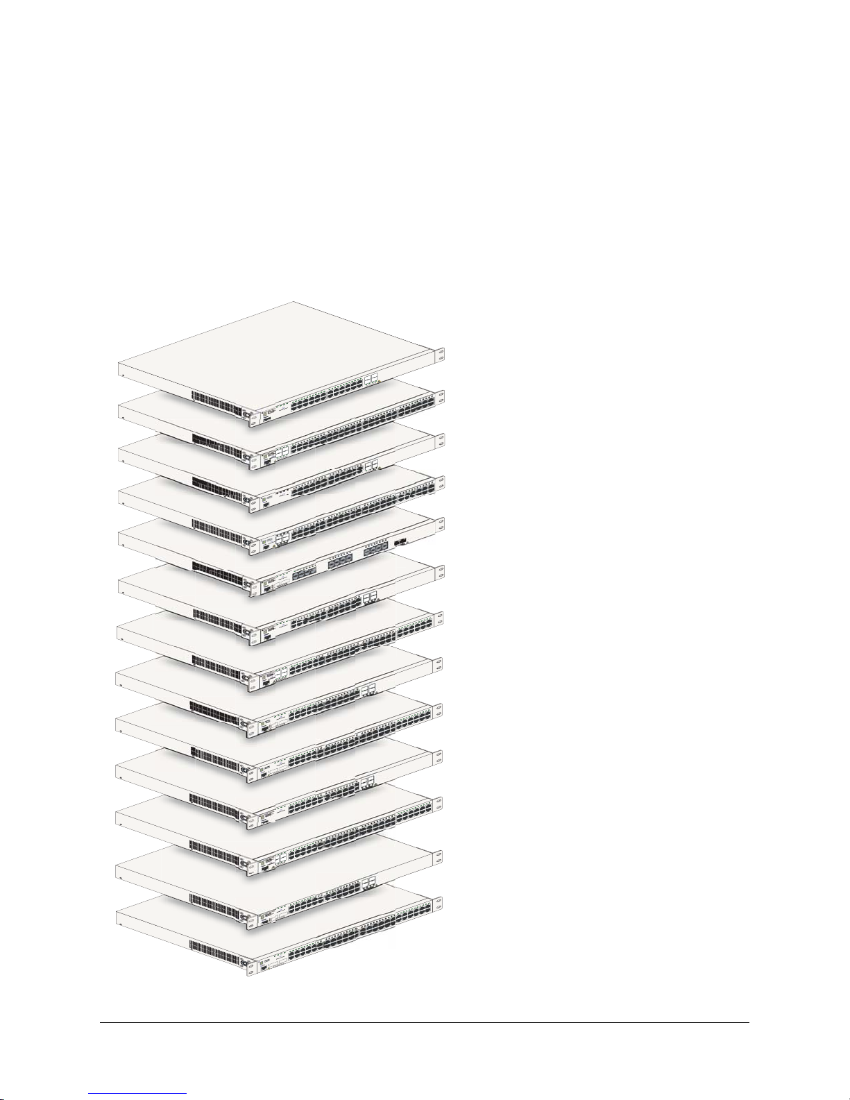
1 OmniSwitch 6850 Series
The OmniSwitch 6850 Series is an advanced fixed configuration family of Ethernet switches. These
switches provide wire rate layer-2 forwarding and layer-3 routing with advanced services.
OmniSwitch 6850-24L
22 23 24
1
24
23
UCT
19 20 2
OD
PR
22
R
E
AS
L
1
21
S
AS
12 13 14 15 16 17 18
8 9 10 11
5 6 7
1 2 3 4
BPS
PWR
PRI
OK
L
USB
OmniSwitch 6850-24
Console
PRI
OK
USB
OmniSwitch 6850-48L
2
1
CLASS 1 LASER PR
Console
PRI
OK
L
USB
OmniSwitch 6850-P24
Console
PRI
OK
L
USB
OmniSwitch 6850-P48
2
1
CLASS 1 LASER PR
Console
PRI
OK
X
USB
OmniSwitch 6850-U24
25
25
CLASS 1 LASER PR
26
Console
12 13 14
8 9 10 11
5 6 7
1 2 3 4
BPS
PWR
4
3
ODUCT
12 13 14 15 16 17 18
8 9 10 11
5 6 7
1 2 3 4
BPS
PWR
12 13 1
8 9 10 11
5 6 7
1 2 3 4
BPS
PWR
4
3
ODUCT
8
5 6 7
5 7
1 2 3 4
1 3
BPS
PWR
6 8
26
2 4
ODUCT
CL
29 30 31 32
26 27 28
23 24 25
19 20 21 22
15 16 17 18
24
23
19 20 21 22 23 24
ODUCT
22
21
CLASS 1 LASER PR
29 30 31 32
25 26 27 28
23 24
19 20 21 22
4 15 16 17 18
21 22 23
21 25
17 18 19 20
17 19
16
22 24
13 14 15
18 20
13 15
9 10 11 12
9 11
14 16
10 12
47 48
43 44 45 46
9 40 41 42
37 38 3
33 34 35 36
OmniSwitch 6850-48L
OmniSwitch 6850-P24L
46 47 48
43 44 45
39 40 41 42
37 38
33 34 35 36
OmniSwitch 6850-P48L
OmniSwitch 6850-U24X
24
24
ODUCT
23
CLASS 1 LASER PR
OmniSwitch 6850-24
BPS
PWR
PRI
OK
USB
OmniSwitch 6850-24
Console
BPS
PWR
PRI
OK
USB
OmniSwitch 6850-48
4
3
ODUCT
2
1
CLASS 1 LASER PR
Console
BPS
PWR
PRI
OK
X
26
USB
OmniSwitch 6850-24
25
ODUCT
25
CLASS 1 LASER PR
26
Console
BPS
PWR
PRI
OK
X
50
USB
OmniSwitch 6850-48
49
ODUCT
49
CLASS 1 LASER PR
50
Console
BPS
PWR
PRI
OK
USB
OmniSwitch 6850-P24
Console
BPS
PWR
PRI
OK
USB
OmniSwitch 6850-P48
4
3
ODUCT
2
1
CLASS 1 LASER PR
Console
BPS
PWR
PRI
OK
X
26
USB
OmniSwitch 6850-P24
25
ODUCT
25
CLASS 1 LASER PR
26
Console
BPS
PWR
PRI
OK
50
USB
OmniSwitch 6850-P48X
49
ODUCT
49
CLASS 1 LASER PR
50
Console
4 15 16 17 18
12 13 1
8 9 10 11
5 6 7
1 2 3 4
15 16 17 18 19 20 21
4 5 6 7 8 9 10 11 12 13 14
1 2 3
15 16 17 18
12 13 14
8 9 10 11
5 6 7
1 2 3 4
15 16 17 18 19 20 21
12 13 14
8 9 10 11
4 5 6 7
1 2 3
15 16 17 18
12 13 14
8 9 10 11
5 6 7
1 2 3 4
15 16 17 18 19 20 21
12 13 14
8 9 10 11
4 5 6 7
1 2 3
15 16 17 18
12 13 14
8 9 10 11
5 6 7
1 2 3 4
29 30 31 32
25 26 27 28
23 24
19 20 21 22
22 23 24
24
23
ODUCT
22
21
CLASS 1 LASER PR
29 30 31 32
26 27 28
23 24 25
19 20 21 22
22 23 24
24
23
ODUCT
22
21
CLASS 1 LASER PR
29 30 31 32
26 27 28
23 24 25
19 20 21 22
22 23 24
24
23
ODUCT
22
21
CLASS 1 LASER PR
29 30 31 32
26 27 28
23 24 25
19 20 21 22
46 47 48
43 44 45
39 40 41 42
37 38
33 34 35 36
OmniSwitch 6850-48
OmniSwitch 6850-24X
47 48
43 44 45 46
9 40 41 42
37 38 3
33 34 35 36
OmniSwitch 6850-48X
OmniSwitch 6850-P24
46 47 48
43 44 45
39 40 41 42
37 38
33 34 35 36
OmniSwitch 6850-P48
OmniSwitch 6850-P24X
47 48
43 44 45 46
9 40 41 42
37 38 3
33 34 35 36
OmniSwitch 6850-P48X
OmniSwitch 6850 Series Hardware Users Guide August 2007 page 1-1

OmniSwitch 6850 Series
• The OmniSwitch 6850-24L (OS6850-24L) is a 24-port, 10/100 fixed stackable chassis with four
combo fiber SFP connectors.
• The OmniSwitch 6850-48L (OS6850-48L) is a 48-port, 10/100 fixed stackable chassis with four
combo fiber SFP connectors.
• The OmniSwitch 6850-P24L (OS6850-P24L) is a 24-port, 10/100 PoE fixed stackable chassis with
four combo fiber SFP connectors.
• The OmniSwitch 6850-P48L (OS6850-P48L) is a 48-port, 10/100 PoE fixed stackable chassis with
four combo fiber SFP connectors.
• The OmniSwitch 6850-U24X (OS6850-U24X) is a 24-port, 1000Base-X SFP fixed stackable chassis
with two 10/100/1000 Base-T combo ports. This switch also includes two 10-Gigabit XFP connectors.
• The OmniSwitch 6850-24 (OS6850-24) is a 24-port, 10/100/1000 fixed stackable chassis with four
combo fiber SFP connectors.
• The OmniSwitch 6850-48 (OS6850-48) is a 48-port, 10/100/1000 fixed stackable chassis with four
combo fiber SFP connectors.
• The OmniSwitch 6850-24X (OS6850-24X) is a 24-port, 10/100/1000 fixed stackable chassis with four
combo fiber SFP connectors.This switch also includes two 10-Gigabit XFP connectors.
• The OmniSwitch 6850-48X (OS6850-48X) is a 48-port, 10/100/1000 fixed stackable chassis. This
switch also includes two 10-Gigabit XFP connectors.
• The OmniSwitch 6850-P24 (OS6850-P24) is a 24-port, 10/100/1000 PoE fixed stackable chassis with
four combo fiber SFP connectors.
• The OmniSwitch 6850-P48 (OS6850-P48) is a 48-port, 10/100/1000 PoE fixed stackable chassis with
four combo fiber SFP connectors.
• The OmniSwitch 6850-P24X (OS6850-P24X) is a 24-port, 10/100/1000 PoE fixed stackable chassis
with four combo fiber SFP connectors. This switch also includes two 10-Gigabit XFP connectors.
• The OmniSwitch 6850-P48X (OS6850-P48X) is a 48-port, 10/100/1000 PoE fixed stackable chassis.
This switch also includes two 10-Gigabit XFP connectors.
The OmniSwitch 6850 Series switches offer effective availability, resiliency, and security features and are
ideal for the following network applications:
• Enterprise workgroups/LAN wiring closets
• Edge deployments and branch offices
• L3 aggregation/distribution layer switches in three-tier networks
• Small enterprise core switching
• Quality of service (QoS) for mission critical applications
• Data center server clusters
page 1-2 OmniSwitch 6850 Series Hardware Users Guide August 2007

OmniSwitch 6850 Series Availability Features
Availability Features
The switch provides a broad variety of availability features. Availability features are hardware and
software-based safeguards that help to prevent the loss of data flow in the unlikely event of a subsystem
failure. In addition, some availability features allow users to maintain or replace hardware components
without powering off the switch or interrupting switch operations. Combined, these features provide added
resiliency and help to ensure that the switch or virtual chassis is consistently available for day-to-day
network operations.
Hardware-related availability features include:
• Software Rollback
• Backup Power Supplies
• Hot Swapping
• Hardware Monitoring
Software Rollback
Software rollback (also referred to as image rollback) essentially allows the OmniSwitch 6850 Series
switches to return to a prior “last known good” version of software in the event of a system software problem. The switch controls software rollback through its resilient directory structure design (i.e., /flash/
working and /flash/certified).
For detailed information on the software rollback feature, as well as the switch’s /flash/working and
/flash/certified directories, refer to the “Managing CMM Directory Content” chapter in the OmniSwitch
6800/6850/9000 Series Switch Management Guide.
Backup Power Supplies
The OmniSwitch 6850 Series switches support an optional backup power supply. This power supply is
connected to the rear of the unit. There is a power shelf provided with the unit that slides into the rear of
the chassis and is used to hold the power supplies. It can hold 510W or 360W power supply or in case of
non-PoE product switches 120W or 126W power supply. This provides redundant chassis power on a 1:1
basis.
Backup power supplies operate in active standby mode. If the primary power supply fails unexpectedly,
the backup power supply automatically takes up the full power load without disrupting the switch.
Note. For more information on backup power supplies, refer to Chapter 2, “OmniSwitch 6850 Series
Chassis and Hardware Components.”
OmniSwitch 6850 Series Hardware Users Guide August 2007 page 1-3

Availability Features OmniSwitch 6850 Series
Hot Swapping
Hot swapping refers to the action of adding, removing, or replacing components without powering off
switches or disrupting other components.This feature facilitates hardware upgrades and maintenance and
allows users to easily replace components in the unlikely event of hardware failure.
The following hardware components can be hot swapped:
• Backup power supply
• Backup power supply connector cables
• SFPs
For instructions on hot swapping backup power supplies, refer to Chapter 2, “OmniSwitch 6850 Series
Chassis and Hardware Components.” For instructions on hot swapping combo connector SFPs, refer to the
instruction card provided with the SFP product.
Hardware Monitoring
Automatic Monitoring
Automatic monitoring refers to the switch’s built-in sensors that automatically monitor operations. If an
error is detected (e.g., over-threshold temperature), the switch immediately sends a trap to the user. The
trap is displayed on the console in the form of a text error message. (In the case of an over-threshold
temperature condition, the chassis displays an amber TMP LED in addition to sending a trap.)
LEDs
LEDs, which provide visual status information, are provided on the chassis front panel. LEDs are used to
indicate conditions such as hardware and software status, temperature errors, link integrity, data flow, etc.
For detailed LED descriptions, refer to Chapter 2, “OmniSwitch 6850 Series Chassis and Hardware
Components.”
User-Driven Monitoring
User-driven hardware monitoring refers to CLI commands that are entered by the user in order to access
the current status of hardware components. The user enters “show” commands that output information to
the console. Monitoring information for chassis components, such as the optional back up power supply,
chassis temperature sensor, and chassis fans is provided in Chapter 2, “OmniSwitch 6850 Series Chassis
and Hardware Components.” The show commands for all the features are described in detail in the
OmniSwitch CLI Reference Guide.
page 1-4 OmniSwitch 6850 Series Hardware Users Guide August 2007
OmniSwitch 6850 Series OmniSwitch 6850 Series Application Examples
OmniSwitch 6850 Series Application Examples
The following OmniSwitch 6850 Series applications are described below:
• Gigabit-to-the-desktop migration
• Server aggregation
• Layer 3 Aggregation/Distribution
• Small Enterprise core
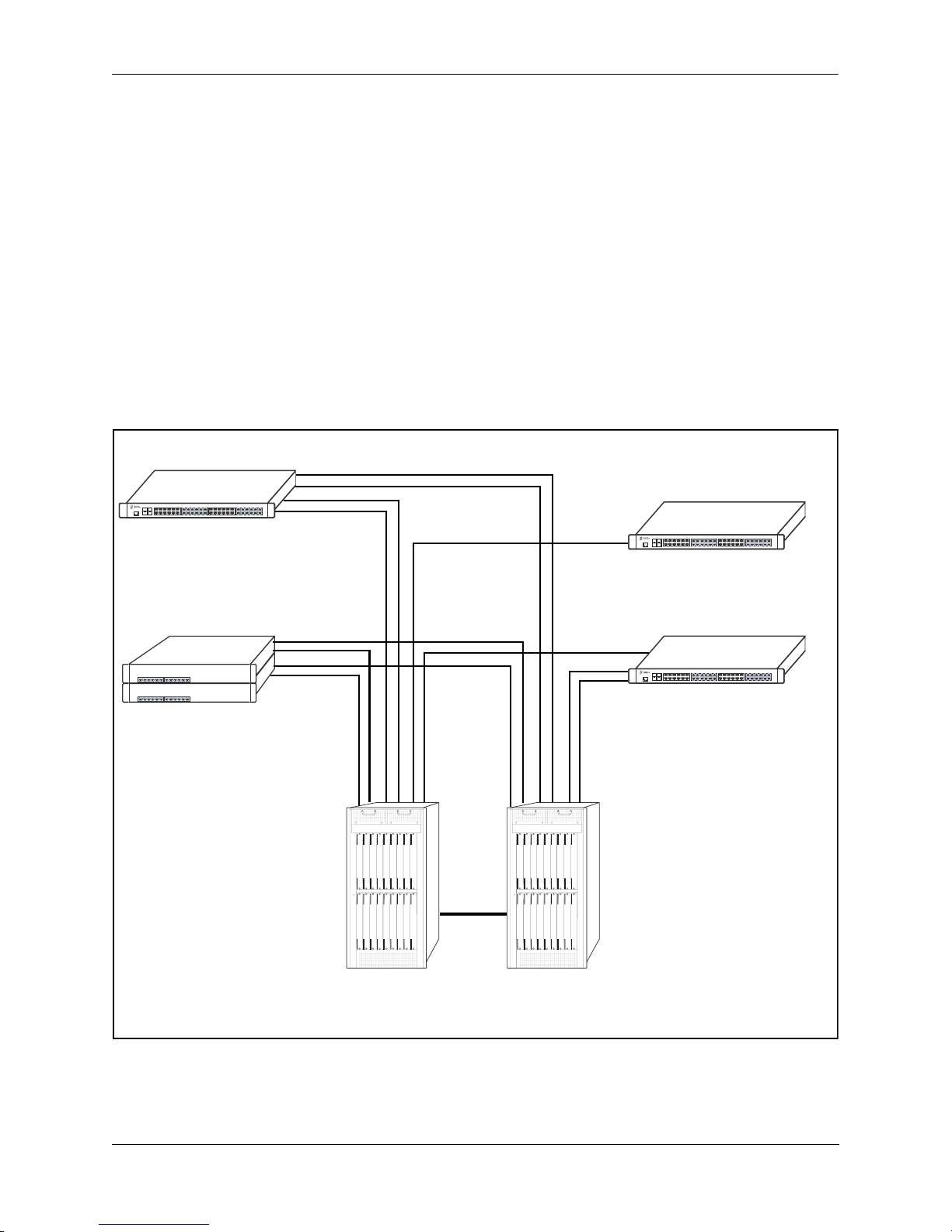
Gigabit-to-the-Desktop Migration
The OmniSwitch 6850 Series switches provide a migration path to Gigabit on the edge of the LAN.
For example:
10/100/1000 Layer 2+ Switching
10/100/1000 Layer 3 Switching
OmniSwitch 6850
Layer 2+ 10/100 Switching
Core Layer
OmniSwitch 8800
OmniSwitch 6850
OmniSwitch 6850
OmniSwitch 8800
Application Example: Gigabit-to-the-Desktop Migration
OmniSwitch 6850 Series Hardware Users Guide August 2007 page 1-5
OmniSwitch 6850 Series Application Examples OmniSwitch 6850 Series
Server Aggregation
The OmniSwitch 6850 Series switch is a well-suited server aggregation switch, especially for
space-constrained data centers, where the switch can be installed in the same rack as the servers. For
example:
10/100/1000 Switching
10/100/1000 Switching
OmniSwitch 6850
Servers
Application Example: Server Aggregation
page 1-6 OmniSwitch 6850 Series Hardware Users Guide August 2007
OmniSwitch 6850 Series OmniSwitch 6850 Series Application Examples
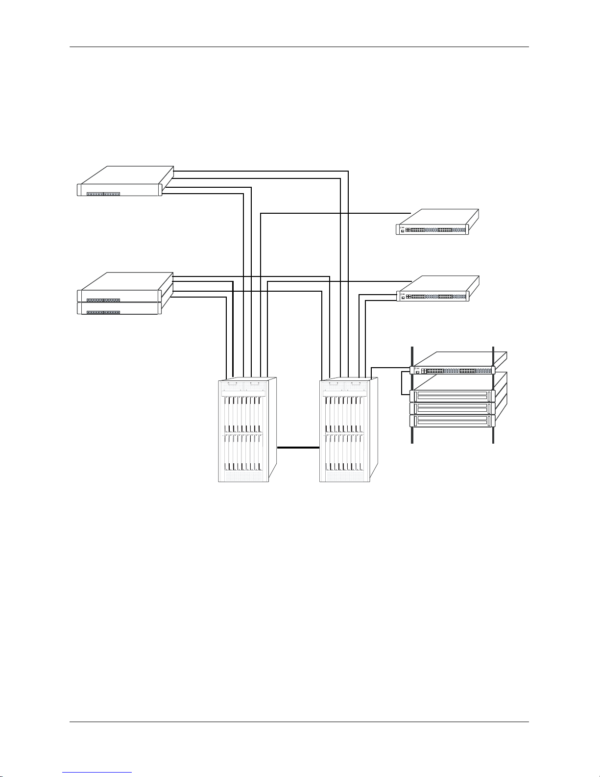
Layer 3 Aggregation/Distribution
The OmniSwitch 6850 Series switches placed in the distribution layer of three-tier networks provide highcapacity, wire speed Layer 2 switching, Layer 3 routing, and intelligent services near the edge of the
network. For example:
10/100 Switching
Gigabit
Uplinks
Aggregation Layer
(L2/L3 Switching)
OmniSwitch 6850
Multiple
1 Gig
10 Gig
10 Gig
OmniSwitch 6850
10 Gig
Core Layer
(L3)
Application Example: Layer 3 Aggregation/Distribution
OmniSwitch 6850 Series Hardware Users Guide August 2007 page 1-7
OmniSwitch 6850 Series Application Examples OmniSwitch 6850 Series
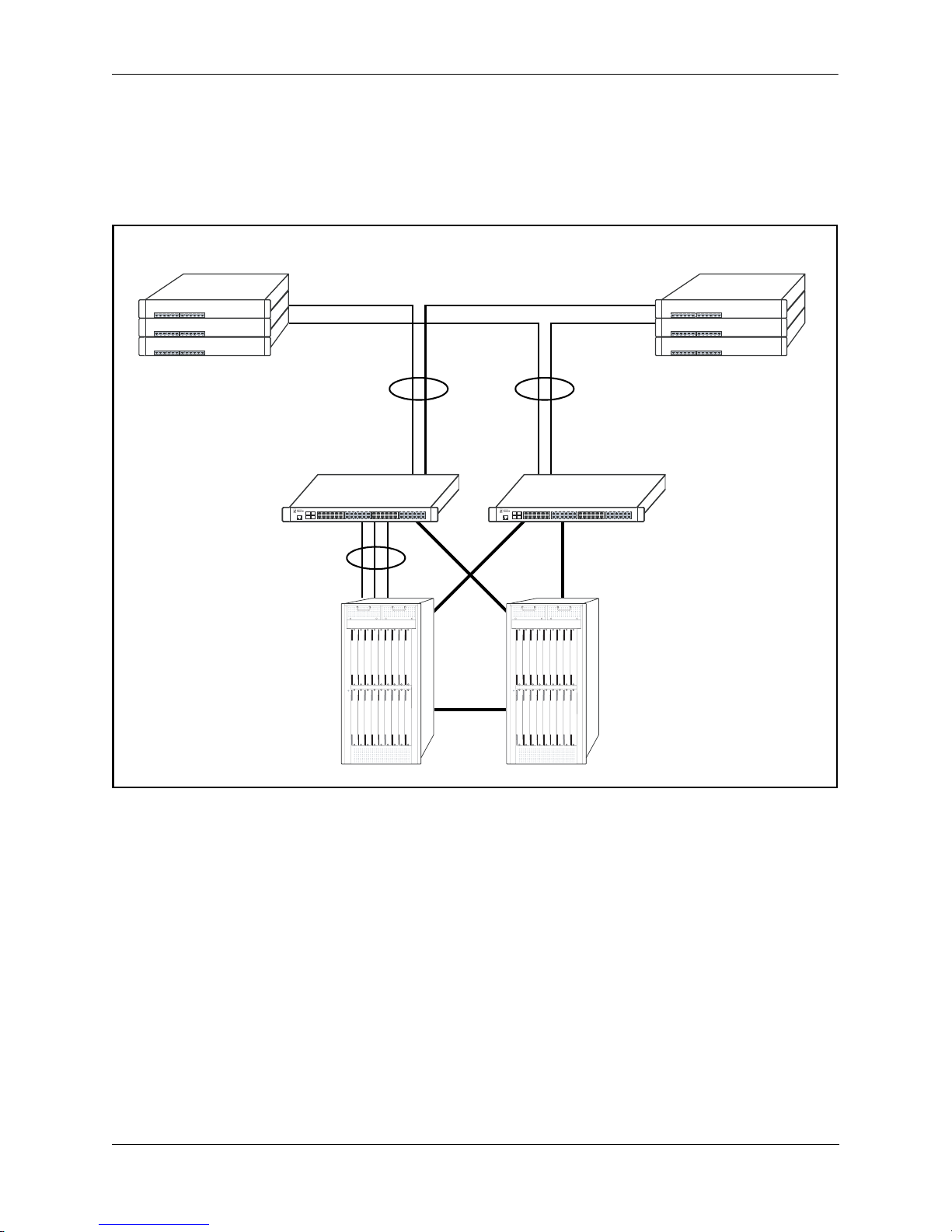
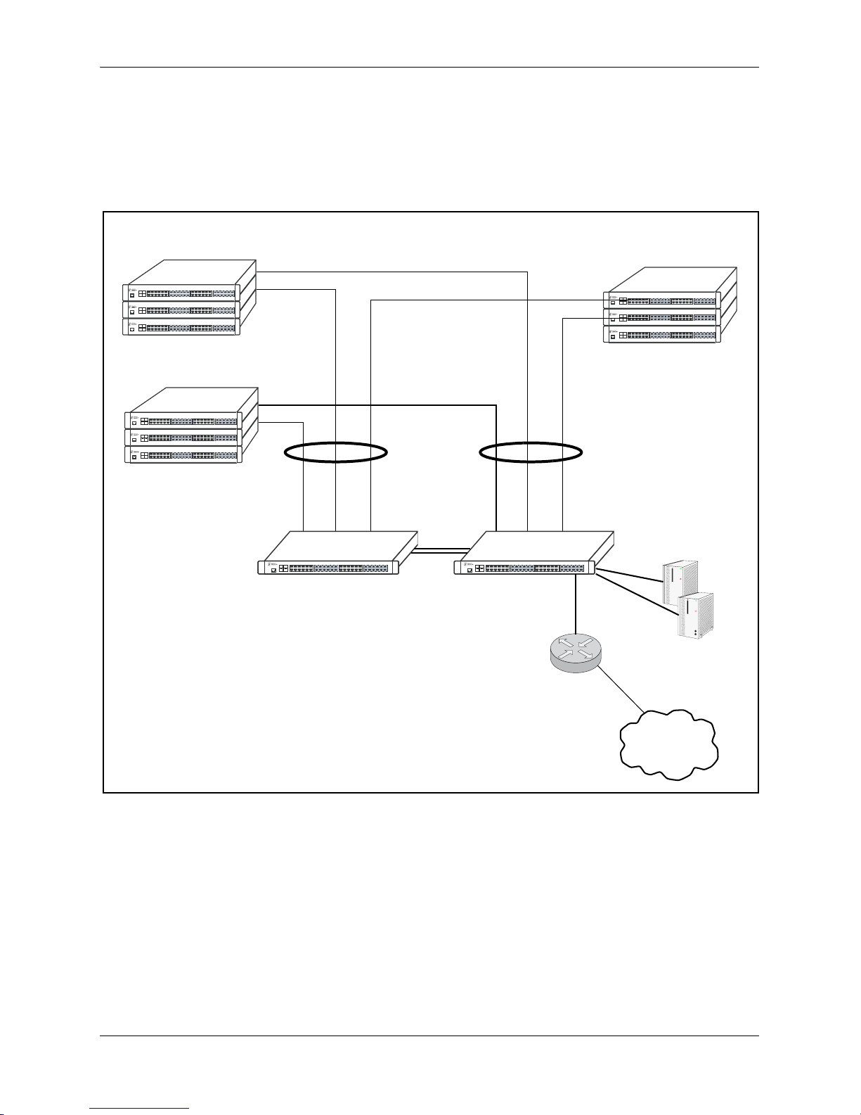
Small Enterprise Core
With its high-speed switching capacity, supported Layer 3 routing protocols, advanced network services,
and wire speed 10 Gigabit capability, the OmniSwitch 6850 Series provides effective core switching for
smaller Enterprise networks (200-500 ports). For example:
10/100 layer 2 Switching
10/100 layer 2 Switching
OmniSwitch 6850
Series Switch
Gigabit Layer 3 Switching
Gigabit Uplinks
OmniSwitch 6850
Series Switch
Internet
Router
10/100 layer 2 Switching
Servers
Internet
Application Example: Small Enterprise Core
page 1-8 OmniSwitch 6850 Series Hardware Users Guide August 2007

2 OmniSwitch 6850 Series
Chassis and Hardware
Components
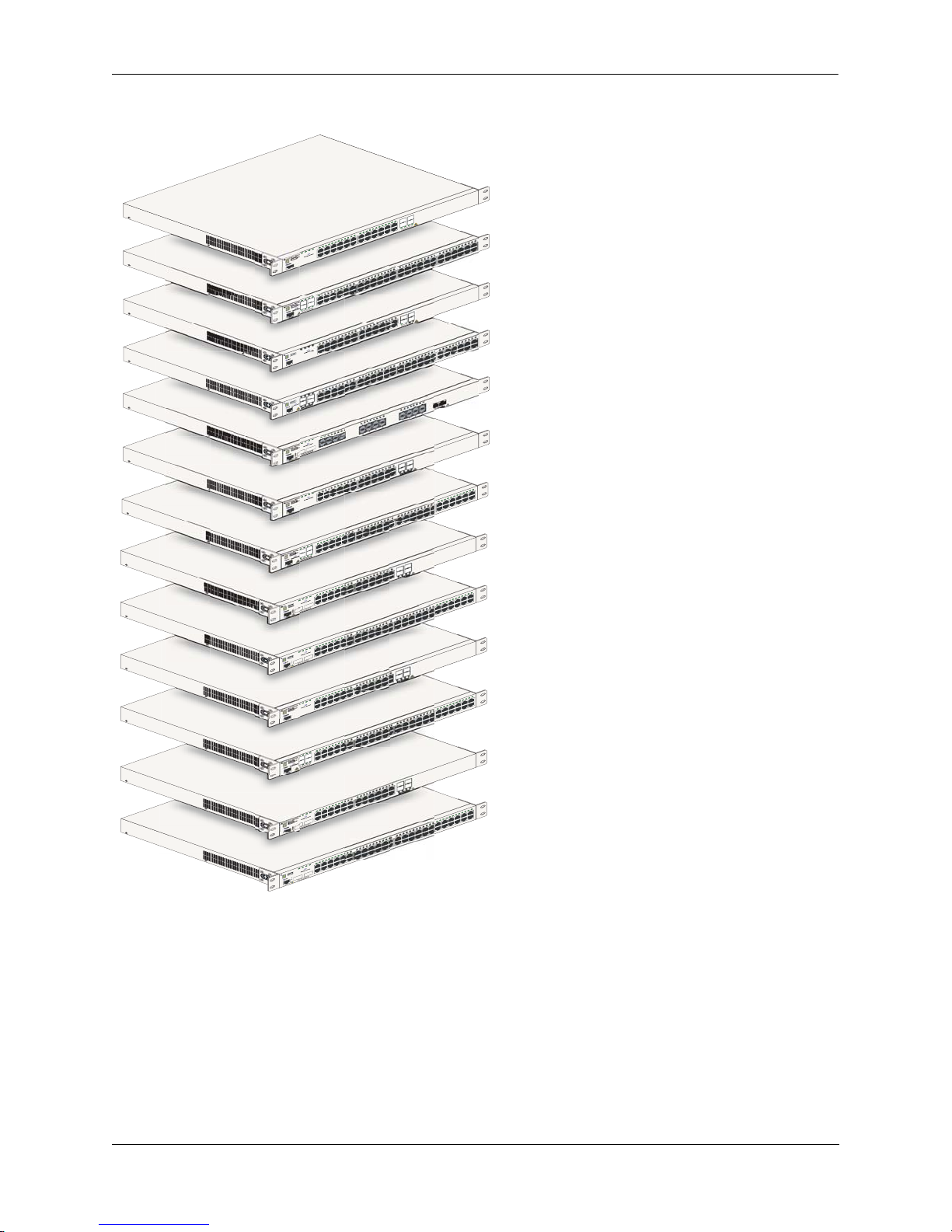
OmniSwitch 6850 Series switches are available in thirteen stackable chassis configurations as shown in
the table below:
• OmniSwitch 6850-24L
(OS6850-24L)
• OmniSwitch 6850-48L
(OS6850-48L)
• OmniSwitch 6850-P24L
(OS6850-P24L)
• OmniSwitch 6850-P48L
(OS6850-P48L)
• OmniSwitch 6850-U24X
(OS6850-U24X)
• OmniSwitch 6850-24
(OS6850-24)
• OmniSwitch 6850-48
(OS6850-48)
• OmniSwitch 6850-24X
(OS6850-24X)
• OmniSwitch 6850-48X
(OS6850-48X)
• OmniSwitch 6850-P24
(OS6850-P24)
24-port 10/100
48-port 10/100
24-port 10/100 Power over Ethernet (PoE)
48-port 10/100 Power over Ethernet (PoE)
24-port Gigabit SFP with 10 Gigabit uplinks
24-port 10/100/1000
48-port 10/100/1000
24-port with 10 Gigabit uplinks
48-port with 10 Gigabit uplinks
24-port 10/100/1000 Power over Ethernet (PoE)
• OmniSwitch 6850-P48
(OS6850-P48)
• OmniSwitch 6850-P24X
(OS6850-P24X)
• OmniSwitch 6850-P48X
(OS6850-P48X)
OmniSwitch 6850 Series Hardware Users Guide August 2007 page 2-1
48-port 10/100/1000 Power over Ethernet (PoE)
24-port PoE with 10 Gigabit uplinks
48-port PoE with 10 Gigabit uplinks

OmniSwitch 6850 Series Chassis and Hardware Components
This chapter includes detailed information on these chassis types. Topics include:
• OmniSwitch 6850 Series chassis descriptions
• Technical specifications
• Switch mounting
• Booting OmniSwitch 6850 Series switches
• Power cords, console port, and pinout specifications
• OmniSwitch 6850 Series power supplies
• Monitoring the chassis
page 2-2 OmniSwitch 6850 Series Hardware Users Guide August 2007
OmniSwitch 6850 Series Chassis and Hardware Components
4
2
3
2
22
21
0
24
2
T
23
19
UC
OD
8
2
1
2
R PR
SE
A
L
17
21
SS 1
A
L
C
16
15
14
13
2
1
1
1
10
9
8
7
6
5
4
3
2
1
S
BP
WR
P
RI
P
K
O
L
USB
OmniSwitch 6850-24
sole
n
Co
4
3
2
1
PS
B
R
PW
I
R
P
OK
USB
OmniSwitch 6850-48L
4
T
3
C
U
OD
PR
2
R
SE
A
L
1
CLASS 1
e
onsol
C
4
1 2 3
PS
B
PWR
PRI
OK
L
B
S
U
OmniSwitch 6850-P24
onsole
C
1 2 3 4
BPS
PWR
PRI
OK
L
USB
OmniSwitch 6850-P48
4
T
3
C
U
OD
PR
2
SER
A
1 L
1
CLASS
Console
1 2 3
1 3
BPS
PWR
PRI
OK
X
26
2 4
USB
OmniSwitch 6850-U24
25
ODUCT
R
P
ER
S
A
L
25
SS 1
CLA
26
Console
BPS
PWR
PRI
OK
USB
OmniSwitch 6850-24
Console
5 6 7
1 2 3 4
BPS
PWR
PRI
OK
USB
OmniSwitch 6850-48
4
3
ODUCT
2
1
CLASS 1 LASER PR
Console
1 2 3 4 5 6 7
BPS
PWR
PRI
OK
X
26
USB
OmniSwitch 6850-24
25
ODUCT
25
CLASS 1 LASER PR
26
Console
5 6 7
1 2 3 4
BPS
PWR
PRI
OK
X
50
USB
OmniSwitch 6850-48
49
ODUCT
49
CLASS 1 LASER PR
50
Console
4 5 6 7
1 2 3
BPS
PWR
PRI
OK
USB
OmniSwitch 6850-P24
Console
5 6 7
1 2 3 4
BPS
PWR
PRI
OK
USB
OmniSwitch 6850-P48
4
3
ODUCT
PR
2
1
CLASS 1 LASER
Console
4 5 6 7
1 2 3
BPS
PWR
PRI
OK
X
26
USB
OmniSwitch 6850-P24
25
ODUCT
25
CLASS 1 LASER PR
26
Console
5 6 7
1 2 3 4
BPS
PWR
PRI
OK
50
USB
OmniSwitch 6850-P48X
49
49
CLASS 1 LASER PRODUCT
50
Console
5
5 6 7
5
4
6
6 7
5 6 7
5 7
6 8
7
8 9 10 11 12 13 14
8 9 10 11
8 9 10 11
8 9 10 11
8 9 10 11
8 9 10 11
9
8
8 9 10 11
8 9
8
8 9 10 11
14
3
1
2
1
1
0 1
1
12 13 14 15 16 17 18 19 20 21 22
1
12 13
11
10
9 10 11 12
4 15 16 17 18
12 13 1
15 16 17
15 16 17 18
12 13 14
15 16 17 18 19 20 21
12 13 14
15 16 17 18
12 13 14
15 16 17
12 13 14
15 16 17 18
12 13 14
19
8
1
7
1
16
15
19
4 15 16 17 18
13 14 15
13 15
11
9
14 16
10 12
19 20 21 22
18 19 20 21
19 20 21 22
19 20 21 22
18 19 20 21
19 20 21 22
3
3
32
31
30
9
2
8
2
27
26
5
2
24
23
2
2
21
20
23 24
24
T
23
UC
D
O
22
R PR
E
AS
1 L
21
SS
A
L
C
33
31 32
30
29
25 26 27 28
23 24
21 22
20
24
21 22 23
21 25
17 18 19 20
17 19
16
22 24
18 20
33 34 35 36
29 30 31 32
25 26 27 28
23 24
22 23 24
24
23
ODUCT
22
21
CLASS 1 LASER PR
33 34 35 36
29 30 31 32
26 27 28
23 24 25
22 23 24
24
23
ODUCT
22
21
CLASS 1 LASER PR
33 34 35 36
26 27 28 29 30 31 32
23 24 25
22 23 24
24
23
ODUCT
22
21
CLASS 1 LASER PR
33 34 35 36
29 30 31 32
26 27 28
23 24 25
48
47
6
4
5
4
44
3
4
40 41 42
9
3
38
37
6
3
5
3
34
48
46 47
45
43 44
41 42
40
39
8
3
37
36
34 35
24
UCT
D
O
R
P
R
23
LASE
1
S
S
CLA
46 47 48
43 44 45
39 40 41 42
37 38
47 48
43 44 45 46
9 40 41 42
37 38 3
46 47 48
43 44 45
39 40 41 42
37 38
47 48
43 44 45 46
9 40 41 42
37 38 3
OmniSwitch 6850-24L
OmniSwitch 6850-48L
OmniSwitch 6850-P24L
OmniSwitch 6850-P48L
OmniSwitch 6850-U24X
OmniSwitch 6850-24
OmniSwitch 6850-48
OmniSwitch 6850-24X
OmniSwitch 6850-48X
OmniSwitch 6850-P24
OmniSwitch 6850-P48
OmniSwitch 6850-P24X
OmniSwitch 6850-P48X
OmniSwitch 6850 Series Hardware Users Guide August 2007 page 2-3

OmniSwitch 6850-24L OmniSwitch 6850 Series Chassis and Hardware Components
OmniSwitch 6850-24L
The OmniSwitch 6850-24L is a stackable edge/workgroup switch offering 20 unshared 10/100Base-T, as
well as four combo individually configurable to be 10/100/1000Base-T or 1000Base-X
high-speed connections.
The front panel of the OS6850-24L chassis contains the following major components:
• System status and slot indicator LEDs
• (20) unshared 10/100Base-T
• (4) shared combo 10/100/1000Base-T
• (4) Combo SFP connectors for 1000Base-X connections
• Console port (RJ-45)
• USB port (USB 2.0)
Note. USB 2.0 is not supported in this release.
Note. The 20 (non-combo) 10/100Base-T on the OmniSwitch 6850-24L can be upgraded to
10/100/1000Base-T. Please contact your Alcatel-Lucent representative for more information.
page 2-4 OmniSwitch 6850 Series Hardware Users Guide August 2007
OmniSwitch 6850 Series Chassis and Hardware Components OmniSwitch 6850-24L
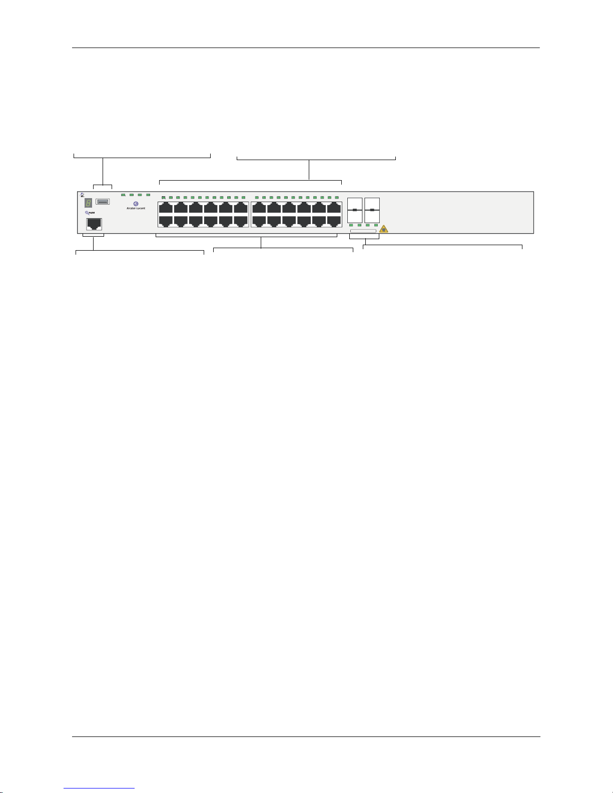
Refer to the illustration below for more front panel information. For detailed LED descriptions, refer to
page 2-54. For information on the chassis rear panel, refer to page 2-56.
Status and Slot Indicator LEDs
USB Port
High speed USB 2.0 port, which
can be used for quick upgrades.
PRI PWR BPS
OmniSwitch 6850-24L
Console
OK
USB
1 2 3 4 5 6 7 8 9 10 11 12 13 14 15 16 17 18 19 20 21 22 23 24
For information on the OS6850-24L’s
status and slot indicator LEDs, refer to
page 2-54.
21 22 23 24
CLASS 1 LASER PRODUCT
Console Port
The OS6850-24L front panel
provides one RJ-45 port for console connections. Console connections are used by network
administrators for switch management. This female RJ-45 connector provides a DTE console
connection.
10/100 Mbps and 10/100/1000Mbps
The OS6850-24L provides 20 fixed
10/100BaseT non-combo (1–20) and 4
fixed
10/100/1000BaseT combo 21–24).
These are auto-sensing and auto-MDIX
and use RJ-45 connectors.
OmniSwitch 6850-24L Front Panel
Combo SFP
The OS6850-24L provides four combo
SFP connectors for 1000Base-X highspeed connections.
By default, when an SFP is installed in a
combo port, it takes over the port number
of the corresponding RJ-45 Ethernet port.
In other words, if an SFP is installed in
the slot labeled 24, Ethernet port 24
would no longer be available and cannot
be used for 10/100/1000 traffic. This
default setting is referred to as “preferred
fiber.” Refer to “Configuring Ethernet” in
Network Configuration Guide for
the
detailed information, including
steps for
configuring combo port settings.
OmniSwitch 6850 Series Hardware Users Guide August 2007 page 2-5

OmniSwitch 6850-24L OmniSwitch 6850 Series Chassis and Hardware Components
OS6850-24L Specifications
Total unshared
20
10/100Base-T per switch (1–20)
Total shared 10/100/1000Base-T
4
combo per switch
(21–24)
Total combo 1000Base-X
4
combo SFP connectors per
switch (21–24)
Total 10/100Base-T per stack 160 (stack of eight switches)
Total combo SFP connectors per
32 (stack of eight switches)
stack
Power 126/120W (AC/DC) power supply
Flash memory size 64 MB
RAM memory size 256 MB SDRAM
Overall Width (rack-mount
19 inches, approx.
flanges included)
Chassis Width (rack-mount
17.5 inches
flanges not included)
Height 1.73 inches
Height (rack units) 1 RU
Chassis Depth 10.5 inches without power supplies installed;
16.75 inches with power supplies installed
Weight 14 lbs (6.24 Kg), approx.
Humidity 5% to 90% Relative Humidity (Operating)
0% to 95% Relative Humidity (Storage)
Operating Temperature 0 to 45 degrees, Celsius
Storage Temperature -20 to 70 degrees, Celsius
Altitude Operating altitude: sea level at 40 degrees, Celsius and
10000 feet at 0 degrees, Celsius
Storage altitude: sea level to 40000 feet
Standards supported 802.3z, 802.3ab, 1000Base-T, IEEE 802.3u
Data rate (RJ-45) 10 or 100 Mbps (full or half duplex)
1 Gigabit per second (full duplex)
Data rate (SFP) 1 Gigabit per second (full duplex)
Maximum frame size 9216 bytes
Connections supported 10/100/1000Base-T and 1000Base-X
Cable supported
(RJ-45)
10BaseT: unshielded twisted-pair (UTP)
100BaseTX: unshielded twisted-pair (UTP), Category 5, EIA/TIA 568
or shielded twisted-pair (STP), Category 5, 100 ohm
1000BaseT: unshielded twisted-pair (UTP), Category 5e
page 2-6 OmniSwitch 6850 Series Hardware Users Guide August 2007
 Loading...