

Page 1

Part No. 060209-10, Rev. E
August 2007
OmniSwitch 6850 Series
Hardware Users Guide
www.alcatel-lucent.com
Page 2

This user guide documents OmniSwitch 6850 Series hardware, including
chassis and associated components.
The specifications described in this guide are subject to change without notice.
Copyright © 2007 by Alcatel-Lucent. All rights reserved. This document may not be reproduced in whole
or in part without the express written permission of Alcatel-Lucent.
®
Alcatel-Lucent
OmniSwitch
and the Alcatel-Lucent logo are registered trademarks of Alcatel-Lucent. Xylan®,
®
, OmniStack®, and Alcatel-Lucent OmniVista® are registered trademarks of Alcatel-Lucent.
OmniAccess™, Omni Switch/Router™, PolicyView™, RouterView™, SwitchManager™, VoiceView™,
WebView™, X-Cell™, X-Vision™, and the Xylan logo are trademarks of Alcatel-Lucent.
This OmniSwitch product contains components which may be covered by one or more of the following
U.S. Patents:
•U.S. Patent No. 6,339,830
•U.S. Patent No. 6,070,243
•U.S. Patent No. 6,061,368
•U.S. Patent No. 5,394,402
•U.S. Patent No. 6,047,024
•U.S. Patent No. 6,314,106
•U.S. Patent No. 6,542,507
•U.S. Patent No. 6,874,090
26801 West Agoura Road
Calabasas, CA 91301
(818) 880-3500 FAX (818) 880-3505
support@ind.alcatel.com
US Customer Support—(800) 995-2696
International Customer Support—(818) 878-4507
Internet—service.esd.alcatel-lucent.com
ii OmniSwitch 6850 Series Hardware Users Guide August 2007
Page 3

Contents
About This Guide ..........................................................................................................ix
Supported Platforms .......................................................................................................... ix
Who Should Read this Manual? ........................................................................................xi
When Should I Read this Manual? ....................................................................................xi
What is in this Manual? ..................................................................................................... xi
What is Not in this Manual? ..............................................................................................xi
How is the Information Organized? .................................................................................xii
Documentation Roadmap .................................................................................................xii
Related Documentation ...................................................................................................xiv
User Manual CD ..............................................................................................................xv
Technical Support ............................................................................................................ xv
Chapter 1 OmniSwitch 6850 Series ...........................................................................................1-1
Availability Features .......................................................................................................1-3
Software Rollback ....................................................................................................1-3
Backup Power Supplies ............................................................................................1-3
Hot Swapping ...........................................................................................................1-4
Hardware Monitoring ...............................................................................................1-4
OmniSwitch 6850 Series Application Examples ............................................................1-5
Gigabit-to-the-Desktop Migration ............................................................................1-5
Server Aggregation ..................................................................................................1-6
Layer 3 Aggregation/Distribution ............................................................................1-7
Small Enterprise Core ..............................................................................................1-8
Chapter 2 OmniSwitch 6850 Series Chassis and Hardware Components .....................2-1
OmniSwitch 6850-24L ....................................................................................................2-4
OmniSwitch 6850-48L ....................................................................................................2-8
OmniSwitch 6850-P24L ................................................................................................2-11
OmniSwitch 6850-P48L ................................................................................................2-15
OmniSwitch 6850-U24X ..............................................................................................2-19
OmniSwitch 6850-24 ....................................................................................................2-23
OmniSwitch 6850-48 ....................................................................................................2-27
OmniSwitch 6850-24X .................................................................................................2-31
OmniSwitch 6850-48X .................................................................................................2-35
OmniSwitch 6850-P24 ..................................................................................................2-38
OmniSwitch 6850 Series Hardware Users Guide August 2007 iii
Page 4

Contents
OmniSwitch 6850-P48 ..................................................................................................2-42
OmniSwitch 6850-P24X ...............................................................................................2-46
OmniSwitch 6850-P48X ...............................................................................................2-50
Status LEDs ...................................................................................................................2-54
10/100/1000 LEDs .................................................................................................2-55
100/1000 SFP LEDs ...............................................................................................2-55
10000 XFP1 LEDs .................................................................................................2-55
10000 XFP2 LEDs .................................................................................................2-55
Rear Panel .....................................................................................................................2-56
Mounting the Switch .....................................................................................................2-57
Airflow Considerations ..........................................................................................2-57
Chassis Airflow ...............................................................................................2-58
Blank Cover Panels ................................................................................................2-59
Installation Options ................................................................................................2-60
Installing the Switch on a Tabletop or Bench .................................................2-60
Rack-Mounting the Switch ..............................................................................2-61
Installing and Removing Combo Port SFPs ...........................................................2-62
Setting Up a Stacked Configuration ..............................................................................2-63
Rack Mounting Stacked Configurations ................................................................2-63
Cabling Stacked Configurations .............................................................................2-63
Redundant Stacking Cable Connections .........................................................2-63
Supported Cabling Patterns .............................................................................2-63
Booting OmniSwitch 6850 Series Switches .................................................................2-66
Booting a Stand-Alone Switch ...............................................................................2-66
Booting Stacked Configurations ............................................................................2-67
Power Cords ..................................................................................................................2-68
Specifications .........................................................................................................2-68
Console Port ..................................................................................................................2-69
Serial Connection Default Settings ........................................................................2-69
Modifying the Serial Connection Settings .............................................................2-69
Console Port Pinouts ..............................................................................................2-71
10/100 Ethernet Port – RJ-45 Pinout (non-PoE) .............................................2-71
Gigabit Ethernet Port – RJ-45 Pinout ..............................................................2-71
10/100/1000 Mbps Power over Ethernet Port – RJ-45 Pinout .......................2-71
RJ-45 Console Port – Connector Pinout ..........................................................2-72
OmniSwitch 6850 Series Power Supplies .....................................................................2-73
Power Supply Shelf ................................................................................................2-75
PS-510W-AC Power Supply ..................................................................................2-76
PS-360W-AC Power Supply ..................................................................................2-77
PS-126W-AC Power Supply ..................................................................................2-78
PS-120W-DC Power Supply ..................................................................................2-79
Installing Power Supplies .......................................................................................2-80
Connecting a Power Supply Directly to the Chassis .......................................2-80
Connecting a Power Supply with a Cable .......................................................2-81
DC Power Supply Considerations ...................................................................2-85
Viewing the Power Supply Status ...................................................................2-86
iv OmniSwitch 6850 Series Hardware Users Guide August 2007
Page 5

Contents
Monitoring the Chassis .................................................................................................2-87
Checking the Overall Chassis Status ......................................................................2-87
Checking the Temperature Status ..........................................................................2-87
Checking the Fan Status .........................................................................................2-88
Checking the Power Supply Status ........................................................................2-88
Additional Monitoring Commands ........................................................................2-88
Using LEDs to Visually Monitor the Chassis ........................................................2-89
Installing SFP and XFP Transceivers .....................................................................2-89
2-89
Chapter 3 Installing and Managing Power over Ethernet (PoE) ......................................3-1
In This Chapter ................................................................................................................3-2
Power over Ethernet Specifications ................................................................................3-3
Viewing PoE Power Supply Status .................................................................................3-4
Configuring Power over Ethernet Parameters .................................................................3-5
Power over Ethernet Defaults ..................................................................................3-5
Understanding and Modifying the Default Settings .................................................3-5
Setting the PoE Operational Status ....................................................................3-5
Configuring the Total Power Allocated to a Port ..............................................3-6
Configuring the Total Power Allocated to a Switch .........................................3-6
Setting Port Priority Levels ...............................................................................3-7
Setting the Capacitor Detection Method ...........................................................3-8
Understanding Priority Disconnect .................................................................................3-9
Setting Priority Disconnect Status ............................................................................3-9
Disabling Priority Disconnect ...........................................................................3-9
Enabling Priority Disconnect ............................................................................3-9
Priority Disconnect is Enabled; Same Priority Level on All PD .....................3-10
Priority Disconnect is Enabled; Incoming PD Port has Highest
Priority Level ...................................................................................................3-10
Priority Disconnect is Enabled; Incoming PD Port has Lowest
Priority Level ...................................................................................................3-10
Priority Disconnect is Disabled .......................................................................3-11
Monitoring Power over Ethernet via CLI .....................................................................3-12
Chapter 4 Managing OmniSwitch 6850 Series Stacks ........................................................4-1
In This Chapter ................................................................................................................4-2
OmniSwitch 6850 Series Stack Overview ......................................................................4-3
Roles Within the Stack ....................................................................................................4-3
Primary and Secondary Management Modules .......................................................4-3
Primary Management Module Selection ...........................................................4-6
Secondary Management Module Selection .......................................................4-9
Idle Module Role ....................................................................................................4-11
Pass-Through Mode ...............................................................................................4-12
Recovering from Pass-Through Mode (Duplicate Slot Numbers) ..................4-13
Stack Cabling ................................................................................................................4-16
Redundant Stacking Cable Connection ..................................................................4-17
Checking Redundant Stacking Cable Status ..........................................................4-18
OmniSwitch 6850 Series Hardware Users Guide August 2007 v
Page 6

Contents
Slot Numbering .............................................................................................................4-19
Dynamic Slot Number Assignment ........................................................................4-20
Manual Slot Number Assignment ..........................................................................4-22
Reverting to the Dynamic Slot Numbering Model ..........................................4-23
Hot-Swapping Modules In a Stack ...............................................................................4-24
Removing Switches from an Existing Stack ..........................................................4-24
Inserting Switches Into an Existing Stack ..............................................................4-24
Merging Stacks .......................................................................................................4-25
Reloading Switches .......................................................................................................4-26
Reloading the Primary Management Module ........................................................4-26
Reloading the Secondary Management Module ....................................................4-28
Reloading Switches with Idle Roles .......................................................................4-30
Reloading Switches in Pass-Through Mode ..........................................................4-30
Reloading All Switches in a Stack .........................................................................4-31
Software Synchronization During a Full Reload .............................................4-31
Effects of Saved Slot Number Information on the Reload Process .................4-31
Avoiding Split Stacks .............................................................................................4-33
Changing the Secondary Module to Primary ................................................................4-34
Synchronizing Switches in a Stack ...............................................................................4-36
Automatic Synchronization During a Full Reload .................................................4-36
Monitoring the Stack .....................................................................................................4-37
Visually Monitoring the Stack ...............................................................................4-37
CLI Commands Supported on Both Primary and Secondary
Management Modules ............................................................................................4-38
Appendix A Regulatory Compliance and Safety Information ..............................................A-1
Declaration of Conformity: CE Mark ............................................................................A-1
Waste Electrical and Electronic Equipment (WEEE) Statement ............................A-1
China RoHS: Hazardous Substance Table .....................................................................A-2
Standards Compliance ....................................................................................................A-4
FCC Class A, Part 15 ..............................................................................................A-5
Canada Class A Statement ......................................................................................A-5
JATE ........................................................................................................................A-6
CISPR22 Class A warning ......................................................................................A-6
VCCI .......................................................................................................................A-6
Class A Warning for Taiwan and Other Chinese Markets ......................................A-6
NEBS GR-1089 Compliance Requirements ..................................................................A-7
Translated Safety Warnings ...........................................................................................A-8
Chassis Lifting Warning ...................................................................................A-8
Blank Panels Warning ......................................................................................A-8
Electrical Storm Warning .................................................................................A-8
Installation Warning .........................................................................................A-9
Invisible Laser Radiation Warning ...................................................................A-9
Lithium Battery Warning ...............................................................................A-10
Operating Voltage Warning ...........................................................................A-10
Power Disconnection Warning .......................................................................A-11
Proper Earthing Requirement Warning ..........................................................A-11
vi OmniSwitch 6850 Series Hardware Users Guide August 2007
Page 7

Contents
Read Important Safety Information Warning .................................................A-12
Restricted Access Location Warning .............................................................A-12
Wrist Strap Warning .......................................................................................A-13
Instrucciones de seguridad en español .........................................................................A-14
Advertencia sobre el levantamiento del chasis ...............................................A-14
Advertencia de las tapaderas en blanco ..........................................................A-14
Advertencia en caso de tormenta eléctrica .....................................................A-14
Advertencia de instalación .............................................................................A-14
Advertencia de radiación láser invisible .........................................................A-14
Advertencia de la batería de litio ....................................................................A-14
Advertencia sobre la tensión de operación .....................................................A-14
Advertencia sobre la desconexión de la fuente ..............................................A-14
Advertencia sobre una apropiada conexión a tierra .......................................A-15
Leer “información importante de seguridad” .................................................A-15
Advertencia de acceso restringido ..................................................................A-15
Advertencia de pulsera antiestática ................................................................A-15
Clase de seguridad ..........................................................................................A-15
Index ...................................................................................................................... Index-1
OmniSwitch 6850 Series Hardware Users Guide August 2007 vii
Page 8

Contents
viii OmniSwitch 6850 Series Hardware Users Guide August 2007
Page 9

About This Guide
This OmniSwitch 6850 Series Hardware Users Guide describes your switch hardware components and
basic switch hardware procedures.
Supported Platforms
This information in this guide applies to the following products:
• OmniSwitch 6850-24L
• OmniSwitch 6850-48L
• OmniSwitch 6850-P24L
• OmniSwitch 6850-P48L
• OmniSwitch 6850-U24X
• OmniSwitch 6850-24
• OmniSwitch 6850-48
• OmniSwitch 6850-24X
• OmniSwitch 6850-48X
• OmniSwitch 6850-P24
• OmniSwitch 6850-P48
• OmniSwitch 6850-P24X
• OmniSwitch 6850-P48X
OmniSwitch 6850 Series Hardware Users Guide August 2007 page ix
Page 10

Supported Platforms About This Guide
Unsupported Platforms
The information in this guide does not apply to the following products:
• OmniSwitch (original version with no numeric model name)
• OmniSwitch 6600 Family
• OmniSwitch 6800 Series
• OmniSwitch 7700
• OmniSwitch 7800
• OmniSwitch 8800
• OmniSwitch 9000 Series
• OmniStack
• OmniAccess
page x OmniSwitch 6850 Series Hardware Users Guide August 2007
Page 11

About This Guide Who Should Read this Manual?
Who Should Read this Manual?
The audience for this users guide is network administrators and IT support personnel who need to configure, maintain, and monitor switches and routers in a live network. However, anyone wishing to gain
knowledge on the OmniSwitch 6850 Series hardware will benefit from the material in this guide.
When Should I Read this Manual?
Read this guide as soon as you are ready to familiarize yourself with your switch hardware components.
You should have already stepped through the first login procedures and read the brief hardware overviews
in the OmniSwitch 6850 Series Getting Started Guide.
You should already be familiar with the very basics of the switch hardware, such as module LEDs and
module installation procedures. This manual will help you understand your switch hardware components
(e.g., chassis, stacking and cables, backup power supplies, etc.) in greater depth.
What is in this Manual?
This users guide includes the following hardware-related information:
• Descriptions of stand-alone and stacked configurations.
• Descriptions of “availability” features.
• Descriptions of chassis types (e.g., the OS6850-P48X).
• Instructions for mounting the chassis.
• Descriptions of hardware components (status LEDs, chassis, stacking and cables, backup power
supplies, etc.).
• Managing a stand-alone chassis.
• Setting up stacks.
• Managing stacks.
• Hardware-related Command Line Interface (CLI) commands
What is Not in this Manual?
The descriptive and procedural information in this manual focuses on switch hardware. It includes information on some CLI commands that pertain directly to hardware configuration, but it is not intended as a
software users guide. There are several OmniSwitch 6850 Series users guides that focus on switch software configuration. Consult those guides for detailed information and examples for configuring your
switch software to operate in a live network environment. See “Documentation Roadmap” on page -xii
and “Related Documentation” on page -xiv for further information on software configuration guides available for your switch.
OmniSwitch 6850 Series Hardware Users Guide August 2007 page xi
Page 12

How is the Information Organized? About This Guide
How is the Information Organized?
This users guide provides an overview of OmniSwitch 6850 Series switches in the first chapter, an overview and procedures for setting up and managing OmniSwitch 6850 Series switches in the second chapter, an overview and procedures for managing Power over Ethernet (PoE) in the third chapter, and an
overview and procedures for managing stacks in the fourth chapter.
Documentation Roadmap
The OmniSwitch user documentation suite was designed to supply you with information at several critical
junctures of the configuration process.The following section outlines a roadmap of the manuals that will
help you at each stage of the configuration process. Under each stage, we point you to the manual or
manuals that will be most helpful to you.
Stage 1: Using the Switch for the First Time
Pertinent Documentation: OmniSwitch 6850 Series Getting Started Guide
Release Notes
The OmniSwitch 6850 Series Getting Started Guide provides all the information you need to get your
switch up and running the first time. This guide provides information on unpacking the switch, rack
mounting the switch, installing stacking cables, installing backup power supplies, unlocking access
control, setting the switch’s IP address, setting up a password, and setting up stacks. It also includes
succinct overview information on fundamental aspects of the switch, such as hardware LEDs, the software directory structure, stacking, CLI conventions, and web-based management.
At this time you should also familiarize yourself with the Release Notes that accompanied your switch.
This document includes important information on feature limitations that are not included in other user
guides.
Stage 2: Gaining Familiarity with Basic Switch Functions
Pertinent Documentation: OmniSwitch 6850 Series Hardware Users Guide
OmniSwitch 6800/6850/9000 Switch Management Guide
Once you have your switch up and running, you will want to begin investigating basic aspects of its hard
ware and software. Information about switch hardware is provided in the OmniSwitch 6850 Series Hard-
ware Users Guide. This guide provide specifications, illustrations, and descriptions of all hardware
components—e.g., chassis, stacking and stacking cables, backup power supplies, etc. It also includes steps
for common procedures, such as removing and installing switch modules.
The OmniSwitch 6800/6850/9000 Switch Management Guide is the primary user guide for the basic software features on a single switch. This guide contains information on the switch directory structure, basic
file and directory utilities, switch access security, SNMP, and web-based management. It is recommended
that you read this guide before connecting your switch to the network.
page xii OmniSwitch 6850 Series Hardware Users Guide August 2007
Page 13

About This Guide Documentation Roadmap
Stage 3: Integrating the Switch Into a Network
Pertinent Documentation: OmniSwitch 6800/6850/9000 Network Configuration Guide
OmniSwitch 6800/6850/9000 Advanced Routing Configuration Guide
When you are ready to connect your switch to the network, you will need to learn how the OmniSwitch
implements fundamental software features, such as 802.1Q, VLANs, and Spanning Tree. The OmniSwitch
6800/6850/9000 Network Configuration Guide contains overview information, procedures and examples
on how standard networking technologies are configured in the OmniSwitch 6850 Series.
The OmniSwitch 6800/6850/9000 Advanced Routing Configuration Guide includes configuration information for networks using Open Shortest Path First (OSPF).
Anytime
The OmniSwitch CLI Reference Guide contains comprehensive information on all CLI commands
supported by the switch. This guide includes syntax, default, usage, example, related CLI command, and
CLI-to-MIB variable mapping information for all CLI commands supported by the switch. This guide can
be consulted anytime during the configuration process to find detailed and specific information on each
CLI command.
OmniSwitch 6850 Series Hardware Users Guide August 2007 page xiii
Page 14

Related Documentation About This Guide
Related Documentation
The following are the titles and descriptions of all the OmniSwitch 6850 Series user manuals:
• OmniSwitch 6850 Series Getting Started Guide
Describes the hardware and software procedures for getting an OmniSwitch 6850 Series switch up and
running. Also provides information on fundamental aspects of OmniSwitch software and stacking
architecture.
• OmniSwitch 6850 Series Hardware Users Guide
Detailed technical specifications and procedures for the OmniSwitch 6850 Series chassis and components. This manual also includes comprehensive information on assembling and managing stacked
configurations.
• OmniSwitch CLI Reference Guide
Complete reference to all CLI commands supported on the OmniSwitch 6800, 6850, and 9000.
Includes syntax definitions, default values, examples, usage guidelines and CLI-to-MIB variable
mappings.
• OmniSwitch 6800/6850/9000 Switch Management Guide
Includes procedures for readying an individual switch for integration into a network. Topics include the
software directory architecture, image rollback protections, authenticated switch access, managing
switch files, system configuration, using SNMP, and using web management software (WebView).
• OmniSwitch 6800/6850/9000 Network Configuration Guide
Includes network configuration procedures and descriptive information on all the major software
features and protocols included in the base software package. Chapters cover Layer 2 information
(Ethernet and VLAN configuration), Layer 3 information (routing protocols, such as RIP), security
options (authenticated VLANs), Quality of Service (QoS), and link aggregation.
• OmniSwitch 6800/6850/9000 Advanced Routing Configuration Guide
Includes network configuration procedures and descriptive information on all the software features and
protocols included in the advanced routing software package. Chapters cover multicast routing
(DVMRP and PIM-SM), and OSPF.
• OmniSwitch Transceivers Guide
Includes SFP and XFP transceiver specifications and product compatibility information.
• Technical Tips, Field Notices
Includes information published by Alcatel-Lucent’s Customer Support group.
• Release Notes
Includes critical Open Problem Re, feature exceptions, and other important information on the features
supported in the current release and any limitations to their support.
page xiv OmniSwitch 6850 Series Hardware Users Guide August 2007
Page 15

About This Guide User Manual CD
User Manual CD
All user guides for the OmniSwitch 6850 Series are included on the User Manual CD. This CD also
includes user guides for other Alcatel-Lucent data enterprise products. In addition, it contains a standalone version of the on-line help system that is embedded in the OmniVista network management application.
Note. The latest user guides can be also found on our web site at
http://www.alcatel-lucent.com/enterprise/en/resource_library/user_manuals.html
Besides the OmniVista documentation, all documentation on the User Manual CD is in
requires the Adobe Acrobat Reader program for viewing. Acrobat Reader freeware is available at
www.adobe.com.
Note. In order to take advantage of the documentation CD’s global search feature, it is recommended that
you select the option for searching PDF files before downloading Acrobat Reader freeware.
To verify that you are using Acrobat Reader with the global search option, look for the following button in
the toolbar:
Note. When printing pages from the documentation PDFs, de-select Fit to Page if it is selected in your
print dialog. Otherwise pages may print with slightly smaller margins.
PDF format and
Technical Support
An Alcatel-Lucent service agreement brings your company the assurance of 7x24 no-excuses technical
support. You’ll also receive regular software updates to maintain and maximize your Alcatel-Lucent product’s features and functionality and on-site hardware replacement through our global network of highly
qualified service delivery partners. Additionally, with 24-hour-a-day access to Alcatel-Lucent’s Service
and Support web page, you’ll be able to view and update any case (open or closed) that you have reported
to Alcatel-Lucent’s technical support, open a new case or access helpful release notes, technical bulletins,
and manuals. For more information on Alcatel-Lucent’s Service Programs, see our web page at
service.esd.alcatel-lucent.com, call us at 1-800-995-2696, or email us at support@ind.alcatel.com.
OmniSwitch 6850 Series Hardware Users Guide August 2007 page xv
Page 16

Technical Support About This Guide
page xvi OmniSwitch 6850 Series Hardware Users Guide August 2007
Page 17

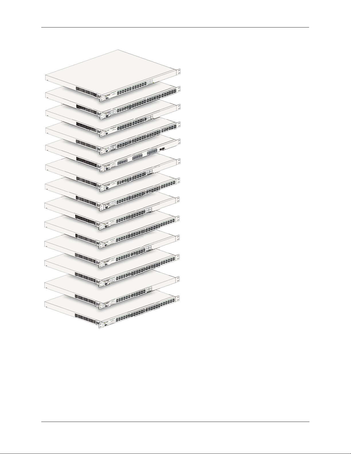
1 OmniSwitch 6850 Series
The OmniSwitch 6850 Series is an advanced fixed configuration family of Ethernet switches. These
switches provide wire rate layer-2 forwarding and layer-3 routing with advanced services.
OmniSwitch 6850-24L
22 23 24
1
24
23
UCT
19 20 2
OD
PR
22
R
E
AS
L
1
21
S
AS
12 13 14 15 16 17 18
8 9 10 11
5 6 7
1 2 3 4
BPS
PWR
PRI
OK
L
USB
OmniSwitch 6850-24
Console
PRI
OK
USB
OmniSwitch 6850-48L
2
1
CLASS 1 LASER PR
Console
PRI
OK
L
USB
OmniSwitch 6850-P24
Console
PRI
OK
L
USB
OmniSwitch 6850-P48
2
1
CLASS 1 LASER PR
Console
PRI
OK
X
USB
OmniSwitch 6850-U24
25
25
CLASS 1 LASER PR
26
Console
12 13 14
8 9 10 11
5 6 7
1 2 3 4
BPS
PWR
4
3
ODUCT
12 13 14 15 16 17 18
8 9 10 11
5 6 7
1 2 3 4
BPS
PWR
12 13 1
8 9 10 11
5 6 7
1 2 3 4
BPS
PWR
4
3
ODUCT
8
5 6 7
5 7
1 2 3 4
1 3
BPS
PWR
6 8
26
2 4
ODUCT
CL
29 30 31 32
26 27 28
23 24 25
19 20 21 22
15 16 17 18
24
23
19 20 21 22 23 24
ODUCT
22
21
CLASS 1 LASER PR
29 30 31 32
25 26 27 28
23 24
19 20 21 22
4 15 16 17 18
21 22 23
21 25
17 18 19 20
17 19
16
22 24
13 14 15
18 20
13 15
9 10 11 12
9 11
14 16
10 12
47 48
43 44 45 46
9 40 41 42
37 38 3
33 34 35 36
OmniSwitch 6850-48L
OmniSwitch 6850-P24L
46 47 48
43 44 45
39 40 41 42
37 38
33 34 35 36
OmniSwitch 6850-P48L
OmniSwitch 6850-U24X
24
24
ODUCT
23
CLASS 1 LASER PR
OmniSwitch 6850-24
BPS
PWR
PRI
OK
USB
OmniSwitch 6850-24
Console
BPS
PWR
PRI
OK
USB
OmniSwitch 6850-48
4
3
ODUCT
2
1
CLASS 1 LASER PR
Console
BPS
PWR
PRI
OK
X
26
USB
OmniSwitch 6850-24
25
ODUCT
25
CLASS 1 LASER PR
26
Console
BPS
PWR
PRI
OK
X
50
USB
OmniSwitch 6850-48
49
ODUCT
49
CLASS 1 LASER PR
50
Console
BPS
PWR
PRI
OK
USB
OmniSwitch 6850-P24
Console
BPS
PWR
PRI
OK
USB
OmniSwitch 6850-P48
4
3
ODUCT
2
1
CLASS 1 LASER PR
Console
BPS
PWR
PRI
OK
X
26
USB
OmniSwitch 6850-P24
25
ODUCT
25
CLASS 1 LASER PR
26
Console
BPS
PWR
PRI
OK
50
USB
OmniSwitch 6850-P48X
49
ODUCT
49
CLASS 1 LASER PR
50
Console
4 15 16 17 18
12 13 1
8 9 10 11
5 6 7
1 2 3 4
15 16 17 18 19 20 21
4 5 6 7 8 9 10 11 12 13 14
1 2 3
15 16 17 18
12 13 14
8 9 10 11
5 6 7
1 2 3 4
15 16 17 18 19 20 21
12 13 14
8 9 10 11
4 5 6 7
1 2 3
15 16 17 18
12 13 14
8 9 10 11
5 6 7
1 2 3 4
15 16 17 18 19 20 21
12 13 14
8 9 10 11
4 5 6 7
1 2 3
15 16 17 18
12 13 14
8 9 10 11
5 6 7
1 2 3 4
29 30 31 32
25 26 27 28
23 24
19 20 21 22
22 23 24
24
23
ODUCT
22
21
CLASS 1 LASER PR
29 30 31 32
26 27 28
23 24 25
19 20 21 22
22 23 24
24
23
ODUCT
22
21
CLASS 1 LASER PR
29 30 31 32
26 27 28
23 24 25
19 20 21 22
22 23 24
24
23
ODUCT
22
21
CLASS 1 LASER PR
29 30 31 32
26 27 28
23 24 25
19 20 21 22
46 47 48
43 44 45
39 40 41 42
37 38
33 34 35 36
OmniSwitch 6850-48
OmniSwitch 6850-24X
47 48
43 44 45 46
9 40 41 42
37 38 3
33 34 35 36
OmniSwitch 6850-48X
OmniSwitch 6850-P24
46 47 48
43 44 45
39 40 41 42
37 38
33 34 35 36
OmniSwitch 6850-P48
OmniSwitch 6850-P24X
47 48
43 44 45 46
9 40 41 42
37 38 3
33 34 35 36
OmniSwitch 6850-P48X
OmniSwitch 6850 Series Hardware Users Guide August 2007 page 1-1
Page 18

OmniSwitch 6850 Series
• The OmniSwitch 6850-24L (OS6850-24L) is a 24-port, 10/100 fixed stackable chassis with four
combo fiber SFP connectors.
• The OmniSwitch 6850-48L (OS6850-48L) is a 48-port, 10/100 fixed stackable chassis with four
combo fiber SFP connectors.
• The OmniSwitch 6850-P24L (OS6850-P24L) is a 24-port, 10/100 PoE fixed stackable chassis with
four combo fiber SFP connectors.
• The OmniSwitch 6850-P48L (OS6850-P48L) is a 48-port, 10/100 PoE fixed stackable chassis with
four combo fiber SFP connectors.
• The OmniSwitch 6850-U24X (OS6850-U24X) is a 24-port, 1000Base-X SFP fixed stackable chassis
with two 10/100/1000 Base-T combo ports. This switch also includes two 10-Gigabit XFP connectors.
• The OmniSwitch 6850-24 (OS6850-24) is a 24-port, 10/100/1000 fixed stackable chassis with four
combo fiber SFP connectors.
• The OmniSwitch 6850-48 (OS6850-48) is a 48-port, 10/100/1000 fixed stackable chassis with four
combo fiber SFP connectors.
• The OmniSwitch 6850-24X (OS6850-24X) is a 24-port, 10/100/1000 fixed stackable chassis with four
combo fiber SFP connectors.This switch also includes two 10-Gigabit XFP connectors.
• The OmniSwitch 6850-48X (OS6850-48X) is a 48-port, 10/100/1000 fixed stackable chassis. This
switch also includes two 10-Gigabit XFP connectors.
• The OmniSwitch 6850-P24 (OS6850-P24) is a 24-port, 10/100/1000 PoE fixed stackable chassis with
four combo fiber SFP connectors.
• The OmniSwitch 6850-P48 (OS6850-P48) is a 48-port, 10/100/1000 PoE fixed stackable chassis with
four combo fiber SFP connectors.
• The OmniSwitch 6850-P24X (OS6850-P24X) is a 24-port, 10/100/1000 PoE fixed stackable chassis
with four combo fiber SFP connectors. This switch also includes two 10-Gigabit XFP connectors.
• The OmniSwitch 6850-P48X (OS6850-P48X) is a 48-port, 10/100/1000 PoE fixed stackable chassis.
This switch also includes two 10-Gigabit XFP connectors.
The OmniSwitch 6850 Series switches offer effective availability, resiliency, and security features and are
ideal for the following network applications:
• Enterprise workgroups/LAN wiring closets
• Edge deployments and branch offices
• L3 aggregation/distribution layer switches in three-tier networks
• Small enterprise core switching
• Quality of service (QoS) for mission critical applications
• Data center server clusters
page 1-2 OmniSwitch 6850 Series Hardware Users Guide August 2007
Page 19

OmniSwitch 6850 Series Availability Features
Availability Features
The switch provides a broad variety of availability features. Availability features are hardware and
software-based safeguards that help to prevent the loss of data flow in the unlikely event of a subsystem
failure. In addition, some availability features allow users to maintain or replace hardware components
without powering off the switch or interrupting switch operations. Combined, these features provide added
resiliency and help to ensure that the switch or virtual chassis is consistently available for day-to-day
network operations.
Hardware-related availability features include:
• Software Rollback
• Backup Power Supplies
• Hot Swapping
• Hardware Monitoring
Software Rollback
Software rollback (also referred to as image rollback) essentially allows the OmniSwitch 6850 Series
switches to return to a prior “last known good” version of software in the event of a system software problem. The switch controls software rollback through its resilient directory structure design (i.e., /flash/
working and /flash/certified).
For detailed information on the software rollback feature, as well as the switch’s /flash/working and
/flash/certified directories, refer to the “Managing CMM Directory Content” chapter in the OmniSwitch
6800/6850/9000 Series Switch Management Guide.
Backup Power Supplies
The OmniSwitch 6850 Series switches support an optional backup power supply. This power supply is
connected to the rear of the unit. There is a power shelf provided with the unit that slides into the rear of
the chassis and is used to hold the power supplies. It can hold 510W or 360W power supply or in case of
non-PoE product switches 120W or 126W power supply. This provides redundant chassis power on a 1:1
basis.
Backup power supplies operate in active standby mode. If the primary power supply fails unexpectedly,
the backup power supply automatically takes up the full power load without disrupting the switch.
Note. For more information on backup power supplies, refer to Chapter 2, “OmniSwitch 6850 Series
Chassis and Hardware Components.”
OmniSwitch 6850 Series Hardware Users Guide August 2007 page 1-3
Page 20

Availability Features OmniSwitch 6850 Series
Hot Swapping
Hot swapping refers to the action of adding, removing, or replacing components without powering off
switches or disrupting other components.This feature facilitates hardware upgrades and maintenance and
allows users to easily replace components in the unlikely event of hardware failure.
The following hardware components can be hot swapped:
• Backup power supply
• Backup power supply connector cables
• SFPs
For instructions on hot swapping backup power supplies, refer to Chapter 2, “OmniSwitch 6850 Series
Chassis and Hardware Components.” For instructions on hot swapping combo connector SFPs, refer to the
instruction card provided with the SFP product.
Hardware Monitoring
Automatic Monitoring
Automatic monitoring refers to the switch’s built-in sensors that automatically monitor operations. If an
error is detected (e.g., over-threshold temperature), the switch immediately sends a trap to the user. The
trap is displayed on the console in the form of a text error message. (In the case of an over-threshold
temperature condition, the chassis displays an amber TMP LED in addition to sending a trap.)
LEDs
LEDs, which provide visual status information, are provided on the chassis front panel. LEDs are used to
indicate conditions such as hardware and software status, temperature errors, link integrity, data flow, etc.
For detailed LED descriptions, refer to Chapter 2, “OmniSwitch 6850 Series Chassis and Hardware
Components.”
User-Driven Monitoring
User-driven hardware monitoring refers to CLI commands that are entered by the user in order to access
the current status of hardware components. The user enters “show” commands that output information to
the console. Monitoring information for chassis components, such as the optional back up power supply,
chassis temperature sensor, and chassis fans is provided in Chapter 2, “OmniSwitch 6850 Series Chassis
and Hardware Components.” The show commands for all the features are described in detail in the
OmniSwitch CLI Reference Guide.
page 1-4 OmniSwitch 6850 Series Hardware Users Guide August 2007
Page 21
OmniSwitch 6850 Series OmniSwitch 6850 Series Application Examples
OmniSwitch 6850 Series Application Examples
The following OmniSwitch 6850 Series applications are described below:
• Gigabit-to-the-desktop migration
• Server aggregation
• Layer 3 Aggregation/Distribution
• Small Enterprise core
Gigabit-to-the-Desktop Migration
The OmniSwitch 6850 Series switches provide a migration path to Gigabit on the edge of the LAN.
For example:
10/100/1000 Layer 2+ Switching
10/100/1000 Layer 3 Switching
OmniSwitch 6850
Layer 2+ 10/100 Switching
Core Layer
OmniSwitch 8800
OmniSwitch 6850
OmniSwitch 6850
OmniSwitch 8800
Application Example: Gigabit-to-the-Desktop Migration
OmniSwitch 6850 Series Hardware Users Guide August 2007 page 1-5
Page 22
OmniSwitch 6850 Series Application Examples OmniSwitch 6850 Series
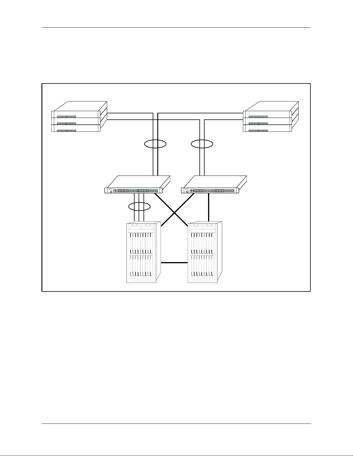
Server Aggregation
The OmniSwitch 6850 Series switch is a well-suited server aggregation switch, especially for
space-constrained data centers, where the switch can be installed in the same rack as the servers. For
example:
10/100/1000 Switching
10/100/1000 Switching
OmniSwitch 6850
Servers
Application Example: Server Aggregation
page 1-6 OmniSwitch 6850 Series Hardware Users Guide August 2007
Page 23
OmniSwitch 6850 Series OmniSwitch 6850 Series Application Examples
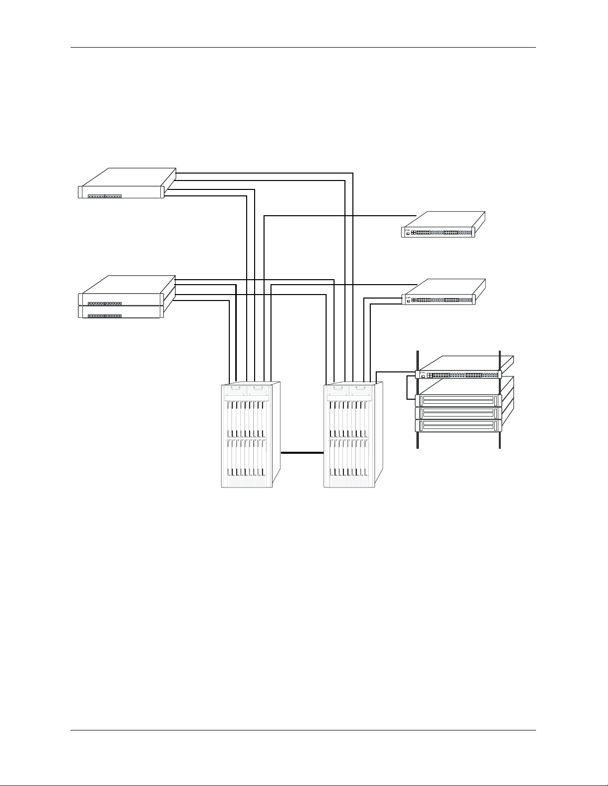
Layer 3 Aggregation/Distribution
The OmniSwitch 6850 Series switches placed in the distribution layer of three-tier networks provide highcapacity, wire speed Layer 2 switching, Layer 3 routing, and intelligent services near the edge of the
network. For example:
10/100 Switching
Gigabit
Uplinks
Aggregation Layer
(L2/L3 Switching)
OmniSwitch 6850
Multiple
1 Gig
10 Gig
10 Gig
OmniSwitch 6850
10 Gig
Core Layer
(L3)
Application Example: Layer 3 Aggregation/Distribution
OmniSwitch 6850 Series Hardware Users Guide August 2007 page 1-7
Page 24

OmniSwitch 6850 Series Application Examples OmniSwitch 6850 Series
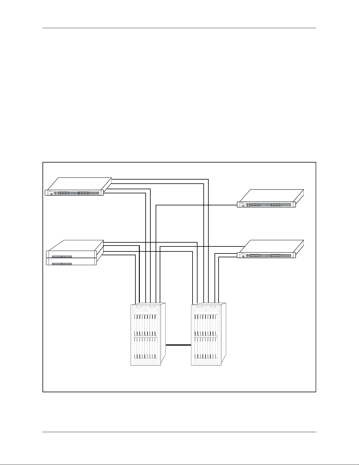
Small Enterprise Core
With its high-speed switching capacity, supported Layer 3 routing protocols, advanced network services,
and wire speed 10 Gigabit capability, the OmniSwitch 6850 Series provides effective core switching for
smaller Enterprise networks (200-500 ports). For example:
10/100 layer 2 Switching
10/100 layer 2 Switching
OmniSwitch 6850
Series Switch
Gigabit Layer 3 Switching
Gigabit Uplinks
OmniSwitch 6850
Series Switch
Internet
Router
10/100 layer 2 Switching
Servers
Internet
Application Example: Small Enterprise Core
page 1-8 OmniSwitch 6850 Series Hardware Users Guide August 2007
Page 25

2 OmniSwitch 6850 Series
Chassis and Hardware
Components
OmniSwitch 6850 Series switches are available in thirteen stackable chassis configurations as shown in
the table below:
• OmniSwitch 6850-24L
(OS6850-24L)
• OmniSwitch 6850-48L
(OS6850-48L)
• OmniSwitch 6850-P24L
(OS6850-P24L)
• OmniSwitch 6850-P48L
(OS6850-P48L)
• OmniSwitch 6850-U24X
(OS6850-U24X)
• OmniSwitch 6850-24
(OS6850-24)
• OmniSwitch 6850-48
(OS6850-48)
• OmniSwitch 6850-24X
(OS6850-24X)
• OmniSwitch 6850-48X
(OS6850-48X)
• OmniSwitch 6850-P24
(OS6850-P24)
24-port 10/100
48-port 10/100
24-port 10/100 Power over Ethernet (PoE)
48-port 10/100 Power over Ethernet (PoE)
24-port Gigabit SFP with 10 Gigabit uplinks
24-port 10/100/1000
48-port 10/100/1000
24-port with 10 Gigabit uplinks
48-port with 10 Gigabit uplinks
24-port 10/100/1000 Power over Ethernet (PoE)
• OmniSwitch 6850-P48
(OS6850-P48)
• OmniSwitch 6850-P24X
(OS6850-P24X)
• OmniSwitch 6850-P48X
(OS6850-P48X)
OmniSwitch 6850 Series Hardware Users Guide August 2007 page 2-1
48-port 10/100/1000 Power over Ethernet (PoE)
24-port PoE with 10 Gigabit uplinks
48-port PoE with 10 Gigabit uplinks
Page 26

OmniSwitch 6850 Series Chassis and Hardware Components
This chapter includes detailed information on these chassis types. Topics include:
• OmniSwitch 6850 Series chassis descriptions
• Technical specifications
• Switch mounting
• Booting OmniSwitch 6850 Series switches
• Power cords, console port, and pinout specifications
• OmniSwitch 6850 Series power supplies
• Monitoring the chassis
page 2-2 OmniSwitch 6850 Series Hardware Users Guide August 2007
Page 27
OmniSwitch 6850 Series Chassis and Hardware Components
4
2
3
2
22
21
0
24
2
T
23
19
UC
OD
8
2
1
2
R PR
SE
A
L
17
21
SS 1
A
L
C
16
15
14
13
2
1
1
1
10
9
8
7
6
5
4
3
2
1
S
BP
WR
P
RI
P
K
O
L
USB
OmniSwitch 6850-24
sole
n
Co
4
3
2
1
PS
B
R
PW
I
R
P
OK
USB
OmniSwitch 6850-48L
4
T
3
C
U
OD
PR
2
R
SE
A
L
1
CLASS 1
e
onsol
C
4
1 2 3
PS
B
PWR
PRI
OK
L
B
S
U
OmniSwitch 6850-P24
onsole
C
1 2 3 4
BPS
PWR
PRI
OK
L
USB
OmniSwitch 6850-P48
4
T
3
C
U
OD
PR
2
SER
A
1 L
1
CLASS
Console
1 2 3
1 3
BPS
PWR
PRI
OK
X
26
2 4
USB
OmniSwitch 6850-U24
25
ODUCT
R
P
ER
S
A
L
25
SS 1
CLA
26
Console
BPS
PWR
PRI
OK
USB
OmniSwitch 6850-24
Console
5 6 7
1 2 3 4
BPS
PWR
PRI
OK
USB
OmniSwitch 6850-48
4
3
ODUCT
2
1
CLASS 1 LASER PR
Console
1 2 3 4 5 6 7
BPS
PWR
PRI
OK
X
26
USB
OmniSwitch 6850-24
25
ODUCT
25
CLASS 1 LASER PR
26
Console
5 6 7
1 2 3 4
BPS
PWR
PRI
OK
X
50
USB
OmniSwitch 6850-48
49
ODUCT
49
CLASS 1 LASER PR
50
Console
4 5 6 7
1 2 3
BPS
PWR
PRI
OK
USB
OmniSwitch 6850-P24
Console
5 6 7
1 2 3 4
BPS
PWR
PRI
OK
USB
OmniSwitch 6850-P48
4
3
ODUCT
PR
2
1
CLASS 1 LASER
Console
4 5 6 7
1 2 3
BPS
PWR
PRI
OK
X
26
USB
OmniSwitch 6850-P24
25
ODUCT
25
CLASS 1 LASER PR
26
Console
5 6 7
1 2 3 4
BPS
PWR
PRI
OK
50
USB
OmniSwitch 6850-P48X
49
49
CLASS 1 LASER PRODUCT
50
Console
5
5 6 7
5
4
6
6 7
5 6 7
5 7
6 8
7
8 9 10 11 12 13 14
8 9 10 11
8 9 10 11
8 9 10 11
8 9 10 11
8 9 10 11
9
8
8 9 10 11
8 9
8
8 9 10 11
14
3
1
2
1
1
0 1
1
12 13 14 15 16 17 18 19 20 21 22
1
12 13
11
10
9 10 11 12
4 15 16 17 18
12 13 1
15 16 17
15 16 17 18
12 13 14
15 16 17 18 19 20 21
12 13 14
15 16 17 18
12 13 14
15 16 17
12 13 14
15 16 17 18
12 13 14
19
8
1
7
1
16
15
19
4 15 16 17 18
13 14 15
13 15
11
9
14 16
10 12
19 20 21 22
18 19 20 21
19 20 21 22
19 20 21 22
18 19 20 21
19 20 21 22
3
3
32
31
30
9
2
8
2
27
26
5
2
24
23
2
2
21
20
23 24
24
T
23
UC
D
O
22
R PR
E
AS
1 L
21
SS
A
L
C
33
31 32
30
29
25 26 27 28
23 24
21 22
20
24
21 22 23
21 25
17 18 19 20
17 19
16
22 24
18 20
33 34 35 36
29 30 31 32
25 26 27 28
23 24
22 23 24
24
23
ODUCT
22
21
CLASS 1 LASER PR
33 34 35 36
29 30 31 32
26 27 28
23 24 25
22 23 24
24
23
ODUCT
22
21
CLASS 1 LASER PR
33 34 35 36
26 27 28 29 30 31 32
23 24 25
22 23 24
24
23
ODUCT
22
21
CLASS 1 LASER PR
33 34 35 36
29 30 31 32
26 27 28
23 24 25
48
47
6
4
5
4
44
3
4
40 41 42
9
3
38
37
6
3
5
3
34
48
46 47
45
43 44
41 42
40
39
8
3
37
36
34 35
24
UCT
D
O
R
P
R
23
LASE
1
S
S
CLA
46 47 48
43 44 45
39 40 41 42
37 38
47 48
43 44 45 46
9 40 41 42
37 38 3
46 47 48
43 44 45
39 40 41 42
37 38
47 48
43 44 45 46
9 40 41 42
37 38 3
OmniSwitch 6850-24L
OmniSwitch 6850-48L
OmniSwitch 6850-P24L
OmniSwitch 6850-P48L
OmniSwitch 6850-U24X
OmniSwitch 6850-24
OmniSwitch 6850-48
OmniSwitch 6850-24X
OmniSwitch 6850-48X
OmniSwitch 6850-P24
OmniSwitch 6850-P48
OmniSwitch 6850-P24X
OmniSwitch 6850-P48X
OmniSwitch 6850 Series Hardware Users Guide August 2007 page 2-3
Page 28

OmniSwitch 6850-24L OmniSwitch 6850 Series Chassis and Hardware Components
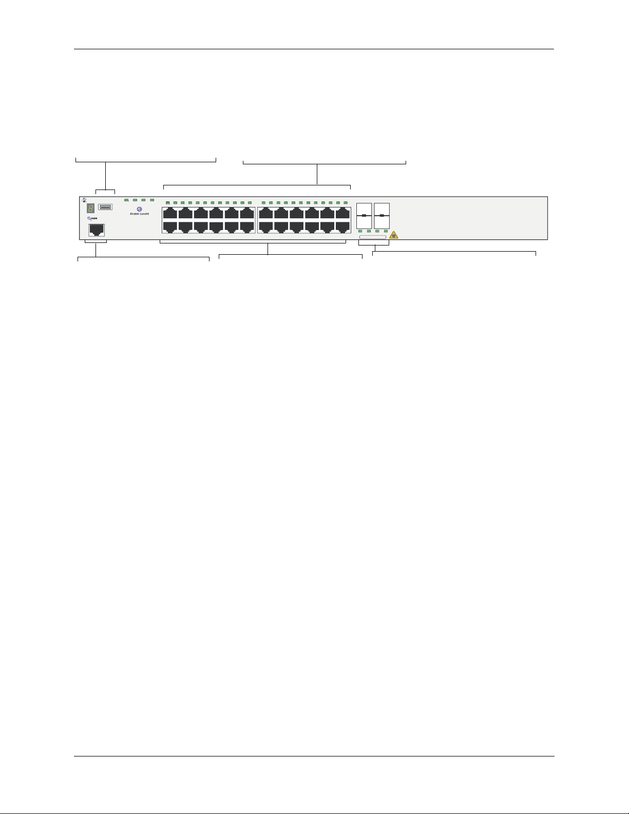
OmniSwitch 6850-24L
The OmniSwitch 6850-24L is a stackable edge/workgroup switch offering 20 unshared 10/100Base-T, as
well as four combo individually configurable to be 10/100/1000Base-T or 1000Base-X
high-speed connections.
The front panel of the OS6850-24L chassis contains the following major components:
• System status and slot indicator LEDs
• (20) unshared 10/100Base-T
• (4) shared combo 10/100/1000Base-T
• (4) Combo SFP connectors for 1000Base-X connections
• Console port (RJ-45)
• USB port (USB 2.0)
Note. USB 2.0 is not supported in this release.
Note. The 20 (non-combo) 10/100Base-T on the OmniSwitch 6850-24L can be upgraded to
10/100/1000Base-T. Please contact your Alcatel-Lucent representative for more information.
page 2-4 OmniSwitch 6850 Series Hardware Users Guide August 2007
Page 29
OmniSwitch 6850 Series Chassis and Hardware Components OmniSwitch 6850-24L
Refer to the illustration below for more front panel information. For detailed LED descriptions, refer to
page 2-54. For information on the chassis rear panel, refer to page 2-56.
Status and Slot Indicator LEDs
USB Port
High speed USB 2.0 port, which
can be used for quick upgrades.
PRI PWR BPS
OmniSwitch 6850-24L
Console
OK
USB
1 2 3 4 5 6 7 8 9 10 11 12 13 14 15 16 17 18 19 20 21 22 23 24
For information on the OS6850-24L’s
status and slot indicator LEDs, refer to
page 2-54.
21 22 23 24
CLASS 1 LASER PRODUCT
Console Port
The OS6850-24L front panel
provides one RJ-45 port for console connections. Console connections are used by network
administrators for switch management. This female RJ-45 connector provides a DTE console
connection.
10/100 Mbps and 10/100/1000Mbps
The OS6850-24L provides 20 fixed
10/100BaseT non-combo (1–20) and 4
fixed
10/100/1000BaseT combo 21–24).
These are auto-sensing and auto-MDIX
and use RJ-45 connectors.
OmniSwitch 6850-24L Front Panel
Combo SFP
The OS6850-24L provides four combo
SFP connectors for 1000Base-X highspeed connections.
By default, when an SFP is installed in a
combo port, it takes over the port number
of the corresponding RJ-45 Ethernet port.
In other words, if an SFP is installed in
the slot labeled 24, Ethernet port 24
would no longer be available and cannot
be used for 10/100/1000 traffic. This
default setting is referred to as “preferred
fiber.” Refer to “Configuring Ethernet” in
Network Configuration Guide for
the
detailed information, including
steps for
configuring combo port settings.
OmniSwitch 6850 Series Hardware Users Guide August 2007 page 2-5
Page 30

OmniSwitch 6850-24L OmniSwitch 6850 Series Chassis and Hardware Components
OS6850-24L Specifications
Total unshared
20
10/100Base-T per switch (1–20)
Total shared 10/100/1000Base-T
4
combo per switch
(21–24)
Total combo 1000Base-X
4
combo SFP connectors per
switch (21–24)
Total 10/100Base-T per stack 160 (stack of eight switches)
Total combo SFP connectors per
32 (stack of eight switches)
stack
Power 126/120W (AC/DC) power supply
Flash memory size 64 MB
RAM memory size 256 MB SDRAM
Overall Width (rack-mount
19 inches, approx.
flanges included)
Chassis Width (rack-mount
17.5 inches
flanges not included)
Height 1.73 inches
Height (rack units) 1 RU
Chassis Depth 10.5 inches without power supplies installed;
16.75 inches with power supplies installed
Weight 14 lbs (6.24 Kg), approx.
Humidity 5% to 90% Relative Humidity (Operating)
0% to 95% Relative Humidity (Storage)
Operating Temperature 0 to 45 degrees, Celsius
Storage Temperature -20 to 70 degrees, Celsius
Altitude Operating altitude: sea level at 40 degrees, Celsius and
10000 feet at 0 degrees, Celsius
Storage altitude: sea level to 40000 feet
Standards supported 802.3z, 802.3ab, 1000Base-T, IEEE 802.3u
Data rate (RJ-45) 10 or 100 Mbps (full or half duplex)
1 Gigabit per second (full duplex)
Data rate (SFP) 1 Gigabit per second (full duplex)
Maximum frame size 9216 bytes
Connections supported 10/100/1000Base-T and 1000Base-X
Cable supported
(RJ-45)
10BaseT: unshielded twisted-pair (UTP)
100BaseTX: unshielded twisted-pair (UTP), Category 5, EIA/TIA 568
or shielded twisted-pair (STP), Category 5, 100 ohm
1000BaseT: unshielded twisted-pair (UTP), Category 5e
page 2-6 OmniSwitch 6850 Series Hardware Users Guide August 2007
Page 31

OmniSwitch 6850 Series Chassis and Hardware Components OmniSwitch 6850-24L
OS6850-24L Specifications
Maximum cable distance
(RJ-45)
100 meters
OmniSwitch 6850 Series Hardware Users Guide August 2007 page 2-7
Page 32

OmniSwitch 6850-48L OmniSwitch 6850 Series Chassis and Hardware Components
OmniSwitch 6850-48L
The OmniSwitch 6850-48L is a stackable edge/workgroup switch offering 44 unshared 10/100Base-T, as
well as four combo individually configurable to 10/100/1000Base-T or 1000Base-X high speed connections.
The front panel of the OS6850-48L chassis contains the following major components:
• System status and slot indicator LEDs
• (44) unshared 10/100Base-T
• (4) shared combo 10/100/1000Base-T
• (4) Combo SFP connectors for 1000Base-X connections
• Console port (RJ-45)
• USB port (USB 2.0)
Note. USB 2.0 is not supported in this release.
Note. The 44 (non-combo) 10/100Base-T on the OmniSwitch 6850-48L can be upgraded to
10/100/1000Base-T. Please contact your Alcatel-Lucent representative for more information.
page 2-8 OmniSwitch 6850 Series Hardware Users Guide August 2007
Page 33

OmniSwitch 6850 Series Chassis and Hardware Components OmniSwitch 6850-48L
Refer to the illustration below for more front panel information. For detailed LED descriptions, refer to
page 2-54. For information on the chassis rear panel, refer to page 2-56.
Status and Slot Indicator LEDs
For detailed information on OS6850-48L
status and slot indicator LEDs, refer to page
2-54.
USB Port
High speed (480 Mbps) USB 2.0
port, which can be used for quick
upgrades.
OmniSwitch 6850-48L
Console
USB
OK
1 2 3 4
CLASS 1 LASER PRODUCT
1 2 3 4 5 6 7 8 9 10 11 12 13 14 15 16 17 18 19 20 21 22 23 24 25 26 27 28 29 30 31 32 33 34 35 36 37 38 39 40 41 42 43 44 45 46 47 48
PRI PWR BPS
Console Port
The OS6850-48L front panel provides one
RJ-45 port for console connections. Console connections are used by network
administrators for switch management.
This female RJ-45 connector provides a
DTE console connection.
10/100Mbps and 10/100/1000 Mbps
The OS6850-48L provides 44 fixed
10/100BaseT (5–48) and 4 fixed 10/100/1000BaseT
combo (1–4). These are auto-sensing and auto-MDIX and
use RJ-45 connectors.
Combo SFP
The OS6850-48L provides four combo SFP connectors for 1000Base-X highspeed connections
.
By default, when an SFP is installed in a combo port, it takes over the port number of the corresponding RJ-45 Ethernet port. In other words, if an SFP is
installed in the slot labeled 4, Ethernet port 4 would no longer be available and
cannot be used for 10/100/1000 traffic. This default setting is referred to as
“preferred fiber.” Refer to “Configuring Ethernet” in the
Network Configuration Guide for detailed information, including steps for configuring combo port settings.
OmniSwitch 6850-48L Front Panel
OmniSwitch 6850 Series Hardware Users Guide August 2007 page 2-9
Page 34

OmniSwitch 6850-48L OmniSwitch 6850 Series Chassis and Hardware Components
OS6850-48L Specifications
Total unshared 10/100Base-T
44
per switch (5–48)
Total shared 10/100/1000Base-T
4
combo per switch (1–4)
Total combo SFP connectors per
4
switch
Total 10/100Base-T per stack 352 (stack of eight switches)
Total combo SFP connectors per
32 (stack of eight switches)
stack
Power 126/120W (AC/DC) power supply
Flash memory size 64 MB
RAM memory size 256 MB SDRAM
Overall Width (rack-mount
19 inches, approx.
flanges included)
Chassis Width (rack-mount
17.5 inches
flanges not included)
Height 1.73 inches
Height (rack units) 1 RU
Chassis Depth 10.5 inches without power supplies installed;
16.75 inches with power supplies installed
Weight 14 lbs (6.24 Kg), approx.
Humidity 5% to 90% Relative Humidity (Operating)
0% to 95% Relative Humidity (Storage)
Operating Temperature 0 to 45 degrees, Celsius
Storage Temperature -20 to 70 degrees, Celsius
Altitude Operating altitude: sea level at 40 degrees, Celsius and
10000 feet at 0 degrees, Celsius
Storage altitude: sea level to 40000 feet
Standards supported 802.3z, 802.3ab, 1000Base-T, IEEE 802.3u
Data rate (RJ-45) 10 or 100 Mbps (full or half duplex)
1 Gigabit per second (full duplex)
Data rate (SFP) 1 Gigabit per second (full duplex)
Maximum frame size 9216
Connections supported 10/100/1000Base-T and 1000Base-X
Cable supported
(RJ-45)
10BaseT: unshielded twisted-pair (UTP)
100BaseTX: unshielded twisted-pair (UTP), Category 5, EIA/TIA 568
or shielded twisted-pair (STP), Category 5, 100 ohm
1000BaseT: unshielded twisted-pair (UTP), Category 5e
Maximum cable distance
100 meters
(RJ-45)
page 2-10 OmniSwitch 6850 Series Hardware Users Guide August 2007
Page 35

OmniSwitch 6850 Series Chassis and Hardware Components OmniSwitch 6850-P24L
OmniSwitch 6850-P24L
The OmniSwitch 6850-P24L is a stackable edge/workgroup switch offering 20 unshared 10/100Base-T
Power over Ethernet (PoE), as well as four combo individually configurable to be
10/100/1000Base-T PoE or 1000Base-X high speed connections.
The front panel of the OS6850-P24L chassis contains the following major components:
• System status and slot indicator LEDs
• (20) unshared 10/100Base-T PoE
• (4) shared combo 10/100/1000Base-T PoE
• (4) Combo SFP connectors for 1000Base-X connections
• Console port (RJ-45)
• USB port (USB 2.0)
Note. USB 2.0 is not supported in this release.
Note. The 20 (non-combo) 10/100Base-T PoE on the OmniSwitch 6850-P24L can be upgraded to 10/100/
1000Base-T PoE. Please contact your Alcatel-Lucent representative for more information.
OmniSwitch 6850 Series Hardware Users Guide August 2007 page 2-11
Page 36

OmniSwitch 6850-P24L OmniSwitch 6850 Series Chassis and Hardware Components
Refer to the illustration below for more front panel information. For detailed LED descriptions, refer to
page 2-54. For information on the chassis rear panel, refer to page 2-56.
USB Port
High speed USB 2.0 port, which
can be used for quick upgrades.
OmniSwitch 6850-P24L
Console
OK PRI PWR BPS
USB
1 2 3 4 5 6 7 8 9 10 11 12 13 14 15 16 17 18 19 20 21 22 23 24
Console Port
The OS6850-P24L front panel
provides one RJ-45 port for console connections. Console connections are used by network
administrators for switch management. This female RJ-45 connector provides a DTE console
connection.
Status and Slot Indicator LEDs
For information on the OS6850-P24L’s
status and slot indicator LEDs, refer to
page 2-54.
21 22 23 24
CLASS 1 LASER PRODUCT
10/100 Mbps and 10/100/1000Mbps PoE
The OS6850-P24L provides 20 fixed
10/100BaseT non-combo PoE (1–20) and 4
fixed
10/100/1000BaseT combo PoE (21–24).
These are auto-sensing and auto-MDIX
and use RJ-45 connectors.
Combo SFP
The OS6850-P24L provides four combo
SFP connectors for 1000Base-X highspeed connections.
By default, when an SFP is installed in a
combo port, it takes over the port number
of the corresponding RJ-45 Ethernet port.
In other words, if an SFP is installed in
the slot labeled 24, Ethernet port 24
would no longer be available and cannot
be used for 10/100/1000 traffic. This
default setting is referred to as “preferred
fiber.” Refer to “Configuring Ethernet” in
Network Configuration Guide for
the
detailed information, including
steps for
configuring combo port settings.
OmniSwitch 6850-P24L Front Panel
page 2-12 OmniSwitch 6850 Series Hardware Users Guide August 2007
Page 37

OmniSwitch 6850 Series Chassis and Hardware Components OmniSwitch 6850-P24L
OS6850-P24L Specifications
Total unshared 10/100Base-T
20
PoE per switch (1–20)
Total shared 10/100/1000Base-T
4
combo PoE per switch (21–24)
Total combo 1000Base-X
4
combo SFP connectors per
switch (21–24)
Total 10/100Base-T PoE per
160 (stack of eight switches)
stack
Total combo SFP connectors per
32 (stack of eight switches)
stack
Power 510/360W power supply
Flash memory size 64 MB
RAM memory size 256 MB SDRAM
Overall Width (rack-mount
19 inches, approx.
flanges included)
Chassis Width (rack-mount
17.5 inches
flanges not included)
Height 1.73 inches
Height (rack units) 1 RU
Chassis Depth 10.5 inches without power supplies installed;
16.75 inches with power supplies installed
Weight 14 lbs (6.24 Kg), approx.
Humidity 5% to 90% Relative Humidity (Operating)
0% to 95% Relative Humidity (Storage)
Operating Temperature 0 to 45 degrees, Celsius
Storage Temperature -20 to 70 degrees, Celsius
Altitude Operating altitude: sea level at 40 degrees, Celsius and
10000 feet at 0 degrees, Celsius
Storage altitude: sea level to 40000 feet
Standards supported 802.3z, 802.3ab, 1000Base-T, IEEE 802.3u, 802.3af (DTE Power via
MDI MIB); IAB RFCs 826, 894
Data rate (RJ-45) 10 or 100 Mbps (full or half duplex)
1 Gigabit per second (full duplex)
Data rate (SFP) 1 Gigabit per second (full duplex)
Maximum frame size 9216 bytes
Connections supported IP phones, Bluetooth Access Points, Internet cameras, and other
devices requiring power over Ethernet
OmniSwitch 6850 Series Hardware Users Guide August 2007 page 2-13
Page 38

OmniSwitch 6850-P24L OmniSwitch 6850 Series Chassis and Hardware Components
OS6850-P24L Specifications
Cable supported
(RJ-45)
10BaseT: unshielded twisted-pair (UTP)
100BaseTX: unshielded twisted-pair (UTP), Category 5, EIA/TIA 568
or shielded twisted-pair (STP), Category 5, 100 ohm
1000BaseT: unshielded twisted-pair (UTP), Category 5e
Power supplied to port 15.4 watts per port
Maximum cable distance
100 meters
(RJ-45)
page 2-14 OmniSwitch 6850 Series Hardware Users Guide August 2007
Page 39

OmniSwitch 6850 Series Chassis and Hardware Components OmniSwitch 6850-P48L
OmniSwitch 6850-P48L
The OmniSwitch 6850-P48L is a stackable edge/workgroup switch offering 44 unshared 10/100Base-T
Power over Ethernet (PoE), as well as four combo individually configurable to
10/100/1000Base-T PoE or 1000Base-X high speed connections.
The front panel of the OS6850-P48L chassis contains the following major components:
• System status and slot indicator LEDs
• (44) unshared 10/100Base-T PoE
• (4) shared combo 10/100/1000Base-T PoE
• (4) Combo SFP connectors for 1000Base-X connections
• Console port (RJ-45)
• USB port (USB 2.0)
Note. USB 2.0 is not supported in this release.
Note. The 44 (non-combo) 10/100Base-T PoE on the OmniSwitch 6850-P48L can be upgraded to 10/100/
1000Base-T PoE. Please contact your Alcatel-Lucent representative for more information.
OmniSwitch 6850 Series Hardware Users Guide August 2007 page 2-15
Page 40

OmniSwitch 6850-P48L OmniSwitch 6850 Series Chassis and Hardware Components
Refer to the illustration below for more front panel information. For detailed LED descriptions, refer to
page 2-54. For information on the chassis rear panel, refer to page 2-56.
Status and Slot Indicator LEDs
For detailed information on
OS6850-P48L’s status and slot indicator LEDs, refer to page 2-54.
USB Port
High speed (480 Mbps) USB 2.0
port, which can be used for quick
upgrades.
10/100Mbps and 10/100/1000 Mbps PoE
The OS6850-P48L provides 44 fixed 10/100BaseT
non-combo PoE (5–48) and 4 fixed
10/100/1000BaseT combo PoE (1–4). These are autosensing and auto-MDIX and use RJ-45 connectors.
OmniSwitch 6850-P48L
Console
USB
OK PRI PWR BPS
1 2 3 4
CLASS 1 LASER PRODUCT
1 2 3 4 5 6 7 8 9 10 11 12 13 14 15 16 17 18 19 20 21 22 23 24 25 26 27 28 29 30 31 32 33 34 35 36 37 38 39 40 41 42 43 44 45 46 47 48
Console Port
The OS6850-P48L front panel provides
one RJ-45 port for console connections.
Console connections are used by network
administrators for switch management.
This female RJ-45 connector provides a
DTE console connection.
Combo SFP
The OS6850-P48L provides four combo SFP connectors for 1000Base-X highspeed connections
.
By default, when an SFP is installed in a combo port, it takes over the port number of the corresponding RJ-45 Ethernet port. In other words, if an SFP is
installed in the slot labeled 4, Ethernet port 4 would no longer be available and
cannot be used for 10/100/1000 traffic. This default setting is referred to as
“preferred fiber.” Refer to “Configuring Ethernet” in the
Network Configuration Guide for detailed information, including steps for configuring combo port settings.
OmniSwitch 6850-P48L Front Panel
page 2-16 OmniSwitch 6850 Series Hardware Users Guide August 2007
Page 41

OmniSwitch 6850 Series Chassis and Hardware Components OmniSwitch 6850-P48L
OS6850-P48L Specifications
Total unshared 10/100Base-T
44
PoE per switch (5–48)
Total shared 10/100/1000Base-T
4
combo PoE per switch (1–4)
Total combo 1000Base-X
4
combo SFP connectors per
switch
Total 10/100Base-T PoE per
352 (stack of eight switches)
stack
Total combo SFP connectors per
32 (stack of eight switches)
stack
Power 510/360W power supply
Flash memory size 64 MB
RAM memory size 256 MB SDRAM
Overall Width (rack-mount
19 inches, approx.
flanges included)
Chassis Width (rack-mount
17.5 inches
flanges not included)
Height 1.73 inches
Height (rack units) 1 RU
Chassis Depth 10.5 inches without power supplies installed;
16.75 inches with power supplies installed
Weight 14 lbs (6.24 Kg), approx.
Humidity 5% to 90% Relative Humidity (Operating)
0% to 95% Relative Humidity (Storage)
Operating Temperature 0 to 45 degrees, Celsius
Storage Temperature -20 to 70 degrees, Celsius
Altitude Operating altitude: sea level at 40 degrees, Celsius and
10000 feet at 0 degrees, Celsius
Storage altitude: sea level to 40000 feet
Standards supported 802.3z, 802.3ab, 1000Base-T, IEEE 802.3u, 802.3af (DTE Power via
MDI MIB); IAB RFCs 826, 894
Data rate (RJ-45) 10 or 100 Mbps (full or half duplex)
1 Gigabit per second (full duplex)
Data rate (SFP) 1 Gigabit per second (full duplex)
Maximum frame size 9216
Connections supported IP phones, Bluetooth Access Points, Internet cameras, and other
devices requiring power over Ethernet
OmniSwitch 6850 Series Hardware Users Guide August 2007 page 2-17
Page 42

OmniSwitch 6850-P48L OmniSwitch 6850 Series Chassis and Hardware Components
OS6850-P48L Specifications
Cable supported
(RJ-45)
10BaseT: unshielded twisted-pair (UTP)
100BaseTX: unshielded twisted-pair (UTP), Category 5, EIA/TIA 568
or shielded twisted-pair (STP), Category 5, 100 ohm
1000BaseT: unshielded twisted-pair (UTP), Category 5e
Power supplied to port 15.4 watts per port
Maximum cable distance
100 meters
(RJ-45)
page 2-18 OmniSwitch 6850 Series Hardware Users Guide August 2007
Page 43

OmniSwitch 6850 Series Chassis and Hardware Components OmniSwitch 6850-U24X
OmniSwitch 6850-U24X
The OmniSwitch 6850-U24X is an edge/workgroup switch offering 24 1000Base-X SFP connectors, two
(2) 10 Gigabit XFP connectors, as well as four combo individually configurable to 10/100/1000Base-T.
The front panel of the OS6850-U24X chassis contains the following major components:
• System status and slot indicator LEDs
• (22) unshared 1000Base-X SFP connectors
• (2) shared combo 1000Base-X SFP connectors
• (2) Combo RJ-45 10/100/1000Base-T
• (2) 10 Gigabit XFP connectors
• Console port (RJ-45)
• USB port (USB 2.0)
Note. USB 2.0 is not supported in this release.
OmniSwitch 6850 Series Hardware Users Guide August 2007 page 2-19
Page 44

OmniSwitch 6850-U24X OmniSwitch 6850 Series Chassis and Hardware Components
Refer to the illustration below for more front panel information. For detailed LED descriptions, refer to
page 2-54. For information on the chassis rear panel, refer to page 2-56.
USB Port
High speed USB 2.0 port,
which can be used for quick
upgrades.
1000Mbps SFP
The OS6850-U24X provides 22 non-combo SFP connectors for 1000Base-X SFP connectors (1–22) and 2
combo SFP connectors for1000Base-X SFP connectors
(23–24).
PRI PWR BPS
OmniSwitch 6850-U24X
Console
OK
USB
25
25
26
CLASS 1 LASER PRODUCT
Console Port
The OS6850-U24X front panel
provides one RJ-45 port for console connections. Console connections are used by network
administrators for switch man-
1 2 3 4 5 6 7 8 9 10 11 12 13 14 15 16 17 18 19 20 21 22 23 24
1 3 5 7
26
2 4 6 8
XFP
The OS6850-U24X front panel
provides two for 10 Gbps Small
Form Factor Pluggable (XFP)
transceivers.
agement. This female RJ-45 connector provides a DTE console
connection.
Status and Slot Indicator LEDs
For information on the OS6850-U24X’s
status and slot indicator LEDs, refer to page
2-54.
9 11 13 15
10 12 14 16
17 19 21 23
18 20 22 24
23 24
CLASS 1 LASER PRODUCT
Combo RJ-45 10/100/1000
The OS6850-U24X provides two combo
10/100/1000BaseT
.
By default, when an SFP is installed in a
combo port, it takes over the port number
of the corresponding RJ-45 Ethernet port.
In other words, if an SFP is installed in the
slot labeled 24, Ethernet port 24 would no
longer be available and cannot be used for
10/100/1000 traffic. This default setting is
referred to as “preferred fiber.” Refer to
“Configuring Ethernet” in the Network
Configuration Guide for detailed information, including steps for configuring
combo port settings
.
OmniSwitch 6850-U24X Front Panel
page 2-20 OmniSwitch 6850 Series Hardware Users Guide August 2007
Page 45

OmniSwitch 6850 Series Chassis and Hardware Components OmniSwitch 6850-U24X
OS6850-U24X Specifications
Total unshared 1000Base-X SFP
22
connectors per switch (1–22)
Total shared 1000Base-X SFP
2
connectors per switch (23–24)
Total combo10/100/1000Base-T
2
per switch (23–24)
Total XFP Connectors (25–26) 2
Total 1000Base-X SFP connec-
192 (stack of eight switches)
tors per stack
Total combo 10/100/1000Base-
16 (stack of eight switches)
T per stack
Power 126/120W (AC/DC) power supply
Flash memory size 64 MB
RAM memory size 256 MB SDRAM
Overall Width (rack-mount
19 inches, approx.
flanges included)
Chassis Width (rack-mount
17.5 inches
flanges not included)
Height 1.73 inches
Height (rack units) 1 RU
Chassis Depth 10.5 inches without power supplies installed;
16.75 inches with power supplies installed
Weight 14 lbs (6.24 Kg), approx.
Humidity 5% to 90% Relative Humidity (Operating)
0% to 95% Relative Humidity (Storage)
Operating Temperature 0 to 45 degrees, Celsius
Storage Temperature -20 to 70 degrees, Celsius
Altitude Operating altitude: sea level at 40 degrees, Celsius and
10000 feet at 0 degrees, Celsius
Storage altitude: sea level to 40000 feet
Standards supported 10/100/1000Base-T and 1000Base-X
Data rate (RJ-45) 10 or 100 Mbps (full or half duplex)
1 Gigabit per second (full duplex)
Data rate (SFP) 100 and 1000 Mbps (full duplex)
Data rate (XFP) 10 Gigabits per second (full duplex)
Maximum frame size 9216 Bytes
Connections supported 10/100/1000base-T, 1000Base-X, 10GBASE-L
OmniSwitch 6850 Series Hardware Users Guide August 2007 page 2-21
Page 46

OmniSwitch 6850-U24X OmniSwitch 6850 Series Chassis and Hardware Components
OS6850-U24X Specifications
Cable supported
(RJ-45)
Maximum cable distance
(RJ-45)
10BaseT: unshielded twisted-pair (UTP)
100BaseTX: unshielded twisted-pair (UTP), Category 5, EIA/TIA 568
or shielded twisted-pair (STP), Category 5, 100 ohm
1000BaseT: unshielded twisted-pair (UTP), Category 5e
100 meters
page 2-22 OmniSwitch 6850 Series Hardware Users Guide August 2007
Page 47

OmniSwitch 6850 Series Chassis and Hardware Components OmniSwitch 6850-24
OmniSwitch 6850-24
The OmniSwitch 6850-24 is a stackable edge/workgroup switch offering 20 unshared 10/100/1000 BaseT, as well as four combo individually configurable to be 10/100/1000 Base-T or 1000 Base-X high speed
connections.
The front panel of the OS6850-24 chassis contains the following major components:
• System status and slot indicator LEDs
• (20) unshared 10/100/1000Base-T
• (4) shared combo 10/100/1000Base-T
• (4) Combo SFP connectors for 1000Base-X connections
• Console port (RJ-45)
• USB port (USB 2.0)
Note. USB 2.0 is not supported in this release.
OmniSwitch 6850 Series Hardware Users Guide August 2007 page 2-23
Page 48

OmniSwitch 6850-24 OmniSwitch 6850 Series Chassis and Hardware Components
Refer to the illustration below for more front panel information. For detailed LED descriptions, refer to
page 2-54. For information on the chassis rear panel, refer to page 2-56.
USB Port
High speed USB 2.0 port, which
can be used for quick upgrades.
OmniSwitch 6850-24
Console
OK
USB
1 2 3 4 5 6 7 8 9 10 11 12 13 14 15 16 17 18 19 20 21 22 23 24
PRI PWR BPS
Console Port
The OS6850-24 front panel provides one RJ-45 port for console
connections. Console connections are used by network administrators for switch management.
This female RJ-45 connector
provides a DTE console connection.
Status and Slot Indicator LEDs
For information on the OS6850-24’s
status and slot indicator LEDs, refer
to page 2-54.
10/100/1000Mbps
The OS6850-24 provides 20 fixed 0/
100/1000BaseT non-combo (1–20)
and 4 fixed
10/100/1000BaseT combo (21–24).
These are auto-sensing and autoMDIX and use RJ-45 connectors.
21 22 23 24
CLASS 1 LASER PRODUCT
Combo SFP
The OS6850-24 provides four combo SFP
connectors for 1000Base-X high-speed connections.
By default, when an SFP is installed in a
combo port, it takes over the port number of
the corresponding RJ-45 Ethernet port. In
other words, if an SFP is installed in the slot
labeled 24, Ethernet port 24 would no longer
be available and cannot be used for 10/100/
1000 traffic. This default setting is referred to
as “preferred fiber.” Refer to “Configuring
Ethernet” in the
Network Configuration
Guide for detailed information, including
steps for configuring combo port settings.
OmniSwitch 6850-24 Front Panel
page 2-24 OmniSwitch 6850 Series Hardware Users Guide August 2007
Page 49

OmniSwitch 6850 Series Chassis and Hardware Components OmniSwitch 6850-24
OS6850-24 Specifications
Total unshared 10/100/000Base-
20
T per switch (1–20)
Total shared 10/100/1000Base-T
4
combo per switch (21–24)
Total combo 1000Base-X
4
combo SFP connectors per
switch (21–24)
Total 10/100/1000Base-T per
192 (stack of eight switches)
stack
Total combo SFP connectors per
32 (stack of eight switches)
stack
Power 126/120W (AC/DC) power supply
Flash memory size 64 MB
RAM memory size 256 MB SDRAM
Overall Width (rack-mount
19 inches, approx.
flanges included)
Chassis Width (rack-mount
17.5 inches
flanges not included)
Height 1.73 inches
Height (rack units) 1 RU
Chassis Depth 10.5 inches without power supplies installed;
16.75 inches with power supplies installed
Weight 14 lbs (6.24 Kg), approx.
Humidity 5% to 90% Relative Humidity (Operating)
0% to 95% Relative Humidity (Storage)
Operating Temperature 0 to 45 degrees, Celsius
Storage Temperature -20 to 70 degrees, Celsius
Altitude Operating altitude: sea level at 40 degrees, Celsius and
10000 feet at 0 degrees, Celsius
Storage altitude: sea level to 40000 feet
Standards supported 802.3z, 802.3ab, 1000Base-T, IEEE 802.3u
Data rate (RJ-45) 10 or 100 Mbps (full or half duplex)
1 Gigabit per second (full duplex)
Data rate (SFP) 1 Gigabit per second (full duplex)
Maximum frame size 9216 bytes
Connections supported 10/100/1000Base-T and 1000Base-X
Cable supported
(RJ-45)
10BaseT: unshielded twisted-pair (UTP)
100BaseTX: unshielded twisted-pair (UTP), Category 5, EIA/TIA 568
or shielded twisted-pair (STP), Category 5, 100 ohm
1000BaseT: unshielded twisted-pair (UTP), Category 5e
OmniSwitch 6850 Series Hardware Users Guide August 2007 page 2-25
Page 50

OmniSwitch 6850-24 OmniSwitch 6850 Series Chassis and Hardware Components
OS6850-24 Specifications
Maximum cable distance
(RJ-45)
100 meters
page 2-26 OmniSwitch 6850 Series Hardware Users Guide August 2007
Page 51

OmniSwitch 6850 Series Chassis and Hardware Components OmniSwitch 6850-48
OmniSwitch 6850-48
The OmniSwitch 6850-48 is a stackable edge/workgroup switch offering 44 unshared 10/100/1000Base-T,
as well as four combo individually configurable to 10/100/1000Base-T or 1000Base-X high speed connections.
The front panel of the OS6850-48 chassis contains the following major components:
• System status and slot indicator LEDs
• (44) unshared 10/100/1000Base-T
• (4) shared combo 10/100/1000Base-T
• (4) Combo SFP connectors for 1000Base-X connections
• Console port (RJ-45)
• USB port (USB 2.0)
Note. USB 2.0 is not supported in this release.
OmniSwitch 6850 Series Hardware Users Guide August 2007 page 2-27
Page 52

OmniSwitch 6850-48 OmniSwitch 6850 Series Chassis and Hardware Components
Refer to the illustration below for more front panel information. For detailed LED descriptions, refer to
page 2-54. For information on the chassis rear panel, refer to page 2-56.
Status and Slot Indicator LEDs
For detailed information on OS6850-48
status and slot indicator LEDs, refer to
page 2-54.
USB Port
High speed (480 Mbps) USB 2.0
port, which can be used for quick
upgrades.
PRI PWR BPS
OmniSwitch 6850-48
Console
USB
OK
1 2 3 4
CLASS 1 LASER PRODUCT
1 2 3 4 5 6 7 8 9 10 11 12 13 14 15 16 17 18 19 20 21 22 23 24 25 26 27 28 29 30 31 32 33 34 35 36 37 38 39 40 41 42 43 44 45 46 47 48
10/100/1000Mbps
The OS6850-48 provides 44 fixed 10/100/1000BaseT
(5–48) and 4 fixed 10/100/1000BaseT combo (1–4).
These are auto-sensing and auto-MDIX and use RJ-45
connectors.
Combo SFP
The OS6850-48 provides four combo SFP connectors for 1000Base-X highspeed connections.
Console Port
The OS6850-48 front panel provides one
RJ-45 port for console connections. Console connections are used by network
administrators for switch management.
This female RJ-45 connector provides a
DTE console connection.
By default, when an SFP is installed in a combo port, it takes over the port number of the corresponding RJ-45 Ethernet port. In other words, if an SFP is
installed in the slot labeled 4, Ethernet port 4 is no longer available and cannot
be used for 10/100/1000 traffic. This default setting is referred to as “preferred
fiber.” Refer to “Configuring Ethernet” in the Network Configuration Guide for
detailed information, including steps for configuring combo port settings.
OmniSwitch 6850-48 Front Panel
page 2-28 OmniSwitch 6850 Series Hardware Users Guide August 2007
Page 53

OmniSwitch 6850 Series Chassis and Hardware Components OmniSwitch 6850-48
OS6850-48 Specifications
Total unshared 10/100/
44
1000Base-T per switch (5–48)
Total shared 10/100/1000Base-T
4
combo per switch (1–4)
Total combo SFP connectors per
4
switch (1–4)
Total 10/100/1000Base-T per
384 (stack of eight switches)
stack
Total combo SFP connectors per
32 (stack of eight switches)
stack
Power 126/120W (AC/DC) power supply
Flash memory size 64 MB
RAM memory size 256 MB SDRAM
Overall Width (rack-mount
19 inches, approx.
flanges included)
Chassis Width (rack-mount
17.5 inches
flanges not included)
Height 1.73 inches
Height (rack units) 1 RU
Chassis Depth 10.5 inches without power supplies installed;
16.75 inches with power supplies installed
Weight 14 lbs (6.24 Kg), approx.
Humidity 5% to 90% Relative Humidity (Operating)
0% to 95% Relative Humidity (Storage)
Operating Temperature 0 to 45 degrees, Celsius
Storage Temperature -20 to 70 degrees, Celsius
Altitude Operating altitude: sea level at 40 degrees, Celsius and
10000 feet at 0 degrees, Celsius
Storage altitude: sea level to 40000 feet
Standards supported 802.3z, 802.3ab, 1000Base-T, IEEE 802.3u
Data rate (RJ-45) 10 or 100 Mbps (full or half duplex)
1 Gigabit per second (full duplex)
Data rate (SFP) 1 Gigabit per second (full duplex)
Maximum frame size 9216
Connections supported 10/100/1000Base-T and 1000Base-X
Cable supported
(RJ-45)
10BaseT: unshielded twisted-pair (UTP)
100BaseTX: unshielded twisted-pair (UTP), Category 5, EIA/TIA 568
or shielded twisted-pair (STP), Category 5, 100 ohm
1000BaseT: unshielded twisted-pair (UTP), Category 5e
OmniSwitch 6850 Series Hardware Users Guide August 2007 page 2-29
Page 54

OmniSwitch 6850-48 OmniSwitch 6850 Series Chassis and Hardware Components
OS6850-48 Specifications
Maximum cable distance
(RJ-45)
100 meters
page 2-30 OmniSwitch 6850 Series Hardware Users Guide August 2007
Page 55

OmniSwitch 6850 Series Chassis and Hardware Components OmniSwitch 6850-24X
OmniSwitch 6850-24X
The OmniSwitch 6850-24X is a stackable edge/workgroup switch offering 20 unshared 10/100/1000
Base-T Power over, two (2) 10 Gigabit XFP connectors, as well as four combo individually configurable
to 10/100/1000 Base-T or 1000 Base-X high speed connections.
The front panel of the OS6850-24X chassis contains the following major components:
• System status and slot indicator LEDs
• (20) unshared 10/100/1000Base-T
• (4) shared combo 10/100/1000Base-T
• (4) Combo SFP connectors for 1000Base-X connections
• (2) 10 Gigabit XFP connectors
• Console port (RJ-45)
• USB port (USB 2.0)
Note. USB 2.0 is not supported in this release.
OmniSwitch 6850 Series Hardware Users Guide August 2007 page 2-31
Page 56

OmniSwitch 6850-24X OmniSwitch 6850 Series Chassis and Hardware Components
Refer to the illustration below for more front panel information. For detailed LED descriptions, refer to
page 2-54. For information on the chassis rear panel, refer to page 2-56.
USB Port
High speed USB 2.0 port,
which can be used for quick
upgrades.
PRI PWR BPS
OmniSwitch 6850-24X
25
26
Console
OK
USB
25
CLASS 1 LASER PRODUCT
1 2 3 4 5 6 7 8 9 10 11 12 13 14 15 16 17 18 19 20 21 22 23 24
26
10/100/1000Mbps
The OS6850-24X provides 20 fixed 10/100/1000BaseT
non-combo (1–20) and 4 fixed
10/100/1000BaseT combo (21–24). These are autosensing and auto-MDIX and use RJ-45 connectors.
21 22 23 24
CLASS 1 LASER PRODUCT
Status and Slot Indicator LEDs
For information on the OS6850-24X’s
status and slot indicator LEDs, refer to
page 2-54.
Console Port
The OS6850-24X front panel
provides one RJ-45 port for console connections. Console connections are used by network
administrators for switch management. This female RJ-45 connector provides a DTE console
connection.
XFP
The OS6850-24X front panel provides
two for 10 Gbps Small Form Factor
Pluggable (XFP) transceivers.
OmniSwitch 6850-24X Front Panel
Combo SFP
The OS6850-24X provides four combo
SFP connectors for 1000Base-X high-
speed connections
.
By default, when an SFP is installed in a
combo port, it takes over the port number
of the corresponding RJ-45 Ethernet port.
In other words, if an SFP is installed in
the slot labeled 24, Ethernet port 24
would no longer be available and cannot
be used for 10/100/1000 traffic. This
default setting is referred to as “preferred
fiber.” Refer to “Configuring Ethernet” in
the Network Configuration Guide for
detailed information, including steps for
configuring combo port settings
.
page 2-32 OmniSwitch 6850 Series Hardware Users Guide August 2007
Page 57

OmniSwitch 6850 Series Chassis and Hardware Components OmniSwitch 6850-24X
OS6850-24X Specifications
Total unshared 10/100/
20
1000Base-T per switch (1–20)
Total shared 10/100/1000Base-T
4
combo per switch (21–24)
Total combo 1000Base-X combo
4
SFP connectors per switch (21–
24)
Total XFP Connectors (25–26) 2
Total 10/100/1000Base-T per
192 (stack of eight switches)
stack
Total combo SFP connectors per
32 (stack of eight switches)
stack
Power 126/120W (AC/DC) power supply
Flash memory size 64 MB
RAM memory size 256 MB SDRAM
Overall Width (rack-mount
19 inches, approx.
flanges included)
Chassis Width (rack-mount
17.5 inches
flanges not included)
Height 1.73 inches
Height (rack units) 1 RU
Chassis Depth 10.5 inches without power supplies installed;
16.75 inches with power supplies installed
Weight 14 lbs (6.24 Kg), approx.
Humidity 5% to 90% Relative Humidity (Operating)
0% to 95% Relative Humidity (Storage)
Operating Temperature 0 to 45 degrees, Celsius
Storage Temperature -20 to 70 degrees, Celsius
Altitude Operating altitude: sea level at 40 degrees, Celsius and
10000 feet at 0 degrees, Celsius
Storage altitude: sea level to 40000 feet
Standards supported 10/100/1000Base-T and 1000Base-X
Data rate (RJ-45) 10 or 100 Mbps (full or half duplex)
1 Gigabit per second (full duplex)
Data rate (SFP) 1 Gigabit per second (full duplex)
Data rate (XFP) 10 Gigabits per second (full duplex)
Maximum frame size 9216 Bytes
Connections supported 10/100/1000base-T, 1000Base-X, 10GBASE-L
OmniSwitch 6850 Series Hardware Users Guide August 2007 page 2-33
Page 58

OmniSwitch 6850-24X OmniSwitch 6850 Series Chassis and Hardware Components
OS6850-24X Specifications
Cable supported
(RJ-45)
Maximum cable distance
(RJ-45)
10BaseT: unshielded twisted-pair (UTP)
100BaseTX: unshielded twisted-pair (UTP), Category 5, EIA/TIA 568
or shielded twisted-pair (STP), Category 5, 100 ohm
1000BaseT: unshielded twisted-pair (UTP), Category 5e
100 meters
page 2-34 OmniSwitch 6850 Series Hardware Users Guide August 2007
Page 59

OmniSwitch 6850 Series Chassis and Hardware Components OmniSwitch 6850-48X
OmniSwitch 6850-48X
The OmniSwitch 6850-48X is a stackable edge/workgroup switch offering 48 unshared 10/100/1000Base
T and two (2) 10 Gigabit XFP connectors.
The front panel of the OS6850-48X chassis contains the following major components:
• System status and slot indicator LEDs
• (48) unshared 10/100/1000Base-T
• (2) 10 Gigabit XFP connectors
• Console port (RJ-45)
• USB port (USB 2.0)
Note. USB 2.0 is not supported in this release.
OmniSwitch 6850 Series Hardware Users Guide August 2007 page 2-35
Page 60

OmniSwitch 6850-48X OmniSwitch 6850 Series Chassis and Hardware Components
Refer to the illustration below for more front panel information. For detailed LED descriptions, refer to
page 2-54. For information on the chassis rear panel, refer to page 2-56.
Status and Slot Indicator LEDs
USB Port
High speed USB 2.0 port, which
can be used for quick upgrades.
For information on the OS6850-48X’s
status and slot indicator LEDs, refer to
page 2-54.
OmniSwitch 6850-48X
49
50
Console
OK PRI PWR BPS
USB
49 50
CLASS 1 LASER PRODUCT
1 2 3 4 5 6 7 8 9 10 11 12 13 14 15 16 17 18 19 20 21 22 23 24 25 26 27 28 29 30 31 32 33 34 35 36 37 38 39 40 41 42 43 44 45 46 47 48
Console Port
The front panel provides one RJ45 port for console connections.
Console connections are used by
network administrators for
switch management. This female
RJ-45 connector provides a DTE
console connection.
XFP
The OS6850-48X front panel provides two for 10 Gbps Small Form
Factor Pluggable (XFP) transceivers.
OmniSwitch 6850-48X Front Panel
10/100/1000Mbps
The OS6850-48X provides 48 fixed 10/
100/1000BaseT non-combo (1–48). These
are auto-sensing and auto-MDIX and use
RJ-45 connectors.
page 2-36 OmniSwitch 6850 Series Hardware Users Guide August 2007
Page 61

OmniSwitch 6850 Series Chassis and Hardware Components OmniSwitch 6850-48X
OS6850-48X Specifications
Total unshared 10/100/
48
1000Base-T per switch (1–48)
Total XFP Connectors (49–50) 2
Total 10/100/1000Base-T per
384 (stack of eight switches)
stack
Power 126/120W (AC/DC) power supply
Flash memory size 64 MB
RAM memory size 256 MB SDRAM
Overall Width (rack-mount
19 inches, approx.
flanges included)
Chassis Width (rack-mount
17.5 inches
flanges not included)
Height 1.73 inches
Height (rack units) 1 RU
Chassis Depth 10.5 inches without power supplies installed;
16.75 inches with power supplies installed
Weight 14 lbs (6.24 Kg), approx.
Humidity 5% to 90% Relative Humidity (Operating)
0% to 95% Relative Humidity (Storage)
Operating Temperature 0 to 45 degrees, Celsius
Storage Temperature -20 to 70 degrees, Celsius
Altitude Operating altitude: sea level at 40 degrees, Celsius and
10000 feet at 0 degrees, Celsius
Storage altitude: sea level to 40000 feet
Standards supported 802.3z, 802.3ab, 1000Base-T, IEEE 802.3u,
Data rate (RJ-45) 10 or 100 Mbps (full or half duplex)
1 Gigabit per second (full duplex)
Data rate (SFP) 1 Gigabit per second (full duplex)
Data rate (XFP) 10 Gigabits per second (full duplex)
Maximum frame size 9216 Bytes
Connections supported 10/100/1000Base-T, 1000Base-X, 10GBASE-L
Cable supported
(RJ-45)
10BaseT: unshielded twisted-pair (UTP)
100BaseTX: unshielded twisted-pair (UTP), Category 5, EIA/TIA 568
or shielded twisted-pair (STP), Category 5, 100 ohm
1000BaseT: unshielded twisted-pair (UTP), Category 5e
Maximum cable distance
100 meters
(RJ-45) RJ-45
OmniSwitch 6850 Series Hardware Users Guide August 2007 page 2-37
Page 62

OmniSwitch 6850-P24 OmniSwitch 6850 Series Chassis and Hardware Components
OmniSwitch 6850-P24
The OmniSwitch 6850-P24 is a stackable edge/workgroup switch offering 20 unshared 10/100/1000 BaseT Power over Ethernet (PoE), as well as four combo individually configurable to 10/100/1000 Base-T PoE
or 1000 Base-X high speed connections.
The front panel of the OS6850-P24 chassis contains the following major components:
• System status and slot indicator LEDs
• (20) unshared 10/100/1000Base-T PoE
• (4) shared combo 10/100/1000Base-T PoE
• (4) Combo SFP connectors for 1000Base-X connections
• Console port (RJ-45)
• USB port (USB 2.0)
Note. USB 2.0 is not supported in this release.
page 2-38 OmniSwitch 6850 Series Hardware Users Guide August 2007
Page 63

OmniSwitch 6850 Series Chassis and Hardware Components OmniSwitch 6850-P24
Refer to the illustration below for more front panel information. For detailed LED descriptions, refer to
page 2-54. For information on the chassis rear panel, refer to page 2-56.
USB Port
High speed USB 2.0 port, which
can be used for quick upgrades.
OmniSwitch 6850-P24
Console
OK
USB
1 2 3 4 5 6 7 8 9 10 11 12 13 14 15 16 17 18 19 20 21 22 23 24
PRI PWR BPS
Console Port
The OS6850-P24 front panel
provides one RJ-45 port for console connections. Console connections are used by network
administrators for switch management. This female RJ-45 connector provides a DTE console
connection.
Status and Slot Indicator LEDs
For information on the OS6850-P24’s
status and slot indicator LEDs, refer to
page 2-54.
10/100/1000Mbps PoE
The OS6850-P24 provides 20 fixed
10/100/1000BaseT non-combo PoE
(1–20) and 4 fixed
10/100/1000BaseT combo PoE
(21–24). These are auto-sensing and
auto-MDIX and use RJ-45 connectors.
21 22 23 24
CLASS 1 LASER PRODUCT
Combo SFP
The OS6850-P24 provides four combo
SFP connectors for 1000Base-X high-
speed connections
.
By default, when an SFP is installed in a
combo port, it takes over the port number
of the corresponding RJ-45 Ethernet port.
In other words, if an SFP is installed in
the slot labeled 24, Ethernet port 24
would no longer be available and cannot
be used for 10/100/1000 traffic. This
default setting is referred to as “preferred
fiber.” Refer to “Configuring Ethernet” in
the Network Configuration Guide for
detailed information, including steps for
configuring combo port settings
.
OmniSwitch 6850-P24 Front Panel
OmniSwitch 6850 Series Hardware Users Guide August 2007 page 2-39
Page 64

OmniSwitch 6850-P24 OmniSwitch 6850 Series Chassis and Hardware Components
OS6850-P24 Specifications
Total unshared
20
10/100/1000Base-T PoE per
switch (1–20)
Total shared 10/100/1000Base-T
4
PoE combo per switch (21–24)
Total combo 1000Base-X
4
combo SFP connectors per
switch (21–24)
Total 10/100/1000Base-T PoE
192 (stack of eight switches)
per stack
Total combo SFP connectors per
32 (stack of eight switches)
stack
Power 510/360W power supply
Flash memory size 64 MB
RAM memory size 256 MB SDRAM
Overall Width (rack-mount
19 inches, approx.
flanges included)
Chassis Width (rack-mount
17.5 inches
flanges not included)
Height 1.73 inches
Height (rack units) 1 RU
Chassis Depth 10.5 inches without power supplies installed;
16.75 inches with power supplies installed
Weight 14 lbs (6.24 Kg), approx.
Humidity 5% to 90% Relative Humidity (Operating)
0% to 95% Relative Humidity (Storage)
Operating Temperature 0 to 45 degrees, Celsius
Storage Temperature -20 to 70 degrees, Celsius
Altitude Operating altitude: sea level at 40 degrees, Celsius and
10000 feet at 0 degrees, Celsius
Storage altitude: sea level to 40000 feet
Standards supported 802.3z, 802.3ab, 1000Base-T, IEEE 802.3u, 802.3af (DTE Power via
MDI MIB); IAB RFCs 826, 894
Data rate (RJ-45) 10 or 100 Mbps (full or half duplex)
1 Gigabit per second (full duplex)
Data rate (SFP) 1 Gigabit per second (full duplex)
Maximum frame size 9216 bytes
Connections supported IP phones, Bluetooth Access Points, Internet cameras, and other
devices requiring power over Ethernet
page 2-40 OmniSwitch 6850 Series Hardware Users Guide August 2007
Page 65

OmniSwitch 6850 Series Chassis and Hardware Components OmniSwitch 6850-P24
OS6850-P24 Specifications
Cable supported
(RJ-45)
10BaseT: unshielded twisted-pair (UTP)
100BaseTX: unshielded twisted-pair (UTP), Category 5, EIA/TIA 568
or shielded twisted-pair (STP), Category 5, 100 ohm
1000BaseT: unshielded twisted-pair (UTP), Category 5e
Power supplied to port 15.4 watts per port
Maximum cable distance
100 meters
(RJ-45)
OmniSwitch 6850 Series Hardware Users Guide August 2007 page 2-41
Page 66

OmniSwitch 6850-P48 OmniSwitch 6850 Series Chassis and Hardware Components
OmniSwitch 6850-P48
The OmniSwitch 6850-P48 is a stackable edge/workgroup switch offering 44 unshared
10/100/1000 Base-T Power over Ethernet (PoE), as well as four combo individually configurable to 10/
100/1000 Base-T PoE or 1000 Base-X high speed connections.
The front panel of the OS6850-P48 chassis contains the following major components:
• System status and slot indicator LEDs
• (44) unshared 10/100/1000Base-T PoE
• (4) shared combo 10/100/1000Base-T PoE
• (4) Combo SFP connectors for 1000Base-X connections
• Console port (RJ-45)
• USB port (USB 2.0)
Note. USB 2.0 is not supported in this release.
page 2-42 OmniSwitch 6850 Series Hardware Users Guide August 2007
Page 67

OmniSwitch 6850 Series Chassis and Hardware Components OmniSwitch 6850-P48
Refer to the illustration below for more front panel information. For detailed LED descriptions, refer to
page 2-54. For information on the chassis rear panel, refer to page 2-56.
USB Port
High speed (480 Mbps) USB 2.0
port, which can be used for quick
upgrades.
OmniSwitch 6850-P48
Console
USB
OK PRI PWR BPS
1 2 3 4
CLASS 1 LASER PRODUCT
1 2 3 4 5 6 7 8 9 10 11 12 13 14 15 16 17 18 19 20 21 22 23 24 25 26 27 28 29 30 31 32 33 34 35 36 37 38 39 40 41 42 43 44 45 46 47 48
Console Port
The OS6850-P48 front panel
provides one RJ-45 port for console connections. Console connections are used by network
administrators for switch management. This female RJ-45 connector provides a DTE console
connection.
Status and Slot Indicator LEDs
For information on the OS6850-P48’s
status and slot indicator LEDs, refer to
page 2-54.
Combo SFP
The OS6850-P48 provides four combo SFP connectors for 1000Base-X high-speed connections.
By default, when an SFP is installed in a combo port,
it takes over the port number of the corresponding RJ45 Ethernet port. In other words, if an SFP is installed
in the slot labeled 4, Ethernet port 4 is no longer available and cannot be used for 10/100/1000 traffic. This
default setting is referred to as “preferred fiber.” Refer
to “Configuring Ethernet” in the Network Configura-
tion Guide for detailed information, including steps
for configuring combo port settings.
10/100/1000Mbps PoE
The OS6850-P48 provides
44 fixed 10/100/1000BaseT
non-combo PoE (5–48) and
4 fixed
10/100/1000BaseT combo
PoE (1–4). These are autosensing and auto-MDIX and
use RJ-45 connectors.
OmniSwitch 6850-P48 Front Panel
OmniSwitch 6850 Series Hardware Users Guide August 2007 page 2-43
Page 68

OmniSwitch 6850-P48 OmniSwitch 6850 Series Chassis and Hardware Components
OS6850-P48 Specifications
Total unshared
44
10/100/1000Base-T PoE per
switch (5–48)
Total shared 10/100/1000Base-T
4
PoE combo per switch (1–4)
Total combo 1000Base-X
4
combo SFP connectors per
switch (1–4)
Total 10/100/1000Base-T PoE
384 (stack of eight switches)
per stack
Total combo SFP connectors per
32 (stack of eight switches)
stack
Power 510/360W power supply
Flash memory size 64 MB
RAM memory size 256 MB SDRAM
Overall Width (rack-mount
19 inches, approx.
flanges included)
Chassis Width (rack-mount
17.5 inches
flanges not included)
Height 1.73 inches
Height (rack units) 1 RU
Chassis Depth 10.5 inches without power supplies installed;
16.75 inches with power supplies installed
Weight 14 lbs (6.24 Kg), approx.
Humidity 5% to 90% Relative Humidity (Operating)
0% to 95% Relative Humidity (Storage)
Operating Temperature 0 to 45 degrees, Celsius
Storage Temperature -20 to 70 degrees, Celsius
Altitude Operating altitude: sea level at 40 degrees, Celsius and
10000 feet at 0 degrees, Celsius
Storage altitude: sea level to 40000 feet
Standards supported 802.3z, 802.3ab, 1000Base-T, IEEE 802.3u, 802.3af (DTE Power via
MDI MIB); IAB RFCs 826, 894
Data rate (RJ-45) 10 or 100 Mbps (full or half duplex)
1 Gigabit per second (full duplex)
Data rate (SFP) 1 Gigabit per second (full duplex)
Maximum frame size 9216
Connections supported IP phones, Bluetooth Access Points, Internet cameras, and other
devices requiring power over Ethernet
page 2-44 OmniSwitch 6850 Series Hardware Users Guide August 2007
Page 69

OmniSwitch 6850 Series Chassis and Hardware Components OmniSwitch 6850-P48
OS6850-P48 Specifications
Cable supported
(RJ-45)
10BaseT: unshielded twisted-pair (UTP)
100BaseTX: unshielded twisted-pair (UTP), Category 5, EIA/TIA 568
or shielded twisted-pair (STP), Category 5, 100 ohm
1000BaseT: unshielded twisted-pair (UTP), Category 5e
Power supplied to port 15.4 watts per port
Maximum cable distance
100 meters
(RJ-45)
OmniSwitch 6850 Series Hardware Users Guide August 2007 page 2-45
Page 70

OmniSwitch 6850-P24X OmniSwitch 6850 Series Chassis and Hardware Components
OmniSwitch 6850-P24X
The OmniSwitch 6850-P24X is a stackable edge/workgroup switch offering 20 unshared 10/100/1000
Base-T Power over Ethernet (PoE), two (2) 10 Gigabit XFP connectors, as well as four combo individually configurable to 10/100/1000 Base-T PoE or 1000 Base-X high speed connections.
The front panel of the OS6850-P24X chassis contains the following major components:
• System status and slot indicator LEDs
• (20) unshared 10/100/1000Base-T PoE
• (4) shared combo 10/100/1000Base-T PoE
• (4) Combo SFP connectors for 1000Base-X connections
• (2) 10 Gigabit XFP connectors
• Console port (RJ-45)
• USB port (USB 2.0)
Note. USB 2.0 is not supported in this release.
page 2-46 OmniSwitch 6850 Series Hardware Users Guide August 2007
Page 71

OmniSwitch 6850 Series Chassis and Hardware Components OmniSwitch 6850-P24X
Refer to the illustration below for more front panel information. For detailed LED descriptions, refer to
page 2-54. For information on the chassis rear panel, refer to page 2-56.
10/100/1000Mbps PoE
USB Port
High speed USB 2.0 port, which
can be used for quick upgrades.
The OS6850-P24X provides 20 fixed 10/100/
1000BaseT non-combo PoE (1–20) and 4 fixed
10/100/1000BaseT combo PoE (21–24). These
are auto-sensing and auto-MDIX and use RJ-45
connectors.
Status and Slot Indicator LEDs
For information on the OS6850-P24X’s
status and slot indicator LEDs, refer to
page 2-54.
OmniSwitch 6850-P24X
25
26
Console
OK PRI PWR BPS
USB
25
CLASS 1 LASER PRODUCT
1 2 3 4 5 6 7 8 9 10 11 12 13 14 15 16 17 18 19 20 21 22 23 24
26
Console Port
The OS6850-P24X front panel
provides one RJ-45 port for console connections. Console connections are used by network
administrators for switch management. This female RJ-45 connector provides a DTE console
connection.
XFP
The OS6850-P24X front panel provides two for 10 Gbps Small Form
Factor Pluggable (XFP) transceivers.
21 22 23 24
CLASS 1 LASER PRODUCT
Combo SFP
The OS6850-P24X provides four combo
SFP connectors for 1000Base-X high-
speed connections
.
By default, when an SFP is installed in a
combo port, it takes over the port number
of the corresponding RJ-45 Ethernet port.
In other words, if an SFP is installed in
the slot labeled 24, Ethernet port 24
would no longer be available and cannot
be used for 10/100/1000 traffic. This
default setting is referred to as “preferred
fiber.” Refer to
“Configuring Ethernet” in
the Network Configuration Guide
detailed information, including steps for
configuring combo port settings.
for
OmniSwitch 6850-P24X Front Panel
OmniSwitch 6850 Series Hardware Users Guide August 2007 page 2-47
Page 72

OmniSwitch 6850-P24X OmniSwitch 6850 Series Chassis and Hardware Components
OS6850-P24X Specifications
Total unshared
20
10/100/1000Base-T PoE per
switch (1–20)
Total shared 10/100/1000Base-T
4
PoE combo per switch (21–24)
Total combo 1000Base-X
4
combo SFP connectors per
switch (21–24)
Total XFP Connectors (25–26) 2
Total 10/100/1000Base-T PoE
192 (stack of eight switches)
per stack
Total combo SFP connectors per
32 (stack of eight switches)
stack
Power 510/360W power supply
Flash memory size 64 MB
RAM memory size 256 MB SDRAM
Overall Width (rack-mount
19 inches, approx.
flanges included)
Chassis Width (rack-mount
17.5 inches
flanges not included)
Height 1.73 inches
Height (rack units) 1 RU
Chassis Depth 10.5 inches without power supplies installed;
16.75 inches with power supplies installed
Weight 14 lbs (6.24 Kg), approx.
Humidity 5% to 90% Relative Humidity (Operating)
0% to 95% Relative Humidity (Storage)
Operating Temperature 0 to 45 degrees, Celsius
Storage Temperature -20 to 70 degrees, Celsius
Altitude Operating altitude: sea level at 40 degrees, Celsius and
10000 feet at 0 degrees, Celsius
Storage altitude: sea level to 40000 feet
Standards supported 802.3z, 802.3ab, 1000Base-T, IEEE 802.3u, 802.3af (DTE Power via
MDI MIB); IAB RFCs 826, 894
Data rate (RJ-45) 10 or 100 Mbps (full or half duplex)
1 Gigabit per second (full duplex)
Data rate (SFP) 1 Gigabit per second (full duplex)
Data rate (XFP) 10 Gigabits per second (full duplex)
Maximum frame size 9216 Bytes
page 2-48 OmniSwitch 6850 Series Hardware Users Guide August 2007
Page 73

OmniSwitch 6850 Series Chassis and Hardware Components OmniSwitch 6850-P24X
OS6850-P24X Specifications
Connections supported IP phones, Bluetooth Access Points, Internet cameras, and other
devices requiring power over Ethernet
Cable supported
(RJ-45)
10BaseT: unshielded twisted-pair (UTP)
100BaseTX: unshielded twisted-pair (UTP), Category 5, EIA/TIA 568
or shielded twisted-pair (STP), Category 5, 100 ohm
1000BaseT: unshielded twisted-pair (UTP), Category 5e
Power supplied to port 15.4 watts per port
Maximum cable distance
100 meters
(RJ-45)
OmniSwitch 6850 Series Hardware Users Guide August 2007 page 2-49
Page 74

OmniSwitch 6850-P48X OmniSwitch 6850 Series Chassis and Hardware Components
OmniSwitch 6850-P48X
The OmniSwitch 6850-P48X is a stackable edge/workgroup switch offering 48 unshared 10/100/
1000Base-T Power over Ethernet (PoE) and two (2) 10 Gigabit XFP connectors.
The front panel of the OS6850-P48X chassis contains the following major components:
• System status and slot indicator LEDs
• (48) unshared 10/100/1000Base-T PoE
• (2) 10 Gigabit XFP connectors
• Console port (RJ-45)
• USB port (USB 2.0)
Note. USB 2.0 is not supported in this release.
page 2-50 OmniSwitch 6850 Series Hardware Users Guide August 2007
Page 75

OmniSwitch 6850 Series Chassis and Hardware Components OmniSwitch 6850-P48X
Refer to the illustration below for more front panel information. For detailed LED descriptions, refer to
page 2-54. For information on the chassis rear panel, refer to page 2-56.
Status and Slot Indicator LEDs
For information on the OS6850-P48X’s
status and slot indicator LEDs, refer to
page 2-54.
OmniSwitch 6850-P48X
49
50
Console
OK PRI PWR BPS
USB
49 50
CLASS 1 LASER PRODUCT
1 2 3 4 5 6 7 8 9 10 11 12 13 14 15 16 17 18 19 20 21 22 23 24 25 26 27 28 29 30 31 32 33 34 35 36 37 38 39 40 41 42 43 44 45 46 47 48
Console Port
The OS6850-P48X front panel
provides one RJ-45 port for console connections. Console connections are used by network
administrators for switch management. This female RJ-45 connector provides a DTE console
connection.
XFP
The OS6850-P48X front panel provides two for 10 Gbps Small Form
Factor Pluggable (XFP) transceivers.
OmniSwitch 6850-P48X Front Panel
USB Port
High speed (480 Mbps) USB 2.0
port, which can be used for quick
upgrades.
10/100/1000Mbps PoE
The OS6850-P48X provides 48
fixed 10/100/1000BaseT noncombo PoE (1–48). These are autosensing and auto-MDIX and use RJ45 connectors.
OmniSwitch 6850 Series Hardware Users Guide August 2007 page 2-51
Page 76

OmniSwitch 6850-P48X OmniSwitch 6850 Series Chassis and Hardware Components
OS6850-P48X Specifications
Total unshared
48
10/100/1000Base-T PoE per
switch (1–48)
Total XFP Connectors (49–50) 2
Total 10/100/1000Base-T PoE
384 (stack of eight switches)
per stack
Power 510/360W power supply
Flash memory size 64 MB
RAM memory size 256 MB SDRAM
Overall Width (rack-mount
19 inches, approx.
flanges included)
Chassis Width (rack-mount
17.5 inches
flanges not included)
Height 1.73 inches
Height (rack units) 1 RU
Chassis Depth 10.5 inches without power supplies installed;
16.75 inches with power supplies installed
Weight 14 lbs (6.24 Kg), approx.
Humidity 5% to 90% Relative Humidity (Operating)
0% to 95% Relative Humidity (Storage)
Operating Temperature 0 to 45 degrees, Celsius
Storage Temperature -20 to 70 degrees, Celsius
Altitude Operating altitude: sea level at 40 degrees, Celsius and
10000 feet at 0 degrees, Celsius
Storage altitude: sea level to 40000 feet
Standards supported 802.3z, 802.3ab, 1000Base-T, IEEE 802.3u, 802.3af (DTE Power via
MDI MIB); IAB RFCs 826, 894
Data rate (RJ-45) 10 or 100 Mbps (full or half duplex)
1 Gigabit per second (full duplex)
Data rate (SFP) 1 Gigabit per second (full duplex)
Data rate (XFP) 10 Gigabits per second (full duplex)
Maximum frame size 9216 Bytes
Connections supported IP phones, Bluetooth Access Points, Internet cameras, and other
devices requiring power over Ethernet
Cable supported
(RJ-45)
10BaseT: unshielded twisted-pair (UTP)
100BaseTX: unshielded twisted-pair (UTP), Category 5, EIA/TIA 568
or shielded twisted-pair (STP), Category 5, 100 ohm
1000BaseT: unshielded twisted-pair (UTP), Category 5e
Power supplied to port 15.4 watts per port
page 2-52 OmniSwitch 6850 Series Hardware Users Guide August 2007
Page 77

OmniSwitch 6850 Series Chassis and Hardware Components OmniSwitch 6850-P48X
OS6850-P48X Specifications
Maximum cable distance
(RJ-45) RJ-45
100 meters
OmniSwitch 6850 Series Hardware Users Guide August 2007 page 2-53
Page 78

Status LEDs OmniSwitch 6850 Series Chassis and Hardware Components
Status LEDs
LEDs provide visual status information. These “status lights” are used to indicate conditions, such as
hardware and software status, primary role status, power supply status, primary and secondary status
(stacked configurations), fan and temperature errors, 10 Gigabit uplink status (when applicable), slot
number information, data speed, link integrity, and activity. Refer to the diagram below for detailed information on LED states.
Slot Indicator LED
The slot indicator LED displays the switch’s current slot
number. Displays 0 when the
switch is booting.
System Status LEDs
OmniSwitch 6850-P48
Console
USB
OK PRI PWR BPS
1 2 3 4
CLASS 1 LASER PRODUCT
1 2 3 4 5 6 7 8 9 10 11 12 13 14 15 16 17 18 19 20 21 22 23 24 25 26 27 28 29 30 31 32 33 34 35 36 37 38 39 40 41 42 43 44 45 46 47 48
OK. Solid green when the switch has passed hardware diagnostic tests and the system software is
operational. Solid amber when a hardware or system software failure occurs. Blinks green during
normal diagnostics.
PRI. Solid green when the switch is either a
stand-alone switch or the primary switch in a
stack; solid amber if the switch status is secondary; off if the switch is idle (i.e., neither primary
or secondary).
Link/Activity LED
PWR. Solid green when the primary
(i.e., factory-installed) power supply status is OK and the power supply is operating normally. Solid amber in the event
of a power supply failure.
BPS. Solid green when an optional
redundant power supply is installed and
operational. Solid amber if a redundant
power supply failure occurs; off when
no redundant power supply is installed.
Link/Activity LED
Combo Port Status LEDs
Displays solid green when an SFP is installed in the corresponding port and a link state exists; blinks green when transmitting or receiving traffic; off when no activity is present or
no SFP is installed.
Ethernet Port LEDs
10/100/1000 Ethernet port have one built-in status
LED. This LED indicate the data speed and link/
activity either PoE or non-PoE status for each corresponding Ethernet port. 1000 Mbps SFP and 10000
Mbps XFP have a single LED for activity. See page
By default, when an SFP is installed, it takes over the port
for more information.
2-55
number of the corresponding RJ-45 Ethernet port. If an SFP is
installed in the slot labeled 45, Ethernet port 45 is no longer
available and cannot be used for 10/100/1000 traffic. For
detailed information on changing combo port settings, see
“Configuring Ethernet” in the Network Configuration Guide.
Front Panel LED Descriptions (OS6850-P48X Shown)
page 2-54 OmniSwitch 6850 Series Hardware Users Guide August 2007
Page 79

OmniSwitch 6850 Series Chassis and Hardware Components Status LEDs
10/100/1000 LEDs
There is a single LED for each corresponding 10/100/1000 Mbps port. It displays solid green (1000 Mbps)
for a valid link; displays blinking green when transmitting or receiving packets in a link up state for nonPoE. It displays solid amber (10/100 Mbps) for a valid link; displays blinking amber when transmitting or
receiving packets in a link up state for PoE.
100/1000 SFP LEDs
There is a single LED for 100/1000 Mbps SFP. It displays solid green (1000 Mbps) for a valid link;
displays blinking green when transmitting or receiving packets in a link up state; off when no link is
detected. It displays solid amber (10/100 Mbps) for a valid link; displays blinking amber when transmitting or receiving packets in a link up state.
10000 XFP1 LEDs
This LED corresponds to XFP connector 25 on OS6850-P24X switches and port 49 on OS6850-P48X
switches. It displays solid green when the port is up and blinking green when the port is transmitting or
receiving packets in a link up state. This LED is off when no link is detected.
10000 XFP2 LEDs
This LED corresponds to XFP connector 26 on OS6850-P24X switches and port 50 on OS6850-P48X
switches. It displays solid green when the port is up and blinking green when the port is transmitting or
receiving packets in a link up state. This LED is off when no link is detected.
OmniSwitch 6850 Series Hardware Users Guide August 2007 page 2-55
Page 80

Rear Panel OmniSwitch 6850 Series Chassis and Hardware Components
Rear Panel
The rear panel of OmniSwitch 6850 Series switches contains the following major components:
• Two DB-25 connectors for the primary power supply, which can be used for a single 510 Watt supply
or two 360, 126, or 120 Watt power supplies
• One DB-25 connector for an optional redundant power supply
• Two stacking (A and B)
• Grounding block for type LCD8-10A-L grounding lug
Note. The figure shows a pre-production version of the chassis without product, safety, and compliance
information labels. All production versions of the chassis have these labels.
Redundant Power Supply Connector
DB-25 connector for optional external
redundant power supply.
Power Supply Connectors
Two DB-25 connectors for
an external 6850 series
power supply (or supplies).
Stacking A and B
Connector for use in stacking OmniSwitch 6850 Series
switches into a virtual chassis.
OmniSwitch 6850 Series Rear Panel
page 2-56 OmniSwitch 6850 Series Hardware Users Guide August 2007
Page 81

OmniSwitch 6850 Series Chassis and Hardware Components Mounting the Switch
Mounting the Switch
Note. If you are relocating the switch, be sure to power it down and remove all network, stacking, and
power cables before moving.
Airflow Considerations
Be sure that your switch is placed in a well-ventilated, static-free environment. Always allow adequate
clearance at the front, rear, and sides of the switch.
The following diagram shows recommended minimum clearances for adequate chassis airflow and access
to components at the rear of the chassis—e.g., backup power supply connectors and power cord(s).
Rear Recommended 5 inches
minimum at rear of chassis for
access to backup power supply
connectors and power cord(s).
}
Sides 2 inches minimum at left
and right sides for adequate airflow. For detailed information on
48
45 46 47
42 43 44
40 41
37 38 39
35 36
32 33 34
30 31
27 28 29
25 26
23 24
20 21 22
17 18 19
14 15 16
12 13
9 10 11
7 8
4 5 6
1 2 3
BPS
PWR
PRI
OK
USB
OmniSwitch 6850-48
4
3
ODUCT
2
1
CLASS 1 LASER PR
chassis airflow, refer to page 2-58.
Front Recommended 6 inches
minimum at front of chassis for
access to LEDs and network
}
cables.
OmniSwitch 6850 Series Chassis Top View
Note. Never obstruct the air vents located at the sides of the chassis. Obstructing these vents can cause
switch failure. Clearance is not required at the top and bottom of the chassis. For detailed chassis airflow
diagrams, refer to “Chassis Airflow” on page 2-58.
OmniSwitch 6850 Series Hardware Users Guide August 2007 page 2-57
Page 82

Mounting the Switch OmniSwitch 6850 Series Chassis and Hardware Components
Chassis Airflow
The fans pull air from the air intake vent located on the left-hand side of the chassis. The air is directed
horizontally through the chassis and past the circuit board. Airflow is then exhausted through the fan vents
at the right-hand side of the chassis. Refer to the illustrations below for more information.
1. Air Intake. The six chassis
fans pull air from the main air
intake vent located at the lefthand side of the chassis.
7
4
5
Air Intake Vent
4
8
4
6
4
Console
Front of Chassis
2. Airflow. The air from the
intake vent is directed
through the chassis past the
circuit board. This airflow
provides required cooling for
chassis components.
3. Air Exhaust. The airflow
is exhausted through the six
fan exhaust vents at the righthand side of the chassis.
Left Side Air Intake Vent
Front of Chassis
Fan Exhaust Vents
Right Side Fan Exhaust Vents
Important. Maintain a clearance of at least two inches on the left and right sides. Otherwise, airflow may
become restricted. Restricted airflow can cause your switch to overheat; overheating can lead to switch
failure. See “Airflow Considerations” on page 2-57 for more information on chassis clearances.
page 2-58 OmniSwitch 6850 Series Hardware Users Guide August 2007
Page 83

OmniSwitch 6850 Series Chassis and Hardware Components Mounting the Switch
Blank Cover Panels
Blank cover panels are provided with your switch and are used to cover empty backup power supply bays
and 10 Gigabit uplink bays (all OmniSwitch 6850 Series switches, except for OmniSwitch 6850-24,
OmniSwitch 6850-P24, OmniSwitch 6850-48, and OmniSwitch 6850-P48). These cover panels play an
important role in chassis airflow and temperature management. They also protect the switch’s processor
board and other sensitive internal switch components from physical damage by closing off the chassis.
When blank cover panels are missing, air does not take the direct route from the air intake vent, through
the chassis, and then out through the fan exhaust vents (see page 2-58). Instead, a portion of the airflow is
allowed to be drawn in through the rear of the chassis. As a result, normal airflow is disrupted and an extra
task is placed on the fans to cool the chassis.
If your switch is not equipped with a backup power supply connection or 10 Gigabit uplink, and blank
cover panels are not installed over empty bay locations, airflow is adversely affected. Since they regulate
airflow and help protect internal chassis components, blank cover panels should remain installed over
empty bays at all times.
OmniSwitch 6850 Series Hardware Users Guide August 2007 page 2-59
Page 84

Mounting the Switch OmniSwitch 6850 Series Chassis and Hardware Components
Installation Options
The OmniSwitch 6850 Series switches can be installed in two ways:
• Tabletop installation
• Rack-mount installation
Installing the Switch on a Tabletop or Bench
OmniSwitch 6850 Series switches can be installed freestanding as tabletop units. Place your switch on a
stable, flat, and static-free surface.
Note. OmniSwitch 6850 Series switches must be placed “right side up.” Never attempt to operate a switch
positioned on its side.
Tabletop Mounting Steps
To install the switch as a tabletop unit, follow the steps below:
1 Position the chassis on the table or bench where it is to be installed.
2 Be sure that adequate clearance has been provided for chassis airflow and access to the front, back, and
sides of the switch. For recommended clearances, refer to page 2-57. Also, be sure that you have placed
the chassis within the reach of all the required AC power sources.
3 If you are installing a single (i.e., stand-alone) switch, continue to “Setting Up a Stacked Configura-
tion” on page 2-63 for additional setup procedures.
If you are placing multiple switches in a stacked configuration, carefully stack the remaining switches, one
on top of the other. Up to eight switches may be stacked to form a single virtual chassis. Be sure to maintain adequate clearance at the front, rear, left, and right side of all switches (see page 2-57). Also, be sure
that you have placed all switches in the stack within reach of required AC power sources. Once the
switches are stacked together, continue to “Cabling Stacked Configurations” on page 2-63 for additional
setup procedures.
Note. Switches should be added one at a time in a stack.
Note. For comprehensive information on operating switches in a stacked configuration, refer to Chapter 4,
“Managing OmniSwitch 6850 Series Stacks.”
page 2-60 OmniSwitch 6850 Series Hardware Users Guide August 2007
Page 85

OmniSwitch 6850 Series Chassis and Hardware Components Mounting the Switch
Rack-Mounting the Switch
Refer to the important guidelines below before installing the OmniSwitch 6850 Series chassis on a rack.
• It is recommended that two people install the switch on the rack—one person to hold the chassis and
position it on the rack, and a second person to secure the chassis to the rack using attachment screws
(not supplied).
• Alcatel-Lucent provides two rack-mount flanges with each OmniSwitch 6850 Series switch. These
flanges support standard 19-inch rack-mount installations. These flanges must be attached to the chassis before the switch can be rack mounted.
Note. If you are installing the switch in a 23-inch-wide rack, Alcatel-Lucent offers optional 23-inch rackmounting hardware. For more information, contact your Alcatel-Lucent representative.
• Alcatel-Lucent does not provide rack-mount screws. Use the screws supplied by the rack vendor.
• To prevent a rack from becoming top heavy, it is recommended that you install heavier equipment at
the bottom of the rack, whenever possible.
• If you are installing the switch on a relay rack, be sure to install and secure the rack per the rack manu-
facturer’s specifications.
• Review page 2-57 for important chassis airflow and access recommendations before installing.
Rack Mounting Steps
To rack-mount the switch, follow the steps below:
1 Align the holes in the provided rack-mount flanges with the four threaded holes in the OmniSwitch
6850 Series chassis. These threaded holes are located in the left and right sides of the chassis, near the
front panel.
2 Attach the flanges to the chassis using the provided Phillips-head screws. Be sure to tighten each of the
screws firmly using a Phillips screwdriver.
5
4
6
4
le
so
n
o
C
Attaching a Rack-Mount Flange
OmniSwitch 6850 Series Hardware Users Guide August 2007 page 2-61
Page 86

Mounting the Switch OmniSwitch 6850 Series Chassis and Hardware Components
3 After the rack-mount flanges are secured to the chassis, mark the holes on the rack where the switch is
to be installed.
4 Lift and position the switch until the rack-mount flanges are flush with the rack post.
5 Align the holes in the flanges with the rack holes that were marked in step 3.
6 Once the holes are aligned, insert a rack mount screw (not provided) through the bottom hole of each
flange. Tighten both screws until they are secure.
Attaching the Switch to the Rack
Note. Be sure to install the screws in the bottom hole of each flange, as shown, before proceeding.
7 Once the screws at the bottom of each flange are secure, install the remaining two rack mount screws.
Be sure that all screws are securely tightened.
Note. If you are installing multiple switches in a rack to form a stacked configuration, refer to “Setting Up
a Stacked Configuration” on page 2-63.
Installing and Removing Combo Port SFPs
OmniSwitch 6850 Series switches offer four Gigabit Ethernet combo, located on the front panel (see page
2-23). These combo support hot-swappable fiber Small Form-Factor Pluggables (SFPs). For instructions
on installing and removing combo connector SFPs, refer to the instruction card provided with the SFP
product.
Note. Combo port preferences are user-configurable via the system software. Refer to the “Configuring
Ethernet” in the OmniSwitch 6850 Series Network Configuration Guide for complete details.
page 2-62 OmniSwitch 6850 Series Hardware Users Guide August 2007
Page 87

OmniSwitch 6850 Series Chassis and Hardware Components Setting Up a Stacked Configuration
Setting Up a Stacked Configuration
Rack Mounting Stacked Configurations
To rack mount a stacked configuration, install all switches that are to be included in the stacked configuration as described on pages 2-61 through 2-62. Up to eight switches may be stacked to form a single virtual
chassis.
Note. You cannot mix OS6800 and OS6850 switches in a stack.
Note. When rack mounting multiple switches in a stacked configuration, be sure to place all switches in
vertically-adjacent rack positions. This will ensure that all required stacking cables will have adequate
length for the installation.
Cabling Stacked Configurations
In order to connect stacked switches into a virtual chassis, all modules in the stack must be connected via
stacking cables (provided).
Redundant Stacking Cable Connections
In addition to the stacking cables installed between adjacent switch, the top-most switch and bottom-most
switch in the stack must be connected using a redundant stacking cable. Refer to Chapter 4, “Managing
OmniSwitch 6850 Series Stacks” for more information on the redundant stacking cable connection.
Supported Cabling Patterns
Each switch provides two stacking: stacking port A and stacking port B. Cables can be connected in any
pattern. In other words, the cable connected to stacking port A of one switch can be connected to either
stacking port A or stacking port B of the adjacent switch. However, it is strongly recommended that the
cabling pattern remains consistent across the stack. For a cabling diagram and additional information on
cabling the stack, refer to Chapter 4, “Managing OmniSwitch 6850 Series Stacks.”
Cabling Steps
1 Before inserting a stacking cable into one of the stacking, be sure to orient the stacking cable connec-
tor properly. The wide portion of the connector must be facing up. Refer to the diagram below for more
information.
Connector Top
When orienting the stacking cable connector, be sure
that the wider portion of the connector is facing up as
shown. Otherwise, the stacking cable will not fit
properly in the chassis’ stacking port.
End View of Stacking Cable Connector
OmniSwitch 6850 Series Hardware Users Guide August 2007 page 2-63
Page 88

Setting Up a Stacked Configuration OmniSwitch 6850 Series Chassis and Hardware Components
2 Starting from the top of the stack, insert one end of the stacking cable into either stacking port A or
stacking port B. The stacking port (A or B) depends on your preferred cabling pattern. Refer to Chapter 4,
“Managing OmniSwitch 6850 Series Stacks” for detailed information on cabling patterns. Be sure that
cable connector is completely inserted and fully seated in the chassis.
3 Insert the other end of the stacking cable into the stacking port of the switch immediately below. Once
again, the stacking port (A or B) depends on the preferred cabling pattern.
4 Repeat this procedure until all switches in the stack are connected (see illustrations a, b, and c below).
Reminder. The diagram below shows one supported stacking cable pattern. For additional supported
cabling patterns, refer to Chapter 4, “Managing OmniSwitch 6850 Series Stacks.”
a
page 2-64 OmniSwitch 6850 Series Hardware Users Guide August 2007
b
Connecting the Switches in the Stack
c
Page 89

OmniSwitch 6850 Series Chassis and Hardware Components Setting Up a Stacked Configuration
5 To provide added resiliency and redundancy, you must install the redundant stacking cable to connect
the top switch in the stack to the bottom switch. Connect the redundant cable now. Refer to the diagram
below for more information:
Redundant Connection Between Top and Bottom Switches
6 Once all stacking cable connectors are inserted, tighten the captive screws at the left- and right-hand
sides of each connector as shown. Be sure not to overtighten the screws.
Tightening Stacking Connector Captive Screws
7 Now that all switches in the stack are connected, continue to “Booting OmniSwitch 6850 Series
Switches” on page 2-66.
OmniSwitch 6850 Series Hardware Users Guide August 2007 page 2-65
Page 90

Booting OmniSwitch 6850 Series Switches OmniSwitch 6850 Series Chassis and Hardware Components
Booting OmniSwitch 6850 Series Switches
For information on booting stand-alone switches and switches in stacked configurations, refer to the
sections below.
Booting a Stand-Alone Switch
The OmniSwitch 6850 Series switch does not use an on/off switch. The power cord is the switch’s only
connect/disconnect device. The power connector socket is located on the switch’s rear panel. For more
information, refer to “Rear Panel” on page 2-56.
To boot the switch, plug the power cord (provided) into the power connector socket at the switch’s rear
panel. Next, plug the power cord into an easily-accessible power source, such as a grounded AC outlet or
an Uninterruptible Power Supply (UPS).
The switch immediately begins the boot process. Allow a few moments for the switch to boot completely,
then verify the status of all LEDs on the switch’s front panel. A successful boot for a stand-alone switch
displays the following LED states:
LED States for a Stand-Alone Switch
OK Solid green
PRI Solid green
PWR Solid green
BPS Solid amber if BPS attached is failed and off when no operational
backup power supply (BPS) is attached; solid green if an operational
BPS is attached and operating normally.
XFP1 Off (applies to all OmniSwitch 6850 Series switches except for
OmniSwitch 6850-24X, OmniSwitch 6850-P24X, OmniSwitch 6850-
U24X, OmniSwitch 6850-48X, and OmniSwitch 6850-P48X). See
“Installing SFP and XFP Transceivers” on page 2-89 for more informa-
tion.
XFP2 Off (applies to all OmniSwitch 6850 Series switches except for
OmniSwitch 6850-24X, OmniSwitch 6850-P24X, OmniSwitch 6850-
U24X, OmniSwitch 6850-48X, and OmniSwitch 6850-P48X). See
“Installing SFP and XFP Transceivers” on page 2-89for more informa-
tion.
Slot Indicator 1–8 (non-blinking), depending on the slot number value in the
boot.slot.cfg file. The default value is 1.
If any of the LED state differs from the states shown in the table above, refer to page 2-54 for more information. Contact Alcatel-Lucent Customer Support if the LED state persists.
For information on logging in and configuring your OmniSwitch 6850 Series switch, refer to the
OmniSwitch 6850 Series Getting Started Guide and OmniSwitch 6800/6850/9000 Series Switch Management Guide.
page 2-66 OmniSwitch 6850 Series Hardware Users Guide August 2007
Page 91

OmniSwitch 6850 Series Chassis and Hardware Components Booting OmniSwitch 6850 Series Switches
Booting Stacked Configurations
Once the switches have been connected to a virtual chassis, the next step is to manually power on the
stack. The OmniSwitch 6850 Series switch does not use an on/off switch. The power cord is the switch’s
only connect/disconnect device. The power connector socket is located on the switch’s rear panel. For
more information, refer to “Rear Panel” on page 2-56.
To boot the stack, plug the power cord (provided) into the power connector socket at the rear panel of each
switch in the stack. Next, plug all power cords, in rapid succession, into easily-accessible power sources,
such as grounded AC outlets or an Uninterruptible Power Supply (UPS).
Note. Be sure to power on all switches in the stack in rapid succession; otherwise, switches may be
assigned unintended stack management roles. Refer to Chapter 4, “Managing OmniSwitch 6850 Series
Stacks” for detailed information.
The stack immediately begins the boot process. Allow a few moments for all elements in the stack to boot
completely, then verify the status of all LEDs on the switch’s front panel. A successful boot for a standalone switch displays the following LED states.
LED States for a Stacked Configuration
OK Solid green for all switches.
PRI Solid green for the primary management module; solid amber for the
secondary management module; off for switches operating in idle roles.
Detailed information for primary, secondary, and idle roles is provided
in Chapter 4, “Managing OmniSwitch 6850 Series Stacks.”
PWR Solid green for all switches.
BPS Solid amber if BPS attached is failed and off when no operational
backup power supply (BPS) is attached; solid green if an operational
BPS is attached and operating normally.
XFP1 Off (applies to all OmniSwitch 6850 Series switches except for
OmniSwitch 6850-24X, OmniSwitch 6850-P24X, OmniSwitch 6850-
U24X, OmniSwitch 6850-48X, and OmniSwitch 6850-P48X). See
“Installing SFP and XFP Transceivers” on page 2-89 for more informa-
tion.
XFP2 Off (applies to all OmniSwitch 6850 Series switches except for the
OmniSwitch 6850-24X, OmniSwitch 6850-P24X, OmniSwitch 6850-
U24X, OmniSwitch 6850-48X, and OmniSwitch 6850-P48X). See
“Installing SFP and XFP Transceivers” on page 2-89 for more informa-
tion.
Slot Indicator 1–8 (non-blinking), depending on the slot number assignment for each
corresponding switch. See Chapter 4, “Managing OmniSwitch 6850
Series Stacks” for detailed information.
If any of the LED state differs from the states shown in the table above, refer to page 2-54 for more information. Contact Alcatel-Lucent Customer Support if the LED state persists. For information on logging in
and configuring your OmniSwitch 6850 Series stack, refer to the OmniSwitch 6850 Series Getting Started
Guide and OmniSwitch 6800/6850/9000 Series Switch Management Guide.
OmniSwitch 6850 Series Hardware Users Guide August 2007 page 2-67
Page 92

Power Cords OmniSwitch 6850 Series Chassis and Hardware Components
Power Cords
Since the power cord is the switch’s only disconnect device, it should be plugged into an easily accessible
outlet. In the event that your power cord is lost or damaged, refer to the specifications below.
Specifications
The power cord to be used with 115 Volt configuration is a minimum type SJT (SVT) 18/3, rated at 250
Volts AC, 10 Amps with a maximum length of 15 feet. One end terminates in an IEC 320 attachment plug
and the other end terminates in a NEMA 5-15P plug.
The power cord to be used with 230 Volt configuration is minimum type SJT (SVT) 18/3, rated 250 Volts
AC, 10 Amps with a maximum length of 15 feet. One end terminates in an IEC 320 attachment plug and
the other end terminates as required by the country where it will be installed.
European cords must be Harmonized (HAR) type. Refer to the information below for power plug types by
region:
Power Cord Types
North America NEMA 5-15-P (US), C22.2, No. 42 (Canada)
United Kingdom / Ireland BS 1,363
Europe CEE 7/7
Japan JIS 8,303
Australia AS 3,112
India BS 546
Italy CIE 2,316
Switzerland / Liechtenstein SEV 1011
Denmark / Greenland SRAF 1,962 / D816 / 87
Argentina AR1-10P
page 2-68 OmniSwitch 6850 Series Hardware Users Guide August 2007
Page 93

OmniSwitch 6850 Series Chassis and Hardware Components Console Port
Console Port
The console port, located on the chassis front panel, provides a console connection to the switch and is
required when logging into the switch for the first time. By default, this RJ-45 connector provides a DTE
console connection.
Serial Connection Default Settings
The factory default settings for the serial connection are as follows:
baud rate 9600
parity none
data bits (word size) 8
stop bits 1
flow control none
Modifying the Serial Connection Settings
The switch’s serial connection defaults are listed above. If you wish to modify the default serial connection
settings (i.e., baud rate, parity, data bits, and stop bits), refer to the following steps:
Note. You must be connected to the switch via the console port before attempting to change serial connection settings. Otherwise, an error message will display.
For switches in a stacked configuration, all changes must be configured before the switches are cabled
together. In other words, you must configure these settings when each switch is operating as a stand-alone
unit.
1 Enter the modify boot parameters command at the CLI prompt. The boot prompt displays:
Boot >
2 To change the baud rate, enter boot serialbaudrate, followed by the desired baud rate value. Options
include 1200, 2400, 4800, 9600 (default), 19200, 38400, 57600, 76800, and 115200. For example:
Boot > boot serialbaudrate 19200
Note. Setting the console port to speeds above 9600 baud can cause problems with Zmodem uploads.
3 To change the parity value, enter boot serialparity, followed by the desired parity value. Options
include none (default), even, and odd. For example:
Boot > boot serialparity even
4 To change the data bits (i.e., word size) value, enter boot serialwordsize, followed by the number of
data bits. Options include 7 and 8 (default). For example:
Boot > boot serialwordsize 7
OmniSwitch 6850 Series Hardware Users Guide August 2007 page 2-69
Page 94

Console Port OmniSwitch 6850 Series Chassis and Hardware Components
5 To change the stop bits value, enter boot serialstopbits, followed by the number of stop bits. Options
include 1 (default) and 2. For example:
Boot > boot serialstopbits 2
6 Verify your current changes by entering show at the boot prompt:
Boot > show
Edit buffer contents:
Serial (console) baud : 19200
Serial (console) parity : even
Serial (console) stopbits : 2
Serial (console) wordsize : 7
(additional table output not shown)
7 You can save your changes to the boot.params file by entering commit file at the boot prompt:
Boot > commit file
When the commit file command is used, changes will not be enabled until after the next switch reboot.
8 You can also save your changes in real time to the switch’s running memory by entering commit
system at the boot prompt:
Boot > commit system
Caution. There are two important things to consider when using the commit system command to save
serial connection changes:
• Output to the terminal may become illegible due to incompatible serial connection settings between the
switch and the terminal emulation software.
• If you use the commit system command only, changes will not be saved to the switch’s boot.params
file and will be lost if the switch is rebooted. To save changes to the boot.params file, refer to step 7.
9 Return to the CLI prompt by entering exit at the boot prompt.
page 2-70 OmniSwitch 6850 Series Hardware Users Guide August 2007
Page 95

OmniSwitch 6850 Series Chassis and Hardware Components Console Port
Console Port Pinouts
10/100 Ethernet Port – RJ-45 Pinout (non-PoE)
Pin Number Description
1RX+
2RX3TX+
4 not used
5 not used
6TX7 not used
8 not used
Gigabit Ethernet Port – RJ-45 Pinout
Pin Number Description
1BI_DB+
2BI_DB3BI_DA+
4BI_DD+
5BI_DD6BI_DA7BI_DC+
8BI_DC-
10/100/1000 Mbps Power over Ethernet Port – RJ-45 Pinout
Pin Number Description
1 RX+ (-VDC)
2 RX- (-VDC)
3TX+ (+VDC)
4
5
6 TX- (+VDC)
7
8
OmniSwitch 6850 Series Hardware Users Guide August 2007 page 2-71
Page 96

Console Port OmniSwitch 6850 Series Chassis and Hardware Components
RJ-45 Console Port – Connector Pinout
Pin Number Signals as DTE Console Port
1NC
2NC
3RXD
4Ground
5Ground
6TXD
7NC
8NC
page 2-72 OmniSwitch 6850 Series Hardware Users Guide August 2007
Page 97

OmniSwitch 6850 Series Chassis and Hardware Components OmniSwitch 6850 Series Power Supplies
OmniSwitch 6850 Series Power Supplies
OmniSwitch 6850 Series switches support the following power supplies:
• PS-510W-AC power supply (see “PS-510W-AC Power Supply” on page 2-76)
• PS-360W-AC power supply (see “PS-360W-AC Power Supply” on page 2-77)
• PS-126W-AC power supply (see “PS-126W-AC Power Supply” on page 2-78)
• PS-120W-DC power supply (see “PS-120W-DC Power Supply” on page 2-79)
Approximately 120W is dedicated to system power needed for the chassis and the rest of the power is
utilized for Power over Ethernet (PoE). The power supplies connect to the rear of the unit. There is a
power shelf provided with the unit that slides into the rear of the chassis and is used to hold the power
supplies. It can hold either one 510W power supply or two 360W power supplies or in case of non-PoE
product switches two 120W or two 126W power supplies. See the table below for valid configurations.
Model
OS6850-P48L, OS6850-P48,
OS6850-P48X, OS6850-P24L,
OS6850-P24, OS6850-P24X
OS6850-P48L, OS6850-P48,
OS6850-P48X, OS6850-P24L,
OS6850-P24, OS6850-P24X
OS6850-P48L, OS6850-P48,
OS6850-P48X, OS6850-P24L,
OS6850-P24, OS6850-P24X
OS6850-P48L, OS6850-P48,
OS6850-P48X, OS6850-P24L,
OS6850-P24, OS6850-P24X
OS6850-P48L, OS6850-P48,
OS6850-P48X, OS6850-P24L,
OS6850-P24, OS6850-P24X
OS6850-P48L, OS6850-P48,
OS6850-P48X, OS6850-P24L,
OS6850-P24, OS6850-P24X
OS6850-P48L, OS6850-P48,
OS6850-P48X, OS6850-P24L,
OS6850-P24, OS6850-P24X
Primary Power
Supply
510W 510W Valid
360W 360W Valid
360W 510W Not Valid
510W 360W Not Valid
510W 126W Not Valid
510W 120W Not Valid
360W 126W Not Valid
Backup Power Supply
Va li d
Configuration?
OS6850-P48L, OS6850-P48,
OS6850-P48X, OS6850-P24L,
OS6850-P24, OS6850-P24X
OS6850-P48L, OS6850-P48,
OS6850-P48X, OS6850-P24L,
OS6850-P24, OS6850-P24X
OmniSwitch 6850 Series Hardware Users Guide August 2007 page 2-73
360W 120W Not Valid
126W (AC) None Not Valid
Page 98

OmniSwitch 6850 Series Power Supplies OmniSwitch 6850 Series Chassis and Hardware Components
Model
OS6850-P48L, OS6850-P48,
OS6850-P48X, OS6850-P24L,
OS6850-P24, OS6850-P24X
OS6850-48, OS6850-48X,
OS6850-24, OS6850-24X,
OS6850-U24X, OS6850-24L,
OS6850-48L
OS6850-48, OS6850-48X,
OS6850-24, OS6850-24X,
OS6850-U24X, OS6850-24L,
OS6850-48L
OS6850-48, OS6850-48X,
OS6850-24, OS6850-24X,
OS6850-U24X, OS6850-24L,
OS6850-48L
OS6850-48, OS6850-48X,
OS6850-24, OS6850-24X,
OS6850-U24X, OS6850-24L,
OS6850-48L
OS6850-48, OS6850-48X,
OS6850-24, OS6850-24X,
OS6850-U24X, OS6850-24L,
OS6850-48L
Primary Power
Supply
Backup Power Supply
Va li d
Configuration?
120W (DC) None Not Valid
126W (AC) 126W (AC) Valid
120W (DC) 120W (DC) Valid
126W (AC) 120W (DC) Valid
120W (DC) 126W (AC) Valid
126W (AC) 510W Not Valid
OS6850-48, OS6850-48X,
120W (DC) 360W Not Valid
OS6850-24, OS6850-24X,
OS6850-U24X, OS6850-24L,
OS6850-48L
OS6850-48, OS6850-48X,
510W None Not Valid
OS6850-24, OS6850-24X,
OS6850-U24X, OS6850-24L,
OS6850-48L
OS6850-48, OS6850-48X,
360W None Not Valid
OS6850-24, OS6850-24X,
OS6850-U24X, OS6850-24L,
OS6850-48L
The power supplies can also be connected using a cable, in case there is a need for a less deep chassis. In
this case, the same power shelf can be mounted in the rack using the mounting ears (removable in case the
power supply needs to be plugged into the rear of the chassis).
Note. PoE units support either 510W or 360W power supplies. If unlike power supplies are mixed or if an
unsupported power supply (such as a 120W power supply) is used, a console message and a trap are generated.
page 2-74 OmniSwitch 6850 Series Hardware Users Guide August 2007
Page 99

OmniSwitch 6850 Series Chassis and Hardware Components OmniSwitch 6850 Series Power Supplies
Power Supply Shelf
Alcatel-Lucent requires the use of power supply shelf when the power supply is used in a 1U (i.e, 1.5
inches/3.8 cm) configuration. In a 2U (i.e., 3 inches/7.6 cm) configuration, if you have a 510W power
supply you can either use the power supply shelf or you can mount the 510W power supply directly to a
rack. See “Installing Power Supplies” on page 2-80 for more information.
Power Supply Shelf
OmniSwitch 6850 Series Hardware Users Guide August 2007 page 2-75
Page 100

OmniSwitch 6850 Series Power Supplies OmniSwitch 6850 Series Chassis and Hardware Components
PS-510W-AC Power Supply
The PS-510W-AC power supply (shown below) supports full switch and Power over Ethernet (PoE) functionality for 48-port OmniSwitch 6850 Series switches (e.g., OS6850-P48X). It can be installed as either
the primary or backup power supply. (See “Installing Power Supplies” on page 2-80 for more information.) A single 510W power supply allocates 390W for the POE functionality.
510W AC Power Supply
page 2-76 OmniSwitch 6850 Series Hardware Users Guide August 2007
 Loading...