

Page 1

Part No. 060216-10, Rev. D
June 2007
OmniSwitch 6800 Series
OmniSwitch 6850 Series
OmniSwitch 9000 Series
Advanced Routing
Configuration Guide
www.alcatel-lucent.com
Page 2

This user guide documents release 6.1.5 of the OmniSwitch 6800 Series, OmniSwitch 6850
Series, and OmniSwitch 9000 Series and release 6.2.1 of the OmniSwitch 6850 Series. The
functionality described in this guide is subject to change without notice.
Copyright © 2007 by Alcatel-Lucent. All rights reserved. This document may not be reproduced in whole
or in part without the express written permission of Alcatel-Lucent.
®
Alcatel-Lucent
OmniSwitch
and the Alcatel-Lucent logo are registered trademarks of Alcatel-Lucent. Xylan®,
®
, OmniStack®, and Alcatel-Lucent OmniVista® are registered trademarks of Alcatel-Lucent.
OmniAccess™, Omni Switch/Router™, PolicyView™, RouterView™, SwitchManager™, VoiceView™,
WebView™, X-Cell™, X-Vision™, and the Xylan logo are trademarks of Alcatel-Lucent.
This OmniSwitch product contains components which may be covered by one or more of the following
U.S. Patents:
• U.S. Patent No. 6,339,830
• U.S. Patent No. 6,070,243
• U.S. Patent No. 6,061,368
• U.S. Patent No. 5,394,402
• U.S. Patent No. 6,047,024
• U.S. Patent No. 6,314,106
• U.S. Patent No. 6,542,507
• U.S. Patent No. 6,874,090
26801 West Agoura Road
Calabasas, CA 91301
(818) 880-3500 FAX (818) 880-3505
support@ind.alcatel.com
US Customer Support—(800) 995-2696
International Customer Support—(818) 878-4507
Internet—service.esd.alcatel-lucent.com
ii OmniSwitch 6800/6850/9000 Advanced Routing Configuration Guide June 2007
Page 3

Contents
About This Guide .......................................................................................................... xi
Supported Platforms .......................................................................................................... xi
Who Should Read this Manual? .......................................................................................xii
When Should I Read this Manual? ...................................................................................xii
What is in this Manual? .................................................................................................... xii
What is Not in this Manual? .............................................................................................xii
How is the Information Organized? ................................................................................xiii
Documentation Roadmap ................................................................................................xiii
Related Documentation .................................................................................................... xv
User Manual CD ............................................................................................................xvii
Technical Support ..........................................................................................................xvii
Chapter 1 Configuring OSPF .......................................................................................................1-1
In This Chapter ................................................................................................................1-1
OSPF Specifications ........................................................................................................1-2
OSPF Defaults Table .......................................................................................................1-3
OSPF Quick Steps ...........................................................................................................1-4
OSPF Overview ..............................................................................................................1-8
OSPF Areas ..............................................................................................................1-9
Classification of Routers ........................................................................................1-10
Virtual Links ..........................................................................................................1-10
Stub Areas ..............................................................................................................1-11
Not-So-Stubby-Areas ......................................................................................1-12
Totally Stubby Areas .......................................................................................1-12
Equal Cost Multi-Path (ECMP) Routing ...............................................................1-13
Non Broadcast OSPF Routing ................................................................................1-13
Graceful Restart on Stacks with Redundant Switches ...........................................1-14
Graceful Restart on Switches with Redundant CMMs ..........................................1-15
Configuring OSPF .........................................................................................................1-16
Preparing the Network for OSPF ...........................................................................1-17
Activating OSPF ....................................................................................................1-17
Creating an OSPF Area ..........................................................................................1-18
Configuring Stub Area Default Metrics .................................................................1-20
Creating OSPF Interfaces .......................................................................................1-21
Interface Authentication .........................................................................................1-22
Creating Virtual Links ............................................................................................1-24
OmniSwitch 6800/6850/9000 Advanced Routing Configuration Guide June 2007 iii
Page 4

Contents
Configuring Redistribution ....................................................................................1-25
Using Route Maps ...........................................................................................1-25
Configuring Route Map Redistribution ...........................................................1-29
Route Map Redistribution Example ................................................................1-30
Configuring Router Capabilities ............................................................................1-31
Configuring Static Neighbors .................................................................................1-32
Configuring Redundant Switches in a Stack for Graceful Restart .........................1-33
Configuring Redundant CMMs for Graceful Restart .............................................1-34
OSPF Application Example ..........................................................................................1-35
Step 1: Prepare the Routers .............................................................................1-36
Step 2: Enable OSPF .......................................................................................1-37
Step 3: Create and Enable the Areas and Backbone ........................................1-37
Step 4: Create, Enable, and Assign Interfaces .................................................1-39
Step 5: Examine the Network ..........................................................................1-41
Verifying OSPF Configuration .....................................................................................1-42
Chapter 2 Configuring OSPFv3 ...................................................................................................2-1
In This Chapter ................................................................................................................2-1
OSPFv3 Specifications ....................................................................................................2-2
OSPFv3 Defaults Table ...................................................................................................2-3
OSPFv3 Quick Steps .......................................................................................................2-4
OSPFv3 Overview ..........................................................................................................2-8
OSPFv3 Areas ..........................................................................................................2-9
Classification of Routers ........................................................................................2-10
Virtual Links ..........................................................................................................2-10
Stub Areas ..............................................................................................................2-11
Equal Cost Multi-Path (ECMP) Routing ...............................................................2-12
Configuring OSPFv3 .....................................................................................................2-13
Preparing the Network for OSPFv3 .......................................................................2-14
Activating OSPFv3 ................................................................................................2-14
Creating an OSPFv3 Area ......................................................................................2-15
Configuring Stub Area Default Metrics .................................................................2-16
Creating OSPFv3 Interfaces ...................................................................................2-16
Creating Virtual Links ............................................................................................2-17
Configuring Redistribution ....................................................................................2-18
Using Route Maps ...........................................................................................2-19
Configuring Route Map Redistribution ...........................................................2-22
Configuring Router Capabilities ............................................................................2-24
OSPFv3 Application Example ......................................................................................2-25
Step 1: Prepare the Routers .............................................................................2-26
Step 2: Load OSPFv3 ......................................................................................2-27
Step 3: Create the Areas and Backbone ..........................................................2-28
Step 5: Examine the Network ..........................................................................2-29
Verifying OSPFv3 Configuration .................................................................................2-30
iv OmniSwitch 6800/6850/9000 Advanced Routing Configuration Guide June 2007
Page 5

Contents
Chapter 3 Configuring IS-IS ........................................................................................................3-1
In This Chapter ................................................................................................................3-1
IS-IS Specifications .........................................................................................................3-2
IS-IS Defaults Table ........................................................................................................3-3
IS-IS Quick Steps ............................................................................................................3-5
IS-IS Overview ................................................................................................................3-8
IS-IS Packet Types .................................................................................................3-10
IS-IS Areas .............................................................................................................3-10
Graceful Restart on Stacks with Redundant Switches ...........................................3-12
Configuring IS-IS ..........................................................................................................3-14
Preparing the Network for IS-IS ............................................................................3-14
Activating IS-IS ......................................................................................................3-15
Creating an IS-IS Area ID ......................................................................................3-16
Creating IS-IS Interfaces ........................................................................................3-16
Configuring the IS-IS Level ...................................................................................3-16
Enabling Summarization ........................................................................................3-18
Enabling IS-IS Authentication ...............................................................................3-18
Modifying Interface Parameters .............................................................................3-20
Configuring Redistribution Using Route Maps .....................................................3-22
Using Route Maps ...........................................................................................3-22
Configuring Route Map Redistribution ...........................................................3-26
Route Map Redistribution Example ................................................................3-27
Configuring Router Capabilities ............................................................................3-28
Configuring Redundant Switches in a Stack for Graceful Restart .........................3-29
IS-IS Application Example ...........................................................................................3-30
Step 1: Prepare the Routers .............................................................................3-30
Step 2: Enable IS-IS ........................................................................................3-31
Step 3: Create and Enable Area ID ..................................................................3-31
Step 4: Configuring IS-IS Level Capability ....................................................3-31
Step 5: Create, Enable, and Assign Interfaces .................................................3-31
Step 6: Examine the Network ..........................................................................3-32
Verifying IS-IS Configuration ......................................................................................3-32
Chapter 4 Configuring BGP .........................................................................................................4-1
In This Chapter .........................................................................................................4-1
BGP Specifications ........................................................................................................4-3
Quick Steps for Using BGP ............................................................................................4-4
BGP Overview ................................................................................................................4-5
Autonomous Systems (ASs) .....................................................................................4-6
Internal vs. External BGP .........................................................................................4-7
Communities ............................................................................................................4-8
Route Reflectors .......................................................................................................4-9
BGP Confederations ...............................................................................................4-11
Policies ...................................................................................................................4-12
Regular Expressions ........................................................................................4-13
The Route Selection Process ..................................................................................4-16
OmniSwitch 6800/6850/9000 Advanced Routing Configuration Guide June 2007 v
Page 6

Contents
Route Dampening ...................................................................................................4-17
CIDR Route Notation .............................................................................................4-17
BGP Configuration Overview .......................................................................................4-18
Starting BGP .................................................................................................................4-19
Disabling BGP ........................................................................................................4-19
Setting Global BGP Parameters ....................................................................................4-20
Setting the Router AS Number ...............................................................................4-21
Setting the Default Local Preference .....................................................................4-21
Enabling AS Path Comparison ...............................................................................4-22
Controlling the use of MED Values .......................................................................4-23
Synchronizing BGP and IGP Routes .....................................................................4-24
Displaying Global BGP Parameters .......................................................................4-25
Configuring a BGP Peer ................................................................................................4-26
Creating a Peer .......................................................................................................4-28
Restarting a Peer .....................................................................................................4-29
Setting the Peer Auto Restart .................................................................................4-29
Changing the Local Router Address for a Peer Session .........................................4-30
Clearing Statistics for a Peer ..................................................................................4-30
Setting Peer Authentication ....................................................................................4-31
Setting the Peer Route Advertisement Interval ......................................................4-31
Configuring a BGP Peer with the Loopback0 Interface ..................................4-31
Configuring Aggregate Routes .....................................................................................4-32
Configuring Local Routes (Networks) ..........................................................................4-33
Adding the Network ........................................................................................4-33
Configuring Network Parameters ....................................................................4-34
Viewing Network Settings ..............................................................................4-35
Controlling Route Flapping Through Route Dampening ..............................................4-36
Example: Flapping Route Suppressed, then Unsuppressed ............................4-36
Enabling Route Dampening ............................................................................4-37
Configuring Dampening Parameters ...............................................................4-37
Clearing the History ........................................................................................4-39
Displaying Dampening Settings and Statistics ................................................4-39
Setting Up Route Reflection .........................................................................................4-40
Configuring Route Reflection ................................................................................4-42
Redundant Route Reflectors ...................................................................................4-42
Working with Communities ..........................................................................................4-43
Creating a Confederation ..............................................................................................4-44
Routing Policies ............................................................................................................4-45
Creating a Policy ....................................................................................................4-45
Assigning a Policy to a Peer ...................................................................................4-50
Displaying Policies .................................................................................................4-52
Configuring Redistribution ...........................................................................................4-53
Using Route Maps ...........................................................................................4-53
Configuring Route Map Redistribution ...........................................................4-57
Route Map Redistribution Example ................................................................4-58
Configuring Redundant CMMs for Graceful Restart .............................................4-59
vi OmniSwitch 6800/6850/9000 Advanced Routing Configuration Guide June 2007
Page 7

Contents
Application Example .....................................................................................................4-60
AS 100 .............................................................................................................4-60
AS 200 .............................................................................................................4-61
AS 300 .............................................................................................................4-62
Displaying BGP Settings and Statistics ........................................................................4-63
BGP for IPv6 Overview ................................................................................................4-64
Quick Steps for Using BGP for IPv6 ............................................................................4-66
Configuring BGP for IPv6 ............................................................................................4-68
Enabling/Disabling IPv6 BGP Unicast ..................................................................4-68
Configuring an IPv6 BGP Peer ..............................................................................4-68
Changing the Local Router Address for an IPv6 Peer Session .......................4-71
Optional IPv6 BGP Peer Parameters ...............................................................4-72
Configuring IPv6 BGP Networks ..........................................................................4-73
Adding a Network ...........................................................................................4-73
Enabling a Network .........................................................................................4-73
Configuring Network Parameters ....................................................................4-73
Viewing Network Settings ..............................................................................4-75
Configuring IPv6 Redistribution ...................................................................................4-76
Using Route Maps for IPv6 Redistribution ............................................................4-76
Configuring IPv6 Route Map Redistribution ..................................................4-76
IPv6 BGP Application Example ...................................................................................4-78
AS 100 .............................................................................................................4-78
AS 200 .............................................................................................................4-80
AS 300 .............................................................................................................4-81
Displaying IPv6 BGP Settings and Statistics ................................................................4-82
Chapter 5 Configuring Multicast Address Boundaries ........................................................5-1
In This Chapter ................................................................................................................5-1
Multicast Boundary Specifications .................................................................................5-2
Quick Steps for Configuring Multicast Address Boundaries ..........................................5-2
Using Existing IP Interfaces ..............................................................................5-2
On New IP Interface ..........................................................................................5-2
Multicast Address Boundaries Overview ........................................................................5-4
Multicast Addresses and the IANA ..........................................................................5-4
Administratively Scoped Multicast Addresses ..................................................5-4
Source-Specific Multicast Addresses ................................................................5-4
Multicast Address Boundaries .................................................................................5-5
Concurrent Multicast Addresses ..............................................................................5-6
Configuring Multicast Address Boundaries ....................................................................5-7
Basic Multicast Address Boundary Configuration ...................................................5-7
Creating a Multicast Address Boundary ..................................................................5-7
Deleting a Multicast Address Boundary ..................................................................5-7
Verifying the Multicast Address Boundary Configuration .............................................5-8
Application Example for Configuring Multicast Address Boundaries ...........................5-8
OmniSwitch 6800/6850/9000 Advanced Routing Configuration Guide June 2007 vii
Page 8

Contents
Chapter 6 Configuring DVMRP ...................................................................................................6-1
In This Chapter ................................................................................................................6-1
DVMRP Specifications ...................................................................................................6-2
DVMRP Defaults ............................................................................................................6-2
Quick Steps for Configuring DVMRP ............................................................................6-3
DVMRP Overview ..........................................................................................................6-5
Reverse Path Multicasting ........................................................................................6-5
Neighbor Discovery .................................................................................................6-6
Multicast Source Location, Route Report Messages, and Metrics ..........................6-7
Dependent Downstream Routers and Poison Reverse .............................................6-7
Pruning Multicast Traffic Delivery ..........................................................................6-8
Grafting Branches Back onto the Multicast Delivery Tree ......................................6-8
DVMRP Tunnels ......................................................................................................6-9
Configuring DVMRP ....................................................................................................6-10
Enabling DVMRP on the Switch ...........................................................................6-10
Loading DVMRP into Memory .......................................................................6-10
Enabling DVMRP on a Specific Interface ......................................................6-11
Viewing DVMRP Status and Parameters for a Specific Interface ..................6-12
Globally Enabling DVMRP on the Switch .....................................................6-12
Checking the Current Global DVMRP Status .................................................6-12
Automatic Loading and Enabling of DVMRP Following a System Boot ...... 6-13
Neighbor Communications ....................................................................................6-13
Routes .....................................................................................................................6-14
Pruning ...................................................................................................................6-15
More About Prunes ..........................................................................................6-15
Grafting ..................................................................................................................6-17
Tunnels ...................................................................................................................6-17
Verifying the DVMRP Configuration ...........................................................................6-18
Chapter 7 Configuring PIM ..........................................................................................................7-1
In This Chapter ................................................................................................................7-1
PIM Specifications ..........................................................................................................7-2
PIM Defaults ...................................................................................................................7-3
Quick Steps for Configuring PIM ...................................................................................7-5
PIM Overview .................................................................................................................7-8
PIM-Sparse Mode (PIM-SM) ...................................................................................7-8
Rendezvous Points (RPs) ..................................................................................7-8
Bootstrap Routers (BSRs) .................................................................................7-9
Designated Routers (DRs) .................................................................................7-9
Shared (or RP) Trees .........................................................................................7-9
Avoiding Register Encapsulation ....................................................................7-12
PIM-Dense Mode (PIM-DM) .................................................................................7-12
RP Initiation of (S, G) Source-Specific Join Message ...........................................7-13
SPT Switchover ......................................................................................................7-15
viii OmniSwitch 6800/6850/9000 Advanced Routing Configuration Guide June 2007
Page 9

Contents
Configuring PIM ...........................................................................................................7-18
Enabling PIM on the Switch ..................................................................................7-18
Verifying the Software ....................................................................................7-18
Loading PIM into Memory ..............................................................................7-19
Enabling IPMS ................................................................................................7-19
Enabling PIM on a Specific Interface .............................................................7-20
Viewing PIM Status and Parameters for a Specific Interface .........................7-21
Globally Enabling PIM on the Switch .............................................................7-21
Globally Disabling PIM on the Switch ...........................................................7-21
Checking the Current Global PIM Status ........................................................7-22
Automatic Loading and Enabling of PIM Following a System Boot .............7-22
PIM Bootstrap and RP Discovery ..........................................................................7-23
Configuring a C-RP on an Interface .......................................................................7-23
Specifying a Multicast Group ..........................................................................7-23
Specifying the Maximum Number of RPs .............................................................7-24
Configuring Candidate Bootstrap Routers (C-BSRs) ............................................7-26
Candidate Bootstrap Routers (C-BSRs) ..........................................................7-26
Configuring a C-BSR on an Interface .............................................................7-26
Verifying your Changes .........................................................................................7-27
Bootstrap Routers (BSRs) ......................................................................................7-28
Configuring Static RP Groups ................................................................................7-29
Group-to-RP Mapping ............................................................................................7-29
Verifying the PIM Configuration ..................................................................................7-30
PIM-SSM Support .........................................................................................................7-31
Source-Specific Multicast Addresses .....................................................................7-31
PIM-SSM Specifications ........................................................................................7-31
Appendix A Software License and Copyright Statements .....................................................A-1
Alcatel-Lucent License Agreement ................................................................................A-1
ALCATEL-LUCENT SOFTWARE LICENSE AGREEMENT ............................A-1
Third Party Licenses and Notices ..................................................................................A-4
A. Booting and Debugging Non-Proprietary Software ..........................................A-4
B. The OpenLDAP Public License: Version 2.4, 8 December 2000 .....................A-4
C. Linux ..................................................................................................................A-5
D. GNU GENERAL PUBLIC LICENSE: Version 2, June 1991 .......................... A-5
E. University of California ...................................................................................A-10
F. Carnegie-Mellon University ............................................................................A-10
G. Random.c .........................................................................................................A-10
H. Apptitude, Inc. .................................................................................................A-11
I. Agranat .............................................................................................................A-11
J. RSA Security Inc. ............................................................................................A-11
K. Sun Microsystems, Inc. ....................................................................................A-11
L. Wind River Systems, Inc. ................................................................................A-12
M. Network Time Protocol Version 4 ...................................................................A-12
Index ...................................................................................................................... Index-1
OmniSwitch 6800/6850/9000 Advanced Routing Configuration Guide June 2007 ix
Page 10

Contents
x OmniSwitch 6800/6850/9000 Advanced Routing Configuration Guide June 2007
Page 11

About This Guide
This OmniSwitch 6800/6850/9000 Advanced Routing Configuration Guide describes how to set up and
monitor advanced routing protocols for operation in a live network environment. The routing protocols
described in this manual are purchased as an add-on package to the base switch software.
Supported Platforms
This information in this guide applies to the following products:
• OmniSwitch 9600
• OmniSwitch 9700
• OmniSwitch 9800
• OmniSwitch 6800 Series
• OmniSwitch 6850 Series
Note. This OmniSwitch CLI Reference Guide covers Release 6.1.5, which is supported on the OmniSwitch
6800 Series, OmniSwitch 6850 Series, and OmniSwitch 9000 Series switches and 6.2.1, which is
supported on the OmniSwitch 6850 Series switches. OmniSwitch 6600 Family, OmniSwitch 7700/7800,
and OmniSwitch 8800 switches use Release 5.x. Please refer to the 5.x user guides for those switches.
Unsupported Platforms
The information in this guide does not apply to the following products:
• OmniSwitch (original version with no numeric model name)
• OmniSwitch 6600 Family
• OmniSwitch 7700/7800
• OmniSwitch 8800
• Omni Switch/Router
• OmniStack
• OmniAccess
OmniSwitch 6800/6850/9000 Advanced Routing Configuration Guide June 2007 page -xi
Page 12

Who Should Read this Manual?
The audience for this user guide is network administrators and IT support personnel who need to configure, maintain, and monitor switches and routers in a live network. However, anyone wishing to gain
knowledge on how advanced routing software features are implemented in the OmniSwitch 6800 Series,
OmniSwitch 6850 Series, and OmniSwitch 9000 Series switches will benefit from the material in this
configuration guide.
When Should I Read this Manual?
Read this guide as soon as you are ready to integrate your OmniSwitch into your network and you are
ready to set up advanced routing protocols. You should already be familiar with the basics of managing a
single OmniSwitch as described in the OmniSwitch 6800/6850/9000 Switch Management Guide.
The topics and procedures in this manual assume an understanding of the OmniSwitch directory structure
and basic switch administration commands and procedures. This manual will help you set up your
switches to route on the network using routing protocols, such as OSPF.
What is in this Manual?
This configuration guide includes information about configuring the following features:
• Open Shortest Path First (OSPF) protocol
• Border Gateway Protocol (BGP)
• Multicast routing boundaries
• Distance Vector Multicast Routing Protocol (DVMRP)
• Protocol-Independent Multicast, Sparse Mode (PIM-SM) protocol
What is Not in this Manual?
The configuration procedures in this manual use Command Line Interface (CLI) commands in all examples. CLI commands are text-based commands used to manage the switch through serial (console port)
connections or via Telnet sessions. Procedures for other switch management methods, such as web-based
(WebView or OmniVista) or SNMP, are outside the scope of this guide.
For information on WebView and SNMP switch management methods consult the OmniSwitch 6800/
6850/9000 Switch Management Guide. Information on using WebView and OmniVista can be found in the
context-sensitive on-line help available with those network management applications.
This guide provides overview material on software features, how-to procedures, and application examples
that will enable you to begin configuring your OmniSwitch. It is not intended as a comprehensive reference to all CLI commands available in the OmniSwitch. For such a reference to all OmniSwitch CLI
commands, consult the OmniSwitch CLI Reference Guide.
page -xii OmniSwitch 6800/6850/9000 Advanced Routing Configuration Guide June 2007
Page 13

How is the Information Organized?
Chapters in this guide are broken down by software feature. The titles of each chapter include protocol or
feature names (e.g., OSPF, PIM-SM) with which most network professionals will be familiar.
Each software feature chapter includes sections that will satisfy the information requirements of casual
readers, rushed readers, serious detail-oriented readers, advanced users, and beginning users.
Quick Information. Most chapters include a specifications table that lists RFCs and IEEE specifications
supported by the software feature. In addition, this table includes other pertinent information such as minimum and maximum values and sub-feature support. Most chapters also include a defaults table that lists
the default values for important parameters along with the CLI command used to configure the parameter.
Many chapters include a Quick Steps section, which is a procedure covering the basic steps required to get
a software feature up and running.
In-Depth Information. All chapters include overview sections on the software feature as well as on
selected topics of that software feature. Topical sections may often lead into procedure sections that
describe how to configure the feature just described. Serious readers and advanced users will also find the
many application examples, located near the end of chapters, helpful. Application examples include
diagrams of real networks and then provide solutions using the CLI to configure a particular feature, or
more than one feature, within the illustrated network.
Documentation Roadmap
The OmniSwitch user documentation suite was designed to supply you with information at several critical
junctures of the configuration process. The following section outlines a roadmap of the manuals that will
help you at each stage of the configuration process. Under each stage, we point you to the manual or
manuals that will be most helpful to you.
Stage 1: Using the Switch for the First Time
Pertinent Documentation: Getting Started Guide
Release Notes
A hard-copy Getting Started Guide is included with your switch; this guide provides all the information
you need to get your switch up and running the first time. It provides information on unpacking the switch,
rack mounting the switch, installing NI modules, unlocking access control, setting the switch’s IP address,
and setting up a password. It also includes succinct overview information on fundamental aspects of the
switch, such as hardware LEDs, the software directory structure, CLI conventions, and web-based
management.
At this time you should also familiarize yourself with the Release Notes that accompanied your switch.
This document includes important information on feature limitations that are not included in other user
guides.
OmniSwitch 6800/6850/9000 Advanced Routing Configuration Guide June 2007 page -xiii
Page 14

Stage 2: Gaining Familiarity with Basic Switch Functions
Pertinent Documentation: Hardware Users Guide
Switch Management Guide
Once you have your switch up and running, you will want to begin investigating basic aspects of its hardware and software. Information about switch hardware is provided in the Hardware Users Guide. This
guide provide specifications, illustrations, and descriptions of all hardware components, such as chassis,
power supplies, Chassis Management Modules (CMMs), Network Interface (NI) modules, and cooling
fans. It also includes steps for common procedures, such as removing and installing switch components.
The Switch Management Guide is the primary users guide for the basic software features on a single
switch. This guide contains information on the switch directory structure, basic file and directory utilities,
switch access security, SNMP, and web-based management. It is recommended that you read this guide
before connecting your switch to the network.
Stage 3: Integrating the Switch Into a Network
Pertinent Documentation: Network Configuration Guide
Advanced Routing Configuration Guide
When you are ready to connect your switch to the network, you will need to learn how the OmniSwitch
implements fundamental software features, such as 802.1Q, VLANs, Spanning Tree, and network routing
protocols. The Network Configuration Guide contains overview information, procedures, and examples on
how standard networking technologies are configured in the OmniSwitch.
The Advanced Routing Configuration Guide includes configuration information for networks using
advanced routing technologies (OSPF and BGP) and multicast routing protocols (DVMRP and PIM-SM).
Anytime
The OmniSwitch CLI Reference Guide contains comprehensive information on all CLI commands
supported by the switch. This guide includes syntax, default, usage, example, related CLI command, and
CLI-to-MIB variable mapping information for all CLI commands supported by the switch. This guide can
be consulted anytime during the configuration process to find detailed and specific information on each
CLI command.
page -xiv OmniSwitch 6800/6850/9000 Advanced Routing Configuration Guide June 2007
Page 15

Related Documentation
The following are the titles and descriptions of all the related OmniSwitch 6800/6850/9000 user manuals:
• OmniSwitch 6800 Series Getting Started Guide
Describes the hardware and software procedures for getting an OmniSwitch 6800 Series switch up and
running. Also provides information on fundamental aspects of OmniSwitch software and stacking
architecture.
• OmniSwitch 6850 Series Getting Started Guide
Describes the hardware and software procedures for getting an OmniSwitch 6850 Series switch up and
running. Also provides information on fundamental aspects of OmniSwitch software and stacking
architecture.
• OmniSwitch 6800 Series Hardware Users Guide
Detailed technical specifications and procedures for the OmniSwitch 6800 Series chassis and components. Also includes comprehensive information on assembling and managing stacked configurations.
• OmniSwitch 6850 Series Hardware User Guide
Complete technical specifications and procedures for all OmniSwitch 6850 Series chassis, power
supplies, and fans. Also includes comprehensive information on assembling and managing stacked
configurations.
• OmniSwitch 9000 Series Getting Started Guide
Describes the hardware and software procedures for getting an OmniSwitch 9000 Series up and
running. Also provides information on fundamental aspects of OmniSwitch software architecture.
• OmniSwitch 9000 Series Hardware Users Guide
Complete technical specifications and procedures for all OmniSwitch 9000 Series chassis, power
supplies, fans, and Network Interface (NI) modules.
• OmniSwitch CLI Reference Guide
Complete reference to all CLI commands supported on the OmniSwitch 6800, 6850, and 9000.
Includes syntax definitions, default values, examples, usage guidelines and CLI-to-MIB variable
mappings.
• OmniSwitch 6800/6850/9000 Switch Management Guide
Includes procedures for readying an individual switch for integration into a network. Topics include
the software directory architecture, image rollback protections, authenticated switch access, managing
switch files, system configuration, using SNMP, and using web management software (WebView).
• OmniSwitch 6800/6850/9000 Network Configuration Guide
Includes network configuration procedures and descriptive information on all the major software
features and protocols included in the base software package. Chapters cover Layer 2 information
(Ethernet and VLAN configuration), Layer 3 information (routing protocols, such as RIP), security
options (authenticated VLANs), Quality of Service (QoS), and link aggregation.
OmniSwitch 6800/6850/9000 Advanced Routing Configuration Guide June 2007 page -xv
Page 16

• OmniSwitch 6800/6850/9000 Advanced Routing Configuration Guide
Includes network configuration procedures and descriptive information on all the software features and
protocols included in the advanced routing software package. Chapters cover multicast routing
(DVMRP and PIM-SM), and OSPF.
• OmniSwitch Transceivers Guide
Includes information on Small Form Factor Pluggable (SFPs) and 10 Gbps Small Form Factor Pluggables (XFPs) transceivers.
• Technical Tips, Field Notices
Includes information published by Alcatel-Lucent’s Customer Support group.
• Release Notes
Includes critical Open Problem Reports, feature exceptions, and other important information on the
features supported in the current release and any limitations to their support.
page -xvi OmniSwitch 6800/6850/9000 Advanced Routing Configuration Guide June 2007
Page 17

User Manual CD
All user guides are included on the User Manual CD that accompanied your switch. This CD also includes
user guides for other Alcatel-Lucent data enterprise products. In addition, it contains a stand-alone version
of the on-line help system that is embedded in the OmniVista network management application.
Besides the OmniVista documentation, all documentation on the User Manual CD is in
requires the Adobe Acrobat Reader program for viewing. Acrobat Reader freeware is available at
www.adobe.com.
Note. In order to take advantage of the documentation CD’s global search feature, it is recommended that
you select the option for searching PDF files before downloading Acrobat Reader freeware.
To verify that you are using Acrobat Reader with the global search option, look for the following button in
the toolbar:
Note. When printing pages from the documentation PDFs, de-select Fit to Page if it is selected in your
print dialog. Otherwise pages may print with slightly smaller margins.
PDF format and
Technical Support
An Alcatel-Lucent service agreement brings your company the assurance of 7x24 no-excuses technical
support. You’ll also receive regular software updates to maintain and maximize your Alcatel-Lucent product’s features and functionality and on-site hardware replacement through our global network of highly
qualified service delivery partners. Additionally, with 24-hour-a-day access to Alcatel-Lucent’s Service
and Support web page, you’ll be able to view and update any case (open or closed) that you have reported
to Alcatel-Lucent’s technical support, open a new case or access helpful release notes, technical bulletins,
and manuals. For more information on Alcatel-Lucent’s Service Programs, see our web page at
service.esd.alcatel-lucent.com, call us at 1-800-995-2696, or email us at support@ind.alcatel.com.
OmniSwitch 6800/6850/9000 Advanced Routing Configuration Guide June 2007 page -xvii
Page 18

page -xviii OmniSwitch 6800/6850/9000 Advanced Routing Configuration Guide June 2007
Page 19

1 Configuring OSPF
Open Shortest Path First routing (OSPF) is a shortest path first (SPF), or link state, protocol. OSPF is an
interior gateway protocol (IGP) that distributes routing information between routers in a single Autonomous System (AS). OSPF chooses the least-cost path as the best path. OSPF is suitable for complex
networks with large numbers of routers since it provides faster convergence where multiple flows to a
single destination can be forwarded on one or more interfaces simultaneously.
In This Chapter
This chapter describes the basic components of OSPF and how to configure them through the Command
Line Interface (CLI). CLI commands are used in the configuration examples; for more details about the
syntax of commands, see the OmniSwitch CLI Reference Guide.
Configuration procedures described in this chapter include:
• Loading and enabling OSPF (see page 1-17).
• Creating OSPF areas (see page 1-18).
• Creating OSPF interfaces (see page 1-21).
• Creating virtual links (see page 1-24).
• Configuring redistribution using route maps (see page 1-25).
For information on creating and managing VLANs, see “Configuring VLANs” in the OmniSwitch 6800/
6850/9000 Network Configuration Guide.
OmniSwitch 6800/6850/9000 Advanced Routing Configuration Guide June 2007 page 1-1
Page 20

OSPF Specifications Configuring OSPF
OSPF Specifications
RFCs Supported 1370—Applicability Statement for OSPF
1850—OSPF Version 2 Management Information
Base
2328—OSPF Version 2
2370—The OSPF Opaque LSA Option
3101—The OSPF Not-So-Stubby Area (NSSA)
Option
3623—Graceful OSPF Restart
Maximum number of Areas (per router) 10
Maximum number of Interfaces (per router) 70
Maximum number of Link State Database
entries (per router)
Maximum number of adjacencies (per
router)
Maximum number of ECMP gateways (per
destination)
Maximum number of neighbors (per router) 64
Maximum number of routes (per router) Up to 40000 (Depending on the number of inter-
50000
70
4
faces/neighbors, this value may vary.)
page 1-2 OmniSwitch 6800/6850/9000 Advanced Routing Configuration Guide June 2007
Page 21

Configuring OSPF OSPF Defaults Table
OSPF Defaults Table
The following table shows the default settings of the configurable OSPF parameters:
Parameter Description Command Default Value/Comments
Enables OSPF.
Enables an area.
Enables an interface.
Enables OSPF redistribution. ip ospf redist status disabled
Sets the overflow interval value.
Assigns a limit to the number of
External Link-State Database
(LSDB) entries.
Configures timers for Shortest Path
First (SPF) calculation.
Creates or deletes an area default
metric.
Configures OSPF interface dead
interval.
Configures OSPF interface hello
interval.
ip ospf status disabled
ip ospf area status disabled
ip ospf interface status disabled
ip ospf exit-overflow-interval 0
ip ospf extlsdb-limit -1
ip ospf spf-timer delay: 5
hold: 10
ip ospf area default-metric ToS: 0
Type: OSPF
Cost: 1
ip ospf interface dead-interval 40 seconds (broadcast and
point-to-point)
120 seconds (NBMA and
point-to-multipoint)
ip ospf interface hello-interval 10 seconds (broadcast and
point-to-point)
30 seconds (NBMA and pointto-multipoint)
Configures the OSPF interface cost. ip ospf interface cost 1
Configures the OSPF poll interval. ip ospf interface poll-interval 120 seconds
Configures the OSPF interface priority.
Configures OSPF interface retransmit interval.
Configures the OSPF interface transit delay.
Configures the OSPF interface type. ip ospf interface type broadcast
Configures graceful restart on
switches in a stack/redundant
CMMs.
OmniSwitch 6800/6850/9000 Advanced Routing Configuration Guide June 2007 page 1-3
ip ospf interface priority 1
ip ospf interface retrans-interval 5 seconds
ip ospf interface transit-delay 1 second
ip ospf restart-support disabled
Page 22

OSPF Quick Steps Configuring OSPF
OSPF Quick Steps
The followings steps are designed to show the user the necessary set of commands for setting up a router
to use OSPF:
1 Create a VLAN using the vlan command. For example:
-> vlan 5
-> vlan 5 enable
2 Assign a router IP address and subnet mask to the VLAN using the ip interface command. For exam-
ple:
-> ip interface vlan-5 vlan 5 address 120.1.4.1 mask 255.0.0.0
3 Assign a port to the created VLANs using the vlan command. For example:
-> vlan 5 port default 2/1
Note. The port will be statically assigned to the VLAN, as a VLAN must have a physical port assigned to
it in order for the router port to function. However, the router could be set up in such a way that mobile
ports are dynamically assigned to VLANs using VLAN rules. See the chapter titled “Defining VLAN
Rules” in the OmniSwitch 6800/6850/9000 Network Configuration Guide.
4 Assign a router ID to the router using the ip router router-id command. For example:
-> ip router router-id 1.1.1.1
5 Load and enable OSPF using the ip load ospf and the ip ospf status commands. For example:
-> ip load ospf
-> ip ospf status enable
6 Create a backbone to connect this router to others, and an area for the router’s traffic, using the ip ospf
area command. (Backbones are always labeled area 0.0.0.0.) For example:
-> ip ospf area 0.0.0.0
-> ip ospf area 0.0.0.1
7 Enable the backbone and area using the ip ospf area status command. For example:
-> ip ospf area 0.0.0.0 status enable
-> ip ospf area 0.0.0.1 status enable
page 1-4 OmniSwitch 6800/6850/9000 Advanced Routing Configuration Guide June 2007
Page 23

Configuring OSPF OSPF Quick Steps
8 Create an OSPF interface for each VLAN created in Step 1, using the ip ospf interface command. The
OSPF interface should use the same IP address or interface name used for the VLAN router IP created in
Step 2. For example:
-> ip ospf interface 120.1.4.1
or
-> ip ospf interface vlan-5
Note. The interface name cannot have spaces.
9 Assign the OSPF interface to the area and the backbone using the ip ospf interface area command.
For example:
-> ip ospf interface 120.1.4.1 area 0.0.0.0
or
-> ip ospf interface vlan-5 area 0.0.0.0
10 Enable the OSPF interfaces using the ip ospf interface status command. For example:
-> ip ospf interface 120.1.4.1 status enable
or
-> ip ospf interface vlan-5 status enable
OmniSwitch 6800/6850/9000 Advanced Routing Configuration Guide June 2007 page 1-5
Page 24

OSPF Quick Steps Configuring OSPF
11 You can now display the router OSPF settings by using the show ip ospf command. The output gener-
ated is similar to the following:
-> show ip ospf
Router Id = 1.1.1.1,
OSPF Version Number = 2,
Admin Status = Enabled,
Area Border Router? = Yes,
AS Border Router Status = Disabled,
Route Redistribution Status = Disabled,
Route Tag = 0,
SPF Hold Time (in seconds) = 10,
SPF Delay Time (in seconds) = 5,
MTU Checking = Disabled,
# of Routes = 0,
# of AS-External LSAs = 0,
# of self-originated LSAs = 0,
# of LSAs received = 0,
External LSDB Limit = -1,
Exit Overflow Interval = 0,
# of SPF calculations done = 1,
# of Incr SPF calculations done = 0,
# of Init State Nbrs = 0,
# of 2-Way State Nbrs = 0,
# of Exchange State Nbrs = 0,
# of Full State Nbrs = 0,
# of attached areas = 2,
# of Active areas = 2,
# of Transit areas = 0,
# of attached NSSAs = 0
Router ID
As set in Step 4
12 You can display OSPF area settings using the show ip ospf area command. For example:
-> show ip ospf area 0.0.0.0
Area Identifier = 0.0.0.0,
Admin Status = Enabled,
Operational Status = Up,
Area Type = normal,
Area Summary = Enabled,
Time since last SPF Run = 00h:08m:37s,
# of Area Border Routers known = 1,
# of AS Border Routers known = 0,
# of LSAs in area = 1,
# of SPF Calculations done = 1,
# of Incremental SPF Calculations done = 0,
# of Neighbors in Init State = 0,
# of Neighbors in 2-Way State = 0,
# of Neighbors in Exchange State = 0,
# of Neighbors in Full State = 0,
# of Interfaces attached = 1
Area ID
As set in Step 6
Area Status
As set in Step 7
page 1-6 OmniSwitch 6800/6850/9000 Advanced Routing Configuration Guide June 2007
Page 25

Configuring OSPF OSPF Quick Steps
13 You can display OSPF interface settings using the show ip ospf interface command. For example:
-> show ip ospf interface 120.1.4.1
VLAN Id = 5,
Interface IP Address = 120.1.4.1,
Interface IP Mask = 255.0.0.0,
Admin Status = Enabled,
Operational Status = Down,
OSPF Interface State = Down,
Interface Type = Broadcast,
Area Id = 0.0.0.0,
Designated Router IP Address = 0.0.0.0,
Designated Router RouterId = 0.0.0.0,
Backup Designated Router IP Address = 0.0.0.0,
Backup Designated Router RouterId = 0.0.0.0,
MTU (bytes) = 1500,
Metric Cost = 1,
Priority = 1,
Hello Interval (seconds) = 10,
Transit Delay (seconds) = 1,
Retrans Interval (seconds) = 5,
Dead Interval (seconds) = 40,
Poll Interval (seconds) = 120,
Link Type = Broadcast,
Authentication Type = none,
# of Events = 0,
# of Init State Neighbors = 0,
# of 2-Way State Neighbors = 0,
# of Exchange State Neighbors = 0,
# of Full State Neighbors = 0
VLAN ID
As set in Step 1
Interface ID
As set in Step 2
Interface Status
As set in Step 10
Area ID
As set in Step 6
OmniSwitch 6800/6850/9000 Advanced Routing Configuration Guide June 2007 page 1-7
Page 26
OSPF Overview Configuring OSPF
OSPF Overview
Open Shortest Path First routing (OSPF) is a shortest path first (SPF), or link-state, protocol. OSPF is an
interior gateway protocol (IGP) that distributes routing information between routers in a Single Autonomous System (AS). OSPF chooses the least-cost path as the best path.
Each participating router distributes its local state (i.e., the router’s usable interfaces, local networks, and
reachable neighbors) throughout the AS by flooding. In a link-state protocol, each router maintains a database describing the entire topology. This database is built from the collected link state advertisements of
all routers. Each multi-access network that has at least two attached routers has a designated router and a
backup designated router. The designated router floods a link state advertisement for the multi-access
network.
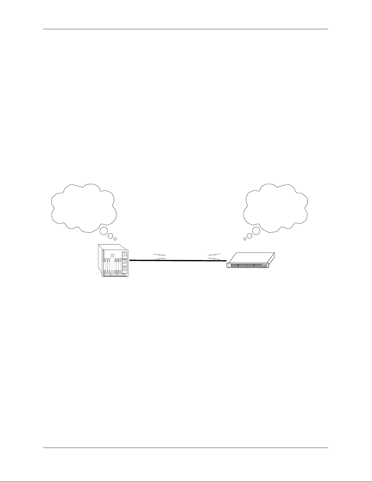
When a router starts, it uses the OSPF Hello Protocol to discover neighbors. The router sends Hello packets to its neighbors, and in turn receives their Hello packets. On broadcast and point-to-point networks, the
router dynamically detects its neighboring routers by sending Hello packets to a multicast address. On
non-broadcast and point-to-multipoint networks, some configuration information is necessary in order to
configure neighbors. On all networks (broadcast or non-broadcast), the Hello Protocol also elects a designated router for the network.
Hello. Please respond...
Are you a neighbor...
My link state is...
Hello. Please respond...
Are you a neighbor...
My link state is...
OSPF Hello Protocol
The router will attempt to form full adjacencies with all of its newly acquired neighbors. Only some pairs,
however, will be successful in forming full adjacencies. Topological databases are synchronized between
pairs of fully adjacent routers.
Adjacencies control the distribution of routing protocol packets. Routing protocol packets are sent and
received only on adjacencies. In particular, distribution of topological database updates proceeds along
adjacencies.
Link state is also advertised when a router’s state changes. A router’s adjacencies are reflected in the
contents of its link state advertisements. This relationship between adjacencies and link state allows the
protocol to detect downed routers in a timely fashion.
Link state advertisements are flooded throughout the AS. The flooding algorithm ensures that all routers
have exactly the same topological database. This database consists of the collection of link state advertisements received from each router belonging to the area. From this database each router calculates a shortest-path tree, with itself as root. This shortest-path tree in turn yields a routing table for the protocol.
page 1-8 OmniSwitch 6800/6850/9000 Advanced Routing Configuration Guide June 2007
Page 27
Configuring OSPF OSPF Overview
OSPF Areas
OSPF allows collections of contiguous networks and hosts to be grouped together as an area. Each area
runs a separate copy of the basic link-state routing algorithm (usually called SPF). This means that each
area has its own topological database, as explained in the previous section.
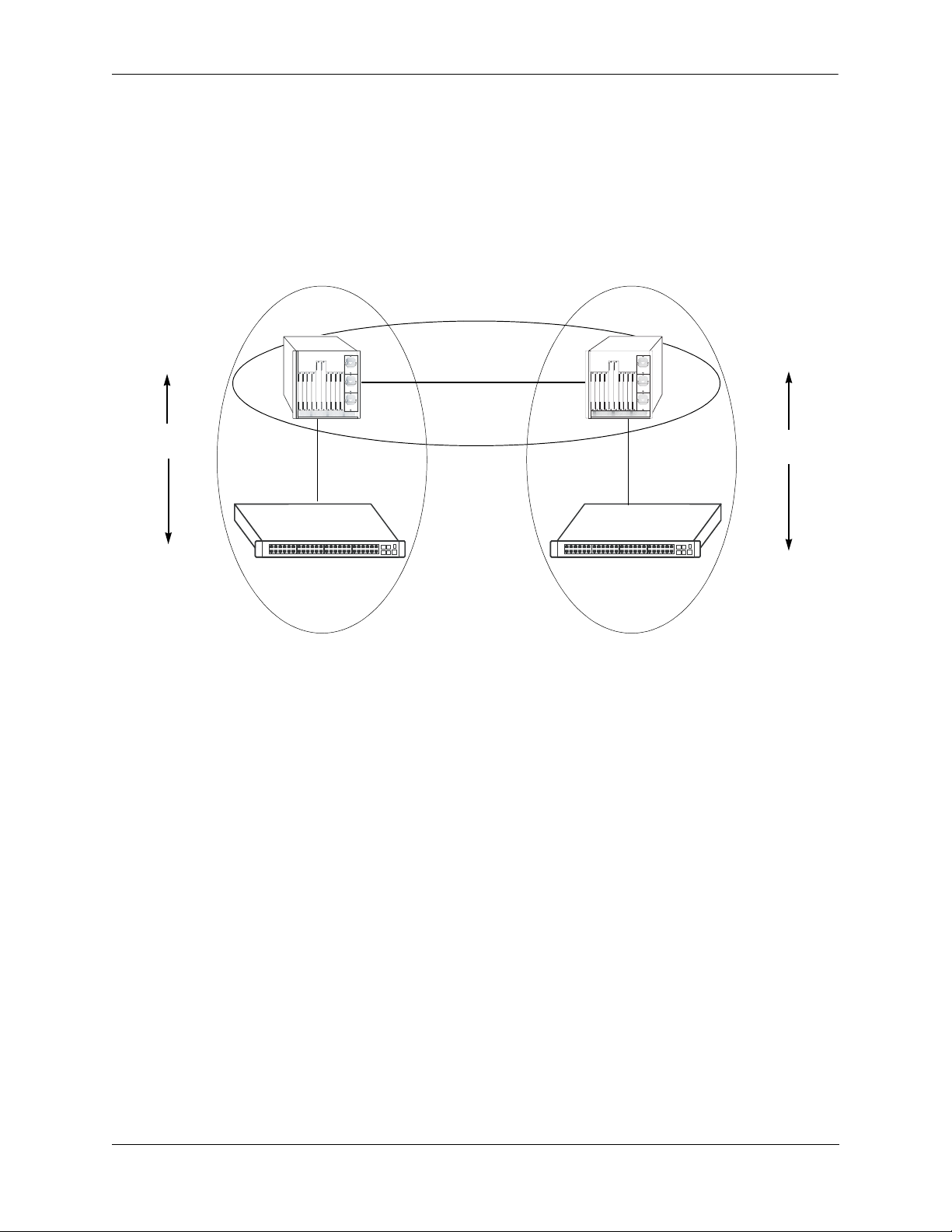
Inter-Area Routing
Intra-Area
Routing
Router 1
Link State
Messages
Router 2
Area 1
Backbone
Area 2
Intra-Area
Routing
Router 3
Link State
Messages
Router 4
OSPF Intra-Area and Inter-Area Routing
An area’s topology is visible only to the members of the area. Conversely, routers internal to a given area
know nothing of the detailed topology external to the area. This isolation of knowledge enables the protocol to reduce routing traffic by concentrating on small areas of an AS, as compared to treating the entire
AS as a single link-state domain.
Areas cause routers to maintain a separate topological database for each area to which they are connected.
(Routers connected to multiple areas are called area border routers). Two routers belonging to the same
area have identical area topological databases.
Different areas communicate with each other through a backbone. The backbone consists of routers with
contacts between multiple areas. A backbone must be contiguous (i.e., it must be linked to all areas).
The backbone is responsible for distributing routing information between areas. The backbone itself has
all of the properties of an area. The topology of the backbone is invisible to each of the areas, while the
backbone itself knows nothing of the topology of the areas.
All routers in an area must agree on that area’s parameters. Since a separate copy of the link-state algorithm is run in each area, most configuration parameters are defined on a per-router basis. All routers
belonging to an area must agree on that area’s configuration. Misconfiguration will keep neighbors from
forming adjacencies between themselves, and OSPF will not function.
OmniSwitch 6800/6850/9000 Advanced Routing Configuration Guide June 2007 page 1-9
Page 28

OSPF Overview Configuring OSPF
Classification of Routers
When an AS is split into OSPF areas, the routers are further divided according to function into the following four overlapping categories:
• Internal routers. A router with all directly connected networks belonging to the same area. These
routers run a single copy of the SPF algorithm.
• Area border routers. A router that attaches to multiple areas. Area border routers run multiple copies
of the SPF algorithm, one copy for each attached area. Area border routers condense the topological
information of their attached areas for flooding to other areas.
• Backbone routers. A router that has an interface to the backbone. This includes all routers that inter-
face to more than one area (i.e., area border routers). However, backbone routers do not have to be area
border routers. Routers with all interfaces connected to the backbone are considered to be internal routers.
• AS boundary routers. A router that exchanges routing information with routers belonging to other
Autonomous Systems. Such a router has AS external routes that are advertised throughout the Autonomous System. The path to each AS boundary router is known by every router in the AS. This classification is completely independent of the previous classifications (i.e., internal, area border, and
backbone routers). AS boundary routers may be internal or area border routers, and may or may not
participate in the backbone.
Virtual Links
It is possible to define areas in such a way that the backbone is no longer contiguous. (This is not an ideal
OSPF configuration, and maximum effort should be made to avoid this situation.) In this case the system
administrator must restore backbone connectivity by configuring virtual links.
Virtual links can be configured between any two backbone routers that have a connection to a common
non-backbone area. The protocol treats two routers joined by a virtual link as if they were connected by an
unnumbered point-to-point network. The routing protocol traffic that flows along the virtual link uses
intra-area routing only, and the physical connection between the two routers is not managed by the
network administrator (i.e., there is no dedicated connection between the routers as there is with the OSPF
backbone).
Router B
Backbone
Backbone
Router A
Area 1
Virtual Link
OSPF Routers Connected with a Virtual Link
In the above diagram, Router A and Router B are connected via a virtual link in Area 1, which is known as
a transit area. See “Creating Virtual Links” on page 1-24 for more information.
page 1-10 OmniSwitch 6800/6850/9000 Advanced Routing Configuration Guide June 2007
Page 29
Configuring OSPF OSPF Overview
Stub Areas
OSPF allows certain areas to be configured as stub areas. A stub area is an area with routers that have no
AS external Link State Advertisements (LSAs).
In order to take advantage of the OSPF stub area support, default routing must be used in the stub area.
This is accomplished by configuring only one of the stub area’s border routers to advertise a default route
into the stub area. The default routes will match any destination that is not explicitly reachable by an intraarea or inter-area path (i.e., AS external destinations).
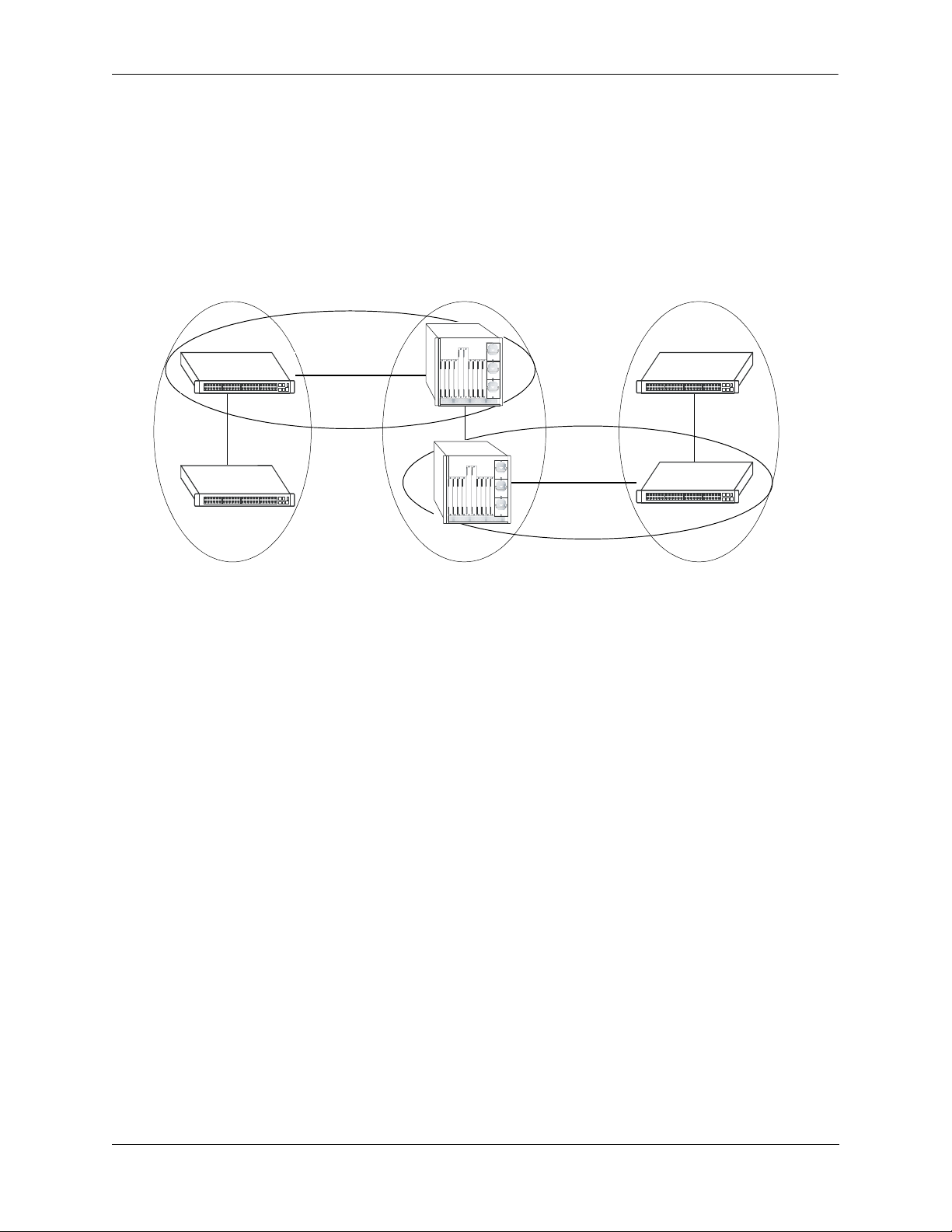
Backbone
Backbone
Area 1
(stub)
Area 2
Area 3
(stub)
OSPF Stub Area
Area 1 and Area 3 could be configured as stub areas. Stub areas are configured using the OSPF ip ospf area
command, described in “Creating an Area” on page 1-18. For more overview information on areas, see “OSPF
Areas” on page 1-9.
The OSPF protocol ensures that all routers belonging to an area agree on whether the area has been
configured as a stub. This guarantees that no confusion will arise in the flooding of AS external advertisements.
Two restrictions on the use of stub areas are:
• Virtual links cannot be configured through stub areas.
• AS boundary routers cannot be placed internal to stub areas.
OmniSwitch 6800/6850/9000 Advanced Routing Configuration Guide June 2007 page 1-11
Page 30

OSPF Overview Configuring OSPF
Not-So-Stubby-Areas
NSSA, or not-so-stubby area, is an extension to the base OSPF specification and is defined in RFC 1587.
An NSSA is similar to a stub area in many ways: AS-external LSAs are not flooded into an NSSA and
virtual links are not allowed in an NSSA. The primary difference is that selected external routing information can be imported into an NSSA and then redistributed into the rest of the OSPF routing domain. These
routes are imported into the NSSA using a new LSA type: Type-7 LSA. Type-7 LSAs are flooded within
the NSSA and are translated at the NSSA boundary into AS-external LSAs so as to convey the external
routing information to other areas.
NSSAs enable routers with limited resources to participate in OSPF routing while also allowing the import
of a selected number of external routes into the area. For example, an area which connects to a small external routing domain running RIP may be configured as an NSSA. This will allow the import of RIP routes
into this area and the rest of the OSPF routing domain and at the same time, prevent the flooding of other
external routing information (learned, for example, through RIP) into this area.
All routers in an NSSA must have their OSPF area defined as an NSSA. To configure otherwise will
ensure that the router will be unsuccessful in establishing an adjacent in the OSPF domain.
Totally Stubby Areas
In Totally Stubby Areas the ABR advertises a default route to the routers in the totally stubby area but
does not advertise any inter-area or external LSAs. As a result, routers in a totally stubby area know only
the routes for destination networks in the stub area and have a default route for any other destination
outside the stub.
Note. Virtual links cannot be configured through totally stubby areas.
The router memory is saved when using stub area networks by filtering Type 4 and 5 LSAs. This concept
has been extended with Totally Stubby Areas by filtering Type 3 LSAs (Network Summary LSA) in addition to Type 4 and 5 with the exception of one single Type 3 LSA used to advertise a default route within
the area.
The following is an example of a simple totally stubby configuration with Router B being an ABR
between the backbone area 0 and the stub area 1. Router A is in area 1.1.1.1, totally stubby area:
OSPF Area 0
192.168.50.0/24
192.168.12.1
Router A Router B
OSPF Area 1
Totally Stubby
192.168.12.2
Totally Stubby Area Example
Note. See “Configuring a Totally Stubby Area” on page 1-20 for information on configuring Totally
Stubby Areas.
page 1-12 OmniSwitch 6800/6850/9000 Advanced Routing Configuration Guide June 2007
Page 31

Configuring OSPF OSPF Overview
Equal Cost Multi-Path (ECMP) Routing
Using information from its continuously updated databases, OSPF calculates the shortest path to a given
destination. Shortest path is determined from metric values at each hop along a path. At times, two or
more paths to the same destination will have the same metric cost.
In the network illustration below, there are two paths from Source router A to Destination router B. One
path traverses two hops at routers X and Y and the second path traverses two hops at M and N. If the total
cost through X and Y to B is the same as the cost via M and N to B, then these two paths have equal cost.
In this version of OSPF both paths will be stored and used to transmit data.
XY
A-> X-> Y-> B = A-> M-> N-> B
Source (A) Destination (B)
MN
Multiple Equal Cost Paths
Delivery of packets along equal paths is based on flows rather than a round-robin scheme. Equal cost is
determined based on standard routing metrics. However, other variables, such as line speed, are not
considered. So it is possible for OSPF to decide two paths have an equal cost even though one may
contain faster links than another.
Non Broadcast OSPF Routing
OSPF can operate in two modes on non-broadcast networks: NBMA and point-to-multipoint. The interface type for the corresponding network segment should be set to non-broadcast or point-to-multipoint,
respectively.
For non-broadcast networks neighbors should be statically configured. For NBMA neighbors the eligibility option must be enabled for the neighboring router to participate in Designated Router (DR) election.
For the correct working of an OSPF NBMA network, a fully meshed network is mandatory. Also, the
neighbor eligibility configuration for a router on every other router should match the routers interface
priority configuration.
See “Configuring Static Neighbors” on page 1-32 for more information and setting up static neighbors.
OmniSwitch 6800/6850/9000 Advanced Routing Configuration Guide June 2007 page 1-13
Page 32

OSPF Overview Configuring OSPF
Graceful Restart on Stacks with Redundant Switches
OmniSwitch 6800 and OmniSwitch 6850 stacks with two or more switches can support redundancy where
if the primary switch fails or goes offline for any reason, the secondary switch is instantly notified. The
secondary switch automatically assumes the primary role. This switch between the primary and secondary
switches is known as takeover.
When a takeover occurs, which can be planned (e.g., the users performs the takeover) or unplanned (e.g.,
the primary switch unexpectedly fails), an OSPF router must reestablish full adjacencies with all its previously fully adjacent neighbors. This time period between the restart and the reestablishment of adjacencies is termed graceful restart.
In the network illustration below, a helper router, Router Y, monitors the network for topology changes.
As long as there are none, it continues to advertise its LSAs as if the restarting router, Router X, had
remained in continuous OSPF operation (i.e., Router Y’s LSAs continue to list an adjacency to Router X
over network segment S, regardless of the adjacency’s current synchronization state).
Router B
Restarting Router X
Network Segment S
Router A
Helping Router Y
Router C
OSPF Graceful Restart Helping and Restarting Router Example
If the restarting router, Router X, was the Designated Router (DR) on network segment S when the helping relationship began, the helper neighbor, Router Y, maintains Router X as the DR until the helping relationship is terminated. If there are multiple adjacencies with the restarting Router X, Router Y will act as a
helper on all other adjacencies.
Continuous forwarding during a graceful restart depends on several factors. If the secondary module has a
different router MAC than the primary module, or if one or more ports of a VLAN belonged to the
primary module, spanning tree re-convergence might disrupt forwarding state, even though OSPF
performs a graceful restart.
Note. See “Configuring Redundant Switches in a Stack for Graceful Restart” on page 1-33 for more infor-
mation on configuring graceful restart.
page 1-14 OmniSwitch 6800/6850/9000 Advanced Routing Configuration Guide June 2007
Page 33

Configuring OSPF OSPF Overview
Graceful Restart on Switches with Redundant CMMs
OmniSwitch 9000 chassis with two Chassis management Modules (CMMs) can support redundancy
where if the primary CMM fails or goes offline for any reason, the secondary CMM is instantly notified.
The secondary CMM automatically assumes the primary role. This switch between the primary and
secondary CMMs is known as takeover.
When a takeover occurs, which can be planned (e.g., the users performs the takeover) or unplanned (e.g.,
the primary CMM unexpectedly fails), an OSPF router must reestablish full adjacencies with all its previously fully adjacent neighbors. This time period between the restart and the reestablishment of adjacencies is termed graceful restart.
In the network illustration below, a helper router, Router Y, monitors the network for topology changes.
As long as there are none, it continues to advertise its LSAs as if the restarting router, Router X, had
remained in continuous OSPF operation (i.e., Router Y’s LSAs continue to list an adjacency to Router X
over network segment S, regardless of the adjacency’s current synchronization state).
Router B
Restarting router X
Network Segment S
Router A
Helping router Y
Router C
OSPF Graceful Restart Helping and Restarting Router Example
If the restarting router, Router X, was the Designated Router (DR) on network segment S when the helping relationship began, the helper neighbor, Router Y, maintains Router X as the DR until the helping relationship is terminated. If there are multiple adjacencies with the restarting Router X, Router Y will act as a
helper on all other adjacencies.
Note. See “Configuring Redundant CMMs for Graceful Restart” on page 1-34 for more information on
configuring graceful restart.
OmniSwitch 6800/6850/9000 Advanced Routing Configuration Guide June 2007 page 1-15
Page 34

Configuring OSPF Configuring OSPF
Configuring OSPF
Configuring OSPF on a router requires several steps. Depending on your requirements, you may not need
to perform all of the steps listed below.
By default, OSPF is disabled on the router. Configuring OSPF consists of these tasks:
• Set up the basics of the OSPF network by configuring the required VLANs, assigning ports to the
VLANs, and assigning router identification numbers to the routers involved. This is described in
“Preparing the Network for OSPF” on page 1-17.
• Enable OSPF. When the image file for advanced routing is installed, you must load the code and enable
OSPF. The commands for enabling OSPF are described in “Activating OSPF” on page 1-17.
• Create an OSPF area and the backbone. The commands to create areas and backbones are described in
“Creating an OSPF Area” on page 1-18.
• Set area parameters (optional). OSPF will run with the default area parameters, but different networks
may benefit from modifying the parameters. Modifying area parameters is described in “Configuring
Stub Area Default Metrics” on page 1-20.
• Create OSPF interfaces. OSPF interfaces are created and assigned to areas. Creating interfaces is
described in “Creating an Interface” on page 1-21, and assigning interfaces is described in “Assigning
an Interface to an Area” on page 1-21.
• Set interface parameters (optional). OSPF will run with the default interface parameters, but different
networks may benefit from modifying the parameters. Also, it is possible to set authentication on an
interface. Setting interface authentication is described in “Interface Authentication” on page 1-22, and
modifying interface parameters is described in “Modifying Interface Parameters” on page 1-23.
• Configure virtual links (optional). A virtual link is used to establish backbone connectivity when two
backbone routers are not physically contiguous. To create a virtual link, see “Creating Virtual Links”
on page 1-24.
• Create a redistribution policy and enable the same using route maps (optional). To create route maps,
see “Configuring Redistribution” on page 1-25.
• Configure router capabilities (optional). There are several commands that influence router operation.
These are covered briefly in a table in “Configuring Router Capabilities” on page 1-31.
• Create static neighbors (optional). These commands allow you to statically configure neighbors. See
“Configuring Static Neighbors” on page 1-32.
• Configure redundant switches for graceful OSPF restart (optional). Configuring switches with redun-
dant switches for graceful restart is described in “Configuring Redundant Switches in a Stack for
Graceful Restart” on page 1-33.
• Configure redundant CMMs for graceful OSPF restart (optional). Configuring switches with redundant
switches for graceful restart is described in “Configuring Redundant CMMs for Graceful Restart” on
page 1-34.
At the end of the chapter is a simple OSPF network diagram with instructions on how it was created on a
router-by-router basis. See “OSPF Application Example” on page 1-35 for more information.
page 1-16 OmniSwitch 6800/6850/9000 Advanced Routing Configuration Guide June 2007
Page 35

Configuring OSPF Configuring OSPF
Preparing the Network for OSPF
OSPF operates on top of normal switch functions, using existing ports, virtual ports, VLANs, etc. The
following network components should already be configured:
• Configure VLANs that are to be used in the OSPF network. VLANS should be created for both the
backbone interfaces and all other connected devices that will participate in the OSPF network. A
VLAN should exist for each instance in which the backbone connects two routers. VLAN configuration is described in “Configuring VLANs,” in the OmniSwitch 6800/6850/9000 Network Configura-
tion Guide.
• Assign IP interfaces to the VLANs. IP interfaces, or router ports, must be assigned to the VLAN.
Assigning IP interfaces is described in “Configuring VLANs,” in the OmniSwitch 6800/6850/9000
Network Configuration Guide.
• Assign ports to the VLANs. The physical ports participating in the OSPF network must be assigned to
the created VLANs. Assigning ports to a VLAN is described in “Assigning Ports to VLANs,” in the
OmniSwitch 6800/6850/9000 Network Configuration Guide.
• Set the router identification number. (optional) The routers participating in the OSPF network must
be assigned a router identification number. This number can be any number, as long as it is in standard
dotted decimal format (e.g., 1.1.1.1). Router identification number assignment is discussed in “Configuring IP,” in the OmniSwitch 6800/6850/9000 Network Configuration Guide. If this is not done, the
router identification number is automatically the primary interface address.
Activating OSPF
For OSPF to run on the router, the advanced routing image must be installed. (For information on how to
install image files, see the OmniSwitch 6800/6850/9000 Switch Management Guide.)
After the image file has been installed onto the router, you will need to load the OSPF software into
memory and enable it, as described below.
Loading the Software
To load the OSPF software into the router’s running configuration, enter the ip load ospf command at the
system prompt:
-> ip load ospf
The OPSF software is now loaded into memory, and can be enabled.
Enabling OSPF
Once the OSPF software has been loaded into the router’s running configuration (either through the CLI
or on startup), it must be enabled. To enable OSPF on a router, enter the ip ospf status command at the
CLI prompt, as shown:
-> ip ospf status enable
Once OSPF is enabled, you can begin to set up OSPF parameters. To disable OSPF, enter the following:
-> ip ospf status disable
OmniSwitch 6800/6850/9000 Advanced Routing Configuration Guide June 2007 page 1-17
Page 36

Configuring OSPF Configuring OSPF
Removing OSPF from Memory
To remove OSPF from the router memory, it is necessary to manually edit the boot.cfg file. The boot.cfg
file is an ASCII text-based file that controls many of the switch parameters. Open the file and delete all
references to OSPF.
For the operation to take effect the switch needs to be rebooted.
Creating an OSPF Area
OSPF allows a set of network devices in an AS system to be grouped together in areas.
There can be more than one router in an area. Likewise, there can be more than one area on a single router
(in effect, making the router the Area Border Router (ABR) for the areas involved), but standard networking design does not recommended that more than three areas be handled on a single router.
Areas are named using 32-bit dotted decimal format (e.g., 1.1.1.1). Area 0.0.0.0 is reserved for the backbone.
Creating an Area
To create an area and associate it with a router, enter the ip ospf area command with the area identifica-
tion number at the CLI prompt, as shown:
-> ip ospf area 1.1.1.1
Area 1.1.1.1 will now be created on the router with the default parameters.
The backbone is always area 0.0.0.0. To create this area on a router, you would use the above command,
but specify the backbone, as shown:
-> ip ospf area 0.0.0.0
The backbone would now be attached to the router, making it an Area Border Router (ABR).
Enabling an Area
Once an area is created, it must be enabled using the ip ospf area status command, as shown:
-> ip ospf area 0.0.0.0 status enable
Specifying an Area Type
When creating areas, an area type can be specified (normal, stub, or NSSA). Area types are described
above in “OSPF Areas” on page 1-9. To specify an area type, use the ip ospf area command as shown:
-> ip ospf area 1.1.1.1 type stub
Note. By default, an area is a normal area. The type keyword would be used to change a stub or NSSA
area into a normal area.
page 1-18 OmniSwitch 6800/6850/9000 Advanced Routing Configuration Guide June 2007
Page 37

Configuring OSPF Configuring OSPF
Enabling and Disabling Summarization
Summarization can also be enabled or disabled when creating an area. Enabling summarization allows for
ranges to be used by Area Border Routers (ABRs) for advertising routes as a single route rather than
multiple routes, while disabling summarization prevents set ranges from functioning in stub and NSSA
areas. (Configuring ranges is described in “Setting Area Ranges” on page 1-20.)
For example, to enable summarization for Area 1.1.1.1, enter the following:
-> ip ospf area 1.1.1.1 summary enable
To disable summarization for the same area, enter the following:
-> ip ospf area 1.1.1.1 summary disable
Note. By default, an area has summarization enabled. Disabling summarization for an area is useful when
ranges need to be deactivated, but not deleted.
Displaying Area Status
You can check the status of the newly created area by using the show command, as demonstrated:
-> show ip ospf area 1.1.1.1
or
-> show ip ospf area
The first example gives specifics about area 1.1.1.1, and the second example shows all areas configured on
the router.
To display a stub area’s parameters, use the show ip ospf area stub command as follows:
-> show ip ospf area 1.1.1.1 stub
Deleting an Area
To delete an area, enter the ip ospf area command as shown:
-> no ip ospf area 1.1.1.1
OmniSwitch 6800/6850/9000 Advanced Routing Configuration Guide June 2007 page 1-19
Page 38

Configuring OSPF Configuring OSPF
Configuring Stub Area Default Metrics
The default metric configures the type of cost metric that a default area border router (ABR) will advertise
in the default summary Link State Advertisement (LSA). Use the ip ospf area default-metric command
to create or delete a default metric for stub or Not So Stubby Area (NSSA) area. Specify the stub area and
select a cost value or a route type, as shown:
-> ip ospf area 1.1.1.1 default-metric 0 cost 50
or
-> ip ospf area 1.1.1.1 default-metric 0 type type1
A route has a preset metric associated to it depending on its type. The first example, the stub area is given
a default metric of 0 (this is Type of Service 0) and a cost of 50 added to routes from the area. The second
example specifies that the cost associated with Type 1 routes should be applied to routes from the area.
Note. At this time, only the default metric of ToS 0 is supported.
To remove the area default-metric setting, enter the ip ospf area default-metric command using the no
command, as shown:
-> no ip ospf area 1.1.1.1 default-metric 0
Setting Area Ranges
Area ranges are used to summarize many area routes into a single advertisement at an area boundary.
Ranges are advertised as summaries or NSSAs. Ranges also act as filters that either allow the summary to
be advertised or not. Ranges are created using the ip ospf area range command. An area and the summary
IP address and IP mask must be specified. For example, to create a summary range with IP address
192.5.40.1 and an IP mask of 255.255.255.0 for area 1.1.1.1, the following commands would be entered at
the CLI prompt:
-> ip ospf area 1.1.1.1 range summary 192.5.40.1 255.255.255.0
-> ip ospf area 1.1.1.1 range summary 192.5.40.1 255.255.255.0 effect noMatching
To view the configured ranges for an area, use the show ip ospf area range command as demonstrated:
-> show ip ospf area 1.1.1.1 range
Configuring a Totally Stubby Area
In order to configure a totally stubby area you need to configure the area as stub on the ABR and disable
summarization. By doing so the ABR will generate a default route in the totally stubby area. In addition,
the other routers within the totally stubby area must only have their area configured as stub.
For example, to configure the simple totally stubby configuration shown in the figure in “Configuring a
Totally Stubby Area” on page 1-20 where Router B is an ABR between the backbone area 0 and the stub
area 1 and Router A is in Totally Stubby Area 1.1.1.1 follow the steps below:
1 Enter the following commands on Router B:
-> ip load ospf
-> ip ospf area 0.0.0.0
-> ip ospf area 0.0.0.0 status enable
-> ip ospf area 1.1.1.1
page 1-20 OmniSwitch 6800/6850/9000 Advanced Routing Configuration Guide June 2007
Page 39

Configuring OSPF Configuring OSPF
-> ip ospf area 1.1.1.1 type stub
-> ip ospf area 1.1.1.1 summary disable
-> ip ospf area 1.1.1.1 status enable
-> ip ospf area 1.1.1.1 default-metric 0
-> ip ospf interface 192.168.12.2
-> ip ospf interface 192.168.12.2 area 1.1.1.1
-> ip ospf interface 192.168.12.2 status enable
-> ip ospf interface 192.168.50.2
-> ip ospf interface 192.168.50.2 area 0.0.0.0
-> ip ospf interface 192.168.50.2 status enable
-> ip ospf status enable
2 Enter the following on Router A:
-> ip load ospf
-> ip ospf area 1.1.1.1
-> ip ospf area 1.1.1.1 type stub
-> ip ospf area 1.1.1.1 status enable
-> ip ospf interface 192.168.12.1
-> ip ospf interface 192.168.12.1 area 1.1.1.1
-> ip ospf interface 192.168.12.1 status enable
-> ip ospf status enable
Creating OSPF Interfaces
Once areas have been established, interfaces need to be created and assigned to the areas.
Creating an Interface
To create an interface, enter the ip ospf interface command with an IP address or interface name, as
shown:
-> ip ospf interface 120.5.80.1
-> ip ospf interface vlan-213
Note. The interface name cannot have spaces.
The interface can be deleted the by using the no keyword, as shown:
-> no ip ospf interface 120.5.80.1
Assigning an Interface to an Area
Once an interface is created, it must be assigned to an area. (Creating areas is described in “Creating an
Area” on page 1-18 above.)
To assign an interface to an area, enter the ip ospf interface area command with the interface IP address
or interface name and area identification number at the CLI prompt. For example to add interface
120.5.80.1 to area 1.1.1.1, enter the following:
-> ip ospf interface 120.5.80.1 area 1.1.1.1
An interface can be removed from an area by reassigning it to a new area.
OmniSwitch 6800/6850/9000 Advanced Routing Configuration Guide June 2007 page 1-21
Page 40

Configuring OSPF Configuring OSPF
Once an interface has been created and enabled, you can check its status and configuration by using the
show ip ospf interface command, as demonstrated:
-> show ip ospf interface 120.5.80.1
Instructions for configuring authentication are given in “Interface Authentication” on page 1-22, and interface parameter options are described in “Modifying Interface Parameters” on page 1-23.
Activating an Interface
Once the interface is created and assigned to an area, it must be activated using the ip ospf interface
status command with the interface IP address or interface name, as shown:
-> ip ospf interface 120.5.80.1 status enable
The interface can be disabled using the disable keyword in place of the enable keyword.
Interface Authentication
OSPF allows for the use of authentication on configured interfaces. When authentication is enabled, only
neighbors using the same type of authentication and the matching passwords or keys can communicate.
There are two types of authentication: simple and MD5. Simple authentication requires only a text string
as a password, while MD5 is a form of encrypted authentication that requires a key and a password. Both
types of authentication require the use of more than one command.
Simple Authentication
To enable simple authentication on an interface, enter the ip ospf interface auth-type command with the
interface IP address or interface name, as shown:
-> ip ospf interface 120.5.80.1 auth-type simple
Once simple authentication is enabled, the password must be set with the ip ospf interface auth-key
command, as shown:
-> ip ospf interface 120.5.80.1 auth-key test
In the above instance, only other interfaces with simple authentication and a password of “test” will be
able to use the configured interface.
MD5 Encryption
To configure the same interface for MD5 encryption, enter the ip ospf interface auth-type as shown:
-> ip ospf interface 120.5.80.1 auth-type md5
Once MD5 authentication is set, a key identification and key string must be set with the ip ospf interface
md5 key command. For example to set interface 120.5.80.1 to use MD5 authentication with a key identifi-
cation of 7 and key string of “test”, enter:
-> ip ospf interface 120.5.80.1 md5 7
and
-> ip ospf interface 120.5.80.1 md5 7 key "test"
page 1-22 OmniSwitch 6800/6850/9000 Advanced Routing Configuration Guide June 2007
Page 41

Configuring OSPF Configuring OSPF
Note that setting the key ID and key string must be done in two separate commands. Once the key ID and
key string have been set, MD5 authentication is enabled. To disable it, use the ip ospf interface md5
command, as shown:
-> ip ospf interface 120.5.80.1 md5 7 disable
To remove all authentication, enter the ip ospf interface auth-type as follows:
-> ip ospf interface 120.5.80.1 auth-type none
Modifying Interface Parameters
There are several interface parameters that can be modified on a specified interface. Most of these deal
with timer settings.
The cost parameter and the priority parameter help to determine the cost of the route using this interface,
and the chance that this interface’s router will become the designated router, respectively.
The following table shows the various interface parameters that can be set:
ip ospf interface dead-interval Configures OSPF interface dead interval. If no hello packets are
received in this interval from a neighboring router the neighbor is considered dead.
ip ospf interface hello-interval Configures the OSPF interface interval for NBMA segments.
ip ospf interface cost Configures the OSPF interface cost. A cost metric refers to the net-
work path preference assigned to certain types of traffic.
ip ospf interface poll-interval Configures the OSPF poll interval.
ip ospf interface priority Configures the OSPF interface priority. The priority number helps
determine if this router will become the designated router.
ip ospf interface retrans-interval Configures OSPF interface retransmit interval. The number of sec-
onds between link state advertisement retransmissions for adjacencies
belonging to this interface.
ip ospf interface transit-delay Configures the OSPF interface transit delay. The estimated number of
seconds required to transmit a link state update over this interface.
These parameters can be added any time. (See “Creating OSPF Interfaces” on page 1-21 for more information.) For example, to set an the dead interval to 50 and the cost to 100 on interface 120.5.80.1, enter
the following:
-> ip ospf interface 120.5.80.1 dead-interval 50 cost 100
To set an the poll interval to 25, the priority to 100, and the retransmit interval to 10 on interface
120.5.80.1, enter the following:
-> ip ospf interface 120.5.80.1 poll-interval 25 priority 100 retrans-interval
10
To set the hello interval to 5000 on interface 120.5.80.1, enter the following:
-> ip ospf interface 120.5.80.1 hello-interval 5000
To reset any parameter to its default value, enter the keyword with no parameter value, as shown:
-> ip ospf interface 120.5.80.1 dead-interval
OmniSwitch 6800/6850/9000 Advanced Routing Configuration Guide June 2007 page 1-23
Page 42

Configuring OSPF Configuring OSPF
Note. Although you can configure several parameters at once, you can only reset them to the default one at
a time.
Creating Virtual Links
A virtual link is a link between two backbones through a transit area. Use the ip ospf virtual-link
command to create or delete a virtual link.
Accepted network design theory states that virtual links are the option of last resort. For more information
on virtual links, see “Virtual Links” on page 1-10 and refer to the figure on page 1-10.
Creating a Virtual Link
To create a virtual link, commands must be submitted to the routers at both ends of the link. The router
being configured should point to the other end of the link, and both routers must have a common area.
When entering the ip ospf virtual-link command, it is necessary to enter the Router ID of the far end of
the link, and the area ID that both ends of the link share.
For example, a virtual link needs to be created between Router A (router ID 1.1.1.1) and Router B (router
ID 2.2.2.2). We must:
1 Establish a transit area between the two routers using the commands discussed in “Creating an OSPF
Area” on page 1-18 (in this example, we will use Area 0.0.0.1).
2 Then use the ip ospf virtual-link command on Router A as shown:
-> ip ospf virtual-link 0.0.0.1 2.2.2.2
3 Next, enter the following command on Router B:
-> ip ospf virtual-link 0.0.0.1 1.1.1.1
Now there is a virtual link across Area 0.0.0.1 linking Router A and Router B.
4 To display virtual links configured on a router, enter the following show command:
-> show ip ospf virtual-link
5 To delete a virtual link, enter the ip ospf virtual-link command with the area and far end router infor-
mation, as shown:
-> no ip ospf virtual-link 0.0.0.1 2.2.2.2
Modifying Virtual Link Parameters
There are several parameters for a virtual link (such as authentication type and cost) that can be modified
at the time of the link creation. They are described in the ip ospf virtual-link command description. These
parameters are identical in function to their counterparts in the section “Modifying Interface Parameters”
on page 1-23.
page 1-24 OmniSwitch 6800/6850/9000 Advanced Routing Configuration Guide June 2007
Page 43

Configuring OSPF Configuring OSPF
Configuring Redistribution
It is possible to learn and advertise IPv4 routes between different protocols. Such a process is referred to
as route redistribution and is configured using the ip redist command.
Redistribution uses route maps to control how external routes are learned and distributed. A route map
consists of one or more user-defined statements that can determine which routes are allowed or denied
access to the network. In addition a route map may also contain statements that modify route parameters
before they are redistributed.
When a route map is created, it is given a name to identify the group of statements that it represents. This
name is required by the ip redist command. Therefore, configuring route redistribution involves the
following steps:
1 Create a route map, as described in “Using Route Maps” on page 1-25.
2 Configure redistribution to apply a route map, as described in “Configuring Route Map Redistribu-
tion” on page 1-29.
Note. An OSPF router automatically becomes an Autonomous System Border Router (ASBR) when redistribution is configured on the router.
Using Route Maps
A route map specifies the criteria that are used to control redistribution of routes between protocols. Such
criteria is defined by configuring route map statements. There are three different types of statements:
• Action. An action statement configures the route map name, sequence number, and whether or not
redistribution is permitted or denied based on route map criteria.
• Match. A match statement specifies criteria that a route must match. When a match occurs, then the
action statement is applied to the route.
• Set. A set statement is used to modify route information before the route is redistributed into the
receiving protocol. This statement is only applied if all the criteria of the route map is met and the
action permits redistribution.
The ip route-map command is used to configure route map statements and provides the following action,
match, and set parameters:
ip route-map action ... ip route-map match ... ip route-map set ...
permit
deny
ip-address
ip-nexthop
ipv6-address
ipv6-nexthop
tag
ipv4-interface
ipv6-interface
metric
route-type
metric
metric-type
tag
community
local-preference
level
ip-nexthop
ipv6-nexthop
Refer to the “IP Commands” chapter in the OmniSwitch CLI Reference Guide for more information about
the ip route-map command parameters and usage guidelines.
OmniSwitch 6800/6850/9000 Advanced Routing Configuration Guide June 2007 page 1-25
Page 44

Configuring OSPF Configuring OSPF
Once a route map is created, it is then applied using the ip redist command. See “Configuring Route Map
Redistribution” on page 1-29 for more information.
Creating a Route Map
When a route map is created, it is given a name (up to 20 characters), a sequence number, and an action
(permit or deny). Specifying a sequence number is optional. If a value is not configured, then the number
50 is used by default.
To create a route map, use the ip route-map command with the action parameter. For example,
-> ip route-map ospf-to-bgp sequence-number 10 action permit
The above command creates the ospf-to-bgp route map, assigns a sequence number of 10 to the route
map, and specifies a permit action.
To optionally filter routes before redistribution, use the ip route-map command with a match parameter
to configure match criteria for incoming routes. For example,
-> ip route-map ospf-to-bgp sequence-number 10 match tag 8
The above command configures a match statement for the ospf-to-bgp route map to filter routes based on
their tag value. When this route map is applied, only OSPF routes with a tag value of eight are redistributed into the BGP network. All other routes with a different tag value are dropped.
Note. Configuring match statements is not required. However, if a route map does not contain any match
statements and the route map is applied using the ip redist command, the router redistributes all routes
into the network of the receiving protocol.
To modify route information before it is redistributed, use the ip route-map command with a set parameter. For example,
-> ip route-map ospf-to-bgp sequence-number 10 set tag 5
The above command configures a set statement for the ospf-to-bgp route map that changes the route tag
value to five. Because this statement is part of the ospf-to-bgp route map, it is only applied to routes that
have an existing tag value equal to eight.
The following is a summary of the commands used in the above examples:
-> ip route-map ospf-to-bgp sequence-number 10 action permit
-> ip route-map ospf-to-bgp sequence-number 10 match tag 8
-> ip route-map ospf-to-bgp sequence-number 10 set tag 5
To verify a route map configuration, use the show ip route-map command:
-> show ip route-map
Route Maps: configured: 1 max: 200
Route Map: ospf-to-bgp Sequence Number: 10 Action permit
match tag 8
set tag 5
page 1-26 OmniSwitch 6800/6850/9000 Advanced Routing Configuration Guide June 2007
Page 45

Configuring OSPF Configuring OSPF
Deleting a Route Map
Use the no form of the ip route-map command to delete an entire route map, a route map sequence, or a
specific statement within a sequence.
To delete an entire route map, enter no ip route-map followed by the route map name. For example, the
following command deletes the entire route map named redistipv4:
-> no ip route-map redistipv4
To delete a specific sequence number within a route map, enter no ip route-map followed by the route
map name, then sequence-number followed by the actual number. For example, the following command
deletes sequence 10 from the redistipv4 route map:
-> no ip route-map redistipv4 sequence-number 10
Note that in the above example, the redistripv4 route map is not deleted. Only those statements associated
with sequence 10 are removed from the route map.
To delete a specific statement within a route map, enter no ip route-map followed by the route map name,
then sequence-number followed by the sequence number for the statement, then either match or set and
the match or set parameter and value. For example, the following command deletes only the match tag 8
statement from route map redistipv4 sequence 10:
-> no ip route-map redistipv4 sequence-number 10 match tag 8
Configuring Route Map Sequences
A route map may consist of one or more sequences of statements. The sequence number determines which
statements belong to which sequence and the order in which sequences for the same route map are
processed.
To add match and set statements to an existing route map sequence, specify the same route map name and
sequence number for each statement. For example, the following series of commands creates route map
rm_1 and configures match and set statements for the rm_1 sequence 10:
-> ip route-map rm_1 sequence-number 10 action permit
-> ip route-map rm_1 sequence-number 10 match tag 8
-> ip route-map rm_1 sequence-number 10 set metric 1
To configure a new sequence of statements for an existing route map, specify the same route map name
but use a different sequence number. For example, the following command creates a new sequence 20 for
the rm_1 route map:
-> ip route-map rm_1 sequence-number 20 action permit
-> ip route-map rm_1 sequence-number 20 match ipv4-interface to-finance
-> ip route-map rm_1 sequence-number 20 set metric 5
The resulting route map appears as follows:
-> show ip route-map rm_1
Route Map: rm_1 Sequence Number: 10 Action permit
match tag 8
set metric 1
Route Map: rm_1 Sequence Number: 20 Action permit
match ip6 interface to-finance
set metric 5
OmniSwitch 6800/6850/9000 Advanced Routing Configuration Guide June 2007 page 1-27
Page 46

Configuring OSPF Configuring OSPF
Sequence 10 and sequence 20 are both linked to route map rm_1 and are processed in ascending order
according to their sequence number value. Note that there is an implied logical OR between sequences. As
a result, if there is no match for the tag value in sequence 10, then the match interface statement in
sequence 20 is processed. However, if a route matches the tag 8 value, then sequence 20 is not used. The
set statement for whichever sequence was matched is applied.
A route map sequence may contain multiple match statements. If these statements are of the same kind
(e.g., match tag 5, match tag 8, etc.) then a logical OR is implied between each like statement. If the match
statements specify different types of matches (e.g. match tag 5, match ip4 interface to-finance, etc.), then a
logical AND is implied between each statement. For example, the following route map sequence will
redistribute a route if its tag is either 8 or 5:
-> ip route-map rm_1 sequence-number 10 action permit
-> ip route-map rm_1 sequence-number 10 match tag 5
-> ip route-map rm_1 sequence-number 10 match tag 8
The following route map sequence will redistribute a route if the route has a tag of 8 or 5 and the route
was learned on the IPv4 interface to-finance:
-> ip route-map rm_1 sequence-number 10 action permit
-> ip route-map rm_1 sequence-number 10 match tag 5
-> ip route-map rm_1 sequence-number 10 match tag 8
-> ip route-map rm_1 sequence-number 10 match ipv4-interface to-finance
Configuring Access Lists
An IP access list provides a convenient way to add multiple IPv4 or IPv6 addresses to a route map. Using
an access list avoids having to enter a separate route map statement for each individual IP address. Instead,
a single statement is used that specifies the access list name. The route map is then applied to all the
addresses contained within the access list.
Configuring an IP access list involves two steps: creating the access list and adding IP addresses to the list.
To create an IP access list, use the ip access-list command (IPv4) or the ipv6 access-list command (IPv6)
and specify a name to associate with the list. For example,
-> ip access-list ipaddr
-> ipv6 access-list ip6addr
To add addresses to an access list, use the ip access-list address (IPv4) or the ipv6 access-list address
(IPv6) command. For example, the following commands add addresses to an existing access list:
-> ip access-list ipaddr address 16.24.2.1/16
-> ipv6 access-list ip6addr address 2001::1/64
Use the same access list name each time the above commands are used to add additional addresses to the
same access list. In addition, both commands provide the ability to configure if an address and/or its
matching subnet routes are permitted (the default) or denied redistribution. For example:
-> ip access-list ipaddr address 16.24.2.1/16 action deny redist-control allsubnets
-> ipv6 access-list ip6addr address 2001::1/64 action permit redist-control nosubnets
For more information about configuring access list commands, see the “IP Commands” chapter in the
OmniSwitch CLI Reference Guide.
page 1-28 OmniSwitch 6800/6850/9000 Advanced Routing Configuration Guide June 2007
Page 47

Configuring OSPF Configuring OSPF
Configuring Route Map Redistribution
The ip redist command is used to configure the redistribution of routes from a source protocol into the
destination protocol. This command is used on the router that will perform the redistribution.
Note. An OSPF router automatically becomes an Autonomous System Border Router (ASBR) when redistribution is configured on the router.
A source protocol is a protocol from which the routes are learned. A destination protocol is the one into
which the routes are redistributed. Make sure that both protocols are loaded and enabled before configuring redistribution.
Redistribution applies criteria specified in a route map to routes received from the source protocol. Therefore, configuring redistribution requires an existing route map. For example, the following command
configures the redistribution of OSPF routes into the BGP network using the ospf-to-bgp route map:
-> ip redist ospf into bgp route-map ospf-to-bgp
OSPF routes received by the router interface are processed based on the contents of the ospf-to-bgp route
map. Routes that match criteria specified in this route map are either allowed or denied redistribution into
the BGP network. The route map may also specify the modification of route information before the route
is redistributed. See “Using Route Maps” on page 1-25 for more information.
To remove a route map redistribution configuration, use the no form of the ip redist command. For example:
-> no ip ospf into bgp route-map ospf-to-bgp
Use the show ip redist command to verify the redistribution configuration:
-> show ip redist
Source Destination
Protocol Protocol Status Route Map
------------+------------+---------+-------------------LOCAL4 RIP Enabled rip_1
LOCAL4 OSPF Enabled ospf_2
LOCAL4 BGP Enabled bgp_3
BGP OSPF Enabled ospf-to-bgp
Configuring the Administrative Status of the Route Map Redistribution
The administrative status of a route map redistribution configuration is enabled by default. To change the
administrative status, use the status parameter with the ip redist command. For example, the following
command disables the redistribution administrative status for the specified route map:
-> ip redist ospf into bgp route-map ospf-to-bgp status disable
The following command example enables the administrative status:
-> ip redist ospf into bgp route-map ospf-to-bgp status enable
OmniSwitch 6800/6850/9000 Advanced Routing Configuration Guide June 2007 page 1-29
Page 48

Configuring OSPF Configuring OSPF
Route Map Redistribution Example
The following example configures the redistribution of OSPF routes into a BGP network using a route
map (ospf-to-bgp) to filter specific routes:
-> ip route-map ospf-to-bgp sequence-number 10 action deny
-> ip route-map ospf-to-bgp sequence-number 10 match tag 5
-> ip route-map ospf-to-bgp sequence-number 10 match route-type external type2
-> ip route-map ospf-to-bgp sequence-number 20 action permit
-> ip route-map ospf-to-bgp sequence-number 20 match ipv4-interface intf_ospf
-> ip route-map ospf-to-bgp sequence-number 20 set metric 255
-> ip route-map ospf-to-bgp sequence-number 30 action permit
-> ip route-map ospf-to-bgp sequence-number 30 set tag 8
-> ip redist ospf into bgp route-map ospf-to-bgp
The resulting ospf-to-bgp route map redistribution configuration does the following:
• Denies the redistribution of Type 2 external OSPF routes with a tag set to five.
• Redistributes into BGP all routes learned on the intf_ospf interface and sets the metric for such routes
to 255.
• Redistributes into BGP all other routes (those not processed by sequence 10 or 20) and sets the tag for
such routes to eight.
page 1-30 OmniSwitch 6800/6850/9000 Advanced Routing Configuration Guide June 2007
Page 49

Configuring OSPF Configuring OSPF
Configuring Router Capabilities
The following list shows various commands that can be useful in tailoring a router’s performance capabilities. All of the listed parameters have defaults that are acceptable for running an OSPF network.
ip ospf exit-overflow-interval Sets the overflow interval value. The overflow interval is the time
whereby the router will wait before attempting to leave the database
overflow state.
ip ospf extlsdb-limit Sets a limit to the number of external Link State Databases entries
learned by the router. An external LSDB entry is created when the
router learns a link address that exists outside of its Autonomous System
(AS).
ip ospf host Creates and deletes an OSPF entry for directly attached hosts.
ip ospf mtu-checking Enables or disables the use of Maximum Transfer Unit (MTU) checking
on received OSPF database description packets.
ip ospf default-originate Configures a default external route into the OSPF routing domain.
ip ospf route-tag Configures a tag value for OSPF routes injected into the IP routing table
that can be used for redistribution.
ip ospf spf-timer Configures timers for Shortest Path First (SPF) calculation.
To configure a router parameter, enter the parameter at the CLI prompt with the new value or required
variables. For example to set the exit overflow interval to 40, enter:
-> ip ospf exit-overflow-interval 40
To enable MTU checking, enter:
-> ip ospf mtu-checking
To advertise a default external route into OSPF regardless of whether the routing table has a default route,
enter:
-> ip ospf default-originate always
To set the route tag to 5, enter:
-> ip ospf route-tag 5
To set the SPF timer delay to 3 and the hold time to 6, enter:
-> ip ospf spf-timer delay 3 hold 6
To return a parameter to its default setting, enter the command with no parameter value, as shown:
-> ip ospf spf-timer
OmniSwitch 6800/6850/9000 Advanced Routing Configuration Guide June 2007 page 1-31
Page 50

Configuring OSPF Configuring OSPF
Configuring Static Neighbors
It is possible to configure neighbors statically on Non Broadcast Multi Access (NBMA), point-to-point,
and point-to-multipoint networks.
NBMA requires all routers attached to the network to communicate directly (unicast), and every attached
router in this network becomes aware of all of its neighbors through configuration. It also requires a
Designated Router (DR) “eligibility” flag to be set for every neighbor.
To set up a router to use NBMA routing, follow the following steps:
1 Create an OSPF interface using the CLI command ip ospf interface and perform all the normal config-
uration for the interface as with broadcast networks (attaching it to an area, enabling the status, etc.).
2 The OSPF interface type for this interface should be set to non-broadcast using the CLI
ip ospf interface type command. For example, to set interface 1.1.1.1 to be an NBMA interface, enter the
following:
-> ip ospf interface 1.1.1.1 type non-broadcast
3 Configure static neighbors for every OSPF router in the network using the ip ospf neighbor command.
For example, to create an OSPF neighbor with an IP address of 1.1.1.8 to be a static neighbor, enter the
following:
-> ip ospf neighbor 1.1.1.8 eligible
The neighbor attaches itself to the right interface by matching the network address of the neighbor and the
interface. If the interface has not yet been created, the neighbor gets attached to the interface as and when
the interface comes up.
If this neighbor is not required to participate in DR election, configure it as ineligible. The eligibility can
be changed at any time as long as the interface it is attached to is in the disabled state.
page 1-32 OmniSwitch 6800/6850/9000 Advanced Routing Configuration Guide June 2007
Page 51

Configuring OSPF Configuring OSPF
Configuring Redundant Switches in a Stack for Graceful Restart
By default, OSPF graceful restart is disabled. To enable OSPF graceful restart support on OmniSwitch
6800 and OmniSwitch 6850 switches, use the ip ospf restart-support command by entering ip ospf
restart-support followed by planned-unplanned.
For example, to enable OSPF graceful restart to support planned and unplanned restarts enter:
-> ip ospf restart-support planned-unplanned
To disable OSPF graceful restart, use the no form of the ip ospf restart-support command by entering:
-> no ip ospf restart-support
On OmniSwitch 6800 and OmniSwitch 6850 switches only, continuous forwarding during a graceful
restart depends on several factors. If the secondary module has a different router MAC than the primary
module or if one or more ports of a VLAN belonged to the primary module, Spanning Tree re-convergence might disrupt the forwarding state, even though OSPF performs a graceful restart.
Note. Graceful restart is only supported on active ports (i.e., interfaces), which are on the secondary or
idle switches in a stack during a takeover. It is not supported on ports on a primary switch in a stack.
Optionally, you can configure graceful restart parameters with the following CLI commands:
ip ospf restart-interval Configures the grace period for achieving a graceful OSPF restart.
ip ospf restart-helper status Administratively enables and disables the capability of an OSPF router
to operate in helper mode in response to a router performing a graceful
restart.
ip ospf restart-helper strict-lsachecking status
Administratively enables and disables whether or not a changed Link
State Advertisement (LSA) will result in termination of graceful restart
by a helping router.
ip ospf restart initiate Initiates a planned graceful restart.
For more information about graceful restart commands, see the “OSPF Commands” chapter in the
OmniSwitch CLI Reference Guide.
OmniSwitch 6800/6850/9000 Advanced Routing Configuration Guide June 2007 page 1-33
Page 52

Configuring OSPF Configuring OSPF
Configuring Redundant CMMs for Graceful Restart
By default, OSPF graceful restart is disabled. To enable OSPF graceful restart on OmniSwitch 9000
switches, use the ip ospf restart-support command by entering ip ospf restart-support followed by
planned-unplanned.
For example, to enable OSPF graceful restart to support planned and unplanned restarts enter:
-> ip ospf restart-support planned-unplanned
To disable OSPF graceful restart use the no form of the ip ospf restart-support command by entering:
-> no ip ospf restart-support
Optionally, you can configure graceful restart parameters with the following CLI commands:
ip ospf restart-interval Configures the grace period for achieving a graceful OSPF restart.
ip ospf restart-helper status Administratively enables and disables the capability of an OSPF router
to operate in helper mode in response to a router performing a graceful
restart.
ip ospf restart-helper strict-lsachecking status
ip ospf restart initiate Initiates a planned graceful restart.
Administratively enables and disables whether or not a changed Link
State Advertisement (LSA) will result in termination of graceful restart
by a helping router.
For more information about graceful restart commands, see the “OSPF Commands” chapter in the
OmniSwitch CLI Reference Guide.
page 1-34 OmniSwitch 6800/6850/9000 Advanced Routing Configuration Guide June 2007
Page 53

Configuring OSPF OSPF Application Example
OSPF Application Example
This section will demonstrate how to set up a simple OSPF network. It uses three routers, each with an
area. Each router uses three VLANs. A backbone connects all the routers. This section will demonstrate
how to set it up by explaining the necessary commands for each router.
The following diagram is a simple OSPF network. It will be created by the steps listed on the following
pages:
VLAN 10
Interface 10.0.0.1
Area 0.0.0.1
Router 1
Router ID 1.1.1.1
VLAN 12
Interface 12.x.x.x
Area 0.0.0.2
Router 2
Router ID 20.0.0.1
VLAN 20
Interface 20.0.0.1
VLAN 31
Interface 31.x.x.x
Backbone Area
(Area 0.0.0.0)
VLAN 23
Interface 23.x.x.x
Area 0.0.0.3
Router 3
Router ID 3.3.3.3
VLAN 30
Interface 30.0.0.1
Three Area OSPF Network
OmniSwitch 6800/6850/9000 Advanced Routing Configuration Guide June 2007 page 1-35
Page 54

OSPF Application Example Configuring OSPF
Step 1: Prepare the Routers
The first step is to create the VLANs on each router, add an IP interface to the VLAN, assign a port to the
VLAN, and assign a router identification number to the routers. For the backbone, the network design in
this case uses slot 2, port 1 as the egress port and slot 2, port 2 as ingress port on each router. Router 1
connects to Router 2, Router 2 connects to Router 3, and Router 3 connects to Router 1 using 10/100
Ethernet cables.
Note. The ports will be statically assigned to the router, as a VLAN must have a physical port assigned to
it in order for the router port to function. However, the router could be set up in such a way that mobile
ports are dynamically assigned to VLANs using VLAN rules. See the chapter titled “Defining VLAN
Rules” in the OmniSwitch 6800/6850/9000 Network Configuration Guide.
The commands setting up VLANs are shown below:
Router 1 (using ports 2/1 and 2/2 for the backbone, and ports 2/3-5 for end devices):
-> vlan 31
-> ip interface vlan-31 vlan 31 address 31.0.0.1 mask 255.0.0.0
-> vlan 31 port default 2/1
-> vlan 12
-> ip interface vlan-12 vlan 12 address 12.0.0.1 mask 255.0.0.0
-> vlan 12 port default 2/2
-> vlan 10
-> ip interface vlan-10 vlan 10 address 10.0.0.1 mask 255.0.0.0
-> vlan 10 port default 2/3-5
-> ip router router-id 1.1.1.1
These commands created VLANs 31, 12, and 10.
• VLAN 31 handles the backbone connection from Router 1 to Router 3, using the IP router port 31.0.0.1
and physical port 2/1.
• VLAN 12 handles the backbone connection from Router 1 to Router 2, using the IP router port 12.0.0.1
and physical port 2/2.
• VLAN 10 handles the device connections to Router 1, using the IP router port 10.0.0.1 and physical
ports 2/3-5. More ports could be added at a later time if necessary.
The router was assigned the Router ID of 1.1.1.1.
Router 2 (using ports 2/1 and 2/2 for the backbone, and ports 2/3-5 for end devices):
-> vlan 12
-> ip interface vlan-12 vlan 12 address 12.0.0.2 mask 255.0.0.0
-> vlan 12 port default 2/1
-> vlan 23
-> ip interface vlan-23 vlan 23 address 23.0.0.2 mask 255.0.0.0
-> vlan 23 port default 2/2
-> vlan 20
-> ip interface vlan-20 vlan 20 address 20.0.0.2 mask 255.0.0.0
-> vlan 20 port default 2/3-5
page 1-36 OmniSwitch 6800/6850/9000 Advanced Routing Configuration Guide June 2007
Page 55

Configuring OSPF OSPF Application Example
-> ip router router-id 2.2.2.2
These commands created VLANs 12, 23, and 20.
• VLAN 12 handles the backbone connection from Router 1 to Router 2, using the IP router port
12.0.0.2 and physical port 2/1.
• VLAN 23 handles the backbone connection from Router 2 to Router 3, using the IP router port
23.0.0.2 and physical port 2/2.
• VLAN 20 handles the device connections to Router 2, using the IP router port 20.0.0.2 and physical
ports 2/3-5. More ports could be added at a later time if necessary.
The router was assigned the Router ID of 2.2.2.2.
Router 3 (using ports 2/1 and 2/2 for the backbone, and ports 2/3-5 for end devices):
-> vlan 23
-> ip interface vlan-23 vlan 23 address 23.0.0.3 mask 255.0.0.0
-> vlan 23 port default 2/1
-> vlan 31
-> ip interface vlan-31 vlan 31 address 31.0.0.3 mask 255.0.0.0
-> vlan 31 port default 2/2
-> vlan 30
-> ip interface vlan-30 vlan 30 address 30.0.0.3 mask 255.0.0.0
-> vlan 30 port default 2/3-5
-> ip router router-id 3.3.3.3
These commands created VLANs 23, 31, and 30.
• VLAN 23 handles the backbone connection from Router 2 to Router 3, using the IP router port
23.0.0.3 and physical port 2/1.
• VLAN 31 handles the backbone connection from Router 3 to Router 1, using the IP router port
31.0.0.3 and physical port 2/2.
• VLAN 30 handles the device connections to Router 3, using the IP router port 30.0.0.3 and physical
ports 2/3-5. More ports could be added at a later time if necessary.
The router was assigned the Router ID of 3.3.3.3.
Step 2: Enable OSPF
The next step is to load and enable OSPF on each router. The commands for this step are below (the
commands are the same on each router):
-> ip load ospf
-> ip ospf status enable
Step 3: Create and Enable the Areas and Backbone
Now the areas should be created and enabled. In this case, we will create an area for each router, and a
backbone (area 0.0.0.0) that connects the areas.
OmniSwitch 6800/6850/9000 Advanced Routing Configuration Guide June 2007 page 1-37
Page 56

OSPF Application Example Configuring OSPF
The commands for this step are below:
Router 1
-> ip ospf area 0.0.0.0
-> ip ospf area 0.0.0.0 status enable
-> ip ospf area 0.0.0.1
-> ip ospf area 0.0.0.1 status enable
These commands created area 0.0.0.0 (the backbone) and area 0.0.0.1 (the area for Router 1). Both of
these areas are also enabled.
Router 2
-> ip ospf area 0.0.0.0
-> ip ospf area 0.0.0.0 status enable
-> ip ospf area 0.0.0.2
-> ip ospf area 0.0.0.2 status enable
These commands created Area 0.0.0.0 (the backbone) and Area 0.0.0.2 (the area for Router 2). Both of
these areas are also enabled.
Router 3
-> ip ospf area 0.0.0.0
-> ip ospf area 0.0.0.0 status enable
-> ip ospf area 0.0.0.3
-> ip ospf area 0.0.0.3 status enable
These commands created Area 0.0.0.0 (the backbone) and Area 0.0.0.3 (the area for Router 3). Both of
these areas are also enabled.
page 1-38 OmniSwitch 6800/6850/9000 Advanced Routing Configuration Guide June 2007
Page 57

Configuring OSPF OSPF Application Example
Step 4: Create, Enable, and Assign Interfaces
Next, OSPF interfaces must be created, enabled, and assigned to the areas. The OSPF interfaces should
have the same IP address as the IP router ports created above in “Step 1: Prepare the Routers” on
page 1-36.
Router 1
-> ip ospf interface 31.0.0.1
-> ip ospf interface 31.0.0.1 area 0.0.0.0
-> ip ospf interface 31.0.0.1 status enable
-> ip ospf interface 12.0.0.1
-> ip ospf interface 12.0.0.1 area 0.0.0.0
-> ip ospf interface 12.0.0.1 status enable
-> ip ospf interface 10.0.0.1
-> ip ospf interface 10.0.0.1 area 0.0.0.1
-> ip ospf interface 10.0.0.1 status enable
IP router port 31.0.0.1 was associated to OSPF interface 31.0.0.1, enabled, and assigned to the backbone.
IP router port 12.0.0.1 was associated to OSPF interface 12.0.0.1, enabled, and assigned to the backbone.
IP router port 10.0.0.1 which connects to end stations and attached network devices, was associated to
OSPF interface 10.0.0.1, enabled, and assigned to Area 0.0.0.1.
Alternatively, you can also configure Router 1 with the interface name instead of the IP address as shown
below:
-> ip ospf interface vlan-12
-> ip ospf interface vlan-12 area 0.0.0.0
-> ip ospf interface vlan-12 status enable
-> ip ospf interface vlan-12
-> ip ospf interface vlan-12 area 0.0.0.0
-> ip ospf interface vlan-12 status enable
-> ip ospf interface vlan-10
-> ip ospf interface vlan-10 area 0.0.0.1
-> ip ospf interface vlan-10 status enable
Router 2
-> ip ospf interface 12.0.0.2
-> ip ospf interface 12.0.0.2 area 0.0.0.0
-> ip ospf interface 12.0.0.2 status enable
-> ip ospf interface 23.0.0.2
-> ip ospf interface 23.0.0.2 area 0.0.0.0
-> ip ospf interface 23.0.0.2 status enable
-> ip ospf interface 20.0.0.2
-> ip ospf interface 20.0.0.2 area 0.0.0.2
-> ip ospf interface 20.0.0.2 status enable
IP router port 12.0.0.2 was associated to OSPF interface 12.0.0.2, enabled, and assigned to the backbone.
IP router port 23.0.0.2 was associated to OSPF interface 23.0.0.2, enabled, and assigned to the backbone.
IP router port 20.0.0.2, which connects to end stations and attached network devices, was associated to
OSPF interface 20.0.0.2, enabled, and assigned to Area 0.0.0.2.
OmniSwitch 6800/6850/9000 Advanced Routing Configuration Guide June 2007 page 1-39
Page 58

OSPF Application Example Configuring OSPF
Alternatively, you can also configure Router 2 with the interface name instead of the IP address as shown
below:
-> ip ospf interface vlan-12
-> ip ospf interface vlan-12 area 0.0.0.0
-> ip ospf interface vlan-12 status enable
-> ip ospf interface vlan-23
-> ip ospf interface vlan-23 area 0.0.0.0
-> ip ospf interface vlan-23 status enable
-> ip ospf interface vlan-20
-> ip ospf interface vlan-20 area 0.0.0.2
-> ip ospf interface vlan-20 status enable
Router 3
-> ip ospf interface 23.0.0.3
-> ip ospf interface 23.0.0.3 area 0.0.0.0
-> ip ospf interface 23.0.0.3 status enable
-> ip ospf interface 31.0.0.3
-> ip ospf interface 31.0.0.3 area 0.0.0.0
-> ip ospf interface 31.0.0.3 status enable
-> ip ospf interface 30.0.0.3
-> ip ospf interface 30.0.0.3 area 0.0.0.3
-> ip ospf interface 30.0.0.3 status enable
IP router port 23.0.0.3 was associated to OSPF interface 23.0.0.3, enabled, and assigned to the backbone.
IP router port 31.0.0.3 was associated to OSPF interface 31.0.0.3, enabled, and assigned to the backbone.
IP router port 30.0.0.3, which connects to end stations and attached network devices, was associated to
OSPF interface 30.0.0.3, enabled, and assigned to Area 0.0.0.3.
Alternatively, you can also configure Router 3 with the interface name instead of the IP address as shown
below:
-> ip ospf interface vlan-23
-> ip ospf interface vlan-23 area 0.0.0.0
-> ip ospf interface vlan-23 status enable
-> ip ospf interface vlan-31
-> ip ospf interface vlan-31 area 0.0.0.0
-> ip ospf interface vlan-31 status enable
-> ip ospf interface vlan-30
-> ip ospf interface vlan-30 area 0.0.0.3
-> ip ospf interface vlan-30 status enable
page 1-40 OmniSwitch 6800/6850/9000 Advanced Routing Configuration Guide June 2007
Page 59

Configuring OSPF OSPF Application Example
Step 5: Examine the Network
After the network has been created, you can check various aspects of it using show commands:
• For OSPF in general, use the show ip ospf command.
• For areas, use the show ip ospf area command.
• For interfaces, use the show ip ospf interface command.
• To check for adjacencies formed with neighbors, use the show ip ospf neighbor command.
• For routes, use the show ip ospf routes command.
OmniSwitch 6800/6850/9000 Advanced Routing Configuration Guide June 2007 page 1-41
Page 60

Verifying OSPF Configuration Configuring OSPF
Verifying OSPF Configuration
To display information about areas, interfaces, virtual links, redistribution, or OPSF in general, use the
show commands listed in the following table:
show ip ospf Displays OSPF status and general configuration parameters.
show ip ospf border-routers Displays information regarding all or specified border routers.
show ip ospf ext-lsdb Displays external Link State Advertisements from the areas to which the
router is attached.
show ip ospf host Displays information on directly attached hosts.
show ip ospf lsdb Displays LSAs in the Link State Database associated with each area.
show ip ospf neighbor Displays information on OSPF non-virtual neighbor routers.
show ip redist Displays the route map redistribution configuration.
show ip ospf routes Displays OSPF routes known to the router.
show ip ospf virtual-link Displays virtual link information.
show ip ospf virtual-neighbor Displays OSPF virtual neighbors.
show ip ospf area Displays either all OSPF areas, or a specified OSPF area.
show ip ospf area range Displays all or specified configured area address range summaries for
the given area.
show ip ospf area stub Displays stub area status.
show ip ospf interface Displays OSPF interface information.
show ip ospf restart Displays the OSPF graceful restart related configuration and status.
For more information about the resulting displays form these commands, see the “OSPF Commands”
chapter in the OmniSwitch CLI Reference Guide.
Examples of the show ip ospf, show ip ospf area, and show ip ospf interface command outputs are given
in the section “OSPF Quick Steps” on page 1-4.
page 1-42 OmniSwitch 6800/6850/9000 Advanced Routing Configuration Guide June 2007
Page 61

2 Configuring OSPFv3
Open Shortest Path First version 3 (OSPFv3) is an extension of OSPF version 2 that provides support for
networks using the IPv6 protocol. OSPFv2 is for IPv4 networks (see Chapter 1, “Configuring OSPF,” for
more information about OSPFv2).
In This Chapter
This chapter describes the basic components of OSPFv3 and how to configure them through the Command
Line Interface (CLI). CLI commands are used in the configuration examples; for more details about the
syntax of commands, see the OmniSwitch CLI Reference Guide.
Configuration procedures described in this chapter include:
• Loading and enabling OSPFv3. See “Activating OSPFv3” on page 2-14.
• Creating OSPFv3 areas. See “Creating an OSPFv3 Area” on page 2-15.
• Creating OSPFv3 interfaces. See “Creating OSPFv3 Interfaces” on page 2-16.
• Creating virtual links. See “Creating Virtual Links” on page 2-17.
• Configuring redistribution using route map. See “Configuring Redistribution” on page 2-18.
For information on creating and managing VLANs, see “Configuring VLANs” in the OmniSwitch 6800/
6850/9000 Network Configuration Guide.
OmniSwitch 6800/6850/9000 Advanced Routing Configuration Guide June 2007 page 2-1
Page 62

OSPFv3 Specifications Configuring OSPFv3
OSPFv3 Specifications
RFCs Supported RFC 1826—IP Authentication Header
RFC 1827—IP Encapsulating Security Payload
RFC 2553—Basic Socket Interface Extensions for
IPv6
RFC 2373—IPv6 Addressing Architecture
RFC 2374—An IPv6 Aggregatable Global Unicast
Address Format
RFC 2460—IPv6 base specification
RFC 2470—OSPF for IPv6
draft-ietf-ospf-ospfv3-update-11—OSPF for IPv6
draft-ietf-ospf-ospfv3-mib-09—MIB for OSPFv3
Maximum number of Areas (per router) 5
Maximum number of Interfaces (per router) 20
Maximum number of Link State Database
entries (per router)
Maximum number of adjacencies (per
router)
Maximum number of ECMP gateways (per
destination)
Maximum number of neighbors (per router) 16
Maximum number of routes (per router) Up to 50000 (Depending on the number of inter-
5K
20
4
faces/neighbors, this value may vary.)
page 2-2 OmniSwitch 6800/6850/9000 Advanced Routing Configuration Guide June 2007
Page 63

Configuring OSPFv3 OSPFv3 Defaults Table
OSPFv3 Defaults Table
The following table shows the default settings of the configurable OSPFv3 parameters.
Parameter Description Command Default Value/Comments
Configures the OSPFv3 administrative status.
Configures the administrative status
for an OSPF interface.
Enables OSPFv3 redistribution. ipv6 redist disabled
Configures timers for Shortest Path
First (SPF) calculation.
Creates or deletes an area default
metric.
Configures OSPFv3 interface dead
interval.
Configures OSPFv3 interface hello
interval.
Configures the OSPFv3 interface
cost.
Configures the OSPFv3 interface
priority.
Configures OSPFv3 interface
retransmit interval.
Configures the OSPFv3 interface
transit delay.
ipv6 ospf status enabled
ipv6 ospf interface status enabled
ipv6 ospf spf-timer delay: 5
hold: 10
ipv6 ospf area type stub defaultmetric
ipv6 ospf interface dead-interval 40 seconds
ipv6 ospf interface hello-interval 10 seconds
ipv6 ospf interface cost 1
ipv6 ospf interface priority 1
ipv6 ospf interface retrans-interval
ipv6 ospf interface transit-delay 1 second
0
5 seconds
OmniSwitch 6800/6850/9000 Advanced Routing Configuration Guide June 2007 page 2-3
Page 64

OSPFv3 Quick Steps Configuring OSPFv3
OSPFv3 Quick Steps
The followings steps are designed to show the user the necessary set of commands for setting up a router
to use OSPFv3:
1 Create a VLAN using the vlan command. For example:
-> vlan 5
-> vlan 5 enable
2 Create an IPv6 interface on the vlan using the ipv6 interface command. For example:
-> ipv6 interface test vlan 1
3 Configure an IPv6 address on the vlan using the ipv6 address command. For example:
-> ipv6 address 2001::/64 eui-64 test
4 Assign a port to the VLAN created in Step 1 using the vlan port default command. For example:
-> vlan 1 port default 2/1
Note. The port will be statically assigned to the VLAN, as a VLAN must have a physical port assigned to
it in order for the router port to function. However, the router could be set up in such a way that mobile
ports are dynamically assigned to VLANs using VLAN rules. See the chapter titled “Defining VLAN
Rules” in the OmniSwitch 6800/6850/9000 Network Configuration Guide.
5 Assign a router ID to the router using the ip router router-id command. For example:
-> ip router router-id 5.5.5.5
6 Load OSPFv3 using the ipv6 load ospf command. For example:
-> ipv6 load ospf
7 Create a backbone to connect this router to others, and an area for the router’s traffic using the
ipv6 ospf area command. (Backbones are always labeled area 0.0.0.0.) For example:
-> ipv6 ospf area 0.0.0.0
-> ipv6 ospf area 0.0.0.1
8 Create an OSPFv3 interface for the VLAN created in Step 1 and assign the interface to an area identi-
fier using the ipv6 ospf interface area command. The OSPFv3 interface should use the same interface
name used for the VLAN router IP created in Step 2. For example:
-> ipv6 ospf interface test area 0.0.0.0
Note. The interface name cannot have spaces.
page 2-4 OmniSwitch 6800/6850/9000 Advanced Routing Configuration Guide June 2007
Page 65

Configuring OSPFv3 OSPFv3 Quick Steps
9 You can now display the router OSPFv3 settings by using the show ipv6 ospf command. The output
generated is similar to the following:
-> show ipv6 ospf
Status = Enabled,
Router ID = 5.5.5.5,
# Areas = 2,
# Interfaces = 4,
Area Border Router = Yes,
AS Border Router = No,
External Route Tag = 0,
SPF Hold (seconds) = 10,
SPF Delay (seconds) = 5,
MTU checking = Enabled,
# SPF calculations performed = 3,
Last SPF run (seconds ago) = N/A,
# of neighbors that are in:
Full state = 3,
Loading state = 0,
Exchange state = 0,
Exstart state = 0,
2way state = 0,
Init state = 0,
Attempt state = 0,
Down state = 0
Router ID
As set in Step 5
10 You can display OSPFv3 area settings using the show ipv6 ospf area command. For example:
-> show ipv6 ospf area
Area ID
Stub Number of
Area ID Type Metric Interfaces
---------------+-------+------+------------------------
0.0.0.0 Normal NA 2
0.0.0.1 Normal NA 2
As set in Step 6
OmniSwitch 6800/6850/9000 Advanced Routing Configuration Guide June 2007 page 2-5
Page 66

OSPFv3 Quick Steps Configuring OSPFv3
11 You can display OSPFv3 interface settings using the show ipv6 ospf interface command.
For example:
-> show ipv6 ospf interface test
Name = test
Type = BROADCAST,
Admin Status = Enabled,
IPv6 Interface Status = Up,
Oper Status = Up,
State = DR,
Area = 0.0.0.0,
Priority = 100,
Cost = 1,
Designated Router = 3.3.3.3,
Backup Designated Router = 0.0.0.0,
Hello Interval = 1,
Router Dead Interval = 4,
Retransmit Interval = 5,
Transit Delay = 1,
Ifindex = 17,
IPv6 'ifindex' = 2071,
MTU = 1500,
# of attached neighbors = 0,
Globally reachable prefix #0 = 2071::2/64
Area ID
As set in Step 6
page 2-6 OmniSwitch 6800/6850/9000 Advanced Routing Configuration Guide June 2007
Page 67

Configuring OSPFv3 OSPFv3 Quick Steps
12 You can view the contents of the Link-State Database (LDSB) using the show ipv6 ospf lsdb
command. This command displays the topology information that is provided to/from neighbors.
For example:
-> show ipv6 ospf lsdb
Area Type Link ID Advertising Rtr Sequence # Age
----------------+----------+------------+-----------------+----------+---------
0.0.0.0 Router 0 172.28.4.28 8000003b 203
0.0.0.0 Router 0 172.28.4.29 80000038 35
0.0.0.0 Network 9 172.28.4.28 80000064 36
0.0.0.0 Intra AP 16393 172.28.4.28 80000063 36
0.0.0.0 Inter AP 1 172.28.4.29 80000032 100
0.0.0.0 Inter AP 2 172.28.4.28 80000032 67
0.0.0.0 Inter AP 2 172.28.4.29 80000032 100
0.0.0.0 Inter AP 3 172.28.4.28 80000032 67
0.0.0.0 Inter AP 3 172.28.4.29 80000033 100
0.0.0.0 Inter AP 4 172.28.4.29 80000032 73
0.0.0.0 Link 6 172.28.4.28 80000032 67
0.0.0.0 Link 7 172.28.4.29 80000033 37
0.0.0.0 Link 9 172.28.4.28 80000033 75
0.0.0.3 Router 0 172.28.4.28 80000037 56
0.0.0.3 Router 0 172.28.4.29 80000038 58
0.0.0.3 Network 5 172.28.4.29 80000062 122
0.0.0.3 Intra AP 1 172.28.4.28 80000032 121
0.0.0.3 Intra AP 1 172.28.4.29 80000032 145
0.0.0.3 Intra AP 16389 172.28.4.29 80000062 122
0.0.0.3 Inter AP 1 172.28.4.29 80000032 100
0.0.0.3 Inter AP 3 172.28.4.29 80000032 100
0.0.0.3 Inter AP 5 172.28.4.28 80000033 30
0.0.0.3 Inter AP 6 172.28.4.28 80000032 29
0.0.0.3 Inter AP 6 172.28.4.29 80000032 22
0.0.0.3 Inter AP 7 172.28.4.28 80000032 29
0.0.0.3 Inter AP 7 172.28.4.29 80000032 22
0.0.0.3 Link 5 172.28.4.29 80000033 145
0.0.0.3 Link 6 172.28.4.28 80000033 121
OmniSwitch 6800/6850/9000 Advanced Routing Configuration Guide June 2007 page 2-7
Page 68

OSPFv3 Overview Configuring OSPFv3
OSPFv3 Overview
Open Shortest Path First version 3 (OSPFv3) routing is a shortest path first (SPF), or link-state, protocol
for IPv6 networks. OSPFv3 is an interior gateway protocol (IGP) that distributes routing information
between routers in a Single Autonomous System (AS). OSPFv3 chooses the least-cost path as the best
path.
Each participating router distributes its local state (i.e., the router’s usable interfaces, local networks, and
reachable neighbors) throughout the AS by flooding Link-State Advertisements (LSAs). Each router maintains a link-state database (LSDB) describing the entire topology. The LSDB is built from the collected
LSAs of all routers within the AS. Each multi-access network that has at least two attached routers has a
designated router and a backup designated router. The designated router floods an LSA for the multiaccess network.
When a router starts, it uses the OSPFv3 Hello Protocol to discover neighbors and elect a designated
router for the network. Neighbors are dynamically detected by sending Hello packets to a multicast
address. The router sends Hello packets to its neighbors and in turn receives their Hello packets.
Hello. Please respond...
Are you a neighbor...
My link state is...
Hello. Please respond...
Are you a neighbor...
My link state is...
OSPFv3 Hello Protocol
The router will attempt to form full adjacencies with all of its newly acquired neighbors. Only some pairs,
however, will be successful in forming full adjacencies. Topological databases are synchronized between
pairs of fully adjacent routers.
Adjacencies control the distribution of routing protocol packets. Routing protocol packets are sent and
received only on adjacencies. In particular, distribution of topological database updates proceeds along
adjacencies.
Link state is also advertised when a router’s state changes. A router’s adjacencies are reflected in the
contents of its link state advertisements. This relationship between adjacencies and link state allows the
protocol to detect downed routers in a timely fashion.
AS link state advertisements are flooded throughout the AS, across areas. Area link state advertisements
are flooded to routers within the same area. The flooding algorithm ensures that all routers within a given
area have exactly the same LSDB. This database consists of the collection of link state advertisements
received from each router belonging to the area. From this database each router calculates a shortest-path
tree. This shortest-path tree in turn yields a routing table for the protocol.
page 2-8 OmniSwitch 6800/6850/9000 Advanced Routing Configuration Guide June 2007
Page 69

Configuring OSPFv3 OSPFv3 Overview
OSPFv3 Areas
OSPFv3 allows collections of contiguous networks and hosts to be grouped together as an area. Each area
runs a separate copy of the basic link-state routing algorithm (usually called SPF). This means that each
area has its own topological database, as explained in the previous section.
Inter-Area Routing
Intra-Area
Routing
Router 1
Link State
Messages
Router 2
Area 1
Backbone
Area 2
Intra-Area
Routing
Router 3
Link State
Messages
Router 4
OSPFv3 Intra-Area and Inter-Area Routing
An area’s topology is visible only to the members of the area. Conversely, routers internal to a given area
know nothing of the detailed topology external to the area. This isolation of knowledge enables the protocol to reduce routing traffic by concentrating on small areas of an AS, as compared to treating the entire
AS as a single link-state domain.
Each router that participates in a specific area maintains an LSDB containing topological information for
that area. If the router participates in multiple areas, then it will maintain a separate database for each area
to which the router belongs. LSAs are flooded throughout an area to ensure that all participating routers
have an identical LSDB for that area.
A router connected to multiple areas is identified as an area border router (ABR). All ABRs must also
belong to a backbone area (also known as area 0). The backbone is responsible for distributing routing
information between areas. Although the backbone is an area itself, it consists of area border routers and
must also have links to all areas to which it will transfer information.The topology of the backbone area is
invisible to each of the areas, while the backbone itself knows nothing of the topology of the areas.
All routers in an area must agree on that area’s parameters. Since a separate copy of the link-state algorithm is run in each area, most configuration parameters are defined on a per-router basis. All routers
belonging to an area must agree on that area’s configuration. Misconfiguration will keep neighbors from
forming adjacencies between themselves, and OSPFv3 will not function.
OmniSwitch 6800/6850/9000 Advanced Routing Configuration Guide June 2007 page 2-9
Page 70

OSPFv3 Overview Configuring OSPFv3
Classification of Routers
When an AS is split into OSPFv3 areas, the routers are further divided according to function into the
following four overlapping categories:
• Internal area router. A router with all directly connected networks belonging to the same area. Each
internal router shares the same LSDB with other routers within the same area.
• Area border router (ABR). A router that attaches to multiple areas and to the backbone area. ABRs
maintain a separate LSDB for each area to which it is connected, in addition to an AS and link-local
database. The topological information from each area LSDB is condensed by the ABR and flooded to
other areas.
• Designated router (DR). An elected router that is responsible for generating LSAs and maintaining
the LSDB for the subnet to which the router is connected. The DR updates the LSDB by exchanging
database updates with adjacent, non-designated routers on the network.
• AS boundary router. A router that exchanges routing information with routers belonging to other
Autonomous Systems. Such a router may also advertise external routes throughout the Autonomous
System. The path to each AS boundary router is known by every router in the AS. This classification is
completely independent of the previous classifications (i.e., internal and area border routers). AS
boundary routers may be internal or area border routers.
Virtual Links
It is possible to define areas in such a way that the backbone is no longer contiguous. (This is not an ideal
OSPFv3 configuration, and maximum effort should be made to avoid this situation.) In this case the
system administrator must restore backbone connectivity by configuring virtual links.
Virtual links can be configured between any two backbone routers that have a connection to a common
non-backbone area. The protocol treats two routers joined by a virtual link as if they were connected by an
unnumbered point-to-point network. The routing protocol traffic that flows along the virtual link uses
intra-area routing only, and the physical connection between the two routers is not managed by the
network administrator (i.e., there is no dedicated connection between the routers as there is with the
OSPFv3 backbone).
Router A
Area 1
Backbone
Virtual Link
OSPFv3 Routers Connected with a Virtual Link
In the above diagram, Router A and Router B are connected via a virtual link in Area 1, which is known as
a transit area. See “Creating Virtual Links” on page 2-17 for more information.
Router B
Backbone
page 2-10 OmniSwitch 6800/6850/9000 Advanced Routing Configuration Guide June 2007
Page 71

Configuring OSPFv3 OSPFv3 Overview
Stub Areas
OSPFv3 allows certain areas to be configured as stub areas. A stub area is an area with routers that have
no AS external Link State Advertisements (LSAs).
In order to take advantage of the OSPFv3 stub area support, default routing must be used in the stub area.
This is accomplished by configuring one or more of the stub area’s border routers to advertise a default
route into the stub area. The default routes will match any destination that is not explicitly reachable by an
intra-area or inter-area path (i.e., AS external destinations).
Backbone
Virtual Link
Backbone
Area 1
(stub)
Area 2
Area 3
(stub)
OSPFv3 Stub Area
Area 1 and Area 3 could be configured as stub areas. Stub areas are configured using the OSPFv3 ipv6 ospf
area command, described in “Creating an Area” on page 2-15. For more overview information on areas, see
“OSPFv3 Areas” on page 2-9.
The OSPFv3 protocol ensures that all routers belonging to an area agree on whether the area has been
configured as a stub. This guarantees that no confusion will arise in the flooding of AS external advertisements.
Two restrictions on the use of stub areas are:
• Virtual links cannot be configured through stub areas.
• AS boundary routers cannot be placed internal to stub areas.
OmniSwitch 6800/6850/9000 Advanced Routing Configuration Guide June 2007 page 2-11
Page 72

OSPFv3 Overview Configuring OSPFv3
Equal Cost Multi-Path (ECMP) Routing
Using information from its continuously updated databases, OSPFv3 calculates the shortest path to a given
destination. Shortest path is determined from metric values at each hop along a path. At times, two or more
paths to the same destination will have the same metric cost.
In the network illustration below, there are two paths from Source router A to Destination router B. One
path traverses two hops at routers X and Y and the second path traverses two hops at M and N. If the total
cost through X and Y to B is the same as the cost via M and N to B, then these two paths have equal cost.
In this version of OSPFv3 both paths will be stored and used to transmit data.
XY
A-> X-> Y-> B = A-> M-> N-> B
Source (A) Destination (B)
MN
Multiple Equal Cost Paths
Delivery of packets along equal paths is based on flows rather than a round-robin scheme. Equal cost is
determined based on standard routing metrics. However, other variables, such as line speed, are not
considered. So it is possible for OSPFv3 to decide two paths have an equal cost even though one may
contain faster links than another.
page 2-12 OmniSwitch 6800/6850/9000 Advanced Routing Configuration Guide June 2007
Page 73

Configuring OSPFv3 Configuring OSPFv3
Configuring OSPFv3
Configuring OSPFv3 on a router requires several steps. Depending on your requirements, you may not
need to perform all of the steps listed below.
By default, OSPFv3 is enabled on the router. Configuring OSPFv3 consists of these tasks:
• Set up the basics of the OSPFv3 network by configuring the required VLANs, assigning ports to the
VLANs, and assigning router identification numbers to the routers involved. This is described in
“Preparing the Network for OSPFv3” on page 2-14.
• Load OSPFv3. When the image file for advanced routing is installed, you must load the OSPFv3 code.
The commands for loading OSPFv3 are described in “Activating OSPFv3” on page 2-14.
• Create any desired OSPFv3 areas, including the backbone area if one is required. Note that a backbone
area is not necessary if there is only one area. The commands to create areas and backbone areas are
described in “Creating an OSPFv3 Area” on page 2-15.
• Set area parameters (optional). OSPFv3 will run with the default area parameters, but different
networks may benefit from modifying the parameters. Modifying area parameters is described in
“Configuring Stub Area Default Metrics” on page 2-16.
• Create OSPFv3 interfaces. OSPFv3 interfaces are created and assigned to areas. Creating interfaces is
described in “Creating an Interface” on page 1-21, and assigning interfaces is described in “Assigning
an Interface to an Area” on page 1-21.
• Set interface parameters (optional). OSPFv3 will run with the default interface parameters, but differ-
ent networks may benefit from modifying the parameters. Also, it is possible to set authentication on
an interface.
• Configure virtual links (optional). A virtual link is used to establish backbone connectivity when two
backbone routers are not physically contiguous. To create a virtual link, see “Creating Virtual Links”
on page 2-17.
• Configure redistribution using route maps (optional). Redistribution allows the control of how routes
are advertised into the OSPFv3 network from outside the Autonomous System. Configuring redistribution is described in “Configuring Redistribution” on page 2-18.
• Configure router capabilities (optional). There are several commands that influence router operation.
These are covered briefly in a table in “Configuring Router Capabilities” on page 2-24.
At the end of the chapter is a simple OSPFv3 network diagram with instructions on how it was created on
a router-by-router basis. See “OSPFv3 Application Example” on page 2-25 for more information.
OmniSwitch 6800/6850/9000 Advanced Routing Configuration Guide June 2007 page 2-13
Page 74

Configuring OSPFv3 Configuring OSPFv3
Preparing the Network for OSPFv3
OSPFv3 operates on top of normal switch functions, using existing ports, virtual ports, VLANs, etc. The
following network components should already be configured:
• Configure VLANs that are to be used in the OSPFv3 network. VLANS should be created for inter-
faces that will participate in the OSPFv3 network. VLAN configuration is described in “Configuring
VLANs,” in the OmniSwitch 6800/6850/9000 Network Configuration Guide.
• Assign IPv6 interfaces to the VLANs. IPv6 interfaces must be assigned to the VLAN. Assigning IPv6
interfaces is described in “Configuring VLANs,” in the OmniSwitch 6800/6850/9000 Network Configu-
ration Guide.
• Assign ports to the VLANs. The physical ports participating in the OSPFv3 network must be assigned
to the created VLANs. Assigning ports to a VLAN is described in “Assigning Ports to VLANs,” in the
OmniSwitch 6800/6850/9000 Network Configuration Guide.
• Set the router identification number. (optional) The routers participating in the OSPFv3 network
must be assigned a router identification number. This number is specified using the standard dotted
decimal format (e.g., 1.1.1.1) but may not consist of all zeros (0.0.0.0). Router identification number
assignment is discussed in “Configuring IP,” in the OmniSwitch 6800/6850/9000 Network Configura-
tion Guide. If this is not done, the router identification number is automatically the primary interface
address.
Activating OSPFv3
For OSPFv3 to run on the router, the advanced routing image must be installed. (For information on how
to install image files, see the OmniSwitch 6800/6850/9000 Switch Management Guide.)
After the image file has been installed onto the router, you will need to load the OSPFv3 software into
memory as described below:
Loading the Software
To load the OSPFv3 software into the router’s running configuration, enter the ipv6 load ospf command at
the system prompt:
-> ipv6 load OSPF
The OPSFv3 software is now loaded into memory.
Configuring the OSPFv3 Administrative Status
When the OSPFv3 software is loaded into the router’s running configuration (either through the CLI or on
startup), it is administratively enabled by default. To change the OSPFv3 administrative status, use the
ipv6 ospf status command. For example, the following commands disable and enable OSPFv3 on the
router:
-> ipv6 ospf status disable
-> ipv6 ospf status enable
page 2-14 OmniSwitch 6800/6850/9000 Advanced Routing Configuration Guide June 2007
Page 75

Configuring OSPFv3 Configuring OSPFv3
Removing OSPFv3 from Memory
To remove OSPFv3 from the router memory, it is necessary to manually edit the boot.cfg file. The
boot.cfg file is an ASCII text-based file that controls many of the switch parameters. Open the file and
delete all references to OSPFv3.
For the operation to take effect the switch needs to be rebooted.
Creating an OSPFv3 Area
OSPFv3 allows a set of network devices in an Autonomous System (AS) to be grouped together in areas.
There can be more than one router in an area. Likewise, there can be more than one area on a single router
(in effect, making the router the Area Border Router (ABR) for the areas involved), but standard networking design does not recommended that more than three areas be handled on a single router.
Note that configuring a backbone area for a router is required if the router is going to participate in more
than one area.
Areas are named using 32-bit dotted decimal format (e.g., 1.1.1.1). Area 0.0.0.0 is reserved for the backbone.
Creating an Area
To create an area and associate it with a router, enter the ipv6 ospf area command with the area identifica-
tion number at the CLI prompt, as shown:
-> ipv6 ospf area 1.1.1.1
Area 1.1.1.1 will now be created on the router with the default parameters.
The backbone is always area 0.0.0.0. To create this area on a router, you would use the above command,
but specify the backbone, as shown:
-> ipv6 ospf area 0.0.0.0
The backbone would now be attached to the router, making it an Area Border Router (ABR).
Specifying an Area Type
When creating areas, an area type can be specified (normal or stub). Area types are described above in
“OSPFv3 Areas” on page 2-9. To specify an area type, use the ipv6 ospf area command as shown:
-> ipv6 ospf area 1.1.1.1 type stub
Note. By default, an area is a normal area. The type keyword would be used to change a normal area into
stub.
Displaying Area Status
You can check the status of the newly created area by using the show command, as demonstrated:
-> show ipv6 ospf area 1.1.1.1
or
-> show ipv6 ospf area
OmniSwitch 6800/6850/9000 Advanced Routing Configuration Guide June 2007 page 2-15
Page 76

Configuring OSPFv3 Configuring OSPFv3
The first example gives specifics about area 1.1.1.1, and the second example shows all areas configured on
the router.
To display the parameters of an area, use the show ipv6 ospf area command as follows:
-> show ipv6 ospf area 1.1.1.1
Deleting an Area
To delete an area, enter the ipv6 ospf area command as shown:
-> no ipv6 ospf area 1.1.1.1
Configuring Stub Area Default Metrics
The default metric configures the metric that an area border router (ABR) will advertise into the stub area.
Use the ipv6 ospf area command to modify the default metric for a stub area. Specify the stub area and
select a cost value or a route type, as shown:
-> ipv6 ospf area 1.1.1.1 type stub default-metric 10
Creating OSPFv3 Interfaces
Once areas have been established, interfaces need to be created and assigned to the areas. (Creating areas
is described in “Creating an Area” on page 2-15 above.)
To create an interface and assign it to an area, enter the ipv6 ospf interface area command with an interface name and an area identification number, as shown:
-> ipv6 ospf interface vlan-213 area 1.1.1.1
Note. The interface name cannot have spaces.
The interface can be deleted by using the no keyword, as shown:
-> no ipv6 ospf interface vlan-213
An interface can be removed from an area by reassigning it to a new area.
Once an interface has been created, you can check its status and configuration by using the show ipv6 ospf
interface command, as demonstrated:
-> show ipv6 ospf interface vlan-213
Instructions for interface parameter options are described in “Modifying Interface Parameters” on
page 2-17.
Configuring the Interface Administrative Status
When an OSPFv3 interface is created and assigned an area, it is administratively enabled by default. To
change the administrative status of the interface, use the ipv6 ospf interface status command with the
interface IP address or interface name, as shown:
-> ipv6 ospf interface vlan-213 status disable
-> ipv6 ospf interface vlan-213 status enable
page 2-16 OmniSwitch 6800/6850/9000 Advanced Routing Configuration Guide June 2007
Page 77

Configuring OSPFv3 Configuring OSPFv3
Modifying Interface Parameters
There are several interface parameters that can be modified on a specified interface. Most of these deal
with timer settings.
The cost parameter and the priority parameter help to determine the cost of the route using this interface,
and the chance that this interface’s router will become the designated router, respectively.
The following table shows the various interface parameters that can be set:
ipv6 ospf interface dead-interval Configures the OSPFv3 interface dead interval. If no hello packets are
received in this interval from a neighboring router, the neighbor is
considered dead.
ipv6 ospf interface hello-interval Configures the OSPFv3 hello interval.
ipv6 ospf interface cost Configures the OSPFv3 interface cost. A cost metric refers to the net-
work path preference assigned to certain types of traffic.
ipv6 ospf interface priority Configures the OSPFv3 interface priority. The priority number helps
determine if this router will become the designated router.
ipv6 ospf interface retransinterval
Configures the OSPFv3 interface retransmit interval. The number of
seconds between link state advertisement retransmissions for adjacen-
belonging to this interface.
cies
ipv6 ospf interface transit-delay Configures the OSPFv3 interface transit delay. The estimated number
of seconds required to transmit a link state update over this interface.
These parameters can be added any time. (See “Creating OSPFv3 Interfaces” on page 2-16 for more infor-
mation.) For example, to set the dead interval to 50 and the cost to 100 on interface vlan-213, enter the
following:
-> ipv6 ospf interface vlan-213 dead-interval 50 cost 100
To set the poll interval to 25, the priority to 100, and the retransmit interval to 10 on interface
vlan-213, enter the following:
-> ipv6 ospf interface vlan-213 poll-interval 25 priority 100 retrans-interval
10
To set the hello interval to 5000 on interface vlan-213, enter the following:
-> ipv6 ospf interface vlan-213 hello-interval 5000
Creating Virtual Links
To create a virtual link, commands must be submitted to the routers at both ends of the link. The router
being configured should point to the other end of the link, and both routers must have a common area.
When entering the ipv6 ospf virtual-link command, it is necessary to enter the Router ID of the far end of
the link, and the area ID that both ends of the link share.
For example, a virtual link needs to be created between Router A (router ID 1.1.1.1) and Router B (router
ID 2.2.2.2). We must:
1 Establish a transit area between the two routers using the commands discussed in “Creating an OSPFv3
Area” on page 2-15 (in this example, we will use Area 0.0.0.1).
OmniSwitch 6800/6850/9000 Advanced Routing Configuration Guide June 2007 page 2-17
Page 78

Configuring OSPFv3 Configuring OSPFv3
2 Then use the ipv6 ospf virtual-link command on Router A as shown:
-> ipv6 ospf virtual-link area 0.0.0.1 router 2.2.2.2
3 Next, enter the following command on Router B:
-> ipv6 ospf virtual-link area 0.0.0.1 router 1.1.1.1
Now there is a virtual link across Area 0.0.0.1 linking Router A and Router B.
4 To display virtual links configured on a router, enter the following show command:
-> show ipv6 ospf virtual-link
5 To delete a virtual link, enter the ipv6 ospf virtual-link command with the area and far end router
information, as shown:
-> no ipv6 ospf virtual-link area 0.0.0.1 router 2.2.2.2
Modifying Virtual Link Parameters
There are several parameters for a virtual link (such as hello-interval and dead-interval that can be modified at the time of the link creation. They are described in the ipv6 ospf virtual-link command description. These parameters are identical in function to their counterparts in the section “Modifying Interface
Parameters” on page 2-17.
Configuring Redistribution
It is possible to learn and advertise IPv6 routes between different protocols. Such a process is referred to as
route redistribution and is configured using the ipv6 redist command.
Redistribution uses route maps to control how external routes are learned and distributed. A route map
consists of one or more user-defined statements that can determine which routes are allowed or denied
access to the network. In addition a route map may also contain statements that modify route parameters
before they are redistributed.
When a route map is created, it is given a name to identify the group of statements that it represents. This
name is required by the ipv6 redist command. Therefore, configuring route redistribution involves the
following steps:
1 Create a route map, as described in “Using Route Maps” on page 2-19.
2 Configure redistribution to apply a route map, as described in “Configuring Route Map Redistribu-
tion” on page 2-22.
Note. An OSPFv3 router automatically becomes an Autonomous System Border Router (ASBR) when
redistribution is configured on the router.
page 2-18 OmniSwitch 6800/6850/9000 Advanced Routing Configuration Guide June 2007
Page 79

Configuring OSPFv3 Configuring OSPFv3
Using Route Maps
A route map specifies the criteria that are used to control redistribution of routes between protocols. Such
criteria is defined by configuring route map statements. There are three different types of statements:
• Action. An action statement configures the route map name, sequence number, and whether or not
redistribution is permitted or denied based on route map criteria.
• Match. A match statement specifies criteria that a route must match. When a match occurs, then the
action statement is applied to the route.
• Set. A set statement is used to modify route information before the route is redistributed into the
receiving protocol. This statement is only applied if all the criteria of the route map is met and the
action permits redistribution.
The ip route-map command is used to configure route map statements and provides the following action,
match, and set parameters:
ip route-map action ... ip route-map match ... ip route-map set ...
permit
deny
ip-address
ip-nexthop
ipv6-address
ipv6-nexthop
tag
ipv4-interface
ipv6-interface
metric
route-type
metric
metric-type
tag
community
local-preference
level
ip-nexthop
ipv6-nexthop
Refer to the “IP Commands” chapter in the OmniSwitch CLI Reference Guide for more information about
the ip route-map command parameters and usage guidelines.
Once a route map is created, it is then applied using the ipv6 redist command. See “Configuring Route
Map Redistribution” on page 2-22 for more information.
Creating a Route Map
When a route map is created, it is given a name (up to 20 characters), a sequence number, and an action
(permit or deny). Specifying a sequence number is optional. If a value is not configured, then the number
50 is used by default.
To create a route map, use the ip route-map command with the action parameter. For example,
-> ip route-map ospf-to-rip sequence-number 10 action permit
The above command creates the ospf-to-rip route map, assigns a sequence number of 10 to the route
map, and specifies a permit action.
To optionally filter routes before redistribution, use the ip route-map command with a match parameter
to configure match criteria for incoming routes. For example,
-> ip route-map ospf-to-rip sequence-number 10 match tag 8
The above command configures a match statement for the ospf-to-rip route map to filter routes based on
their tag value. When this route map is applied, only OSPFv3 routes with a tag value of eight are redistributed into the RIPng network. All other routes with a different tag value are dropped.
OmniSwitch 6800/6850/9000 Advanced Routing Configuration Guide June 2007 page 2-19
Page 80

Configuring OSPFv3 Configuring OSPFv3
Note. Configuring match statements is not required. However, if a route map does not contain any match
statements and the route map is applied using the ipv6 redist command, the router redistributes all routes
into the network of the receiving protocol.
To modify route information before it is redistributed, use the ip route-map command with a set parameter. For example,
-> ip route-map ospf-to-rip sequence-number 10 set tag 5
The above command configures a set statement for the ospf-to-rip route map that changes the route tag
value to five. Because this statement is part of the ospf-to-rip route map, it is only applied to routes that
have an existing tag value equal to eight.
The following is a summary of the commands used in the above examples:
-> ip route-map ospf-to-rip sequence-number 10 action permit
-> ip route-map ospf-to-rip sequence-number 10 match tag 8
-> ip route-map ospf-to-rip sequence-number 10 set tag 5
To verify a route map configuration, use the show ip route-map command:
-> show ip route-map
Route Maps: configured: 1 max: 200
Route Map: ospf-to-rip Sequence Number: 10 Action permit
match tag 8
set tag 5
Deleting a Route Map
Use the no form of the ip route-map command to delete an entire route map, a route map sequence, or a
specific statement within a sequence.
To delete an entire route map, enter no ip route-map followed by the route map name. For example, the
following command deletes the entire route map named redistipv6:
-> no ip route-map redistipv6
To delete a specific sequence number within a route map, enter no ip route-map followed by the route
map name, then sequence-number followed by the actual number. For example, the following command
deletes sequence 10 from the redistipv6 route map:
-> no ip route-map redistipv6 sequence-number 10
Note that in the above example, the redistripv6 route map is not deleted. Only those statements associated
with sequence 10 are removed from the route map.
To delete a specific statement within a route map, enter no ip route-map followed by the route map name,
then sequence-number followed by the sequence number for the statement, then either match or set and
the match or set parameter and value. For example, the following command deletes only the match tag 8
statement from route map redistipv6 sequence 10:
-> no ip route-map redistipv6 sequence-number 10 match tag 8
page 2-20 OmniSwitch 6800/6850/9000 Advanced Routing Configuration Guide June 2007
Page 81

Configuring OSPFv3 Configuring OSPFv3
Configuring Route Map Sequences
A route map may consist of one or more sequences of statements. The sequence number determines which
statements belong to which sequence and the order in which sequences for the same route map are
processed.
To add match and set statements to an existing route map sequence, specify the same route map name and
sequence number for each statement. For example, the following series of commands creates route map
rm_1 and configures match and set statements for the rm_1 sequence 10:
-> ip route-map rm_1 sequence-number 10 action permit
-> ip route-map rm_1 sequence-number 10 match tag 8
-> ip route-map rm_1 sequence-number 10 set metric 1
To configure a new sequence of statements for an existing route map, specify the same route map name
but use a different sequence number. For example, the following command creates a new sequence 20 for
the rm_1 route map:
-> ip route-map rm_1 sequence-number 20 action permit
-> ip route-map rm_1 sequence-number 20 match ipv6-interface to-finance
-> ip route-map rm_1 sequence-number 20 set metric 5
The resulting route map appears as follows:
-> show ip route-map rm_1
Route Map: rm_1 Sequence Number: 10 Action permit
match tag 8
set metric 1
Route Map: rm_1 Sequence Number: 20 Action permit
match ip6 interface to-finance
set metric 5
Sequence 10 and sequence 20 are both linked to route map rm_1 and are processed in ascending order
according to their sequence number value. Note that there is an implied logical OR between sequences. As
a result, if there is no match for the tag value in sequence 10, then the match interface statement in
sequence 20 is processed. However, if a route matches the tag 8 value, then sequence 20 is not used. The
set statement for whichever sequence was matched is applied.
A route map sequence may contain multiple match statements. If these statements are of the same kind
(e.g., match tag 5, match tag 8, etc.) then a logical OR is implied between each like statement. If the match
statements specify different types of matches (e.g. match tag 5, match ip4 interface to-finance, etc.), then a
logical AND is implied between each statement. For example, the following route map sequence will
redistribute a route if its tag is either 8 or 5:
-> ip route-map rm_1 sequence-number 10 action permit
-> ip route-map rm_1 sequence-number 10 match tag 5
-> ip route-map rm_1 sequence-number 10 match tag 8
The following route map sequence will redistribute a route if the route has a tag of 8 or 5 and the route
was learned on the IPv4 interface to-finance:
-> ip route-map rm_1 sequence-number 10 action permit
-> ip route-map rm_1 sequence-number 10 match tag 5
-> ip route-map rm_1 sequence-number 10 match tag 8
-> ip route-map rm_1 sequence-number 10 match ipv4-interface to-finance
OmniSwitch 6800/6850/9000 Advanced Routing Configuration Guide June 2007 page 2-21
Page 82

Configuring OSPFv3 Configuring OSPFv3
Configuring Access Lists
An IP access list provides a convenient way to add multiple IPv4 or IPv6 addresses to a route map. Using
an access list avoids having to enter a separate route map statement for each individual IP address. Instead,
a single statement is used that specifies the access list name. The route map is then applied to all the
addresses contained within the access list.
Configuring an IP access list involves two steps: creating the access list and adding IP addresses to the list.
To create an IP access list, use the ip access-list command (IPv4) or the ipv6 access-list command (IPv6)
and specify a name to associate with the list. For example,
-> ip access-list ipaddr
-> ipv6 access-list ip6addr
To add addresses to an access list, use the ip access-list address (IPv4) or the ipv6 access-list address
(IPv6) command. For example, the following commands add addresses to an existing access list:
-> ip access-list ipaddr address 16.24.2.1/16
-> ipv6 access-list ip6addr address 2001::1/64
Use the same access list name each time the above commands are used to add additional addresses to the
same access list. In addition, both commands provide the ability to configure if an address and/or its
matching subnet routes are permitted (the default) or denied redistribution. For example:
-> ip access-list ipaddr address 16.24.2.1/16 action deny redist-control allsubnets
-> ipv6 access-list ip6addr address 2001::1/64 action permit redist-control nosubnets
For more information about configuring access list commands, see the “IP Commands” chapter in the
OmniSwitch CLI Reference Guide.
Configuring Route Map Redistribution
The ipv6 redist command is used to configure the redistribution of routes from a source protocol into the
OSPFv3 destination protocol. This command is used on the OSPFv3 router that will perform the redistribution.
Note. A router automatically becomes an Autonomous System Border Router (ASBR) when redistribution is configured on the router.
A source protocol is a protocol from which the routes are learned. A destination protocol is the one into
which the routes are redistributed. Make sure that both protocols are loaded and enabled before configuring redistribution.
Redistribution applies criteria specified in a route map to routes received from the source protocol. Therefore, configuring redistribution requires an existing route map. For example, the following command
configures the redistribution of OSPFv3 routes into the RIPng network using the ospf-to-rip route map:
-> ipv6 redist ospf into rip route-map ospf-to-rip
OSPFv3 routes received by the router interface are processed based on the contents of the ospf-to-rip route
map. Routes that match criteria specified in this route map are either allowed or denied redistribution into
the RIPng network. The route map may also specify the modification of route information before the route
is redistributed. See “Using Route Maps” on page 2-19 for more information.
page 2-22 OmniSwitch 6800/6850/9000 Advanced Routing Configuration Guide June 2007
Page 83

Configuring OSPFv3 Configuring OSPFv3
To remove a route map redistribution configuration, use the no form of the ipv6 redist command. For
example:
-> no ipv6 redist ospf into rip route-map ospf-to-rip
Use the show ipv6 redist command to verify the redistribution configuration:
-> show ipv6 redist
Source Destination
Protocol Protocol Status Route Map
------------+------------+---------+-------------------localIPv6 RIPng Enabled ipv6rm
OSPFv3 RIPng Enabled ospf-to-rip
Configuring the Administrative Status of the Route Map Redistribution
The administrative status of a route map redistribution configuration is enabled by default. To change the
administrative status, use the status parameter with the ipv6 redist command. For example, the following
command disables the redistribution administrative status for the specified route map:
-> ipv6 redist ospf into rip route-map ospf-to-rip status disable
The following command example enables the administrative status:
-> ipv6 redist ospf into rip route-map ospf-to-rip status enable
Route Map Redistribution Example
The following example configures the redistribution of OSPFv3 routes into a RIPng network using a route
map (ospf-to-rip) to filter specific routes:
-> ip route-map ospf-to-rip sequence-number 10 action deny
-> ip route-map ospf-to-rip sequence-number 10 match tag 5
-> ip route-map ospf-to-rip sequence-number 10 match route-type external type2
-> ip route-map ospf-to-rip sequence-number 20 action permit
-> ip route-map ospf-to-rip sequence-number 20 match ipv6-interface intf_ospf
-> ip route-map ospf-to-rip sequence-number 20 set metric 255
->ip route-map ospf-to-rip sequence-number 30 action permit
->ip route-map ospf-to-rip sequence-number 30 set tag 8
-> ipv6 redist ospf into rip route-map ospf-to-rip
The resulting ospf-to-rip route map redistribution configuration does the following
• Denies the redistribution of Type 2 external OSPF routes with a tag set to five.
• Redistributes into RIPng all routes learned on the intf_ospf interface and sets the metric for such routes
to 255.
• Redistributes into RIPng all other routes (those not processed by sequence 10 or 20) and sets the tag for
such routes to eight.
OmniSwitch 6800/6850/9000 Advanced Routing Configuration Guide June 2007 page 2-23
Page 84

Configuring OSPFv3 Configuring OSPFv3
Configuring Router Capabilities
The following list shows various commands that can be useful in tailoring a router’s performance capabilities. All of the listed parameters have defaults that are acceptable for running an OSPFv3 network.
ipv6 ospf host Creates and deletes an OSPFv3 entry for directly attached hosts.
ipv6 ospf mtu-checking Enables or disables the use of Maximum Transfer Unit (MTU) checking
on received OSPFv3 database description packets.
ipv6 ospf route-tag Configures a tag value for Autonomous System External (ASE) routes
created.
ipv6 ospf spf-timer Configures timers for Shortest Path First (SPF) calculation.
To enable MTU checking, enter:
-> ipv6 ospf mtu-checking
To set the route tag to 5, enter:
-> ipv6 ospf route-tag 5
To set the SPF timer delay to 3 and the hold time to 6, enter:
-> ipv6 ospf spf-timer delay 3 hold 6
To return a parameter to its default setting, enter the command with no parameter value, as shown:
-> ipv6 ospf spf-timer
page 2-24 OmniSwitch 6800/6850/9000 Advanced Routing Configuration Guide June 2007
Page 85

Configuring OSPFv3 OSPFv3 Application Example
OSPFv3 Application Example
This section will demonstrate how to set up a simple OSPFv3 network. It uses three routers, each with an
area. Each router uses three VLANs. A backbone connects all the routers. This section will demonstrate
how to set it up by explaining the necessary commands for each router.
The following diagram is a simple OSPFv3 network. It will be created by the steps listed on the following
pages.
VLAN 10
Area 0.0.0.1
Router 1
Router ID 1.1.1.1
VLAN 12
Area 0.0.0.2
Router 2
Router ID 20.0.0.1
VLAN 20
VLAN 31
Backbone Area
(Area 0.0.0.0)
VLAN 23
Area 0.0.0.3
Router 3
Router ID 3.3.3.3
VLAN 30
Three Area OSPFv3 Network
OmniSwitch 6800/6850/9000 Advanced Routing Configuration Guide June 2007 page 2-25
Page 86

OSPFv3 Application Example Configuring OSPFv3
Step 1: Prepare the Routers
The first step is to create the VLANs on each router, add an IP interface to the VLAN, assign a port to the
VLAN, and assign a router identification number to the routers. For the backbone, the network design in
this case uses slot 2, port 1 as the egress port and slot 2, port 2 as ingress port on each router. Router 1
connects to Router 2, Router 2 connects to Router 3, and Router 3 connects to Router 1 using 10/100
Ethernet cables.
Note. The ports will be statically assigned to the router, as a VLAN must have a physical port assigned to
it in order for the router port to function. However, the router could be set up in such a way that mobile
ports are dynamically assigned to VLANs using VLAN rules. See the chapter titled “Defining VLAN
Rules” in the OmniSwitch 6800/6850/9000 Network Configuration Guide.
The commands setting up VLANs are shown below:
Router 1 (using ports 2/1 and 2/2 for the backbone, and ports 2/3-5 for end devices):
-> vlan 31
-> ipv6 interface vlan-31 vlan 31
-> ipv6 address 2001:1::1/64 vlan-31
-> vlan 31 port default 2/1
-> vlan 12
-> ipv6 interface vlan-12 vlan 12
-> ipv6 address 2001:2::1/64 vlan-12
-> vlan 12 port default 2/2
-> vlan 10
-> ipv6 interface vlan-10 vlan 10
-> ipv6 address 2001:3::1/64 vlan-10
-> vlan 10 port default 2/3-5
-> ip router router-id 1.1.1.1
These commands created VLANs 31, 12, and 10.
• VLAN 31 handles the backbone connection from Router 1 to Router 3, using the IP router port
2001:1::1/64 and physical port 2/1.
• VLAN 12 handles the backbone connection from Router 1 to Router 2, using the IP router port
2001:2::1/64 and physical port 2/2.
• VLAN 10 handles the device connections to Router 1, using the IP router port 2001:3::1/64 and
physical ports 2/3-5. More ports could be added at a later time if necessary.
The router was assigned the Router ID of 1.1.1.1.
Router 2 (using ports 2/1 and 2/2 for the backbone, and ports 2/3-5 for end devices):
-> vlan 12
-> ipv6 interface vlan-12 vlan 12
-> ipv6 address 2001:2::2/64 vlan-12
-> vlan 12 port default 2/1
-> vlan 23
-> ipv6 interface vlan-23 vlan 23
-> ipv6 address 2001:5::1/64 vlan-23
-> vlan 23 port default 2/2
page 2-26 OmniSwitch 6800/6850/9000 Advanced Routing Configuration Guide June 2007
Page 87

Configuring OSPFv3 OSPFv3 Application Example
-> vlan 20
-> ipv6 interface vlan-20 vlan 20
-> ipv6 address 2001:4::1/64 vlan-20
-> vlan 20 port default 2/3-5
-> ipv6 router router-id 2.2.2.2
These commands created VLANs 12, 23, and 20.
• VLAN 12 handles the backbone connection from Router 1 to Router 2, using the IP router port
2001:2::2/64 and physical port 2/1.
• VLAN 23 handles the backbone connection from Router 2 to Router 3, using the IP router port
2001:5::1/64 and physical port 2/2.
• VLAN 20 handles the device connections to Router 2, using the IP router port 2001:4::1/64 and
physical ports 2/3-5. More ports could be added at a later time if necessary.
The router was assigned the Router ID of 2.2.2.2.
Router 3 (using ports 2/1 and 2/2 for the backbone, and ports 2/3-5 for end devices):
-> vlan 23
-> ipv6 interface vlan-23 vlan 23
-> ipv6 address 2001:5::2/64 vlan-23
-> vlan 23 port default 2/1
-> vlan 31
-> ipv6 interface vlan-31 vlan 31
-> ipv6 address 2001:1::2/64 vlan-31
-> vlan 31 port default 2/2
-> vlan 30
-> ipv6 interface vlan-30 vlan 30
-> ipv6 address 2001:6::2/64 vlan-30
-> vlan 30 port default 2/3-5
-> ipv6 router router-id 3.3.3.3
These commands created VLANs 23, 31, and 30.
• VLAN 23 handles the backbone connection from Router 2 to Router 3, using the IP router port
2001:5::2/64 and physical port 2/1.
• VLAN 31 handles the backbone connection from Router 3 to Router 1, using the IP router port
2001:1::2/64 and physical port 2/2.
• VLAN 30 handles the device connections to Router 3, using the IP router port 2001:6::2/64 and
physical ports 2/3-5. More ports could be added at a later time if necessary.
The router was assigned the Router ID of 3.3.3.3.
Step 2: Load OSPFv3
The next step is to load OSPFv3 on each router. The commands for this step are below (the commands are
the same on each router):
-> ipv6 load ospf
OmniSwitch 6800/6850/9000 Advanced Routing Configuration Guide June 2007 page 2-27
Page 88

OSPFv3 Application Example Configuring OSPFv3
Step 3: Create the Areas and Backbone
Now the areas should be created. In this case, we will create an area for each router, and a backbone (area
0.0.0.0) that connects the areas.
The commands for this step are below:
Router 1
-> ipv6 ospf area 0.0.0.0
-> ipv6 ospf area 0.0.0.1
These commands created and enabled area 0.0.0.0 (the backbone) and area 0.0.0.1 (the area for Router 1).
Router 2
-> ipv6 ospf area 0.0.0.0
-> ipv6 ospf area 0.0.0.2
These commands created and enabled Area 0.0.0.0 (the backbone) and Area 0.0.0.2 (the area for Router
2).
Router 3
-> ipv6 ospf area 0.0.0.0
-> ipv6 ospf area 0.0.0.3
These commands created and enabled Area 0.0.0.0 (the backbone) and Area 0.0.0.3 (the area for Router
3).
Step 4: Create, Enable, and Assign Interfaces
Next, OSPFv3 interfaces must be created, enabled, and assigned to the areas. The OSPFv3 interfaces
should have the same interface name as the IPv6 router interfaces created above in “Step 1: Prepare the
Routers” on page 2-26.
Router 1
-> ipv6 ospf interface vlan-31 area 0.0.0.0
-> ipv6 ospf interface vlan-12 area 0.0.0.0
-> ipv6 ospf interface vlan-10 area 0.0.0.1
IPv6 router interface vlan-31 was associated with OSPFv3 interface vlan-31, enabled, and assigned to the
backbone. IPv6 router interface vlan-12 was associated with OSPFv3 interface vlan-12, enabled, and
assigned to the backbone. IPv6 router interface vlan-10, which connects to end stations and attached
network devices, was associated with OSPFv3 interface vlan-10, enabled, and assigned to Area 0.0.0.1.
Router 2
-> ipv6 ospf interface vlan-12 area 0.0.0.0
-> ipv6 ospf interface vlan-23 area 0.0.0.0
-> ipv6 ospf interface vlan-20 area 0.0.0.2
page 2-28 OmniSwitch 6800/6850/9000 Advanced Routing Configuration Guide June 2007
Page 89

Configuring OSPFv3 OSPFv3 Application Example
IPv6 router interface vlan-12 was associated with OSPFv3 interface vlan-12, enabled, and assigned to the
backbone. IPv6 router interface vlan-23 was associated with OSPFv3 interface vlan-23, enabled, and
assigned to the backbone. IPv6 router interface vlan-20, which connects to end stations and attached
network devices, was associated with OSPFv3 interface vlan-20, enabled, and assigned to Area 0.0.0.2.
Router 3
-> ipv6 ospf interface vlan-23 area 0.0.0.0
-> ipv6 ospf interface vlan-31 area 0.0.0.0
-> ipv6 ospf interface vlan-30 area 0.0.0.3
IPv6 router interface vlan-23 was associated with OSPFv3 interface vlan-23, enabled, and assigned to the
backbone. IPv6 router interface vlan-31 was associated with OSPFv3 interface vlan-31, enabled, and
assigned to the backbone. IPv6 router interface vlan-30, which connects to end stations and attached
network devices, was associated with OSPFv3 interface vlan-30, enabled, and assigned to Area 0.0.0.3.
Step 5: Examine the Network
After the network has been created, you can check the various aspects using show commands:
• For OSPFv3 in general, use the show ipv6 ospf command.
• For areas, use the show ipv6 ospf area command.
• For interfaces, use the show ipv6 ospf interface command.
• To check for adjacencies formed with neighbors, use the show ipv6 ospf neighbor command.
• For routes, use the show ipv6 ospf routes command.
OmniSwitch 6800/6850/9000 Advanced Routing Configuration Guide June 2007 page 2-29
Page 90

Verifying OSPFv3 Configuration Configuring OSPFv3
Verifying OSPFv3 Configuration
To display information about areas, interfaces, virtual links, redistribution, or OPSFv3 in general, use the
show commands listed in the following table:
show ipv6 ospf Displays the OSPFv3 status and general configuration parameters.
show ipv6 redist Displays the route map redistribution configuration.
show ipv6 ospf border-routers Displays information regarding all or specified border routers.
show ipv6 ospf host Displays information on directly attached hosts.
show ipv6 ospf lsdb Displays LSAs in the LSDB associated with each area.
show ipv6 ospf neighbor Displays information on OSPFv3 non-virtual neighbors.
show ipv6 ospf routes Displays the OSPFv3 routes known to the router.
show ipv6 ospf virtual-link Displays virtual link information.
show ipv6 ospf area Displays either all OSPFv3 areas, or a specified OSPFv3 area.
show ipv6 ospf interface Displays OSPFv3 interface information.
For more information about the resulting displays from these commands, see the “OSPFv3 Commands”
chapter in the OmniSwitch CLI Reference Guide.
Examples of the show ipv6 ospf, show ipv6 ospf area, and show ipv6 ospf interface command outputs
are given in the section “OSPFv3 Quick Steps” on page 2-4.
page 2-30 OmniSwitch 6800/6850/9000 Advanced Routing Configuration Guide June 2007
Page 91

3 Configuring IS-IS
Intermediate System-to-Intermediate System (IS-IS) is an International Organization for Standardization
(ISO) dynamic routing specification.
IS-IS is a shortest path first (SPF), or link state protocol. It is an interior gateway protocol (IGP) that
distributes routing information between routers in a single Autonomous System (AS) in IP as well as in
OSI environments. IS-IS chooses the least-cost path as the best path. IS-IS is suitable for complex
networks with large number of routers since it provides faster convergence where multiple flows to a
single destination can be forwarded through one or more interfaces simultaneously.
IS-IS is also an ISO Connectionless Network Protocol (CLNP). It communicates with its peers using the
Connectionless Mode Network Service (CLNS) PDU packets, which means that even in an IP-only environment the IS-IS router must have an ISO address. ISO network-layer addressing is done through
Network Service Access Point (NSAP) addresses that identify any system in the OSI network.
Note. IS-IS is only supported in Release 6.2.1 for the OmniSwitch 6850 Series.
In This Chapter
This chapter describes the basic components of IS-IS and how to configure them through the Command
Line Interface (CLI). CLI commands are used in the configuration examples; for more details about the
syntax of commands, refer the OmniSwitch CLI Reference Guide.
The configuration procedures described in this chapter include:
• Loading and enabling IS-IS (see page 3-15).
• Creating IS-IS areas (see page 3-16).
• Creating IS-IS interfaces (see page 3-16).
• Enabling IS-IS authentication (see page 3-18).
• Creating redistribution policies using route maps (see page 3-22).
For information on creating and managing VLANs, see “Configuring VLANs” in the OmniSwitch 6800/
6850/9000 Network Configuration Guide.
OmniSwitch 6800/6850/9000 Advanced Routing Configuration Guide June 2007 page 3-1
Page 92

IS-IS Specifications Configuring IS-IS
IS-IS Specifications
RFCs Supported 1142-OSI IS-IS Intra-domain Routing Protocol
1195—OSI IS-IS for Routing in TCP/IP and Dual
Environments
Maximum number of areas (per router) 3
Maximum number of L1 adjacencies per
interface (per router)
Maximum number of L2 adjacencies per
interface (per router)
Maximum number of IS-IS interfaces (per
router)
Maximum number of Link State Packet
entries (per adjacency)
Maximum number of IS-IS routes 24000
Maximum number of IS-IS L1 routes 12000
Maximum number of IS-IS L2 routes 12000
70
70
70
255
page 3-2 OmniSwitch 6800/6850/9000 Advanced Routing Configuration Guide June 2007
Page 93

Configuring IS-IS IS-IS Defaults Table
IS-IS Defaults Table
The following table shows the default settings of the configurable IS-IS parameters.
Parameter Description Command Default Value/Comments
Administrative status of IS-IS ip isis status disabled
Global level of IS-IS
IS-IS authentication type
Global CSNP authentication ip isis csnp-auth enabled
Global Hello authentication ip isis hello-auth enabled
Global PSNP authentication ip isis psnp-auth enabled
Link State Packet (LSP) timer
LSP wait interval ip isis lsp-wait 5 seconds (max-wait)
SPF time interval ip isis spf-wait 10 seconds (max-wait)
IS-IS Overload state ip isis overload disabled (Overload state)
IS-IS Overload state after bootup ip isis overload-on-boot disabled (Overload state after
IS-IS graceful restart ip isis graceful-restart disabled
IS-IS graceful restart helper mode ip isis graceful-restart helper enabled
ip isis level-capability Level-1/2
ip isis auth-type none
ip isis lsp-lifetime 1200 seconds
0 (initial-wait)
1 (second-wait)
1000 milliseconds (initial-wait)
1000 milliseconds (secondwait)
infinity (timeout interval)
bootup)
infinity (timeout interval)
IS-IS system wait-time ip isis system-wait-time 60 seconds
IS-IS adjacency check configuration ip isis strict-adjacency-check disable
Authentication type (per IS-IS level) ip isis level auth-type none
Hello authentication (per IS-IS
level)
CSNP authentication (per IS-IS
level)
PSNP authentication (per IS-IS
level)
Wide metrics (per IS-IS level) ip isis level wide-metrics-only disabled
IS-IS interface status ip isis interface status disable
IS-IS interface type ip isis interface interface-type broadcast
Hello authentication (per interface) ip isis interface hello-auth-type none
CSNP time interval (per interface) ip isis interface csnp-interval 10 seconds (broadcast)
OmniSwitch 6800/6850/9000 Advanced Routing Configuration Guide June 2007 page 3-3
ip isis level hello-auth enabled
ip isis level csnp-auth enabled
ip isis level psnp-auth enabled
5 seconds (point-to-point)
Page 94

IS-IS Defaults Table Configuring IS-IS
Parameter Description Command Default Value/Comments
IS-IS level (per interface) ip isis interface level-capability Level-1/2
LSP time interval (per interface) ip isis interface lsp-pacing-inter-
100 milliseconds
val
IS-IS passive interface ip isis interface passive disabled
Retransmission time of LSP on a
point-to-point interface
Hello authentication for the specified IS-IS level of an interface
Hello time interval for the specified
IS-IS level of an interface
ip isis interface retransmit-interval
ip isis interface level hello-authtype
ip isis interface level hello-interval
5 seconds
none
designated routers: 3 seconds
non-designated routers:
9 seconds
Number of missing Hello PDUs
from a neighbor
Metric value of the specified IS-IS
ip isis interface level hello-multi-
3
plier
ip isis interface level metric 10
level of the interface
IS-IS passive interface (per IS-IS
ip isis interface level passive disabled
level)
Interface level priority ip isis interface level priority 64
page 3-4 OmniSwitch 6800/6850/9000 Advanced Routing Configuration Guide June 2007
Page 95

Configuring IS-IS IS-IS Quick Steps
IS-IS Quick Steps
The following steps are designed to show the user the necessary set of commands for setting up a router to
use IS-IS:
1 Create a VLAN using the vlan command. For example:
-> vlan 5 name "vlan-5"
2 Assign an IP address to the VLAN using the ip interface command. For example:
-> ip interface vlan-5 address 120.1.4.1 mask 255.0.0.0 vlan 5
3 Assign a port to the VLAN using the vlan command. For example:
-> vlan 5 port default 2/1
4 Load IS-IS using the ip load isis command. For example:
-> ip load isis
5 Enable IS-IS using the ip isis status command. For example:
-> ip isis status enable
6 Create an area ID using the ip isis area-id command. For example:
-> ip isis area-id 49.0001
7 Create an IS-IS interface on the given VLAN using the ip isis interface command. For example:
-> ip isis interface vlan-5
8 Enable the interface for IS-IS routing using the ip isis interface status command. For example:
-> ip isis interface vlan-5 status enable
9 You can now display the router’s IS-IS settings by using the show ip isis status command. The output
generated is similar to the following:
-> show ip isis status
========================================================
ISIS Status
========================================================
System Id : 0020.0200.2001
Admin State : UP
Last Enabled : MON NOV 13 10:44:39 2006
Level Capability : L1L2
Authentication Check : True
Authentication Type : None
Graceful Restart : Disabled
GR helper-mode : Disable
LSP Lifetime : 1200
LSP Wait : Max : 5 sec ,Initial : 0 sec ,Second : 1 sec
L1 Auth Type : None
L2 Auth Type : None
L1 Wide Metrics-only : Disabled
L2 Wide Metrics-only : Disabled
L1 LSDB Overload : Disabled
OmniSwitch 6800/6850/9000 Advanced Routing Configuration Guide June 2007 page 3-5
Page 96

IS-IS Quick Steps Configuring IS-IS
L2 LSDB Overload : Disabled
L1 LSPs : 103
L2 LSPs : 103
Last SPF : MON NOV 13 10:44:39 2006
SPF Wait : Max : 10000 sec ,Initial : 1000 sec ,Second : 1000 sec
Hello-Auth Check : Enable
Csnp-Auth Check : Enable
Psnp-Auth Check : Enable
L1 Hello-Auth Check : Enable
L1 Csnp-Auth Check : Enable
L1 Psnp-Auth Check : Enable
L2 Hello-Auth Check : Enable
L2 Csnp-Auth Check : Enable
L2 Psnp-Auth Check : Enable
Overload Time-out : 0
Overload-OnBoot-Time : 0
Area Address :49.0001
====================================================
10 You can display the information pertaining to interface using the show ip isis interface command. The
output generated is similar to the following:
-> show ip isis interface
ISIS Interfaces
=============================================================
Interface Level CircID Oper-state Admin-state L1/L2-Metric
---------------------------------------------------------------------vlan-5 L1L2 1 Up Up 10/10
---------------------------------------------------------------------Interfaces : 1
-> show ip isis interface detail
==============================================================
ISIS Interface
==============================================================
==============================================================
Interface : vlan2 Level Capability : L1L2
Oper State : UP Admin State : UP
Auth-Type : None
Circuit Id : 1 RetransmitInt : 5
Type : bcast LSP Pacing Int : 100
Mesh Group : Inactive CSNP Int : 10
Level : L1 Adjacencies : 1
Desg IS : kite-53
Auth Type : None Metric : 10
Hello Timer: 9 Hello Mult : 3
Priority : 64 Passive : No
Level : L2 Adjacencies : 1
Desg IS : kite-53
Auth Type : None Metric : 10
Hello Timer: 9 Hello Mult : 3
Priority : 64 Passive : No
--------------------------------------------------------------Interface : vlan3 Level Capability : L1L2
Oper State : UP Admin State : UP
Auth-Type : None
page 3-6 OmniSwitch 6800/6850/9000 Advanced Routing Configuration Guide June 2007
Page 97

Configuring IS-IS IS-IS Quick Steps
Circuit Id : 2 RetransmitInt : 5
Type : bcast LSP Pacing Int : 100
Mesh Group : Inactive CSNP Int : 10
Level : L1 Adjacencies : 1
Desg IS : kite-53
Auth Type : None Metric : 10
Hello Timer: 9 Hello Mult : 3
Priority : 64 Passive : No
Level : L2 Adjacencies : 1
Desg IS : kite-53
Auth Type : None Metric : 10
Hello Timer: 9 Hello Mult : 3
Priority : 64 Passive : No
--------------------------------------------------------------Interfaces : 2
===============================================================
OmniSwitch 6800/6850/9000 Advanced Routing Configuration Guide June 2007 page 3-7
Page 98

IS-IS Overview Configuring IS-IS
IS-IS Overview
IS-IS is an SPF or link state protocol. IS-IS is also an IGP that distributes routing information between
routers in a single AS. It supports pure IP and OSI environments, as well as dual environments (both IP
and OSI). However, it is deployed extensively in IP-only environments.
IS-IS uses a two-level hierarchy to support large routing domains. A large routing domain may be administratively divided into areas, with each router residing in exactly one area. Routing within an area is
referred to as Level-1 routing. A Level-1 Intermediate System (IS) keeps track of routing within its own
area. Routing between areas is referred to as Level-2 routing. A Level-2 IS keeps track of paths to destination areas.
IS-IS identifies a device in the network by the NSAP address. NSAP address is a logical point between
network and transport layers. It consists of the following three fields:
• NSEL field—The N-Selector (NSEL) field is the last byte and it must be specified as a single byte
with two hex digits preceded by a period (.). Normally, the NSEL value is set to 00.The NSAP address
with its NSEL set to 00 is called Network Entity Title (NET). A NET implies the network layer address
of IS-IS.
• System ID— This ID occupies the 6 bytes preceding the NSEL field. It is customary to use either a
MAC address from the router (for Integrated IS-IS) or an IP address (for example, the IP address of a
loopback interface) as part of the system ID.
• Area ID—The area ID occupies the rest of NSAP address.
When a router starts, it uses the IS-IS Hello protocol to discover neighbors and establish adjacencies. The
router sends Hello packets through all IS-IS-enabled interfaces to its neighbors, and in turn receives Hello
packets. In a broadcast network, the Hello protocol elects a Designated Intermediate System (DIS) for the
network.
Hello. Please respond...
Are you a neighbor...
My link state is...
Hello. Please respond...
Are you a neighbor...
My link state is...
IS-IS Hello Protocol
Separate DISs are elected for Level-1 and Level-2 routing. Election of the DIS is based on the highest
interface priority, the default value of which is 64. Priority can also be manually configured, the range
being 1–127. In case of a tie, the router with the highest Subnetwork Point Of Attachment (SNPA) address
(usually the MAC address) for that interface is elected as the DIS.
Routers that share common data links will become IS-IS neighbors if their Hello packets contain data that
meet the requirements for forming an adjacency. The requirements may differ slightly depending on the
type of media being used, which is either point-to-point or broadcast. The primary criteria for forming
adjacencies are authentication match, IS-type, and MTU size.
page 3-8 OmniSwitch 6800/6850/9000 Advanced Routing Configuration Guide June 2007
Page 99

Configuring IS-IS IS-IS Overview
Adjacencies control the distribution of routing protocol packets. Routing protocol packets are sent and
received only on adjacencies. In particular, distribution of topological database updates proceeds along
adjacencies.
After establishing adjacencies, routers will build a link-state packet (LSP) based upon their local interfaces that are configured for IS-IS and prefixes learned from other adjacent routers. Routers flood LSPs to
all adjacent neighbors except the neighbor from which they received the same LSP. Routers construct their
link-state database from these packets.
The link state is also advertised when a router’s state changes. A router’s adjacencies are reflected in the
contents of its link state packets. This relationship between adjacencies and link state allows the protocol
to detect downed routers in a timely fashion.
Link state packets are flooded throughout the AS. The flooding algorithm ensures that all routers have
exactly the same topological database. This database consists of a collection of link state packets received
from each router belonging to the area. From this database, each router calculates the shortest-path tree,
with itself as the root. This shortest-path tree, in turn, yields a routing table for the protocol.
OmniSwitch 6800/6850/9000 Advanced Routing Configuration Guide June 2007 page 3-9
Page 100

IS-IS Overview Configuring IS-IS
IS-IS Packet Types
IS-IS transmits data in little chunks known as packets. There are four packet types in IS-IS. They are:
• Intermediate System-to-Intermediate System Hello (IIH)—Used by routers to detect neighbors and
form adjacencies.
• Link State Packet (LSP)—Contains all the information about adjacencies, connected IP prefixes, OSI
end system, area address, etc. There are four types of LSPs: Level-1 pseudo node, Level-1 non-pseudo
node, Level-2 pseudo node, and Level-2 non-pseudo node.
• Complete Sequence Number PDU (CSNP)—Contains a list of all the LSPs from the current data-
base. CSNPs are used to inform other routers about LSPs that may be outdated or missing from their
own database. This ensures that all routers have the same information and are synchronized.
• Partial Sequence Number PDU (PSNP)—Used to request an LSP(s) and acknowledge receipt of an
LSP(s).
IS-IS Areas
IS-IS allows collections of contiguous networks and hosts to be grouped together as an area. Each area
runs a separate copy of the basic link state routing algorithm (usually called SPF). This means that each
area has its own topological database as explained in the previous section.
Area 01
Area 03
L1
L1
L1/L2
Area 02
L1/L2
L1/L2
Area 04
L1/L2
L1
L1
IS-IS Areas
page 3-10 OmniSwitch 6800/6850/9000 Advanced Routing Configuration Guide June 2007
 Loading...