

Page 1

Part No. 060196-10, Rev. G
June 2007
OmniSwitch 6800 Series
Hardware Users Guide
www.alcatel-lucent.com
Page 2

This user guide documents OmniSwitch 6800 Series hardware, including
chassis and associated components.
The specifications described in this guide are subject to change without notice.
Copyright © 2007 by Alcatel-Lucent. All rights reserved. This document may not be reproduced in whole
or in part without the express written permission of Alcatel-Lucent.
®
Alcatel-Lucent
OmniSwitch
and the Alcatel-Lucent logo are registered trademarks of Alcatel-Lucent. Xylan®,
®
, OmniStack®, and Alcatel-Lucent OmniVista® are registered trademarks of Alcatel-Lucent.
OmniAccess™, Omni Switch/Router™, PolicyView™, RouterView™, SwitchManager™, VoiceView™,
WebView™, X-Cell™, X-Vision™, and the Xylan logo are trademarks of Alcatel-Lucent.
This OmniSwitch product contains components which may be covered by one or more of the following
U.S. Patents:
•U.S. Patent No. 6,339,830
•U.S. Patent No. 6,070,243
•U.S. Patent No. 6,061,368
•U.S. Patent No. 5,394,402
•U.S. Patent No. 6,047,024
•U.S. Patent No. 6,314,106
•U.S. Patent No. 6,542,507
26801 West Agoura Road
Calabasas, CA 91301
(818) 880-3500 FAX (818) 880-3505
support@ind.alcatel.com
US Customer Support—(800) 995-2696
International Customer Support—(818) 878-4507
Internet—service.esd.alcatel-lucent.com
ii OmniSwitch 6800 Series Hardware Users Guide June 2007
Page 3

Contents
About This Guide .......................................................................................................... ix
Supported Platforms .......................................................................................................... ix
Who Should Read this Manual? ......................................................................................... x
When Should I Read this Manual? .....................................................................................x
What is in this Manual? ...................................................................................................... x
What is Not in this Manual? ............................................................................................... x
How is the Information Organized? ..................................................................................xi
Documentation Roadmap .................................................................................................. xi
Related Documentation ...................................................................................................xiii
User Manual CD .............................................................................................................xiv
Technical Support ........................................................................................................... xiv
Chapter 1 OmniSwitch 6800 Series ...........................................................................................1-1
Stacked Configurations ...................................................................................................1-3
Availability Features .......................................................................................................1-4
Management Module Redundancy ...........................................................................1-4
Software Rollback ....................................................................................................1-5
Backup Power Supplies ............................................................................................1-5
Hot Swapping ...........................................................................................................1-5
Hardware Monitoring ...............................................................................................1-6
Port and Fabric Capacities ..............................................................................................1-7
OmniSwitch 6800 Series Application Examples ............................................................1-8
Gigabit-to-the-Desktop Migration ............................................................................1-8
Server Aggregation ..................................................................................................1-9
Layer 3 Aggregation/Distribution ..........................................................................1-10
Small Enterprise Core ............................................................................................1-11
Chapter 2 OmniSwitch 6800 Series Chassis and Hardware Components .....................2-1
OmniSwitch 6800-24 ......................................................................................................2-3
OmniSwitch 6800-48 ......................................................................................................2-5
OmniSwitch 6800-U24 ...................................................................................................2-7
OmniSwitch 6800-24L ....................................................................................................2-9
OmniSwitch 6800-48L ..................................................................................................2-11
OmniSwitch 6800 Series Hardware Users Guide June 2007 iii
Page 4

Contents
Status LEDs ...................................................................................................................2-13
10/100/1000 LEDs .................................................................................................2-14
1000 SFP LEDs ......................................................................................................2-14
10/100 LEDs ..........................................................................................................2-14
Rear Panel .....................................................................................................................2-15
Mounting the Switch .....................................................................................................2-16
Airflow Considerations ..........................................................................................2-16
Chassis Airflow ...............................................................................................2-17
Blank Cover Panels ................................................................................................2-18
Installation Options ................................................................................................2-19
Installing the Switch on a Tabletop or Bench .................................................2-19
Rack-Mounting the Switch ..............................................................................2-20
Installing and Removing Combo Port SFPs ...........................................................2-21
Setting Up a Stacked Configuration ..............................................................................2-22
Rack Mounting Stacked Configurations ................................................................2-22
Cabling Stacked Configurations .............................................................................2-22
Redundant Stacking Cable Connections .........................................................2-22
Supported Cabling Patterns .............................................................................2-22
Booting OmniSwitch 6800 Series Switches .................................................................2-25
Booting a Stand-alone Switch ................................................................................2-25
Booting Stacked Configurations ............................................................................2-26
Power Cords ..................................................................................................................2-27
Console Port ..................................................................................................................2-28
Serial Connection Default Settings ........................................................................2-28
Modifying the Serial Connection Settings .............................................................2-28
Console Port Pinouts ..............................................................................................2-30
RJ-45 Console Port – Connector Pinout ..........................................................2-30
Monitoring the Chassis .................................................................................................2-31
Checking Overall Chassis Status ............................................................................2-31
Checking Temperature Status ................................................................................2-31
Checking Fan Status ...............................................................................................2-32
Checking Power Supply Status ..............................................................................2-32
Additional Monitoring Commands ........................................................................2-32
Using LEDs to Visually Monitor the Chassis ........................................................2-33
OS6800-XNI-U2 10 Gigabit Expansion Module ..........................................................2-34
10 Gigabit Slot and Port Numbering ...............................................................2-35
10 Gigabit Expansion Modules and Token Usage ..........................................2-35
10 GigE Interoperability Between OS6800 and OS8800 Switches ................2-36
Installing 10 Gigabit Expansion Modules ..............................................................2-37
Removing 10 Gigabit Modules ..............................................................................2-38
Blank Cover Panel Requirement .....................................................................2-38
Installing SFP and XFP Transceivers .....................................................................2-39
iv OmniSwitch 6800 Series Hardware Users Guide June 2007
Page 5

Contents
Backup Power Supply Components ..............................................................................2-39
OS6800-BPS-SHLF Backup Power Supply Shelf .................................................2-40
OS6800-BPS-SHLF Backup Power Shelf Specifications ...............................2-41
OS6800-BPS-225 225W Backup Power Supply ...................................................2-42
OS6800-BPS-225 225W Backup Power Supply Specifications .....................2-43
Rack-Mounting the OS6800-BPS-SHLF Power Shelf ..........................................2-44
Installing a Backup Power Supply In the Power Shelf ..........................................2-46
Installing the Backup Power Supply Daughtercard ...............................................2-48
Installing the Backup Power Supply Connector Cables .........................................2-48
Powering on the Backup Power Supplies ..............................................................2-48
Removing a Backup Power Supply ........................................................................2-49
Removing the Backup Power Supply Daughtercard ..............................................2-51
Blank Cover Panel Requirement ............................................................................2-51
Backup Power Supply Pinouts ......................................................................................2-52
Viewing Primary and Backup Power Supply Status .....................................................2-53
Viewing Power Supply Status for Stacked Configurations ...................................2-53
A Slot Number is Specified .............................................................................2-53
No Slot Number is Specified ...........................................................................2-54
Chapter 3 Managing OmniSwitch 6800 Series Stacks ........................................................3-1
In This Chapter ................................................................................................................3-1
OmniSwitch 6800 Series Stack Overview ......................................................................3-2
Roles Within the Stack ....................................................................................................3-2
Primary and Secondary Management Modules .......................................................3-2
Primary Management Module Selection ...........................................................3-5
Secondary Management Module Selection .......................................................3-8
Idle Module Role ....................................................................................................3-10
Pass-Through Mode ...............................................................................................3-11
Recovering from Pass-Through Mode (Duplicate Slot Numbers) ..................3-12
Stack Cabling ................................................................................................................3-15
Redundant Stacking Cable Connection ..................................................................3-16
Checking Redundant Stacking Cable Status ..........................................................3-17
Slot Numbering .............................................................................................................3-18
Dynamic Slot Number Assignment ........................................................................3-18
Manual Slot Number Assignment ..........................................................................3-20
Reverting to the Dynamic Slot Numbering Model ..........................................3-21
Hot-Swapping Modules In a Stack ...............................................................................3-22
Removing Switches from an Existing Stack ..........................................................3-22
Inserting Switches Into an Existing Stack ..............................................................3-22
Merging Stacks .......................................................................................................3-23
Understanding Tokens ..................................................................................................3-24
Checking Tokens Currently Used In a Stack .........................................................3-24
OmniSwitch 6800 Series Hardware Users Guide June 2007 v
Page 6

Contents
Reloading Switches .......................................................................................................3-25
Reloading the Primary Management Module ........................................................3-25
Reloading the Secondary Management Module ....................................................3-27
Reloading Switches with Idle Roles .......................................................................3-29
Reloading Switches in Pass-Through Mode ..........................................................3-29
Reloading All Switches in a Stack .........................................................................3-30
Software Synchronization During a Full Reload .............................................3-30
Effects of Saved Slot Number Information on the Reload Process .................3-30
Avoiding Split Stacks .............................................................................................3-32
Changing the Secondary Module to Primary ................................................................3-33
Synchronizing Switches in a Stack ...............................................................................3-35
Automatic Synchronization During a Full Reload .................................................3-35
Monitoring the Stack .....................................................................................................3-36
Visually Monitoring the Stack ...............................................................................3-36
CLI Commands Supported on Both Primary and Secondary
Management Modules ............................................................................................3-37
Appendix A Regulatory Compliance and Safety Information ..............................................A-1
Declaration of Conformity: CE Mark ............................................................................A-1
Waste Electrical and Electronic Equipment (WEEE) Statement ............................A-1
China RoHS: Hazardous Substance Table .....................................................................A-2
Standards Compliance ....................................................................................................A-4
FCC Class A, Part 15 ..............................................................................................A-5
Canada Class A Statement ......................................................................................A-5
JATE ........................................................................................................................A-5
CISPR22 Class A warning ......................................................................................A-5
VCCI .......................................................................................................................A-6
Class A Warning for Taiwan and Other Chinese Markets ......................................A-6
Translated Safety Warnings ...........................................................................................A-7
Chassis Lifting Warning ...................................................................................A-7
Blank Panels Warning ......................................................................................A-7
Electrical Storm Warning .................................................................................A-7
Installation Warning .........................................................................................A-8
Invisible Laser Radiation Warning ...................................................................A-8
Lithium Battery Warning .................................................................................A-9
Operating Voltage Warning .............................................................................A-9
Power Disconnection Warning .......................................................................A-10
Proper Earthing Requirement Warning ..........................................................A-10
Read Important Safety Information Warning .................................................A-11
Restricted Access Location Warning .............................................................A-11
Wrist Strap Warning .......................................................................................A-12
vi OmniSwitch 6800 Series Hardware Users Guide June 2007
Page 7

Contents
Instrucciones de seguridad en español .........................................................................A-13
Advertencia sobre el levantamiento del chasis ...............................................A-13
Advertencia de las tapaderas en blanco ..........................................................A-13
Advertencia en caso de tormenta eléctrica .....................................................A-13
Advertencia de instalación .............................................................................A-13
Advertencia de radiación láser invisible .........................................................A-13
Advertencia de la batería de litio ....................................................................A-13
Advertencia sobre la tensión de operación .....................................................A-13
Advertencia sobre la desconexión de la fuente ..............................................A-13
Advertencia sobre una apropiada conexión a tierra .......................................A-14
Leer “información importante de seguridad” .................................................A-14
Advertencia de acceso restringido ..................................................................A-14
Advertencia de pulsera antiestática ................................................................A-14
Clase de seguridad ..........................................................................................A-14
Index ...................................................................................................................... Index-1
OmniSwitch 6800 Series Hardware Users Guide June 2007 vii
Page 8

Contents
viii OmniSwitch 6800 Series Hardware Users Guide June 2007
Page 9

About This Guide
This OmniSwitch 6800 Series Hardware Users Guide describes your switch hardware components and
basic switch hardware procedures.
Supported Platforms
The information in this guide applies to the following products:
• OmniSwitch 6800-24
• OmniSwitch 6800-48
• OmniSwitch 6800-U24
• OmniSwitch 6800-24L
• OmniSwitch 6800-48L
Unsupported Platforms
The information in this guide does not apply to the following products:
• OmniSwitch (original version with no numeric model name)
• OmniSwitch 6624
• OmniSwitch 6648
• OmniSwitch 6600-U24
• OmniSwitch 6600-P24
• OmniSwitch 6602-24
• OmniSwitch 6602-48
• OmniSwitch 7700
• OmniSwitch 7800
• OmniSwitch 8800
• Omni Switch/Router
• OmniStack
• OmniAccess
OmniSwitch 6800 Series Hardware Users Guide June 2007 page ix
Page 10

Who Should Read this Manual? About This Guide
Who Should Read this Manual?
The audience for this users guide is network administrators and IT support personnel who need to
configure, maintain, and monitor switches and routers in a live network. However, anyone wishing to gain
knowledge on the OmniSwitch 6800 Series hardware will benefit from the material in this guide.
When Should I Read this Manual?
Read this guide as soon as you are ready to familiarize yourself with your switch hardware components.
You should have already stepped through the first login procedures and read the brief hardware overviews
in the OmniSwitch 6800 Series Getting Started Guide.
You should already be familiar with the very basics of the switch hardware, such as module LEDs and
module installation procedures. This manual will help you understand your switch hardware components
(e.g., chassis, stacking ports and cables, backup power supplies, etc.) in greater depth.
What is in this Manual?
This users guide includes the following hardware-related information:
• Descriptions of stand-alone and stacked configurations.
• Descriptions of “availability” features.
• Descriptions of chassis types (OS6800-24 and OS6800-48).
• Instructions for mounting the chassis.
• Descriptions of hardware components (status LEDs, chassis, stacking ports and cables, backup power
supplies, etc.).
• Managing a stand-alone chassis.
• Setting up stacks.
• Managing stacks.
• Hardware-related Command Line Interface (CLI) commands.
What is Not in this Manual?
The descriptive and procedural information in this manual focuses on switch hardware. It includes
information on some CLI commands that pertain directly to hardware configuration, but it is not intended
as a software users guide. There are several OmniSwitch 6800 Series users guides that focus on switch
software configuration. Consult those guides for detailed information and examples for configuring your
switch software to operate in a live network environment. See “Documentation Roadmap” on page -xi and
“Related Documentation” on page -xiii for further information on software configuration guides available
for your switch.
page x OmniSwitch 6800 Series Hardware Users Guide June 2007
Page 11

About This Guide How is the Information Organized?
How is the Information Organized?
This users guide provides an overview of OmniSwitch 6800 Series switches in the first chapter, an
overview and procedures for setting up and managing OmniSwitch 6800 Series switches in the second
chapter, and an overview and procedures for managing stacks in the third chapter.
Documentation Roadmap
The OmniSwitch user documentation suite was designed to supply you with information at several critical
junctures of the configuration process.The following section outlines a roadmap of the manuals that will
help you at each stage of the configuration process. Under each stage, we point you to the manual or
manuals that will be most helpful to you.
Stage 1: Using the Switch for the First Time
Pertinent Documentation: OmniSwitch 6800 Series Getting Started Guide
Release Notes
The OmniSwitch 6800 Series Getting Started Guide provides all the information you need to get your
switch up and running the first time. This guide provides information on unpacking the switch, rack
mounting the switch, installing stacking cables, installing backup power supplies, unlocking access
control, setting the switch’s IP address, setting up a password, and setting up stacks. It also includes
succinct overview information on fundamental aspects of the switch, such as hardware LEDs, the
software directory structure, stacking, CLI conventions, and web-based management.
At this time you should also familiarize yourself with the Release Notes that accompanied your switch.
This document includes important information on feature limitations that are not included in other user
guides.
Stage 2: Gaining Familiarity with Basic Switch Functions
Pertinent Documentation: OmniSwitch 6800 Series Hardware Users Guide
OmniSwitch 6800/6850/9000 Series Switch Management Guide
Once you have your switch up and running, you will want to begin investigating basic aspects of its
hardware and software. Information about switch hardware is provided in the OmniSwitch 6800 Series
Hardware Users Guide. This guide provide specifications, illustrations, and descriptions of all hardware
components—e.g., chassis, stacking ports and stacking cables, backup power supplies, etc. It also includes
steps for common procedures, such as removing and installing switch modules.
The OmniSwitch 6800/6850/9000 Switch Management Guide is the primary user guide for the basic
software features on a single switch. This guide contains information on the switch directory structure,
basic file and directory utilities, switch access security, SNMP, and web-based management. It is
recommended that you read this guide before connecting your switch to the network.
OmniSwitch 6800 Series Hardware Users Guide June 2007 page xi
Page 12

Documentation Roadmap About This Guide
Stage 3: Integrating the Switch Into a Network
Pertinent Documentation: OmniSwitch 6800/6850/9000 Network Configuration Guide
OmniSwitch 6800/6850/9000 Advanced Routing Configuration Guide
When you are ready to connect your switch to the network, you will need to learn how the OmniSwitch
implements fundamental software features, such as 802.1Q, VLANs, and Spanning Tree. The OmniSwitch
6800/6850/9000 Network Configuration Guide contains overview information, procedures and examples
on how standard networking technologies are configured in the OmniSwitch 6800 Series.
The OmniSwitch 6800/6850/9000 Advanced Routing Configuration Guide includes configuration information for networks using Open Shortest Path First (OSPF).
Anytime
The OmniSwitch CLI Reference Guide contains comprehensive information on all CLI commands
supported by the switch. This guide includes syntax, default, usage, example, related CLI command, and
CLI-to-MIB variable mapping information for all CLI commands supported by the switch. This guide can
be consulted anytime during the configuration process to find detailed and specific information on each
CLI command.
page xii OmniSwitch 6800 Series Hardware Users Guide June 2007
Page 13

About This Guide Related Documentation
Related Documentation
The following are the titles and descriptions of all the OmniSwitch 6800 Series user manuals:
• OmniSwitch 6800 Series Getting Started Guide
Describes the hardware and software procedures for getting an OmniSwitch 6800 Series switch up and
running. Also provides information on fundamental aspects of OmniSwitch software and stacking
architecture.
• OmniSwitch 6800 Series Hardware Users Guide
Detailed technical specifications and procedures for the OmniSwitch 6800 Series chassis and components. This manual also includes comprehensive information on assembling and managing stacked
configurations.
• OmniSwitch CLI Reference Guide
Complete reference to all CLI commands supported on OmniSwitch 6800, 6850, and 9000 Series
switches. Includes syntax definitions, default values, examples, usage guidelines and CLI-to-MIB variable mappings.
• OmniSwitch 6800/6850/9000 Switch Management Guide
Includes procedures for readying an individual switch for integration into a network. Topics include
the software directory architecture, image rollback protections, authenticated switch access, managing
switch files, system configuration, using SNMP, and using web management software (WebView).
• OmniSwitch 6800/6850/9000 Network Configuration Guide
Includes network configuration procedures and descriptive information on all the major software
features and protocols included in the base software package. Chapters cover Layer 2 information
(Ethernet and VLAN configuration), Layer 3 information, security options (authenticated VLANs),
Quality of Service (QoS), and link aggregation.
• OmniSwitch 6800/6850/9000 Advanced Routing Configuration Guide
Includes network configuration procedures and descriptive information on all the software features and
protocols included in the advanced routing software package. Chapters cover multicast routing
(DVMRP and PIM-SM), and OSPF.
• OmniSwitch Transceivers Guide
Includes SFP and XFP transceiver specifications and product compatibility information.
• Technical Tips, Field Notices
Includes information published by Alcatel-Lucent’s Customer Support group.
• Release Notes
Includes critical Open Problem Reports, feature exceptions, and other important information on the
features supported in the current release and any limitations to their support.
OmniSwitch 6800 Series Hardware Users Guide June 2007 page xiii
Page 14

User Manual CD About This Guide
User Manual CD
All user guides for the OmniSwitch 6800 Series are included on the User Manual CD. This CD also
includes user guides for other Alcatel-Lucent data enterprise products. In addition, it contains a
stand-alone version of the on-line help system that is embedded in the OmniVista network management
application.
Besides the OmniVista documentation, all documentation on the User Manual CD is in
requires the Adobe Acrobat Reader program for viewing. Acrobat Reader freeware is available at
www.adobe.com.
Note. In order to take advantage of the documentation CD’s global search feature, it is recommended that
you select the option for searching PDF files before downloading Acrobat Reader freeware.
To verify that you are using Acrobat Reader with the global search option, look for the following button in
the toolbar:
Note. When printing pages from the documentation PDFs, deselect Fit to Page if it is selected in your print
dialog. Otherwise pages may print with slightly smaller margins.
PDF format and
Technical Support
An Alcatel-Lucent service agreement brings your company the assurance of 7x24 no-excuses technical
support. You’ll also receive regular software updates to maintain and maximize your Alcatel-Lucent
product’s features and functionality and on-site hardware replacement through our global network of
highly qualified service delivery partners. Additionally, with 24-hour-a-day access to Alcatel-Lucent’s
Service and Support web page, you’ll be able to view and update any case (open or closed) that you have
reported to Alcatel-Lucent’s technical support, open a new case or access helpful release notes, technical
bulletins, and manuals. For more information on Alcatel-Lucent’s Service Programs, see our web page at
service.esd.alcatel-lucent.com, call us at 1-800-995-2696, or email us at support@ind.alcatel.com.
page xiv OmniSwitch 6800 Series Hardware Users Guide June 2007
Page 15
1 OmniSwitch 6800 Series
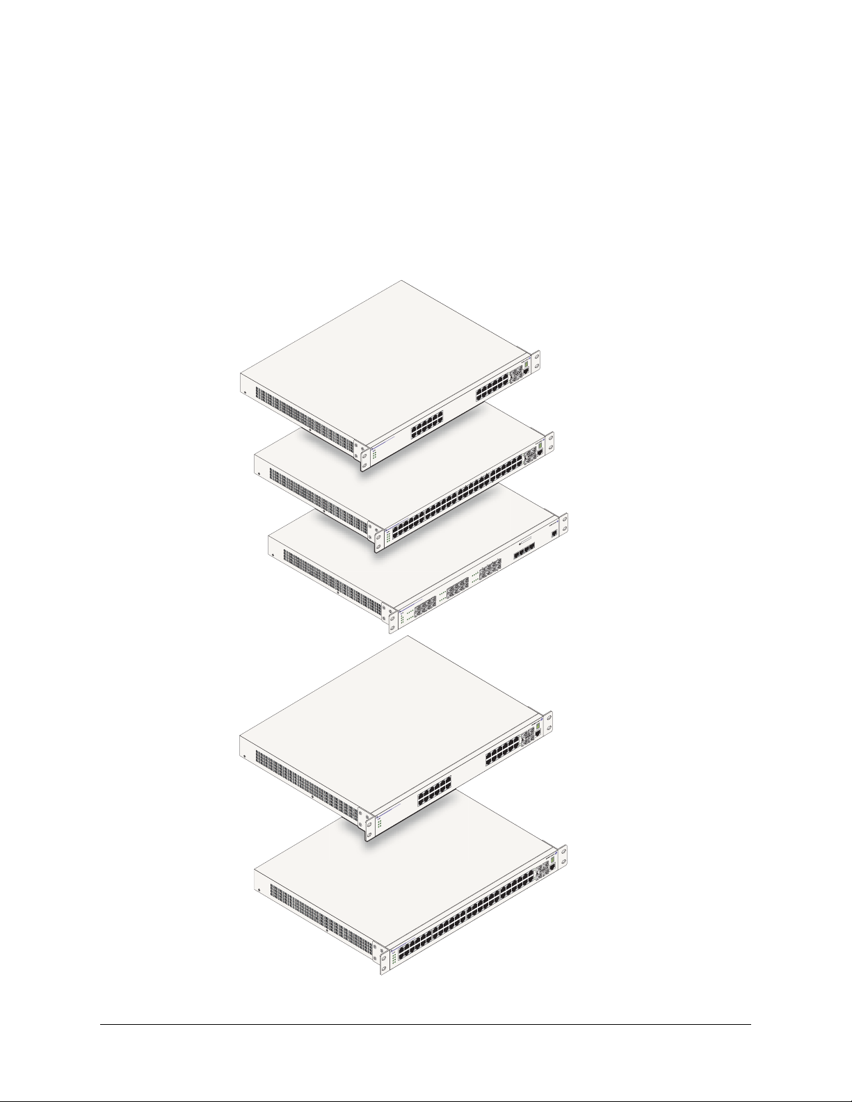
The OmniSwitch 6800 Series is an advanced fixed configuration family of Ethernet switches. These
switches provide wire rate layer-2 forwarding and layer-3 routing with advanced services.
23
21
21
23 LINK/ACT
23
Console
21
24
19
22
17
22
24
15
24 LINK/ACT
22
13
20
18
16
14
11
9
7
5
12
3
10
Speed 1
8
6
4
Speed 2
24
OmniSwitch 6800-
PRI
BPS
OK
TMP
PWR
FAN
32
23
30
21
28
19
26
17
24
15
22
13
20
11
18
9
16
7
5
14
3
12
48
10
Speed 1
OmniSwitch 6800-
8
6
PRI
4
BPS
OK
TMP
PWR
Speed 2
XFP2
FAN
XFP1
3
2
21
19
17
15
18
24
13
22
20
18
11
9
16
15
13
14
11
9
12
7
10
5
14 16
12
3
10
4
1
8
7
5
OmniSwitch 6800-U2
6
3
1
4
2
BPS
OK
68
PWR
4
2
FAN TMP
XFP1 XFP2
45
45
47 LINK/ACT
47
45
43
46
41
46
48
39
48 LINK/ACT
46
44
42
40
CLASS 1 LASER PRODUCT
23
22
21
Speed
22
20
OmniSwitch 6800-24
47
Console
48
OmniSwitch 6800-48
Console
24
LNK/ACT
OmniSwitch 6800-U24
3
2
1
2
1
2
T
C
A
/
K
N
I
L
3
2
3
2
Console
1
2
4
2
9
1
2
2
7
1
2
4
2
2
T
C
A
/
K
N
I
5
L
1
4
2
2
3
2
1
0
2
8
1
6
1
4
1
1
1
9
7
5
2
1
3
0
1
1
d
e
e
p
S
8
6
4
2
d
e
e
p
S
24L
OmniSwitch 6800-
I
R
P
S
P
K
B
O
P
M
T
R
W
P
N
A
F
3
4
1
4
9
3
7
3
4
4
5
3
2
4
3
3
0
4
1
3
8
3
9
2
6
7
3
2
4
5
3
2
2
3
3
2
0
3
1
2
8
2
9
1
6
2
7
1
4
5
2
1
2
2
3
1
0
2
1
1
8
1
9
6
1
7
4
1
5
2
3
1
48L
0
1
1
d
e
e
p
S
OmniSwitch 6800-
8
6
I
R
P
S
P
4
K
B
O
P
M
T
R
W
P
2
d
e
2
e
P
p
F
S
X
N
A
F
1
P
F
X
OmniSwitch 6800-24L
7
4
5
4
5
4
T
C
A
/
K
N
I
L
7
4
7
4
Console
5
4
8
4
6
4
6
8
4
4
T
C
A
/
K
N
I
L
8
4
6
4
OmniSwitch 6800-48L
OmniSwitch 6800 Series Hardware Users Guide June 2007 page 1-1
Page 16

OmniSwitch 6800 Series
• The OmniSwitch 6800-24 (OS6800-24) is a 24 port, 10/100/1000 fixed stackable chassis.
• The OmniSwitch 6800-48 (OS6800-48) is a 48 port, 10/100/1000 fixed stackable chassis. This switch
also supports a 10 Gigabit uplink module.
• The OmniSwitch 6800-U24 (OS6800-U24) is a 24 fiber 1000 Mbps SFP connector chassis. This switch
also supports a 10 Gigabit uplink module.
• The OmniSwitch 6800-24L (OS6800-24L) is a 24 port fixed stackable chassis. This chassis has 20
unshared 10/100 ports, which can be upgraded to 10/100/1000 ports.
• The OmniSwitch 6800-48L (OS6800-48L) is a 48 port fixed stackable chassis. This chassis has 44
unshared 10/100 ports, which can be upgraded to 10/100/1000 ports.
Whether operating as a single switch or as a stack, the OmniSwitch 6800 Series offers effective
availability, resiliency, and security features and are ideal for the following network applications:
• Enterprise workgroups/LAN wiring closets
• Edge deployments and branch offices
• L3 aggregation/distribution layer switches in three-tier networks
• Small enterprise core switching
• Quality of service (QoS) for mission critical applications
• Data center server clusters
Note on Terminology. In the user guides provided with your OmniSwitch 6800 Series switch, the terms
stack and virtual chassis are interchangeable terms referring to OmniSwitch 6800 Series switches in a
stacked configuration. The terms module, switch, slot and element are used to refer to individual switches
within a stacked configuration. The terms Chassis Management Module (CMM) and management module
refer to those switches operating in a stack either in primary or secondary management roles. OmniSwitch
6800 Series switches operating in an idle role are essentially acting as network interface modules and
therefore may be referred to as Network Interfaces (NIs).
page 1-2 OmniSwitch 6800 Series Hardware Users Guide June 2007
Page 17
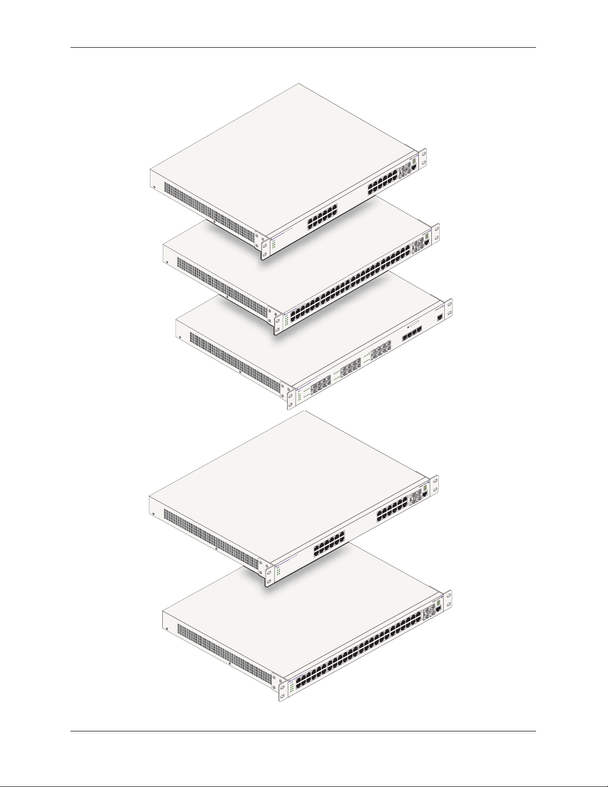
OmniSwitch 6800 Series Stacked Configurations
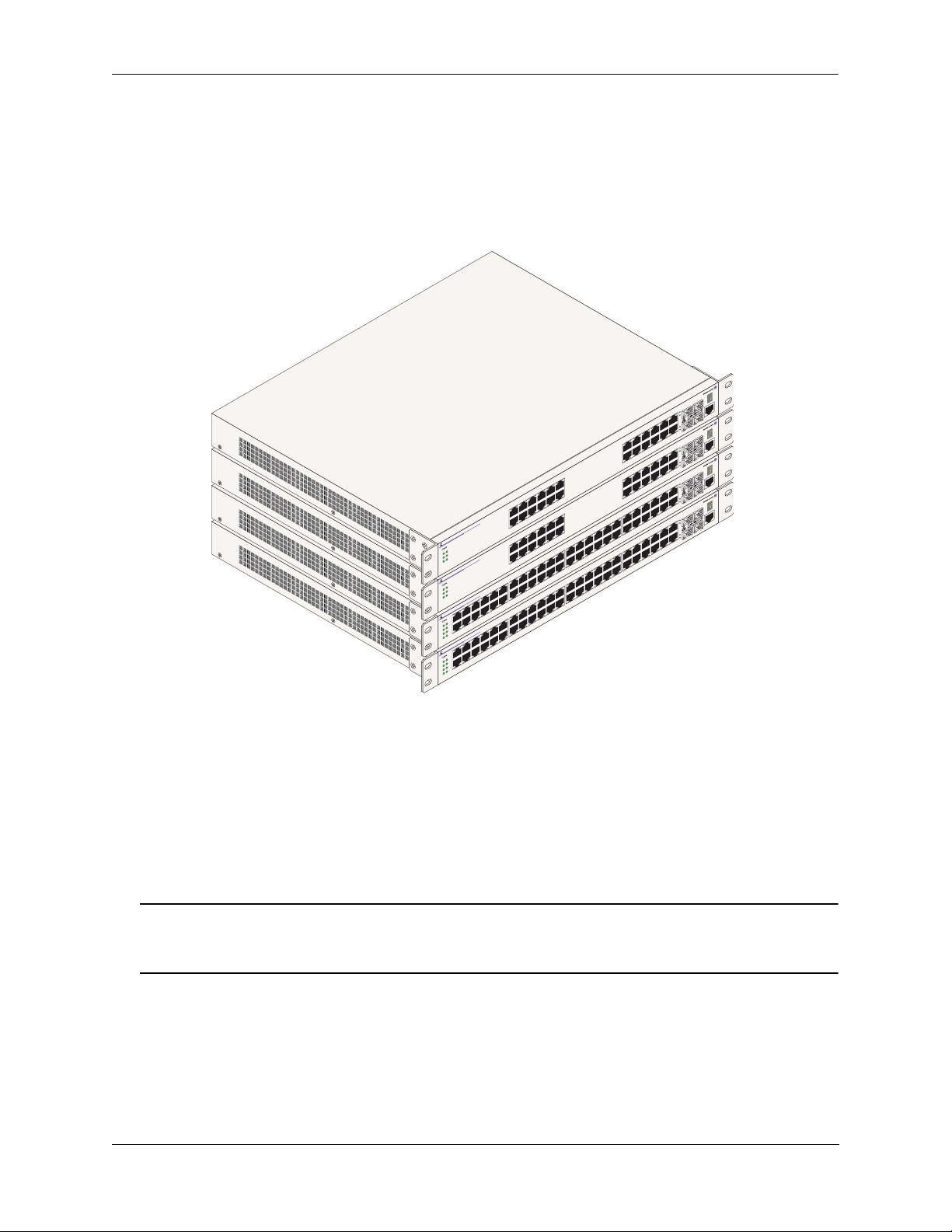
Stacked Configurations
In addition to working as individual, stand-alone switches, OmniSwitch 6800 Series switches (except for
the OS6800-U24) can also be linked together to form a single, high-density virtual chassis known as a
stack.
3
2
1
2
21
T
C
/A
K
N
I
3 L
2
le
o
s
23
n
o
C
1
2
4
2
9
1
22
7
1
22
24
T
C
/A
K
IN
5
L
1
4
2
3
2
2
3
2
O
W
P
A
F
O
W
P
A
F
O
W
P
A
F
P
F
X
P
A
F
P
F
X
OmniSwitch 6800-24
K
R
NT
OmniSwitch 6800
K
R
NT
OmniSwitch 6800-48
K
R
N
1
OmniSwitch 6800-48
K
O
R
W
N
1
1
6
1
4
1
5
1
3
1
1
9
7
5
2
1
3
0
1
1
d
e
e
p
S
8
1
1
6
9
4
7
2
d
e
e
p
S
5
2
1
3
1
d
e
e
p
I
PR
S
P
B
P
M
-24
I
R
P
S
P
B
P
M
1
d
e
e
p
S
I
R
P
S
P
B
P
M
T
2
d
e
2
e
P
p
F
S
X
1
d
e
e
p
S
I
R
P
S
P
B
P
M
T
2
d
e
2
e
P
p
F
S
X
S
6
4
2
d
e
e
p
S
7
1
5
1
3
1
1
1
8
1
9
6
1
7
4
1
5
3
8
6
4
7
5
3
8
6
4
7
1
2
1
5
1
0
1
3
1
1
1
8
1
9
6
1
4
1
2
1
0
1
2
0
1
5
2
8
3
2
1
2
9
1
6
2
4
2
2
2
2
5
2
0
2
3
2
1
2
9
1
6
2
4
2
2
2
0
2
1
6
1
4
1
9
3
7
3
5
3
3
3
0
4
1
3
8
3
9
2
6
7
3
9
3
4
3
7
3
2
3
5
3
0
3
3
3
8
2
9
2
7
0
3
8
2
0
4
1
3
8
3
6
3
4
3
2
3
1
2
0
2
21
T
C
/A
K
IN
L
3
2
8
1
9
1
7
1
0
2
8
1
3
4
1
4
4
4
2
4
3
4
1
4
4
4
2
4
le
so
23
n
o
C
1
2
4
2
22
2
4
2
2
T
C
/A
K
IN
L
4
2
7
4
2
2
5
4
45
T
AC
/
K
N
I
L
7
4
le
so
46
n
o
C
5
4
8
4
47
6
4
48
T
C
/A
K
N
I
L
8
4
7
4
6
4
5
4
45
T
C
/A
K
N
I
L
7
4
le
o
s
46
n
o
C
5
4
8
4
47
6
4
48
T
C
/A
K
IN
L
8
4
6
4
OmniSwitch 6800 Series Stacked Configuration (Stack of Four Shown)
Stacking switches provides scalability by allowing users to quickly and easily expand 10/100/1000 port
density. Twenty-four 10/100/1000 ports are added for each OS6800-24 brought into the stack and
forty-eight 10/100/1000 ports are added for each OS6800-48.
Up to eight switches can be stacked. OmniSwitch 6800 Series switches can be mixed and matched in any
combination within the stack. This provides a virtual chassis with a 10/100/1000 capacity of up to 384
ports.
Note. Other stackable Alcatel-Lucent products, such as the OmniSwitch 6600 Series switch, cannot be
added to an OmniSwitch 6800 Series virtual chassis. For comprehensive information on managing stacked
configurations, refer to Chapter 3, “Managing OmniSwitch 6800 Series Stacks.”
OmniSwitch 6800 Series Hardware Users Guide June 2007 page 1-3
Page 18

Availability Features OmniSwitch 6800 Series
Availability Features
The switch provides a broad variety of availability features. Availability features are hardware and
software-based safeguards that help prevent the loss of data flow in the unlikely event of a subsystem
failure. In addition, some availability features allow users to maintain or replace hardware components
without powering off the switch or interrupting switch operations. Combined, these features provide added
resiliency and help ensure that the switch or virtual chassis is consistently available for day-to-day network
operations.
Hardware-related Availability features include:
• Management Module Redundancy
• Software Rollback
• Backup Power Supplies
• Hot Swapping
• Hardware Monitoring
Management Module Redundancy
In stacked configurations, one OmniSwitch 6800 Series switch is designated as the primary “management
module” for the stack. Because the stack can be thought of as a virtual chassis, the role of this primary
management switch is to monitor and manage the functions of the stack.
Similar to chassis-based switches, such as the OmniSwitch 9700 and Omniswitch 9800, the stack also
allows users to assign an additional switch as a secondary management module. As with the OS9700 and
OS9800, the stack’s secondary switch immediately takes over management functions in the event of a
primary switch failure.
All other switches in the stack are considered idle, and act very much like Network Interface (NI)
modules, in that they provide Ethernet ports for 10/100/1000 traffic.
The stack provides support for all idle switches during primary-to-secondary failover. In other words, if
the stack’s primary switch fails or goes offline for any reason, all idle switches will continue data
transmission during the secondary switch’s takeover process.
Incoming Layer 2 packets will continue to be sent to the appropriate egress port during failover. Spanning
Tree will continue handling BPDUs received on the switch ports, as well as port link up and down states.
The Spanning Tree topology will not be disrupted.
Note. For detailed information on primary, secondary, and idle switches, as well as the failover process,
refer to Chapter 3, “Managing OmniSwitch 6800 Series Stacks.”
page 1-4 OmniSwitch 6800 Series Hardware Users Guide June 2007
Page 19

OmniSwitch 6800 Series Availability Features
Software Rollback
Software rollback (also referred to as image rollback) essentially allows the OmniSwitch 6800 Series
switches (in both standalone and stacked configurations) to return to a prior “last known good” version of
software in the event of a system software problem. The switch controls software rollback through its
resilient directory structure design (i.e., /flash/working and /flash/certified).
For detailed information on the software rollback feature, as well as the switch’s /flash/working and
/flash/certified directories, refer to the “Managing CMM Directory Content” chapter in the OmniSwitch
6800/6850/9000 Switch Management Guide.
Backup Power Supplies
OmniSwitch 6800 Series switches support an optional backup power supply shelf. The backup power
supply shelf is a separate, rack-mountable chassis offering power supply bays for up to eight 225 watt
power supply modules. This provides redundant chassis power on a 1:1 basis.
Backup power supplies operate in active standby mode. If the primary power supply fails unexpectedly,
the backup power supply automatically takes up the full power load without disrupting the switch.
Note. For more information on backup power supplies, refer to Chapter 2, “OmniSwitch 6800 Series
Chassis and Hardware Components.”
Hot Swapping
Hot swapping refers to the action of adding, removing, or replacing components without powering off
switches or disrupting other components in the switch or stack. This feature facilitates hardware upgrades
and maintenance and allows users to easily replace components in the unlikely event of hardware failure.
The following hardware components can be hot swapped:
• OS6800-BPS-225 backup power supplies
• Backup power supply connector cables
• Backup power supply daughtercard module
• SFPs
• Modules operating in idle status within a stacked configuration (see Chapter 3, “Managing
OmniSwitch 6800 Series Stacks.”)
• Stacking cables (see note below)
Note. Stacking cables can be hot swapped as long as the stack is not split into two or more separate stacks
in the process. In addition, a redundant cable connection must always be in place before swapping
stacking cables. Otherwise, stack operations may be disrupted. For information on stacking cables, refer to
Chapter 2, “OmniSwitch 6800 Series Chassis and Hardware Components.”
For instructions on hot swapping backup power supplies, refer to Chapter 2, “OmniSwitch 6800 Series
Chassis and Hardware Components.” For instructions on hot swapping combo port SFPs, refer to the
instruction card provided with the SFP product. For instructions on hot swapping modules within a
stacked configuration, refer to Chapter 3, “Managing OmniSwitch 6800 Series Stacks.”
OmniSwitch 6800 Series Hardware Users Guide June 2007 page 1-5
Page 20

Availability Features OmniSwitch 6800 Series
Hardware Monitoring
Automatic Monitoring
Automatic monitoring refers to the switch’s built-in sensors that automatically monitor operations. If an
error is detected (e.g., over-threshold temperature), the switch immediately sends a trap to the user. The
trap is displayed on the console in the form of a text error message. (In the case of an over-threshold
temperature condition, the chassis displays an amber TMP LED in addition to sending a trap.)
LEDs
LEDs, which provide visual status information, are provided on the chassis front panel. LEDs are used to
indicate conditions such as hardware and software status, temperature errors, link integrity, data flow, etc.
For detailed LED descriptions, refer to Chapter 2, “OmniSwitch 6800 Series Chassis and Hardware
Components.”
User-Driven Monitoring
User-driven hardware monitoring refers to CLI commands that are entered by the user in order to access
the current status of hardware components. The user enters “show” commands that output information to
the console. Monitoring information for chassis components such as the optional back up power supply,
chassis temperature sensor, and chassis fans is provided in Chapter 2, “OmniSwitch 6800 Series Chassis
and Hardware Components.” Show commands for all features are described in detail in the OmniSwitch
CLI Reference Guide.
page 1-6 OmniSwitch 6800 Series Hardware Users Guide June 2007
Page 21

OmniSwitch 6800 Series Port and Fabric Capacities
Port and Fabric Capacities
OmniSwitch 6800 Series switches offer 20 non combo 10/100/1000 Ethernet ports, 44 non combo
10/100/1000 Ethernet ports, 20 non combo 1000 Mbps SFP connectors, 20 non combo 10/100 Ethernet
ports, or 44 non combo 10/100 Ethernet ports. The switches also offer combo ports, which consist of four
paired Gigabit Ethernet SFP connectors and four 10/100/100 Ethernet ports.
OmniSwitch 6800 Series Switching Fabric Capacity
OmniSwitch 6800-24 160 Gbps aggregate
OmniSwitch 6800-48 160 Gbps aggregate
OmniSwitch 6800-U24 80 Gbps
OmniSwitch 6800-24L 160 Gbps aggregate
OmniSwitch 6800-48L 160 Gbps aggregate
OmniSwitch 6800 Series Performance Specifications
Stacking capacity 40 Gbps
Jumbo frames Up to 9 KB
MAC addresses 16 K
For detailed information on OmniSwitch 6800 Series features, functions, and technical specifications,
refer to Chapter 2, “OmniSwitch 6800 Series Chassis and Hardware Components” and Chapter 3,
“Managing OmniSwitch 6800 Series Stacks.”
OmniSwitch 6800 Series Hardware Users Guide June 2007 page 1-7
Page 22
OmniSwitch 6800 Series Application Examples OmniSwitch 6800 Series
OmniSwitch 6800 Series Application Examples
The following OmniSwitch 6800 Series applications are described below:
• Gigabit-to-the-desktop migration
• Server aggregation
• Layer 3 Aggregation/Distribution
• Small Enterprise core
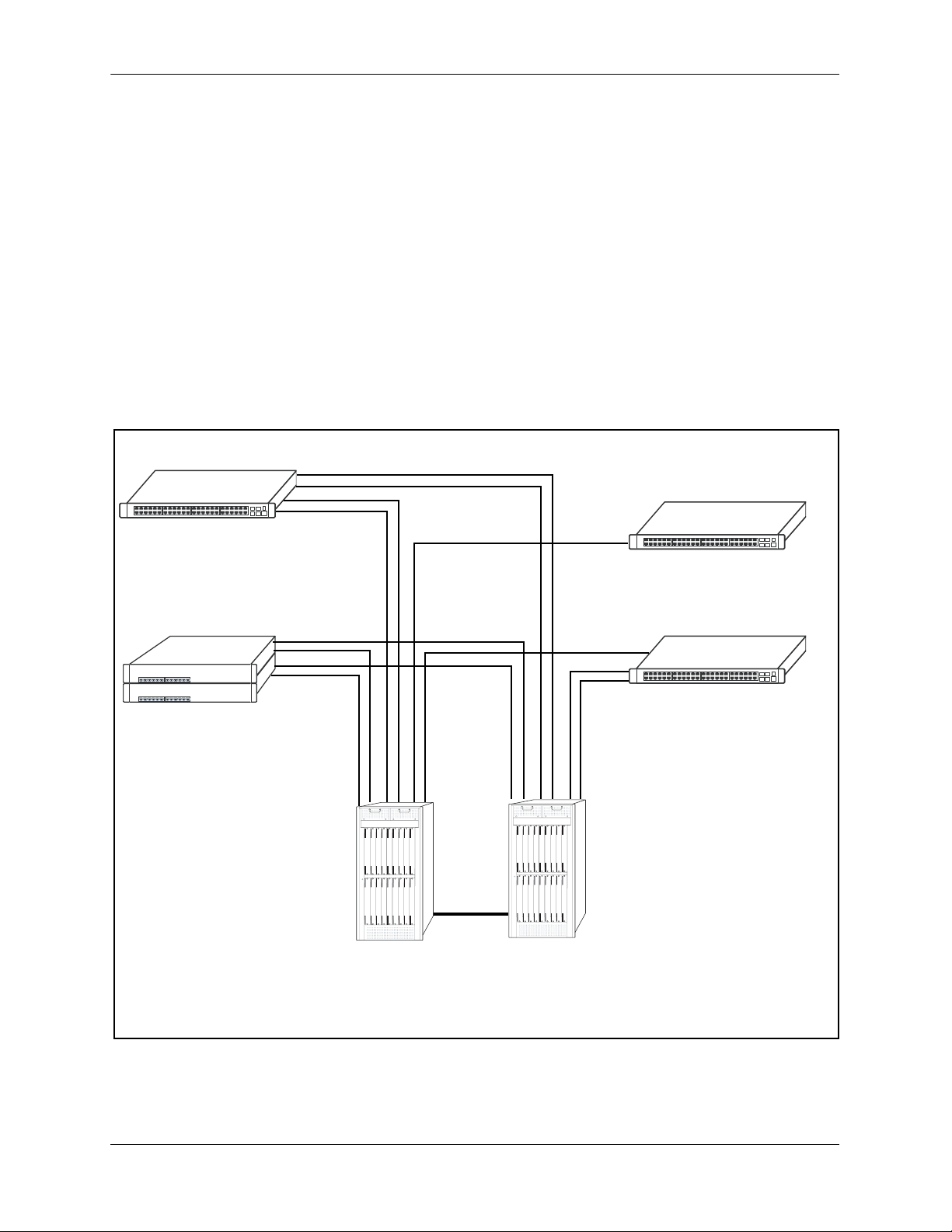
Gigabit-to-the-Desktop Migration
OmniSwitch 6800 Series switches provide a migration path to Gigabit on the edge of the LAN.
For example:
10/100/1000 Layer 2+ Switching
10/100/1000 Layer 3 Switching
OmniSwitch 6800
Layer 2+ 10/100 Switching
OmniSwitch 6800
OmniSwitch 6800
Core Layer
Application Example: Gigabit-to-the-Desktop Migration
page 1-8 OmniSwitch 6800 Series Hardware Users Guide June 2007
Page 23
OmniSwitch 6800 Series OmniSwitch 6800 Series Application Examples
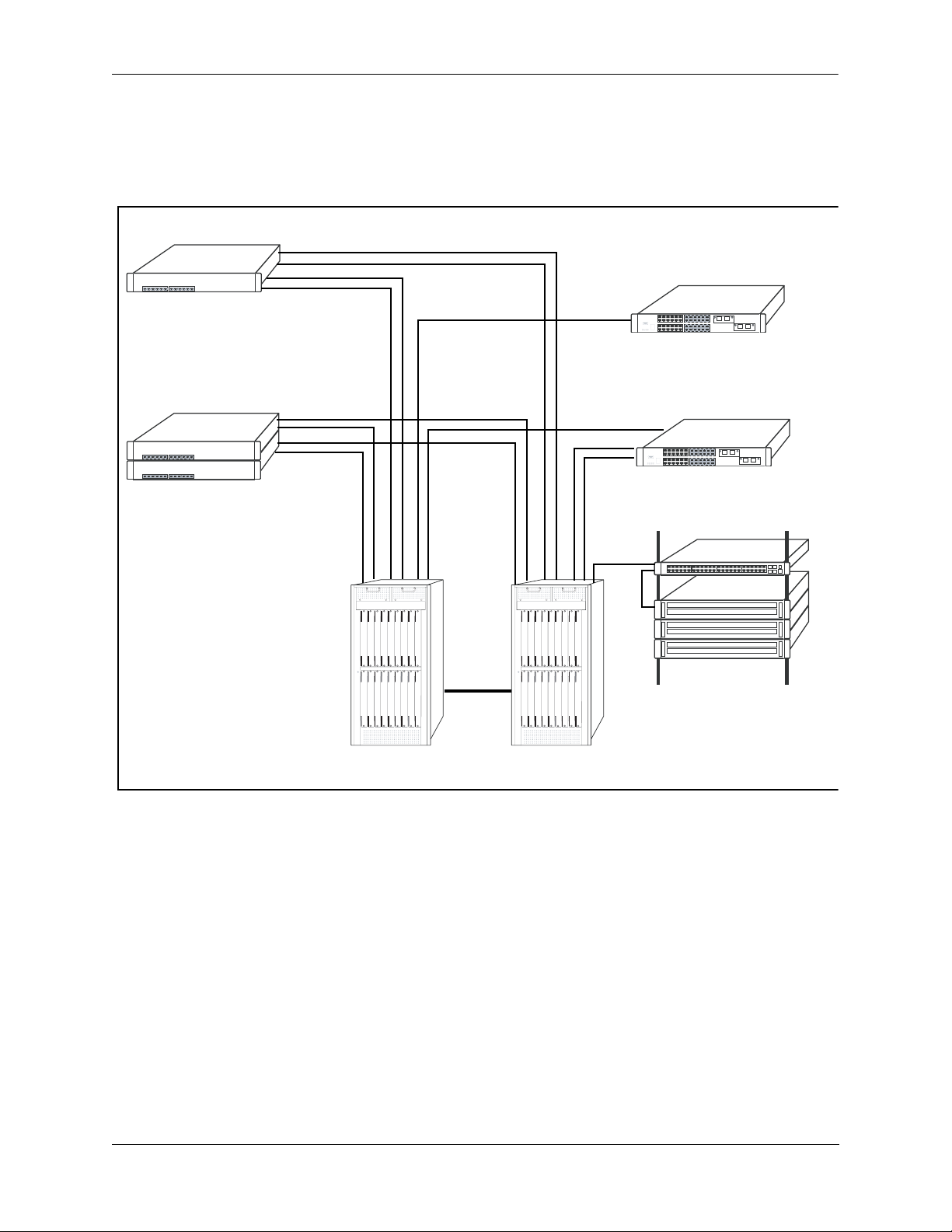
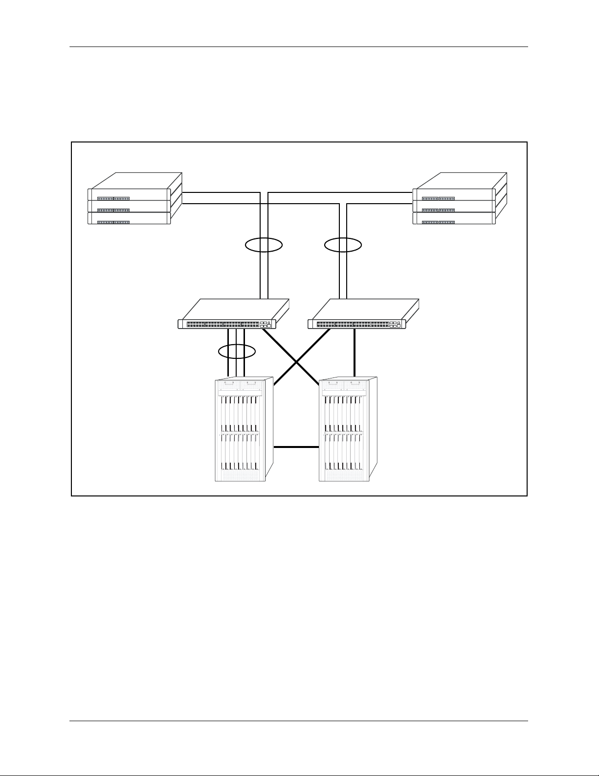
Server Aggregation
The OmniSwitch 6800 Series switch is a well-suited server aggregation switch, especially for spaceconstrained data centers, where the switch can be installed in the same rack as the servers. For example:
10/100/1000 Switching
10/100/1000 Switching
Application Example: Server Aggregation
OmniSwitch 6800
Servers
OmniSwitch 6800 Series Hardware Users Guide June 2007 page 1-9
Page 24
OmniSwitch 6800 Series Application Examples OmniSwitch 6800 Series
Layer 3 Aggregation/Distribution
OmniSwitch 6800 Series switches placed in the distribution layer of three-tier networks provide highcapacity, wire speed Layer 2 switching, Layer 3 routing, and intelligent services near the edge of the
network. For example:
10/100 Switching
Gigabit
Uplinks
OmniSwitch 6800
Aggregation Layer
(L2/L3 Switching)
OmniSwitch 6800
Multiple
1 Gig
10 Gig
10 Gig
10 Gig
Core Layer
(L3)
Application Example: Layer 3 Aggregation/Distribution
page 1-10 OmniSwitch 6800 Series Hardware Users Guide June 2007
Page 25
OmniSwitch 6800 Series OmniSwitch 6800 Series Application Examples
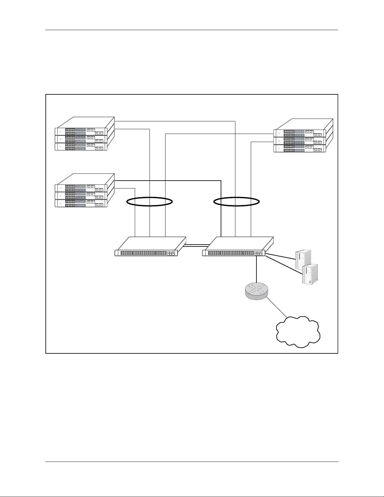
Small Enterprise Core
With its high-speed switching capacity, supported Layer 3 routing protocols, advanced network services,
and wire speed 10 Gigabit capability, the OmniSwitch 6800 Series provides effective core switching for
smaller Enterprise networks (200-500 ports). For example:
10/100 layer 2 Switching
10/100 layer 2 Switching
OmniSwitch 6800
Series Switch
Gigabit Layer 3 Switching
Gigabit Uplinks
OmniSwitch 6800
Series Switch
Internet
Router
10/100 layer 2 Switching
Servers
Internet
Application Example: Small Enterprise Core
OmniSwitch 6800 Series Hardware Users Guide June 2007 page 1-11
Page 26

OmniSwitch 6800 Series Application Examples OmniSwitch 6800 Series
page 1-12 OmniSwitch 6800 Series Hardware Users Guide June 2007
Page 27

2 OmniSwitch 6800 Series
Chassis and Hardware
Components
OmniSwitch 6800 Series switches are available in five stackable chassis configurations—the 24-port
OmniSwitch 6800-24 (OS6800-24), OmniSwitch 6800-U24 (OS6800-U24), OmniSwitch 6800-24L
(OS6800-24L), the 48-port OmniSwitch 6800-48 (OS6800-48), and OmniSwitch 6800-48L (OS680048L). This chapter includes detailed information on these chassis types. Topics include:
• OmniSwitch 6800 Series chassis descriptions
• Technical specifications
• Mounting the switch
• Setting up a stacked configuration
• Booting OmniSwitch 6800 Series switches
• Monitoring the chassis
• Backup power supply components
• Monitoring backup power supply status
• Pinouts, power cord, and console port specifications
OmniSwitch 6800 Series Hardware Users Guide June 2007 page 2-1
Page 28
OmniSwitch 6800 Series Chassis and Hardware Components
OmniSwitch 6800-24
23
21
21
CT
23 LINK/A
23
Console
21
24
19
22
17
22
24
15
24 LINK/ACT
22
13
20
18
16
11
9
7
5
12
3
10
Speed 1
8
6
4
Speed 2
24
OmniSwitch 6800-
PRI
BPS
OK
TMP
PWR
FAN
19
17
15
13
20
11
18
9
16
7
5
14
3
12
48
10
Speed 1
OmniSwitch 6800-
8
6
PRI
4
BPS
OK
TMP
PWR
Speed 2
XFP2
FAN
XFP1
15
13
11
9
7
5
14 16
12
3
10
4
1
8
7
5
OmniSwitch 6800-U2
6
3
1
4
2
BPS
OK
68
PWR
4
2
FAN TMP
XFP1 XFP2
14
OmniSwitch 6800-48
47
45
5
4
CT
47 LINK/A
47
Console
45
48
43
46
41
46
48
39
48 LINK/ACT
46
44
42
40
32
23
30
21
28
26
24
22
3
2
21
19
17
15
24
13
22
20
18
11
9
16
14
12
10
Speed
22
20
18
OmniSwitch 6800-U24
Console
24
CLASS 1 LASER PRODUCT
23
22
LNK/ACT
21
OmniSwitch 6800-24L
3
2
1
2
1
2
T
C
A
/
K
N
I
L
3
2
le
3
so
2
n
o
C
1
2
4
2
9
1
2
2
7
1
2
4
2
2
T
C
A
/
K
N
I
5
L
1
4
2
2
3
2
1
0
2
8
1
6
1
4
1
1
9
7
5
2
1
3
0
1
1
d
e
e
p
S
8
6
4
2
d
e
e
p
S
L
4
2
0
0
8
6
h
itc
iSw
n
m
O
I
R
P
S
P
K
B
O
P
M
T
R
W
P
N
A
F
9
1
7
1
5
1
3
1
0
2
1
1
8
1
9
6
1
7
4
1
5
2
3
1
L
8
4
-
0
0
8
6
0
h
1
1
itc
d
e
e
w
p
S
iS
n
m
O
8
6
I
R
P
S
P
4
K
B
O
P
M
T
R
W
P
2
d
e
2
e
P
p
F
S
X
N
A
F
1
P
F
X
1
OmniSwitch 6800-48L
7
4
5
4
45
T
C
/A
K
N
I
L
7
4
le
so
47
on
C
5
4
8
4
3
4
46
1
4
6
4
48
T
C
A
/
K
N
I
9
L
3
8
4
6
7
4
3
4
4
5
3
2
4
3
3
0
4
1
3
8
3
9
2
6
7
3
2
4
5
3
2
2
3
3
2
0
3
1
2
8
2
6
2
4
2
2
2
page 2-2 OmniSwitch 6800 Series Hardware Users Guide June 2007
Page 29
OmniSwitch 6800 Series Chassis and Hardware Components OmniSwitch 6800-24
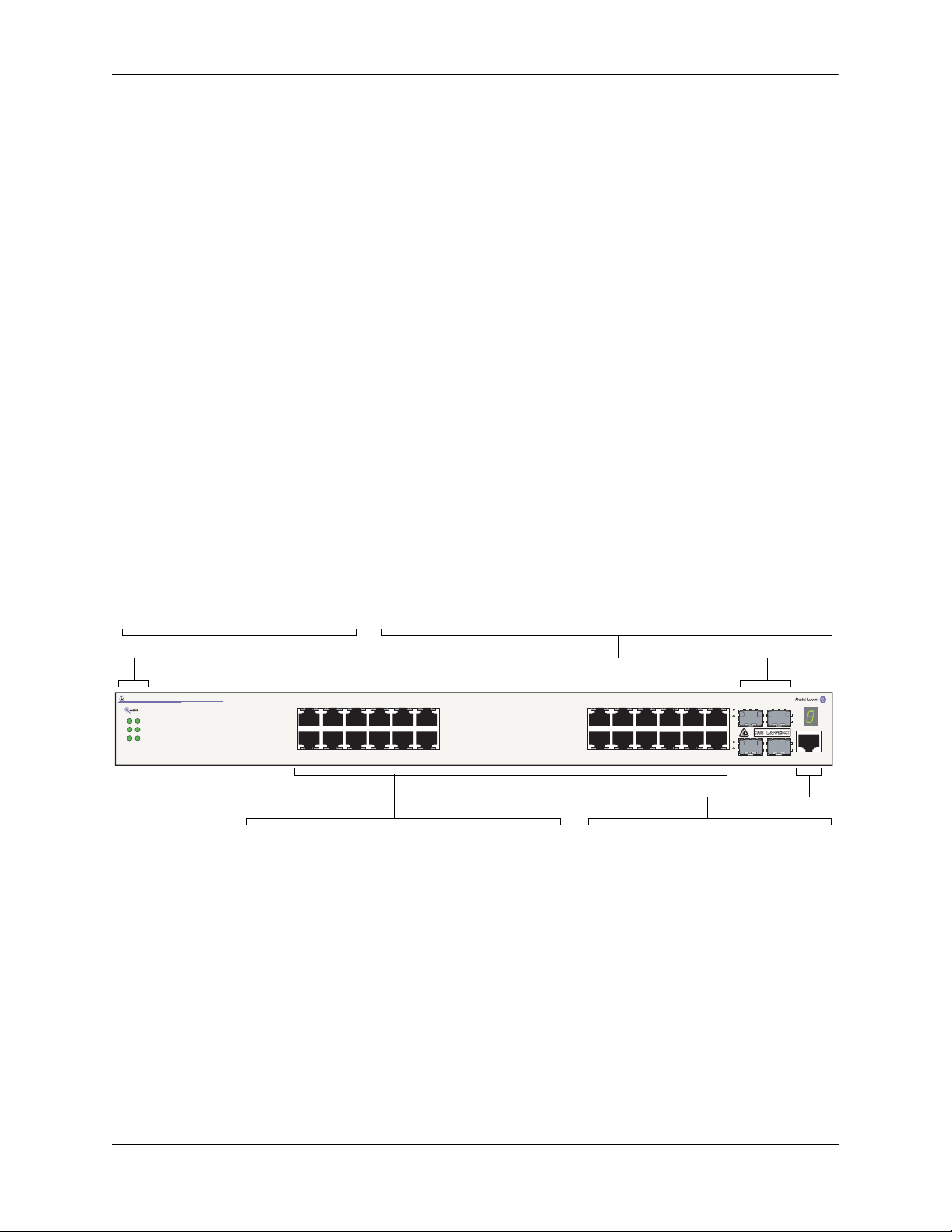
OmniSwitch 6800-24
The OmniSwitch 6800-24 is a stackable edge/workgroup switch offering 24 10/100/1000Base-T ports, as
well as four combo SFP connectors for high speed connections.
The front panel of the OS6800-24 chassis contains the following major components:
• System status and slot indicator LEDs
• (24) 10/100/1000Base-T ports
• (4) Combo SFP connectors for 1000Base-X connections
• Console port (RJ-45)
Refer to the illustration below for more front panel information. For detailed LED descriptions, refer to
page 2-13. For information on the chassis rear panel, refer to page 2-15.
Combo SFP Connectors
The OS6800-24 provides four combo SFP connectors for 1000Base-X highspeed connections.
System Status LEDs
For detailed information on OS6800-24
system status and other LEDs, refer to
page 2-13.
OmniSwitch 6800-24
OK
PWR
FAN TMP
PRI
BPS
Speed 1
10/100/1000Mbps Ports
The OS6800-24 provides 20 fixed 10/100/1000BaseT
non combo ports (1–20) and 4 fixed 10/100/1000BaseT
combo ports (21–24). These ports are auto-sensing and
auto-MDIX and use RJ-45 connectors.
3
567891011
4Speed 2
By default, when an SFP is installed in a combo port, it takes over the port
number of the corresponding RJ-45 Ethernet port. In other words, if an SFP is
installed in the slot labeled 24, Ethernet port 24 is no longer available and cannot be used for 10/100/1000 traffic. This default setting is referred to as
“preferred fiber.” Refer to “Configuring Ethernet Ports” in the Network
Configuration Guide for detailed information, including steps for configuring
combo port settings.
151617181920212223 LINK/ACT
13
12
14
24 LINK/ACT
21
23
22
24
21 23
22 24
Console
Console Port
The OS6800-24 front panel provides one
RJ-45 port for console connections. Console connections are used by network
administrators for switch management.
This female RJ-45 connector provides a
DTE console connection.
OmniSwitch 6800-24 Front Panel
OmniSwitch 6800 Series Hardware Users Guide June 2007 page 2-3
Page 30

OmniSwitch 6800-24 OmniSwitch 6800 Series Chassis and Hardware Components
OS6800-24 Specifications
Total 10/100/1000Base-T ports
24
per switch
Total combo SFP connectors per
4
switch
Total 10/100/1000Base-T ports
192 (stack of eight switches)
per stack
Total combo SFP connectors per
32 (stack of eight switches)
stack
Fabric capacity 160 Gbps
Power 150W AC/DC power supply, providing +12V @ 12.5A;
90-264VAC50-60 Hz universal input
Total available power supplies 2 (one factory-installed power supply and
one optional backup power supply)
Flash memory size 64 MB
RAM memory size 256 MB SDRAM
Overall Width (rack-mount
19 inches, approx.
flanges included)
Chassis Width (rack-mount
17.32 inches
flanges not included)
Height 1.73 inches
Height (rack units) 1 RU
Chassis Depth 16.73 inches
Weight 13.88 lbs. (6.30 Kg)
Humidity 5% to 90% Relative Humidity (Operating)
0% to 95% Relative Humidity (Storage)
Operating Temperature 0 to 45 degrees, Celsius
Storage Temperature -20 to 70 degrees, Celsius
Altitude Operating altitude: sea level at 40 degrees, Celsius and
10000 feet at 0 degrees, Celsius
Storage altitude: sea level at 40000 feet
page 2-4 OmniSwitch 6800 Series Hardware Users Guide June 2007
Page 31

OmniSwitch 6800 Series Chassis and Hardware Components OmniSwitch 6800-48
OmniSwitch 6800-48
The OmniSwitch 6800-48 is a stackable edge/workgroup switch offering 48 10/100/1000Base-T ports, as
well as four combo SFP connectors for high speed connections.
The front panel of the OS6800-48 chassis contains the following major components:
• System status and slot indicator LEDs
• (48) 10/100/1000Base-T ports
• (4) Combo SFP connectors for 1000Base-X connections
• Console port (RJ-45)
An Optional 10 Gigabit module is also supported (see page 2-34).
Refer to the illustration below for more front panel information. For detailed LED descriptions, refer to
page 2-13. For information on the chassis rear panel, refer to page 2-15.
Combo SFP Connectors
The OS6800-48 provides four combo SFP connectors for 1000Base-X highspeed connections.
Status and Slot Indicator LEDs
For detailed information on OS6800-48
status and slot indicator LEDs, refer to
page 2-13.
OmniSwitch 6800-48
OK
PWR
FAN
XFP1 XFP2
Speed 1
PRI
BPS
TMP
Speed 2
34567891011
13
12
10/100/1000Mbps Ports
The OS6800-48 provides 44 fixed 10/100/1000BaseT
ports (1–44) and 4 fixed 10/100/1000BaseT combo
ports (45–48). These ports are auto-sensing and autoMDIX and use RJ-45 connectors.
15
17181920212223
1614
By default, when an SFP is installed in a combo port, it takes over the port
number of the corresponding RJ-45 Ethernet port. In other words, if an SFP is
installed in the slot labeled 45, Ethernet port 45 is no longer available and
cannot be used for 10/100/1000 traffic. This default setting is referred to as
“preferred fiber.” Refer to “Configuring Ethernet Ports” in the Network Con-
figuration Guide for detailed information, including steps for configuring
combo port settings.
272829303132333435
25
24
26
36
394041424344454647 LINK/ACT
37
38
48 LINK/ACT
45
47
46
48
45 47
46 48
Console
Console Port
The OS6800-48 front panel provides one
RJ-45 port for console connections. Console connections are used by network
administrators for switch management.
This female RJ-45 connector provides a
DTE console connection.
OmniSwitch 6800-48 Front Panel
OmniSwitch 6800 Series Hardware Users Guide June 2007 page 2-5
Page 32

OmniSwitch 6800-48 OmniSwitch 6800 Series Chassis and Hardware Components
OS6800-48 Specifications
Total 10/100/1000Base-T ports
48
per switch
Total combo SFP connectors per
4
switch
Total 10/100/1000Base-T ports
384 (stack of eight switches)
per stack
Total combo SFP connectors per
32 (stack of eight switches)
stack
Fabric capacity 160 Gbps
Power 150W AC/DC power supply, providing +12V @ 12.5A;
90-264VAC50-60 Hz universal input
Total available power supplies 2 (one factory-installed power supply and
one optional backup power supply)
Flash memory size 64 MB
RAM memory size 256 MB SDRAM
Overall Width (rack-mount
19 inches, approx.
flanges included)
Chassis Width (rack-mount
17.32 inches
flanges not included)
Height 1.73 inches
Height (rack units) 1 RU
Chassis Depth 16.73 inches
Weight 14.41 lbs. (6.54 Kg)
Humidity 5% to 90% Relative Humidity (Operating)
0% to 95% Relative Humidity (Storage)
Operating Temperature 0 to 45 degrees, Celsius
Storage Temperature -20 to 70 degrees, Celsius
Altitude Operating altitude: sea level at 40 degrees, Celsius and
10000 feet at 0 degrees, Celsius
Storage altitude: sea level at 40000 feet
page 2-6 OmniSwitch 6800 Series Hardware Users Guide June 2007
Page 33

OmniSwitch 6800 Series Chassis and Hardware Components OmniSwitch 6800-U24
OmniSwitch 6800-U24
The OmniSwitch 6800-U24 is an edge/workgroup switch offering 24 1000Base-X SFP connectors, as well
as four combo 10/100/1000Base-T ports.
The front panel of the OS6800-U24 chassis contains the following major components:
• System status and slot indicator LEDs
• (24) 1000Base-X SFP connectors
• (4) Combo RJ-45 10/100/1000Base-T ports
• Console port (RJ-45)
An Optional 10 Gigabit module is also supported (see page 2-15).
Note. The OmniSwitch 6800-U24 operates in stand-alone mode only. It does not support stacking.
Refer to the illustration below for more front panel information. For detailed LED descriptions, refer to
page 2-13. For information on the chassis rear panel, refer to page 2-15.
Combo RJ-45 10/100/1000 Ports
The OS6800-U24 provides four combo 10/100/1000BaseT ports. These
ports are auto-sensing and auto-MDIX and use RJ-45 connectors.
System Status LEDs
For detailed information on OS6800-U24
system status and other LEDs, refer to page
2-13.
OmniSwitch 6800-U24
OK
PWR
FAN TMP
XFP1 XFP2
BPS
1357
2468
1
3
24
57
68
9111315
10 12 14 16
9
10 12
1000 Mbps SFP Connectors
The OS6800-U24 provides 20 non combo SFP connectors for 1000Base-X SFP transceivers (1–20) and 4
combo SFP connectors for 1000Base-X SFP transceivers (21–24).
OmniSwitch 6800-U24 Front Panel
By default, when an SFP is installed in a combo port, it takes over the port
number of the corresponding RJ-45 Ethernet port. In other words, if an SFP
is installed in the slot labeled 24, Ethernet port 24 is no longer available and
cannot be used for 10/100/1000 Mbps traffic. This default setting is referred
to as “preferred fiber.” Refer to “Configuring Ethernet Ports” in the
Network Configuration Guide for detailed information, including steps for
configuring combo port settings.
17
19
18 20
21 23
22 24
11
13 15
14 16
17 19 21 23
18 20 22 24
CLASS 1 LASER PRODUCT
21 22 23 24
Speed
LNK/ACT
Console Port
The OS6800-U24 front panel provides
one RJ-45 port for console connections.
Console connections are used by network
administrators for switch management.
This female RJ-45 connector provides a
DTE console connection.
Console
OmniSwitch 6800 Series Hardware Users Guide June 2007 page 2-7
Page 34

OmniSwitch 6800-U24 OmniSwitch 6800 Series Chassis and Hardware Components
OS6800-U24 Specifications
Total 1000Base-X SFP connec-
24
tors per switch
Total combo 10/100/1000Base-
4
T ports per switch
Fabric capacity 80 Gbps
Power 150W AC/DC power supply, providing +12V @ 12.5A;
90-264VAC50-60 Hz universal input
Total available power supplies 2 (one factory-installed power supply and
one optional backup power supply)
Flash memory size 64 MB
RAM memory size 256 MB SDRAM
Overall Width (rack-mount
19 inches, approx.
flanges included)
Chassis Width (rack-mount
17.32 inches
flanges not included)
Height 1.73 inches
Height (rack units) 1 RU
Chassis Depth 16.73 inches
Weight 13.4 lbs. (5.0 Kg)
Humidity 5% to 90% Relative Humidity (Operating)
0% to 95% Relative Humidity (Storage)
Operating Temperature 0 to 45 degrees, Celsius
Storage Temperature -20 to 70 degrees, Celsius
Altitude Operating altitude: sea level at 40 degrees, Celsius and
10000 feet at 0 degrees, Celsius
Storage altitude: sea level at 40000 feet
page 2-8 OmniSwitch 6800 Series Hardware Users Guide June 2007
Page 35

OmniSwitch 6800 Series Chassis and Hardware Components OmniSwitch 6800-24L
OmniSwitch 6800-24L
The OmniSwitch 6800-24L is a stackable edge/workgroup switch offering 24 10/100Base-T ports, as well
as four combo SFP connectors for high speed connections.
The front panel of the OS6800-24L chassis contains the following major components:
• System status and slot indicator LEDs
• (20) 10/100Base-T ports
• (4) Combo 10/100/1000Base-T ports
• (4) Combo SFP connectors for 1000Base-X connections
• Console port (RJ-45)
Note. The 20 (non combo ports) 10/100Base-T ports on the OmniSwitch 6800-24L can be upgraded to
10/100/1000Base-T ports. Please contact your Alcatel-Lucent representative for more information.
Refer to the illustration below for more front panel information. For detailed LED descriptions, refer to
page 2-13. For information on the chassis rear panel, refer to page 2-15.
System Status LEDs
For detailed information on OS680024L system status and other LEDs, refer
to page 2-13.
OmniSwitch 6800-24L
OK
PWR
FAN TMP
PRI
BPS
Speed 1
10/100Mbps and 10/100/100Mbps Ports
The OS6800-24L provides 20 fixed non combo
10/100BaseT (1–20) ports and 4 fixed 10/100/1000BaseT
combo ports (21–24). These ports are auto-sensing and
auto-MDIX and use RJ-45 connectors.
3
567891011
4Speed 2
Combo SFP Connectors
The OS6800-24L provides four combo SFP connectors for 1000Base-X
high-speed connections.
By default, when an SFP is installed in a combo port, it takes over the port
number of the corresponding RJ-45 Ethernet port. In other words, if an SFP
is installed in the slot labeled 24, Ethernet port 24 is no longer available and
cannot be used for 10/100/1000 traffic. This default setting is referred to as
“preferred fiber.” Refer to “Configuring Ethernet Ports” in the Network
Configuration Guide for detailed information, including steps for configuring combo port settings.
151617181920212223 LINK/ACT
13
12
14
24 LINK/ACT
21
23
22
24
21 23
22 24
Console
Console Port
The OS6800-24L front panel provides one
RJ-45 port for console connections. Console connections are used by network
administrators for switch management.
This female RJ-45 connector provides a
DTE console connection.
OmniSwitch 6800-24L Front Panel
OmniSwitch 6800 Series Hardware Users Guide June 2007 page 2-9
Page 36

OmniSwitch 6800-24L OmniSwitch 6800 Series Chassis and Hardware Components
OS6800-24L Specifications
Total 10/100/Base-T ports per
20
switch
Total 10/100/1000Base-T
4
combo ports per switch
Total combo SFP connectors per
4
switch
Total 10/100Base-T ports per
160 (stack of eight switches)
stack
Total combo SFP connectors per
32 (stack of eight switches)
stack
Fabric capacity 160 Gbps
Power 150W AC/DC power supply, providing +12V @ 12.5A;
90-264VAC50-60 Hz universal input
Total available power supplies 2 (one factory-installed power supply and
one optional backup power supply)
Flash memory size 64 MB
RAM memory size 256 MB SDRAM
Overall Width (rack-mount
19 inches, approx.
flanges included)
Chassis Width (rack-mount
17.32 inches
flanges not included)
Height 1.73 inches
Height (rack units) 1 RU
Chassis Depth 16.73 inches
Weight 13.88 lbs. (6.30 Kg)
Humidity 5% to 90% Relative Humidity (Operating)
0% to 95% Relative Humidity (Storage)
Operating Temperature 0 to 45 degrees, Celsius
Storage Temperature -20 to 70 degrees, Celsius
Altitude Operating altitude: sea level at 40 degrees, Celsius and
10000 feet at 0 degrees, Celsius
Storage altitude: sea level at 40000 feet
page 2-10 OmniSwitch 6800 Series Hardware Users Guide June 2007
Page 37

OmniSwitch 6800 Series Chassis and Hardware Components OmniSwitch 6800-48L
OmniSwitch 6800-48L
The OmniSwitch 6800-48L is a stackable edge/workgroup switch offering 48 10/100/Base-T ports, as well
as four combo SFP connectors for high speed connections.
The front panel of the OS6800-48L chassis contains the following major components:
• System status and slot indicator LEDs
• (44) 10/100Base-T ports
• (4) Combo 10/100/1000Base-T ports
• (4) Combo SFP connectors for 1000Base-X connections
• Console port (RJ-45)
An Optional 10 Gigabit module is also supported (see page 2-15).
Note. The 44 (non combo ports) 10/100Base-T ports on the OmniSwitch 6800-48L can be upgraded to
10/100/1000Base-T ports. Please contact your Alcatel-Lucent representative for more information.
Refer to the illustration below for more front panel information. For detailed LED descriptions, refer to
page 2-13. For information on the chassis rear panel, refer to page 2-15.
Combo SFP Connectors
The OS6800-48L provides four combo SFP connectors for 1000Base-X
high-speed connections.
By default, when an SFP is installed in a combo port, it takes over the port
number of the corresponding RJ-45 Ethernet port. In other words, if an SFP
is installed in the slot labeled 45, Ethernet port 45 is no longer available and
Status and Slot Indicator LEDs
For detailed information on OS680048L status and slot indicator LEDs,
refer to page 2-13.
OmniSwitch 6800-48L
OK
PWR
FAN
XFP1 XFP2
Speed 1
PRI
BPS
TMP
Speed 2
34567891011
13
12
10/100Mbps and 10/100/1000 Ports
The OS6800-48L provides 44 fixed 10/100BaseT non
combo ports (1–44) and 4 fixed 10/100/1000BaseT
combo ports (45–48). These ports are auto-sensing
and auto-MDIX and use RJ-45 connectors.
15
1614
cannot be used for 10/100/1000 traffic. This default setting is referred to as
“preferred fiber.” Refer to “Configuring Ethernet Ports” in the Network
Configuration Guide for detailed information, including steps for configuring combo port settings.
17181920212223
25
24
26
272829303132333435
394041424344454647 LINK/ACT
37
38
36
48 LINK/ACT
46
48
46
48
45 47
46 48
Console Port
The OS6800-48L front panel provides one
RJ-45 port for console connections. Console connections are used by network
administrators for switch management.
This female RJ-45 connector provides a
DTE console connection.
Console
OmniSwitch 6800-48L Front Panel
OmniSwitch 6800 Series Hardware Users Guide June 2007 page 2-11
Page 38

OmniSwitch 6800-48L OmniSwitch 6800 Series Chassis and Hardware Components
OS6800-48L Specifications
Total 10/100Base-T ports per
44
switch
Total 10/100/1000Base-T
4
combo ports per switch
Total combo SFP connectors per
4
switch
Total 10/100Base-T ports per
352 (stack of eight switches)
stack
Total combo SFP connectors per
32 (stack of eight switches)
stack
Fabric capacity 160 Gbps
Power 150W AC/DC power supply, providing +12V @ 12.5A;
90-264VAC50-60 Hz universal input
Total available power supplies 2 (one factory-installed power supply and
one optional backup power supply)
Flash memory size 64 MB
RAM memory size 256 MB SDRAM
Overall Width (rack-mount
19 inches, approx.
flanges included)
Chassis Width (rack-mount
17.32 inches
flanges not included)
Height 1.73 inches
Height (rack units) 1 RU
Chassis Depth 16.73 inches
Weight 14.41 lbs. (6.54 Kg)
Humidity 5% to 90% Relative Humidity (Operating)
0% to 95% Relative Humidity (Storage)
Operating Temperature 0 to 45 degrees, Celsius
Storage Temperature -20 to 70 degrees, Celsius
Altitude Operating altitude: sea level at 40 degrees, Celsius and
10000 feet at 0 degrees, Celsius
Storage altitude: sea level at 40000 feet
page 2-12 OmniSwitch 6800 Series Hardware Users Guide June 2007
Page 39

OmniSwitch 6800 Series Chassis and Hardware Components Status LEDs
Status LEDs
LEDs provide visual status information. These “status lights” are used to indicate conditions such as
hardware and software status, primary role status (stacked configurations), power supply status, fan and
temperature errors, 10 Gigabit uplink status (when applicable), slot number information, data speed, link
integrity, and activity. Refer to the diagram below for detailed information on LED states.
Ethernet Port LEDs
10/100 and 10/100/1000 Ethernet ports have two built-in status LEDs. These LEDs indicate the data speed and
link/activity status for each corresponding Ethernet port. 1000 Mbps SFP connectors have a single LED for activity. See
page 2-14 for more information.
Data Speed LED
OmniSwitch 6800-48
OK
PWR
FAN
XFP1 XFP2
Speed 1
PRI
BPS
TMP
Speed 2
34567891011
System Status LEDs
OK. Solid green when the
switch has passed hardware
diagnostic tests and the system software is operational.
Solid amber when a hardware
or system software failure
occurs. Blinks amber when
the software is in a transitional state (e.g., when software is being downloaded to
the switch).
PRI. Solid green when the
switch is either a stand-alone
switch or the primary switch
in a stack; solid amber if the
switch status is secondary; off
if the switch is idle (i.e., neither primary nor secondary).
37
Link/Activity LED
Slot Indicator LED
The slot indicator LED displays the switch’s current
slot number in a stacked configuration (i.e., 1 – 8).
Displays 0 when the switch is booting. Blinks 1–8 if
the switch is in pass-through mode (see page 3-11).
15
13
12
PWR. Solid green when the
primary (i.e., factoryinstalled) power supply
status is OK and the power
supply is operating normally.
Solid amber in the event of a
power supply failure.
BPS. Solid green when an
optional redundant power
supply is installed and operational. Solid amber if no
redundant power supply is
installed, or if a redundant
power supply failure occurs.
17181920212223
1614
272829303132333435
25
24
26
37
38
36
TMP. Solid green when the
switch is operating within the
allowed temperature range;
displays solid amber if a temperature error occurs (i.e., the
switch is operating outside
the temperature range).
XFP1. Displays the status of
the 10 Gigabit port installed
in the first XFP connector
(located on the switch’s rear
panel). Solid green when the
port is up. Blinks green when
the port is transmitting or
receiving packets in a link up
FAN. Solid green when all
fans are running at normal
state. Off when no link is
detected.
speed. Solid amber if a fan
error occurs (i.e., one or more
fans are not running at normal
speed).
XFP2. Displays the status of
the 10 Gigabit port installed
in the second XFP connector
(located on the switch’s rear
panel). Solid green when the
port is up. Blinks green when
the port is transmitting or
receiving packets in a link up
state. Off when no link is
detected.
Front Panel LED Descriptions (OS6800-48 Shown)
394041424344454647 LINK/ACT
48 LINK/ACT
Combo Port Status LEDs
Displays solid green when
an SFP is installed in the
corresponding port and a
link state exists; blinks
green when transmitting or
receiving traffic; off when
no activity is present or no
SFP is installed.
By default, when an SFP is
installed, it takes over the
port number of the corresponding RJ-45 Ethernet
port. If an SFP is installed in
the slot labeled 45, Ethernet
port 45 is no longer available and cannot be used for
10/100/1000 traffic. For
detailed information on
changing combo port settings, see “Configuring
Ethernet Ports” in the Net-
work Configuration Guide.
45
47
46
48
45 47
46 48
Console
OmniSwitch 6800 Series Hardware Users Guide June 2007 page 2-13
Page 40

Status LEDs OmniSwitch 6800 Series Chassis and Hardware Components
10/100/1000 LEDs
There are two LEDS on 10/100/1000 ports. The left-hand LED is the data speed LED. Displays solid
green for 1000 Mbps; displays amber for 100 Mbps; off for 10 Mbps or no traffic flow. The right-hand
LED is the link/activity status LED. Displays solid green when a link state exists; blinks green to show
activity (transmitting or receiving traffic); off when no activity is present.
1000 SFP LEDs
There is a single LED for 1000 Mbps SFP connectors. Displays solid green for a valid link; blinks green
when transmitting or receiving packets in a link up state; off when no link is detected.
10/100 LEDs
There are two LEDS on 10/100 ports. The left-hand LED is the data speed LED. Displays solid green for
100 Mbps; displays amber for 10 Mbps; off for no traffic flow. The right-hand LED is the link/activity
status LED. Displays solid green when a link state exists; blinks green to show activity (transmitting or
receiving traffic); off when no activity is present.
page 2-14 OmniSwitch 6800 Series Hardware Users Guide June 2007
Page 41

OmniSwitch 6800 Series Chassis and Hardware Components Rear Panel
Rear Panel
The rear panel of OmniSwitch 6800 Series switches contains the following major components:
• Factory-installed power supply and power connector socket (all OmniSwitch 6800 Series switches)
• Backup power supply bay for optional OS6800-BPS-225 power supply (all OmniSwitch 6800 Series
switches)
• Stacking ports (all OmniSwitch 6800 Series switches except for the OmniSwitch 6800-U24)
• 10 Gigabit XFP module connector (all OmniSwitch 6800 Series switches except for the OmniSwitch
6800-24 and OmniSwitch 6800-24L)
Stacking Ports A and B
Connector ports for use in stacking OmniSwitch 6800
Power Connector Socket
Type IEC-320-C13. Supports one 10 amp
power cord. OmniSwitch 6800 Series
switches do not provide on/off switches; the
power cord is the switch’s only disconnect
device.
It is recommended that you use only
Alcatel-Lucent provided power cords.
Series switches into a virtual chassis. For detailed
information on stacking switches, refer to page 2-22,
as well as “Managing OmniSwitch 6800 Series
Stacks” on page 3-1.
Note: The OS6800-U24 does not support stacking. On
these switches, this section of the rear panel is blank.
Backup Power Supply Bay
Slot for optional user-installable OS6800BPS-225 backup power supply connector. For
more information on the backup power supply,
refer to the sections, “OS6800-BPS-SHLF
Backup Power Supply Shelf” on page 2-40
and “OS6800-BPS-225 225W Backup Power
Supply” on page 2-42.
OmniSwitch 6800 Series Rear Panel
Stack A Stack B
10 Gigabit XFP Module Slot
Reserved for use with two-port 10 Gigabit XFP
module. Refer to “OS6800-XNI-U2 10 Gigabit
Expansion Module” on page 2-34 for more informa-
tion.
Note: The 10 Gigabit XFP Module is not supported
on OS6800-24 and OS6800-24L switches. On these
switches, this section of the rear panel is blank.
OmniSwitch 6800 Series Hardware Users Guide June 2007 page 2-15
Page 42

Mounting the Switch OmniSwitch 6800 Series Chassis and Hardware Components
Mounting the Switch
Note. If you are relocating the switch, be sure to power it down and remove all network, stacking, and
power cables before moving.
Airflow Considerations
Be sure that your switch is placed in a well-ventilated, static-free environment. Always allow adequate
clearance at the front, rear, and sides of the switch.
The following diagram shows recommended minimum clearances for adequate chassis airflow and access
to components at the rear of the chassis—e.g., backup power supply connectors and power cord(s).
Rear Recommended 5 inches
minimum at rear of chassis for
access to backup power supply
connectors and power cord(s).
}
Sides 2 inches minimum at left
and right sides for adequate airflow. For detailed information on
chassis airflow, refer to page 2-17.
Front Recommended 6 inches
minimum at front of chassis for
access to LEDs and network
}
cables.
OmniSwitch 6800 Series Chassis Top View
Note. Never obstruct the air vents located at the sides of the chassis. Obstructing these vents can cause
switch failure. Clearance is not required at the top and bottom of the chassis. For detailed chassis airflow
diagrams, refer to “Chassis Airflow” on page 2-17.
page 2-16 OmniSwitch 6800 Series Hardware Users Guide June 2007
Page 43

OmniSwitch 6800 Series Chassis and Hardware Components Mounting the Switch
Chassis Airflow
The fans pull air from the air intake vent located at the left-hand side of the chassis. The air is directed
horizontally through the chassis and past the circuit board. Airflow is then exhausted through the fan vents
at the right-hand side of the chassis. Refer to the illustrations below for more information.
1. Air Intake. The six chassis
fans pull air from the main air
intake vent located at the lefthand side of the chassis.
2. Airflow. The air from the
intake vent is directed
through the chassis past the
circuit board. This airflow
provides required cooling for
chassis components.
3. Air Exhaust. The airflow
is exhausted through the six
fan exhaust vents at the righthand side of the chassis.
Left Side Air Intake Vent
Front of Chassis
Air Intake Vent
3
2
1
2
1
T
2
C
A
/
K
N
I
L
3
2
3
2
onsole
C
1
2
4
2
9
1
2
2
7
1
2
4
2
2
T
C
A
/
K
IN
L
5
1
4
2
2
3
2
1
0
2
8
1
6
1
4
1
1
1
9
7
5
2
1
3
0
1
1
d
e
e
p
S
8
6
4
2
d
e
e
p
S
I
R
P
S
P
K
B
O
P
M
R
T
W
P
N
A
F
Front of Chassis
Fan Exhaust Vents
Right Side Fan Exhaust Vents
Important. Maintain a clearance of at least two inches at the left and right sides. Otherwise, airflow may
become restricted. Restricted airflow can cause your switch to overheat; overheating can lead to switch
failure. See “Airflow Considerations” on page 2-16 for more information on chassis clearances.
OmniSwitch 6800 Series Hardware Users Guide June 2007 page 2-17
Page 44

Mounting the Switch OmniSwitch 6800 Series Chassis and Hardware Components
Blank Cover Panels
Blank cover panels are provided with your switch and are used to cover empty backup power supply bays
and 10 Gigabit uplink bays (all OmniSwitch 6800 Series switches except for the OmniSwitch 6800-24 and
OmniSwitch 6800-24L). These cover panels play an important role in chassis airflow and temperature
management. They also protect the switch’s processor board and other sensitive internal switch components from physical damage by closing off the chassis.
When blank cover panels are missing, air does not take the direct route from the air intake vent, through
the chassis, and then out through the fan exhaust vents (see page 2-17). Instead, a portion of the airflow is
allowed to be drawn in through the rear of the chassis. As a result, normal airflow is disrupted and an extra
task is placed on the fans to cool the chassis.
If your switch is not equipped with a backup power supply connection or 10 Gigabit uplink, and blank
cover panels are not installed over empty bay locations, airflow is adversely affected. Because they regulate airflow and help protect internal chassis components, blank cover panels should remain installed over
empty rear panel bays at all times.
page 2-18 OmniSwitch 6800 Series Hardware Users Guide June 2007
Page 45

OmniSwitch 6800 Series Chassis and Hardware Components Mounting the Switch
Installation Options
There are two ways in which the OmniSwitch 6800 Series switches can be installed:
• Tabletop installation
• Rack-mount installation
Installing the Switch on a Tabletop or Bench
OmniSwitch 6800 Series switches can be installed freestanding as tabletop units. Place your switch on a
stable, flat, static-free surface.
Note. OmniSwitch 6800 Series switches must be placed “right side up.” Never attempt to operate a switch
positioned on its side.
Tabletop Mounting Steps
To install the switch as a tabletop unit, follow the steps below:
1 Position the chassis on the table or bench where it is to be installed.
2 Be sure that adequate clearance has been provided for chassis airflow and access to the front, back, and
sides of the switch. For recommended clearances, refer to page 2-16. Also, be sure that you have placed
the chassis within reach of all required AC power sources.
3 If you are installing a single (i.e., stand-alone) switch, continue to “Booting OmniSwitch 6800 Series
Switches” on page 2-25 for additional setup procedures.
If you are placing multiple switches in a stacked configuration, carefully stack the remaining switches, one
on top of the other. Up to eight switches may be stacked to form a single virtual chassis. Be sure to maintain adequate clearance at the front, rear, left, and right side of all switches (see page 2-16). Also, be sure
that you have placed all switches in the stack within reach of required AC power sources. Once the
switches are stacked together, continue to “Cabling Stacked Configurations” on page 2-22 for additional
setup procedures.
Note. For comprehensive information on operating switches in a stacked configuration, refer to Chapter 3,
“Managing OmniSwitch 6800 Series Stacks.”
OmniSwitch 6800 Series Hardware Users Guide June 2007 page 2-19
Page 46

Mounting the Switch OmniSwitch 6800 Series Chassis and Hardware Components
Rack-Mounting the Switch
Refer to the important guidelines below before installing the OmniSwitch 6800 Series chassis in a rack.
• It is recommended that two people install the switch in the rack—one person to hold the chassis and
position it in the rack, and a second person to secure the chassis to the rack using attachment screws
(not supplied).
• Alcatel-Lucent provides two rack-mount flanges with each OmniSwitch 6800 Series switch. These
flanges support standard 19-inch rack mount installations. These flanges must be attached to the chassis before the switch can be rack mounted.
Note. If you are installing the switch in a 23-inch wide rack, Alcatel-Lucent offers optional 23-inch rackmounting hardware. For more information, contact your Alcatel-Lucent representative.
• Alcatel-Lucent does not provide rack-mount screws. Use the screws supplied by the rack vendor.
• To prevent a rack from becoming top heavy, it is recommended that you install heavier equipment at
the bottom of the rack whenever possible.
• If you are installing the switch in a relay rack, be sure to install and secure the rack per the rack
manufacturer’s specifications.
• Review page 2-16 for important chassis airflow and access recommendations before installing.
Rack Mounting Steps
To rack-mount the switch, follow the steps below:
1 Align the holes in the provided rack-mount flanges with the four threaded holes in the OmniSwitch
6800 Series chassis. These threaded holes are located in the left and right sides of the chassis, near the
front panel.
2 Attach the flanges to the chassis using the provided Phillips-head screws. Be sure to tighten each of the
screws firmly using a Phillips screwdriver.
PRI
PS
K
B
O
P
R
TM
PW
N
FA
Attaching a Rack-Mount Flange
page 2-20 OmniSwitch 6800 Series Hardware Users Guide June 2007
Page 47

OmniSwitch 6800 Series Chassis and Hardware Components Mounting the Switch
3 After the rack-mount flanges are secured to the chassis, mark the holes on the rack where the switch is
to be installed.
4 Lift and position the switch until the rack-mount flanges are flush with the rack post.
5 Align the holes in the flanges with the rack holes that were marked in step 3.
6 Once the holes are aligned, insert a rack mount screw (not provided) through the bottom hole of each
flange. Tighten both screws until they are secure.
3
2
1
2
1
2
T
C
/A
K
IN
L
3
2
3
2
1
2
9
1
7
1
5
1
3
1
6
1
4
1
4
2
2
2
0
2
8
1
Cons ol e
4
2
2
2
2
4
2
2
T
C
A
/
K
IN
L
Attaching the Switch to the Rack
Note. Be sure to install the screws in the bottom hole of each flange, as shown, before proceeding.
7 Once the screws at the bottom of each flange are secure, install the remaining two rack mount screws.
Be sure that all screws are securely tightened.
Note. If you are installing multiple switches in a rack to form a stacked configuration, refer to “Setting Up
a Stacked Configuration” on page 2-22.
Installing and Removing Combo Port SFPs
OmniSwitch 6800 Series switches offer four Gigabit Ethernet combo ports, located on the front panel (see
page 2-3 and page 2-5). These combo ports support hot-swappable fiber Small Form-Factor Pluggables
(SFPs). For instructions on installing and removing combo port SFPs, refer to the instruction card
provided with the SFP product.
Note. Combo port preferences are user-configurable via the system software. Refer to the “Configuring
Ethernet Ports” in the OmniSwitch 6800 Series Network Configuration Guide for complete details.
OmniSwitch 6800 Series Hardware Users Guide June 2007 page 2-21
Page 48

Setting Up a Stacked Configuration OmniSwitch 6800 Series Chassis and Hardware Components
Setting Up a Stacked Configuration
Rack Mounting Stacked Configurations
To rack mount a stacked configuration, install all switches that are to be included in the stacked configuration as described on pages 2-20 through 2-21. Up to eight switches may be stacked to form a single virtual
chassis.
Note. When rack mounting multiple switches in a stacked configuration, be sure to place all switches in
vertically-adjacent rack positions. This will ensure that all required stacking cables will have adequate
length for the installation.
Important Note. OmniSwitch 6800-U24 switches do not support stacking.
Cabling Stacked Configurations
In order to connect stacked switches into a virtual chassis, all modules in the stack must be connected via
stacking cables (provided).
Redundant Stacking Cable Connections
In addition to the stacking cables installed between adjacent switch, the top-most switch and bottom-most
switch in the stack must be connected using a redundant stacking cable. Refer to Chapter 3, “Managing
OmniSwitch 6800 Series Stacks” for more information on the redundant stacking cable connection.
Supported Cabling Patterns
Each switch provides two stacking ports: stacking port A and stacking port B. Cables can be connected in
any pattern. In other words, the cable connected to stacking port A of one switch can be connected to
either stacking port A or stacking port B of the adjacent switch. However, it is strongly recommended that
the cabling pattern remains consistent across the stack. For a cabling diagram and additional information
on cabling the stack, refer to Chapter 3, “Managing OmniSwitch 6800 Series Stacks.”
Cabling Steps
1 Before inserting a stacking cable into one of the stacking ports, be sure to orient the stacking cable
connector properly. The wide portion of the connector must be facing up. Refer to the diagram below for
more information.
Connector Top
When orienting the stacking cable connector, be sure
that the wider portion of the connector is facing up,
as shown. Otherwise, the stacking cable will not fit
properly in the chassis’ stacking port.
End View of Stacking Cable Connector
page 2-22 OmniSwitch 6800 Series Hardware Users Guide June 2007
Page 49

OmniSwitch 6800 Series Chassis and Hardware Components Setting Up a Stacked Configuration
2 Starting from the top of the stack, insert one end of the stacking cable into either stacking port A or
stacking port B. The stacking port (A or B) depends on your preferred cabling pattern. Refer to Chapter 3,
“Managing OmniSwitch 6800 Series Stacks” for detailed information on cabling patterns. Be sure that
cable connector is completely inserted and fully seated in the chassis.
3 Insert the other end of the stacking cable into the stacking port of the switch immediately below. Once
again, the stacking port (A or B) depends on the preferred cabling pattern.
4 Repeat this procedure until all switches in the stack are connected (see illustrations a, b, and c below).
Reminder. The diagram below shows one supported stacking cable pattern. For additional supported
cabling patterns, refer to Chapter 3, “Managing OmniSwitch 6800 Series Stacks.”
a
OmniSwitch 6800 Series Hardware Users Guide June 2007 page 2-23
b
Connecting the Switches in the Stack
c
Page 50

Setting Up a Stacked Configuration OmniSwitch 6800 Series Chassis and Hardware Components
5 To provide added resiliency and redundancy, you must install the redundant stacking cable to connect
the top switch in the stack to the bottom switch. Connect the redundant cable now. Refer to the diagram
below for more information.
Redundant Connection Between Top and Bottom Switches
6 Once all stacking cable connectors are inserted, tighten the captive screws at the left- and right-hand
sides of each connector, as shown. Be sure not to overtighten the screws.
Tightening Stacking Connector Captive Screws
7 Now that all switches in the stack are connected, continue to “Booting OmniSwitch 6800 Series
Switches” on page 2-25.
page 2-24 OmniSwitch 6800 Series Hardware Users Guide June 2007
Page 51

OmniSwitch 6800 Series Chassis and Hardware Components Booting OmniSwitch 6800 Series Switches
Booting OmniSwitch 6800 Series Switches
For information on booting stand-alone switches and switches in stacked configurations, refer to the
sections below.
Booting a Stand-alone Switch
The OmniSwitch 6800 Series switch does not use an on/off switch. The power cord is the switch’s only
connect/disconnect device. The power connector socket is located on the switch’s rear panel. For more
information, refer to “Rear Panel” on page 2-15.
To boot the switch, plug the power cord (provided) into the power connector socket at the switch’s rear
panel. Next, plug the power cord into an easily-accessible power source, such as a grounded AC outlet or
an Uninterruptible Power Supply (UPS).
The switch immediately begins the boot process. Allow a few moments for the switch to boot completely,
then verify the status of all LEDs on the switch’s front panel. A successful boot for a stand-alone switch
displays the following LED states:
LED States for a Stand-alone Switch
OK Solid green
PRI Solid green
PWR Solid green
BPS Solid amber if no operational backup power supply (BPS) is attached;
solid green if an operational BPS is attached. See page 2-40 for more
information.
FAN Solid green
TMP Solid green
XFP1 Off (applies to all OmniSwitch 6800 Series switches except for the
OmniSwitch 6800-24 and OmniSwitch 6800-24L)
XFP2 Off (applies to all OmniSwitch 6800 Series switches except for the
OmniSwitch 6800-24 and OmniSwitch 6800-24L)
Slot Indicator 1–8 (non-blinking), depending on the slot number value in the
boot.slot.cfg file. See Chapter 3, “Managing OmniSwitch 6800 Series
Stacks” for detailed information. The default value is 1.
If any of the LED state differs from the states shown in the table above, refer to page 2-13 for more information. Contact Alcatel-Lucent Customer Support if the LED state persists.
For information on logging in and configuring your OmniSwitch 6800 Series switch, refer to the
OmniSwitch 6800 Series Getting Started Guide and OmniSwitch 6800 Series Switch Management Guide.
OmniSwitch 6800 Series Hardware Users Guide June 2007 page 2-25
Page 52

Booting OmniSwitch 6800 Series Switches OmniSwitch 6800 Series Chassis and Hardware Components
Booting Stacked Configurations
Once the switches have been connected into a virtual chassis, the next step is to manually power on the
stack. The OmniSwitch 6800 Series switch does not use an on/off switch. The power cord is the switch’s
only connect/disconnect device. The power connector socket is located on the switch’s rear panel. For
more information, refer to “Rear Panel” on page 2-15.
To boot the stack, plug the power cord (provided) into the power connector socket at the rear panel of each
switch in the stack. Next, plug all power cords, in rapid succession, into easily-accessible power sources,
such as grounded AC outlets or an Uninterruptible Power Supply (UPS).
Note. Be sure to power on all switches in the stack in rapid succession; otherwise, switches may be
assigned unintended stack management roles. Refer to Chapter 3, “Managing OmniSwitch 6800 Series
Stacks” for detailed information.
The stack immediately begins the boot process. Allow a few moments for all elements in the stack to boot
completely, then verify the status of all LEDs on the switch’s front panel. A successful boot for a
stand-alone switch displays the following LED states.
LED States for a Stacked Configuration
OK Solid green for all switches
PRI Solid green for the primary management module; solid amber for the
secondary management module; off for switches operating in idle roles.
Detailed information for primary, secondary, and idle roles is provided
in Chapter 3, “Managing OmniSwitch 6800 Series Stacks.”
PWR Solid green for all switches
BPS Solid amber for any switch without an operational backup power sup-
ply (BPS) attached; solid green for any switch with an operational BPS
attached; See page 2-40 for more information.
FAN Solid green for all switches
TMP Solid green for all switches
XFP1 Off for all switches (applies to all OmniSwitch 6800 Series switches
except for the OmniSwitch 6800-24 and OmniSwitch 6800-24L)
XFP2 Off for all switches (applies to all OmniSwitch 6800 Series switches
except for the OmniSwitch 6800-24 and OmniSwitch 6800-24L)
Slot Indicator 1–8 (non-blinking), depending on the slot number assignment for each
corresponding switch. See Chapter 3, “Managing OmniSwitch 6800
Series Stacks” for detailed information.
If any of the LED state differs from the states shown in the table above, refer to page 2-13 for more information. Contact Alcatel-Lucent Customer Support if the LED state persists. For information on logging in
and configuring your OmniSwitch 6800 Series stack, refer to the OmniSwitch 6800 Series Getting Started
Guide and OmniSwitch 6800 Series Switch Management Guide.
page 2-26 OmniSwitch 6800 Series Hardware Users Guide June 2007
Page 53

OmniSwitch 6800 Series Chassis and Hardware Components Power Cords
Note. Chapter 3, “Managing OmniSwitch 6800 Series Stacks,” provides important information on virtual
chassis behavior during and after a boot. Consulting this chapter is strongly recommended for users operating switches in a stacked configuration.
Power Cords
Because the power cord is the switch’s only disconnect device, it should be plugged into an easily
accessible outlet. In the event that your power cord is lost or damaged, refer to the specifications below.
Specifications
The power cord to be used with 115-Volt configuration is a minimum type SJT (SVT) 18/3, rated at 250
Volts AC, 10 Amps with a maximum length of 15 feet. One end terminates in an IEC 320 attachment plug
and the other end terminates in a NEMA 5-15P plug.
The power cord to be used with 230-Volt configuration is minimum type SJT (SVT) 18/3, rated 250 Volts
AC, 10 Amps with a maximum length of 15 feet. One end terminates in an IEC 320 attachment plug and
the other end terminates as required by the country where it will be installed.
European cords must be Harmonized (HAR) type. Refer to the information below for power plug types by
region:
Power Cord Types
North America NEMA 5-15-P (US), C22.2, No. 42 (Canada)
United Kingdom / Ireland BS 1,363
Europe CEE 7/7
Japan JIS 8,303
Australia AS 3,112
India BS 546
Italy CIE 2,316
Switzerland / Liechtenstein SEV 1011
Denmark / Greenland SRAF 1,962 / D816 / 87
Argentina AR1-10P
OmniSwitch 6800 Series Hardware Users Guide June 2007 page 2-27
Page 54

Console Port OmniSwitch 6800 Series Chassis and Hardware Components
Console Port
The console port, located on the chassis front panel, provides a console connection to the switch and is
required when logging into the switch for the first time. By default, this RJ-45 connector provides a DTE
console connection.
Serial Connection Default Settings
The factory default settings for the serial connection are as follows:
baud rate 9600
parity none
data bits (word size) 8
stop bits 1
flow control none
Modifying the Serial Connection Settings
The switch’s serial connection defaults are listed above. If you wish to modify the default serial connection
settings (i.e., baud rate, parity, data bits, and stop bits), refer to the following steps:
Note. You must be connected to the switch via the console port before attempting to change serial connection settings. Otherwise, an error message will display.
For switches in a stacked configuration, all changes must be configured before the switches are cabled
together. In other words, you must configure these settings when each switch is operating as a stand-alone
unit.
1 Enter the modify boot parameters command at the CLI prompt. The boot prompt displays:
Boot >
2 To change the baud rate, enter boot serialbaudrate, followed by the desired baud rate value. Options
include 1200, 2400, 4800, 9600 (default), 19200, 38400, 57600, 76800, and 115200. For example:
Boot > boot serialbaudrate 19200
Note. Setting the console port to speeds above 9600 baud can cause problems with Zmodem uploads.
3 To change the parity value, enter boot serialparity, followed by the desired parity value. Options
include none (default), even, and odd. For example:
Boot > boot serialparity even
4 To change the data bits (i.e., word size) value, enter boot serialwordsize, followed by the number of
data bits. Options include 7 and 8 (default). For example:
Boot > boot serialwordsize 7
page 2-28 OmniSwitch 6800 Series Hardware Users Guide June 2007
Page 55

OmniSwitch 6800 Series Chassis and Hardware Components Console Port
5 To change the stop bits value, enter boot serialstopbits, followed by the number of stop bits. Options
include 1 (default) and 2. For example:
Boot > boot serialstopbits 2
6 Verify your current changes by entering show at the boot prompt:
Boot > show
Edit buffer contents:
Serial (console) baud : 19200
Serial (console) parity : even
Serial (console) stopbits : 2
Serial (console) wordsize : 7
(additional table output not shown)
7 You can save your changes to the boot.params file by entering commit file at the boot prompt:
Boot > commit file
When the commit file command is used, changes will not be enabled until after the next switch reboot.
8 You can also save your changes in real time to the switch’s running memory by entering commit
system at the boot prompt:
Boot > commit system
Caution. There are two important things to consider when using the commit system command to save
serial connection changes:
• Output to the terminal may become illegible due to incompatible serial connection settings between the
switch and the terminal emulation software.
• If you use the commit system command only, changes will not be saved to the switch’s boot.params
file and will be lost if the switch is rebooted. To save changes to the boot.params file, refer to step 7.
9 Return to the CLI prompt by entering exit at the boot prompt.
OmniSwitch 6800 Series Hardware Users Guide June 2007 page 2-29
Page 56

Console Port OmniSwitch 6800 Series Chassis and Hardware Components
Console Port Pinouts
RJ-45 Console Port – Connector Pinout
Pin Number Signals as DTE Console Port
1NC
2NC
3RXD
4Ground
5Ground
6TXD
7NC
8NC
page 2-30 OmniSwitch 6800 Series Hardware Users Guide June 2007
Page 57

OmniSwitch 6800 Series Chassis and Hardware Components Monitoring the Chassis
Monitoring the Chassis
OmniSwitch 6800 Series switches can be monitored and managed via the console port using Command
Line Interface (CLI) commands. The switches can also be monitored and managed via the Ethernet ports
using CLI commands, WebView, SNMP, and OmniVista.
The section below provides some examples of useful hardware-related monitoring CLI commands. Refer
to the OmniSwitch CLI Reference Guide for detailed information on all management and monitoring
commands used with the OmniSwitch 6800 Series switch. For comprehensive information on managing
and monitoring stacked configurations, refer to Chapter 3, “Managing OmniSwitch 6800 Series Stacks.”
Checking Overall Chassis Status
To check the overall status of a chassis, including the chassis type, and current administrative and operational status, use the show chassis command. For example:
-> show chassis
Chassis 1
Model Name: OS6800-48,
Description: 10/100/1000,
Part Number: 902274-10,
Hardware Revision: 005,
Serial Number: 439L0024,
Manufacture Date: SEP 22 2004,
Admin Status: POWER ON,
Operational Status: UP,
Number Of Resets: 1
When the show chassis command is issued for a stacked configuration, status information for all switches
in the stack displays. For a complete list of output definitions for this command, refer to the OmniSwitch
CLI Reference Guide.
Checking Temperature Status
To check chassis temperature status, including the current temperature and configured threshold values,
use the show temperature command. For example:
-> show temperature
Temperature for chassis 1
Hardware Board Temperature (deg C) = 38,
Hardware Cpu Temperature (deg C) = N/A,
Temperature Upper Threshold Range (deg C) = 30 to 72,
Temperature Upper Threshold (deg C) = 57,
Temperature Range = UNDER THRESHOLD,
Temperature Danger Threshold (deg C) = 72
When the show temperature command is issued for a stacked configuration, status information for all
switches in the stack displays. For a complete list of output definitions for this command, refer to the
OmniSwitch CLI Reference Guide.
OmniSwitch 6800 Series Hardware Users Guide June 2007 page 2-31
Page 58

Monitoring the Chassis OmniSwitch 6800 Series Chassis and Hardware Components
Checking Fan Status
To check the current status for all six fans in the chassis, use the show fan command. For example:
-> show fan
Chassis Fan Status
-------+---+---------- 1 1 Running
1 2 Running
1 3 Running
1 4 Running
1 5 Running
1 6 Running
When the show fan command is issued for a stacked configuration, status information for all switches in
the stack displays. For a complete list of output definitions for this command, refer to the OmniSwitch CLI
Reference Guide.
Checking Power Supply Status
For information on checking power supplies for stand-alone and stacked OmniSwitch 6800 Series
switches, refer to “Viewing Primary and Backup Power Supply Status” on page 2-53.
Additional Monitoring Commands
CLI Commands Used for Monitoring a Chassis
show cmm Displays basic hardware and status information for primary and
secondary management modules (if applicable).
show ni Displays basic hardware and status information for individual modules.
If the switch is a stand-alone, information for the stand-alone switch
displays.
show module Displays basic information for individual modules. If the switch is a
stand-alone, information for the stand-alone switch displays.
show module long Displays detailed information for individual modules. If the switch is a
stand-alone, information for the stand-alone switch displays.
show module status Displays basic status information for individual modules. If the switch
is a stand-alone, information for the stand-alone switch displays.
page 2-32 OmniSwitch 6800 Series Hardware Users Guide June 2007
Page 59

OmniSwitch 6800 Series Chassis and Hardware Components Monitoring the Chassis
Using LEDs to Visually Monitor the Chassis
The front panel of OS6800-24 and OS6800-48 switches provides status LEDs that are useful in visually
monitoring the status of stand-alone switches, as well as switches stacked into a virtual chassis. Front
panel LEDs include:
• Ethernet Port LEDs
• Slot Indicator LED
• System Status LEDs
• Combo Port Status LEDs
For tables showing LED states for switches and stacks operating normally, refer to pages 2-25 and 2-26.
For detailed information on all OmniSwitch 6800 Series LEDs, refer to page 2-13.
OmniSwitch 6800 Series Hardware Users Guide June 2007 page 2-33
Page 60

OS6800-XNI-U2 10 Gigabit Expansion Module OmniSwitch 6800 Series Chassis and Hardware Components
OS6800-XNI-U2 10 Gigabit Expansion Module
OmniSwitch 6800-48, 6800-U24, and 6800-48L switches support a 10 Gigabit expansion module
(OS6800-XNI-U2). The slot for the expansion module is located at the rear panel of the switch chassis.
The 10 Gigabit Ethernet expansion module supports up to two 10 Gbps Small Form Factor Pluggable
(XFP) optical transceivers. XFPs are ordered separately and are available for short-reach and long-reach
applications. (See page 2-39 for more information on XFPs.)
Important. The OS6800-XNI-U2 10 Gigabit expansion module cannot be hot swapped. Attempting to hot
swap the expansion module will result in a reboot of the switch and may interrupt network data flow.
XFP Connectors
The OS6800-XNI-U2 module provides two ports for
10 Gbps Small Form Factor Pluggable (XFP) transceivers.
For additional information on XFPs, refer to page 2-39.
XFP Status LEDs
The 10 Gigabit expansion module provides two LEDs (XFP1 and XFP2)
for monitoring XFP link status and activity. Each LED displays solid
green when its corresponding port is up; each LED blinks green when the
corresponding port is transmitting or receiving packets in a link up state.
The LEDs are off when no link is detected.
Note that
provide XFP status LEDs on the chassis front panel for easier visibility.
The function of chassis front panel LEDs is identical to the LEDs
included on the expansion module.
OmniSwitch 6800-48, 6800-U24, and 6800-48-L switches
10 Gigabit Expansion Module Front Panel
10 Gigabit Expansion Module Specifications
Number of ports 2
Power consumption 16W (with two XFPs installed)
Data Speed Approximately 10.3 Gbps (per port)
Transceiver Type Supported XFP
Chassis port locations 49 and 50 (OS6800-48, OS6800-48L);
25 and 26 (OS6800-U24)
page 2-34 OmniSwitch 6800 Series Hardware Users Guide June 2007
Page 61

OmniSwitch 6800 Series Chassis and Hardware Components OS6800-XNI-U2 10 Gigabit Expansion Module
10 Gigabit Slot and Port Numbering
Slot Numbering
The slot number for the 10 Gigabit expansion module is defined by the position of the OS6800 chassis in a
stacked configuration. For example, if a switch is assigned slot 3, an expansion module installed in the
same chassis is also designated slot 3. For stand-alone switches, the default slot number is 1.
To verify a switch’s current slot number, refer to the slot number LED on the chassis front panel or issue
the show module long command and locate the module with the relevant 10 Gigabit expansion module
installed.
Port Numbering
The port numbers for the 10 Gigabit expansion module are defined by a switch’s chassis type. 10 Gigabit
ports installed in OS6800-48 and OS6800-48L switches are assigned port numbers 49 and 50; 10 Gigabit
ports installed in OS6800-U24 switches are assigned port numbers 25 and 26.
Stack A Stack B
Stack A Stack B
Stack A Stack B
Stack A Stack B
Slot 1
Slot 2
Slot 3
10 Gigabit module installed
Slot 4
In this example diagram, OS6800-48/OS6800-48L
chassis types are shown. The OS6800-U24 chassis
does not support stacking.
Slot/port numbering for the
10 GigE ports is
3/49
Expansion Module Slot/Port Numbering Example
10 Gigabit Expansion Modules and Token Usage
As with OmniSwitch 6800 and OmniSwitch 6800L switches, 10 Gigabit expansion modules also use
tokens for budgeting stack ASIC resources. Each expansion module operating within a stack uses two
tokens. No more than five expansion modules can operate within a stack of OS6800 or OS6800-L
switches at any time.
Refer to the “Managing OmniSwitch 6800 Series Stacks” chapter for more information on tokens.
and
3/50
.
OmniSwitch 6800 Series Hardware Users Guide June 2007 page 2-35
Page 62

OS6800-XNI-U2 10 Gigabit Expansion Module OmniSwitch 6800 Series Chassis and Hardware Components
10 GigE Interoperability Between OS6800 and OS8800 Switches
In order to have 10 Gigabit uplink operability between OS6800 and OS8800 switches, users must issue the
bridge port 10gig os8800optimized command on the OS6800 switch. The command must be issued sepa-
rately for each 10 Gigabit port. The following examples show operability being enabled on both
10 Gigabit ports installed in an OS6800-U24 chassis:
-> bridge port 1/25 10gig os8800optimized enable
-> bridge port 1/26 10gig os8800optimized enable
For more information on specifying 10 Gigabit slot and port numbers, refer to “10 Gigabit Slot and Port
Numbering” on page 2-35.
Note. The bridge port 10gig os8800optimized command applies only to OS6800-48, OS6800-48L, and
OS6800-U24 switches being connected to OS8800 switches via a 10 Gigabit uplink. For more information on this command, refer to the CLI Reference Guide.
Viewing Interoperability Status
To view whether a 10 Gigabit port has been optimized for use with OS8800 switches, use the
show spantree ports command. Be sure to include the keyword configured in the command line.
For example:
-> show spantree 1 ports configured
Spanning Tree Port Admin Configuration for Vlan 1
Port Adm Man. Config Adm OS8800
Port Pri St. Mode Cost Cnx 10G Opt.
-----+----+----+----+-------+----+-------1/1 7 ENA No 0 AUT DIS
1/2 7 ENA No 0 AUT DIS
1/3 7 ENA No 0 AUT DIS
1/4 7 ENA No 0 AUT DIS
1/5 7 ENA No 0 AUT DIS
1/6 7 ENA No 0 AUT DIS
1/7 7 ENA No 0 AUT DIS
1/8 7 ENA No 0 AUT DIS
1/9 7 ENA No 0 AUT DIS
1/10 7 ENA No 0 AUT DIS
1/11 7 ENA No 0 AUT DIS
1/12 7 ENA No 0 AUT DIS
1/13 7 ENA No 0 AUT DIS
1/14 7 ENA No 0 AUT DIS
1/15 7 ENA No 0 AUT DIS
1/16 7 ENA No 0 AUT DIS
1/17 7 ENA No 0 AUT DIS
1/18 7 ENA No 0 AUT DIS
1/19 7 ENA No 0 AUT DIS
1/20 7 ENA No 0 AUT DIS
1/21 7 ENA No 0 AUT DIS
1/22 7 ENA No 0 AUT DIS
1/23 7 ENA No 0 AUT DIS
1/24 7 ENA No 0 AUT DIS
1/25 7 ENA No 0 AUT ENA
1/26 7 ENA No 0 AUT ENA
10 Gigabit/OS8800 optimization is
shown enabled on both 10 Gigabit ports in
the chassis (an OS6800-U24 in this case).
page 2-36 OmniSwitch 6800 Series Hardware Users Guide June 2007
Page 63

OmniSwitch 6800 Series Chassis and Hardware Components OS6800-XNI-U2 10 Gigabit Expansion Module
Installing 10 Gigabit Expansion Modules
ESD Caution. Before handling the expansion module, you must discharge all static electricity on your
person to avoid Electrostatic Discharge (ESD) damage. If using a wrist strap, ensure that the wrist strap
touches your skin. Attach the other end of the strap to the chassis.
1 If there is a blank cover panel installed over the expansion module slot position, uninstall it by remov-
ing the two Phillips attachment screws. After the attachment screws have been removed, carefully pry the
blank cover panel out and away from the chassis. Set the cover panel and attachment screws aside.
2 Holding the expansion module by the front panel, carefully slide the circuit board into the card guide
located in the chassis slot.
Card Guide
Circuit Board
Expansion Module
Inserting the 10 Gigabit Expansion Module
Note. The module should slide in easily. Do not force the module into the slot. If any resistance is encoun-
tered, ensure that the module is aligned properly in the card guide and try again.
3 Slide the module back until the backplane connector is inserted in the chassis backplane; the module’s
front panel should be flush with the front of the chassis. Do not force the module into the slot. Forcing the
module can damage the connectors.
4 Once the module is firmly seated and flush with the chassis front panel, secure the module by tighten-
ing the two captive screws. Be sure not to overtighten the captive screws. If using a screwdriver, the
torque used to tighten the screws must not exceed 2.3 foot-pounds.
OmniSwitch 6800 Series Hardware Users Guide June 2007 page 2-37
Page 64

OS6800-XNI-U2 10 Gigabit Expansion Module OmniSwitch 6800 Series Chassis and Hardware Components
Removing 10 Gigabit Modules
To remove an expansion module from the chassis, follow the steps below:
ESD Caution. Before handling the expansion module, you must discharge all static electricity on your
person to avoid Electrostatic Discharge (ESD) damage. If using a wrist strap, ensure that the wrist strap
touches your skin. Attach the other end of the strap to the chassis.
1 Loosen the two captive screws, located at the left and right sides of the module’s front panel. If neces-
sary, use a Phillips screwdriver to loosen the screws.
Note. Be sure that both captive screws are completely disengaged from the threaded holes in the chassis
before continuing.
2 Once the captive screws are completely disengaged, grasp the handle and slowly pull the module out of
the slot.
Expansion Module
Removing the 10 Gigabit Expansion Module
3 Store the module in a secure location. Placing the module in an anti-static bag is recommended.
Blank Cover Panel Requirement
If you are not replacing the expansion module being removed, be sure to install a blank cover panel
(supplied with your switch) over the empty module slot. To install a blank cover panel, follow the steps
below:
1 Slide the blank cover panel into the empty slot and insert two Phillips screws (also supplied with the
switch) through the panel and into the threaded holes in the chassis.
2 Once the screws are inserted, fasten the panel to the chassis by tightening the screws. Be sure not to
overtighten the screws.
page 2-38 OmniSwitch 6800 Series Hardware Users Guide June 2007
Page 65

OmniSwitch 6800 Series Chassis and Hardware Components Backup Power Supply Components
Installing SFP and XFP Transceivers
For information on installing XFPs and SFPs, refer to the instruction card included with the transceiver.
Backup Power Supply Components
OmniSwitch 6800 Series switches support optional backup power supply components. Components
include:
• OS6800-BPS-SHLF backup power supply shelf
• OS6800-BPS 225W backup power supply module
• Backup power supply daughtercard
• Backup power supply connector cable
When backup power supply components are installed, the primary (factory-installed) power supply continues to take on the full power load for switch operations. Meanwhile, the backup power supply operates in
active standby mode. If the primary power supply fails unexpectedly, the backup power supply automatically takes up the full power load without disrupting the switch.
Because the OmniSwitch 6800 Series backup power supply system is chassis-based—with each chassis
supporting up to eight backup power supplies—this provides 1:1 redundancy for stacks of up to eight
switches.
OmniSwitch 6800 Series Hardware Users Guide June 2007 page 2-39
Page 66

Backup Power Supply Components OmniSwitch 6800 Series Chassis and Hardware Components
OS6800-BPS-SHLF Backup Power Supply Shelf
The OS6800-BPS-SHLF backup power supply shelf is a separate, rack-mountable chassis offering power
supply bays for up to eight 225 watt power supply modules. Each module can be connected to a single
OmniSwitch 6800 Series switch—either stand-alone or in a stacked configuration. Refer to the sections
below for more information.
OS6800-BPS-SHLF Backup Power Supply Shelf
page 2-40 OmniSwitch 6800 Series Hardware Users Guide June 2007
Page 67

OmniSwitch 6800 Series Chassis and Hardware Components Backup Power Supply Components
OS6800-BPS-SHLF Backup Power Shelf Specifications
The table below lists the specifications for the OS6800-BPS-SHLF Backup Power Shelf:
OS6800-BPS-SHLF Backup Power Shelf Specifications
Width (rack-mount flanges not
17.32 inches, approx.
included)
Width (including rack-mount
19.125 inches, approx.
flanges)
Height 4.325 inches, approx.
Height (rack units) 2.5 RU
Depth 12 inches, approx.
Ambient Temperature 0 to +45 deg C, operating;
-20 to +70 deg C, storage
Humidity 5% to 90% Relative Humidity (Operating)
0% to 95% Relative Humidity (Storage)
Important Note. The OS6800-BPS-SHLF power shelf is an accessory product and can be used only with
the OmniSwitch 6800 Series product. Do not attempt to operate the OS6800-BPS-SHLF power shelf with
any other product or chassis type.
OmniSwitch 6800 Series Hardware Users Guide June 2007 page 2-41
Page 68

Backup Power Supply Components OmniSwitch 6800 Series Chassis and Hardware Components
OS6800-BPS-225 225W Backup Power Supply
Up to eight OS6800-BPS-225 225 watt power supplies can be installed in the OS6800-BPS-SHLF power
shelf. Each OS6800-BPS-225 provides backup power for one OS6800-24 or OS6800-48 switch.
Power Connector Socket.
Type IEC-320-C13. Supports
one 10 amp power cord.
It is recommended that you
use Alcatel-Lucent provided
power cords only.
Fan Status (Top LED).
Green when the power supply fans are operating under
normal conditions.
Solid amber when a fan
error is detected (e.g., one or
more fans quit unexpectedly.
Off when the power supply
is not operating.
Power OK (Bottom LED).
Displays solid green when
the power supply is operating normally.
Off when the power supply
is not operating.
Power
Supply
LEDs
Air Intake Vent.
The air intake vent provides
cooling and temperature control
for the power supply. Maintain
a front clearance of at least six
inches to ensure proper airflow.
DC Connector Socket.
Connector socket for attaching
the OS6800-BPS power supply
to the OS6800-24 or OS6800-48
switch chassis.
OS6800-BPS-225 Backup Power Supply
For information on installing a backup power supply module, refer to page 2-46. For information on
removing a backup power supply, refer to page 2-48.
page 2-42 OmniSwitch 6800 Series Hardware Users Guide June 2007
Page 69

OmniSwitch 6800 Series Chassis and Hardware Components Backup Power Supply Components
OS6800-BPS-225 225W Backup Power Supply Specifications
The table below lists the specifications for the OS6800-BPS-225 backup power supply:
OS6800-BPS-225 225W Backup Power Supply Specifications
Input Voltage 3 A @ 100-240 VAC
Input Frequency 50-60 Hz
Width 4.3 inches, approx.
Height 1.73 inches, approx.
Depth 12 inches, approx.
Ambient Temperature 0 to +45 deg C, operating;
-20 to +70 deg C, storage
Humidity 5% to 90% Relative Humidity (Operating)
0% to 95% Relative Humidity (Storage)
Important Note. The OS6800-BPS backup power supply is an accessory product and can be used only
with the OmniSwitch 6800 Series product. Do not attempt to operate the OS6800-BPS backup power
supply with any other product or chassis type.
OmniSwitch 6800 Series Hardware Users Guide June 2007 page 2-43
Page 70

Backup Power Supply Components OmniSwitch 6800 Series Chassis and Hardware Components
Rack-Mounting the OS6800-BPS-SHLF Power Shelf
Refer to the important guidelines below before installing the OS6800-BPS-SHLF power shelf in a rack.
• The power shelf can be installed with either the power supply bays or the fan vents facing out. Screw
holes for rack-mount flanges are provided on either side of the power shelf. As a result, either panel
can be considered the front panel, depending on the preferred installation. Note that installations in
which the power supplies face out require a longer connector cable distance between the switch chassis and the power shelf. Before attempting to install the power shelf in a rack, be sure that the connector cables have adequate reach.
• It is recommended that two people install the power shelf in the rack—one person to hold the shelf and
position it in the rack, and a second person to secure the shelf to the rack using attachment screws (not
supplied).
• Alcatel-Lucent provides two rack-mount flanges with each OS6800-BPS-SHLF power shelf. These
flanges support standard 19-inch rack mount installations. These flanges must be attached to the chassis before the power shelf can be rack mounted.
Note. If you are installing the power shelf in a 23-inch wide rack, Alcatel-Lucent offers optional 23-inch
rack-mounting hardware. For more information, contact your Alcatel-Lucent representative.
• Alcatel-Lucent does not provide rack-mount screws. Use the screws supplied by the rack vendor.
• To prevent a rack from becoming top heavy, it is recommended that you install heavier equipment at
the bottom of the rack whenever possible.
• If you are installing the power shelf in a relay rack, be sure to install and secure the rack per the rack
manufacturer’s specifications.
• Review page 2-16 for important chassis airflow and access recommendations before installing.
Rack Mounting Steps
To rack-mount the power shelf, follow the steps below:
1 Align the holes in the provided rack-mount flanges with the four threaded holes in the power shelf.
These threaded holes are located in the left and right sides of the power shelf, near the front panel.
2 Attach the flanges to the power shelf using the provided Phillips-head screws. Be sure to tighten each
of the screws firmly using a Phillips screwdriver.
Note: The power shelf can be installed with either
the power supply bays or the fan vents facing out.
Screw holes for rack-mount flanges are provided
on either side. This example diagram shows the
an installation in which the power supply bays are
facing out. Refer to the list of guidelines above
for more information.
Attaching a Rack-Mount Flange
page 2-44 OmniSwitch 6800 Series Hardware Users Guide June 2007
Page 71

OmniSwitch 6800 Series Chassis and Hardware Components Backup Power Supply Components
3 After the rack-mount flanges are secured to the power shelf, mark the holes on the rack where the
power shelf is to be installed.
4 Lift and position the power shelf until the rack-mount flanges are flush with the rack post.
5 Align the holes in the flanges with the rack holes that were marked in step 3.
6 Once the holes are aligned, insert a rack mount screw (not provided) through the bottom hole of each
flange. Tighten both screws until they are secure.
Attaching the Power Shelf to the Rack
Note. Be sure to install the screws in the bottom hole of each flange, as shown, before proceeding.
7 Once the screws at the bottom of each flange are secure, install the remaining rack mount screws. Be
sure that all screws are securely tightened.
OmniSwitch 6800 Series Hardware Users Guide June 2007 page 2-45
Page 72

Backup Power Supply Components OmniSwitch 6800 Series Chassis and Hardware Components
Installing a Backup Power Supply In the Power Shelf
Hot-Swapping Backup Power Supplies. Backup power supplies are fully hot-swappable. In other words,
you can add a backup power supply to the power shelf at any time without disturbing the switch’s network
functions. You are not required to power down the switch.
Installation Steps
To add a backup power supply to the power shelf, follow the steps below:
Anti-Static Warning. Before handling any components, free yourself of static by wearing a grounding
strap, or by grounding yourself properly. Static discharge can damage the switch and the backup power
supply.
1 If there is a blank cover panel installed at the backup power supply bay, uninstall it by removing the
two Phillips attachment screws. After the attachment screws have been removed, carefully pry the blank
cover panel out and away from the chassis. Set the cover panel and attachment screws aside.
2 Be sure that you do not attempt to install the power supply upside down. When orienting the power
supply, note that the power cord socket is located at the left of the power supply and the handle is located
at the top of the power supply. For more information, refer to the diagram below.
When orienting the backup power supply, be sure
that the handle is at the top, as shown. Otherwise,
the module will not fit properly in the power shelf’s
power supply bay.
Orienting the Backup Power Supply
Power Supply Top
page 2-46 OmniSwitch 6800 Series Hardware Users Guide June 2007
Page 73

OmniSwitch 6800 Series Chassis and Hardware Components Backup Power Supply Components
3 With one hand, grasp the handle at the front of the power supply. Place your other hand under the
power supply casing to support its weight. Carefully insert the rear of the casing into the power supply bay
and slide the power supply back along the chassis alignment guide until its connector meets the chassis
backplane connector.
Chassis Alignment Guide
Inserting the Backup Power Supply
4 Continue sliding the power supply back until the front panel is flush with the rear panel of the chassis.
Do not force the power supply into the bay. Otherwise you can damage the connectors.
5 Tighten the two captive screws, located at the left and right sides of the power supply’s front panel. Be
sure not to overtighten the captive screws. If you use a screwdriver, the torque used to tighten the screws
must not exceed 2.3 foot-pounds.
Tightening the Captive Screws
6 Connect the power supply cord (provided) into an easily accessible power source.
Note. If you are installing multiple backup power supplies in the power shelf, install all remaining units by
repeating steps 1 through 6 for each supply.
OmniSwitch 6800 Series Hardware Users Guide June 2007 page 2-47
Page 74

Backup Power Supply Components OmniSwitch 6800 Series Chassis and Hardware Components
Installing the Backup Power Supply Daughtercard
Once all backup power supplies are installed in the backup power supply shelf, be sure that a backup
power supply daughtercard is installed in the rear panel of each switch that is to receive redundant power.
For help locating the backup power supply daughtercard bay, refer to “Rear Panel” on page 2-15.
Note. You can install a daughtercard in the chassis at any time without disturbing the switch’s network
functions. You are not required to power down the switch.
Anti-Static Warning. Before handling any components, free yourself of static by wearing a grounding
strap, or by grounding yourself properly. Static discharge can damage the switch and the backup power
supply.
Installation Steps
To install the backup power supply daughtercard in the rear of the chassis, follow the steps below:
1 If there is a blank cover panel installed at the daughtercard bay, uninstall it by removing the two Phil-
lips attachment screws. After the attachment screws have been removed, carefully pry the blank cover
panel out and away from the chassis. Set the cover panel and attachment screws aside.
2 When orienting the daughtercard, be sure to keep the circuit board situated toward the bottom.
3 Carefully slide the daughtercard into the bay (located at the rear panel of the chassis—see page 2-15)
until the front panel of the daughtercard is flush with the chassis rear panel and the module is seated
securely.
4 Tighten the two captive screws located at the left and right sides of the daughtercard’s front panel. Be
sure not to overtighten the captive screws. If you use a screwdriver, the torque used to tighten the screws
must not exceed 2.3 foot-pounds.
5 Repeat steps 1 through 4 for any remaining switches that are to receive redundancy power supply
support.
Installing the Backup Power Supply Connector Cables
Once all backup power supplies are installed in the backup power supply shelf and all daughtercards are
installed in the switch chassis, connect one backup power supply connector cable between each power
supply and daughtercard.
Powering on the Backup Power Supplies
OmniSwitch 6800 Series backup power supplies do not use on/off switches. The power cord is the
supply’s only connect/disconnect device. The power connector socket is located on the supply’s front
panel. For more information, refer to “OS6800-BPS-225 225W Backup Power Supply” on page 2-42.
To power on the backup power supply, plug the power cord (provided) into the supply’s power connector
socket. Next, plug the power cord into an easily-accessible power source, such as a grounded AC outlet or
an Uninterruptible Power Supply (UPS). Repeat this process for each backup power supply installed in the
power shelf.
page 2-48 OmniSwitch 6800 Series Hardware Users Guide June 2007
Page 75

OmniSwitch 6800 Series Chassis and Hardware Components Backup Power Supply Components
Removing a Backup Power Supply
Note. You can remove a backup power supply from the power shelf at any time without disturbing the
switch’s network functions. You are not required to power down the switch.
Anti-Static Warning. Before handling any components, free yourself of static by wearing a grounding
strap, or by grounding yourself properly. Static discharge can damage the switch and the backup power
supply.
Removal Steps
To remove a backup power supply from the power shelf, follow the steps below:
Note. Before handling any components, free yourself of static by wearing a grounding strap, or by grounding yourself properly. Static discharge can damage the switch and the backup power supply.
1 Unplug the power cord from the AC power source, as well as from the socket located on the power
supply’s front panel.
2 Loosen the two captive screws, located at the left and right sides of the power supply’s front panel. If
necessary, use a Phillips screwdriver to loosen the screws.
Note. Be sure that both captive screws are completely disengaged from the threaded holes in the chassis
before continuing.
Loosening the Captive Screws
OmniSwitch 6800 Series Hardware Users Guide June 2007 page 2-49
Page 76

Backup Power Supply Components OmniSwitch 6800 Series Chassis and Hardware Components
3 Once the captive screws are completely disengaged, grasp both captive screws and slowly pull the
power supply out of the power supply bay.
Removing the Backup Power Supply
4 Store the power supply in a secure, static-free location.
5 Refer to the important blank cover panel requirement on page 2-51.
page 2-50 OmniSwitch 6800 Series Hardware Users Guide June 2007
Page 77

OmniSwitch 6800 Series Chassis and Hardware Components Backup Power Supply Components
Removing the Backup Power Supply Daughtercard
Note. You can remove a daughtercard from the chassis at any time without disturbing the switch’s
network functions. You are not required to power down the switch.
Anti-Static Warning. Before handling any components, free yourself of static by wearing a grounding
strap, or by grounding yourself properly. Static discharge can damage the switch and the backup power
supply.
Removal Steps
To remove the daughtercard from the rear of the chassis, follow the steps below:
1 Loosen the two captive screws located at the left and right sides of the daughtercard module.
Note. Be sure that both captive screws are completely disengaged from the threaded holes in the chassis
before continuing.
2 Carefully slide the daughtercard out of the bay.
3 Store the daughtercard in a secure, static-free location.
4 Refer to the important blank cover panel requirement below.
Blank Cover Panel Requirement
If you are not replacing any backup power supplies or daughtercard modules being removed, be sure to
install a blank cover panel (supplied with your power shelf or switch) over the empty bays. To install a
blank cover panel, follow the steps below:
1 Place the blank cover panel over the empty bay and insert two Phillips screws (also supplied with the
power shelf or switch) through the panel and into the threaded holes in the chassis.
2 Fasten the panel to the chassis by tightening the screws. Be sure not to overtighten the screws.
OmniSwitch 6800 Series Hardware Users Guide June 2007 page 2-51
Page 78

Backup Power Supply Pinouts OmniSwitch 6800 Series Chassis and Hardware Components
Backup Power Supply Pinouts
OS6800-BPS-225 225W Backup Power Supply Connector
Pin Number
1-50 VDC
2Ground
3 Enable
4 RPS_ABNORMAL
5NC
OS6800-BPS-225 225W Backup Power Supply Cable
Pin Number Power Shelf Side Pin Number Switch Side
2 Ground 1 -48 RTN
2NC
3 Enable 3 Enable
2 Ground 4 -48 RTN
5 SYSPWRFAIL_L
1 -50 VDC 6 -48 DC
4 RPS_ABNORMAL 7 RPS_ABNORMAL
1 Ground 8 -48 DC
2 Enable 9 -48 RTN
RPS_ABNORMAL 10 NC
2NC 11-48 RTN
-50 VDC 12 Ground (Secondary)
Ground 13 NC
1 Enable 14 -48 VDC
RPS_ABNORMAL 15 NC
1NC 16-48 VDC
page 2-52 OmniSwitch 6800 Series Hardware Users Guide June 2007
Page 79

OmniSwitch 6800 Series Chassis and Hardware Components Viewing Primary and Backup Power Supply Status
Viewing Primary and Backup Power Supply Status
The switch constantly monitors primary and backup power supply operation. If either the primary or
backup power source unexpectedly shuts down, the switch sends out a notification to the user. In addition,
the power LED on the chassis front panel and the LED on the backup power supply front panel (if
installed) display solid amber.
Note. For detailed OS6800-24 and OS6800-48 LED information, refer to “Status LEDs” on page 2-13.
To check the number of power supplies currently operating, and the status of each power supply, use the
show power command. For example:
-> show power
Power Supplies in chassis 1
PS Operational Status
---------+------------------PS-1 48V UP
PS-2 48V NOT PRESENT
The primary (i.e., factory-installed) power supply is listed as PS-1 in the show power command output.
The backup power supply is listed as PS-2. In the example above, there is no backup power supply
installed.
Note. For information on viewing primary and backup power supply status in a stacked configuration,
refer to page 2-53.
Viewing Power Supply Status for Stacked Configurations
When entering the show power command on the primary switch in a stacked configuration, you can either
enter only the show power syntax or you can specify a specific slot number. For more information, refer
to the examples below.
A Slot Number is Specified
If you specify a slot number after the command syntax, power supply information for only the corresponding switch displays. For example:
Power Supplies in chassis 2
PS Operational Status
---------+------------------PS-1 48V UP
PS-2 48V NOT PRESENT
In the example above, power supply status for the switch operating in slot 2 displays. No backup power
supply is installed—or the backup power supply is powered off.
OmniSwitch 6800 Series Hardware Users Guide June 2007 page 2-53
Page 80

Viewing Primary and Backup Power Supply Status OmniSwitch 6800 Series Chassis and Hardware Components
No Slot Number is Specified
If you do not enter a slot number, power supply information for all switches in the stack displays. For
example:
-> show power
Power Supplies in chassis 1
PS Operational Status
---------+------------------PS-1 48V UP
PS-2 48V UP
Power Supplies in chassis 2
PS Operational Status
---------+------------------PS-1 48V UP
PS-2 48V NOT PRESENT
Power Supplies in chassis 3
PS Operational Status
---------+------------------PS-1 48V UP
PS-2 48V UP
The example above shows the power supply status for a stack consisting of three switches. A backup
power supply is present and running in switches operating in slots 1 and 3; no backup power supply is
installed in the switch operating in slot 2—or the unit is powered off.
More Information on Stacked Configurations. For detailed information on stacked OmniSwitch 6800
Series switches, refer to “Managing OmniSwitch 6800 Series Stacks” on page 3-1.
page 2-54 OmniSwitch 6800 Series Hardware Users Guide June 2007
Page 81

3 Managing OmniSwitch
6800 Series Stacks
In addition to working as individual stand-alone switches, OmniSwitch 6800 Series switches can also be
linked together to work as a single virtual chassis known as a stack. With stacks, users can easily expand
their switching capacity simply by adding additional switches to the stack. In addition, stacks provide
enhanced resiliency and redundancy features. For more information, refer to page 3-2.
Note. See Chapter 2, “OmniSwitch 6800 Series Chassis and Hardware Components,” for information on
managing OmniSwitch 6800 Series switches in a stand-alone configuration.
In This Chapter
The chapter provides information on OmniSwitch 6800 Series switches configured to operate as a single
virtual chassis. Topics described in this chapter include:
• OmniSwitch 6800 Series stack overview on page 3-2.
• Roles within the stack on page 3-2.
• Stack cabling on page 3-15.
• Slot numbering on page 3-18.
• Hot-Swapping modules in a stack on page 3-22.
• Understanding tokens on page 3-24.
• Reloading switches on page 3-25.
• Changing the secondary module to primary on page 3-33.
• Synchronizing switches in a stack on page 3-35.
• Monitoring the stack on page 3-36.
Note. You can also manage and monitor OmniSwitch 6800 Series stacks with WebView, Alcatel-Lucent’s
embedded web-based device management application. WebView is an interactive and easy-to-use GUI
that can be launched from OmniVista or a web browser. Please refer to WebView’s online documentation
for more information.
OmniSwitch 6800 Series Hardware Users Guide June 2007 page 3-1
Page 82

OmniSwitch 6800 Series Stack Overview Managing OmniSwitch 6800 Series Stacks
OmniSwitch 6800 Series Stack Overview
Users can configure up to eight OmniSwitch 6800 Series switches—in any combination of OS6800-24 and
OS6800-48 chassis types—into a single virtual chassis known as a stack. With stacks, switching capacity
can be easily expanded simply by adding additional switches to the stack. For example, a user can start
with a stack composed of two switches and add up to six additional switches to that stack as network
demands increase over time.
Stacks also provide enhanced resiliency and redundancy features. If a switch in a stack goes down or is
taken offline, the other elements in the stack will continue to operate without disruption. In addition, when
a switch auto-synchronizes at boot-up—or if the user manually synchronize the switches (see “Synchro-
nizing Switches in a Stack” on page 3-35 for more information)—operating software and configuration
parameters are backed up on all switches in the stack. As a result, the original operating software and
configuration parameters can be easily recovered if corrupted or otherwise lost.
Note on Terminology. In the user guides provided with your OmniSwitch 6800 Series switch, the terms
stack and virtual chassis are interchangeable terms referring to OmniSwitch 6800 Series switches in a
stacked configuration. The terms module, switch, slot and element are used to refer to individual switches
within a stacked configuration. The terms Chassis Management Module (CMM) and management module
refer to those switches operating in a stack either in primary or secondary management roles. OmniSwitch
6800 Series switches operating in an idle role are essentially acting as network interface modules and
therefore may be referred to as Network Interfaces (NIs).
Roles Within the Stack
In order to operate as a virtual chassis, switches within an OmniSwitch 6800 Series stack are assigned
specific roles. These roles include primary and secondary management roles, idle status, and pass-through.
For detailed descriptions of each of these roles, including their practical functions within the virtual chassis, refer to the sections below.
Primary and Secondary Management Modules
When OmniSwitch 6800 Series switches operate in a stack, one switch in the stack always assumes the
primary management role. This primary element is responsible for functions such as software and configuration management, web-based management (i.e., WebView), SNMP management, switch diagnostics,
and software rollback.
One additional switch in the stack operates in a secondary management role. This switch serves as a
backup, and is always ready to assume the primary management role in the stack if the switch with the
primary role fails or is taken offline for any reason.
Because the secondary module quickly and automatically assumes management responsibilities, switches
operating in idle mode elsewhere in the stack continue to pass traffic without disruption. This redundancy
provides effective safeguards for mission-critical network traffic and is one of the stack’s most important
failover features. Diagrams showing the management module failover sequence for stacks of three or more
switches and stacks of two switches are provided on pages 3-3 and 3-4, respectively.
page 3-2 OmniSwitch 6800 Series Hardware Users Guide June 2007
Page 83

Managing OmniSwitch 6800 Series Stacks Roles Within the Stack
Important Note. For management module redundancy to work effectively, the software on all switches
operating in the stack must be synchronized at all times. Refer to “Synchronizing Switches in a Stack” on
page 3-35 for more information.
Primary
Secondary
Idle
Idle
Offline
Secondary
Idle
Idle
Offline
Primary
Secondary
Idle
Idle
Primary
Secondary
A stack of four OmniSwitch 6800 Series switches is
1
operating normally. The stack consists of a primary
module, secondary module, and two elements operating
in idle status. (The software on all elements in the stack
is synchronized.)
!
The primary management module in the stack fails or is
2
taken offline (e.g., powered off or rebooted by the user).
The switch operating as the secondary management module
3
immediately takes over the primary role. Meanwhile, the
adjacent switch—previously operating in idle status—now
assumes the secondary management role.
4
If the switch that failed or was taken offline comes back
online, it will assume an idle role in the stack. In other
words, it will act essentially as an NI module in the virtual
chassis, passing traffic via its Ethernet ports.
Idle
Redundant Management Module Failover (Three or More Switches)
OmniSwitch 6800 Series Hardware Users Guide June 2007 page 3-3
Page 84

Roles Within the Stack Managing OmniSwitch 6800 Series Stacks
A stack of two OmniSwitch 6800 Series switches is
1
Primary
Secondary
Offline
Secondary
Offline
Primary
!
operating normally. The stack consists of a primary
module and a secondary module. (The software on both
elements in the stack is synchronized.)
The primary management module fails or is taken
2
offline (e.g., powered off or rebooted by the user).
The switch operating as the secondary management module
3
immediately takes over the primary role. It is at this point
essentially operating as a stand-alone switch.
Secondary
Primary
4
If the switch that previously failed or was taken offline
comes back online, it will assume the secondary role in the
stack.
Redundant Management Module Failover (Two Switches)
page 3-4 OmniSwitch 6800 Series Hardware Users Guide June 2007
Page 85

Managing OmniSwitch 6800 Series Stacks Roles Within the Stack
Primary Management Module Selection
In order for a stack of OmniSwitch 6800 Series switches to operate as a virtual chassis, there must be
mechanism for dynamically selecting which switch within the stack will assume the primary management
role. OmniSwitch 6800 Series switches use three different methods for selecting the primary switch. These
methods are:
• Chassis MAC address
• Saved slot number
• Chassis uptime
Note. Information on secondary management module selection is provided on page 3-8. Information on
dynamic assignment of idle module roles is provided on page 3-10.
Using the Chassis MAC Address
By default, the primary management role will be given to the switch with the lowest chassis MAC
address. However, for this to occur, all switches in the stack must be booted within 15 seconds of each
other. In addition, switches in the stack must have no preconfigured slot information. Because of these
two conditions, the MAC address method for selecting the primary module usually occurs with new “out
of the box” switches, or switches from which any preconfigured slot information has been cleared.
For more information on using the lowest MAC address to determine the primary switch in a stack, refer
to the diagram below:
1
A stack of four OmniSwitch 6800 Series switches is booted.
All switches are powered on within 15 seconds of each other.
In addition, there is no preconfigured slot information on any
of the switches.
00:d0:95:b2:3c:8e
2
00:d0:95:b2:2a:ab
00:d0:95:b2:1c:ff
00:d0:95:b2:5b:8d
00:d0:95:b2:3c:8e
00:d0:95:b2:2a:ab
Primary Module
00:d0:95:b2:5b:8d
When the stack is booted, system software detects the lowest
MAC address. In this stacked configuration, the lowest
MAC address is 00:d0:95:b2:1c:ff.
3
The system software immediately assigns the corresponding switch the primary management role. When the switch
is assigned as primary, it is also dynamically assigned the
lowest slot number in the stack—i.e., slot 1. This slot
number information is saved to the
located in the switch’s /flash file directory.
boot.slot.cfg
file,
Primary Management Module Selection Using the Lowest Chassis MAC Address
Note. During the boot process, all other switches in the stack are also dynamically assigned unique slot
numbers. As with the primary switch, these slot numbers are saved to the boot.slot.cfg file, located in the
/flash file directory of each switch. For more information on dynamic slot number assignment, refer to
“Slot Numbering” on page 3-18.
OmniSwitch 6800 Series Hardware Users Guide June 2007 page 3-5
Page 86

Roles Within the Stack Managing OmniSwitch 6800 Series Stacks
Using Saved Slot Information
The saved slot number is the slot number the switch will assume following a reboot. This information is
stored in a switch’s boot.slot.cfg file; the switch reads its slot number assignment from this file at bootup
and assumes the specified slot number within the stack.
If switches in a stacked configuration have no preconfigured slot assignments, the slot number for each
switch is dynamically assigned by the system software. Slot numbers can also be manually assigned by the
user. For more information on manually assigning slot numbers, refer to “Manual Slot Number Assign-
ment” on page 3-20.
When a stack with preconfigured slot information is booted, it is not the lowest MAC address that determines the primary management module. Instead, the slot information stored in each switch’s boot.slot.cfg
is read by the system software and used in determining the primary. The switch with the lowest saved slot
number becomes the primary management module.
Note. Although, for ease-of-management purposes, it is recommended that slot numbers are assigned
beginning with slot number 1, it is not a requirement. In other words, a stack of four switches can have slot
assignments 3, 4, 5, and 6. However, it is important that each element in a stack is assigned a unique slot
number. Do not assign duplicate slot numbers to elements in a stack. Otherwise, one or more switches will
be forced into pass-through mode. For more information on pass-through mode, refer to page 3-11.
For more information on using saved slot information to determine the primary switch in a stack, refer to
the diagram below:
Saved Slot 6
Saved Slot 5
Saved Slot 4
Saved Slot 3
Four OmniSwitch 6800 Series switches are stacked; all switches
1
are connected via stacking cables. The user configures each
switch to have a unique saved slot number. When each saved
slot number is configured, the information is automatically
written to the
each switch.
boot.slot.cfg
file located in the /flash directory of
Reload
The user reloads all the elements in the stack either by
2
Assumes Slot 6
Assumes Slot 5
Assumes Slot 4
Assumes Slot 3
Slot 6
Slot 5
Slot 4
Primary: Slot 3
issuing the
off and then powering on all switches.
Instead of assigning the primary management module
3
based on the lowest MAC address, the system software
reads the slot information from each switch’s
boot.slot.cfg
in the stack come up using their assigned slot numbers.
4
The switch with the lowest assigned slot number automatically
assumes the primary management role. In this case, the switch
assigned slot 3 has the lowest slot number in the stack and
becomes the primary management module.
reload all
file during the boot process. The switches
command or by physically powering
Primary Management Module Selection Using Saved Slot Information
page 3-6 OmniSwitch 6800 Series Hardware Users Guide June 2007
Page 87

Managing OmniSwitch 6800 Series Stacks Roles Within the Stack
Using Switch Uptime
A user can override both the MAC address and saved slot methods for determining a stack’s primary
management module. This is done by controlling the uptime of switches in the stack. If all elements of a
stack are powered off, the user can force a particular switch to become primary by powering on that
switch and waiting a minimum of 15 seconds before powering on any other switches. This can be useful if
the user wants a switch placed in a specific location—e.g., the top-most switch in a stack—to become the
primary.
As with the lowest MAC address method, the primary management module is dynamically assigned slot
number 1 when the stack is booted.
For more information on using saved slot information to determine the primary switch in a stack, refer to
the diagram below:
Off
Off
Off
Powered On
Off
Off
Off
Primary
(Saved Slot 8)
Powered On
Powered On
Powered On
Primary
(Saved Slot 8)
Saved Slot 3
Saved Slot 1
Saved Slot 2
Primary
(Saved Slot 8)
Four OmniSwitch 6800 Series switches are stacked and connected via
1
stacking cables. All switches are currently powered off. The user powers
on a single switch in the stack. In this case, the bottom-most switch is
powered on.
The user allows a minimum of 15 seconds to pass. Because no
2
other switches have joined the stack, the switch that was powered
on considers itself a stand-alone. The switch assumes a primary
role by default—even if there is a high saved slot number in its
boot.slot.cfg
The user now powers on the remaining switches in the stack in short
3
succession.
In this example, when the remaining switches come online, each has a
4
lower saved slot value than the switch powered on at step 1. However,
the switch powered on at step 1—with its slot value of 8—retains its
primary management role. The joining switches are essentially ineligible
for primary status because they are considered “late arrivals.”
For the primary switch to forfeit its role to the switch with the lowest
assigned slot number (in this case, slot number 1), the stack must be
rebooted by the user either by issuing the
powering off and powering on all switches in close succession.
file (e.g., 8).
reload all
command or by
Primary Management Module Selection Using Switch Uptime
OmniSwitch 6800 Series Hardware Users Guide June 2007 page 3-7
Page 88

Roles Within the Stack Managing OmniSwitch 6800 Series Stacks
Secondary Management Module Selection
In order to provide effective management module redundancy, all OmniSwitch 6800 Series stacked
configurations dynamically assign a backup—or secondary—management module during the boot
process. OmniSwitch 6800 Series stacks use two different methods for selecting the secondary switch.
These methods are:
• Stacking connection to the primary switch
• Saved slot number
Using the Stacking Connection to the Primary Switch
By default, the switch that is connected to the primary switch’s stacking port A is automatically assigned
the secondary management role. This applies to stacks on which there is no preassigned slot information—
i.e., there is no boot.slot.cfg file present in any switch.
For more information on using the stacking connection to the primary switch to determine the secondary
management module, refer to the diagram below:
A B
Stack A Stack B
Stack A Stack B
Stack A Stack B
Stack A Stack B
1
Four OmniSwitch 6800 Series switches are
stacked and connected via stacking cables, as
shown. All switches are currently powered off.
None of the switches have preassigned slot
numbers—i.e., there are no
boot.slot.cfg
present. The user powers on all switches in the
stack in close succession and the stack begins
the boot process.
files
A B
Stack A Stack B
Stack A Stack B
Stack A Stack B
Stack A Stack B
00:d0:95:b2:3c:8e
00:d0:95:b2:2a:ab
00:d0:95:b2:1c:ff
(Primary - Slot 1)
00:d0:95:b2:5b:8d
When the elements in the stack come online,
2
the switch with the lowest MAC address is
given the primary management role and is
dynamically assigned slot number 1.
A B
Stack A Stack B
Stack A Stack B
Stack A Stack B
Stack A Stack B
Idle
Idle
Primary
Secondary - Slot 2
By default, the switch connected to the
3
primary’s stacking port A is automatically
assigned the secondary management role.
The secondary switch is dynamically
assigned slot number 2.
Secondary Management Module Selection Using the Stacking Connection to the Primary Switch
Note. For information on dynamic slot numbering for idle elements within the stack, refer to “Idle Module
Role” on page 3-10 and “Slot Numbering” on page 3-18.
page 3-8 OmniSwitch 6800 Series Hardware Users Guide June 2007
Page 89

Managing OmniSwitch 6800 Series Stacks Roles Within the Stack
Using Saved Slot Information
If a stack with preassigned slot information for each switch is booted, the switch with the second-lowest
slot value is assigned the secondary management role. For example, if a stack of four switches is booted
and the preassigned slot values for each switch are 1, 2, 3, and 4, the switch with the slot value of 2 is
assigned the secondary role. Meanwhile, the switch with the slot value of 1 is assigned the primary
management role (see page 3-6).
For more information on using saved slot information to determine the secondary management module in
a stack, refer to the diagram below:
Saved Slot 1
Saved Slot 3
Saved Slot 4
Saved Slot 2
Reload
Assumes Slot 1
Assumes Slot 3
Assumes Slot 4
Assumes Slot 2
Primary - Slot 1
Slot 3
Slot 4
Secondary - Slot 2
Four OmniSwitch 6800 Series switches are stacked; all switches
1
are connected via stacking cables. The user configures each
switch to have a unique saved slot number, as shown. When the
saved slot number is configured, the information is automatically
written to the
each switch.
The user reloads all the elements in the stack either by issuing
2
the
reload all
powering on all switches.
The system software reads the slot information from each
3
switch’s
in the stack come up using their assigned slot numbers.
4
The switch with the lowest assigned slot number automatically
assumes the primary management role. The switch with the
second-lowest
management role, regardless of whether it is attached to stacking
port A of the primary switch. In this case, the switch assigned
slot 2 has the second-lowest slot number in the stack and becomes
the secondary management module.
boot.slot.cfg
command or by physically powering off and then
boot.slot.cfg
assigned slot number becomes the secondary
file located in the /flash directory of
file during the boot process. The switches
Secondary Management Module Selection Using Saved Slot Information
Reminder. Each element in a stack should always be assigned a unique slot number. Do not assign
duplicate slot numbers to elements in a stack. Otherwise, one or more switches will be forced into
pass-through mode. For more information on pass-through mode, refer to page 3-11.
OmniSwitch 6800 Series Hardware Users Guide June 2007 page 3-9
Page 90

Roles Within the Stack Managing OmniSwitch 6800 Series Stacks
Idle Module Role
Switches that are not assigned either the primary or secondary role in a stack are, by default, assigned the
role of idle modules. These idle modules operate similarly to Network Interface (NI) modules in a chassisbased switch, such as the OmniSwitch 9700/9800. It is the job of idle modules to send and receive
10/100/1000 Ethernet traffic on their ports.
In the event of a management module failure within the stack, the idle module with the next-lowest slot
number in the stack will automatically assume the secondary management role. In other words, if the
primary module in a stack goes down for any reason and the secondary takes over the primary management role, the switch must now assign a new secondary module. The idle element with the next-lowest slot
number assumes this new responsibility until the situation is corrected and all elements in the stack are
reloaded.
Note. Primary and secondary management modules also send and receive 10/100/1000 traffic on their
Ethernet ports. The primary management module is like an NI module with the added task of overall stack
management; the secondary management module is like an NI with the added responsibility of backing up
the primary module in the event of a primary module failure. In other words, all modules in the virtual
chassis can send and receive user data, regardless of their roles.
For more information on dynamic assignment of idle modules in a stack, refer to the diagram below:
1
Four OmniSwitch 6800 Series switches are stacked; all switches are
connected via stacking cables. The stack is booted.
2
The primary and secondary management modules are dynamically
3-5
Primary
Secondary
Idle
Idle
Primary
Secondary
assigned using any of the methods outlined on pages
3
The system software automatically assigns the remaining elements
in the stack the idle module role. These modules act as Network
Interface (NI) modules, sending and receiving 10/100/1000
Ethernet traffic on their ports.
In the event of a primary-to-secondary failover, the idle module
with the next-lowest slot number in the stack will assume the
secondary—or backup—management role.
through
3-9
.
Secondary Management Module Selection Using Saved Slot Information
page 3-10 OmniSwitch 6800 Series Hardware Users Guide June 2007
Page 91

Managing OmniSwitch 6800 Series Stacks Roles Within the Stack
Pass-Through Mode
Pass-through mode is a state in which a switch has attempted to join a stack but has been denied primary,
secondary, and idle status. When a switch is in pass-through mode, its Ethernet ports are brought down
(i.e, they cannot pass traffic). Its stacking cable connections remain fully functional and can pass traffic
through to other switches in the stack. In this way, pass-through mode provides a mechanism to prevent
the stack ring from being broken. However, note that when a switch comes up in pass-through mode, it
should not be left unresolved. Pass-through mode is essentially an error state that should be corrected
immediately by the user.
Note. When a switch is in pass-through mode, its information will not display in hardware monitoring
commands such as show chassis, show ni, show module, etc.
Conditions that can trigger a switch to enter pass-through mode include:
• Duplicate slot numbers have been assigned within the stack
• There are not adequate tokens available for the switch to join the stack (see page 3-24)
• The user has manually forced the switch into pass-through mode using the stack clear slot command
Note. If a switch is forced into pass-through mode, the rest of the stack will not be disrupted. Any
elements in the stack not operating in pass-through mode continue to operate normally.
The most common reason for one or more switches to enter pass-through is duplicate slot number assignments within the stack. So, in order to avoid pass-through mode, it is useful to keep track of the current
saved slot numbers on all elements in the stack. Slot number assignments are stored in the boot.slot.cfg
file in the /flash directory of each switch.
If the stack is booted and the same slot number is discovered on two or more switches, the switch with the
lowest MAC address is allowed to come up and operate normally. Meanwhile, switches with the duplicate
slot number and a higher MAC address come up in pass-through mode. To check the current slot number
stored in each switch’s boot.slot.cfg file, use the show stack topology command. For example:
-> show stack topology
Link A Link A Link B Link B
NI Role State Saved Link A Remote Remote Link B Remote Remote
Slot State NI Port State NI Port
----+-----------+--------+------+-------+-------+-------+-------+-------+------ 1 PRIMARY RUNNING 1 UP 3 StackA UP 2 StackA
2 SECONDARY RUNNING 2 UP 1 StackB UP 3 StackB
3 IDLE RUNNING 2 UP 1 StackA UP 2 StackB
In this example, note that both slots 2 and 3 have a saved slot value of 2. If this stack is rebooted, a duplicate slot error will occur and the switch with the lower MAC address will be given the secondary management role. The slot with the higher MAC address will be forced into pass-through mode.
OmniSwitch 6800 Series Hardware Users Guide June 2007 page 3-11
Page 92

Roles Within the Stack Managing OmniSwitch 6800 Series Stacks
To avoid a pass-through condition following a reboot, make sure that all saved slot values for the stack are
unique. Use the stack set slot command. For example, change the saved slot value for the idle switch in
slot 3 from 2 to 3:
-> stack set slot 3 saved-slot 2
Use the show stack topology command to verify the change:
-> show stack topology
Link A Link A Link B Link B
NI Role State Saved Link A Remote Remote Link B Remote Remote
Slot State NI Port State NI Port
----+-----------+--------+------+-------+-------+-------+-------+-------+------ 1 PRIMARY RUNNING 1 UP 3 StackA UP 2 StackA
2 SECONDARY RUNNING 2 UP 1 StackB UP 3 StackB
3 IDLE RUNNING 3 UP 1 StackA UP 2 StackB
Recovering from Pass-Through Mode (Duplicate Slot Numbers)
The first step in recovering from pass-through is to determine which modules are currently operating in
pass-through, as well as the reason for the pass-through state. To view this information, use the
show stack topology command. For example:
-> show stack topology
Link A Link A Link B Link B
NI Role State Saved Link A Remote Remote Link B Remote Remote
Slot State NI Port State NI Port
----+-----------+--------+------+-------+-------+-------+-------+-------+------ 1 PRIMARY RUNNING 1 UP 1001 StackA UP 2 StackA
2 SECONDARY RUNNING 2 UP 1 StackB UP 1001 StackB
1001 PASS-THRU DUP-SLOT 2 UP 1 StackA UP 2 StackB
Switches operating in pass-through mode are given distinct slot numbers. These slot numbers are not
related to their position in the stack. Instead, they are assigned the prefix “100,” followed by the numerical order in which they were forced into pass-through (1001–1008).
Note. For pass-through elements 1001 through 1008, the slot indicator LED on the chassis front panel
blinks 1 through 8, respectively. For example, if a module enters pass-through and has the slot number
1004, the LED for the module blinks the number 4. For more information on the slot indicator LED, refer
to “Status LEDs” on page 2-13.
In the example above, the switch with the NI (i.e., slot) number 1001 is operating in pass-through. Note
that the role assignment is PASS-THRU; also, the state displays DUP-SLOT, or duplicate slot number.
This can be further verified by looking down the saved slot column in the table. Note that slot 2, operating
in the secondary management role, has a saved slot value of 2. Slot 1001, operating in pass-through, also
has a saved slot value of 2.
page 3-12 OmniSwitch 6800 Series Hardware Users Guide June 2007
Page 93

Managing OmniSwitch 6800 Series Stacks Roles Within the Stack
To resolve this pass-through condition, simply assign slot 1001 a new saved slot value and reboot the
module. This can be done in either of two ways:
• Use the stack set slot command to assign the new value, then use the reload pass-through command
to reboot the module:
-> stack set slot 1001 saved-slot 3
-> reload pass-through 1001
• Use the stack set slot command to assign the new slot value and, using the optional reload syntax in
the command line, reboot the module:
-> stack set slot 1001 saved-slot 3 reload
When the module comes up, it assumes the new, unique slot position—in this case, slot 3—and, because it
now has the highest slot number in the stack, it assumes an idle role (leaving the primary and secondary
roles to slots 1 and 2, respectively). There are now no duplicate numbers in the stack and all elements are
operating normally:
-> show stack topology
Link A Link A Link B Link B
NI Role State Saved Link A Remote Remote Link B Remote Remote
Slot State NI Port State NI Port
----+-----------+--------+------+-------+-------+-------+-------+-------+------ 1 PRIMARY RUNNING 1 UP 3 StackA UP 2 StackA
2 SECONDARY RUNNING 2 UP 1 StackB UP 3 StackB
3 IDLE RUNNING 3 UP 1 StackA UP 2 StackB
OmniSwitch 6800 Series Hardware Users Guide June 2007 page 3-13
Page 94

Roles Within the Stack Managing OmniSwitch 6800 Series Stacks
In some pass-through conditions (for example, larger stacks where multiple switches are in pass-through
mode), it might be desirable to correct any duplicate saved slot assignments and then reboot the entire
stack. The recovery from pass-through can be accomplished with fewer steps than reassigning slot
numbers and rebooting modules on a slot-by-slot basis. However, be sure that there is no mission-critical
traffic being passed on the non-pass-though modules; traffic will be interrupted on these modules during
the reboot.
The following example shows a large stack with multiple elements operating in pass-through mode:
-> show stack topology
Link A Link A Link B Link B
NI Role State Saved Link A Remote Remote Link B Remote Remote
Slot State NI Port State NI Port
----+-----------+--------+------+-------+-------+-------+-------+-------+------ 4 IDLE RUNNING 4 UP 5 StackB UP 3 StackA
5 IDLE RUNNING 5 UP 1001 StackB UP 4 StackA
1001 PASS-THRU DUP-SLOT 2 UP 2 StackB UP 5 StackA
2 SECONDARY RUNNING 2 UP 1003 StackB UP 1001 StackA
1003 PASS-THRU DUP-SLOT 2 UP 1002 StackB UP 2 StackA
1002 PASS-THRU DUP-SLOT 2 UP 1 StackB UP 1003 StackA
1 PRIMARY RUNNING 1 UP 3 StackB UP 1002 StackA
3 IDLE RUNNING 3 UP 4 StackB UP 1 StackA
This disordered stack topology, with its three modules operating in pass-through mode, can be corrected
by entering the following commands:
-> stack set slot 4 saved-slot 1
-> stack set slot 5 saved-slot 2
-> stack set slot 1001 saved-slot 3
-> stack set slot 2 saved-slot 4
-> stack set slot 1003 saved-slot 5
-> stack set slot 1002 saved-slot 6
-> stack set slot 1 saved-slot 7
-> stack set slot 3 saved-slot 8
-> reload all
When all elements in the stack come up following the reboot, there are no longer any duplicate slot
numbers in the stack. In addition, the stack topology is more orderly and, as a result, easier to manage:
-> show stack topology
Link A Link A Link B Link B
NI Role State Saved Link A Remote Remote Link B Remote Remote
Slot State NI Port State NI Port
----+-----------+--------+------+-------+-------+-------+-------+-------+------ 1 PRIMARY RUNNING 1 UP 2 StackB UP 8 StackA
2 SECONDARY RUNNING 2 UP 3 StackB UP 1 StackA
3 IDLE RUNNING 3 UP 4 StackB UP 2 StackA
4 IDLE RUNNING 4 UP 5 StackB UP 3 StackA
5 IDLE RUNNING 5 UP 6 StackB UP 4 StackA
6 IDLE RUNNING 6 UP 7 StackB UP 5 StackA
7 IDLE RUNNING 7 UP 8 StackB UP 6 StackA
8 IDLE RUNNING 8 UP 1 StackB UP 7 StackA
page 3-14 OmniSwitch 6800 Series Hardware Users Guide June 2007
Page 95

Managing OmniSwitch 6800 Series Stacks Stack Cabling
Stack Cabling
Switches are connected to each other in a stack with stacking cables. These stacking cables provide highspeed, dual-redundant links between switches in a stack.
Stacking cables for OmniSwitch 6800 Series switches can be connected in any pattern. In other words, the
cable connected to stacking port A of one switch can be connected to either stacking port A or stacking
port B of the adjacent switch. However, it is strongly recommended that the cabling pattern remains
consistent across the stack. In addition, for a stack to have effective redundancy, a redundant stacking
cable must be installed between the upper-most and bottom-most switch at all times. This provides effective failover in the event of a stacking link or module failure within the stack.
The diagram below shows two recommended stacking cable patterns. For detailed information on assembling a stack and connecting the cables, refer to Chapter 2, “OmniSwitch 6800 Series Chassis and Hard-
ware Components.”
Note. When planning the stack cabling configuration, keep in mind that the switch connected to stacking
port A of the primary switch will be assigned the secondary management role by default.
A B
Stack A Stack B
Stack A Stack B
Stack A Stack B
Stack A Stack B
Stack A Stack B
Stack A Stack B
Stack A Stack B
Stack A Stack B
A B
Stack A Stack B
Stack A Stack B
Stack A Stack B
Stack A Stack B
Stack A Stack B
Stack A Stack B
Stack A Stack B
A stack of eight switches in a crossed (stacking port
A to stacking port B) configuration. Note that a
redundant stacking cable connection exists between
the top and bottom switches. This connection is
required for effective redundancy across the stack.
A stack of eight switches in a straight (stacking port A
to stacking port A; stacking port B to stacking port B)
configuration. Note that a redundant stacking cable
connection exists between the top and bottom
switches. Again, this connection is required for
effective redundancy across the stack.
Stack A Stack B
Examples of Stacking Cable Patterns (Chassis Rear Panels Shown)
OmniSwitch 6800 Series Hardware Users Guide June 2007 page 3-15
Page 96

Stack Cabling Managing OmniSwitch 6800 Series Stacks
Redundant Stacking Cable Connection
OmniSwitch 6800 Series switches allow redundant stacking cable connections between the top-most and
bottom-most switches in a stack.
Important. For a stacked configuration to have effective redundancy, a redundant stacking cable must be
installed between the upper-most and bottom-most switch in the chassis at all times.
The figure below shows how the redundant connection between the top and bottom switches in the stack
ensures that data will continue to flow throughout the stack, even in the event of a connection failure at
one of the stacking cables.
Chassis FrontStacking Cables
Slot 1
Slot 2
Slot 3
Slot 4
Slot 1
Slot 2
Slot 3
Slot 4
Data enters slot 1 via a 10/100/1000 Ethernet port. The
1
data is passed to slot 2 over the stacking cable connection,
then exits slot 2 via one of its 10/100/1000 Ethernet ports.
The stacking connection between slots 1 and 2 goes
2
down unexpectedly. Data can no longer travel directly
between slot 1 and 2.
However, because there is a redundant connection (the
cable between slot 1 and slot 4), data is immediately
passed to slot 4, then quickly traverses slot 3 and exits
slot 2 to its destination.
Stacking Cable Redundancy: Recovery Following a Stacking Link Failure
page 3-16 OmniSwitch 6800 Series Hardware Users Guide June 2007
Page 97

Managing OmniSwitch 6800 Series Stacks Stack Cabling
Redundant stacking cables provide a form of dual redundancy. As shown in the figure above, the redundant cable allows traffic to flow in the event of a stacking link failure. The redundant cable also provides
failover if a switch goes down within the stack. Traffic continues to flow between the modules that remain
operational, as shown in the diagram below:
Chassis FrontStacking Cables
Data enters slot 1 through a 10/100/1000 Ethernet port.
Slot 1
Slot 2
Slot 3
Slot 4
1
The data traverses slot 2 via the stacking cables and exits
slot 3 through one of its 10/100/1000 Ethernet ports.
Slot 1
Slot 2
Slot 3
Slot 4
The slot 2 switch goes down unexpectedly. Data can no
2
longer move through slot 2.
However, because there is a redundant connection (the
cable between slot 1 and slot 4), data immediately
traverses slot 4 and then exits slot 3 to its destination.
Stacking Cable Redundancy: Recovery Following a Switch Failure within the Stack
Checking Redundant Stacking Cable Status
To check whether a redundant stacking cable connection exists between the top-most and bottom-most
switches in the stack, use the show stack status command. For example:
-> show stack status
Redundant cable status : present
Tokens used : 12
Tokens available : 20
In this example, a redundant stacking cable connection is present between the top-most and bottom-most
switches in the stack.
OmniSwitch 6800 Series Hardware Users Guide June 2007 page 3-17
Page 98

Slot Numbering Managing OmniSwitch 6800 Series Stacks
Slot Numbering
For a stack of OmniSwitch 6800 Series switches to operate as a virtual chassis, each module in the stack
must be assigned a unique slot number. To view the current slot assignments for a stack, use the show ni
or show module commands. The slot number is also displayed on the front panel of each switch by the
LED located on the right side of the chassis (refer to “Status LEDs” on page 2-13 for more information).
There are two ways stacking modules are assigned slot numbers:
• Dynamic slot number assignment by the system software
• Manual slot number assignment by the user
Dynamic Slot Number Assignment
Dynamic slot number assignment occurs when there are no boot.slot.cfg files present in the switches’
/flash directories. This is the case for new, “out of the box,” switches that have not been previously booted.
When a brand new stack (or stack with no boot.slot.cfg files) is booted, the system software automatically
detects the module with the lowest MAC address. This module is assigned the primary management role
(see page 3-2) and, by default, is given the slot number 1. The module connected to the primary’s stacking
port A is automatically assigned the secondary management role and given the slot number 2.
As the other modules in the stack become operational, they are assigned idle roles and are automatically
assigned unique slot numbers (3–8, depending on the number of switches in the stack). The slot numbering for idle modules is determined by each module’s physical location in the stack. Refer to the diagrams
below for more information on dynamic slot numbering.
Note. As the slot numbers are dynamically assigned, boot.slot.cfg files are auto-generated in the /flash
directory of each switch. When modules are subsequently booted, each switch reads its slot number
assignment from this file and comes up accordingly.
In this example, the fourth switch from the top is
elected the primary management module for the
stack. (It can be assumed that this switch has the
lowest MAC address in the stack.) This switch is
Slot 6 - Idle
Slot 7 - Idle
Slot 8 - Idle
Slot 1 - Primary
Slot 2 - Secondary
Slot 3 - Idle
Slot 4 - Idle
Slot 5 - Idle
automatically assigned slot number 1.
The switch immediately below is connected to the
primary switch’s stacking port A and, as a result, is
assigned the secondary management role and given
slot number 2.
The system software allows the switch immediately
below slot 2 to have the next slot number preference.
It is assigned an idle role and given the slot number 3.
The switch immediately below slot 3 is given the slot
number 4, and so on. When the bottom of the stack is
reached, the slot numbering sequence resumes at the
top of the stack, as shown. This helps ensure a more
ordered and manageable stack topology.
Dynamic Slot Numbering Example 1
page 3-18 OmniSwitch 6800 Series Hardware Users Guide June 2007
Page 99

Managing OmniSwitch 6800 Series Stacks Slot Numbering
If the switch with the lowest MAC address happens to be the bottom-most module in the stack, slot
numbering will not resume from the top of the stack. Instead, the system software will select the secondary module using the standard method (i.e., the switch connected to the primary’s stacking port A), then
continue to number the stack from the bottom up. This intuitive slot assignment provides the cleanest and
most manageable stack topology. Refer to the diagram below for more information.
In this example, the bottom switch is elected
the primary management module for the stack.
(It can be assumed that this switch has the lowest MAC address in the stack.) This switch is
Slot 8 - Idle
Slot 7 - Idle
Slot 6 - Idle
Slot 5 - Idle
automatically assigned slot number 1.
The switch immediately above is connected to
the primary switch’s stacking port A and, as a
result, is assigned the secondary management
role and given slot number 2.
Slot 4 - Idle
Slot 3 - Idle
Slot 2 - Secondary
Slot 1 - Primary
The system software then sequentially assigns
slot numbers up the stack. In other words, the
switch immediately above slot 2 is assigned
the slot number 3; the switch immediately
above slot 3 is assigned the slot number 4, and
so on. This default procedure ensures the most
ordered and manageable stack topology out of
the box.
Dynamic Slot Numbering Example 2
OmniSwitch 6800 Series Hardware Users Guide June 2007 page 3-19
Page 100

Slot Numbering Managing OmniSwitch 6800 Series Stacks
Manual Slot Number Assignment
To manually assign slot numbers to one or more modules in a stack, use the stack set slot command. This
command writes slot information to the boot.slot.cfg file located in a switch’s /flash directory. It is this
saved slot information that the switch will assume following a reboot.
Manually assigning slot numbers can be useful in reordering existing slot numbers in order to create a
sequential numbering scheme from the top of the stack to the bottom (or vice-versa). Refer to the following example:
Slot 6 - Idle
Slot 7 - Idle
Slot 8 - Idle
Slot 1 - Primary
Slot 2 - Secondary
Slot 3 - Idle
Slot 4 - Idle
Slot 5 - Idle
This example, taken from page 3-18, shows a stack in which the primary and secondary switches are physically positioned in the middle of the stack. Although the stack will operate normally with this primary and
secondary module positioning, it may be preferable for management purposes to have the primary and
secondary switches at either the top or the bottom of the stack. For this example, the primary and secondary roles will be assigned to the top of the stack. This is accomplished by entering the following
commands:
-> stack set slot 6 saved-slot 1
-> stack set slot 7 saved-slot 2
-> stack set slot 8 saved-slot 3
-> stack set slot 1 saved-slot 4
-> stack set slot 2 saved-slot 5
-> stack set slot 3 saved-slot 6
-> stack set slot 4 saved-slot 7
-> stack set slot 5 saved-slot 8
-> reload all
Because slot 6 is the top-most switch in the stack, it is reassigned the slot 1 (i.e., primary) position;
because slot 7 is located immediately below slot 6, it is reassigned the slot 2 (i.e., secondary) position, etc.
Note that the modules were not reloaded one-by-one, even though the stack set slot command provides
optional syntax for doing so. Instead, new slot number information is first saved to each boot.slot.cfg file
across the stack. The reboot is saved for last in order to avoid duplicate slot numbers within the stack,
which would cause unwanted pass-though mode conditions (see page 3-11).
page 3-20 OmniSwitch 6800 Series Hardware Users Guide June 2007
 Loading...