

Alcatel-Lucent 7210 Installation Manual

7210 SERVICE ACCESS SWITCH
(SAS-X) I
June 2011
Document Part Number: 93-0320-01-03
NSTALLATION GUIDE
*93-0320-01-03*
Copyright 2011 Alcatel-Lucent All rights reserved.
VCCI-A
No portion of this document may be reproduced in any form or means without prior written permission from Alcatel-Lucent.
Information in this document is proprietary and confidential to Alcatel. The information in this document is subject to change. All
trademarks and registered trademarks are the property of the respective owners.
USA Requirements Only
Federal Communications Commission (FCC) Compliance Notice: Radio Frequency Notice
Note: This equipment has been tested and found to comply with the limits for a Class A digital device, pursuant to part 15 of the FCC Rules.
These limits are designed to provide reasonable protection against harmful interference when the equipment is operated in a commercial
environment. This equipment generates, uses, and can radiate radio frequency energy and, if not installed and used in accordance with the
instruction manual, may cause harmful interference to radio communications. Operation of this equipment in a residential area is likely to
cause harmful interference in which case the user will be required to correct the interference at his own expense.
Canadian Requirements Only
This Class A digital apparatus meets all requirements of the Canadian Interference-Causing Equipment Regulations.
Cet appareil numérique de la classe A respecte toutes les exigences du Régle me n t s ur le ma tériel brouilleur du Canada.
Japan/Nippon Requirements Only
This is a Class A product. In a domestic environment this product may cause radio interference in which case the user may be required to
take adequate measures.
Caution:
Use of controls or adjustments or performance of procedures other than those specified herein may result in hazardous laser
radiation exposure.

TABLE OF CONTENTS
Preface. . . . . . . . . . . . . . . . . . . . . . . . . . . . . . . . . . . . . . . . . . . . . . . . . . . . . . . . . . . . . . . . . . . . . . . . . . . . . . 9
7210 SAS-X Overview
7210 SAS-X Introduction and Features . . . . . . . . . . . . . . . . . . . . . . . . . . . . . . . . . . . . . . . . . . . . . . . . . . 12
Switch Architecture . . . . . . . . . . . . . . . . . . . . . . . . . . . . . . . . . . . . . . . . . . . . . . . . . . . . . . . . . . . . . . . . . . 13
Network Management Options . . . . . . . . . . . . . . . . . . . . . . . . . . . . . . . . . . . . . . . . . . . . . . . . . . . . . . 13
Features . . . . . . . . . . . . . . . . . . . . . . . . . . . . . . . . . . . . . . . . . . . . . . . . . . . . . . . . . . . . . . . . . . . . . . . . . . 14
Connectivity. . . . . . . . . . . . . . . . . . . . . . . . . . . . . . . . . . . . . . . . . . . . . . . . . . . . . . . . . . . . . . . . . . . . . 14
Hardware Description . . . . . . . . . . . . . . . . . . . . . . . . . . . . . . . . . . . . . . . . . . . . . . . . . . . . . . . . . . . . . . . . 15
Ethernet Interfaces . . . . . . . . . . . . . . . . . . . . . . . . . . . . . . . . . . . . . . . . . . . . . . . . . . . . . . . . . . . . . . . 16
Management Port. . . . . . . . . . . . . . . . . . . . . . . . . . . . . . . . . . . . . . . . . . . . . . . . . . . . . . . . . . . . . . 16
Console Port . . . . . . . . . . . . . . . . . . . . . . . . . . . . . . . . . . . . . . . . . . . . . . . . . . . . . . . . . . . . . . . . . . . . 17
Alarm Interface Port. . . . . . . . . . . . . . . . . . . . . . . . . . . . . . . . . . . . . . . . . . . . . . . . . . . . . . . . . . . . . . . 18
Power Modules . . . . . . . . . . . . . . . . . . . . . . . . . . . . . . . . . . . . . . . . . . . . . . . . . . . . . . . . . . . . . . . . . . 20
USB Port . . . . . . . . . . . . . . . . . . . . . . . . . . . . . . . . . . . . . . . . . . . . . . . . . . . . . . . . . . . . . . . . . . . . . . . 22
Fan Tray . . . . . . . . . . . . . . . . . . . . . . . . . . . . . . . . . . . . . . . . . . . . . . . . . . . . . . . . . . . . . . . . . . . . . . . 22
System LEDs and Buttons. . . . . . . . . . . . . . . . . . . . . . . . . . . . . . . . . . . . . . . . . . . . . . . . . . . . . . . . . . 24
System and Port LEDs . . . . . . . . . . . . . . . . . . . . . . . . . . . . . . . . . . . . . . . . . . . . . . . . . . . . . . . . . . . . 25
Port LEDs . . . . . . . . . . . . . . . . . . . . . . . . . . . . . . . . . . . . . . . . . . . . . . . . . . . . . . . . . . . . . . . . . . . . . . 25
System Buttons and Switches . . . . . . . . . . . . . . . . . . . . . . . . . . . . . . . . . . . . . . . . . . . . . . . . . . . . . . . 27
Installing the 7210 SAS-X
Site Preparation . . . . . . . . . . . . . . . . . . . . . . . . . . . . . . . . . . . . . . . . . . . . . . . . . . . . . . . . . . . . . . . . . . . . 30
Selecting a Site . . . . . . . . . . . . . . . . . . . . . . . . . . . . . . . . . . . . . . . . . . . . . . . . . . . . . . . . . . . . . . . . . . 30
Ethernet Cabling . . . . . . . . . . . . . . . . . . . . . . . . . . . . . . . . . . . . . . . . . . . . . . . . . . . . . . . . . . . . . . . . . 30
Equipment Checklist . . . . . . . . . . . . . . . . . . . . . . . . . . . . . . . . . . . . . . . . . . . . . . . . . . . . . . . . . . . . . . 31
Installing Your Switch . . . . . . . . . . . . . . . . . . . . . . . . . . . . . . . . . . . . . . . . . . . . . . . . . . . . . . . . . . . . . . . . 32
Rack Mounting. . . . . . . . . . . . . . . . . . . . . . . . . . . . . . . . . . . . . . . . . . . . . . . . . . . . . . . . . . . . . . . . . . . 32
Desktop or Shelf Mounting . . . . . . . . . . . . . . . . . . . . . . . . . . . . . . . . . . . . . . . . . . . . . . . . . . . . . . . . . 34
Grounding the Chassis . . . . . . . . . . . . . . . . . . . . . . . . . . . . . . . . . . . . . . . . . . . . . . . . . . . . . . . . . . . . 35
Connecting to a Power Source . . . . . . . . . . . . . . . . . . . . . . . . . . . . . . . . . . . . . . . . . . . . . . . . . . . . . . 36
Connecting to AC Power . . . . . . . . . . . . . . . . . . . . . . . . . . . . . . . . . . . . . . . . . . . . . . . . . . . . . . . . 36
Connecting to DC Power . . . . . . . . . . . . . . . . . . . . . . . . . . . . . . . . . . . . . . . . . . . . . . . . . . . . . . . . 37
Connecting to the Console Port . . . . . . . . . . . . . . . . . . . . . . . . . . . . . . . . . . . . . . . . . . . . . . . . . . . 38
Warnings and Notes . . . . . . . . . . . . . . . . . . . . . . . . . . . . . . . . . . . . . . . . . . . . . . . . . . . . . . . . . . . . . . . . . 40
Installation Preparation. . . . . . . . . . . . . . . . . . . . . . . . . . . . . . . . . . . . . . . . . . . . . . . . . . . . . . . . . . . . . . . 41
Locking Mechanisms. . . . . . . . . . . . . . . . . . . . . . . . . . . . . . . . . . . . . . . . . . . . . . . . . . . . . . . . . . . . . . 41
Installing SFP/XFPs. . . . . . . . . . . . . . . . . . . . . . . . . . . . . . . . . . . . . . . . . . . . . . . . . . . . . . . . . . . . . . . 42
Removing SFP/XFPs. . . . . . . . . . . . . . . . . . . . . . . . . . . . . . . . . . . . . . . . . . . . . . . . . . . . . . . . . . . . . . 42
Configuring the 7210 SAS-X
Diagnostics . . . . . . . . . . . . . . . . . . . . . . . . . . . . . . . . . . . . . . . . . . . . . . . . . . . . . . . . . . . . . . . . . . . . . . . . 44
Post Installation Status . . . . . . . . . . . . . . . . . . . . . . . . . . . . . . . . . . . . . . . . . . . . . . . . . . . . . . . . . . . . 44
Initializing the System and Downloading Software. . . . . . . . . . . . . . . . . . . . . . . . . . . . . . . . . . . . . . . . . . 45
Booting a 7210 SAS-X in the Lab. . . . . . . . . . . . . . . . . . . . . . . . . . . . . . . . . . . . . . . . . . . . . . . . . . . . 45
7210 SAS-X Installation Guide Page 3

Table of Contents
Booting a 7210 SAS-X From the Network . . . . . . . . . . . . . . . . . . . . . . . . . . . . . . . . . . . . . . . . . . . 46
Using the Out-of-Band Ethernet Management Port to Boot 7210 from the Network . . . . . . . . . . . 51
Downloading the TiMOS Software to the Internal Flash. . . . . . . . . . . . . . . . . . . . . . . . . . . . . . . . . 54
Establishing Router Connections . . . . . . . . . . . . . . . . . . . . . . . . . . . . . . . . . . . . . . . . . . . . . . . . . . . . . . . 56
Console Connection . . . . . . . . . . . . . . . . . . . . . . . . . . . . . . . . . . . . . . . . . . . . . . . . . . . . . . . . . . . . . . 56
Telnet Connection . . . . . . . . . . . . . . . . . . . . . . . . . . . . . . . . . . . . . . . . . . . . . . . . . . . . . . . . . . . . . . . . 57
Running Telnet. . . . . . . . . . . . . . . . . . . . . . . . . . . . . . . . . . . . . . . . . . . . . . . . . . . . . . . . . . . . . . . . 58
Troubleshooting
Diagnosing Switch Indicators . . . . . . . . . . . . . . . . . . . . . . . . . . . . . . . . . . . . . . . . . . . . . . . . . . . . . . . . . . 60
Power and Cooling Problems . . . . . . . . . . . . . . . . . . . . . . . . . . . . . . . . . . . . . . . . . . . . . . . . . . . . . . . . . . 62
Installation. . . . . . . . . . . . . . . . . . . . . . . . . . . . . . . . . . . . . . . . . . . . . . . . . . . . . . . . . . . . . . . . . . . . . . . . . 63
In-Band Access. . . . . . . . . . . . . . . . . . . . . . . . . . . . . . . . . . . . . . . . . . . . . . . . . . . . . . . . . . . . . . . . . . . . . 64
Appendix A: Specifications
Specifications . . . . . . . . . . . . . . . . . . . . . . . . . . . . . . . . . . . . . . . . . . . . . . . . . . . . . . . . . . . . . . . . . . . . . . 66
Japan VCCI Class A Declaration. . . . . . . . . . . . . . . . . . . . . . . . . . . . . . . . . . . . . . . . . . . . . . . . . . . . . 67
RoHS and WEEE. . . . . . . . . . . . . . . . . . . . . . . . . . . . . . . . . . . . . . . . . . . . . . . . . . . . . . . . . . . . . . . . . 67
Appendix B: Pin Assignments
Management Port Pin Assignments . . . . . . . . . . . . . . . . . . . . . . . . . . . . . . . . . . . . . . . . . . . . . . . . . . . . . 70
Console Port Pin Assignment. . . . . . . . . . . . . . . . . . . . . . . . . . . . . . . . . . . . . . . . . . . . . . . . . . . . . . . . . . 71
Page 4 7210 SAS-X Installation Guide

LIST OF TABLES
Preface
Table 1: Information Symbols . . . . . . . . . . . . . . . . . . . . . . . . . . . . . . . . . . . . . . . . . . . . . . . . . . . . . . . . . .10
7210 SAS-X Overview
Table 2: 7210 SAS-X Front Panel Features . . . . . . . . . . . . . . . . . . . . . . . . . . . . . . . . . . . . . . . . . . . . . . .15
Table 3: Alarm Interface Port Pinouts . . . . . . . . . . . . . . . . . . . . . . . . . . . . . . . . . . . . . . . . . . . . . . . . . . . .18
Table 4: Power Module LEDs . . . . . . . . . . . . . . . . . . . . . . . . . . . . . . . . . . . . . . . . . . . . . . . . . . . . . . . . . .20
Table 5: 7210 SAS-X System LEDs and Buttons . . . . . . . . . . . . . . . . . . . . . . . . . . . . . . . . . . . . . . . . . . .24
Table 6: System and Port Status LEDs . . . . . . . . . . . . . . . . . . . . . . . . . . . . . . . . . . . . . . . . . . . . . . . . . . .25
Table 7: Port LEDs . . . . . . . . . . . . . . . . . . . . . . . . . . . . . . . . . . . . . . . . . . . . . . . . . . . . . . . . . . . . . . . . . .25
Table 8: Port LED Key Descriptions . . . . . . . . . . . . . . . . . . . . . . . . . . . . . . . . . . . . . . . . . . . . . . . . . . . . .26
Table 9: Front Panel Buttons and Switches . . . . . . . . . . . . . . . . . . . . . . . . . . . . . . . . . . . . . . . . . . . . . . .27
Installing the 7210 SAS-X
Table 10: Serial Cable Wiring . . . . . . . . . . . . . . . . . . . . . . . . . . . . . . . . . . . . . . . . . . . . . . . . . . . . . . . . . . .38
Configuring the 7210 SAS-X
Table 11: Console Configuration Parameter Values . . . . . . . . . . . . . . . . . . . . . . . . . . . . . . . . . . . . . . . . . .56
Troubleshooting
Table 12: Troubleshooting . . . . . . . . . . . . . . . . . . . . . . . . . . . . . . . . . . . . . . . . . . . . . . . . . . . . . . . . . . . . . .60
Appendix A: Specifications
Table 13: 7210 SAS-X Specifications . . . . . . . . . . . . . . . . . . . . . . . . . . . . . . . . . . . . . . . . . . . . . . . . . . . . .66
Appendix B: Pin Assignments
Table 14: 10/100BASE-TX MDI and MDI-X Port Pinouts . . . . . . . . . . . . . . . . . . . . . . . . . . . . . . . . . . . . . .70
Table 15: Serial Cable Wiring . . . . . . . . . . . . . . . . . . . . . . . . . . . . . . . . . . . . . . . . . . . . . . . . . . . . . . . . . . .71
7210 SAS-X Installation Guide Page 5

List of Tables
Page 6 7210 SAS-X Installation Guide

LIST OF FIGURES
7210 SAS-X Overview
Figure 1: 7210 SAS-X Front Panel. . . . . . . . . . . . . . . . . . . . . . . . . . . . . . . . . . . . . . . . . . . . . . . . . . . . . . .12
Figure 2: 7210 SAS-X Front Panel. . . . . . . . . . . . . . . . . . . . . . . . . . . . . . . . . . . . . . . . . . . . . . . . . . . . . . .15
Figure 3: AC and DC Power Modules . . . . . . . . . . . . . . . . . . . . . . . . . . . . . . . . . . . . . . . . . . . . . . . . . . . .20
Figure 4: Fan Tray . . . . . . . . . . . . . . . . . . . . . . . . . . . . . . . . . . . . . . . . . . . . . . . . . . . . . . . . . . . . . . . . . . .22
Figure 5: Removing and Replacing the Fan Tray and Air Filter. . . . . . . . . . . . . . . . . . . . . . . . . . . . . . . . .23
Figure 6: System LEDs and Buttons . . . . . . . . . . . . . . . . . . . . . . . . . . . . . . . . . . . . . . . . . . . . . . . . . . . . .24
Figure 7: SFP Port LEDs . . . . . . . . . . . . . . . . . . . . . . . . . . . . . . . . . . . . . . . . . . . . . . . . . . . . . . . . . . . . . .26
Installing the 7210 SAS-X
Figure 8: Attaching the Brackets . . . . . . . . . . . . . . . . . . . . . . . . . . . . . . . . . . . . . . . . . . . . . . . . . . . . . . . .32
Figure 9: Installing the Switch in a Rack . . . . . . . . . . . . . . . . . . . . . . . . . . . . . . . . . . . . . . . . . . . . . . . . . .33
Figure 10: Attaching the Adhesive Feet . . . . . . . . . . . . . . . . . . . . . . . . . . . . . . . . . . . . . . . . . . . . . . . . . . . .34
Configuring the 7210 SAS-X
Figure 11: 7210 SAS-X Boot Process . . . . . . . . . . . . . . . . . . . . . . . . . . . . . . . . . . . . . . . . . . . . . . . . . . . . .45
Troubleshooting
Appendix A: Specifications
Appendix B: Pin Assignments
7210 SAS-X Installation Guide Page 7

List of Figures
Page 8 7210 SAS-X Installation Guide

About This Manual
This guide provides site preparation recommendations, step-by-step procedures to rack mount the
Alcatel-Lucent 7210 Service Access Switch (SAS-X)
the TiMOS software.
Each 7210 SAS-X router is shipped with rack-mounting brackets, a console cable, power cord
(AC only), and rubber feet.
Warnings and Notes
Preface
®
, and instructions to install and configure
Observe the warnings and notes to avoid injury or router damage during installation and
maintenance. Follow the safety procedures and guidelines when working with and near electrical
equipment. Warning statements and notes are provided in each chapter.
Audience
This guide is intended for network installers and system administrators who are responsible for
installing, configuring, or maintaining networks. This guide assumes you are familiar with
electronic and networking technologies.
7210 SAS-X Installation Guide Page 9
Information Symbols
Class 1 Laser Product
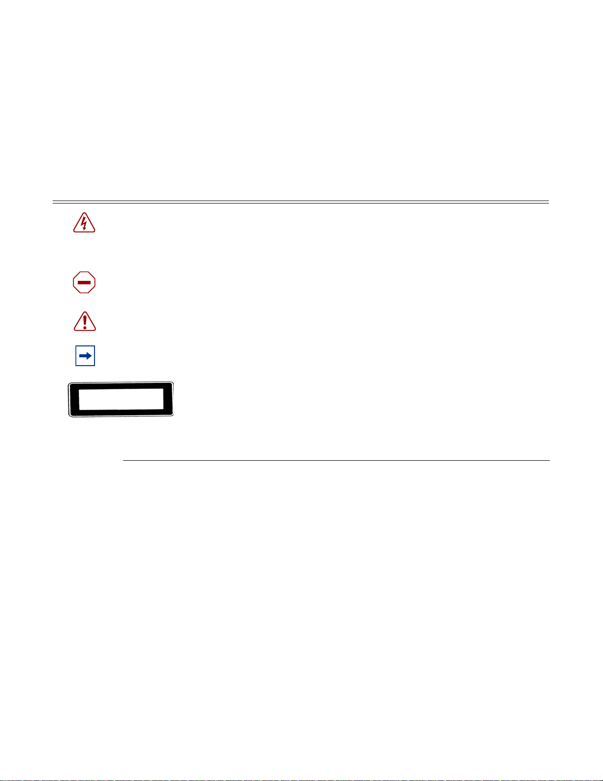
Table 1 describes symbols contained in this guide.
Table 1: Information Symbols
Symbol Meaning Description
Danger This symbol warns that improper handling and installation could result in bodily
injury. An electric shock hazard could exist. Before you begin work on this
equipment, be aware of hazards involving electrical circuitry, networking
environments, and instigate accident prevention procedures.
Caution This symbol warns that improper handling and installation could result in
equipment damage or loss of data.
Warning This symbol warns that improper handling may reduce your co mponent or
system performance.
Note This symbol provides additional operational information.
Class 1 laser products are listed in the MDA installation guides. Only approved
Class 1 replaceable laser transceivers should be used with this product.
Technical Support
Page 10 7210 SAS-X Installation Guide
If you purchased a service agreement for your 7210 SAS-X and related products from a distributor
or authorized reseller, contact the technical support staff for that distributor or reseller for
assistance. If you purchased an Alcatel-Lucent service agreement, contact technical assistance at:
Web: http://www1.alcatel-lucent.com/comps/pages/carrier_support.jhtml

7210 SAS-X Overview
This chapter describes the 7210 SAS-X features and includes the following sections:
• 7210 SAS-X Introduction and Features on page 12
• Switch Architecture on page 13
• Features on page 14
• Hardware Description on page 15
7210 SAS-X Installation Guide Page 11
7210 SAS-X Introduction and Features
SR72033A
7210 SAS-X Introduction and Features
7210 SAS-X supports line-rate switching and provides better service scale along with richer QoS
capabilities, useful for first level of access ethernet aggregation in small and medium access
networks.
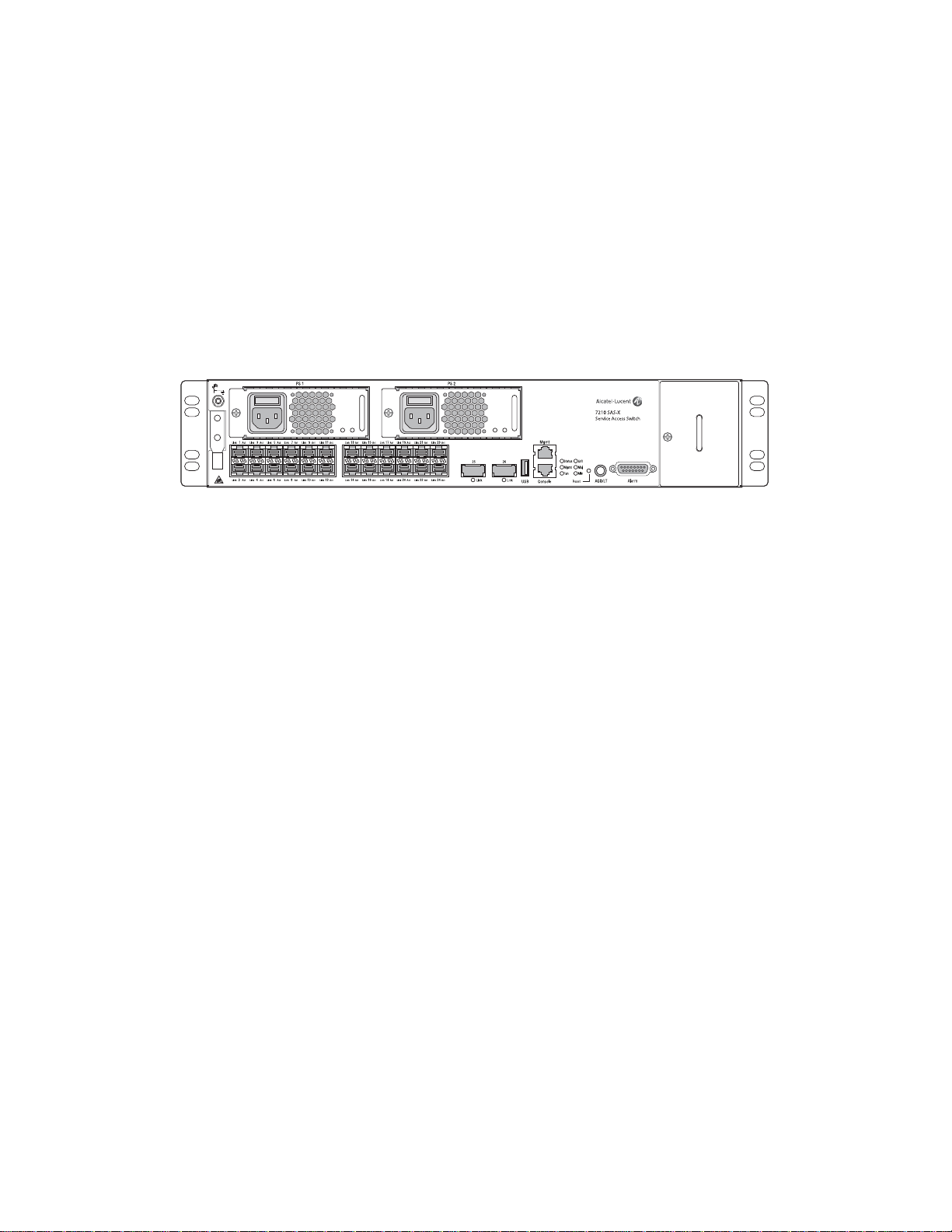
The 7210 SAS-X has one 10/100BASE-TX management port for dedicated management access.
Figure 1: 7210 SAS-X Front Panel
The 7210 SAS-X includes the following features:
• 24 100/1000 SFP ports and 2 10G XFP ports
• One RJ-45 management port for firmware upgrade or system ma nagement
• One RJ-45 console (RS-232 interface) connector for device management
• Embedded SR OS
• Compact size: 2.0RU height, 19-inch rack-mountable metal enclosure, 11-inch depth
(ETSI)
Page 12 7210 SAS-X Installation Guide

Switch Architecture
The 7210 SAS-X employs a wire-speed, non-blocking switching fabric. This permits simultaneous
wire-speed transport of multiple packets at low latency on all ports. The switch also features fullduplex capability on all ports, that effectively doubles the bandwidth of each connection.
Network Management Options
This switch contains a comprehensive array of LEDs for at-a-glance monitoring of network and
port status. It also includes a management agent that enables you to configure or monitor your
switch using its CLI, or by using SNMP applications.
To manage the switch, you can make a direct connection to the console port (out-of-band Ethernet
management port) or you can manage it by using a network connection (in-band SFP or XFP
ports) using Telnet/SSH or SNMP-based network management software.
7210 SAS-X Overview
The management port provides a dedicated management channe l that operates outside of the data
transport network. This makes it possible to reconfigure or troubleshoot the switch over either a
local or remote connection to the management port when access using the data channel is not
possible or deemed insecure.
7210 SAS-X Installation Guide Page 13

Features
Features
The 7210 SAS-X includes the following features:
• Wire speed, non-blocking, service-aware MPLS switch
• 24 100/1000 SFP po r ts
• 2 10G XFP ports
• Powered by SR OS
• Per-service quality of service (QoS) with Hierarchical Ingress Policing and Hierarchical
Egress Shaping, with up to eight egress class-based queues per SAP
• Per-service OAM toolkit with IEEE 802.1ag, IEEE 802.3ah and local service mirroring
• Supports NULL and Dot1Q access SAPs
• Dual homed connections uplinks to separate aggregation device s
• Flexible deployment options with support for mesh and ring topologies
• MEF 9 and MEF 14 certified platform
Connectivity
The 7210 SAS-X includes the following connectivity features:
• Managed by the 5620 SAM
• Provides three isolated alarm inputs and three dry contacts that relay outputs through a
DB-15 interface on the front panel
• Hot-swappable, redundant, load sharing AC or DC power and fan modules
• 100/1000 fiber-optic SFP ports.
• 10G XFP ports
• IEEE 802.3-2005 Ethernet, Fast Ethernet, Gigabit Ethernet, and Ten-Gigabit compliance
ensures compatibility with standards-based network cards and switches from any vendor.
Page 14 7210 SAS-X Installation Guide
Hardware Description
SR72033
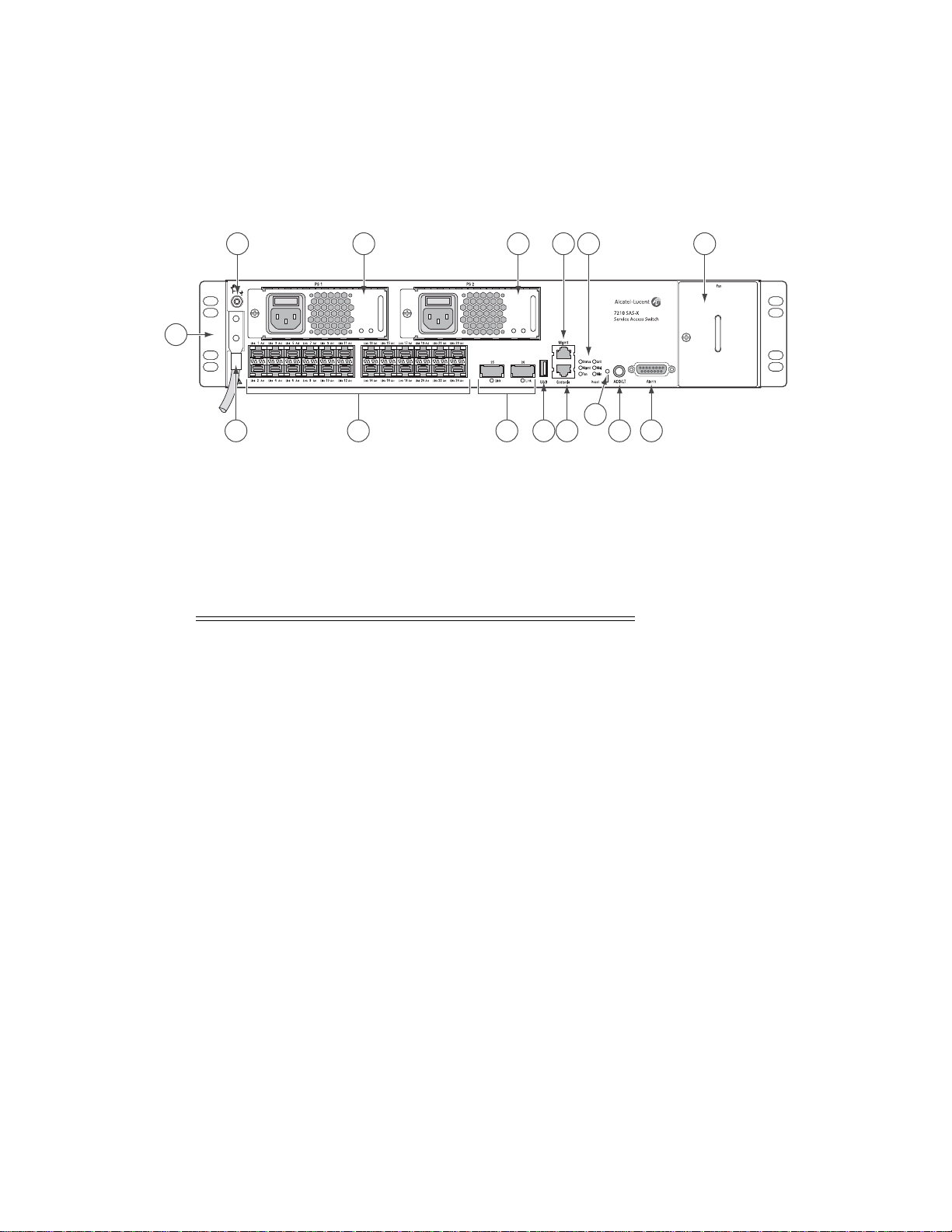
2 5 5 8 1 13
3
9 11 12
10
71 4 6
Figure 2: 7210 SAS-X Front Panel
7210 SAS-X Overview
Table 2: 7210 SAS-X Front Panel Features
Key Description
1 DC power connection
2 Ground lug
3 Rack mounting brackets
4 100/1000 SFP ports and LEDs
5 Power trays
6 XFP ports
7USB port
8 Management port
9Console port
10 Reset button
11 Alarm cut off button
12 Alarm connector
13 Fan tray
7210 SAS-X Installation Guide Page 15

Hardware Description
Ethernet Interfaces
The 7210 SAS-X provides 24 100/1000 SFP ports. Each port can be used for a direct connection to
a subscriber’s Customer Premises Equipment (CPE), or as an uplink to another aggregation node.
The 7210 SAS-X supports 10/100/1000 Base-T copper SFPs. In addition, the 7210 SAS-X
supports 2 x 10G XFP ports. This port can serve as a network uplink to another aggregation node
or as an access port to a subscriber's CPE.
Management Port
The management port provides a dedicated management interface that is segregated from data
traffic crossing the other ports.
Page 16 7210 SAS-X Installation Guide

Console Port
The console port uses an RJ-45 connector with serial pinouts (see Table 10) that ena ble s a
connection to a terminal for performing switch monitoring and configuration operations. The
terminal may be a PC or workstation that is running terminal emulation software, or a terminal
configured as a Data Terminal Equipment (DTE) connection. A null-modem wired serial cable is
supplied with the switch for connecting to this interface.
The serial port configuration requirements are as follows:
• Default Baud rate – 115200 bps
• Character Size – 8 Characters
• Parity – None
• Stop bit – One
• Data bits – 8
• Flow control – none
7210 SAS-X Overview
7210 SAS-X Installation Guide Page 17

Hardware Description
Alarm Interface Port
The alarm interface port is a D-type 15-pin connector that supports a critical alarm output, a major
alarm output, a minor alarm output, and three alarm inputs. When your system has an alarm, the
CPU will drive the alarm relay to issue the alarm output and turn on the associated alarm LED. If
you push the alarm cut off (ACO) button, the relay will be released but the LED will stay on until
the alarm is cleared.
The system signals the appropriate alarm output for the following events:
• Fan failure - Critical alarm is raised.
• One Power Supply Failure - Critical alarm is raised. The critical alarm is cleared and a
major alarm is raised if the failed power supply is removed).
• Chassis temperature threshold exceeded - Major alarm is raised.
The system also supports three alarm inputs. The input voltage range is from 24V to 48V. If an
alarm input is active, the CPU will process it, output it to the CLI, and issue an SNMP trap. An
alarm input can also be configured to drive the appropriate alarm output pin. Please refer the
System Basics user guide for more details on configuring the alarm inputs.
See Table 3 for the alarm interface port pinouts.
Table 3: Alarm Interface Port Pinouts
Pin Name Function
1 MIN_COMMON Common contact for minor alarm relay
2 MAJ_COMMON Common contact for major alarm relay
3 ALARMIN_2_P External alarm input 2 (external relay dry contact closure
to pin 13)
4 CRIT_COMMON Common contact for critical alarm relay
5 CRIT_NORM_CLOSED Normally closed during critical alarm state
6 MIN_NORM_OPEN Normally open during minor alarm state
7 MAJ_NORM_OPEN Normally open during major alarm state
8 CRIT_NORM_OPEN Normally open during critical alarm state
9 ALARMIN_0_P External alarm input 0 (external relay dry contact closure
to pin 14)
Page 18 7210 SAS-X Installation Guide

7210 SAS-X Overview
Table 3: Alarm Interface Port Pinouts
Pin Name Function
10 ALARMIN_1_P External alarm input 1 (external relay dry contact closure
to pin 15)
11 MIN_NORM_CLOSED Normally closed during minor alarm state
12 MAJ_NORM_CLOSED Normally closed during major alarm state
13 ALARMIN_2_R External alarm input 2 (external relay dry contact closure
from pin 3)
14 ALARMIN_0_R External alarm input 0 (external relay dry contact closure
from pin 9)
15 ALARMIN_1_R External alarm input 1 (external relay dry contact closure
from pin 10)
7210 SAS-X Installation Guide Page 19

Hardware Description
1
2
SR72040
Power Modules
The 7210 SAS-X provides two power module options: -48V DC and universal AC. See Figure 3
for an illustration of the power modules.
For specifications on the power supply modules and external input power requirements, see
"Connecting to a Power Source" on page 36 and "Appendix A: Specifications" on page 65.
Figure 3: AC and DC Power Modules
Table 4: Power Module LEDs
LED Condition Status
Input / Output Green DC or AC power is functioning normally.
Output Red AC or DC power is not functioning normally.
Input Off / Red External power not connected or has failed.
Note: When AC and DC power supply is used
simultaneously, and the AC power supply
functions normally while there is no DC input
provided, then the DC power supply input
status LED glows Red.
Page 20 7210 SAS-X Installation Guide

7210 SAS-X Overview
The Input LEDs on the left indicate the status of external power. The Output LED on the right
indicates the status of the internal power conversion process.
Note: You must use AC and/or DC power supplies with your 7210 SAS-X. AC and DC power
supplies can be used simultaneously.
7210 SAS-X Installation Guide Page 21
Hardware Description
SR72034
USB Port
The USB port is reserved for future use.
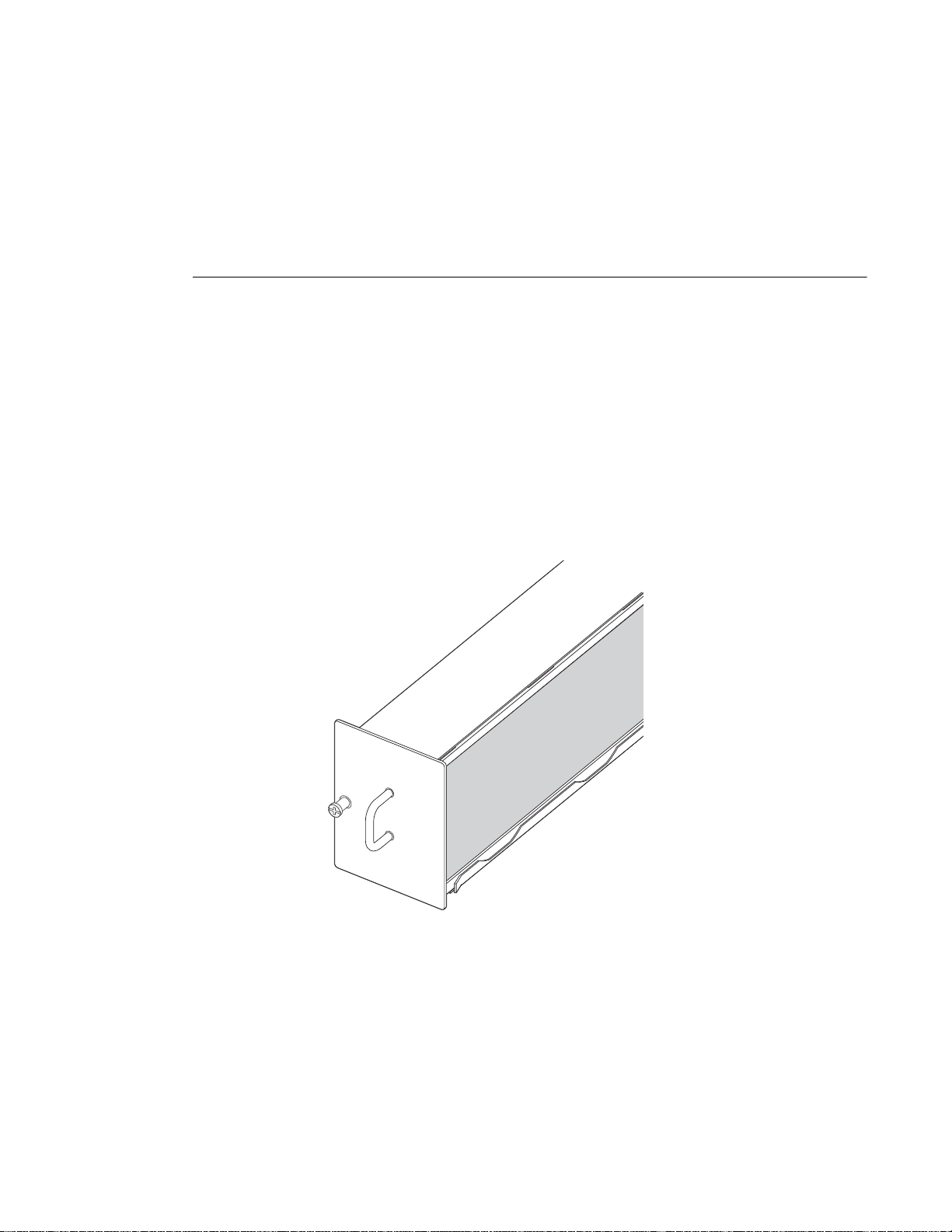
Fan Tray
A hot-swappable fan tray on the right side of the front panel contains three fans that provide
cooling for the chassis. See Figure 4 for an illustration of the fan tray.
The fans are controlled by the system software, and their speed is set according to the
environmental temperature surrounding the switch. Allow at least three inches of clearance on the
sides of the rack to ensure proper airflow intake cooling system. The fan trays must be in place
before the chassis is powered on.
Figure 4: Fan Tray
Page 22 7210 SAS-X Installation Guide
 Loading...