

a
A
EDITION
=
=
==
EE:
PATENTED:
D367.528;
951,428.
2045812;
patents
UNITED
D371.144D371,194:
GERMANY:
2045814;
issued
and
STATES:
D.PB.
No.
2,045813;
pending.
U.
Patent
4,534,756;
CANADA:
EP
Patented/Brevete
P3482620.3;
JAPAN:
REA
S.
AND
P377821
1,743/42.
FOREIGN
5,096,385;
4,898,576,
1,219,497:1,279800:
1.8-08;
M9501997.9;
SWITZERLANO:
PATENTS
5,534,691;
5,542,826;
78.377:
M9,501,997.0;
78,376
M9501995.2;
+EP
0,121,931;
ISSUED
5,537,853;
5,563,347;
and
78,378.
FRANCE:
and
0,328,163;
M9501996.0.
0,328,162;
AND
PENDING.
5,568,912;
Brevet
GREAT
0,248,632;
5,575,632;
5,601,420;
No.
0,121,931; 0,431,310; 0,248,632;
BRITAIN:
122,210;
122,21
Patent
No.
land
5,603,613;
EP
0,121,931;
122,212.
5,609,576;
Other
D367,527;
951,426;
951,427
0,431,310;
US.
and
and
0,248,63;
foreign
This
document
possession
product
specific
This
Technical
does
described.
written
information,
Systems,
142466
ii
MAC“
10221
Signature
contains
not
proprietary
convey
Reproduction,
authorization
Service
please
Manual
call
Technical
Wateridge
Copyright © 1997
Edition™
Technical
any
rights
disclosure,
of
ALARIS
is
subject
Support
Circle,
ALARIS
Service
Manual
information
to
reproduce
Medical
to
change
at
(800)
San
Diego,
Medical
Systems,
of
ALARIS
its
or
use
other
Systems
without
854-77
CA
92121-1579,
Inc.
Medical
contents,
than
is
or
for
strictly
notification.
28
ext.
6003,
Attention:
All
Rights
Reserved.
Systems,
to
manufacture
the
intended
and
forbidden.
For
current
or
write
Technical
¡ts
receipt
or
sell
purpose
technical
ALARIS
Support.
Printed
in
or
any
without
Medical
the
U.S.A.
MEDICAL
SYSTEMS

Phone
Numbers
for
Reference
USA
For
Only
CUSTOMER
placing
TECHNICAL
(800)
For
technical,
QUALITY
(800)
(800)
an
order
checking
(619)
482-4822
for
status
458-6003
OR
854-7128,
troubleshooting
maintenance
ASSURANCE
854-7128
SERVICE
parts,
accessories,
of
an
order.
SUPPORT
EXT.
and
information.
EXT.
7812
etc.,
6003
preventive
and
CANADA
CUSTOMER
For
Western
For
all
CUSTOMER
For
Eastern
For
product
Only
complaints.
.
(800)513-2254
Canada
of
Canada
(800)
to
268-4457
Canada
place
to
SERVICE
to
place
SERVICE
place
orders.
complaints.
orders.
IVAC®
Signature
Edition™
Technical
Service
Manual
iti
WARRANTY
ALARIS
warrants
A.
B.
If
communicate
determine
repair
requiring
purchaser.
risk.
In
consequential
Systems
shall
warranty
loss
Systems
Medical
that:
Each
new
material
and
Directions
purchaser.
The
battery
under
by
any
no
normal
ALARIS
Medical
product
the
or
replacement
service
Loss
event
shall
product.
not
apply
shall
or
damage
product
IVAC®
For
and
requires
directly
appropriate
damages
to
not
arising
Systems,
Inc.,
Signature
workmanship
Use,
from
the
each
new
use
and
service
Systems
service
with
ALARIS
repair
will
be
should
or
ALARIS
This
any
which
be
returned
damage
in
Medical
in
connection
warranty
subsequent owner
apply
to,
and
in
connection
has
been:
(hereinafter
Edition™
under
date
accessory
Pump,
normal
of
delivery
are
for a period
to
the
original
during
the
applicable
Medical
facility.
carried
return
Systems
Except
out
at
promptly,
shipment
be
with
shall
apply
or
ALARIS
Medical
with
the
referred
to as
excluding
use
and
by
ALARIS
free
from
of
ninety
purchaser.
warranty
Systems
ALARIS
liable
the
solely
holder
headquarters
as
provided
Medical
properly
to
the
for
purchase
to
the
of
Systems
purchase
“ALARIS
the
battery,
service,
for
Medical
defects
(90)
in
days
period,
otherwise
Systems's
packaged
repair
any
facility shall
incidental,
or
use
original
the
product.
shall
not
or
use
Medical
is
free
the
period
Systems
material
from
and
the
the
(San
Diego,
in
this
expense.
and
postage
be
indirect
of
any
ALARIS
purchaser.
Furthermore,
be
responsible
of
any
ALARIS
Systems”)
from
defects
stated
to
the
original
in
workmanship
date
of
delivery
purchaser
CA)
warranty,
The
at
should
to
product
prepaid
purchaser's
or
Medical
This
warranty
this
for,
any
Medical
in
the
by
(a)
repaired
representative;
(b)
altered
by
in
products
(c)
subjected
lot
number
(d)
improperly
written
This
warranty
obligations
give
or
assume
use
of
ALARIS
EXPRESS
OR
See
packing
instructions
or
grant,
on
behalf
ALARIS
MEDICAL
OF
FITNESS
inserts
anyone
any
stability
to
misuse
altered,
way
other
so
or
reliability;
or
effaced
maintained
furnished
is
in
lieu
of
all
liabilities
directly
Medical
OR
of
or
indirectly,
of
ALARIS
Systems
SYSTEMS,
IMPLIED,
FOR A PARTICULAR
for
international
than
an
as
to
affect,
negligence
or
removed;
or
used
in
by
ALARIS
other
warranties,
ALARIS
Medical
the
Medical
Systems
products.
INC.,
INCLUDING
warranty,
authorized
in
ALARIS
or
accident,
ALARIS
Medical
or
any
manner
Medical
express
Systems,
authority
to
any
other
DISCLAIMS
ANY
WARRANTY
PURPOSE
if
applicable.
Medical
Systems
or
which
other
has
than
Systems.
or
implied,
and
ALARIS
any
representative
liability
ALL
OR
APPLICATION.
Systems
judgment,
had
the
in
accordance
and
of
Medical
in
connection
OTHER
OF
Systems
or
WARRANTIES,
MERCHANTABILITY
service
the
product
with
all
other
does
other
person
with
serial
the
not
to
the
sale
or
or
№
IVAC®
Signature
Edition™
Technical
Service
Manual
ALARIS
MEDICAL
SYSTEMS
List
Table
Table
Table
Table
Table
Table
Table
Table
Table
Table
Table
Table
Table
of
Tables
1-1
1-2
1-3
1-4
2-1
2-2
2-3
3-1
4-1
4-2
4-3
5-1
5-2
BatteyTripPoints
Common
Abbreviations
ReferenceDesignatol5
Symbol
Definition
Configuration
Druglist............................
Record
of
Configured
............................................
eman
.......................................................
Options
and
Defaults
........................
eme
Instruments
SN
Definition
Battery
Motor
Test
Level
of
Terms
Trip
Points
Control
Equipment
of
Testing
eee
Signals
............
ини
Guidelines
eee
000000000
eee
iii
00000
nene
лилии
KRKA
KRKA
ии
TABLE
E
PARA
mmm
лилии
ana
iii
ema
AE
PRA
PALA
Annan
OF
CONTENTS
mame
ama
anana
erreurs
eren
Ake
Pan
ent
n
ria
шине
té
1-6
1-15
1-16
1-16
2-2
2-7
2-17
3-7
4-3
4-8
4-15
5-1
5-25
Table
6-1
Table
6-2 Error
Table
6-3
Technical
Messages
Battery
Manager
Troubleshooting
Error
Codes
Guide
ae R KKK
nan
Ann
nh K AKA
iria
KE
KA
лишили
RA
AA
AA
PAA R AKA
eee
RA
AKA R LESS
ana
nooo
линии:
nat
anne
6-2
6-4
6-8
MEDICAL
SVITEMS
S
IVAC®
Signature
Edition"
Technical
Service
Manual
Xi

NOTE:
7200G
enable/disable
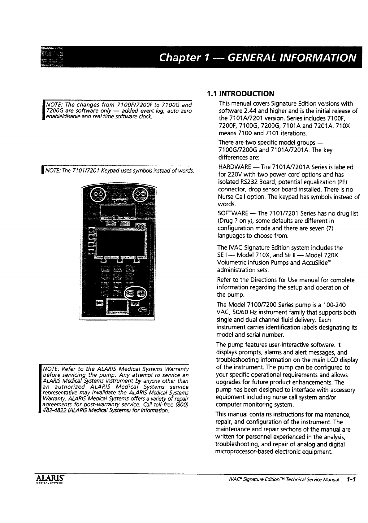
nore:
The
are
software
The
7101/7201
changes
and
from
7100F/7200F
only — added
real
time
software
Keypad
uses
event
clock.
symbols
Chapter 1 —
to
7100G
log,
instead
auto
of
and
zero
words.
GENERAL
1.1
INTRODUCTION
This
manual
software
the
7101A/7201
7200F,
means
There
7100G/7200G
differences
E
7100
are
DO
covers
2.44
7100G,
two
are:
Signature
and
higher
version.
7200G,
and
7101
specific
and
7101A/7201A.
1
wo
power
INFORMATION
Edition
and
Series
7101A
iterations.
model
groups
cord
versions
is
the
initial
includes
and
7201A.
—
The
estica
release
7100F,
key
ana
710X
beled
with
of
NOTE:
before
ALARIS
an
representative
Warranty.
agreements
482-4822
Refer
servicing
Medical
authorized
ALARIS
for
(ALARIS
to
the
ALARIS
the
pump.
Systems
may
post-warranty
instrument
ALARIS
invalidate
Medical
Medical
Medical
Any
Medical
the
Systems
Systems)
ALARIS
offers a variety
service.
Systems
attempt
by
for
to
anyone
Systems
Medical
Call
toll-free
information.
Warranty
service
other
than
service
Systems
of
repair
(800)
an
isolated
connector,
Nurse
words.
SOFTWARE — The
(Drug ? only),
configuration
languages
The
SE | —
Volumetric
administration
Refer
information
the
The
VAC,
single
instrument
model
The
displays
troubleshooting
of
your
upgrades
pump
equipment
computer
This
repair,
maintenance
written
troubleshooting,
microprocessor-based
RS232
Call
IVAC
Signature
Model
to
the
pump.
Model
50/60
and
and
pump
prompts,
the
instrument.
specific
for
has
been
. .
monitoring
manual
and
for
Board,
drop
sensor
option.
to
The
7101/7201
some
defaults
mode
and
choose
from.
Edition
710X,
and
Infusion
Directions
regarding
7100/7200
Hz
dual
carries
serial
features
operational
future
including
contains
configuration
and
personnel
Pumps
sets.
instrument
channel
identification
number.
user-interactive
alarms
information
The
product
designed
,
nurse
system.
instructions
repair
experienced
and
repair
electronic
potential
board
keypad
there
equalization
installed.
has
Series
are
different
are
system
SE
li — Model
and
AccuSlide™
for
Use
manual
the
setup
and
Series
pump
family
that
fluid
delivery.
labels
and
alert
on
the
pump
can
be
requirements
enhancements.
to
interface
call
system
for
of
the
instrument.
sections
of
in
of
analog
equipment.
(PE)
There
symbols
seven
includes
has
instead
no
drug
in
(7)
the
720X
for
complete
operation
is a 100-240
supports
Each
designating
software.
messages,
main
configured
with
and/or
maintenance,
the
the
and
it
and
LCD
and
allows
The
accessory
The
manual
analysis,
digital
is
no
of
list
of
both
its
display
to
are
MEDICAL
AYATA
IVAC®
Signature
Edition®M
Technical
Service
Manual
1-1
GENERAL
INFORMATION
Specifications.
RATE
VOLUME
TO
VOLUME
BE
INFUSED
INFUSED
SYSTEM
DIMENSIONS:
RANGE:
RANGE:
RANGE:
KVO
RANGE:
ACCURACY
ALARMS:
0.1
to
0.1
to
0.1
to
0.1
to
0.0
to
0.1
to
+
5%*
*
Air
In
*
Battery
»
Channel
e
Computer
*
Flow
Width
Height
Depth)
Weight
Power
“without
999.9
ml/hr
in
0.1
270.0
ml/hr
in
0.1
9999.9
999.9
9999.9
20.0
ml
ml
ml
ml/hr
in
in
0.1
in
in
0.1
0.1
0.1
Line
Depleted
Malfunction + Key
Link
Failure + Latch
Sensor
Unplugged ο No
Cord
pole
clampwithout
ml/hr
ml/hr
mi
increments
ml
increments
ml
increments
ml/nr
e
Hold
e
Instrument
7100/7101
7.6
8.6
5.0
6.6
10ft/3
power
increments
increments
(primary)
(secondary)
increments
Time
Exceeded
Malfunction e Occlusion
Stuck
Open
Upstream
in/19.3
in/21.8
in/12.7
lbs./2.9
Flow
ст
cm
cm
kg
m
cord
(primary)
(secondary)
e
Occlusion
e
Primary
e
Set
Detected + Set
7200/7201
10.5
8.6
5.0
8.4 lbs/3.7
10ft/3
[el
Flow
Up
Time
Out
in/26.7
in/21.8
in/12.7
m
Downstream
Upstream
Detected
During
Exceeded
cm
cm
cm
kg
Secondary
ADMINISTRATION
POWER
MODE
GROUND
MAXIMUM
MAXIMUM
TIME
MAXIMUM
OCCLUSION
ENVIRONMENTAL
*
Testing
performed
IEC
1-2
601-2-24
IVAC
using
Signature
REQUIREMENTS:
OF
OPERATION
CURRENT
BOLUS
VOLUME
TO
ALARM
INFUSION
ALARM
CRITICAL
CONDITIONS:
per
proposed
IVAC
IV
sets.
Edition™
CASE:
SETS:
LEAKAGE:
BATTERY:
(ml)
(ml)
PRESSURE
PRESSURE
VOLUME:
standard
Technical
impact
Use
models
100-240V
Internal
resistant
only
IVAC
are
Power
defined
~,
Continuous
Risk
Current
Ground
Patient
(enclosure)
leakage
Rechargeable
Hydride,
pump
operating
12V,
will
on
operate
With a fully
will
be
retained
modes
Trending
At
At
16
12
Maximum
999.9
1.0
ml/hr:
1.0
mi/hr:
psi*
psi
+4psi,
ml/hr.
retain
information
incremental
Temperature
Relative
Atmospheric
Service
Humidity:
Manual
plastic
72
series
administration
on a separate
50/60
Hz,
0.6A
Source.
(normal/singie
leakage
current:
nickel
1.8AHr
less
cadmium.
(minimum)
for 4 hours
both
channels
charged,
special
not
new
for
at
least 6 months.
program
is
retained
0.5
ml:*
60
min*.;
adjustable*
battery
volume
Range:
Pressure:
sets.
card
included
-,
72VA
max — 3-wire
fauit
condition)
current:
than
Use
less
10/50
only
than
yA
IVAC
batteries.With a new,
nominal
at
100
simultaneously.
at
25°C,
volatile
Interrupted
settings
up
to
for 6 hours.
At
25
ml/hr: 0.5
At
25
ml/hr: 2 mint.
in
case
of
single
Operating
10°C
to
40°C
(50°F
to
104°F)
15
to
90%
Non-condensing
631
to
1031
mbar
All
disposable
with
this
Directions
grounded
100/500
(normal/single
Nickel
LA
Cadmium
fully
ml/hr
for a two
memory
secondary
six
hours.
Additionally,
mi*
point
failure
Storage/Transport
-40°C
(-40°F
Non-condensing
631
IV
set
and
IV
set
for
Use.
system.
(normal/single
fault)
or
charged
channel
Class 1 with
Nickel
battery,
instrument
fault)
Metal
configuration
or
advanced
Resistance
will
not
exceed
to
60°C
to
140°F)
5
to
95%
to
1031
mbar
accessory
the
information
operating
1.0
ml
©
ALARIS
MEDICAL
SYSTEMS
1.2
Expanded
Pump
Specifications
GENERAL
INFORMATION
Administration
When
used
gravity
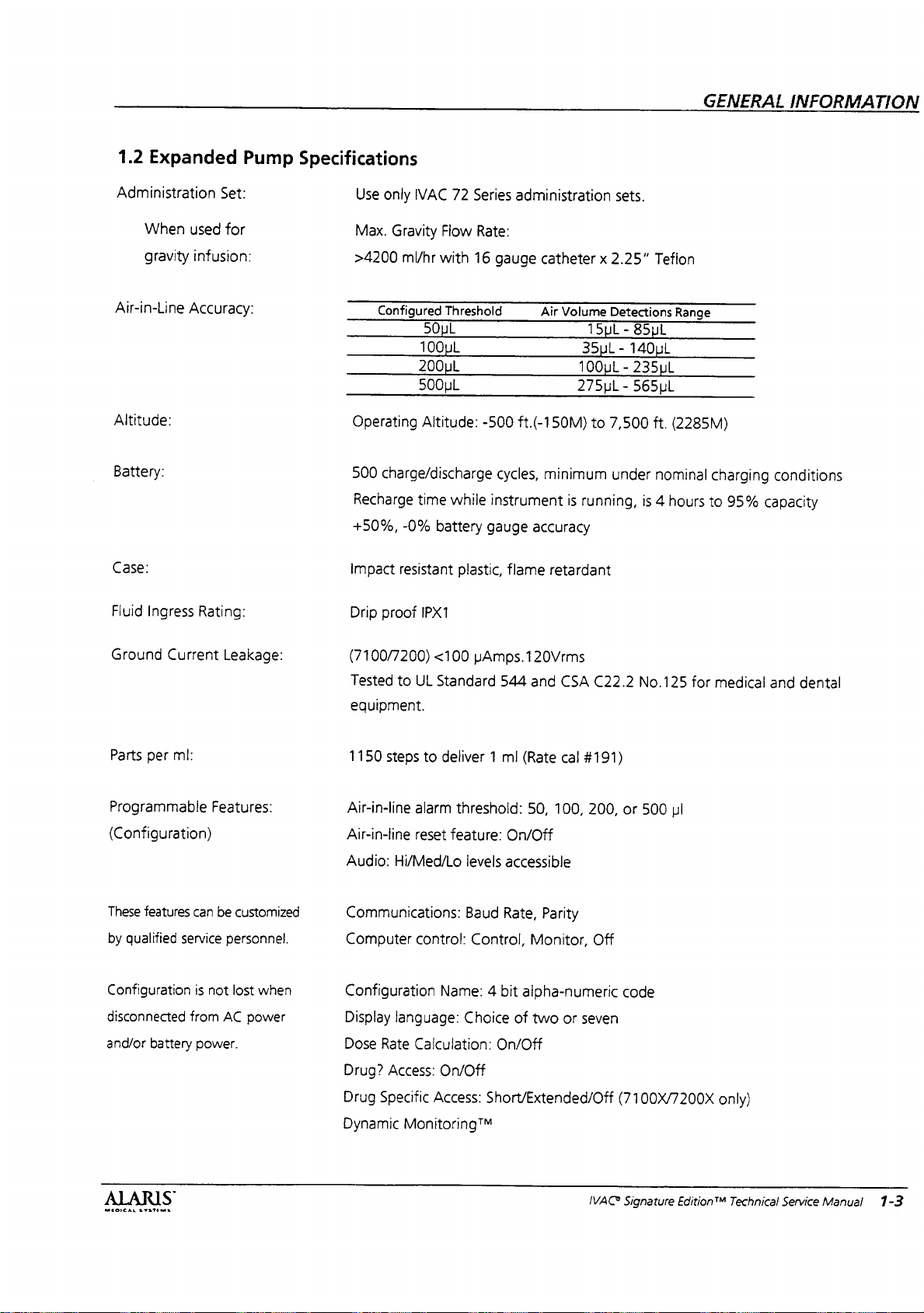
Air-in-Line
Altitude:
Battery:
infusion:
Accuracy:
Case:
Fluid
Ingress
Rating:
Set:
for
Use
only
IVAC
Max.
Gravity
>4200
Operating
500
Recharge
+50%,
impact
Drip
ml/hr
Configured
50uL
100uL
200uL
500LL
Altitude:
charge/discharge
time
-0%
resistant
proof
iPX1
72
Series
Flow
Rate:
with
16
Threshold
-500
while
battery
plastic,
administration
gauge
catheter x 2.25”
Air
Volume
ft.(-150M)
cycles,
minimum
instrument
gauge
accuracy
flame
retardant
sets.
Detections
15uL - 85uL
35uL - 140uL
100uL - 235uL
275uL - 565uL
to
7,500
under
is
running,
is
Teflon
Range
ft.
(2285M)
nominal
4
hours
charging
to
95%
conditions
capacity
Ground
Parts
Programmable
Current
per
ml:
Features:
(Configuration)
These
features
by
qualified
Configuration
disconnected
and/or
can
service
from
battery
be
is
not
power.
Leakage:
customized
personnel.
lost
when
AC
power
(7100/7200)
Tested
equipment.
1150
steps
Air-in-line
Air-in-line
Audio:
<100
to
UL
Standard
to
deliver 1 ml
alarm
reset
feature:
Hi/Med/Lo
Communications:
Computer
Configuration
Display
Dose
Drug?
Drug
Dynamic
control:
language:
Rate
Calculation:
Access:
Specific
Access:
Monitoring™
Name: 4 bit
On/Off
pAmps.120Vrms
544
and
CSA
(Rate
threshold:
levels
Baud
Control,
50,
100,
On/Off
accessible
Rate,
Parity
Monitor,
alpha-numeric
Choice
of
two
On/Off
Short/Extended/Off
cal
or
C22.2
#191)
200,
or
Off
code
seven
(7100X/7200X
No.125
500
pi
for
medical
only)
and
dental
ALARIS
MEDICAL
SYSTEMS
IVAC*
Signature
Editiont“
Technical
Service
Manual
1-3
GENERAL
INFORMATION
Rate
Accuracy:
Mode:
Alert:
Hi
Resistance/Resistance/Pressure
On/Off
Restarts: 0 (Off),
Resistance
Resistance
Instrument
KVO
Loading
Panel
Preventive
Preventive
Maximum
Multi-Dose
Multi-Dose
Multi-Step
Transition
VTBI:
+5%
Display:
Trend
ID: 9 digits
rate:
0.1 - 20.0
Dose:
lock:
On/Off
maintenance
maintenance
rate:
Alert:
Mode:
Mode:
tone:
ON/OFF
typical
at
On/Off
0.1-
On/Off
(7101/7201
30”
1-9
On/Off
Graph:
mlfhr
interval
reminder:
999.9
On/Off
On/Off
On/Off
delivery
On/Off
ml/nr
or
flow
container
1-52
On/Off
sensor
Only
weeks
modification)
head
height
ΚΕΙ:
Temperature:
Volume
Warnings:
to Be
Infused
Range:
Tolerate > 10
Operating
0.1
0.1
0.1 to
0.1
to
0.1
to
0.1
to
e
Battery
e
Checking
e
Computer
e
Dose
e
Load
to
9999.9
to
999.9
999.9
9999.9
999.9
999.9
Complete
Dose
above
Low
V/m
30°C,
ml
in
ml
in
ml
in
0.1
ml
in
mi
per
m!
per
Line
Control
Complete
across
frequency
for
0.1
mi
0.1
ml
increments
ml
increments
0.1
ml
step
in
dose
in
Released
range
extended
increments
periods,
(secondary)
(loading
increments
0.1
ml
increments
0.1
mi
increments
e
e
e
e
will
(primary)
dose)
(dose
rate)
(multi-step)
(multi-dose)
Multi-Step
Resistance
Secondary
VTBI=
0
reduce
Complete
battery
Alert
Complete
life.
1-4
IVAC®
Signature
Edition®*
Technical
Service
Manual
ALARIS
MEDICAL
SYSTEMS
1.3
Battery
This
battery
on
how
the
the
the
detailed
The
Battery
processing
3.06)
performs
e
Controls
e
Provides a battery
e
Monitors
e
Controls
function)
e
Drives
ο
Includes a relative-time
The
processor
processor
which
data
Management
section
battery,
instrument,
main
battery
Battery
using
contains
management
the
Battery
controls
processor.
functional
management
Manager
circuits.
is a custom
the
the
voltage
the
the
Lower
Manager
via a serial
issues
then
responds
this
general
system.
Manager
the
and
provides
Refer
descriptions.
IC
and
The
programmed
following
battery
charger
status
and
instrument
LCD
communicates
data
commands
with
channel.
System
information
Included
monitors
power
various
Battery
functions:
temperature
Display
on/off
support
to
Chapter 4 for
system
consists
sensors
Manager
microcontrolier
“battery
power
source
(See
clock
channel.
to
status
The
the
Battery
information
on
is
information
and
maintains
for
the
functions
more
of
and
IC
(Rev.
gauge”
of
battery
4
(on/off
Figure
1-1)
with
the
main
Manager
the
rest
of
for
the
signal
that
main
and
The
battery
pack
temperature
Manager
The
thermostat
pack
to
monitor
also
which
temperature
temperature
battery
The
constant
Manager
regulates
charger
The
battery
charge,
a.
Fast
battery
by
use
current
turns
average
on
top-up
Charge:
is
more
than
or
self
charge
and
charge
less
unplugged
Ampere-seconds
current
fast
the
of
battery
value,
refer
for
is a continuous 1 Ampere.
charge
battery
charge
and
voltage
or
total
to
Battery
further
GENERAL
(10
to
18V)
has a built-in
sensor
gets
returns
discharge.
details.
which
allows
the
the
temperature
includes a temperature
opens
the
circuit
too
hot
and
closes
to
normal.
circuit
charges
of 1 ampere
the
charger
charge
off
with
cycle
charge,
Fast
charge
than 36°C, and
200
Ampere-seconds
for a day
of
self
is
detected
rises
7°C
is
at
least
declines
charge
Charge
whenever
on.
current
the
appropriate
consists
float
charge,
is
initiated
Leaving
would
cause
discharge.
when
above
its
30°C,
by
192mV
time
exceeds
Regulator
The
by
of
has
the
the
temperature
or
INFORMATION
Battery
of
the
battery.
limiting
if
the
battery
again
when
the
battery
Battery
turning
four
and
whenever
been
through
instrument
about
The
The end
temperature
when
below
3.2
section
with
the
Battery
Manager
the
duty
ratio.
modes;
hot
fast
charge.
the
discharged
actual
200
charge
of
a
of
at
start
the
its
peak
hours.
Also
(4.5.3)
the
a
1.3.1
Fan
The
internal
prolong
fan.
The
fan
“Fast”
time
1.3.2
Battery
The
battery
nickel-cadmium
hours
cycles).
MEDICAL
SYSTEMS
fan
is
used
battery
is
or
battery
life.
always
on
“Top-up”
temperature
and
Charging
is a ten
type
(with a minimum
for
It
is a ball
when
charge.
is
ceil
(1.2V
rated
of
500
cooling,
battery
The
over
mainly
bearing,
is
charging
fan
will
brushless
22°C.
go
Process
per
cell),
high
at
12
volts
and
charge/discharge
to
help
DC
with
on
any
capacity
1.8
amp-
b.
Top-Up
at
the
adding
battery
phase
for
0.9
At
that
charge
the
battery
spent
to
to
the
cool
down
instrument
IVAC
Charge:
end
of
the
last
and
balances
charges
seconds
time,
the
mode.
temperature
cool
180
minutes
time
will
Signature
The
top-up
the
fast
charge
few
percent
individual
at
an
average
every 5 seconds)
instrument
The
charger
will
exceeds
down
to
below
top-up
charge
exceeds 5 1/2
go
into
float
Edition™
Technical
charge
phase
of
charge
cell
rate
of
for
will
go
suspend
37°C.
37°C
hours,
charge
Service
phase
and
finishes
to
the
charges.
180
mA
180
minutes.
into
float
top-up
The
is
in
addition
time.
If
top-up
the
mode.
Manual
begins
This
(1A
if
time
1-5
GENERAL
c.
d.
>36°C
charges
seconds
of
43°C,
temperature
down
time.
the
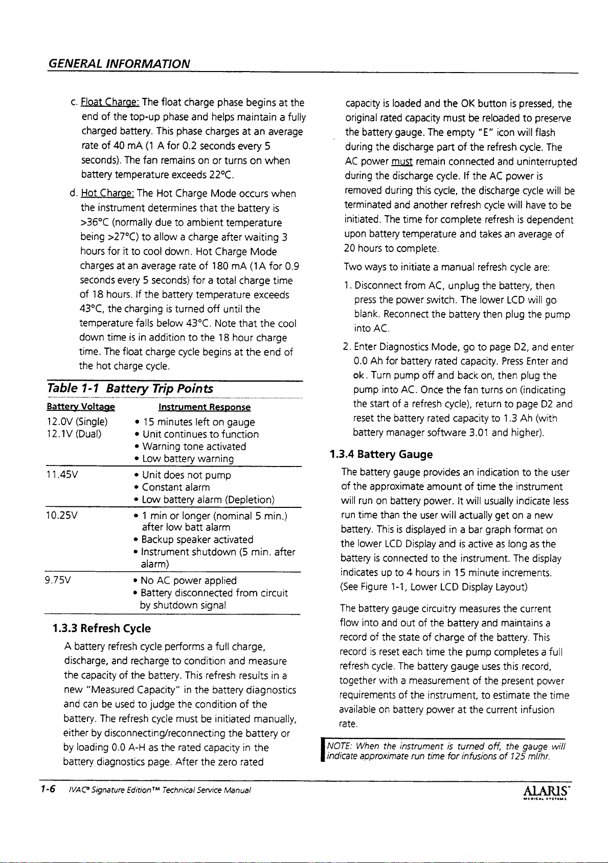
Table
Battery
12.0V
(Single)
12.1V
(Dual)
11.45V
10.25V
9.75V
1.3.3
A
battery
discharge,
the
new
and
battery.
either
by
loading
battery
INFORMATION
Float
Charge:
end
of
charged
rate
of
seconds).
battery
Hot
Charge:
the
instrument
being
>27°C)
hours
for
18
hours.
the
time
The
hot
1-1
Battery
Voltage
Refresh
refresh
capacity
“Measured
can
be
The
by
disconnecting/reconnecting
diagnostics
The
float
the
top-up
battery.
40
mA
The
temperature
This
(1 A for
fan
remains
The
Hot
phase
phase
exceeds
Charge
determines
(normally
it
at
due
to
allow a charge
to
cool
down.
an
average
to
every 5 seconds)
If
the
battery
charging
falls
is
float
charge
below
in
addition
charge
cycle.
is
turned
Trip
Instrument
e
15
minutes
e
Unit
continues
e
Warning
e
Low
battery
e
Unit
does
e
Constant
e
Low
battery
© 1 min
*
e
e
*
Cycle
and
recharge
of
the
used
refresh
0.0
A-H
Capacity”
to
or
after
low
Backup
speaker
Instrument
alarm)
No
AC
power
Battery
by
cycle
disconnected
shutdown
performs a full
to
battery.
judge
cycle
must
as
the
page.
After
charge
0.2
ambient
rate
43°C.
cycle
Points
tone
alarm
longer
batt
condition
This
in
the
rated
phase
and
helps
charges
seconds
on
or
turns
22°C.
Mode
that
the
temperature
after
Hot
Charge
of
180
mA
for a total
temperature
off
until
Note
to
the
18
hour
begins
left
at
Response
on
gauge
to
function
activated
warning
not
pump
alarm
(Depletion)
(nominal 5 min.)
alarm
activated
shutdown
applied
signal
charge,
and
refresh
the
battery
condition
be
initiated
the
capacity
the
zero
begins
at
the
maintain a fully
at
an
average
every
5
on
when
occurs
battery
when
is
waiting
3
Mode
(1A
for
0.9
charge
time
exceeds
the
that
the
cool
charge
the
end
of
(5
min.
after
from
circuit
measure
results
in
a
diagnostics
of
the
manually,
battery
in
or
the
rated
capacity
original
the
during
AC
power
during
removed
terminated
initiated.
upon
20
hours
Two
1.
Disconnect
press
blank.
into
2.
Enter
0.0
ok.
pump
the
reset
battery
1.3.4
Battery
The
battery
of
the
will
run
run
time
battery.
the
lower
battery
indicates
(See
Figure
The
battery
flow
record
record
refresh
together
reguirements
available
rate.
OTE:
When
indicate
approximate
is
loaded
rated
capacity
battery
the
must
the
during
The
battery
to
ways
to
the
gauge.
discharge
remain
discharge
this
and
another
time
temperature
complete.
initiate a manual
from
power
Reconnect
AC.
Diagnostics
Ah
for
battery
Turn
pump
off
into
AC.
Once
start
of a refresh
the
battery
manager
Gauge
gauge
approximate
on
battery
than
the
user
This
is
displayed
LCD
Dispiay
is
connected
up
to 4 hours
1-1,
Lower
gauge
circuitry
into
and
out
of
of
the state
is
reset
cycle.
with a measurement
on
the
of
each
The
battery
of
the
battery
instrument
run
and
the
OK
must
The
empty
part
of
connected
cycle.
If
cycle,
the
refresh
for
complete
and
AC,
unplug
switch.
the
battery
Mode,
rated
and
the
The
go
capacity.
back
fan
cycle),
rated
capacity
software
provides
amount
power.
It
will
actually
an
of
in a bar
and
is
to
the
instrument.
in
15
LCD
Display
measures
the
battery
charge
time
the
gauge
instrument,
power
time
at
is
turned
for
infusions
button
be
reloaded
“E”
icon
the
refresh
and
the
AC
power
discharge
cycle
will
refresh
takes
an
refresh
the
battery,
lower
LCD
then
plug
to
page
Press
on,
then
turns
on
return
to
to
1.3
3.01
and
indication
time
the
will
usuaily
get
graph
active
as
long
minute
increments.
Layout)
the
and
maintains
of
the
battery.
pump
completes a full
uses
this
of
the
present
to
estimate
the
current
off,
the
of
is
pressed,
to
will
cycle.
the
preserve
flash
The
uninterrupted
is
cycle
will
be
have
to
be
is
dependent
average
cycle
D2,
plug
(indicating
page
Ah
are:
then
will
go
the
pump
and
Enter
the
D2
(with
of
enter
and
and
higher).
to
the
user
instrument
indicate
less
on a new
format
The
on
as
the
display
current
a
This
record,
power
the
time
infusion
gauge
125
will
mifhr.
1-6
IVAC
Signature
Edition™
Technical
Service
Manual
1.3.5
Power
The
Battery
power
When
interprets
and
informing
pressed.
power
which
the
power
Battery
instrument.
If
watchdog
switch
turned
Manager.
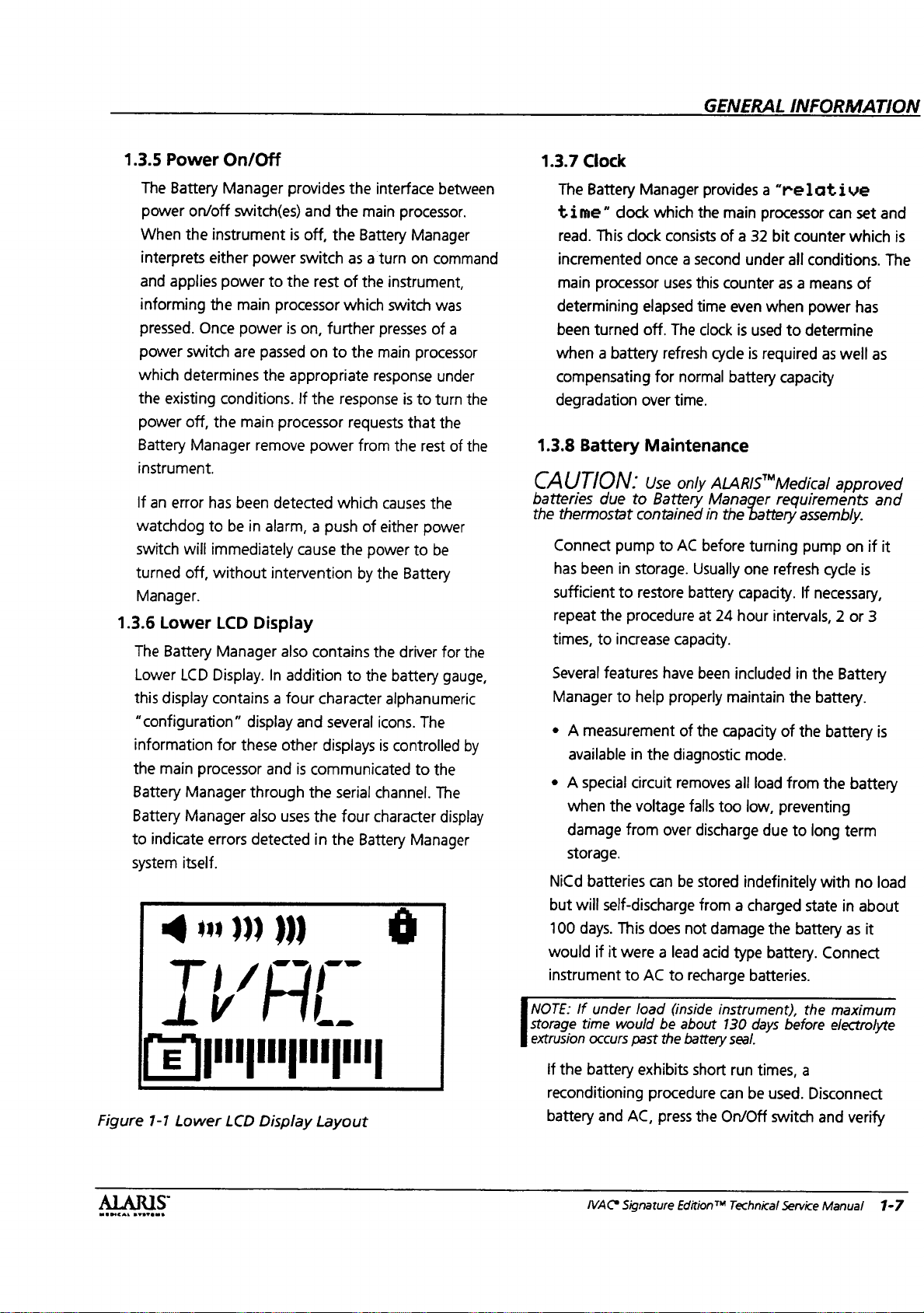
1.3.6
The
Lower
this
“configuration”
on/off
the
applies
switch
determines
existing
off,
Manager
an
error
will
off,
Lower
Battery
LCD
display
either
the
Once
has
to
information
the
main
processor
Battery
Battery
to
systern
Manager
Manager
indicate
errors
itself.
dm)
at
On/Off
Manager
switch(es)
instrument
power
main
power
are
conditions.
the
main
been
be
immediately
without
LCD
Manager
Display.
contains a four
for
these other
グイ
provides
and
is
off,
power
switch
to
the
processor
is
on,
passed
remove
in
on
the
appropriate
If
the
processor
power
detected
alarm, a push
cause
intervention
Display
also
In
addition
display
through
also
and
and
is
the
uses
detected
communicated
ガー
the
the
main
the
Battery
as a turn
rest
of
the
which
further
to
the
response
requests
from
which
of
the
power
by
contains
to
the
character
several
displays
serial
the
four
in
the
Battery
interface
between
processor.
Manager
on
command
instrument,
switch
was
presses
main
response
causes
either
the
the
icons.
is
channel.
character
of
a
processor
under
is
to
turn
that
the
the
rest
of
the
power
to
be
Battery
driver
for
battery
alphanumeric
gauge,
The
controlled
to
the
The
display
Manager
É
the
the
the
by
1.3.7
Clock
The
Battery
time”
read.
This
incremented
main
processor
determining
been
turned
when a battery
compensating
degradation
1.3.8
Battery
CAUTION:
batteries
the
times,
Several
Manager
e A measurement
e
NiCd
but
100
would
instrument
NOTE:
Storage
extrusion
due
thermostat
Connect
has
been
sufficient
repeat
the
to
features
available
A special
when
the
damage
storage.
batteries
will
self-discharge
days.
if
it
If
under
time
occurs
Manager
dock
which
clock
consists
once a second
uses
elapsed
off.
The
refresh
for
normal
over
time.
Maintenance
Use
only
to
Battery
contained
pump
to
AC
in
storage.
to
restore
procedure
increase
to
from
This
were a lead
to
would
capacity.
have
help
properly
in
the
diagnostic
circuit
removes
voltage
over
can
be
does
AC
to
load
(inside
be
past
the
of
not
about
battery
GENERAL
INFORMATION
provides a “relative
the
main
processor
of a 32
this
counter
time
clock
cycle
bit
under
even
when
is
used
is
required
battery
counter
all
conditions.
as a means
power
to
determine
capacity
ALARIS™Medical
Manager
in
the
before
Usually
battery
at
24
been
maintain
the
capacity
falls
too
discharge
stored
from a charged
damage
acid
recharge
instrument),
130
seal.
requirements
battery
assembly.
turning
one
capacity.
hour
included
pump
refresh
If
intervals, 2 or
in
the
of
the
mode.
all
load
from
low,
preventing
due
to
long
indefinitely
state
the
battery
type
battery.
batteries.
days
the
before
necessary,
the
battery.
can
set
which
of
has
as
well
as
approved
and
on
if
cycle
is
3
Battery
battery
the
with
Connect
is
battery
term
no
load
in
about
as
it
maximum
electrolyte
and
is
The
it
Figure
MEDICAL
1-1
Bvstenmi
S
Lower
LCD
Display
Layout
if
the
battery
reconditioning
battery
IVAC
and
AC,
Signature
exhibits
procedure
press
Edition™
short
can
the
On/Off
run
times,
be
used.
switch
Technical
Service
a
Disconnect
and
verify
Manual
1-7
GENERAL
lower
INFORMATION
LCD
instrument
Repeat
times
this
to
increase
conditioner.
CAUTION:
hospital
procedures,
battery
Corporation
1.4
there
protocol.
your
or
contact
(RBRC)
Nicd
Battery
All
batteries
they
are
guaranteed
specifications.
typically
result
Manufacturers
usually
specified
well
expressed
“ideal”
as
the
Manufacturer's
upcoming
November
An
ideal
battery
Ah)
year
1995).
charge
charged
constant
temperature.
charged
for
with a room
The
ideal
discharge
under a C/5
temperature
The
rated
capacity
discharge
discharged
0.9V
type
divided
at
for
at
least 5 hours.
has
different
instance, a battery
may
have
only
As
can
be
seen
are
many
battery
capacity.
goes
blank.
into
AC. A refresh
procedure
capacity
Dispose
of
Refer
to
state’s
EPA
Rechargeable
at
1-800-822-8837.
Capacity
have
specific
to
Deviations
in a reduction
of
nicd
in
Ah
charge
use
of a “new”
date
codes
(e.g.
date
cycle
starts
at
C/10
current
For
15
temperature
constant
discharging
360m-
for
instance, a 1.8Ah
hours
at
starts
current
is
then
by
5.
constant
capacities
rated
1.6Ah
at a 1600mA
from
the
conditions
The
following
Reconnect
at
24
or
or
recycle
your
the
cycle
will
hour
intervals, 2 or
use a battery
battery
institutions
guidelines
Battery
Information
conditions
meet
their
published
from
these
of
available
batteries
(Ampere-Hours),
and
(C
15
180mA
to a cell
Again, a 1.8Ah
Note
at
preceding
rate
capacities,
discharge
battery.
start
code
Battery
on
9/1 of
9611 = first
with a fully
is
the
rated
hours
while
battery
constant
of
23°C.
with a fully
load
charged
at
room
voltage
calculated
as
current
that a given
based
on
1.8Ah
at a 360mA
load.
ideal
which
can
affect
conditions
battery.
Plug
be
initiated.
following
operating
for
disposal
Recycling
under
which
conditions
capacity.
based
on
condition
the
week
discharged
capacity
at
the
ceil
and
the
conditions,
in
room
would
current
battery
of
0.9V.
time
to
would
not
reach
battery
load.
For
load
the
have
the
3
as
of
be
be
of
a
most
practical
this
instrument.
a.
TEMPERATURE
ambient
amount
of
decreased.
an
enclosed
about
90%
accept
the
at
instrument
temperatures
instrument
ways
the
the
battery
internal
battery
b.
CYCLE
and
fan)
temperature
LIFE
go
through
batteries
materials
The
way
the
assume
capacity
and
equivalent
cycles.
the
c.
PARTIAL
is
the
that a battery
at a rate
continually
These
runtime
DISCHARGE/RECHARGE - When a battery
partially
full
time,
capacities
different
then
times.
completed,
progressively
low
apparent
warning
that
The
require
The
reduce
history
and
the
mismatch
lowered
2-3
way
the
the
of
partial
impact
on
DURING
temperature
charge
At an
23°C.
itself
instrument
sees
that
ambient
battery
of
the
Since
case,
above
generates
include
and
turning
will
charge
they
room
limits
gets
AND
AGING - As
many
“wear
out”
in
used
to
construct
instrument
equivalent
reduce
to
30%
per
calculated
displayed
on
discharged,
differences
result
in
cells
If
the
full
the
cell
greater.
This
runtimes
alarms.
The
increases
capacity
full
is
discharge/charge
instrument
runtime
displayed
cycles.
battery
of
the
capacity
CHARGE - As
the
battery
battery
increases,
will
the
temperature
temporarily
it
would
the
batteries
will
be
exposed
accept
otherwise
are
temperature
heat.
Some
the
temperatures
forcing
off
the
too
high.
batteries
air
across
charger
get
charge/discharge
that
the
chemicals
the
cell
break
deals
with
this
will
continually
to
capacity
200
full
values
are
the
battery
then
charged
between
completing
charge
“mismatch”
is
viewed
and
premature
problem
for
not
permanent,
deals
with
based
reduce
30%
over 4 years
at a rate
discharge/charge
used
gauge.
for
individual
charge
sequence
becomes
by
the
low
is
cumulative
every
partial
cycles
to
this
is
on a limited
delivered
effective
the
accept
of
is
35°C,
only
internal
to
to
since
the
of
the
that
it
(an
when
the
older
cycles,
and
down.
is
to
to
reduce
less
than
cell
at
is
not
user
as
battery
in
cycle.
but
may
recover.
to
in
1-8
IVAC®
Signature
Edition"
Technical
Service
Manual
MEDICAL
SYSTEMS
GENERAL
INFORMATION
d.
CHARGE
hours
from
RATE - The
to
get
the
user's
to
provides a multiphase
in
about
80%
capacity
Fast
charge.
designed
individual
essentially
1.3.2
information.
completed,
and
the
Top-up
complete
turned
that
time.
e.
BATTERY
voltage
stops
operating
user
to
discharge
determined
a
battery
reach
the
are
not
before
series
with
actually
permanently
other
hand,
compensate
in
reduced
user
sees
and
alarms.
this
is
to
the
battery
assumed
battery.
the
minimum
all
these
The
to
finish
cells
rematching
for
Fast
Charge
If
then
cumulative
is a 3
hour
it
may
on
and
ALARM
is
the
voltage
plug
it
condition,
by
of
10
end
of
perfectly
others.
The
other
can
go
damages
increasing
for
runtimes
this
as
The
increase
is
not
capacity
The
battery
run
factors
to
the
off
into
0.9V/cell.
cells
into
imperfectiy
premature
way
into
ideal
charge
full
charge,
perspective.
which
The
charge
in
the
next
charge
the
charge
the
fully
charged
them.
and
Top-up
Top-up
the
capacity
charge,
be
over 5 hours
to
cell
mismatch
keep
charge
reduction
but
the
VOLTAGE - The
at
which
and
generates
AC
line.
As
the
end
of
Under
connected
discharge
matched
problem
cells
cell
with
at
so
some
occurs
can
go
below
reversa!,
the
particular
the
alarm
matched
available
low
the
instrument
the
alarm
voltage
damaged
to
gauge
time
below
left
and
that
is
intended
on
account.
rate
requires
is
undesirable
instrument
cycle
which
first 2 hours
phase,
Top-up,
and
to
bring
state,
Refer
to
Section
Charge
is
not
is
not
occurs.
the
elapsed
as
the
charger
battery
cool
battery
the
instrument
an
alarm
to
noted
in
the
discharge
perfect
in
9.0V.
conditions,
series
would
However,
will
reach
when a cell
0.9V
which
cell.
voltage
to
cells
capacity.
battery
warnings
deals
to
guarantee
reduce
printed
the
on
to
the
battery
results
after
is
all
reduced
time
during
alarm
tell
the
ideal
is
cells
0.9V
in
and
On
the
results
The
with
the
show
taking
15
to
is
NOTE:
In
different
different
the
added
5.3
Capacity
1.5
The
the
battery
rated
instrument
and
the
“Replacing
of
Battery.
Dynamic
following
Dynamic
Signature
In
order
for
set, a pressure
gravity
the
setup,
instrument
downstream
The
fundamental
Monitoring"“
flow
from
site
can
be
varying
changes
the
in
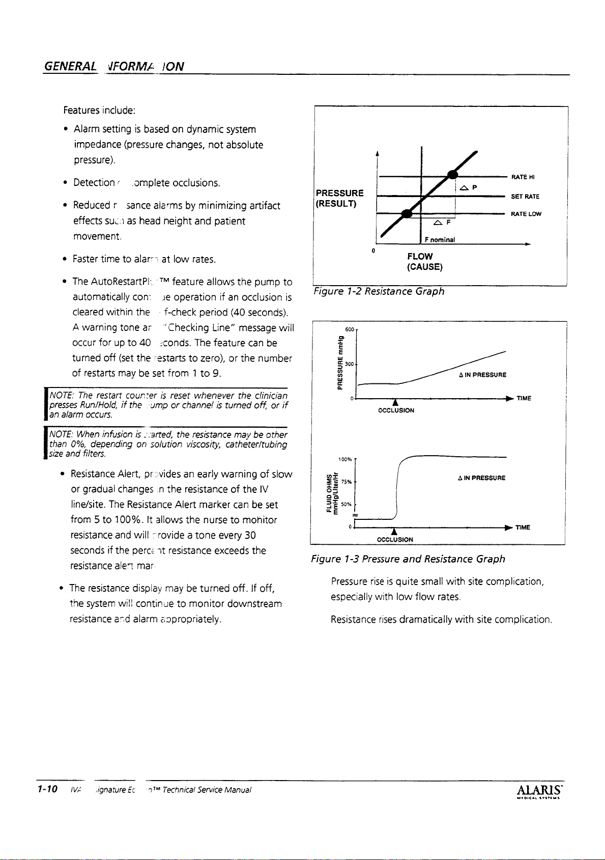
“Resistance
pressure
and
impedance
continuously
of
the
selected
pressure
variations,
measurement.
When a complete
of
the
fluid
infinite).
filters,
Elevated
partial
measured.
The
Dynamic
to
measure
downstream
Pressure = Effect
Resistance = Cause
Resistance = Change
Refer
to
Figure
future,
ALARIS
packs.
capacity.
needs
rated
Battery”
The
Therefore,
to
know
capacity
and
System
is
general
Monitoring™
Edition
the
fluid
the
instrument.
fluid
to
move
difference
this
is
done
will
develop
effects
on
concept
system
mechanism
measured.
flow
rate
while
pressure.
Graph”.
flow
value.
at
data
Such
short
rate.
Signal
Head
likewise,
occlusion
impedance
resistances
occlusions
Monitoring™
mechanical
flow
path.
when a force
when
in
Pressure
Change
in
1-3
“Pressure
Flow
intervals
impediment
Medical
replacement
has
Section
Systems
the
Battery
that a new
changed.
6.4.6,
battery
Monitoring™
information
system
fluid
is
that
This
can
measurements
is
or
as
it
through
the
(gradient)
by
head
height.
pressure
flow.
behind
to
the
resistance
the
is
done
the
patient's
by
monitoring
Refer
to
Figure
processing
then
produce
and
be
height
and
will
not
occurs,
very
the
large
(theoretically
due
to
infiltrations
system
provides a means
properties
is
against a restriction.
to
fluid
(AP)
(AF)
and
Resistance
may
provide
may
have
Manager
battery
has
to
Section
Rated
been
Refer
Changing
(DSM)
regarding
relates
administration
must
to
overcome
Dynamic
intentionally
the
of
can
independent
resulting
affect
resistive
clotting,
can
of
the
flow
the
to
the
exist.
In
In a pump,
to
fluid
infusion
resulting
1-2
the
the
fluid
be
made
the
part
clogged
be
occurs.
Graph”.
a
of
a
MEOICAL
SYSTEMS
IVAC
Signature
Edition™
Technical
Service
Manual
1-9
GENERAL
VFORMA
ION
Features
ES
presses
an
alarm
Ex
than
size
0%,
and
Resistance
or
line/site.
from 5 to
resistance
seconds
resistance
The
the
resistance
include:
Alarm
setting
impedance
pressure).
Detection: .omplete
Reduced r sance
effects
movement.
Faster
time
The
AutoRestartP|.
automatically
cleared
À
warning
occur
for
turned
of
off
restarts
The
restart
Run/Hold,
occurs.
When
infusion
depending
filters.
gradual
resistance
system
(pressure
suc
as
to
within
tone
up
to
(set
may
counter
if
the
Alert,
changes
The
Resistance
100%.
and
if
the
alert
will
and
is
based
on
changes,
occlusions.
alarms
head
neight
alarr=
at
TM
feature
con:
Je
the
-
f-check
ar
“Checking
40
:conds.
the
restarts
be
set
from 1 to
is
reset
-ump
or
is
<arted,
on
solution
provides
.n
the
It
allows
will
-rovide a tone
perce
it
resistance
mar
display
alarm
may
continue
aopropriately.
dynamic
not
by
minimizing
and
patient
low
rates.
allows
operation
period
Line”
The
feature
to
zero),
9.
whenever
channel
the
an
resistance
Alert
the
to
is
resistance
viscosity,
early
marker
nurse
exceeds
be
turned
monitor
system
absolute
artifact
the
pump
if
an
occlusion
(40
seconds).
message
can
be
or
the
number
the
Clinician
turned
off.
or
may
be
catheter/tubing
warning
of
can
to
every
off.
downstream
other
of
slow
the
IV
be
set
monitor
30
the
If
off,
PRESSURE
(RESULT)
to
Figure
is
will
if
Figure
1-2
σι
©
mmHg
w
©
PRESSURE
ol
100%
ま
a
OHMS
FLUID
mmHg/Liter/Hr
o 2
1-3
Pressure
especially
Resistance
Resistance
o
o
OCCLUSION
OCCLUSION
Pressure
rise
is
with
rises
O
F
nominal
FLOW
(CAUSE)
Graph
I
|
pl
and
Resistance
quite
small
low
flow
rates.
dramatically
>
F
41N
A
with
with
P
PRESSURE
>
IN
PRESSURE
>
Graph
site
complication,
site
complication.
RATE
HI
SET
RATE
RATE
LOW
TIME
TIME
1-10
WA
signature
Ëc
nM
Technica!
Service
Manual
ALARIS
MEDICAL
SYSTEME
1.6
Data
The
capability.
monitored
create
on
data
to
support
experience
e
General
for
e
Operation:
modes,
the
e
Instrument
enable
parameters.
Communications
instrument
advanced
communications
technical
user's
or
has
This
allows
by
a
computer,
clinical
technical
and
needs.
Information:
support.
The
instrument's
controls,
point
indicators,
of
Setup:
disable
computer
built-in
remote
features
providing
systems.
is
available
personnel
The
separate
Includes
view.
How
to
set
control,
Function
monitoring
and
their
data
a
means
A
separate
and
organized
with
a
wide
manual
the
phone
communications
and
procedures
the
baud
rate,
and
other
to
be
to
manual
range
of
includes:
number
from
1.7.2
Learn/Teach
This
is a standard
Modem
RS-232
Learn/Teach
instruments
(downloading)
instrument.
1.7.3
Flow
Flow
sensor
kit
on
7100/7200.
drop
the
is
The
flow
chamber.
drip
and
verifies
VTBI
to
be
falling
drops
cable
RS-232
for
the
configuration
Sensor
capability
sensors.
sensor
attaches
It
detects
fluid
flow.
turned
drip
if
GENERAL
RS-232
commercially
cable
purpose
For
off.
chamber
Cable
(also
ALARIS
is
used
of
data
is
available
7101/7201
to
the
empty
an
When
installed,
The
Flow
is
tilted
INFORMATION
available
to
transferring
with
administration
Sensor
9-pin
P/N
133450).
connect
from/to
all
solution
an
that
it
will
another
upgrade
is
container
will
than
more
two
needed
set's
allow
not
Null
The
see
24°.
«
Electrical
information,
for
e
Communications
command
sequences,
1.7
Accessories
Accessory
instrument.
following
1.7.1
Nurse
All
instruments
feature.
be
relayed
No
operating
pump
only
mono
[νοτε:
This
Interfacing:
common
computers.
codes,
and
items
These
paragraphs.
Call
Alarms
to
the
features
will
alarm
additional
phone
option
item
jack
is
RS-232
connectors
Protocol:
data
formats,
error
detection.
are
available
items
are
(7100/7200
are
equipped
and
some
alerts
hospital's
of
the
with
or
without
needed
(P/N
136111).
not
available
background
and
recommended
Inquiry,
message
for
use
described
only)
with
the
from
existing
pump
are
the
is
a
cable
on
7101/7201
response,
with
the
in
the
nurse
the
pump
nurse
call
changed.
nurse
call.
with
a
pumps.
wiring
and
call
will
system.
The
The
9
pin
to
1.8
Summary
The
following
CAUTIONS,
manual.
subject
A
Each
matter.
NOTE
importance
A
CAUTION
result
in
damage
A
WARNING
result
in
personal
1.8.1
Notes
NOTE:
Refer
before
ALARIS
an
representative
Warranty.
agreements
482-4822
NOTE:
storage
extrusion
NOTE:
servicing
Medical
authorized
ALARIS
for
for
If
under
time
occurs
This
option
of
Precautions
is a consolidation
and
WARNINGS
is
repeated
is
information
to
the
reader.
is
a
precaution
to
equipment.
is
a
precaution
or
patient
to
the
ALARIS
the
pump.
Systems
may
post-warranty
information.
load
would
past
instrument
ALARIS
invalidate
Medical
(inside
about
be
battery
the
is
not
available
Systems
of
NOTES,
found
throughout
in
that
context
is
that,
that,
with
of
particular
if
not
if
not
injury.
Medical
Any
Medical Systems
the
service.
instrument),
130
seal.
Systems
attempt
by
ALARIS
offers a variety
days
on
7101/7201
to
anyone
Medical
Call
toll-free
the
before
this
its
related
taken,
can
taken,
can
Warranty
service
other
than
service
Systems
of
repair
(800)
maximum
electrolyte
pumps.
an
ALARIS
MUOICAL
SYSTEMS
IVAC
Signature
Edition™
Technical
Service
Manual
1-11
GENERAL
INFORMATION
“NOTE:
indicate
:
¿different
:
‘the
“added
„5.3
.
.NOTE:
‘presses
an
NOTE:
‘than
size
NOTE:
when
However,
be
record
NOTE:
for
defaults.
NOTE:
Rate
the
NOTE:
modes.
When
approximate
NOTE:
In
different
Capacity
battery
rated
instrument
and
“Replacing
of
The
Run/Hold,
alarm
occurs.
When
0%,
and
filters.
The
disconnected
lost.
If
before
ft
is
a
complete
Setting
will
lower
Maximum
The
the
instrument
run
the
future,
packs.
capacity.
needs
the
rated
capacity
Battery”
Battery.
restart
counter
if
the
infusion
depending
instruments
error
you
strongly
from
history
want
disconnecting
recommended
list
of
the
Maximum
the
KVO
Rate.
maximum
is
tumed
time
for
ALARIS
to
is
on
to
Medical
The
replacement
Therefore,
know
that a new
has
and
Section
is
reset
pump
or
channel
started,
configuration
and
defaults
the
solution
AC
power
infusion
save
this
power.
before
Rate
Rate.
The
rate
setting
off.
infusions
the
changed.
whenever
resistance
viscosity,
program
information
that
below
KVO
applies
the
of
Systems
battery
Battery
battery
Refer
6.4.6,
Changing
is
turned
catheter/tubing
information
and
battery
you
review
selecting
the
rate
will
to
gauge
125
ml/hr.
may
provide
may
have
Manager
has
been
to
Section
Rated
the
clinician
off,
or
may
be
other
is
not
power.
settings
preset
alll
may
be
sure
Table
factory
KVO
not
exceed
infusion
will
a
of
if
lost
to
2-1
“NOTE:
+
;
:
.
:
-through
.
“NOTE:
„
‘
:
-
NOTE:
:
SYSTEMS
samples
NOTE:
-
with
“NOTE:
"NOTE:
_
pressure
If
name,
the
turning
Section
NOTE:
space
NOTE:
settings
NOTE.
pump.
Must
(-)
Only
The
instrument
Repeat
2.5.2
The
level
is
not
the
same
NOTE:
Do
Due
varied
during
check
rate
though
the
The
main
Do
X's
calibration
you
have
pump
off
symbol
from
LEARN/TEACH.
Learn/Teach
the
model
not
to
does
accuracy.
and
instrument
main
software
not
appear
changed
will
or
“Pop-Up
have 4 characters
the
the
allows
display
proceeding
Displays”
to
fill
in
any
configuration
ID
number
diagnostics
you
function
same
on
both
(ie
710x/720x
use
70RCS
more
the
Dynamic
operation.
not
may
PCB
use
7ORCS
For
recommend
Generally,
cause
is
accurate.
board
Rev.
2.02
more
once
pressure
is
required.
the
configuration
the
option
to
the
for
in
open
settings
and
the
mode
reattempt
to
pumps
to
7000A).
than
Monitoring
this
reason,
using
these
the
results
can
only
or
higher.
than
to
teach
mode.
further
explanation.
configuration
character.
will
periodic
will
not
or
will
not
work
or
if
the
40
times.
feature,
ALARIS
automatic
devices
to
be
be
replaced
40
times.
calibration
but
not
rename
be
be
teach
pumps
incorrect
before
Refer
name,
transferred.
maintenance
transferred
next
the
if
revision
are
the
rate
MEDICAL
testers
collect
small
even
in
pumps
|
is
started
or
the
to
use
not
İs
to
if
NOTE:
The
Rate.
NOTE:
automatically
NOTE:
1)
Clear
"NOTE:
Run/Hold
Dose
appears.
NOTE:
upstream
flashing
“No
nurse
NOTE:
seconds,
seconds).
resistance
100%
NOTE:
configuration
Refer
code
configuration
KVO
If
Display
Resistance
is
pressed,
Resistance
is
ends
in
Checking
occlusion
popup
call
Resistance
with a popup
Nurse
measurement
even
when
You
will
to
Section
is
only a hexadecimal
rate
will
is
off
be
tumed
trend
2)
Pump
measurement
pressed
to
Multi-Dose
line
alert
with
display
alert
call
checking
see a 4
2.4.1
(on
will
display
activated.
digit
“Entering
activation.
name upon
name.
not
exceed
then
the
off.
graph
is
off
for
is
put
mode,
applies
one
is
restarted
on
hold
3)
to
tone
for 4 seconds,
give
an
(on
above
the alert
line.
alpha/numeric
entering
Configuration
reflection
the
present
alert
feature
data
is
more
and
Checking
pressure,
at
the
alarm
for 4 seconds,
This
configuration
of
lost
than 6 hours.
at
0%
again
to
line
resistance
beginning
off
for 6 seconds).
tone
every
occurs
when
threshold
code
next
Mode” . This
your
instruments
Maximum
will
when:
‘when:
start,
message
and
and
thirty
off
for
the
or at
to
the
mode.
1)
2)
a
6
NOTE:
The
with
main
software
NOTE:
The
|
NOTE:
Refer
“Main
Power
through
NOTE:
(>37°
included
“NOTE:
disconnected,
„generating
instrument
reconnected.
NOTE:
instrument
.
pump.
NOTE:
disconnecting
program
record
NOTE:
disconnected.
4.5.17.
The
O)
to
in
The
The
Instrument
settings
before
The
main
PCB
board
Rev.
alarm
history
to
Figure
4-5
Supply”
charger
let
the
instrument's
to
depend
will
the
battery
180
minute
is
the
the
SHUT-DOWN*
be
plugged
tests
to
be
on
configuration
power.
may
proceeding.
instrument
be
can
2.02
is
when
turn
same
the
However,
lost.
only
or
higher.
not
stored
“Battery
cool
charge
operation,
into
performed
Monitor”
following
off
if
the
down.
time.
as
the
signal
AC
after
level
of
If
you
will
not
will
history
want
be
replaced
in
the
battery
Cool
when
Battery
and
the
on a just-repaired
repairs
not
run
in
EEPROM.
and
Figure
Sections
gets
time
the
battery
Manager
reguires
has
made
be
lost
and
infusion
save
event
with
too
battery
down
battery
to
pumps
4.5.2
is
been
to
when
4-6
hot
not
is
the
the
log,
1-12
IVAC®
Signature
Edition®*
Technical
Service
Manual
MEDICAL
SYETEMS
GENERAL
NOTE:
Selected
not
will
_
Calibration
:
NOTE:
As a result
part
number
requested,
noted.
1.8.2
Cautions
CAUTION:
batteries
the
thermostat
CAUTION:
hospital
procedures,
battery
Corporation
CAU
not
CAUTION:
do
re-powering
operate
battery
CAUTION:
over
protocol.
or
TION:
in
use.
not
replace
unless
replacement.
time.
INFORMATION
Tc=0.0
get
Perform
(soft).
but
due
your
contact
(RBRC)
the
Temp
of
continuing
you
receive
will
be
use
only
to
Battery
contained
Dispose
Refer
state’s
Rechargeable
at
keep
when
dead
instrument.
it is
first
Alcohol
with
software
Cal
may
interchangeable,
ALARIS
Manager
in
the
of
or
to
your
EPA
guidelines
is
message
product
not
match
Medical
requirements
battery
recycle
battery
institution's
Battery
1-800-822-8837.
latch
closed
there
battery
connected
will
cause
is
The
no
when
AC
for
instrument
to
the
2.02
or
when
development,
unless
higher.
in
pressure
the
one
otherwise
approved
assembly.
following
operating
for
disposal
Recycling
instrument
power
the
AC
key
available,
purpose
will
power
pad
to
If
the
you
and
of
is
of
not
after
crack
CAUTION:
batteries
the
1.8.3
due
thermostat
Warnings
WARNING:
is
Changed,
changed
The
one
Refer
to
intent
set
to
of
of
Section
parameters
WARNING:
mode
during
configuration
WA
RN
preventive
improper
ING:
maintenance
instrument
WARNING:
the
power
cleaning.
immerse
Do
the
cord
pump,
case.
WARNING:
before
when
of
disassembling.
AC
power
the
ON/OFF
use
to
only
Battery
contained
When
the
configuration
document
the
configuration
2.5.2
“Pop-Up
Powering
an
alarm
changes.
Failure
operation.
Turn
from
not
steam
or
Disconnect
Hazardous
is
connected
switch.
ALARIS
Manager
in
the
an
instrument's
the
new
for
each
Displays”
down
or
error
to
inspections
the
instrument
the
AC
autoclave,
allow
fluids
pump
regardless
Medical
requirements
battery
assembly
configuration
name
should
parameter
name
is
to
alpha-numeric
in
configuration
will
not save any
perform
regular
may
off
and
wall
outlet
EtO
to
enter
from
voltages
are
of
approved
and
also
be
settings.
have
only
code.
and
result
in
unplug
before
sterilize,
the
pump
AC
power
present
the
setting
CAUTION:
probe
to
pressure
CAUTION:
assemblies,
static
grounding
CAUTION:
channel
is
the
as
or
removed,
pump
well
as
rate
with
will
Do
not
transducer.
To
avoid
use
extreme
techniques.
Do
not mix
other
it
must
need
instruments.
go
hard and
calibration.
connect
serious
care
back
in
ground
damage
and
mechanisms
When a mechanism
the
soft
pressure
to
always
original
resistance
the
board
use
proper
in
dual
position
or
calibration
WARNING:
verification
removed
and
disconnected
WARNING:
instrument
voltages
regardless
when
are
of
Always
after
mechanism
reinstalled
and
reconnected.
Use
connected
present
the
setting
perform a rate
and
or
extreme
when
of
to
AC
the
caution
AC
power
board
cables
power
power
switch.
accuracy
have
have
in
servicing
Hazardous
is
connected
been
been
the
1-14
IVAC®
Signature
Edition®M
Technical
Service
Manual
MEDICAL
svevems
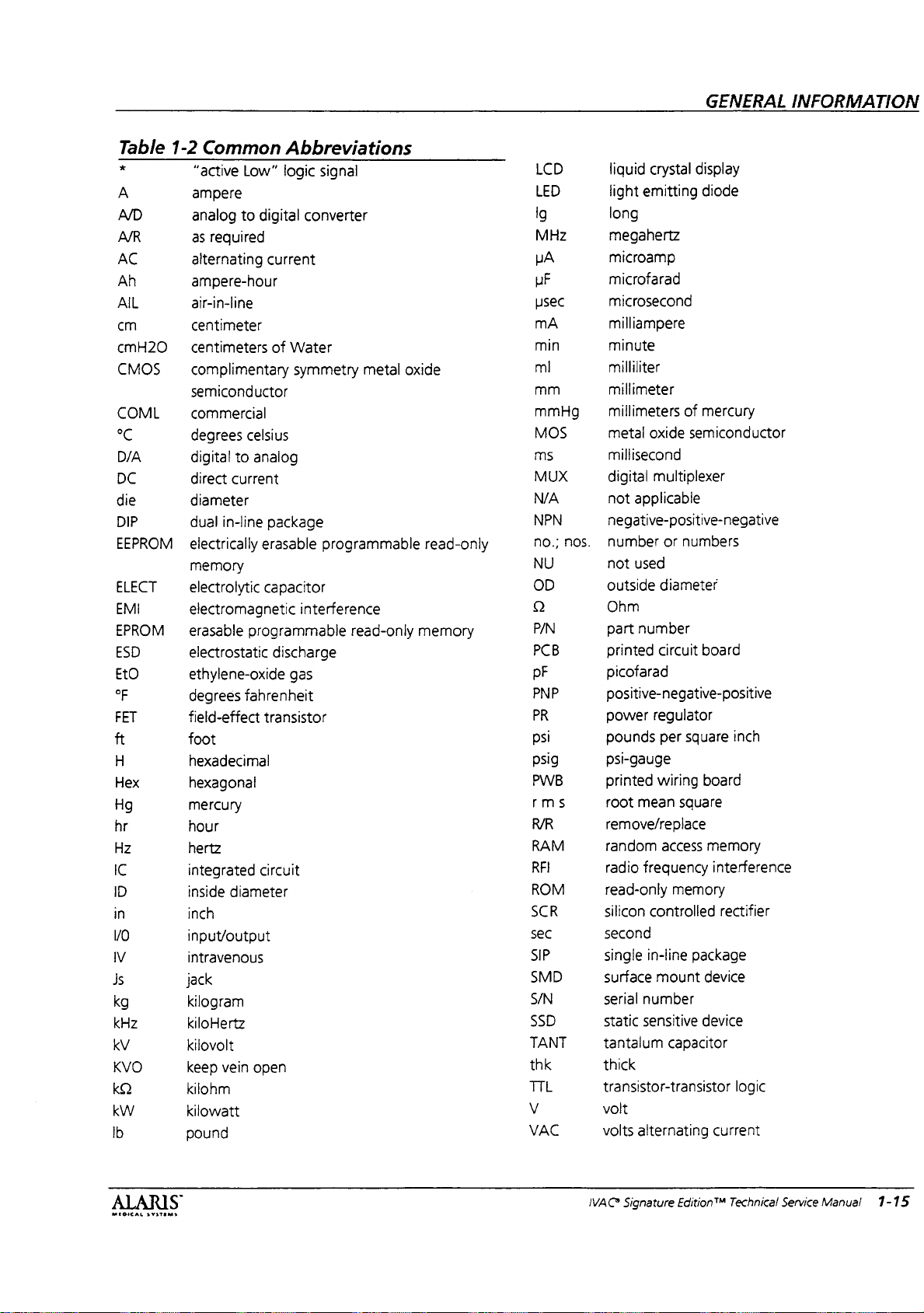
GENERAL
INFORMATION
Table
*
A
A/D
A/R
AC
Ah
ΑΙ.
cm
cmH20
CMOS
1-2
Common
“active
ampere
analog
as
required
alternating
ampere-hour
air-in-line
centimeter
centimeters
complimentary
semiconductor
COML
°C
D/A
DC
die
DIP
EEPROM
commercial
degrees
digital
direct
diameter
dual
in-line
electrically
memory
ELECT
EMI
electrolytic
electromagnetic
EPROM _ erasable
ESD
EtO
°F
FET
ft
H
Hex
Hg
hr
Hz
IC
ID
in
νο
М
Js
kg
kHz
kV
KVO
Κω
kW
lb
electrostatic
ethylene-oxide
degrees
field-effect
foot
hexadecimal
hexagonal
mercury
hour
hertz
integrated
inside
diameter
inch
input/output
intravenous
jack
kilogram
kiloHertz
kilovolt
keep
vein
kilonm
kilowatt
pound
Abbreviations
Low”
logic
to
digital
current
of
Water
symmetry
celsius
to
analog
current
package
erasable
capacitor
interference
programmable
discharge
gas
fahrenheit
transistor
circuit
open
signal
converter
metal
programmable
read-only
oxide
read-only
memory
LCD
LED
MHz
HA
UF
usec
mA
min
ml
mm
mmHg
MOS
ms
MUX
N/A
NPN
no.;
NU
OD
P/N
PCB
pF
PNP
PR
psi
psig
PWB
rms
RAM
RFI
ROM
SCR
sec
SIP
SMD
S/N
SSD
TANT
thk
TTL
VAC
liquid
crystal
display
light
emitting
diode
long
megahertz
microamp
microfarad
microsecond
milliampere
minute
milliliter
millimeter
millimeters
metal
of
mercury
oxide
semiconductor
millisecond
digital
multiplexer
not
applicable
negative-positive-negative
nos.
number
not
outside
Ohm
part
printed
or
used
diameter
number
circuit
numbers
board
picofarad
positive-negative-positive
power
regulator
pounds
per
square
psi-gauge
printed
root
remove/replace
random
radio
read-only
silicon
wiring
mean
square
access
frequency
memory
controlled
board
memory
interference
rectifier
second
single
in-line
package
surface
serial
static
tantalum
mount
device
number
sensitive
device
capacitor
thick
transistor-transistor
volt
volts
alternating
current
inch
logic
MEOICAL
SYSTEMS
S
IVAC
Signature
Edition™
Technical
Service
Manual
1-15
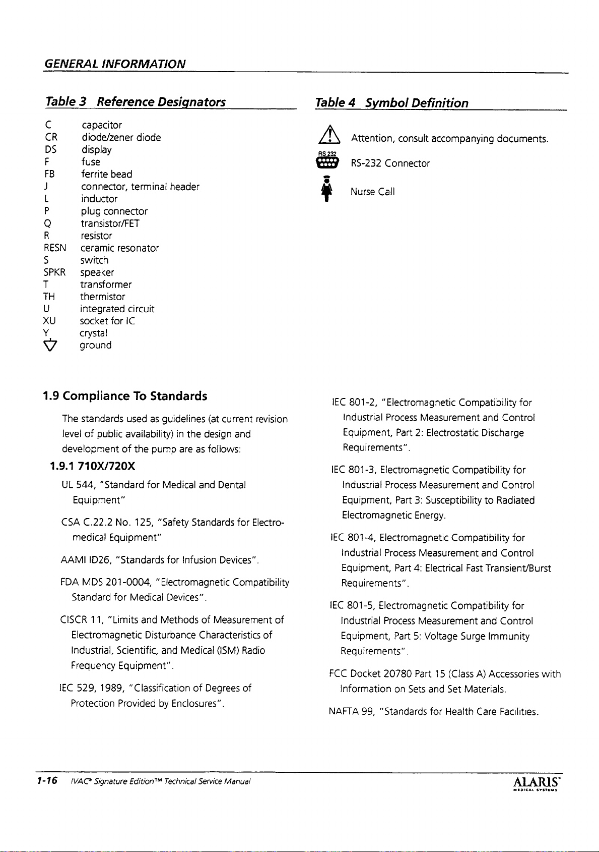
GENERAL
INFORMATION
Table 3 Reference
C
CR
DS
で
ユ
ー
マビ
の
〇
の
つつ
の
mn
ヨゴ
き で
で
capacitor
diode/zener
display
fuse
m
ferrite
connector,
inductor
plug
transistor/FET
resistor
un
2
ceramic
m
switch
U 六 2
speaker
transformer
thermistor
integrated
socket
crystal
ground
diode
bead
terminal
connector
resonator
circuit
for
IC
Designators
header
Table 4 Symbol
个
RS
EX
=
©
4
Attention,
232
RS-232
Nurse
consult
Connector
Call
Definition
accompanying
documents.
1.9
Compliance
The
standards
level
of
development
1.9.1
710X/720X
UL
544,
Equipment”
CSA
C.22.2
medical
AAMI
FDA
MDS
Standard
CISCR
Electromagnetic
Industrial,
Frequency
IEC
529,
Protection
public
of
“Standard
No.
Equipment”
ID26,
“Standards
201-0004,
for
11,
“Limits
Scientific,
Equipment”.
1989,
Provided
To
Standards
used
as
guidelines
availability)
the
125,
pump
for
Medical
“Safety
for
in
the
are
Standards
Infusion
“Electromagnetic
Medical
and
Devices”.
Methods
Disturbance
and
Medical
“Classification
by
of
Enclosures”.
(at
current
design
as
foliows:
and
Dental
Devices”.
and
for
Electro-
revision
Compatibility
of
Measurement
Characteristics
(ISM)
Degrees
of
Radio
of
of
IEC
801-2,
Industrial
“Electromagnetic
Process
Equipment,
Requirements”.
IEC
801-3,
Industrial
Electromagnetic
Process
Equipment,
Electromagnetic
IEC
801-4,
industrial
Equipment,
Requirements”.
IEC
801-5,
Industrial
Electromagnetic
Process
Electromagnetic
Process
Equipment,
Requirements”.
FCC
Docket
information
NAFTA
20780
99,
"Standards
Measurement
Part
2:
Measurement
Part
3:
Energy.
Measurement
Part
4:
Measurement
Part
5:
Part
on
Sets
Compatibility
and
Electrostatic
Discharge
Compatibility
and
Susceptibility
to
Compatibility
and
Electrical
Fast
Transient/Burst
Compatibility
and
Voltage
and
for
15
Set
Health
Surge
(Class
Materials.
Immunity
A)
Accessories
Care
for
Control
for
Control
Radiated
for
Control
for
Control
with
Facilities.
1-16 | IVAC*
Signature
EditionT“
Technical
Service
Manual
MEDICAL
S
SYSTEMS
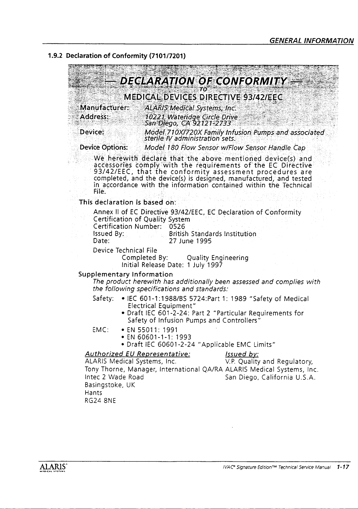
1.9.2
Declaration
A
Device
This
Supplementary
Authorized
ALARIS
Tony
Intec 2 Wade
Basingstoke,
Hants
RG24
of
Conformity
Options:
We
herewith
‘accessories
‘93/42/EEC,
completed,
in
‘accordance
ile.
declaration
Annex
Certification
Certification
Issued
Date:
Device
The
the
Safety: e IEC
EMC:
II
of
By:
Technical
Completed
Initial
product
following
e
e
e
e
Medical
Thorne,
8NE
Electrical
Draft
Safety
EN
EN
Draft
EU
Manager,
Road
UK
(7101/7201)
2
Mo
el.
DO
|
Sterile
=
Model
déclare
comply:with
that
and
the
with
is
based
EC
Directive
of
Ouality
Number:
File
Release
Information
herewith
specifications
601-1:1988/BS
IEC
55011:
60601-1-1:
IEC
Representative:
Systems,
IV
180
that
the
conformity
device(s)
the
information
2
on:
93/42/EEC,
System
0526
_
British
27
By:
Date: 1 July
has
Eguipment"
601-2-24:
of
Infusion
1991
60601-2-24
Inc.
International
Family
administration
Flow
Sensor
the
above
thè
requirements
is
designed,
=
sets.
w/Flow
assessment
contained
EC
Declaration
Standards
June
1995
Quality
additionally
and
5724:Part
Part 2 “Particular
Pumps
1993
Engineering
1997
been
standards:
1:
and
Controllers”
“Applicable
QA/RA
infusion
Sensor
mentioned
of
manufactured,
within
Institution
assessed
1989
Issued
V.P.
ALARIS
San
"Safety
Requirements
EMC
by:
Quality
Medical
Diego,
GENERAL
Pumps
the
of
Limits”
and
Handle
device(s)
EC
procedures
and
the
Conformity
and
complies
of
and
Regulatory,
Systems,
California
INFORMATION
associated
Cap
and
Directive
are
tested
Technical
with
Medical
for
Inc.
U.S.A.
.
ae
ALARIS
IVAC
Signature
Edition™
Technical
Service
Manual
1-17

i
Chapter
2
—
CHECKOUT
AND
CONFIGURATION
CAUTION:
not
in
use.
keep
latch
closed
when
instrument
is
2.1
Introduction
This
chapter
configuration
chapter
Configured
recording
is a reproducible
Instruments,
and
instruments
reference, a fold-out
screens
2.2
New
Refer
manual
setting
When
instrument
segments
performed
During
a
it
is
Instrument
to
the
for
up
turning
operation,
self
test,
detects
an
provided
instructions
the
beeps
flash.
its
and
describes
of
the
the
instrument.
form
Table
tracking
located
instrument's
instrument
on
This
self
will
internal
configurations
in
different
map
of
at
the
end
Checkout
Directions
regarding
for
the
instrument,
and
that
confirms
test,
and
the
pump
alarm
and
malfunction.
initial
setup
and
Included
(Record
2-3)
of
available
for
areas.
For
all
the
configuration
of
this
chapter.
For
Use
unpacking
the
first
time.
verify
that
all
display
that
is
operating
continually
display a message
LED
the
pump
correctly.
performs
in
this
for
your
(DFU)
and
the
has
if
MEDICAL
SYSTEMS
Service
pass
to
shows
to
Information
Chapter 6 of
Use.
For
checks
is
required
the
start-up
qualified
physical
complete
new
instrument
are:
*
Functional
e
Ground
e
Flow
Stop
*
Instrument
e
Rate
Verification
e
Pressure
»
Set
Sensor
IVAC
Signature
service
the
about
Current
Verification
if
the
pump
sequence.
personnel
damage,
self
is
test,
or
instrument
this
manual
Test
and
checkout,
(Chapter
Leakage
Test
(Chapter
Configuration
(Chapter
(Chapter
Check
(Chapter
Edition™
Technical
fails
to
Refer
the
if
the
instrument
out
of
calibration,
continues
alarms
in
the
the
minimum
3)
Test
(Chapter
3)
(Chapter
3)
3)
3)
Service
satisfactorily
instrument
fails
to
alarm.
is
found
Directions
in
For
3)
2)
Manual
2-1
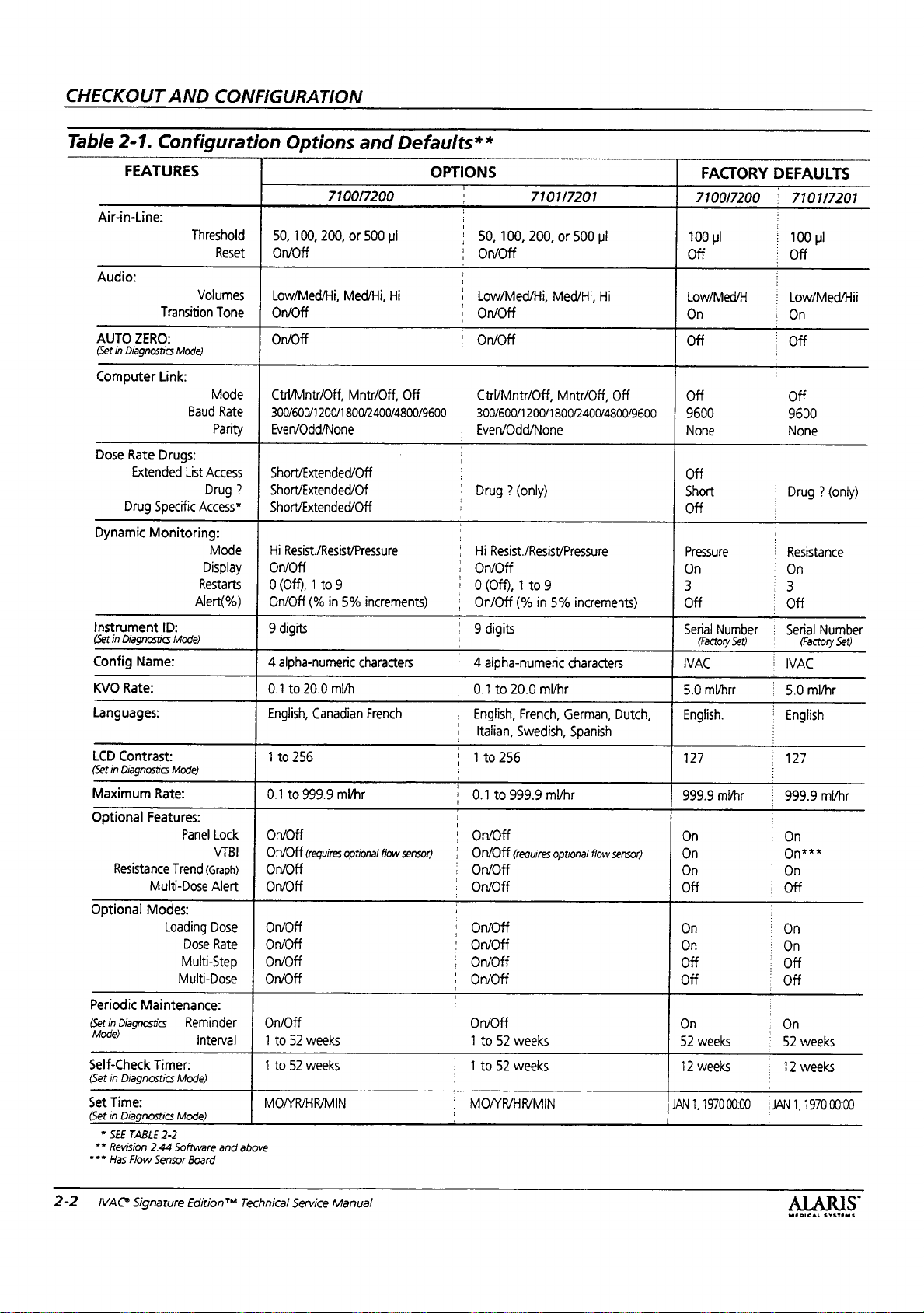
CHECKOUT
Table
2-1.
FEATURES
Air-in-Line:
Audio:
AUTO
ZERO:
(Set
in
Diagnostics
Computer
Dose
Rate
Extended
Drug
Dynamic
Instrument
(Set
in
Diagnostics
Config
Name:
KVO
Rate:
Languages:
LCD
Contrast:
(Set
in
Diagnostics
Maximum
Optional
Resistance
Optional
Periodic
(Set
in
Diagnostics
Mode)
Self-Check
(Set
in
Diagnostics
Set
Time:
(Set
in
Diagnostics
*
SEE
TABLE
**
Revision
***
Has
Flow
AND
CONFIGURATION
Configuration
Threshold
Reset | On/Off
Volumes
Transition
Link:
Drugs:
Specific
Monitoring:
ID:
Rate:
Features:
Multi-Dose
Modes:
Loading
Maintenance:
Timer:
2-2
2.44
Sensor
Tone | On/Off
Mode)
Mode | Ctr/Mntr/Off,
Baud
Rate
Parity | EvervOdd/None
List
Access
Drug ? Short/Extended/Of
Access*
Mode | Hi
Display | On/Off
Restarts 0 (Off), 1 to
Alert(%)
Mode)
Mode)
Panel
Lock | On/Off
VIBI
Trend
(Graph) | On/Off
Alert | Οπ/ΟΗ
Dose
Dose
Rate
Multi-Step | On/Off
Multi-Dose | On/Off
Reminder
interval 1 to
Mode)
Mode)
Software
and
Board
above.
Options
50,
100,
Low/Med/Hi,
ОПОН
and
7100/7200
200,
or
500
Med/Hi,
Defaults**
OPTIONS
ul
Hi
!
'
1 ;
i
‚
'
!
7101/7201
50,
100,
200,
On/Off
Low/Med/Hi,
ОПОН
On/Off
or
500
Med/Hi,
pl
Hi
!
Mntr/Off,
300/600/1200/1800/2400/4800/9600 | 300/600/1200/1800/2400/4800/9600
Short/Extended/Off
Short/Extended/Off
Resist/Resist/Pressure | Hi
9
On/Off
(%
in
5%
9
digits
4
alpha-numeric
0.1
to
20.0
ml/h
English,
Canadian
1
to
256
0.1
to
999.9
mi/hr
Off
increments)
characters
French
,
Ctr/Mntr/Off,
|
Even/Odd/None
:
Drug?
(only)
;
:
Resist./Resist/Pressure
‚
On/Off
: 0 (Off), 1 to9
,
OnmOff
| 9 digits
i
| 4 alpha-numeric
;
0.1
to
20.0
‚
English,
‚
Italian,
' 1 to
256
0.1
to
999.9
Mntr/Off,
(9
in
5%
characters
ml/hr
French,
German,
Swedish,
Spanish
mVhr
increments)
|
|
On/Off
On/Off
(requires
optional
flow
On/Off
On/Off
On/Off
52
weeks
1
to
52
weeks
MO/YR/HR/MIN
sensor) | On/Off
‚
:
+
'
;
‚
(requires
ОПОН
On/Off
On/Off
On/Off
On/Off
On/Off
On/Off
1
to
52
weeks
1
to
52
weeks
MO/YR/HR/MIN
optional
flow
Off
Dutch,
sensor)
FACTORY
7100/7200 : 7101/7201
DEFAULTS
i
100
ul
Off
Low/Med/H
Оп
Off
Off
9600
None
Off
Short
Off
Pressure
On
3
Off
Serial
Number
(Factory
IVAC
5.0
mMhrr
English.
127
999.9
mlhr
Set)
:
100
pi
E
Off
i
Low/Med/Hii
:
On
|
Off
i
Off
E
9600
:
None
:
Drug ? (only)
:
|
:
Resistance
:
On
:
3
|
Off
Serial
Number
(Factory
IVAC
:
5.0
mMhr
i
English
i
‚
127
:
|
999.9
mi/hr
Set)
:
On
On
On
Off
On
On
Off
Off
On
52
12
JAN
1,
weeks
weeks
1970
00:00
:
i
i
|
:
:
:
:
i
.
i
JAN
On
On***
On
Of
On
On
Off
Off
On
52
weeks
12
weeks
1,
1970
00:00
2-2
IVAC
Signature
Edition"
Technical
Service
Manual
MEDICAL
SYSTEMS

2.3
Start-Up
A
hospital
to
set
all
up
defaults
“configuration
features”
meaning.
Options
options
2.4
Configuration
The
service
intended
clinical
institution's
Default
“Configuration
and
configuration
personnel
features
values
Defaults
biomedical
configuration
in a single
are
interchangeable
Refer
and
Defaults”
initial
technician
operation.
parameters”
to
Table
for
factory start-up
Procedure
procedure
only.
The
for
programming
in
accordance
current
procedures
are
listed
Options
has the
parameters
The
and
“programmable
and
have
2-1.
“Configuration
the
instrument's
defaults.
is
for
use
configuration
the
technical
with your
and
in
Table
2-1.
and
Defaults”.
capability
to
their
start-
terms
the
same
by
qualified
mode
and
practices.
is
CHECKOUT
iğ
AND
CONFIGURATION
Record
Table
A
located
Pressing a soft
the
are
cycle
edited
Pressing
page,
accept
menu
Pressing
configurable
and a message
your
the
2-3.
“Record
fold-out
first
edited
map
at
the
time
by
through
by
means
undo
and
stay
all
information
page.
POWER
edit
before
instrument
selects
subsequent
available
item
of
of
all
end
of
key
at
of
will
on
the
switch
will
to
“ok
you
configuration
Configured
the
configuration
this
chapter
the
side
of
it
for
editing.
presses
options.
the
numeric
undo
any
edits
page.
Pressing
on
the
page,
after
editing
evoke
an
entry”.
can
power
settings
Instruments”.
screens
(Figure
the
Some
of
Other
keyboard
invalid
You
off
2-1).
main
display
features
the
soft
key
features
entry.
made
to
that
ok
will
and
return
a
key
tone
must
OK
instrument.
using
is
to
are
to
WARNING:
is
Changed,
changed
The
intent
one
set
Refer
to
WARNING:
mode
configuration
the
to
document
of
of
parameters
Section
during
changes.
when
an
configuration
the
2.5.2
an
the
configuration
for
“Pop-Up
Powering
alarm
instrument's
name
new
parameter
name
each
alpha-numeric
Displays”
down
or
error
will
configuration
should
is
in
also
settings.
to
have
code.
configuration
not
save
be
only
any
NOTE:
not
lost
battery
program
information
power.
MROIGAL
пултимя
The
instrument's
when
power.
settings
be
disconnected
However,
may
sure
configuration
error
be
lost.
to
record
from
history
If
you
before
information
AC
power
and
infusion
want
to
save
disconnecting
is
and
this
IVAC*
Signature
Edition
Technical
Service
Manual
2-3

CHECKOUT
AND
CONFIGURATION
2.4.1
Entering
The
instrument
be
off
The
procedure
pump
channel
channels.
1.
Press
2.
Press
press
mode
3.
Page
the
displayed.
page
configure.
NOTE:
5844
of
FOR
for
2098)
Configuration
must
for
Model
for
is
the
same.
pump
sets
and
hold
and
release
the
display
display
C1
display)
appears,
(notice
of
the
This
Pto
advance
7101X/7201X
instruments
be
off
(both
7200
instruments).
the
single
and
Any
configuration
the
same
value
the
left-bottom
POWER
soft
C1
configuration
is
a
read
set
key
then
in
the
to
the
the
to
factory
switch.
until
release.
upper
only
display.
page
default
Mode
channels
dual
channel
in
the
for
both
display
the
soft
Continue
configuration
right
corner
mode
is
Press
you
want
code
defaults
(instead
must
dual
key.
to
to
will
of
be
IAIB
LAN
CONFIGURATION:
@-
ID
'SW-Rev,:
ο”
e
ο
config.
TT
Ἰ
eda
No. a “0254567
E
Doda
=~
2098
ФГ
Cs
SCA
I
pas
ιό
OPTIONS
E,
vac
P
.
1
2.4.2
RG
Table
this
Setting
The
Set
configuration
It is
2-1
feature.
1.
Advance
right
2.
PressSet
3.
Press
beginning
will
leave
and
return
to
Defaults
To
Defaults
strongly
for a complete
to
corner
ok
to
of
all
to
Mode
items
to
recommended
the
C2
of
the
display).
to
Defaults
accept
the
C2
items
the
beginning
the
set
their
list
of
page
change
page.
to
programs
default
that
defaults
(notice
their
C2
soft
and
Pressing
previous
of
the
all
values.
you
review
before
in
the
key.
return
Cancel
values
C2
page.
using
upper
to
the
|
NE
]
pancel
οκ
$$
2-4
IVAC
Signature
Edition™
Technical
Service
Manual
ALARIS
MEDICAL
SYSTEMS

CHECKOUT
AND
CONFIGURATION
2.4.3
Setting
The
language
French.
language
modes,
1.
From
key.
2.
Press
editing.
and
For
English,
and
3.Pressok
the
beginning
Language
choices
All
operating
selected.
however,
the
C2
and
release
Press
Canadian
Models
Spanish.
7101/7201
French,
to
are
displays
Diagnostic
will
remain
page,
press
the
again
to
French
German,
accept
of
the
the
English
the
soft
key
cycle
for
Models
the
Dutch,
change
C2
page.
and
Canadian
will
be
in
and
configuration
in
English.
Language
to
select
between
7100/7200.
language
Italian,
and
the
soft
for
English
choices
Swedish
return
to
are
Languages
ERSA.
©
2.4.4
NOTE:
Other
Setting
The
air-in-line
sensitivity.
to
respond
clinical
or
the
bubble
air-in-line
200,
1.
2.
3.
4.
significance
not
to
air.
The
to
and
Use
settings
From
the
soft
key.
Press
and
select
50
ul,
Press
and
for
editing.
and
Off.
Press
ok
beginning
Air-in-Line
threshold
The
air-in-line
to
an
continue
reset
proceed
threshold
500
microliters.
50
microliter
may
be
C2
page,
release
for
editing.
100
ui,
200
release
Press
to
accept
of
the
Threshold
sets
reset
air-in-line
of
the
feature
without
value
used
the
Press
pi,
the
again
C2
alarm,
the
air,
infusion
only
tripping
choices
setting
on
macrobore
press the
Threshold
again
and 500
Reset
to
the
change
page.
the
bubble
allows
assess
and
choose
without
allows
on
the
an
are:
microbore
Air-in-Line
to
cycle
ul.
soft
cycle
between
and
size
the
clinician
the
whether
removing
current
alarm.
50,
100,
tubing.
tubing.
soft
through
key
to
On
return
The
key
to
select
to
the
Air
5
Threshold?
Reset”
—
unde
é,
In
OFF
ーー
o
©)
Line
a
$
(©
©
mel:
o
E
MEDICAL
SYSTEMS
`
IVAC®
Signature
Edition™
Technical
Service
Manual
2-5
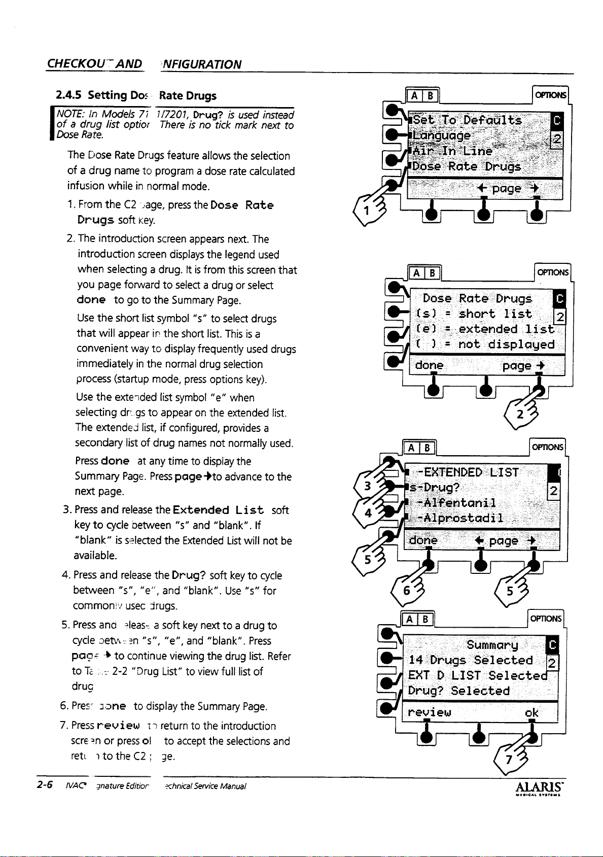
CHECKOUT
AND
‘NFIGURATION
2.4.5
NOTE:
of a drug
Dose
Setting
In
Rate.
The
Dose
of a drug
infusion
1.
From
Drugs
2.
The
introduction
when
you
done
Use
that
convenient
immediately
process
Use
selecting
The
secondary
Press
Summary
next
3.
Press
key
to
“blank”
available.
4.
Press
between
common:v
Dos.
Rate
Models
list
while
the
introduction
selecting a drug.
page
the
will
the
extended
done
page.
and
cycle
and
7i
optior
Rate
Drugs
name
to
in
normal
C2
age,
soft
key.
screen
forward
to
go
to
short
list
appear
(startup
extended
dr:.gs
is
“s”,
in
way
to
in
the
mode,
to
list,
list
of
drug
at
any
Page.
Press
release
between
selected
release
“e”,
usec
drugs.
1/7201,
There
program a dose
screen
the
symbol
list
appear
if
the
the
Drugs
Drug?
is
no
feature
pressthe
displays
to
the
display
normal
configured,
time
the
and
allows
mode.
Dose
appears
the
It
is
from
select a drug
Summary
“s”
to
short
list.
frequently
drug
press
options
symbol
names
page
Extended
“s”
Drug?
“e”
on
the
not
to
display
+to
and
“blank”.
Extended
soft
“blank”.
is
used
tick
mark
the
selection
rate
calculated
Rate
next.
The
legend
this
screen
or
select
Page.
select
drugs
This
is
used
selection
key).
when
extended
provides
normally
the
advance
List
List
will
key
to
Use
“s”
instead
next
used
that
a
drugs
list.
a
used.
to
the
soft
If
not
cycle
for
to
be
©
in
Die
e
(e)
1.1. = not
done
he
short
=
extended
:
list
displayed.
pages
list”
[>
©
-EXTENDED
E
E
+
LIST
2-6
5.
Press
and
cycle
deta:
pags + to
to
Te
:.-
drug
6.Pres: 3 っ
7.
Press
review
scre?n
rett
NAC
or
ntotheC2:
3nature
2leas- a soft
=n
“s”,
continue
2-2
“Drug
ne
to
display
1>
press
oi
Editior
key
“e”,
and
viewing
List”
to
the
return
to
to
accept
ge.
schnical
next
to a drug
“blank”.
the
drug
view
full
Summary
the
introduction
the
selections
Service
Manual
Press
list.
list
of
Page.
to
Refer
and
o-
e!
PRO
14
Drugs
EXT
D
‘Drug?
review
(©
|
Selected
LIST
Selected”
Selected
:
è
10)
_
ok.
MEDICAL
0
-
っ
SYETEMS
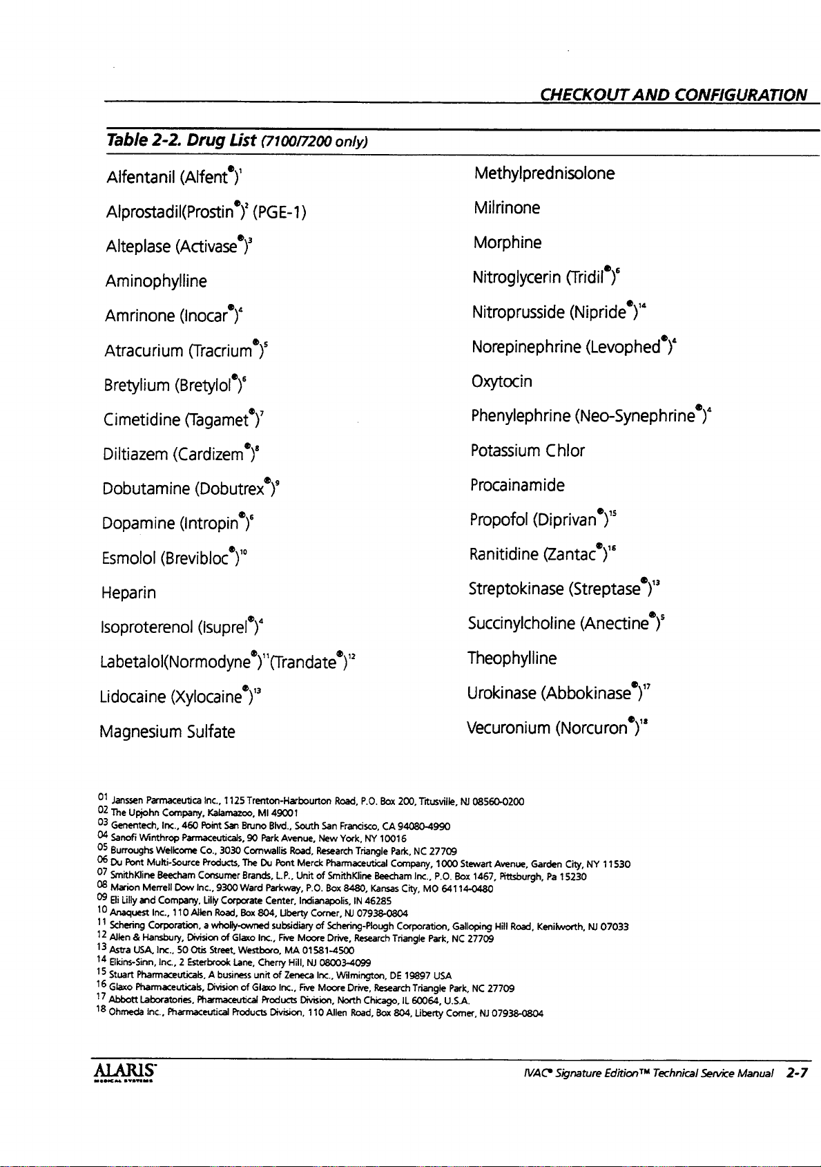
Table
Alfentanil
2-2.
Drug
(Alfent“)'
List
(7100/7200
only)
CHECKOUT
AND CONFIGURATION
Methylprednisolone
Alprostadil(Prostin“)'
Alteplase
(Activase
(PGE-1)
y
Aminophylline
Amrinone
Atracurium
Bretylium
Cimetidine
Diltiazem
Dobutamine
Dopamine
Esmolol
(Inocar“)“
(Tracrium”)'
(Bretylol“)“
(Tagamet’)’
(Cardizem“)“
(Dobutrex“)
(intropin
(Brevibloc“)"
Y
Heparin
Milrinone
Morphine
Nitroglycerin
Nitroprusside
Norepinephrine
Oxytocin
Phenylephrine
Potassium
ανν
(Nipride“)“
(Levophed’)*
(Neo-Synephrine“)“
Chlor
Procainamide
Propofol
Ranitidine
Streptokinase
(Diprivan“)"
(Zantac“)“
(Streptase
)"
Isoproterenol
(Isuprel’)*
Labetalol(Normodyne’)"(Trandate’)”
Lidocaine
Magnesium
01
Janssen
02
The
Upjohn
03
Genentech,
04
Sanofi
05
Burroughs
06
Du
Pont
07
SmithKline
08
Marion
09
Eli
Lilly
10
Anaquest
11
Schering
12
Allen 8 Hansbury,
13
Astra
14
Elkins-Sinn,
15
stuart
16
Glaxo
17
Abbott
18
Ohmeda
(Xylocaine’)”
Sulfate
Parmaceutica
Company,
inc.,
Winthrop
Welicorne
Multi-Source
Beecham
Merrell
and
Company,
Inc.,
Corporation, a wholly-owned
USA,
inc.,
Inc., 2 Esterbrook
Pharmaceuticals, A business
Pharmaceuticals,
Laboratories,
inc.,
Inc.,
1125
Trenton-Harbourton
Kalamazoo,
460
Point
San
Co.,
3030
Products,
9300
Lilly
Corporate
Road,
of
Street,
Division
Brune
90
Comwallis
The
Brands,
Ward
Box
Glaxo
Westboro,
Lane,
of
Products
Parmaceuticals,
Consumer
Dow
Inc.,
110
Allen
Division
50
Otis
Pharmaceutical
Pharmaceutical
Glaxo
MI
49001
Bivd.,
Park
Avenue,
Road,
Du
Pont
L.P.,
Parkway,
Center,
804,
Liberty
subsidiary
Inc.,
Fiwe
MA
Cherry
Hill,
unit
of
Zeneca
Inc.,
Products
Division,
Road,
P.O.
South
San
Francisco,
New
York,
Research
Merck
Unit
of
P.O.
Indianapolis,
Corner,
of
Moore
01581-4500
NJ
08003-4099
Inc.,
Five
Moore
Division,
110
NY
Triangle
Pharmaceutical
SmithKline
Box
8480,
IN
46285
NJ
07938-0804
Schering-Plough
Drive,
Research
Wilmington,
Drive,
North
Chicago,
Allen
Road,
Box
200,
CA
94080-4990
10016
Park,
NC
Company,
Beecham
Kansas
Inc.,
City,
Corporation,
Triangle
DE
19897
Research
Triangle
IL
60064,
Box
804,
Succinylcholine
Theophylline
Urokinase
Vecuronium
Titusville,
Liberty
27709
1000
P.O.
MO
64114-0480
Park,
USA
U.S.A.
Comer,
NJ
08560-0200
Stewart
Box
1467,
Galloping
NC
27709
Park,
NC
Avenue,
Pittsburgh,
Hill
Road,
27709
NJ
07938-0804
(Anectine’)’
(Abbokinase’)”
(Norcuron“)"
Garden
City,
NY
NJ
11530
07033
Pa
15230
Kenilworth,
musicas
svsvams
S
IVAC*
Signature
EditionTM
Technical
Service
Manual
2-7
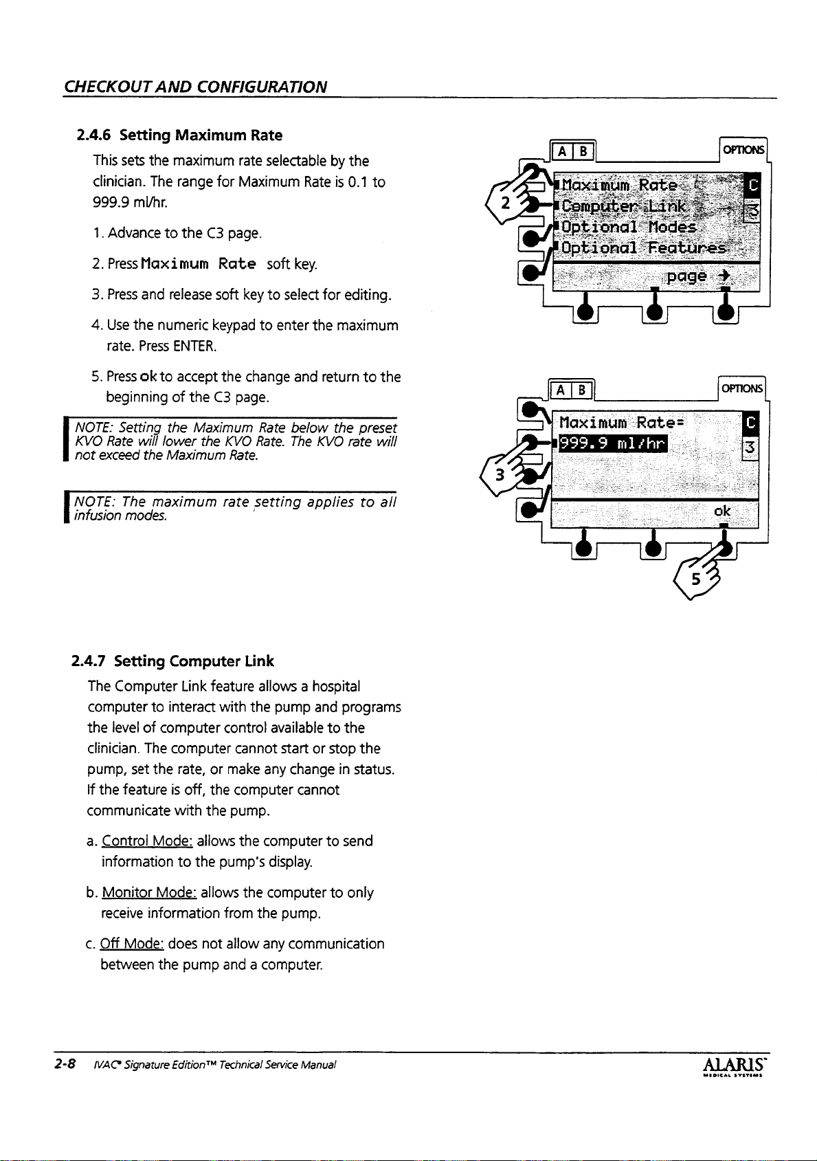
CHECKOUT
AND
CONFIGURATION
2.4.6
Setting
This
sets
clinician.
999.9
mi/hr.
1.
Advance
2.PressMaximum
3.
Press
4.
Use
the
rate.
5.
Press
beginning
|
NOTE:
KVO
not
|
N
infusion
Rate
exceed
OTE:
Setting
The
modes.
the
The
to
and
numeric
Press
ok
to
the
will
lower
the
Maximum
maximum
Maximum
maximum
range
for
the
C3
Rate
release
soft
keypad
ENTER.
accept
of
the
C3
Maximum
the
Rate
rate
Maximum
page.
key
the
change
page.
KVO
Rate.
rate
setting
selectable
Rate
soft
key.
to
select
to
enter
the
and
Rate
below
Rate.
The
KVO
applies
by
the
is
0.1
for
editing.
maximum
return
to
the
preset
rate
to
to
the
will
all
Maximum
1999.9
Вафе=
mlzhr
_
^^
2.4.7
The
computer
the
clinician.
pump,
If
communicate
a.
b.
c.
2-8
Setting
Computer
to
level
of
The
set
the
the
feature
Control
information
Monitor
receive
Off
between
IVAC®
Mode:
Mode:
information
Mode:
Signature
Computer
Link
feature
interact
computer
computer
rate,
or
is
off,
the
with
the
allows
to
the
allows
does
not
the
pump
Edition®M
Link
allows a hospital
with
the
pump
control
make
pump's
from
allow
and a computer.
Technical
available
cannot
any
computer
pump.
the
computer
display.
the
computer
the
any
Service
start
change
cannot
pump.
communication
Manual
and
or
to
to
stop
to
programs
the
the
in
status.
send
only
MEDICAL
SYSTEMS
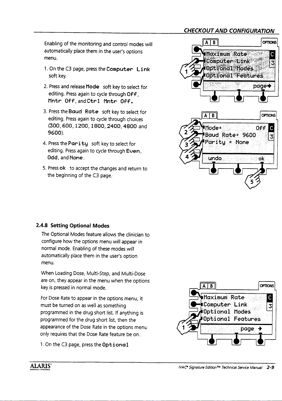
CHECKOUT
AND
CONFIGURATION
Enabling
automatically
menu.
1.
On
soft
2.
Press
editing.
Mntr
3.
Press
editing.
(300,
9600).
4.
Press
editing.
Ddd,
5.
Press
the
of
the
the
C3
page,
key.
and
release
Press
Off,
the
Baud
Press
600,
the
Parity
Press
andNone.
ok
to
beginning
monitoring
place
them
press
Mode
again
to
andCtr1
Rate
again
to
1200,
accept
again
of
the
1800,
soft
to
the
C3
and
in
the
the
Computer
soft
cycle
Mntr
soft
cycle
2400,
key
cycle
through
changes
page.
control
user's
key
to
through
Off.
key
to
through
4800
to
select
and
modes
options
Link
select
for
Off,
select
for
choices
and
for
Even,
return
to
will
Mode:
pe
18040
‘Parity = None
Rate:
9600
©
2.4.8
The
configure
normal
automatically
menu.
When
are
key
For
must
programmed
programmed
appearance
only
1.
On
MEDICAL
SYSTEMS
Setting
Optional
how
mode.
Loading
on,
they
is
pressed
Dose
Rate
be
turned
requires
the
C3
S
Optional
Modes
the
options
Enabling
place
Dose,
appear
in
normal
to
appear
on
as
in
the
drug
for
the
of
the
Dose
that
the
page,
press
Modes
feature
them
Multi-Step,
in
the
well
drug
Dose
allows
menu
of
these
in
the
menu
mode.
in
the
as
something
short
short
Rate
in
Rate
the
Optional
options
list.
the
will
appear
modes
user's
option
and
Multi-Dose
when
the
If
anything
list,
then
the
options
feature
clinician
in
will
options
menu,
the
be
it
is
menu
on.
to
Jal
Maximum
©—+Computer
IOptional
IVAC?
Optional
Signature
EditionTM
B
|
Rate
Link
Modes
Features
page
Technical
Service
+
Manual
2-9
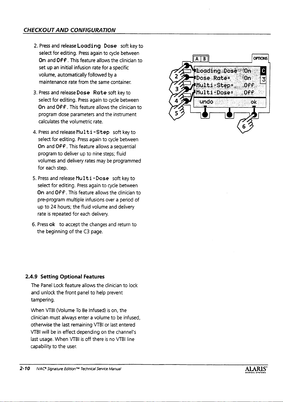
CHECKOUT
2.
Press
select
On
set
volume,
maintenance
3.
Press
select
On
program
calculates
4.
Press
select
On
program
volumes
for
AND
and
release
for
editing.
and
OFF.
up
an
initial
automatically
and
release
for
editing.
and
OF
fF.
dose
the
and
release
for
editing.
and
OF
fF.
to
deliver
and
each
step.
CONFIGURATION
Loading
Press
again
This
feature
infusion
rate
from
Dose
Press
This
feature
parameters
volumetric
Multi-Step
Press
This
feature
up
delivery
allows
rate
followed
the
same
Rate
again
allows
and
rate.
again
allows a sequential
to
nine
rates
may
Dose
to
soft
cycle
between
the
clinician
key
for a specific
by
a
container.
soft
key
to
to
cycle
between
the
clinician
the
instrument
soft
key
to
to
cycle
between
steps;
fluid
be
programmed
to
to
to
Dose
Rate
5.
Press
select
On
pre-program
up
rate
6.
Press
the
2.4.9
Setting
The
Panel
and
unlock
tampering.
When
clinician
otherwise
VTBI
will
last
usage.
capability
and
release
for
editing.
and
Off.
to
24
hours;
is
repeated
ok
to
accept
beginning
Optional
Lock
feature
the
front
VTBI
(Volume
must
always
the
last
be
in
effect
When
to
the
Multi-Dose
Press
This
feature
multiple
the
for
infusions
fluid
each
the
of
the
C3
Features
allows
panel
To
Be
enter a volume
remaining
depending
VTBI
is
off
user.
again
to
cycle
allows
over a period
volume
delivery.
changes
page.
the
clinician
to
help
prevent
Infused)
there
VTBI
on
is
or
the
is
soft
key
between
the
clinician
and
delivery
and
return
on,
the
to
be
last
entered
channel's
no
VTBI
to
to
of
to
to
lock
infused,
line
2-10
¡VAC?
Signature
Edition"*
Technical
Service
Manual
ALARIS
MEDICAL
SYSTEMS
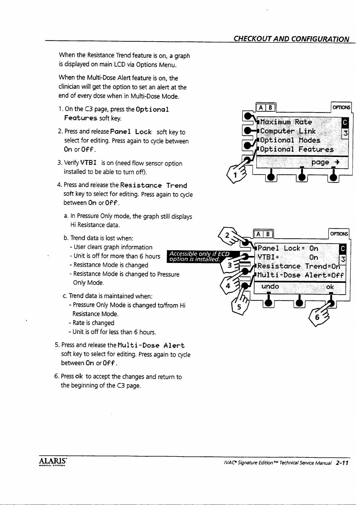
When
the
is
displayed
When
the
clinician
end
1.
2.
3.
4.
will
of
every
On
the
Features
Press
and
select
for
On
or
OFF.
Verify
YTBI
installed
Press
and
soft
key
between
Resistance
on
main
Multi-Dose
get
the
option
dose
when
C3
page,
press
soft key.
release
editing.
to
release
to
On
Panel
is
on
be
able
the
select
for
or
OFF.
Press
Trend
feature
LCD
via
Options
Alert
feature
to
in
Multi-Dose
the
Optional
Lock
again
(need
flow
to
turn
off).
Resistance
editing.
set
an
to
cycle
sensor
Press
is
on, a graph
Menu.
is
on,
the
alert
at
the
Mode.
soft
key
between
option
Trend
again
to
to
cycle
CHECKOUT
AND
CONFIGURATION
a. In
b.
c.
5.
Press
soft
between
6.
Press
the
Pressure
Hi
Resistance
Trend
data
-
User
clears
-
Unit
is
off
-
Resistance
-
Resistance
Only
Mode.
Trend
data
-
Pressure
Resistance
-
Rate
is
changed
-
Unit
is
off for
and
release
key
to
select
On
ok
to
accept
beginning
Only
mode,
data.
is
lost
graph
for
more
Mode
Mode
is
maintained
Only
Mode
Mode.
less
the
for
or
OFF.
the
of
the
the
graph
when:
information
than 6 hours
is
changed
is
changed
is
than 6 hours.
Multi-Dose
editing.
changes
C3
page.
to
when:
changed
Press
and
still
displays
Accessible
option
Pressure
to/from
Alert
again
to
return
Hi
cycle
to
only
is
installed.
if
ECD
>
Panel
Resistance
Lock=
Multi-
“unda
i
Dose:
a
On.
Trend=
Alert
:
Dr
OFF
Ok
:
IVAC
Signature
Edition™
Technical
Service
Manual
2-11
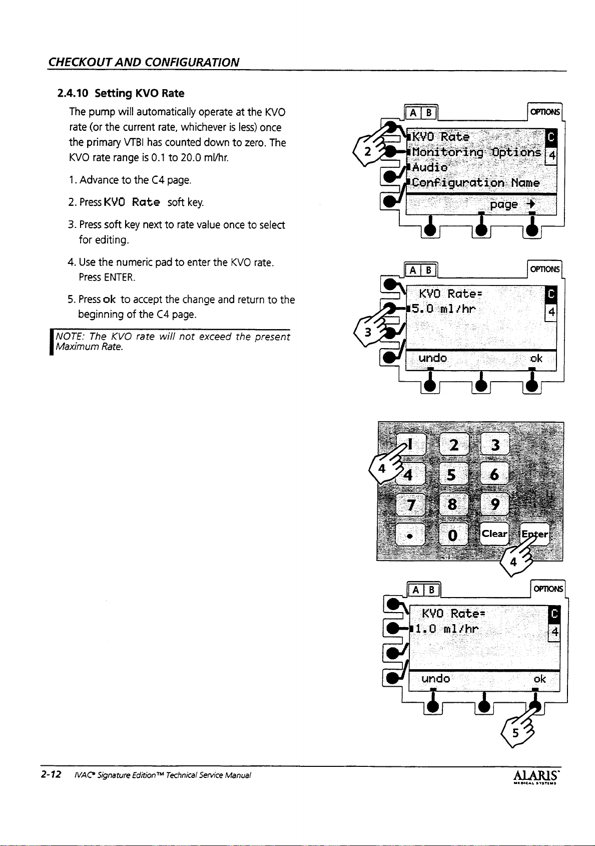
CHECKOUT
AND
CONFIGURATION
2.4.10
The
rate
the
KVO
1.
Advance
2.PressKVÜ
3.
Press
for
4.
Use
Press
5.
Press
beginning
NOTE:
Maximum
Setting
pump
will
(or
the
primary
rate
range
to
soft
editing.
the
numeric
ENTER.
ok
to
The
KVO
Rate.
KVO
Rate
automatically
current
VTBI
key
of
has
is
0.1
the
C4
Rate
next
pad
accept
the
C4
rate
rate,
counted
to
page.
soft
to
rate
to
the
page.
will
not
operate
whichever
down
20.0
ml/hr.
key.
value
once
enter
the
change
and
exceed
at
the
is
less)
to
zero.
to
KVO
return
the
KVO
once
The
select
rate.
to
the
present
]
KYO
5.
Επ]
Rate=.
ΗΝ
|
2-12
IVAC®
Signature
Edition®M
Technical
Service
Manual
MEDICAL
SYSTEMS
ON
@-11.0
ras
nlihr
e
$$

CHECKOUT
AND
CONFIGURATION
2.4.11
Setting
The
graphical
LCD)
may
will
also
The
AutoRestartPlus™
automatically
stream
.
period
message
can
number
NOTE:
clinician
turned
A
If
The
in
presented
the
1.
2.
(40
be
turned
The
presses
off,
resistance
on,
the
default
5%
increments.
value
On
the
Options
Press
and
for
editing.
Resist.
Only.
Monitoring
resistance
be
turned
turn
the
resistance
. . .
continue
occlusion
seconds).
will
appear
off
of
restarts
restart
Run/Hold,
or
if
an
alarm
alert
hospital
alert
to
the
to
meet
C4
page,
soft
release
Press
Resistance
display
on
or
feature
an
is
cleared
A
warning
for
40
(set
the
may
be
counter
if
occurs.
feature
can
set
can
level
This
is
clinician;
specific
press
the
key.
the
Mode
again
Options
(appearing
off.
Turning
alert
infusion
during
.
seconds.
restarts
set
is
reset
the
may
the
desired
set
be
the
initial
the
clinician
application
Monitoring
to
cycle
feature
allows
κ.
if
the
tone
to
from
1
whenever
pump
be
turned
from
value
soft
key
between
and
Pressure
the
the
a
and
The
zero),
or
alert
needs.
in
the
Main
display
off.
pump
off
to
down-
“re-check”
.
display
feature
or
to
the
9.
the
channel
on
or
is
off.
level.
100%
to
5
may
reset
to
select
Hi
NOTE:
め
NOTE:
when:
to
line
NOTE:
resistance
beginning
seconds,
NOTE:
thirty
off
when
threshold
Resistance
Clear
iS
Resistance
1)
Run/Hold
start,
2)
message
Checking
and
off
Resistance
seconds,
for
6
seconds).
the
resistance
or
1
trend
pressed,
measurement
is
Dose
ends
appears.
line
upstream
and
a
flashing
for
6
seconds).
alert
with
a
Nurse
at
100%
[AIB]
Ton
Monitoring.
Audio
graph
2)
Pump
is
pressed
in
popup
measurement
even
to
Multi-Dose
alert
applies
occlusion
popup
No
nurse
will
give
display
call
activated.
when
e
Rat
|
vi
@
put
an
checking
data
off
for
is
restarted
on
mode,
with
display
call
alarm
(on
is
above
Options
“page
a
Page
is
lost
when:
more
than
hold
to
one
at
and
again
3)
Checking
pressure,
tone
at
{on
for
activation.
tone
4
seconds,
This
occurs
the
every
alert
for
line.
OPTIONS
TT
E
~
+
2.
6
0%
the
4
4
È
:
3.
Press
select
On
NOTE:
automatically
4.
Press
the
restarts
9,
then
5.
Press
between
keypad
ENTER.
6.
Press
the
MEDICAL
SYSTEMS
-
and
release
for
editing.
and
OFF.
If
display
turned
be
and
release
numeric
the
ok
from
press
Alert
On
to
enter
The
value
to
accept
keypad
O
ENTER.
and
beginning
the
Press
is
off,
off.
the
(which
soft
OFF.
the
will
the
of
the
Display
again
the
alert
Restarts
to
enter
turns
key.
Press
If
on,
desired
C4
alert
round
changes
page.
to
to
the
the
feature
again
use
the
and
soft
key
cycle
between
feature
soft
number
to
the
numeric
%.
Press
nearest
return
to
will
key.
of
off)
to
cycle
5%.
to
Use
IVAC
lAler
Signature
Edition™
Technical
Service
Manual
2-13

CHECKOUT
AND
CONFIGURATION
2.4.12
Setting
The
volume
audio
volume
example;
institution,
A
transition
completion
mode,
mode,
loading-dose
approximately:
i=
1.On
2.
Press
select
LowMedHi,MedHi,
3.
Press
editing.
Off.
4.
Press
the
“Low”
dose
and
75
cB.
the
C4
and
for
the
Press
ok
beginning
Audio
settings
is
therefore
tone,
of a secondary
beginning
completion
mode.
Low = 65
menu,
release
editing.
Trans.
to
accept
Volume
determine
available
may
be
you
if
enabled,
and
of a loading
The
press the
the
Volumes
Press
Tone
again
to
the
of
the
C4
which
to
the
too
low
would
will
VTBI,
ending
speaker
dB,
Med = 70
Audio
again
to
orHi.
soft
cycle
between
changes
page.
range
clinician.
for
choose
sound
step
volumes
cycle
key
and
For
your
“Med
upon
in
multi-step
in
multi-dose
dose
in
are
dB,
and
soft
key.
soft
key
between
to
select
On
and
return
of
Hi”.
to
to
for
2.4.13
The
lower
displayed,
The
identify
location,
alpha/numeric
Intensive
2400.
2-14
IVAC
Setting
ID
characters
LCD
configuration
Configuration
Label)
entered
display.
even
when
the
instrument's
or
reference
name,
Care
Unit),
Signature
EditionTM
This
name
Name
here
will
be
electronic
the
pump
is
can
be
used
configuration,
number.
examples
ICU
Technical
It
is a 4
are:
(Intensive
Service
(Instrument
shown
label
is
normally
off.
to
uniquely
hospital
character
PICU
(Pediatric
Care
Unit),
Manual
in
the
or
MEOICAL
SYSTEMS

NOTE:
to
configuration
Configuration
reflection
NOTE:
the
efore
Refer
explanation.
NOTE:
use
You
the
configuration
of
1.
On
the
Name
2.
Press
and
position
changed.
3.
Press
and
with
the
highlight
4.
Press
enter.
programmed
necessary.
5.
Press
ok
he
beginning
the
beginning
If
you
name,
space
the
turning
to
Section
Must
(-)
have
symbol
will
see
mode.
Mode”
your
instrument's
C4
menu,
soft
key.
release
the
highlight
release
rows
the
character
in
to
accept
of
of
have
changed
pump
off
or
2.5.2
4
characters
to
a
4
digit
name
Refer
to
.
This
code
press
Conf
on
the
character
A
to
M,
N
you
Up
to
four
this
way.
the
changes
the
CA
page.
the
C4
the
will
display
proceeding
“Pop-Up
fill
in
any
alpha/numeric
upon
Section
is
only
configuration.
the
Configuration
ig.
Name
the
character
soft
to
Z,
or
want.
characters
Repeat
and
code
entering
2.4.1
“Entering
a
hexadecimal
soft
to
keys
0
to
_
to
can
steps
2,3,4
return
page
configuration
the
option
to
the
Displays”
in
configuration
open
Character.
to
rename
teach
for
but
next
key
to
be
aligned
be
as
to
not
mode.
further
name,
CHECKOUT
1
2729-14
GR).
AND
Configuration
6
A|B
Config.
CONFIGURATION
16-
Name=fivAC
BCDEFGHBJKLM.
NOPORSTUVUXYZ
3
10123456789...
.
undo
i
enter
©
à
è,
*
—
—
Ар.
ok
.
a:
2.5
Transferring
Once
technical
transferred
pump
pump
NOTE:
transferred.
periodic
will
mode
Connect
cable
P/N
MEDICAL
SYSTEMS
a
pump
and
to
is
referred
is
referred
Only
the
The
maintenance
be
not
a
standard
(also
available
133450)
to
Settings
has
been
programmed
clinical
other
transferred.
needs,
pumps.
to
as
the
to
as
the
configuration
instrument
settings
9-pin
Null
from
ALARIS
the
RS-232
to
Another
to
the
settings
The
programmed
“Teacher”
“Learner”.
ID
from
Modem
ports
and
settings
number
the
diagnostics
Medical
on
the
Pump
meet
can
be
the
will
and
RS-232
Systems,
pumps.
other
be
the
IVAC
Signature
Edition™
Technical
Service
Manual
2-15

CHECKOUT
2.5.1
Teacher/Learner
1.
Access
“teacher”
advance
AND
the
CONFIGURATION
Configuration
and
“learner”
to
page
C5.
Pump
Procedure
Mode
instruments
for
both
and
2.
Learn
3.
Press
“Teacher”
The
transfer
transfer
[sore
next
pump.
|
revision
pumps
70004).
Press
and
release
“Teacher”
pumps
Repeatallows
The
level
are
instrument
soft
and
release
instrument.
will
is
complete,
was
successful
Learn/Teach
is
not
not
the
the
key
of
“Learner”
the
display
the
Downloadi
then
or
you
function
same
same
Teach
and
start
they
unsuccessful.
to
on
model
soft
press
and
instrument.
soft
will
indicate
re-attempt
will
both
pumps
(ie.,
710x/720x
key
of
release
key
of
ng
until
or
teach
not
work
or
the
the
if
the
if
the
the
the
if
the
to
2.5.2
2-16
Pop-Up
The
pop-up
attempts
teach
accessing a configured
configuration
instrument's
configuration
instruments
pope
°
IVAC®
screens
to
turn
mode
after
configuration
but
mens
Signature
Displays
appear
off
the
changing
name.
name,
If
you
with
different
you
ask
Edition"
when
instrument
the
configuration
item) but
you
change
and
not
may
have
configurations.
want
you
if
Technical
Service
the
user
or
execute
not
changing
the
the
similarly
rename
to
Manual
the
(or
the
named
The
the
E
has
O
@—
e
el
Tonfi
been
Press
to:
cancel
de
guratie
teach
keep:
teach
on
changed.
key
name
IVAC.
rename
ALARIS
MEDICAL
SYSTEMS

CHECKOUT
AND
CONFIGURATION
Duplicate
Table
2-3.
*Instrument
Config
(Instr
Location
Language
Air-in-Line:
Maximum
Computer
Optional
Optional
Resistance
Multi-Dose
KVO
Rate
Monitoring
Audio:
*PM
Reminder
*PM
Interval
*Accessed
the
following
Record
ID
Name
Label)
Threshold
Rateml/hr
Link:
Baud
Modes:
Loading
Dose
Multi-Step
Multi-Dose
Features:
Panel
Options:
Display
Restarts
Volume
Trans.
through
of
Configured
#
Reset
Mode
Rate
Parity
Dose
Rate
Lock
Trend
Alert
ml/hr
Mode
Alert
Tone
Diagnostic
table
for
additional
Instruments
Serial
mMhr
ml/hr
|
Mode.
Refer
entries.
#
to
Serial
Section
mi/hr
ml/hr
6.4.1
#
Serial
ml/hr
mí/hr
“Entering
Diagnostics
#
Serial
ml/hr
ml/hr
#
Mode”
Serial
#
ul
ml/hr
ml/hr
MEDICAL
nyntemA
IVAC®
Signature
Edition®M
Technical
Service
Manual
2-17
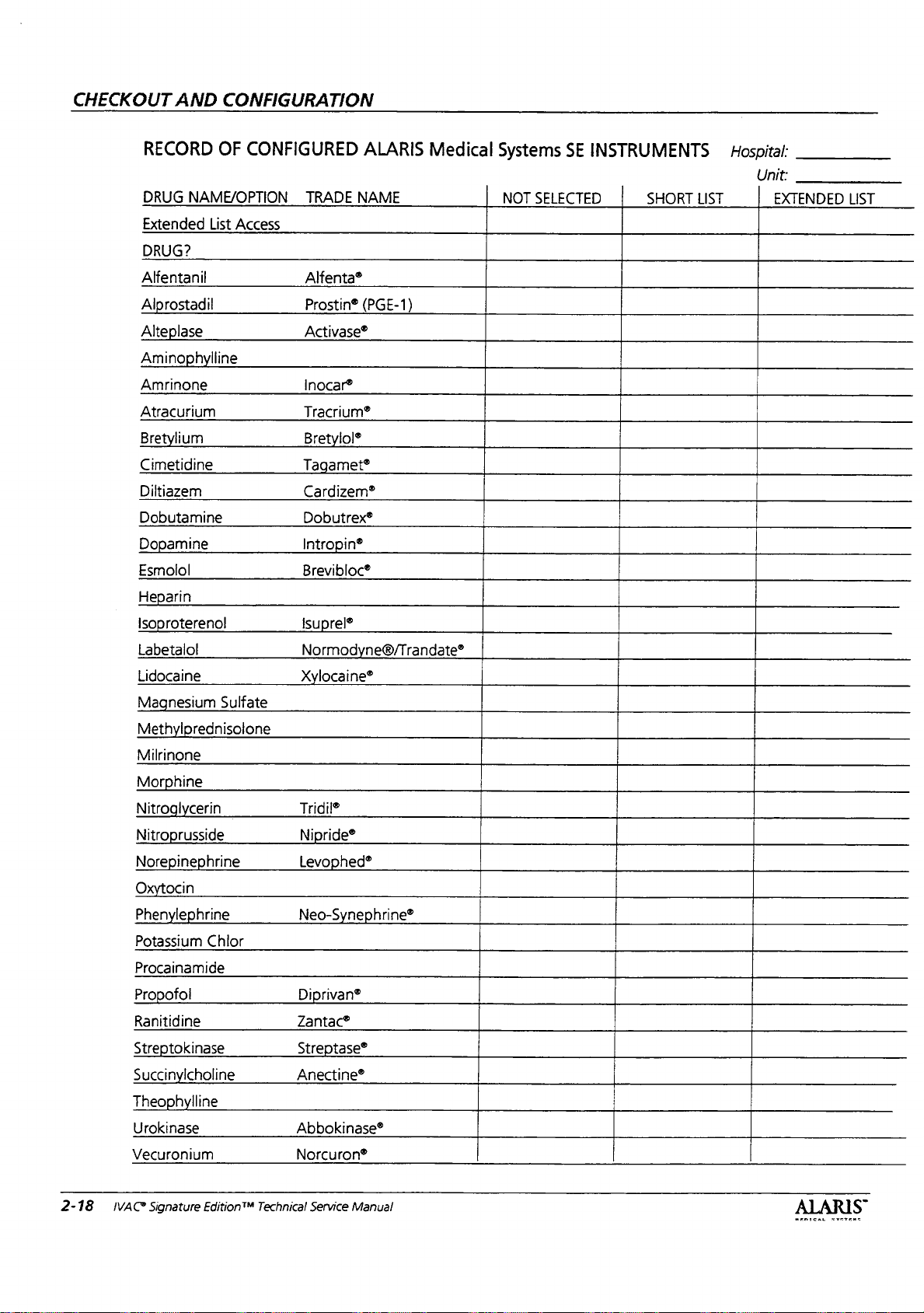
CHECKOUT
AND
CONFIGURATION
RECORD
DRUG
NAME/OPTION
Extended
DRUG?
Alfentanil
Ami
Amrinone
Atracurium
Bretylium
Cimetidine
Diltiazem
Dobutamine
Esmolol
H
Labetalol
Lidocaine
rostadil
mine
in
roterenol
nesium
Milrinone
ine
OF
CONFIGURED
List
Access
line
Sulfate
nisolone
TRADE
Alfenta®
Prostin®
Activase®
Inocar®
Tracrium®
B
T
Cardizem®
Dobutrex®
|
Brevibloc®
Isu
No
x
Tridil®
Ni
ALARIS
NAME
met®
in®
e®/Tran
ine®
Medical
E-1
Systems
NOT
SELECTED
SE
INSTRUMENTS
SHORT
Hospital:
LIST
Unit:
EXTENDED
LIST
2-18
Potassium
Procainamide
Ranitidine
S
tokinase
Succi
Urokinase
Vecuronium
IVAC?
Signature
inephrine
in
hrine
Chlor
ine
line
Edition™
Technical
Neo-S
Diprivan®
Zantac®
S
Anectine®
Abbokinase®
Norcuron®
Service
tase®
Manual
hrine®
ALARIS
MEDICAL
yarra

Chapter
3
—
PREVENTIVE
MAINTENANCE
WARNING:
preventive
improper
instrument
Failure
maintenance
operation.
to
perform
inspections
regular
may
result
and
in
3.1
Introduction
To
ensure
condition,
inspections
covered
ALARIS
before
Use
Table
completion
These
inspections
indicated
The
preventive
recommended
performed
Systems
reminder
feature
interval
intended
also
requirements,
Medical
the
pump
regular
under
Medical
each
3-1
of
by
in
requirements
will
has
been
or
has
Systems
and
are
required.
any
contract
Systems
use
of
the
“PM
Inspections”
preventive
should
qualified
maintenance
at
a
one
accordance
after
occur
changed
been
disabled.
complement
to
and
are
warranty.
remains
technician
and
not
in
preventive
Regular
or
agreement
and
must
instrument
to
maintenance
be
performed
or
inspections
year
interval
with
ALARIS
guidelines.
weeks,
52
to
select
These
the
covered
good
operating
maintenance
inspections
offered
be
performed
by
the
user.
record
the
inspections.
yearly
biomedical
listed
and
should
Medical
A
maintenance
the
unless
a
different
inspections
JCAHO
of
intent
by
the
ALARIS
are
not
by
or
as
engineer.
are
be
time
are
In
the
United
obtained
performance
inspections.
3.2
Storage
3.2.1
Storage
The
pump
power.
when
the
after
storage,
of
three
When
temporarily
connect
battery
IVAC®
States,
from
of
and
may
It
will
automatically
voltage
connect
(3)
hours
it
to
AC
when
needed.
Signature
a
service
ALARIS
all
required
Medical
Cleaning
be
stored
gets
too
it
to
before
taking
power
to
Edition™
agreement
Systems
preventive
without
low.
AC
placing
instrument
ensure
Technical
connection
disconnect
To
reuse
power
it
back
a
fully
Service
may
for
the
maintenance
to
the
battery
the
pump
for
a
minimum
into
service.
out
of
service,
charged
Manual
be
AC
3-7
*
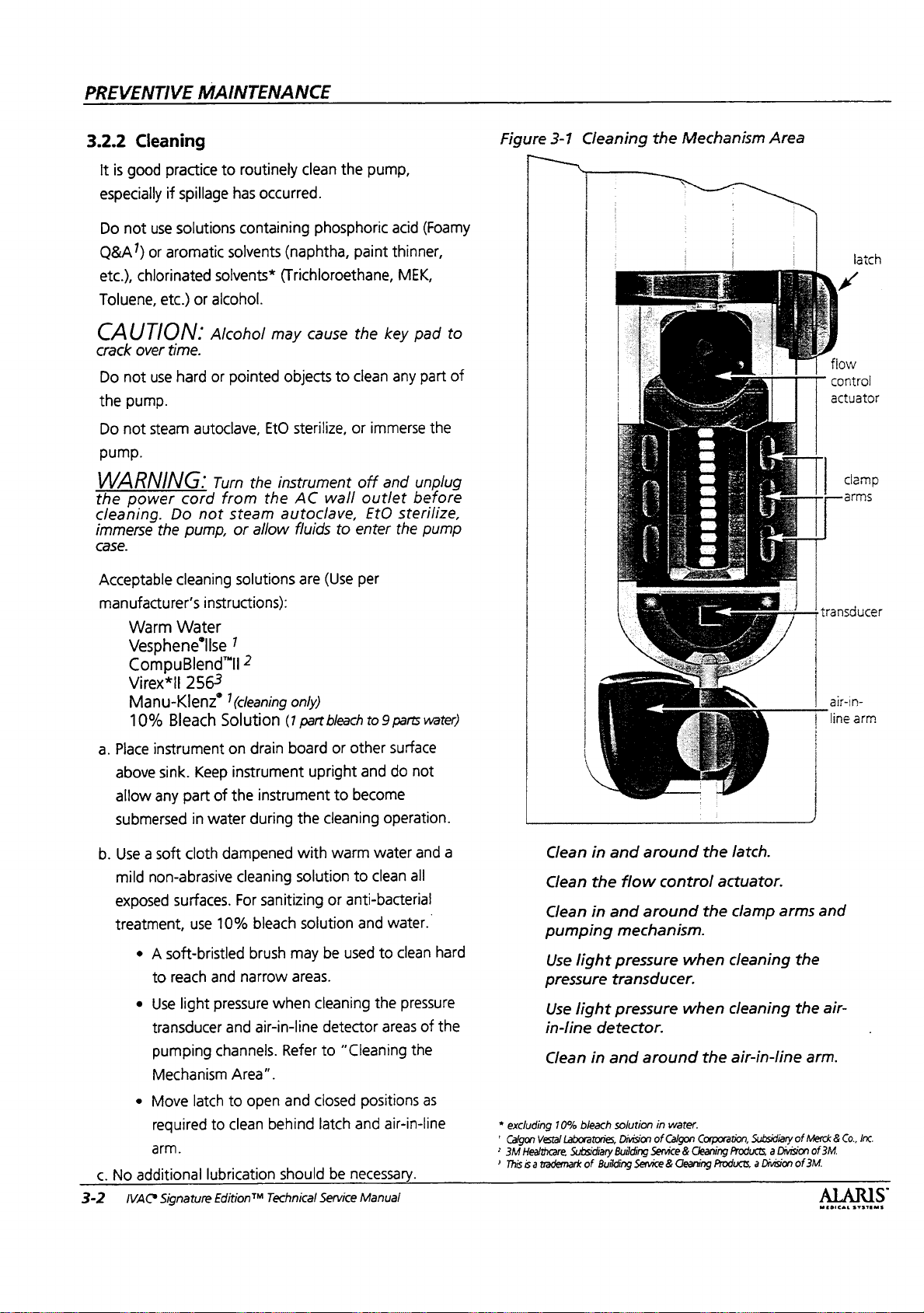
PREVENTIVE
MAINTENANCE
3.2.2
Cleaning
It
is
good
practice
especially
Do
Q&A")
etc.),
Toluene,
CAUTION:
crack
Do
the
Do
pump.
WARNING:
the
cleaning.
immerse
case.
Acceptable
manufacturer's
if
not
use
solutions
or
aromatic
chlorinated
etc.)
over
time.
not
use
hard
pump.
not
steam
power
Do
the
cleaning
Warm
Water
Vesphene'lise
CompuBlend”li
Virex*
Il
Manu-Klenz?
10%
Bleach
to
routinely
spillage
cord
pump,
has
containing
solvents
solvents*
or
alcohol.
Alcohol
or
pointed
autoclave,
Turn
the
from
not
steam
or
allow
solutions
instructions):
?
2
2563
(cleaning
Solution
clean
the
occurred.
phosphoric
(naphtha,
(Trichloroethane,
may
cause
objects
EtO
instrument
the
autoclave,
(7
to
sterilize,
AC
wall
fluids
to
are
(Use
only)
part
bleach
pump,
acid
paint
thinner,
MEK,
the
key
clean
any
or
immerse
off
and
outlet
EtO
sterilize,
enter
the
per
to 9 parts
(Foarny
pad
to
part
of
the
unplug
before
pump
water)
Figure
「
3-1
Cleaning
the
Mechanism
Area
M
E
er
T”
-
transducer
|_air-in-
latch
flow
control
actuator
clamp
arms
line
arm
a.
Place
above
allow
submersed
b.
Use a soft
mild
exposed
treatment,
c.
No
3-2
IVAC*
instrument
sink.
any
non-abrasive
surfaces.
e A soft-bristled
to
reach
e
Use
light
transducer
pumping
Mechanism
e
Move
required
arm.
additional
Signature
on
Keep
instrument
part
of
the
in
water
cloth
dampened
cleaning
For
use
10%
and
pressure
and
channels.
Area”.
latch
to
to
clean
lubrication
EditionTM
drain
instrument
during
bleach
brush
narrow
air-in-line
open
board
or
upright
the
cleaning
with
warm
solution
sanitizing
or
solution
may
be
areas.
when
cleaning
detector
Refer
to
and
closed
behind
Technical
latch
should
Service
be
other
surface
and
do
not
to
become
operation.
water
and
to
clean
all
anti-bacterial
and
water.
used
to
clean
the
pressure
areas
of
“Cleaning
positions
and
necessary.
Manual
the
as
air-in-line
a
hard
the
Clean
in
and
Clean
the
flow
Clean
in
and
*
excluding
’
Calgon
2
3M
Healthcare,
?
This
is a trademark
pumping
Use
pressure transducer.
Use
in-line
Clean
10%
Vestal
Laboratories,
Subsidiary
mechanism.
light
pressure
light
pressure
detector.
in
and
bleach
solution
Building
of
Building
Division
around
around
around
in
of
Service © Cleaning
Service & Cleaning
the
control
the
when
when
the
water.
Calgon
Corporation,
latch.
actuator.
clamp
arms
cleaning
cleaning
air-in-line
Products, a Division
Products, a Division
the
the
Subsidiary
of
of
and
air-
arm.
Merck & Co.,
of
3M.
Inc.
3M.
ALARIS
MEDICAL
SYSTEMS
3.3
Preventive
A
message
which
preventive
Section
Interval”
3.3.1
Regular
Maintenance
can
be
set
through
automatically reminds
maintenance
6.4.2
“Setting
for
setting
Inspection
inspections
Preventive
the
inspection
Inspections
the
diagnostics
the
user
when
are
due.
Maintenance
interval.
mode
Refer
to
Keypad
Check
fingernails
inspection,
performs
“Testing
Mechanism
membrane
and
pens.
be
sure
its
proper
Switches”.
PREVENTIVE
switches
to
function.
for
During
check
the
that
Refer
MAINTENANCE
damage;
course
each
of
switch
to
Section
e.g.,
the
from
6.4.15
Regular
damage
procedure
Section
usage
of
covered
ALARIS
the
user.
Case
Examine
should
be
especially
solution
sensor,
Check
pressure
that
Mounting
Pole
mounting
functioning.
or
stand,
examine
inspections
and
cleanliness,
described
of
the
Directions
the
instrument.
under
any
Medical
the
deposits
unit
clean
near
labels
Systems
for
and
moving
on
transducer,
and
Bracket
bracket
If
the
instrument
examine
the
pole
the
and
consist
of a visual
and
in
the
Start
For
Use
Regular
contract
or
and
overall
condition.
free
from
parts.
Also
accessible
and
markings
should
condition
stand.
inspection
performing
Up
Sequence
manual
inspections
agreement
must
be
performed
The
IV
solution
check
areas
of
air-in-line
latch
mechanism.
are
legible.
be
secure
is
mounted
of
the
mount.
the
before
are
offered
case
residue,
for
dried
and
on a pole
Also,
for
each
not
by
by
Clean
have
a.
The
b.
The
are
c.
Proper
followers
d.
Air-in-line
closed
e.
Fluid
3.3.2
Functional
a.
Turn
that
b.
Set
c.
Press
and
“air
any
surfaces
accumulated.
mechanism
cam
followers
free
of
foreign
operation
should
arm
moves
position.
Control
Actuator
Test
instrument
it
“beeps”
infusion
the
rate
in
line”
and
rate
RUN/HOLD
and
VTBI # 0
messages.
where
Verify
seal
is
are
matter.
of
latching
retract
smoothly
on
without
red
to
460
switch
to
solution
that:
not
torn
or
not
broken
mechanism.
and
extend
from
rotates
180°.
set
installed.
alarm
light
ml/hr
and
with
the
cause a “set
or
obstructions
worn.
or
cracked
Cam
smoothly.
opened
Verify
flashes.
VTBI
to
100
latch
closed,
out”
and
and
to
ml.
Power
Examine
a.
Signs
damaged,
b.
Integrity
wiggle
secure.
entire
c.
Appropriate
has
d.
Strain
of
the
Cord
Assembly
the
power
of
damage,
replace
of
hospital
the
biades
If
any
cord.
tension
electrical
reliefs.
line
cord.
cord
assembly
cuts
or
the
entire
grade
to
determine
damage
is
and
receptacles
Examine
Be
the
sure
they
for:
deformities
cord.
power
plug.
that
suspected,
connection
for
accessories.
strain
reliefs
hold
the
in
the
Attempt
they
are
replace
if
the
IV
at
both
cord
securely.
cord.
the
pole
ends
If
to
d.
Open
e.
Install
f.
Verify
open”
g.
Close
the
h.
Perform
1.
2.
3.
the
latch.
primed
the
pump
messages.
the
latch
setup page.
upstream
Verify
the
With
the
the
primary
Press
the
infusion.
IVAC®
Signature
administration
displays
and
“air
verify
occlusion
infusion
pump
VTBI
RUN/HOLD
rate
on
hold,
is
set
to
switch
EditiontM
Technical
the
test
is
set
or
100.
set
in
with
line”
and
display
returns
as
follows:
to
460
at
start-up,
to
begin
Service
latch
“latch
ml/hr.
verify
the
Manual
open.
to
3-3
PREVENTIVE
MAINTENANCE
i.
3.3.3
a.
4.
Clamp
upstream
an
running,
UPSTREAM
5.
Press
and
6.
Remove
7.
Press
The
Perform
1.
Continue
2.
Verify
just
below
3.
Allow
DOWNSTREAM
4.
Press
and
put
5.
Release
6.
Press
The
alarm
Flow
Turn
the
primed
and
off
IV
alarms,
within
the
RUN/HOLD
put
the
pump
or
open
the
RUN/HOLD
alarm
should
downstream
pumping
rate
is
set
the
pump
to
the
RUN/HOLD
the
pump
or
open
the
RUN/HOLD
should
Stop
Test
power
off
loaded
line
just
above
and
60
Verify
displays
seconds.
occlusion.
switch
on
hold.
the
clamp
switch
not
reoccur.
occlusion
from
to
460
ml/hr.
pump.
run
until
within
60
switch
on
hold.
clamp.
switch
not
reoccur.
with
the
in
the
instrument.
pump
to
simulate
stops
pump
the
OCCLUSION
to
silence
on
the
to
resume
test
above
step.
Clamp
it
alarms
seconds.
to
silence
to
resume
administration
the
line.
infusion.
as
follows:
off
OCCLUSION
the
infusion.
set
alarm
the
alarm
set
|
NOTE:
a.
b.
c.
d.
e.
f.
9.
h.
i.
j.
k.
Do
not
Fill
the
solution
Take a 70
AccuSlide™
solution
Open
AccuSlide
particular
expelled
Connect
three-way
Load
the
Verify
that
|
drip
the
Plug
the
outlet.
Set
stopcock
Press
channel’s
Set
the
primary
VTBI
to
20
Press
the
infusion.
tubing
Press
and
the
use
70RCS
more
container
RCS
rate
clamp,
container.
. .
clamp
attention
from
the
stopcock.
to
the
set.
output
set.
there
is
no
chamber.
instrument
ml.
channel's
Run
burette
channel’s
into a properly
to
output
POWER
infusion
RUN/HOLD
infusion
are
RUN/HOLD
than
40
times.
with
clean
calibration
then
and
ensure
Close
of
the
fluid
to
switch
rate
set
insert
the
prime
that
the
set
to
flow
a
Class
to
to
400
to
for
one
minute,
fully
primed.
to
tap
water.
and
close
spike
into
set.
Pay
all
air
is
AccuSlide
one
side
or
drops
falling
grounded
A
or
B
burette.
turn
channel
mi/hr.
Set
start
the
primary
or
until
stop
infusion.
the
the
clamp.
of
the
AC
on.
the
in
3.3.4
NOTE:
varied
Systems
check
samples
though
3-4
b.
With
container
verify
c.
Remove
set.
Rate
Refer
to
Test”.
Due
during
does
rate
and
the
IVAC
all
tubing
two
that
no
set.
Verify
Accuracy
Figure
3-2
to
the
Dynamic
operation.
not
recommend
accuracy.
may
cause
instrument
Signature
Edition"
clamps
or
fluid
more
flows
that
open
feet
out
no
Verification
“Setup
Generally,
is
accurate.
for
Monitoring
For
this
using
these
the
results
Technical
and
the
above
of
the
fluid
flows
Test
Rate
Verification
feature,
reason,
ALARIS
automatic
devices
to
be
Service
Manual
fluid
the
device,
set.
out
of
the
Medical
testers
collect
incorrect
the
rate
is
to
small
even
|.
Adjust
container
30”
and
bottle
drip
administration
NOTE:
You
level
of
burette.
m.
Adjust
the
n.
Verify
VTBI
the
between
the
fluid
with
chamber
may
|
the
zero
mark
.
primary
to
40
height
of
the
instrument
as
necessary
the
level
unvented
(unvented
set).
need
to
| | | |
fluid
on
ーー
infusion
to
attain
middle
in
the
of
container
administration
bottle
run
instrument
level
so
the
the
burette.
rate
the
meniscus
.
is
with
to
400
and/or
head
pump
(bag
set)
vented
prime
ml/hr.
ml.
height
mechanism
or
or
line
is
level
Reset
MIDICAL
fluid
of
vented
the
to
“0”
with
the
SYETEMS

o.
Press
infusion.
p.
The
deliver
pump
q.
Verify
(5%).
r.
If
1.
for
calibration
SystemsTechnical
2.
Figure
3-2
the
channel's
pump
will
40
ml,
within 1 second
the
volume
rate
accuracy
Ensure
more
Set
70RCS
than
stopcock
Setup
procedure
for
RUN/HOLD
run
approximately
then
go
into
KVO
of
KVO
collected
verification
Rate
40
runs.
Support.
to
drain
Rate
fails:
Cal Set
Refer
or
call
into
Verification
to
start
360
mode.
operation.
is
40.0
mi + 2.0
has
not
to
Chapter 5 for
ALARIS
Medical
receptacle.
Test
the
primary
seconds
Stop
the
mi
been
used
:
to
rate
3.3.5
Pressure
a.
Place
instrurnent
and
connect
b.
Connect
reservoir
Figure
c.
install a pressure
instrument.
d.
Enter
Diagnostics
top
soft
soft
key
to
Section
e.
Advance
five
times.
Calibration
to
pressure
to
pressure
3-3
“Pressure
key,
then
when
6.4.1
to
D6
PREVENTIVE
on
bench
or
AC
power.
meter,
cal
Mode
diagnostics
“Entering
screen
hand
calibration
Test
Setup”.
set
(70ISS)
by
pressing
turn
instrument
display
Diagnostics
by
pressing
MAINTENANCE
other
flat
surface
pump,
set.
Refer
into
the
and
on
appears.
page
and
to
holding
and
release
Refer
Mode”.
soft
key
30
+2
inches
70RCS
Rate
Cal
^
Instrument
Stand
Set
MEDICAL
SYSTEMS
IVAC®
Signature
Edition™
Technical
Service
Manual
3-5

PREVENTIVE
f.
Select
MAINTENANCE
Cal
Pressure
(A
or B for
dual
channel).
3.3.7
Ground
Resistance
Test
g.
Allow 1 hour
h.
Perform
1.
2.
3.
4.
j.
Set
-
-
-
3.3.6
Ground
soft
With
no
soft
key.
Apply
500
Press
the
Remove
sensor
Verify
say
Instali
170.
Verify
mmHg
will
calibration
set
check/calibration
both 0 mmHg
“pass”.
set
sensor
range
not
“soft
Current
Use a BIO-TEK®*
measure
electrical
proper
must
polarity.
the
ground
safety
measurement
be < 100
warmup.
pressure
pressure
500
and
applied,
mmHg
(+1
mmHg
and
pressure
close
reading
without
cal,”
procedure
Leakage
Model
leakage
tester's
HA
operation
technigue.
for
normal
calibration:
press
the0
mmHg)
and 500
latch.
is
set
see the
in
of
pressure.
soft
key.
from
pump.
verification:
mmHg
Verify
reading
in
the
-30
to
installed..
hard
pressure
Chapter
5.
Test
260
or
equivalent
current.
and
Refer
manual
Leakage
reversed
|
mmHg
readings
over
'
+80
If
the
pump
to
to
the
for
the
current
line
,
Use a BIO-TEK
resistance
from
the
for
the
power
cover
on
operation
measurement
must
be < 0.10Q.
resistance
connector
CAUTION:
probe
to
pressure
3.3.8
Battery
a.
Initiate a battery
1.
Disconnecting
switch
2.
If
software
the
Mode).
rated
b.
Leave
cycle.
3.3.9
Reset
Model
testing
the
the
manuals
from
must
equipment)
AC
power
cord
chassis.
technique.
For
AC
be < 0.100.
Do
not
transducer.
Refresh
for 5 seconds
is
rated
capacity
Once
cap
back
connected
Time
260
(or
plug
strap
or
Refer
for
proper
The
Models
power
connect
Cycle
refresh
the
battery,
and
2.02
or
for
“ok”
is
to
1.3
AH.
to
AC
for
equivalent
to
measure
ground
the
screw
to
the
test
setup
resistance
7101/7201,
plug
ground
ground
cycle
by:
pressing
reconnect
higher,
battery
pressed,
24
enter
hours
ground
resistance
pin
to
for
the
equipment
and
measured
measure
pin
to
resistance
ON/OFF
battery.
0.0
(in
Diagnostics
cycle
will
to
complete
the
screw
battery
PEC
AH
in
start.
Set
a.
Enter
Figure
3-6 | IVAC*
3-3
Pressure
Signature
Test
Instrument
Edition™
Setup
Stand
Technical
Service
Manual
b.
72
Series
^
Se
reference.
NOTE:
not a true
not
be
3.3.10
Enter
PM
soft
*
Diagnostic
Reset
Clock
real
affectted
Reset
Diagnostic
Setup
key.
BIO-TEK®
hours
(See
will
time
PM
and
instruments,
Mode
and
minutes
Setting
lose
about 3 minutes
clock.
Once
or
adjusted.
Due
Mode
reset
PM
Inc.
and
Time
reset,
and
Due
advance
as
needed
in
Diagnostics
per
month
the
previous
go
to
D2
page.
by
pressing
from
to
D2
time
section)
since
loop
Access
lower
page.
it is
will
left
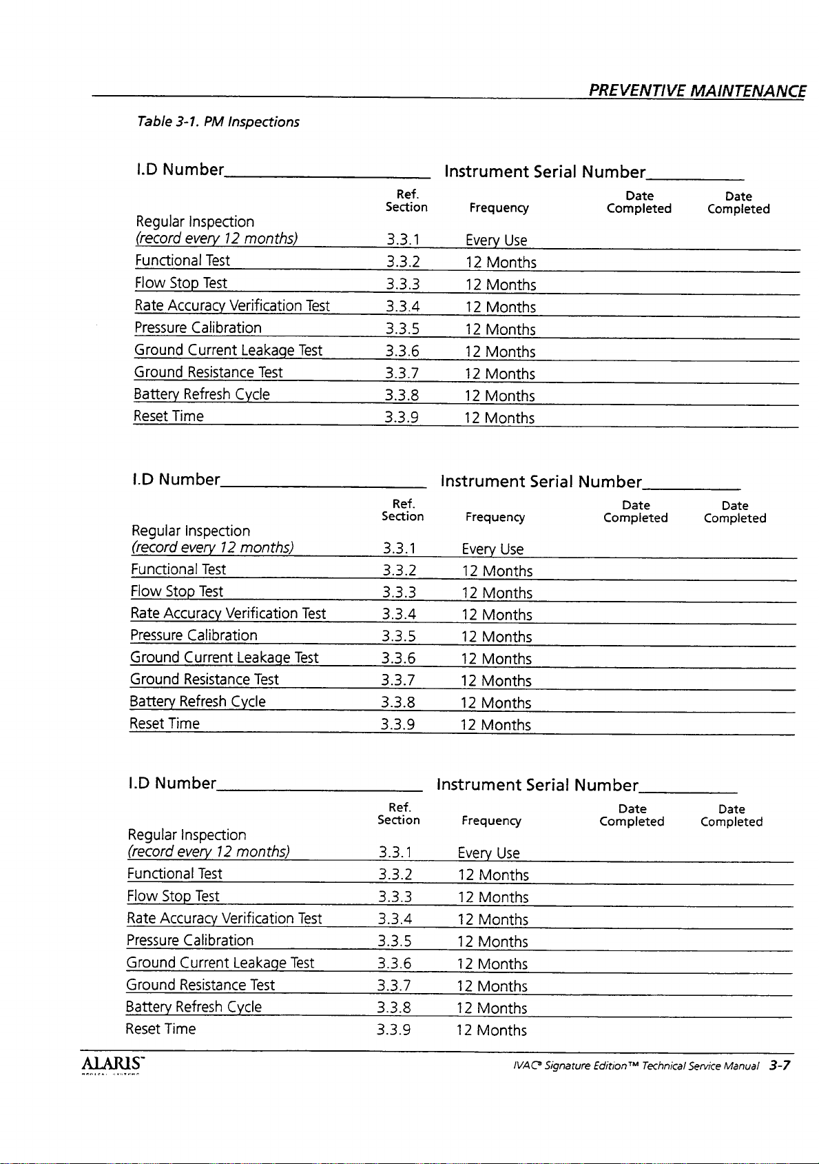
Table
3-1.
I.D
Number
Regular
(record
Functional
Flow
Rate
Pressure
Ground
Ground
Battery
Reset
I.D
Regular
(record
Functional
Flow
Rate
Pressure
Ground
Ground
Battery
Reset
Inspection
every
Stop
Accuracy
Calibration
Current
Resistance
Refresh
Time
Number
Inspection
every
Stop
Accuracy
Calibration
Current
Resistance
Refresh
Time
PM
Inspections
12
months)
Test
Test
Verification
Leakage
Cycle
12
months)
Test
Test
Verification
Leakage
Test
Cycle
Test
Test
Test
Test
Test
Ref.
Section
3.3.1
3.3.2
3.3.3
3.3.4
3.3.5
3.3.6
3.3.7
3.3.8
3.3.9
Ref.
Section
3.3.1
3.3.2
3.3.3
3.3.4
3.3.5
3.3.6
3.3.7
3.3.8
3.3.9
Instrument
Freguency
Every
Use
12
Months
12
Months
12
Months
12
Months
12
Months
12
Months
12
Months
12
Months
Instrument
Frequency
Every
Use
12
Months
12
Months
12
Months
12
Months
12
Months
12
Months
12
Months
12
Months
Serial
Serial
PREVENTIVE
Number
Date
Completed
Number
Date
Completed
MAINTENANCE
Date
Completed
Date
Completed
ALARIS
I.D
Number
Regular
(record
Functional
Flow
Rate
Pressure
Ground
Ground
Battery
Reset
Inspection
every
Stop
Accuracy
Calibration
Current
Resistance
Refresh
Time
12
months)
Test
Test
Verification
Leakage
Cycle
Test
Test
Test
Ref.
Section
3.3.1
3.3.2
3.3.3
3.3.4
3.3.5
3.3.6
3.3.7
3.3.8
3.3.9
Instrument
Frequency
Every
Use
12
Months
12
Months
12
Months
12
Months
12
Months
12
Months
12
Months
12
Months
Serial
IVAC
Number
Signature
Edition™
Date
Completed
Technical
Date
Completed
Service
Manual
3-7

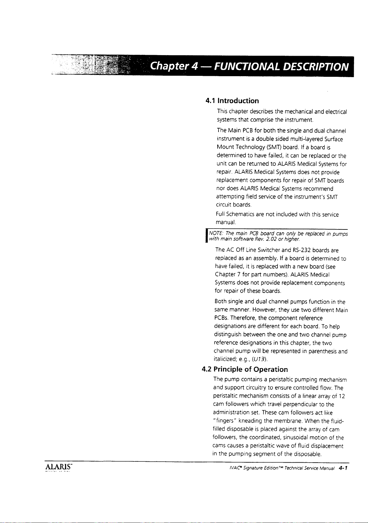
Chapter
4
—
4.1
o
FUNCTIONAL
DESCRIPTION
Introduction
This
chapter
systems
The
Main
instrument
Mount
determined
unit
can
repair.
replacement
nor
does
attempting
circuit
Full
Schematics
manual.
The
with
main
describes
that
comprise
PCB
for
is a double
Technology
to
have
be
returned
ALARIS
boards.
main
software
Medical
components
ALARIS
fieid
are
PCB
Rev,
the
the
both
(SMT)
failed,
to
Medical
service
not
board
2.02
mechanical
instrument.
the
single
sided
board.
it
ALARIS
Systems
for
Systerns
of
the
included
can
only
or
higher.
and
and
dual
multi-layered
If a board
can
be
replaced
Medical
does
repair
instrument’s
with
be
Systems
not
provide
of
SMT
recommend
this
service
replaced
electrical
channel
Surface
is
or
the
for
boards
SMT
in
pumps
ALARIS
The
AC
replaced
have
Chapter 7 for
Systems
for
repair
Both
same
PCBs.
designations
distinguish
reference
channel
italicized;
4.2
Principle
The
pump
and
support
peristaltic
cam
followers
administration
“fingers”
filled
disposable
followers,
cams
in
the
Off
Line
Switcher
as
an
assembly.
failed,
it
is
replaced
part
numbers).
does
not
provide
of
these
boards.
single
and
dual
channel
manner.
Therefore,
Causes a peristaltic
pumping
IVAC
However,
the
are
different
between
designations
pump
will
e.g.,
(U73).
of
Operation
contains a peristaltic
circuitry
mechanism
which
set.
kneading
is
the
coordinated,
segment
Signature
they
component
the
one
in
be
represented
to
ensure
consists
travel
These
cam
the
membrane.
placed
wave
of
Edition™
and
RS-232
If a board
with a new
replacement
is
ALARIS
pumps
use
two
reference
for
each
board.
and
two
this
chapter,
in
pumping
controlled
of a linear
perpendicular
followers
When
against
the
array
sinusoidal
of
fluid
the
disposable.
Technical
Service
boards
are
determined
board
(see
Medical
components
function
different
channel
the
parenthesis
motion
displacement
in
To
help
pump
two
mechanism
flow.
The
array
of
to
the
act
like
the
fluid-
of
cam
of
Manual
the
Main
the
to
and
12
4-1
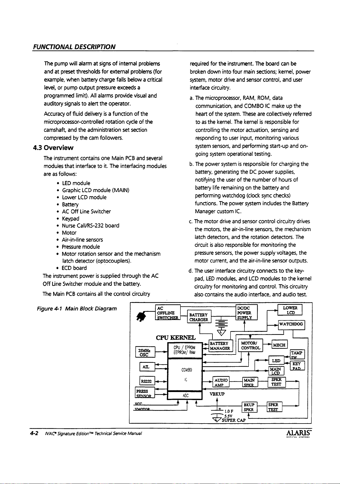
FUNCTIONAL
DESCRIPTION
The
pump
will
alarm
and
at
preset
thresholds
example,
level,
programmed
auditory
Accuracy
when
or
pump
signals
of
battery
output
limit).
to
fluid
microprocessor-controlled
4.3
Figure
4-2
camshaft,
compressed
Overview
The
modules
are
The
Off
The
NAC
and
by
instrument
that
interface
as
follows:
+
LED
module
+
Graphic
e
Lower
»
Battery
e
AC
Off
e
Keypad
e
Nurse
+
+
+
+
e
Call/RS-232
Motor
Air-in-line
Pressure
Motor
latch
detector
ECD
board
instrument
Line
Switcher
Main
PCB
contains
Main
4-1
Signature
Edition™
the
the
contains
LCD
LCD
Line
module
rotation
power
Block
at
signs
of
internal
for
externa!
charge
pressure
All
alarms
alert
delivery
falls
exceeds
provide
the
operator.
is a function
rotation
administration
cam
followers.
one
Main
to
it.
The
module
(MAIN)
module
Switcher
board
sensors
sensor
and
(optocouplers).
is
supplied
module
and
all
the
Diagram
Technical
Service
the
control
problems
problems
(for
below a critical
a
visual
and
of
the
cycle
of
the
set
section
PCB
and
several
interfacing
the
through
modules
mechanism
the
AC
battery.
circuitry
OSC
S
co
-УМОТОВ—
Manual
AC
OFFLINE
SWITCHER
KERNEL
CPU
を
a
>
|
|
CHARGER
EPROM
/
CPU
EEPROM/
COMSO
€
ADO
A
4 4
|
required
broken
system,
interface
a.
for
the
down
motor
circuitry.
The
microprocessor,
communication,
heart
of
the
to as
the
kernel.
controlling
responding
system
sensors,
going
system
b.
The
power
battery,
notifying
battery
generating
el
the
life
performing
functions.
Manager
c.
The
the
latch
circuit
pressure
motor
d.
The
pad,
circuitry
also
BATTERY
|
RAM
The
custom
motor
motors,
detectors,
is
also
sensors,
current,
user
interface
LED
modules,
for
contains
一
一
Ý
ンマ
1
BATTERY
JMANAGER
[K
AUDIO
»|
AMP
VBKUP
4
Lt.
instrument.
into
four
main
drive
and
sensor
RAM,
and
COMBO
system.
the
to
system
These
The
kernel
motor
actuation,
user
input,
and
performing
operational
is
responsible
the
user
of
the
remaining
watchdog
power
on the
(clock
system
IC.
」
drive
and
sensor
ne
the
se
air-in-line
and
the
responsible
the
power
and
the
circuitry
and
monitoring
the
audio
DC/DC
POWER
SUPPLY
I
|
||
|
F
CAP
a
MOTOR/
CONTROL
7
[MAN
BKUP
SPKR
4
一
一
1.0
5.5V
SUPER
The
board
can
sections;
kernel,
control,
ROM,
data
IC
make
are
collectively
is
responsible
sensing
monitoring
start-up
testing.
for
charging
DC
power
supplies,
number
sensors,
rotation
for
air-in-line
LCD
and
interface,
of
hours
battery
sync
control
and
checks)
includes
o
circuitry
the
detectors.
monitoring
supply
voltages,
sensor
connects
modules
control.
to
This
and
4
|
SPKR
TEST
be
power
and
user
up
the
referred
for
and
various
and
of
the
Battery
drives
ve
mechanism
The
the
the
outputs.
the
key-
to
the
kernel
circuitry
audio
test.
LOWER
LCD
=
全 人 AvATE
on-
the
.
|
NN

Table
4-1.
80C188
A/D
(A2D)
Battery
Sensor
Battery
Channel
Channel
COMBO
DIP
EEPROM
EMI
EMC
EPROM
ESD
Kernel
Keypad
LCD
Module
LED
Module
Mechanism
Latch
Detector
Motor
Rotation
PLCC
Battery
Manager
PQFP
RAM
System
UART
Ultrasonic
Transducer
VCO
Watchdog
Definition
Temperature
Assembly
A
B
IC
Detector
AIL
of
Terms
Microprocessor
Analog
Monitors
Contains
Refers
Refers
A
Dual
through
Electrically
under
Electromagnetic
Electromagnetic
other
Erasable
change.
to
to
to
custom
Inline
a
CPU
electrical
Programmable
Data
digital
the
battery,
left
the
integrated
Package.
printed
Erasable
control.
Electrostatic
Circuit
and
Membrane
Liquid
information.
A
status
Optical
Optical
Plastic
of a printed
Custom
LCD
Plastic
Random
power
A
Universal
stream
A
Voltage
control
consisting
time
crystal
custom
indicators,
switch
switch
Leaded
Display,
Quad
is
circuit
for
sensor
controlled
voltage.
bases.
switch
light
circuit
programmed
Access
removed.
which
Asynchronous
remote
used
that
controls
converter.
temperature
battery
mechanism,
right
circuit
temperature
mechanism,
circuit
A
form
board.
Programmable
Data
is
interference.
Compatibility.
devices.
Read
is
not
lost
if
power
Discharge.
of
CPU,
program
panel.
display
power
Flat
(LCD)
emitting
to
used
Chip
Memory.
monitors
diode
and
a
custom
detect
the
with a decoder
Carrier.
board.
microcontroller,
on
and
Package. A surface
Memory
the
Receiver
communications.
to
detect
air
in
oscillator.
all
instrument
inside
battery
sensors,
and
sensors,
with
many
of
electronic
Read
not
lost
if
The
ability
Only
Memory.
is
removed.
memory
for
alpha-numeric
(LED)
module
integrated
status
of
disk.
A
form
of
watchdog
mountable
whose
proper
operation
Transmitter.
the
tubing.
An
oscillator
operations.
to
ensure
sensor,
power
the
electronic
used
functions.
LED
module.
and
LED
O
functions.
part
Only
Memory.
is
of
the
Memory
(EPROM),
display
that
circuit.
latch
on
for
data
can
of
and
packaging
removed.
battery
A
Passes
where
optimum
thermal
module.
Memory
instrument
whose
data
(128
contains
the
mechanism.
part
packaging
management,
electronic
change
the
80C
188
logic
device
high
frequency
output
frequency
FUNCTIONAL
battery
cutout.
which
mounts
whose
to
operate
data
is
fixed
memory
x
64)
numeric
package.
under
which
(RAM),
of
prompts,
LED's,
which
CPU
microprocessor
formats
sound
can
DESCRIPTION
capacity.
on
pins
data
can
in
the
and
associated
status,
annunciator
mounts
control
of
control.
and
data
through
be
varied
extending
change
presence
does
not
and
blocks,
on
the
surface
the
Lower
Data
is
lost
clocks.
as
a
serial
fluid
filled
through
of
I/O,
setup
if
bit
set.
a
MEGICAL
SYSTEMS
S
IVAC
Signature
Edition'M Technical
Service
Manual
4-3

FUNCTIONAL
4.4
Main
4.4.1
4.4.2
Processor
The
processor
the
motor
input,
monitoring
performing
operational
80C188
EPROM
backed
has
2K
bits
serial
communications
The
COMBO
(Application
incorporates
and
other
has a 16
periodically
also
contains
used
to
as
the
A/D,
Manager.
Section
The
RS-232
baud.
COMBO
an
communications
protected
4.4.2
kernel
level
The
industry
232/Nurse
The
interface
along
with
COMBO
The
COMBO
which
supports a variety
audio
support,
COMBO
latched
COMBO
to
addresses
periodically
DESCRIPTION
PCB
Kernel
kernel
is
actuation,
start-up
testing.
microprocessor
program
up
RAM
of
IC
Specific
timing,
system
bit
CRC
test
the
interface
EEPROM,
Additional
“COMBO
data
serial
UART
IC,
while
standard
to
10
Call
supports
ground.
IC,
latches
IC
has a 16
test
sensing
various
and
The
storage,
data
storage.
EEPROM
interface.
U10
(U74)
Integrated
address
“giue”
generator
the
EPROM
local
serial
to
serially
LED
information
communications
communications
function
the
RS-232
RS-232
channel
kV
with
board
and
two
IC
U10
(U74),
digital
/O
the
address
as
A19-A16,
bit
CRC
the
EPROM
responsible
system
on-going
kernel
U11
and
memory
for
and
responding
sensors,
system
is
based
(U15),
512K
64K
Bytes
In
addition,
and a 9600
is a custom
Circuit)
decoding,
functions.
which
data.
The
is
The
interface
accessed
Module(s),
can
IC".
function
up
is
embedded
interface
level
converter
is
EMI
filtered
components
is
not
electrically
signals
(TxD
is a 160
of
kernel
and
bus
generator
functions,
other
and
and
A7-A0.
data.
pin
functions.
The
controlling
to
and
on a 16
Bytes
of
battery
the
kernel
baud
ASIC
which
digital
1/0,
Combo
used
to
COMBO
control
peripherals
and
be
to
in
is
and
on
logic
Battery
found
supports
9600
the
based
chip.
ESD
the
RS-
IC
in
isolated.
and
RxD)
PQFP
device
primary
The
outputs
The
which
RAMTEST
the
is
user
bit
of
IC
such
on
The
used
circuit
detection
control
peripherals
Module(s),
generates
The
UART
counters
inside
for
motor
are
also
4.4.3
The
EEPROM
EEPROM
diagnostic
accessed
COMBO
device
COMBO
This
device
store
to
the
configuration
settings,
instrument
battery
İvore:
4.4.4
The
Volume
PRI/SEC,
provides
redundant
The
RAM
RAM
written
main
The
processor
RAM.
COMBO
the
two
match, a bit
COMBO
When
provides
of
RAM
logic
is
such
and
the
Main
(intel
(Intel
the
COMBO
control
within
is
settings.
using
IC.
Data
through
chip.
holds
data
that
instrument.
mode,
and
certain
ID
number,
run
time,
event
log
is
used
To Be
Infused
as
well
read/write
storage
to
RAM
RAM,
U8
reads
The
phantom
IC.
The
RAMs
on
will
IC.
the
pump
redundant
data.
used
to
as
the
Battery
LCD
8251
equivalent)
8254
equivalent)
chip.
and
LCD
the
custom
used
to
The
the
serial
is
written and
the
seria!
128,
sixteen
will
not
The
EEPROM
calibration
diagnostic
and
total
is
not
stored
to
store
(VTBI),
as
the
event
memory
and
is
stored
(U9)
and
data
RAM
COMBO
each
be
set
in a register
is
off
the
storage
The
local
interface
A/D
converter,
Manager.
interface
Six
pulse
backlight
IC.
store
all
configuration
EEPROM,
control
read
data
registers
bit
be
destroyed
will
(LCD
information
PM
interval,
instrument
in
the
user
set
mode,
log.
integrity
automatic
in
both
phantom
directly
data
only
IC
compares
read.
If
the
VRAM
and
error
serial
interface
with
serial
EEPROM,
The
device
control
and
are
width
U9
unit
words.
signals.
three
also
provided
modulators
and
contrast
(U11)
within
back
within
It
if
power
store
contrast)
PM
on/off,
run
EEPROM.
parameters,
rate,
and
The
instrument
by
using
comparison.
of
the
RAM
RAM,
U4
from
the
goes
to
the
data
does
within
the
supply
is
accessed
also
16
bit
and
is
the
from
the
the
is
used
is
lost
e.g.,
time.
e.g.,
Data
devices,
(U5).
main
the
data
from
not
still
on,
LED
to
4-4
IVAC@
Signature
Edition™
Technical
Service
Manual
MEDICAL
SYSTEMS

FUNCTIONAL
DESCRIPTION
preserving
chip
RST_CPU*,
during
4.4.5
The
(x8)
socket.
be
from
the
4.4.6
The
UART
which
equivalent
ive
drive
Figure
4-2-a
the
select
power
EPROM
EPROM
of
program
To
change
opened.
AC
power
EPROM
RS-232
RS-232
serial
(Universal
is
located
to
¡
interface
COMBO
contents
line,
CS2,
so
that
down
(CMOS),
memory.
Turn
before
Interface
of
of
the
the
RAMs
sequence.
U3
the
EPROM
the
instrument
opening
(7100/7200
communications
Asynchronous
inside
the
an
Intel
8251.
U22
(U45),
IC
Block
the
RAMs.
The
RAMs
is
tied
to
can
not
be
selected
(U4),
contains
The
EPROM
the
the
Receiver/Transmitter)
COMBO
The
i ;
which
Diagram
512K
is
held
instrument
off
and
disconnect
case
to
only)
is
supported
IC.
The
UART's
converts
outputs
second
bytes
in
a
must
replace
by
UART
the
logic
a
is
level
up
4.4.7
The
electrical
RS-232
well
and
created
signals
isolated
generated
to
Limit
nominally
required
NOTE:
[wore
signals
to
9600
RS-232
isolated
isolation
connector
as
connections
flow
sensor
using
and
circuit
by
generate
resistor
+6V,
by
The
RS-232
and
hence
to
RS232
levels.
baud
rate.
Interface
RS-232
an
the
R1
U1.
Interface
between
and
the
for
the
interface
optical
isolators
isolation
power.
the
appropriate
power
Voltage
MAX250/25 1 chip
converts
to
match
board
cannot
in
have
The
system
(7101/7201
provides
the
rest
of
speaker,
option.
U3
RS-232
the
instrument
tamper
The
isolation
and
U4
only)
transformer
level
conversions
set
signal
conditioning.
the
RS-232
the
input
the
International
trhe
Nurse
signal
signal
Call
can
support
SOOVAC
signals
switch,
for
the
T1
U1
and
levels,
range
version
option.
on
as
is
for
are
U2
the
is
Figure
MEDICAL
4-2-b
SYSTEMS
COMBO
IC
Block
Diagram
«a
ET
B
Tad
nonisolated
interface
MM
IVAC
Signature
nome
Optical
later
TT]
pat
|
Edition™
Technical
ye)
(interface | o,
Service
了 J eşe
Manual
4-5
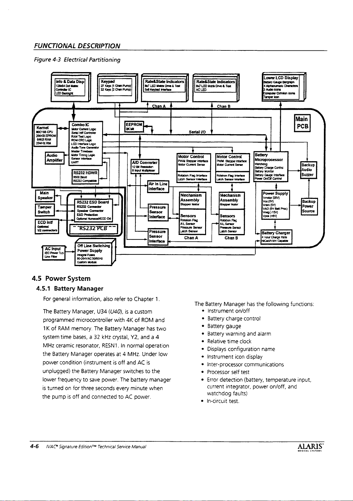
FUNCTIONAL
DESCRIPTION
Figure
Kernet
800188
256KB
EPROM
S4KB
RAM
25MHz
Xtal
Ampliter
speaker
Tamper
Switch
ECD
Optional
AC
(EC
Line
4-3
Info & Data Disp
12x64
Controller
LED
Backlight
ani
CPU
.
Audio
i
η
|
Int!
Input
Pou
Fior
Electrical
Dot
Matrix
IC
Partitioning
Combo
IC
Motor
Current
Logic
Serie)
if
Controller
RAM
Test
Logic
ROM
CRC
Logic
LCD
Interface
Logic
Audio
Tone
Timebese
Master
fe]
Wow
mn
VART
RS232
HDWR
Roa?
Compete
|
RS232
ESD
RS232
Connector
‘Speaker
ESD
Protection
Optional
一
Off
[o]
Line
Power
Supply
90-264VAC
Custom
Module
Keypad
27
Keys
32
Keys
n
“
|
Board | |
Con
ЕСО
СМ
一 一 |
一
Switching
SO/50HZ
(1
Chen
Pump)
(2
Chan
Pump);
EEPROM
2K
Rate&
8x7
LED
58
Keyped
bit e y
1
|
AID
Converter
;
12
Bt
Resolution
8
Input
Mutipler
Air
Interface
L$
Pressure
Sensor
Interface
Sensor
Interface
u
|
「
Motor
weer
Rowton
Latch
Mechanism
A
AC
.
Serial
Y
Control
Currert
Png
Sensor
State
Indicators | Rate&State
Matrx
Orve & Test BJ
interface
=
in
Line
Assembly
Sensors
Rotation
Flag
AIL
Sensor
Pressure
Sensor
Chan
A
Indicators
LED
Matrix
Drive & Test
LED
À
Chan
B
—
|
VO
』
Motor
Sense
intertace
Mowe
Current
Latch
Sensor
q 1
Mechanism
[Assembly
ー
Sensors
Rotation
Г
AL
Sensor
[Pressure
Chan
1
+
Controt
Sense
Fc
interface
4
Flag
Sensor
B
20009
|
oo
1
Y
00000
Main
PCB
|
N
Backu
p
Audio
Buzzer
Backup
power
ource
4.5
4-6
4.5.1
The
system
MHz
the
power
unplugged)
lower
is
the
Power
System
Battery
For
general
Battery
programmed
1K
of
RAM
time
ceramic
Battery
Manager
condition
frequency
turned
on
pump
is
IVAC*
Signature
Manager
information,
Manager,
U34
also
(U40),
microcontroller
memory.
bases, a 32
resonator,
The
Battery
kHz
RESN1.
operates
(instrument
the
Battery
for
three
off
and
Edition™
to
save
seconds
connected
Manager
power.
Technical
refer
to
Chapter
is a custom
with
4K
of
ROM
Manager
crystal,
Y2,
and a 4
In
normal
at 4 MHz. Under
is
off
and
AC
switches
The
battery
every
minute
to
AC
power.
Service
Manual
1.
and
has
two
operation
low
is
to
the
manager
when
The
Battery
Instrument
Battery
Battery
Battery
Relative
Displays
Instrument
Inter-processor
Processor
Error
current
watchdog
In-circuit
Manager
charge
gauge
warning
time
has
on/off
contro!
and
clock
configuration
icon
display
communications
self
test
detection
(battery,
integrator,
faults)
test.
the
following
alarm
name
temperature
power
on/off,
and
functions:
input,
MEDICAL
SYSTEMS
S
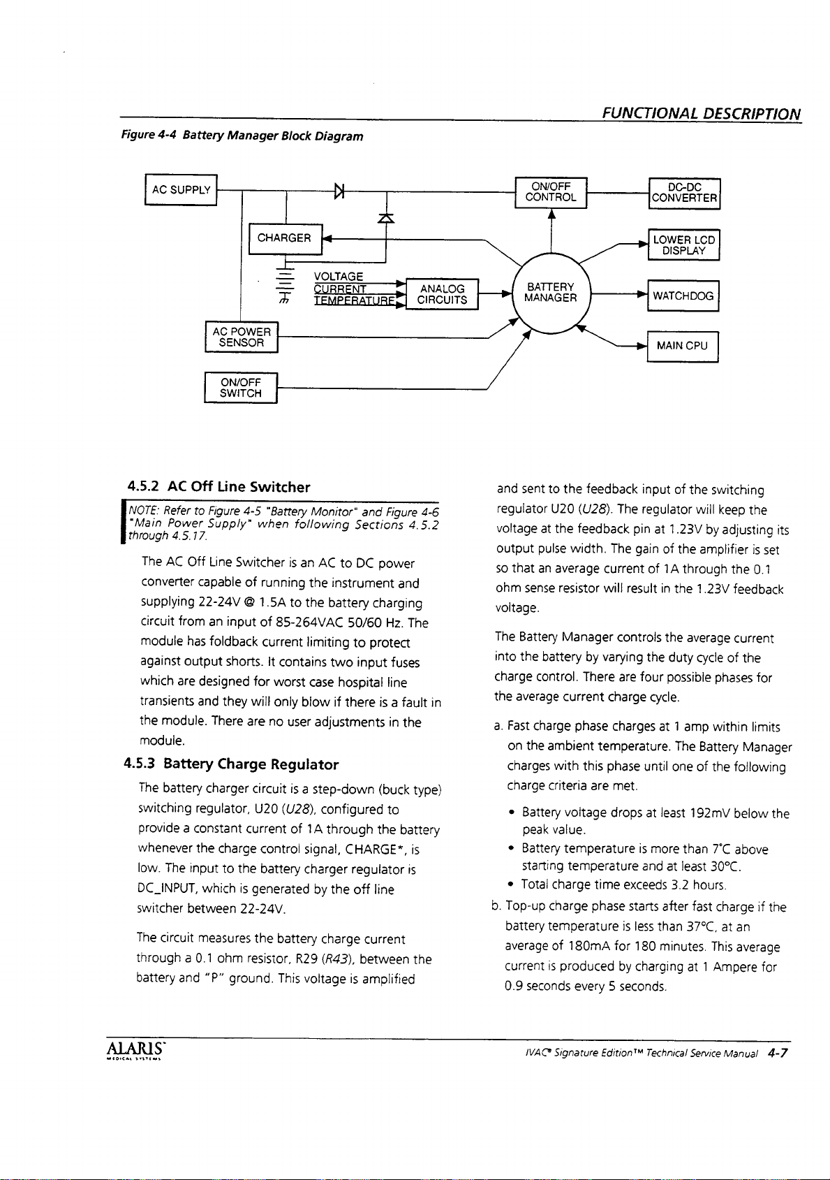
Figure
4-4
Battery
Manager
Block
Diagram
FUNCTIONAL
DESCRIPTION
AC
SUPPLY
4.5.2
AC
[<
Refer
“Main
Power
through
The
AC
converter
supplying
circuit
4.5.17.
module
against
which
transients
module.
the
module.
4.5.3
Battery
The
battery
switching
provide
whenever
The
low.
DC_INPUT,
switcher
The
circuit
through a 0.1
battery
AC
Off
to
Figure
Supply”
Off Line
capable
22-24V
an
from
foldback
has
output
designed
are
and
There
charger
regulator,
a
constant
the
input
which
between
measures
and
“P”
CHARGER
POWER
SENSOR
ON/OFF
SWITCH
Line
Switcher
4-5
when
Switcher
of
@
input
shorts.
for
will
they
are
Charge
circuit
U20
current
charge
the
to
is
generated
22-24V.
the
ohm
resistor,
ground.
—
=
一
一
+
“Battery
following
is
an
running
to
1.5A
85-264VAC
of
current
It
contains
worst
blow
only
user
no
Regulator
is
a
(U28),
of
control
battery
battery
R29
This
voltage
NL_
A
VOLTAGE
ТТ
CURRE
TEMPERATURE? | CIRCUITS
Monitor"
AC
instrument
the
battery
the
limiting
two
case
if
adjustments
step-down
configured
through
1A
signal,
charger
the
by
charge
(R43),
I
Ч
and
Sections
to
DC
power
charging
50/60
protect
to
input
hospital
is
there
(buck
the
CHARGE”,
regulator
line
off
current
between
is
amplified
|
>
Figure
4.5.2
and
The
Hz.
fuses
line
a
fault
in
the
to
battery
is
is
ANA
4-6
in
type)
the
ON/OFF
CONTROL
BATTERY
MANAGER
and
sent
regulator
voltage
output
so
that
ohm
sense
voltage.
The
Battery
into
the
charge
the
a.
b.
control.
average
Fast
charge
on
the
charges
charge
»
Battery
peak
e
Battery
starting
e
Total
Top-up
battery
average
current
0.9
seconds
to
the
feedback
U20
(U28).
at
the
feedback
pulse
width.
an
average
resistor
Manager
battery
by
There
current
phase
ambient
with
this
criteria
charge
temperature
is
are
voltage
value.
temperature
temperature
charge
time
phase
of
180mA
produced
every 5 seconds.
CONVERTER
|
LOWER
DISPLAY
WATCHDOG
MAIN
input
The
regulator
pin
at
The
gain
of
current
will
varying
temperature.
result
controls
are
four
charge
charges
phase
until
met.
drops
is
and
exceeds
starts
is
less
for
180
by
charging
of
1A
in
the
the
possible
cycle.
at 1 amp
at
least
more
at
after
than
minutes.
DC-DC
LCD
CPU
of
the
will
1.23V
by
the
amplifier
through
the
1.23V
average
duty
cycle
The
Battery
one
of
192mV
than
least
3.2
hours.
fast
37°C,
at 1 Ampere
switching
keep
the
adjusting
is
set
the
0.1
feedback
current
of
the
phases
for
within
limits
Manager
the
following
below
7°C
above
30°C.
charge
if
at
an
This
average
for
its
the
the
ALARIS
MEDICAL
αν
IVAC
Signature
Edition™
Technical
Service
Manual
4-7
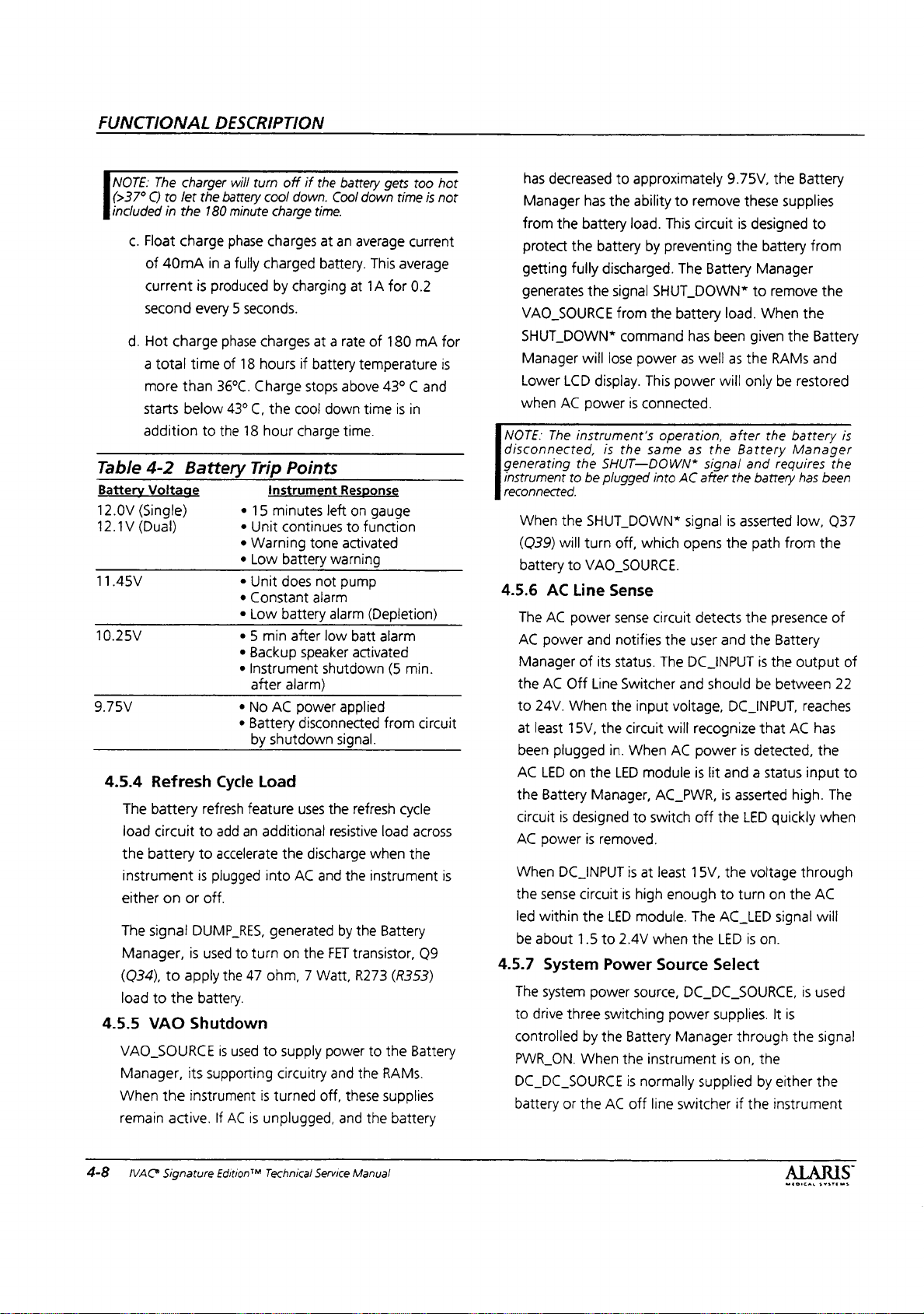
FUNCTIONAL
DESCRIPTION
NOTE:
(>37°
included
c.
d.
Table
Battery
12.0V
12.1V
11.45V
10.25V
9.75V
4.5.4
The
load
the
instrument
either
The
Manager,
(Q34),
load
4.5.5
VAO_SOURCE
Manager,
When
remain
The
charger
C)
to
let
in
the
Float
charge
of
40mA
current
second
Hot
a
more
starts
addition
4-2
every 5 seconds.
charge
total
time
than
below
Battery
Voltage
(Single)
(Dual)
Refresh
battery
circuit
battery
on
or
signal
DUMP_RES,
is
to
apply
to
the
VAO
Shutdown
its
the
instrument
active.
will
the
battery
180
minute
phase
in a fully
is
produced
phase
of
18
36°C.
43°
C,
to
the
18
Trip
e
e
Unit
*
Warning
*
Low
e
Unit
e
Constant
*
Low
e 5 min
*
Backup
e
Instrument
after
e
No
*
Battery
by
Cycle
refresh
feature
to
add
an
to
accelerate
is
plugged
off.
used
to
turn
the
47
battery.
is
used
supporting
If
AC
is
turn
off
if
cool
down.
charge
time.
charges
charged
by
charging
charges
hours
Charge
hour
the
at a rate
if
battery
stops
cool
charge
Points
instrument
15
minutes
continues
tone
battery
does
not
alarm
battery
after
speaker
alarm)
AC
power
disconnected
shutdown
Load
uses
additional
the
discharge
into
AC
generated
on
the
ohm, 7 Watt,
to
supply
circuitry
is
turned
unplugged,
the
battery
Cool
down
at
an
average
battery.
at
This
1A
of
temperature
above
down
time
time.
Response
left
on
gauge
to
function
activated
warning
pump
alarm
(Depietion)
low
batt
activated
shutdown
applied
signal.
the
refresh
resistive
when
and
the
instrument
by
the
FET
transistor,
R273
power
to
and
the
off,
these
and
the
gets
too
time
is
current
average
for
0.2
180
mA
43° C and
is
in
alarm
(5
min.
from
circuit
cycle
load
across
the
Battery
Q9
(R353)
the
Battery
RAMs.
supplies
battery
hot
not
for
is
is
has
decreased
Manager
from
the
protect
getting
generates
VAO
SOURCE
SHUT
DOWN*
Manager
Lower
when
AC
NOTE:
The
disconnected,
generating
instrument
reconnected.
When
the
(Q39)
will
battery
4.5.6
AC
The
AC
AC
power
Manager
the
AC
to
24V.
at
least
been
plugged
AC
LED
the
Battery
circuit
is
AC
power
When
DC
the
sense
led
within
be
about
4.5.7
System
The
system
to
drive
controlled
PWR_ON.
DC_DC_SOURCE
battery
to
has
the
battery
the
battery
fully
discharged.
the
signal
from
command
will
lose
LCD
display.
power
is
instrument's
is
the
the
SHUT—DOWN*
to
be
plugged
SHUT_DOWN*
turn
off,
to
VAO_SOURCE.
Line
Sense
power
sense
and
notifies
of
its
status.
Off
Line
Switcher
When
the
15V,
the
circuit
in.
When
on
the
LED
Manager,
designed
is
removed.
INPUT
circuit
1.5
the
LED
to
is
is
2.4V
Power
power
three
switching
by
the
Battery
When
the
is
or
the
AC
off
approximately
ability
to
remove
load.
This
circuit
by
preventing
The
Battery
SHUT
DOWN*
the
battery
has
power
as
weil
This
power
connected.
operation,
same
as
the
AC
signal
opens
the
user
The
DC_INPUT
and
voltage,
will
recognize
AC
power
is
off
least
15V,
enough
The
the
signal
after
detects
should
lit
into
which
circuit
input
module
AC_PWR,
to
switch
at
high
module.
when
Source
source,
DC_DC_SOURCE,
power
Manager
instrument
normally
line
switcher
supplied
9.75V,
the
these
is
designed
the
battery
Manager
to
remove
load.
When
been
given
as
the
RAMs
will
only
be
after
the
Battery
and
requires
the
battery
is
asserted
the
path
the
presence
and
the
Battery
is
the
be
between
DC
INPUT,
that
is
detected,
and a status
is
asserted
the
LED
quickly
the
voltage
to
turn
on
AC_LED
LED
is
signal
on.
Select
supplies.
ts
It
through
on,
the
by
if
the
instrument
either
Battery
supplies
to
from
the
the
the
Battery
and
restored
battery
Manager
the
has
been
low,
Q37
from
the
of
output
reaches
AC
has
the
input
high.
The
when
through
the
AC
will
is
used
is
the
signal
the
is
of
22
to
4-8
IVAC
Signature
Edition™
Technical
Service
Manual
ALARIS
MEDICAL
SYSTEMS
is
plugged
the
AC
When
Q24
will
turn
by
the
If
PWR_AC
DC_DC_SOURCE
4.5.8
The
Battery
through
range
voltage
reguirements.
subtracter-multiplier
scale
+15
The
Battery
charging,
alarm
When
remove
MEASURE
VMEAS
4.5.9
VMEAS
VMEAS
reference
current
VMEAS
the
instrument
the
load
Manager
the
battery's
The
12V
gate
and
gate
to
but
the
only
rated
into
source
the
Battery
(Q41)
will
on,
DC_INPUT.
is
Battery
battery
counts
Manager
its
internal
of
the
must
the
battery
(1
Manager
battery
and
warning
MEASURE
BATT_PLUS
being
is
removed
is
the
voltage
circuit,
monitor
off
by
on
the
turns
Zener
source
source
Vgs
(Voltage
to
during
turn
and
high,
Voltage
A/D
be
The
count = 1mV).
supply
setting
is
battery.
VMEAS
voltage
CR31
voltage.
20V.
AC.
The
Battery
the
Manager
on. f PWR_AC
DC_DC_SOURCE
Q8
(027)
will
be
supplied
Monitor
can
range
monitors
A/D
converter.
converter
reduced
voltage and
gauge,
to
4.1V
reference
amplifier
uses
error
the
features.
is
low
Q27
from
input
low
will
open
as
well.
used
to
the
voltage
circuit.
The
the
MEASURE
off
and
AC
In
this
on
once a minute
and
temperature.
(CR47)
of
the
FET,
The
gate
to
Manager
battery
asserts
is
on
from
the
battery
is 0 to
meet
circuit
maintain
battery
detection,
(Q43)
to
Q26
power
monitor
Battery
is
unplugged
condition,
is
placed
Q26
(Q45),
FET can
source)
refresh
PWR_ON
is
high,
will
be
and
by
the
10
to
voltage
The
valid
4.1V.
The
the
input
and
the
U29-5
an
voltage
will
open
U29
(U37).
(Q45)
the
REF
circuit,
Manager
signal
between
to
see
up
of
the
disconnects
cycle.
high,
07
(225)
supplied
battery.
18V.
The
input
battery
voltage
(U37-5)
accuracy
and
so
low
to
the
to
limit
to
FET
for
battery
and
Also
that
4.1V
and
the
turns
when
reduce
Battery
check
the
the
24V
is
of
its
4.5.10
Voltage
The
4.1V
circuit,
ambient
reference
the
Manager.
VMEAS,
the
precision
4.5.11
The
ohm
The
System
circuit
resistor,
resistor
ground
ground,
(The
battery
that
the
system
designed
voltage
current
operational
voltage
current
thereby
load
will
will
leveis
charges
feedback
The
Battery
ms, 1 ms
the
signal
high
will
across
the
resulting
input
of
the
output
Manager
signal
is
pulsed
between
measurement.
measured
out
of
battery,
present
functions.
power
FUNCTIONAL
Reference
reference
battery
temperature
voltage
The
which
to
from
the
battery
as
be
amp's
integrating
transistor,
Manager
before
RESET I high
turn
feedback
output
the
voltage
samples | MON
the
for:
temperature
for
reference
can
be
reference
Current
measure
R32
(R86),
is
placed
the
AC
ground
charger
charge
current).
an
integrator.
be
less
than
generated
negative
at
the
the
feedback
the
resetting
on
Q30
voltage, | MON,
Battery
Manager.
is
high
two
samples
The
Battery
charging,
battery
requirements,
4.1V
is
used
in
the
sensor
circuit,
the
A/D
converter
voltage
between
Zener
U27
Monitor
the
supply
to
generate a voltage
between
Off
to
the
circuit
The
operational
Q30
integrates
for 1 ms.
(Q48)
capacitor,
about
and
gauge,
“P”
Line
Switcher,
rest
is
tied
current
amplifier,
Since
the
“L”
in a resistor
input,
capacitor,
current
(Q48)
the
thereby
2.7V.
once
once
becomes
Manager
to
monitor
and
updates
as
is
integrator
C52
At a 1A
before
after.
DESCRIPTION
voltage
sensor
circuit,
and
is
in
is
4.096V
7.7
to
24V,
(U47).
current
ground,
and
of
the
instrument
to
“P”
ground
is
not
measured
U29-7,
the
“P”
ground
ground
amp
the
Forcing
voltage
tied
to
maintain
inputs.
C52
long
as
off.
current
by
RESET
placing a short
(C56).
is
fed
to
load
The
Battery
the
The
difference
the
current
uses
the
current
gauge
error
detection
monitor
the
the
the
Battery
+2%.
turns
on
uses a 0.1
drop.
the
“L”
so
as
(U37-7)
a
to
the
equal
This
(C56),
the
for
100
pulsing
|
The
an
A/D
current
RESET
|
current
in
and
under
is
IVAC®
Signature
Edition™
Technical
Service
Manual
4-9
FUNCTIONAL
DESCRIPTION
4.5.12
4.5.13
Always
The
always
devices
off
e.g.,
supply
is
System
The
system
+5V,
+29V,
motor,
and
an
integrated
thermal
internal
The
DC_DC_SOURCE
switching
a.
The
+5V
(“buck”)
provides a lower
input
excess
limit
circuit
failure.
which
until
the
sense
reference
inductive
catch
b.
The
VMOTOR
(“boost”)
voltage
24V).
has a soft
starting.
output
releases
of a diode.
and
the
reference
c.
The
VNEG
which
On
Supply
on
supply,
that
remain
Battery
regulated
U39
powered
Manager
at
5V
(U43),
circuitry
+5%.
Switching
switching
and
sensor
switching
overload
reference,
power
supply
configuration
voltage
of
1A
damage
The
regulator
turns
output
resistors,
voltage.
flyback
diode.
supply
(29V
The
supply
start
The
side
of
it,
generating
This
loop
signal
supply
generates a negative
supplies
-15V
power
circuits.
regulator
protection,
and current
voltage
supplies:
U17
(U31)
output
(10V-24V).
peak.
Output
in
has
on
current
voltage,
reaches
It
then
voltage
supply
U21
which
+1.5V)
than
can
provide
feature
internal
the
pass
power
about
voltage
controlled
level.
U16
(U30)
Each
switching
voltage
The
the
an
to
as
the
turns
created
provides a higher
the
to
limit
inductor
is
sensed
to
(+5VAO)
is
used
to
when
the
instrument
and
VRAM.
Supplies
provide
to
internal
limit
is
is a step
clamp
event
internal
the
sensed
internal
(U26)
element
29V
generate a 1.23V
is a buck-boost
supply
regulated
the
logic,
of
the
supplies
IC
which
oscillator,
functionality.
applied
to
down
regulator
(SV
+5%)
supply
can
Zener
of
regulation
pass
output
inductor
through
1.23V
off
and
the
is
clamped
is a step
input
supply
up
to
1A
peak
inrush
current
shorts
to
ground,
at
the
by a resistor
(-15V
display,
provides
three
provide
diodes
up
the
cathode
+1V)
power
The
uses
which
than
element
the
by
a
output
(9V-
and
upon
then
pair
supply
is
in
from a positive
provide
bootstrapped
Then,
potential
voltage
internal
inductor
off,
negative
capacitor
4.5.14
The
VRAM
RAMs
turned
sourced
instrument
diode.
4.5.15
4.5.16
VPOS
A
linear
provides a 6V
circuits.
A/D
voltage
times
the
supplied
reference
used
as a pass
supplied
Battery
The
battery
temperature
10
kiliohm @ 25°C
same
type
circuit.
accuracy,
circuit
thermistor
input
voltage.
input
to
The
Battery
its
error
about
to
referencing
allows
and
therefore
pass
element
while
the
flyback
voitage
though a steering
VRAM
Supply
supply
to
keep
them
off.
When
by
+5VAO
is
on,
Supply
regulator,
supply
The
output
gain
of
the
input
reference
by
the
DC_DC_
is
ADVREF_RAW.
transistor
by
the
amplifier.
Temperature
temperature
in
the
as
used
The
sensor
over
the
is a voltage
with a 4.1V
The
the
Battery
Manager
detection
supply
(9V-24V).
100mA.
on.
action
is a 4.8V
the
VRAM
U2
The
IC
the
negative
the
feedback
the
chip
to
sense
regulate
provides
When
the
of
the
spike
which
diode.
supply
active
when
instrument
through a diode.
is
sourced
(U7),
from a DC-DC
for
the
pressure
voltage
amplifier,
approximately
voltage.
SOURCE
The
to
boost
Sensor
sense
circuit
battery
thermistor.
in
will
temperature
divider
pack
The
the
ambient
measure,
range
between a resistor
reference
output
and
BATT_TEMP
Manager.
uses
the
charging
battery
functions.
The
supply
can
ground
output
current
pass
inductor
is
the
is
pin
voltage.
signal
to
the
negative
it.
In
operation,
through
element
generates
captured
generated
instrument
off,
VRAM
When
the
by
+5V
through
is
ground
turns
across
for
is
is
Source
transducer
is
dependent
The
power
while
the
transistor
the
current
measures
through a nominal
thermistor
temperature
with a 2.5°C
0°
to
voltage
used
drives
temperature
1.5
Q1
is
65°C.
and
an
and
on
is
(Q1)is
the
the
sense
The
the
as
the
A/D
the
the
a
a
the
a
the
in
4-10
VAC
Signature
Edition™
Technical
Service
Manual
ALARIS
MEDICAL
SYSTEMS
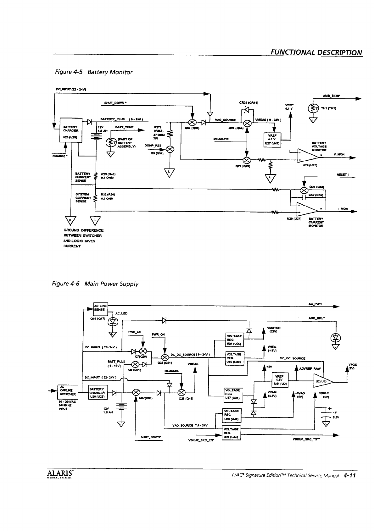
Figure
DC.
INPUT
BATTERY
CHARGER
V20 (U2e)
À
CHARGE
*
GROUNO
BETWEEN
AND
CURRENT
4-5
Battery
(22 - 24V)
BATTERY 2 R29
SENSE
SYSTEM
CURRENT
г
DIFFERENCE
SWITCHER
LOGIC
GIVES
Monitor
SHUT.
BATTERY,
12V
18
AH
=
(R43)
P
0104
R32
(RBS)
0.1
OHM
7
DOWN
*
PLUS
BATT
TEMP
(PART
BATTERY
ASSEMBLY)
(9-19)
OF
R31
(CRA1)
FUNCTIONAL
vrer
。
ww 一 一
aan
DESCRIPTION
AMB
TEMP
TH1
(TH1)
29
(U37)
020
(048)
|
C52(CS6)
|
um
BATTERY
CURRENT
MONITOR
|
LMON
}
DD
Figure
»
om
SWITCHER
85 - 264VAC
60/60
INPUT
4-6
Main
Q15
DC
INPUT
DC
INPUT
BATTERY
CHARGER
HZ
=
AC
SENSE
(047)
Power
LINE
24V
(22-
BATT
ES
180]
(22-24V)
a
18
Supply
AC_LED
}
PLUS
PWR
98
(0721)
AC
N
Wo
PWR_ON
MEASURE
DG
DC
VAO
SOURCE
VMEAS
(045)
26
SOURCE
VEKUP
($-
24V
7.6 - 24V
SRC
)
EN
VOLTAGE
REG
421
VOLTAGE
REG
U16
VOLTAGE
REG
(U31)
U17
VOLTAGE
REG
U39
(U43)
VOLTAGE
REG
UST
(044)
(426)
(U30)
AC
PWR
VMOTOR
(2900)
УМЕС
çiy
DC.
DC.
és
wv
(U2)
SOURCE
RAW
7
154)
osv
tasv)
(ev)
B
+
1F
μα
”
VEKUP_SRC_TST-
—+-
MEDICAL
SYSTEMS
MAC
Signature
Edition™
Technical
Service
Manual
4-11
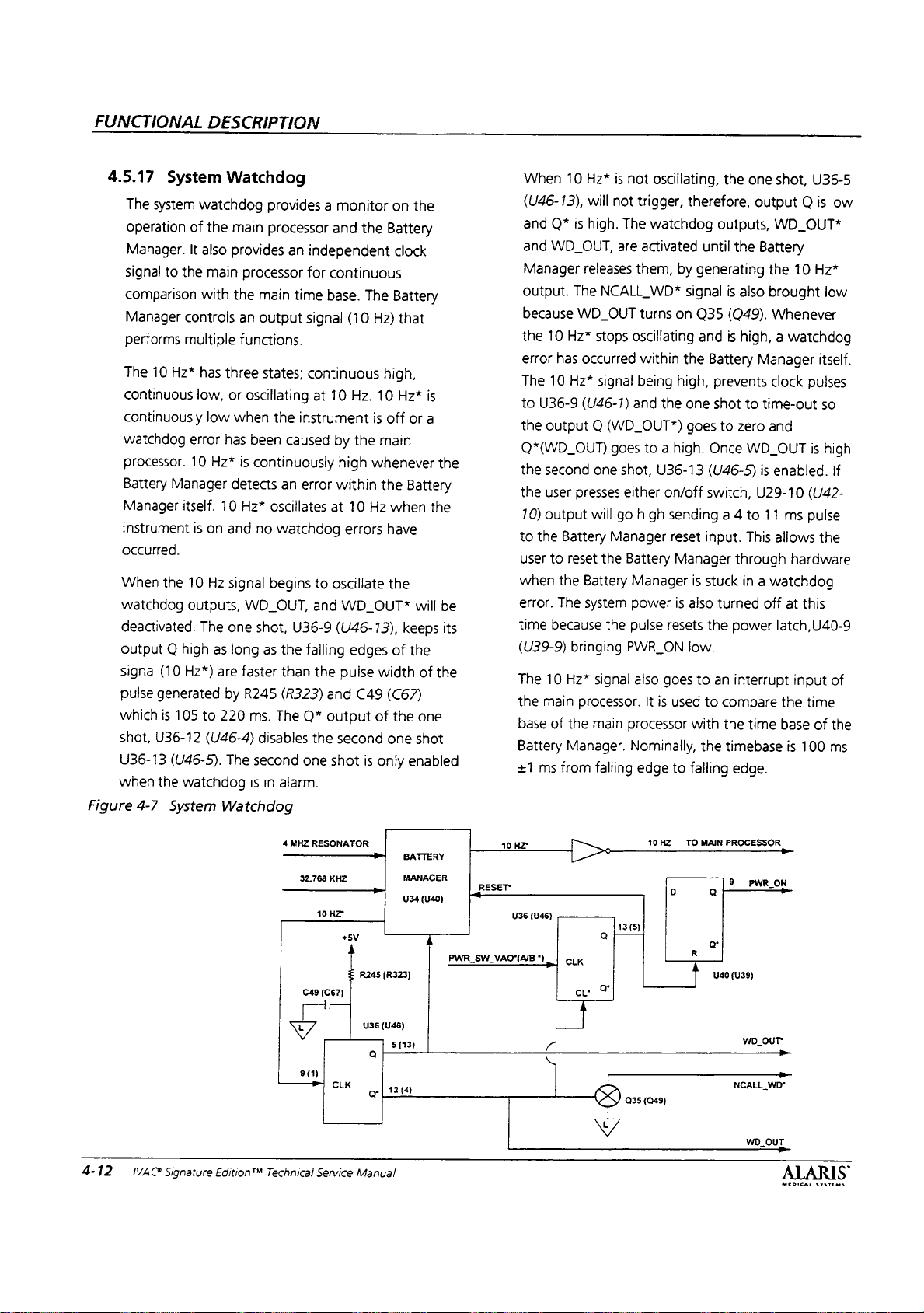
FUNCTIONAL
DESCRIPTION
4.5.17
The
operation
Manager.
signa!
comparison
Manager
performs
The
continuous
continuously
watchdog
processor.
Battery
Manager
instrument
occurred.
When
watchdog
deactivated.
Output Q high
signal
pulse
which
shot,
U36-13
when
Figure
4-7
System
system
watchdog
of
It
also
to
the
with
controls
multiple
10
Hz*
has
low,
error
10
Manager
itself.
is
the
10
outputs,
The
(10
Hz*)
generated
is
105
to
U36-12
(U46-5).
the
watchdog
System
Watchdog
provides a monitor
the
main processor
provides
main
processor
the
main
an
output
functions.
three
states;
or
oscillating
low
when
has
been
Hz*
is
continuously
detects
10
Hz*
oscillates
on
and
no
Hz
signal
begins
WD_OUT,
one
shot,
as
long
as
are
faster
by
R245
220
ms.
(U46-4)
disables
The
second
is
in
Watchdog
——>
an
independent
for
time
signal
continuous
at
the
instrument
caused
an
error
watchdog
to
and
U36-9
the
failing
than
the
(R323)
The
Q*
the
one
alarm.
4
MHZ
RESONATOR
——>>
32.768
10
C49
and
the
continuous
base.
The
(10
Hz)
high,
10
Hz.
10
is
off
by
the
main
high
whenever
within
the
at
10
Hz
errors
oscillate
WD_OUT*
(U46-13),
edges
pulse
width
and
C49
output
(C67)
second
shot
KHZ
HZ
+5V
of
is
only
R245
(R323)
on
the
Battery
clock
Battery
that
Hz*
is
or
a
Battery
when
the
have
the
will
keeps
of
the
of
(C67)
the
one
one
shot
enabled
sare
MANAGER
U34
(U40)
i
the
be
its
the
PWR
RESET
<
SW
VAOAB
When
10
(U46-13),
and
Q*
and
WD_OUT,
Manager
output.
The
because
the
10
Hz*
error
has
The
10
Hz*
to
U36-9
the
output Q (WD_OUT*)
Q*(WD_OUT)
the
second
the
user
70)
output
to
the
Battery
user
to
reset
when
the
error.
The
time
because
(U39-9)
The
the
base
Battery
+1
10
HZ
U36
10
main
of
ms
from
(U46)
"|, | cık
м
bringing
Hz*
the
Manager.
Hz*
is
not
will
not
is
high.
The
are
releases
them,
NCALL_WD*
WD_OUT
stops
oscillating
occurred
signal
(U46-1)
presses
Battery
system
processor.
goes
one
shot,
either
will
go
Manager
the
the
signal
main
and
Battery
Manager
power
pulse
PWR_ON
also
processor
Nominally,
falling
13(5)
a
eu
Y
oscillating,
trigger,
therefore,
watchdog
activated
by
generating
signal
turns
on
Q35
and
within
the
being
high,
the
one
goes
to a high.
U36-13
on/off
high
sending a 4
reset
Manager
is
is
also
resets
low.
goes
to
It
is
used
with
edge
to
falling
10
HZ
TO
D
R
1
the
one
output Q is
outputs,
until
the
is
also
(Q49).
is
high, a watchdog
Battery
prevents
shot
to
to
zero
Once
WD_OUT
(U46-5)
switch,
to
input.
This
through
stuck
in a watchdog
turned
the
power
an
interrupt
to
compare
the
time
the
timebase
edge.
MAIN
PROCESSOR
o
PROA
o
o
U40
(U39)
shot,
WD_OUT*
Battery
the
10
brought
Whenever
Manager
clock
time-out
and
is
enabled.
U29-10
11
ms
allows
hardware
off
at
this
latch,U40-9
input
the
time
base
is
100
—
U36-5
low
Hz*
low
itself.
pulses
so
is
high
If
(U42-
pulse
the
of
of
the
ms
4-12
IVAC
Signature
Edition™
D
sm
Technical
=
ak
Service
U36
(U46)
Q
lize
Manual
(13)
5
]
OUT"
WD
>
NCALL
|
035
(049)
ALL
WD
OUT
WD“
ALARIS
MEDICAL
SYSTEMS

FUNCTIONAL
DESCRIPTION
4.5.18
The
keypad.
standard
generated,
channel.
suppiy,
supply
decoupled
Manager
two
signals
U34
power
switch,
processor
power,
4.5.19
System
Either
Power
power
The
keypad
The
through
for
logic,
100K
drive
(U40),
on
circuits.
the
and
System
Reset
the
lack
Switch
on/off
switch(es)
switch(es)
matrix.
PWR
SW*
signals
two
the
backup
from
the
signals
PWR_SW*
resistors.
and
Battery
The
interrupt
are
used
Upon
Manager
the
rest
Reset/Power
is
controlled
of a reset
are
are
not
One
(PWR
Sw
are
pulled
pull-up
resistors.
audio.)
that
(PWR_SW_A/B*),
PWR_SW*
inputs
in
by
the
recognition
controls
of
the
circuit
by
the
inactive
located
included
(Two)
output(s)
A/B*),
up
to
These
signals
drive
(PWR
the
Battery
error
of
will
On
Battery
signal
on
in
one
5V,
by
(VBKUP
the
Battery
SW.
reset
the
when
receive
Manager.
from
the
the
is
for
each
VBKUP
is
the
are
through
A/B*),
Manager,
and
power
the
main
the
Battery
the
RST_CPU*.
Power
Under
its
(U39-9),
Manager
on
off.
If
active,
shot,
power
at
the
controlled
a
U34
signal
Manager,
PWR_ON
on
is
normal
output
R62
to
turns
and
turns
the
instrument
WD_OUT*
U36-13
switch
the Q output
power
by
reset
inactive
(U40)
signal
being
signal
also
controlied
conditions
to
turn
the
PWR_ON
PWR_ON
(U46-5),
is
pressed
of
latch,
U40-9
the
signal
R61
asserted
U34
(U40)
being
asserted
the
toggle
the
instrument
high
low
is
on
and a watchdog
is
asserted
will
be
an 8 ms
U36-13
Battery
(U46-5).
(U39-9),
Manager.
from
the
or
the
will
initiate a RST_CPU*.
signal
by
the
Battery
power
on/off.
when
when
the
low.
The
enabled.
pulse
System
Battery
lack
of
R61
or
will
initiate
Battery
Manager
latch,
The
the
instrument
instrument
error
second
When
is
generated
The
pulse
Reset
Either
the
Manager,
the
PWR_ON
the
lack
a
Manager.
uses
U40-9
Battery
is
is
one
the
resets
is
lack
of
is
of
Figure
4-8
System
Reset/Power
|
|
ON/OFF
|
SWITCH(S)
|
—
U40
(U39)
U36-13
TO
REMOVE
WD
On
PWR_SW"
RESET
(U46-5)
POWER
OUT”
roo
BY 8 Msec
WHEN
À
(A/B*)
|
100K
て
POWER
FROM
INSTRUMENT
VEKUP
100K
PWR
上
と
PULSE
SWITCH
SW
FROM
PRESSED
VAO*
BATTERY
(A/B*)
δν
U34
INT1"
(NT
U36
(U46)
CLK
R
MANAGER
(U40)
R61
R62
Q
13
(5
{5}
WD
ALARM
U40
(U39)
Q
CLK
© | POWER
R
4
ENABLES
9
U36-13
RST_CPU*
PWR-ON
LATCH
(U46-5)
MEDICAL
EVE
Toms
S
IVAG
Signature
Edition™
Technical
Service
Manual
4-13
FUNCTIONAL
DESCRIPTION
4.5.20
4.6
4.6.1
Lower
The
backlight
LEDs
in
anode
about a 2V
about
The
Lower
the
amount
circuit
contains
One
current
voltage
second
generated
The
circuit
a.
First,
backlight
that
b.
In
the
plugged
limited
VMOTOR
DC
INPUT
LEDs.
c.
Under
plugged
on,
driving
current
d.
And
lastly,
into
AC.
generates
current
Motor
Motor
The
stepper
bridge
to
hybrid
stepper
control
motor
the
winding.
LCD
Display
for
the
series.
The
signal
of
the
first
LED
forward
12-13V
LCD
of
source
supply
source
when
has
if
the
driver
drive
the
second
into
by a resistor
will
path
The
current
the
third
into
the
to
the
the
Now
the
should
drop.
when
the
display
current
two
current
is
from
the
is
powered
the
instrument
four
modes
instrument
is
off.
circuit
mode,
AC.
The
not
be
will
in
situation,
AC.
Now
LEDs
LEDs
instrument
only
VMOTOR
current
be
around 2 mA.
Drive/Sensors
Drive
motor
drive
provide
voltage
motor,
duration
and a voltage
that
Backlight
Lower
LCD
AOD_BKLT
in
the
series.
So
AOD_BKLT
LEDs
backlight
supplied
sources
powered
AC
off
from
of
operation:
is
off
The
two
are
both
the
instrument
current
under
these
on,
therefore
generate
the
LEDs
the
both
for
maximum
should
be
is
to
turn
circuit
consists
to
each
voltage
Drive
display
contains
is
tied
Each
are
turned
drive
circuit
to
the
LEDs.
“or'd”
from
DC,
INPUT,
line
switcher.
VMOTOR
is
on.
and
unplugged,
power
supplies
off.
is
off
to
the
LEDs
conditions.
only
the
current
will
be
about 4 mA.
instrument
current
sources
brightness.
around 6 mA.
on
and
not
is
on,
so
the
on
the
LED.
of a dual
winding
comparator
is
applied
to
the
led
has
will
be
on.
controls
The
together.
the
The
which
the
but
is
the
for
the
is
on
and
are
The
plugged
driver
The
H
of
the
to
to
each
is
6
The
sequence
[Phase 1 (A)]
a.
Phase
causes
(diagonally
close.
across
(MTRA
drive
b.
Current
by
the
inductance
A,
MTR
the
This
the
JA)
the
motor.
will
ratio
of
of
the
PH 1 (MTRA
high
opposite
presents
motor
and
begin
of
the
of
the
amps/millisecond,
indicated
increase
result
с.
Once
A/B. | 1)
comparator
output,
high
always
With
coil,
will
below
turn
circuit
delay
RC
comparator
sense
above
maximum
lowest
motor
240
14
kHz.
the
filtering
distributed
by
the
in
the
in a voltage
the
sense
rises
above
inputs,
U14-1
side
switch
remain
the
supply
the
coil
current
decay.
Once
the
reference
the
high
side
has
been
of
50
microseconds.
network
on
stage. A second
when
the
3.3
volts.
chopping
chopping
current,
milliampere,
Inserted
comparator
of
the
short
capacitance
(U27-7)
closed
the
at a maximum
operation
motor
side
switch
the
the
winding.
MTR
1B(MTRA
to
increase
motor
motor;
and
flow
arrow
shown.
sense
resistor
sensed
resistor
voltage
the
U14
will
to
open.
until a phase
voltage
the
now
and
sense
voltage,
switch
designed
output
output
of
The
turn
frequency
frequency
the
chopping
between
input
is
an
circuit
of
for a single
is
as
follows:
PH
1)
and
low
high
side
switch),
motor
supply
The
signals
1B)
at a rate
voltage
e.g.,
by
to
about
in
the
The
at
the
the
comparator.
direction
current
MTR
reference
(U27),
switch
The
the
resistor
back
the
low
removed
sense
the
comparator
on.
voltage
comparator
low
side
change
resistor
voltage
The
with a fixed
This
is a result
of
the
sense
comparator
the
first
stage
on
delay
results
of
20
is a function
motor
frequency
the
sense
resistor
RC
network
current
the
caused
motor
phase
is
active,
side
switch
to
voltage
MTR_1A
are
used
determined
the
0.5
will
same
rate
11
(MTR
at
forcing
switch
occurs.
from
the
current
drops
comparator
turn
on
of
the
stage
rises
in
a
kHz.
The
of
the
current
of
is
and
needed
by
winding.
which
to
and
the
the
will
will
will
for
the
VAC
Signature
Edition™
Technical
Service
Manual
MÉDICAL
S
SYSTEMS
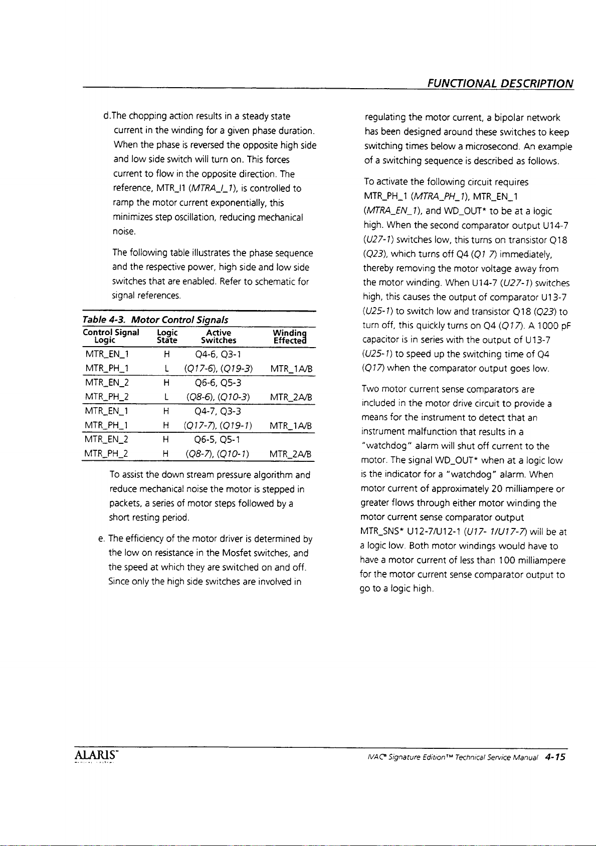
d.The
current
When
and
current
reference,
ramp
minimizes
noise.
The
and
switches
signal
Table
4-3.
Control
Signal
Logic
MTR EN
MTR_PH_1
MTR.
MTR_PH_2
MTR_EN_1
MTR_PH_1
MTR_EN_2
MTR_PH_2
1
EN
2
To
reduce
packets, a series
short
e.
The
the
the
Since
chopping
in
the
the
phase
low
side
switch
to
flow
MTR_I1
the
motor
step
foliowing
the
respective
that
are
references.
Motor
assist
efficiency
low
speed
Control
Logic
State
H
L
H
L
H
H
H
H
the
down
mechanical
resting period.
of
on
resistance
at
which
only
the
high
action
results
winding
oscillation,
table
for a given
is
reversed
will
turn
in
the
opposite
(MTRA_I_17),
current
exponentially,
illustrates
power,
enabled.
Signals
Active
Switches
Q4-6,
(017-6),
Q6-6,
(08-6),
Q4-7,
(О17-7,
Q6-5,
(08-7),
stream
noise
the
of
motor
the
motor
in
the
they
are
side
switches
reducing
high
Refer
(010-3)
(919-1)
Q5-1
(010-1)
pressure
steps
driver
in a steady
phase
the
opposite
on.
This
direction.
is
controlled
mechanical
the
phase
side
and
to
schematic
Q3-1
(019-3)
Q5-3
Q3-3
algorithm
motor
is
followed
is
determined
Mosfet
switched
switches,
are
involved
state
duration.
high
forces
The
this
sequence
low
Windin
Effected
MTR
MTR_2A/B
MTR_1A/B
MİR
2A/B
stepped
by
on
and
side
to
side
for
1A/B
and
in
a
by
and
off.
in
regulating
has
switching
been
the
designed
times
of a switching
To
activate
MTR
(MTRA
high.
(U27-1)
(023),
thereby
the
motor
high,
(U25-1)
turn
capacitor
(U25-1)
(Q17)
Two
included
means
instrument
“watchdog”
motor.
is
the
motor
greater
motor
MTR
SNS*
a
logic
have a motor
for
the
go
to a logic
the
PH 1 (MTRA
EN
1),
When
the
switches
which
removing
winding.
this
causes
to
switch
off,
this
is
in
to
speed
when
the
motor
current
in
the
for
the
malfunction
alarm
The
signal
indicator
current
flows
current
U12-7/012-1
low.
Both
motor
high.
FUNCTIONAL
motor
current, a bipolar
around
below a microsecond.
sequence
following
PH
and
WD
second
low,
turns
off
the
When
the
low
quickly
series
up
comparator
sense
motor
instrument
will
WD_OUT*
for a “watchdog”
of
approximately
through
sense
comparator
motor
current
current
these
is
described
circuit
1),
MTRLEN
OUT*
comparator
this
turns
04
(01
motor
U14-7
output
of
and
transistor
turns
on
with
the
the
switching
comparators
drive
circuit
to
that
shut
off
either
(U17-
windings
of
less
than
sense
comparator
voltage
Q4
output
output
detect
results
when
motor
DESCRIPTION
network
switches
An
as
follows.
requires
1
to
be
at a logic
output
on
transistor
7)
immediately,
away
(U27-1)
comparator
(Q77). A 1000
time
to
current
alarm.
20
output
1/U17-7)
would
100
switches
Q18
(Q23)
of
U13-7
of
goes
low.
are
provide
that
an
in
a
to
at a logic
When
milliampere
winding
will
have
miliiampere
output
to
keep
example
U14-7
Q18
from
U13-7
to
pF
Q4
a
the
low
or
the
be
at
to
to
ルル
4C
Signature
Edition™
Technical
Service
Manual
4-15

FUNCTIONAL
DESCRIPTION
Figure
4-9
Motor
Drive
Circuit,
MTR
(MTRA
Phase
M
1)
1
A
MTR
(MTRA
U13-7
VIA
1(A)
(U27)
、U14
ト
018
PHASE
1
PH
1)
PH
(U25-1)
(026)
Q19
PHASE
(023)
A
1A
MTR
(MTRA
A*
I
SA)
|
4
MOTOR
a
\
SENSE
RESISTOR
pe
(017)
04
Was
tara)
|
A
COIL
|
X
。
MTR_1B
(MTRA_1B)
|
017
(025)
PHASE
(024)
016
PHASE
|
>
U12
SENSE
COMPARATORS
A*
A
MTR
(U17)
SNS“
Figure
4-10
Motor
and
wo_our
Combo
PWM
Combo
Digital
Output
Mechanism
IC
IC
Output
Sensors
MOTOR_CURRENT_1
MOTOR
Block
CURRENT
MOTOR_PHASE_1_AB
MOTOR
PHASE 2 MB
MOTOR
EN 1 A8
MOTOR
EN 2 MB
moror
agen | Mechanism
LATCH
FLAG
2
AB
NB
EX
Diagram
Shutdown
Constant
Current
Motor
Driver
Motor
Current
Sense
|
Sensor
Mechanism
Sensor
MOTOR
COM
14
AB
48
18
COR
MOTOR
MOTOR
CON.
2A
AB
MOTOR
COR
28
AG
MOTOR
CURRENT
—
MOTORFACAS
LATCH
FLAG
AB
si
Motor
Stepper
Cale
.
Combo
Digital
IC
Input
IVAC
Signature
Edition™
Technical
Service
Manual
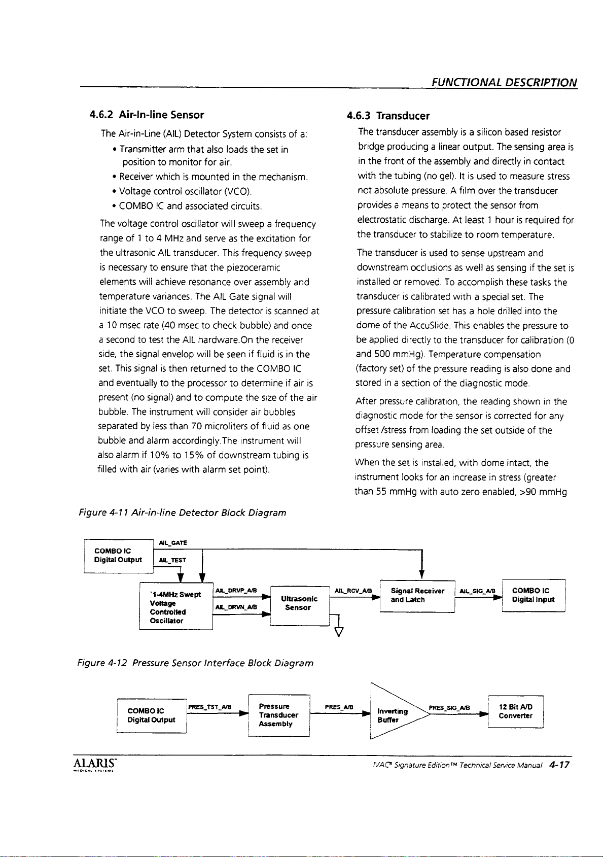
4.6.2
Air-In-line
The
Air-in-Line
*
Transmitter
position
e
Receiver
¢
Voltage
*
COMBO
The
voltage
range
of 1 to 4 MHz
the
ultrasonic
is
necessary
elements
temperature
initiate
a
10
msec
a
second
side,
the
set.
This
and
eventually
present
bubble.
separated
bubble
also
alarm
filled
with
control
to
will
the
VCO
rate
to
test
signal
signal
(no
signal)
The
instrument
by
and
alarm
if
air
Sensor
(AIL)
Detector
arm
that
to
monitor
which
is
mounted
control
variances.
less
10%
(varies
oscillator
IC
and
associated
oscillator
and
AIL
transducer.
ensure
that
achieve
resonance
to
sweep.
(40
msec
the
AIL
envelop
is
then
returned
to
the
processor
and
than
70
accordingly.The
to
15%
with
System
also
loads
for
air.
in
(VCO).
circuits.
will
serve
as
This
the
piezoceramic
over
The
AIL
Gate
The
detector
to
check
hardware.On
will
be
seen
to
to
to
compute
will
consider
microliters
of
downstream
alarm
set
consists
the
the
sweep a frequency
the
excitation
frequency
assembly
signal
bubbie)
the
if
fluid
the
COMBO
determine
the
air
of
instrument
point).
of
a:
set
in
mechanism.
for
sweep
and
will
is
scanned
and
once
receiver
is
in
the
IC
if
air
size
of
the
bubbles
fluid
as
one
will
tubing
at
is
air
is
4.6.3
Transducer
The
transducer
bridge
producing a linear
in
the
front
with
the
tubing
not
absolute
provides a means
electrostatic
the
transducer
The
transducer
downstream
installed
transducer
pressure
dome
be
and
(factory
stored
After
diagnostic
offset
pressure
When
instrument
than
or
calibration
of
the
applied
500
mmHg).
set)
in a section
pressure
/stress
sensing
the
set
55
mmHg
directly
mode
FUNCTIONAL
assembiy
of
the
assembly
(no
gel).
pressure. A film
to
protect
discharge.
to
is
occlusions
removed.
is
calibrated
AccuSlide.
of
the
calibration,
from
is
installed,
looks
with
At
stabilize
used
to
as
To
with a special
set
has a hole
This
to
the
Temperature
pressure
of
the
for
the
sensor
loading
area.
for
an
increase
auto
is a silicon
output.
It
and
is
used
over
the
The sensing
directly
to
the
sensor
least 1 hour
to
room
sense
upstream
well
as
sensing
accomplish
drilled
enables
transducer
compensation
reading
diagnostic
the
reading
is
corrected
the
set
outside
with
dome
in
stress
zero
enabled,
DESCRIPTION
based
resistor
area
in
contact
measure
transducer
temperature.
these
set.
the
for
is
also
mode.
shown
intact,
stress
from
is
reguired
and
if
the
set
tasks
the
The
into
the
pressure
calibration
done
in
the
for
any
of
the
the
(greater
>90
mmHg
is
for
is
to
(0
and
Figure
COMBO
Digital
Figure
MEDICAL
SYSTEMS
4-11
Air-in-line
IC
Output | AM
Controlled
4-12
Pressure
|
CoMBOIC
|
"9 Ρ
S
Detector
AL
GATE
TEST
<
、
14MHz
Swept | Z
Voltage
Oscillator
Sensor
ως
|
Interface
PRES
TST
Block
AL
DRVP
(EPA,
AB
Diagram
AB
py | conic
AB
Block
Diagram
Pressure
|
Assembly
LS
Sensor
|
PRES
A/B
Signal
and
Inverting
|
Buffer
IVAC®
Signature
Receiver
Latch
一 一 一
Edition™
AL
SIG
A/B
Technical
COMBO
Digital
12
Bit
Converter
Service
Manual
IC
Input
AD
4-17
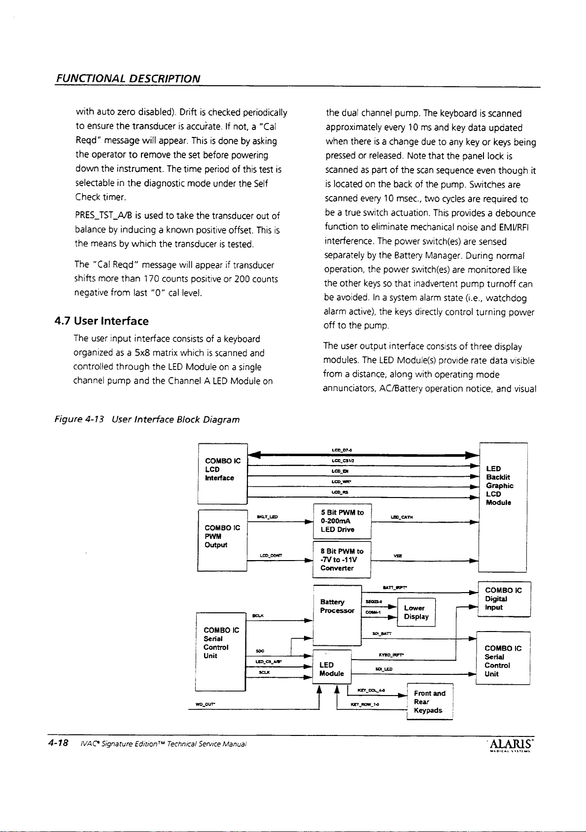
FUNCTIONAL
with
auto
to
ensure
Reqd”
message
the
operator
down
the
selectable
Check
timer.
PRES
TST
balance
the
means
The
“Cal
shifts
more
negative
4.7
User
interface
The
user
organized
controlled
channel
DESCRIPTION
zero
disabled).
the
transducer
will
appear.
to
remove
instrument.
in
the
diagnostic
A/B
is
used
by
inducing a known
by
which
the
Reqd”
message
than
170
from
last
“0”
input
interface
as a 5x8
through
pump
and
matrix
the
the
Drift
is
checked
is
accurate.
This
the
set
before
The
time
period
mode
to
take
the
positive
transducer
will
appear
counts
positive
cal
level.
consists
LED
Channel A LED
which
Module
of a keyboard
is
periodically
If
not, a "Cal
is
done
by
powering
of
this
under
the
transducer
offset.
is
tested.
if
transducer
or
200
scanned
on a single
and
Module
asking
test
is
Self
out
of
This
is
counts
on
the
dual
channel
approximately
when
there
pressed
scanned
is
located
scanned
be a true
function
interference.
separately
operation,
the
other
be
avoided.
alarm
active),
off
to
the
The
user
modules.
from a distance,
annunciators,
is a change
or
released.
as
part
on
the
every
switch
to
eliminate
The
by
the
the
power
keys
so
In a system
the
pump.
output
The
LED
AC/Battery
every
of
back
10
actuation.
interface
along
pump.
The
10
ms
due
Note
that
the
scan
of
the
msec.,
two
mechanical
power
switch(es)
Battery
that
keys
Manager.
switch(es)
inadvertent
alarm
directly
consists
Module(s)
with
operation
keyboard
and
to
any
the
sequence
pump.
cycles
This
state
control
provide
operating
is
scanned
key
data
key
or
panel
lock
even
Switches
are
required
provides a debounce
noise
and
are
sensed
During
are
monitored
pump
turnoff
(i.e.,
watchdog
turning
of
three
rate
mode
notice,
updated
keys
being
is
though
are
EMI/RFI
normal
like
power
display
data
visible
and
visual
it
to
can
Figure
4-13
User
Interface
Block
Diagram
COMBO
LCD
Interface
COMBO
PWM
Output
COMBO
;
Serial
|
Control
|
Unit
—
wo
our
LCD
IC
sarto
IC
p
=
LED
CONT
一
fa»,
>
IC
|
вск
500
LED,
sex
Se
—
na
>
>
„|
079
LCD_CS12
LCD
EN
ee
LOLAS
5
Bit
PWM
0-200mA
LED
Drive
8
Bit
PWM
-7Vto-11V
Converter
Battery
P
-
LED
Module
Á
|
KEY
FT
to
to
KE
en
ROW
so
==
COLO
ο
aren
77
Barr
YED
Leo
væ
>»
RET
cani
ー
Lower
Display
ge
Front
Rear
Keypads
LO!
and
3
o
a
PM,
pl
m
© | Module
>
>
je-
μα
>
>
|
|
|
LED
аи
Back
Graphic
LCD
COMBO
Digital
npu
COMBO
Serial
Control
Unit
IC
IC
IVAC*
Signature
Edition™
Technical
Service
Manual
“ALARIS
MLDICAL
SYSTEMS

alarm
indication.
user
information
LED
back
current
level
selected,
panel
lock
4.7.1
The
Main
main
voltage
exponentially
3)
modulated
kHz)
by
pulsed
at 3 to
100
mA).
provides
The
speaker
current
The
and
with a 0.5110
voltage
compared
on a 128x64
light.
The
battery
run
communications
status,
Speaker
speaker
speaker
the
up
drive
weighted 4 bit
at
the
COMBO
50
The
driver
to
3Vpp
is
tested
across
to
low
The
Graphic
Lower
time
along
and
battery
Driver
driver
is
chip,
desired
IC
U10
mA
with a 50%
has a fixed
AC
coupied
by
monitoring
resistor.
the
resistor
and
LCD
dot
LCD
display
with
interface
refresh
based
on
U32
(U29)
control
frequency
(U74).
26dB
into
is
amplified,
high
threshold
Module
matrix
shows
the
current
status.
an
LM386
driven
signal
(200
The
speaker
duty
cycle
gain
an
the
speaker
provides
display
the
audio
status,
low
by
an
(AMP 0 to
Hz - 4
is
(max.
which
80
speaker.
rectified,
values
by
with
a
window
tested
circuit
volume
Med=
4.7.2
À
allow
the
is
C146
linear
supply.
generator
to 4 kHz
(U41)
BKUP_ALARM_ARM
powered
will
comparator,
when
is
verified
settings
65
Backup
backup
the
event
Supplied
(C179) energy
regulator,
The
tone
powered
up
not
generate
FUNCTIONAL
an
alarm
at
power
are
dB,
and
Hi=
Audio
audio
generation
instrument
that
the
main
through
buzzer
and
U32
speaker
when
by
so
that
an
VBKUP, a 1.0
is a self
VBKUP
the
DESCRIPTION
U38
(U16).
The
speaker
or
error
occurs,
up.
The
speaker
approximately:
approx.
Buzzer
capability
to
generate
speaker
storage
(U44)
on
oscillating
module
energized. A logic
arms
signal
once
watchdog
alarm
if
70
dB.
and
an
is
Farad
device
the
VAO
which
the
the
WD_OUT*
the
unit
Low=
Test
is
audible alarm
unable
charged
audio
produces a 3
circuit
instrument
is
is
while
the
audio
min
45
Circuit
provided
to
do
“supercap”
by a 5V
SOURCE
circuit,
turned
U30
using
signal
on
test
dB,
to
so.
the
has
or
in
It
Figure
4-14
Main
COMBO
16
ui0
Speaker
|
(u14)
VTHRES
LOW
M
ul
AM
|_|
+
δι
AMPOTO3
270
59
mamp
R58
(R351)
0.514
OHM
È
ツ
U32
(U29)
GAIN = 37
Е
SPKR
POS
SPKR_NEG
VTHRES
HI
Sls
REAR
—-
COMPARATOR
Y
CASE
_
U38
(U16)
WINDOW
MAIN
SPEAKER
2KHz
MAIN_SPKR_TST
——
>
IVAC®
Signature
Edition®M
Technical
Service
Manual
4-19

FUNCTIONAL
off
properly.
power
switch(es)
main
CPU
control
The
is
drive
through
operation
waveform
The
whose
to
over
circuit
tested
the
buzzer
voitage
VTHRES
DESCRIPTION
Additional
to
turn
or
battery
the
has
at
power
buzzer
VBKUP_SRC_EN
is
tested
generated
current
Hi
processor
instrument.
two
test
up
to
when
by
sensing
by a normally
is
sampled
is
amplified.
by a comparator,
iogic
is
provided
off
the
no
functions.
verify
that
the
regulator
signal.
the
by à sense
The
DC
U33
to
backup
The
audio
longer
have
The
VBKUP
the
supercap
is
disabled
buzzer
oscillating
operating
resistor,
level
is
(U33),
allow
the
if
the
supply
can
current
buzzer.
compared
whose
4.8
output
the
LED
The
operating
notice,
have
The
along
to
The
to
(BKUP_SPKR_TST*)
COMBO
Module
LED
and
58
individual
IC
performs
with
the
main
LED
intensity
limit
power
IC.
Module(s)
mode
annunciators,
visual
alarm
LEDs
LED
keyboard
CPU
through
is
use
while
drives a digital
provide
controlled
rate
indication.
controlled
scanning
scanning
the
running
data,
along
AC/Battery
The
by a custom
and
test
circuits
local
by
serial
the
main
on
battery.
and
input
on
with
operation
modules
IC.
functions
interfaces
interface.
processor
Figure
4-15
Backup
VAO_SOURCE
DPM
VBKUP_SRC_EN*
ーーーーーーーーーーー
PWRSW_VBKUP
BKUP_ALARM_ARM
WD
OUT
一 参 =-
=
Audio
sy
U31
REG
(U44)
>
|
D
U37
DIGITAL
LOGIC
(U32)
VBKUP
4.9
+
C146
SUPER
1.0F
5.5V
U30
|
一
TO
5.1V
(C179)
CAP
(U41)
一
一
VTHRES
4)
Q12
-
HI
SUPER
MINUTES
FROM
(Q29)
SPKR2
3
TO 4 KHz
CAP
11
TAKES
TO
MIN
UP
CHARGE
TO 2 HOURS
BKUP_SPKR_TST*
TO
AND
30
LASTS
NA
4-20
IVAG
AMA
100
OHM
Signature
Edition"
GAIN = 14
Technical
Service
Manual
U33
(U33)

4.9
Lower
The
on
current
current
interface
refresh
and
AC.
Figure
4.10
The
a
main
mapped
the
find
100
the
on
main
through
6.4.16
4.10.1
The
by
by a PWM
current
200
on
amp
LCD
Lower
or
off,
AC
battery
audio
status,
status.
is
back
4-16
Lower
4»
TAYLAR
iv
E
Main
LCD
Main
LCD
128x64
dot
processor
form,
display
and
avoid
mSec.
The
main
processor
battery.
CPU
and
memory
The
the
“Changing
Main
graphic
an
adjustable
signal
can
be
mA
range.
resistance
to
set
the
Display
LCD
Display
or
battery
run
time
level
selected,
panel
lock
It
is
driven
lit
when
the
LCD
Display
»'M
た
還
matrix
diagnostics
LCD
LCD
FET,
站 四 四
123
Module
Module
display
generates
then
compares
to
that
problems.
back
light
to
limit
LCD
contrast
can
be
adjusted
Main
Back
backlight
constant
from
the
adjusted
The
current
0.5112
sense
resistor
provides
stepwise
is
visible
whether
operation.
available
communications
status,
by
the
Battery
pump
is
on
Layout
Çeri
ルー
MNTR
4
user
with
LED
all
text
and
data
which
was
Screen
updates
intensity
power
is
controlled
from
mode.
Refer
LCD
Contrast”.
Light
is
an
array
current
sense
source
COMBO
linearly
source
resistor,
voltage
the
it
shows
along
with
and
battery
Manager
or
plugged
0
hrs.
information
back
symbols
read
back
generated
occur
is
controlled
use
while
by
factory
to
Section
of
LEDs
controlled
IC.
The
LED
over a 0-
consists
and
based
of a low
on
pump
the
the
into
on
light.
The
in
bit
from
to
every
by
running
the
default
driven
op
the
is
filtered
intensity
4.10.2
The
Vneg
The
LCD
range.
be
software.
4.11
An
232/Nurse
relay
of
4.12
The
changes
shown
feature
panel
split
4.13
4.13.1
The
empty
Model
independent
detection
circuitry
and
detected.
is
4.13.2
a.
PWM
is
not
Graphic
graphic
drive
CONT
adjusted
Nurse
optional
contact
the
Panel
pump
screen
ECD
ECD
ECD
generates a ~20
not
used.
ECD
Overview
PC
board
optical
rejection
digital
sensor
2
separate
LCD
supply
to
circuit
signal
Nominally,
through
Cali
nurse
Call
on
RS-232
Lock
can
with
the
in
the
Lower
is
active.
keys
is
restricted
viewing
Board
Board
board
container
180
Drop
drop
circuits
can
detect
Note
Board
The
which
flow
sensor,
on
the
output
attached
ambient
FUNCTIONAL
input
voltage
user
adjustable.
LCD
Contrast
contrast
the
inverts
from
the
Circuit
call
board
system
connector.
Switch
be
protected
Panel
When
Option
(sold
detection
Sensors.
sensor
as
whether a drop
that,
Option
flow
drives a standard
resulting
signals
detection.
is
module
and
the
contrast
Configuration
(7100/7200
circuit
and
provides a 35V @ 1A
alarms
Lock
LCD
Display
activated,
(except
key).
in a separate
using
The
control
well
as
timing
ms
pulse
for
SE | use,
for
sensor
performs
signals,
for a detected
light
discriminator
DESCRIPTION
BKLT_LED.
controlled
over a -7V
scales
COMBO
voltage
the
IC
Mode
The
by
to
filtered
to
is
only)
is
located
through
from
Switch. A lock
channel
for
board
for
7101/7201
interface
ambient
The
on
pins 6 and
unauthorized
whenever
access
to
select
7100/7200
kit)
provides
standard
contains
circuits
the
control
sensor
each
drop
second
is a separate
IVAC
and
light
and
provides
drop
board
consists
loops
backlight
varying
-11V
range.
PWM
cover
-9V,
but
in
the
RS-
symbol
the
all
front
and
IVAC
two
drop
logic.
is
installed
channel
180
and
and
the
this
can
rated
9
is
The
of
ALARIS
MEDICAL
SYSTEMS
IVAC
Signature
Edition™
Technical
Service
Manual
4-21

FUNCTIONAL
drop
sensors
logic.
single
“B”
channel
ignored
instruments.
both
the
instrument
instrument,
opposite
.
Common
control
timing
sample
and
LED
The
main
timebase
non-overlapping
sense
load
and
operation.
inverted
c.
Ambient
sensor
normally
the
difference
sensor
Analog
output
room
ambient
When
the
sense
voltage
transferred
amplified
the
DROP
The
DROP_ASB
U1/U6
LED
drive
DESCRIPTION
detectors
The
and
logic
signals
signals
signals.
control
drive
when
multiplexor
of
the
less
and
for
along
with
board
dual
channel
is
not
in
the
software
Note
“A”
channel
as
well
even
sides
of
Timing
generates
to
representing
driven
light
system
and
decade
This
flow
sensor
Transistors
signals
Light
Discriminator
current
at
DROP.
in
input
the
emitter
the
sense
light
LED
drive
capacitor,
the
ambient
to
sample
by
U8/U7
A/B
signal.
signal
C9/C10
level
to
maintain
independent
common
assembly
is
instruments,
available
of
that
the
in
the
as
the
single
though
the
drive
case.
Logic
the
the
the
The
flow
outputs
CLK_32KHz
counter
“A”
and
“B”
reduces
A/B.
U4
signal
the
crosstalk
Q5
and
for
the
is
set
to
This
signal
is
undriven
normally
capacitor
voltage
is
turned
representing
signal
cap
C28/C26.
with a gain
is
sensed
to
generate
DROP_A/B
Mode!
180
timing
and
control
common
to
where
externally
the
single
“A”
dual
and
channel
channel
channel
is
channel
mechanisms
common
necessary
sensor
room
from
is
used
U3
channel
peak
during
Q6
LED
Loop
maintain a 2.8V
level
from a 180
grounds
C18/23
on,
voltage,
of
by
an
timing
discriminator
LED
ambient
the
flow
as
the
that
generates
drive
LED
current
normal
provide
drive
circuits.
The
is
determined
drop
and
driven.
the
so
that
is
set
across
the
output
the
driven
is
This
signal
about
23
integrator
appropriate
at
about
flow
both
the
is
used
for
are
on
and
and
light
sensor.
and
logically
flow
level
by
it.
of
signal
is
and
is
2.8V.
The
integrator
drive
enable
FET
current
constant
current
To
drive
of
a
.
Drop
generates a digital
is
passes
Model
negative
DROP_A/B
generate a 0
of
shots
which
The
stream
occurring
and
EMC
energy
pins.
.
Option
The
signal
The
ECD_INSTALLED
low
sensor
monitoring
collector
the
they
the
sink
U1/Q4
current
with a OV-1V
prevent a drop
signal, a long
CR1/CR2,
negative
detected. A drop
appropriate
U9A/B
main
operating
filtering
installed
on
main
signal
voltage
drop
collector
R31/R13,
going
Detector
between
180
drop
going
short
signal.
to
length
generate a nominal
indicates a valid
system
and
determines
properly
mode
is
provided
into
or
out
Installed
option
pin 7 of
processor
if
the
installed
signals
the
LED
voltage.
and
generate a 5V
below
voltage
output
Q1/Q2
to
and
related
source
generates a 0-200mA
input
even
from
time
constant
and
output
signal
The
drop
pulse
when a valid
event
occurs
the
emitter
sensor
and
duration
Detector
5V
pulse
when a drop
and
duration
drop
processor
whether
for
the
current
(i.e.
primary/secondary).
by
of
the
flow
and
Sensor
detection
J3
tied
to
has a pulldown
signal
which
option
is
not
are
generated
current
Comparator
about
1.7V.
should
signal
is
drive
the
components.
controlled
LED
by
constant
The
sink
signal.
skewing
C9/C10,
detector
and
appears
pulse
comparators
(ECD-SIG-AVECD-SIG-B).
processes
filters
wensor
Installed
consists
+5V
generates a logic
installed.
sink
U2A/U2B
output
Note
not
the
LED
filter,
consisting
is
enabled
DROP
A/B.
circuit
drop
when a fluid
detector
20
the
instrument
C4-8
of
as a generally
on
the
U8B/U7B
“signature”
occurs.
ms
pulse
the
pulse
drops
are
to
limit
connecxtion
Circuit
of
the
on
the
board.
resistor
Flow
by
drive
transistor
monitor
signal
that,
nominally,
go
below
about
event
drop
the
One
rate
input
on
the
if
on
4-22
VAC
Signature
Edition™
Technical
Service
Manual

Figure
2.2V
with a flow
maximum
4-17
Flow
sensor
current.
Sensor
attached
Interface
Drop
AB
and
Block
driven
Diagram
+SV
A
Model-180
at
Flow
Sersor
FUNCTIONAL
DESCRIPTION
ν
A
curar
uve
Integrator
i
Timing
Logic
Constant
mm
U1Q4
Current
Sink
A
トー
トー
に
3
一
A
U7B/U88
Drop
Detector
W“
|E0.56
48
—
ECD_INSTALLED
ECD A ACTIVE
vana
[One
Combo
IC
MEDICAL
SYSTEMS
VAC
Signature
Edition™
Technical
Service
Manual
4-23

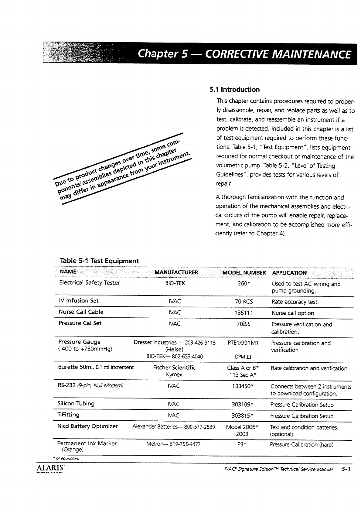
Chapter
5
—
CORRECTIVE
5.1
Introduction
This
chapter
ly
disassemble,
test,
calibrate,
problem
of
test
tions.
required
volumetric
Guidelines”,
repair.
A
thorough
operation
cal
circuits
ment,
ciently
contains
repair,
and
is
detected.
equipment
Table
for
pump.
5-1,
“Test
normal
Table
required
provides
familiarization
of
the
mechanical
of
the
pump
and
calibration
(refer
to
Chapter
MAINTENANCE
procedures
and
reassemble
Included
Equipment”,
checkout
5-2,
tests
with
will
to
be
4).
required
replace
to
parts
an
instrument
in
this
chapter
perform
lists
or
maintenance
“Level
of
for
various
the
function
assemblies
enable
accomplished
repair,
as
these
equipment
Testing
levels
and
to
proper-
well
as
if
a
is a list
func-
of
the
of
and
electri-
replace-
more
effi-
to
EOC
Table
NAME
Electrical
IV
Nurse
Pressure
Pressure
(-400
Burette
RS-232
Silicon
T-Fitting
Nicd
Permanent
(Orange)
*
or
equivalen:
AS
SYSTEMS
5-1
Safety
Infusion
Call
Cal
Gauge
to
+750mmHg)
50m,
(9-pin,
Tubing
Battery
Test
Equ
s
Tester
Set
Cable
Set
0.1
mi
Null
Modem)
Optimizer
ink
Marker
ipment
increment
Alexander
MANUFACTURER
Dresser
Industries
BIO-TEK—
Fischer
Metron—
BIO-TEK
МАС
IVAC
МАС
—
(Heise)
802-655-4040
Scientific
Kymex
IVAC
IVAC
IVAC
Batteries—
619-755-4477
203-426-3115
800-577-2539
-
MODEL
PTE1/901M1
Class
113
303109*
30368153
Model
IVAC
NUMBER
260*
70
RCS
136111
70155
DPM
IH
A
or
Sec
A*
133450*
2006”
2003
P3*
Signature
APPLICATION
Used
pump
Rate
Nurse
Pressure
calibration.
Pressure
verification
By
Rate
Connects
to
Pressure
Test
(optional)
Pressure
Edition™
to
grounding.
accuracy
call
calibration
download
Calibration
ressure
Calibration
and
condition
Caiibration
Technical
.
test
AC
wiring
test.
option
verification
calibration
between
configuration.
Service
and
and
and
verification.
2
instruments
Setup
Setup.
batteries.
(hard)
Manual
and
5-1
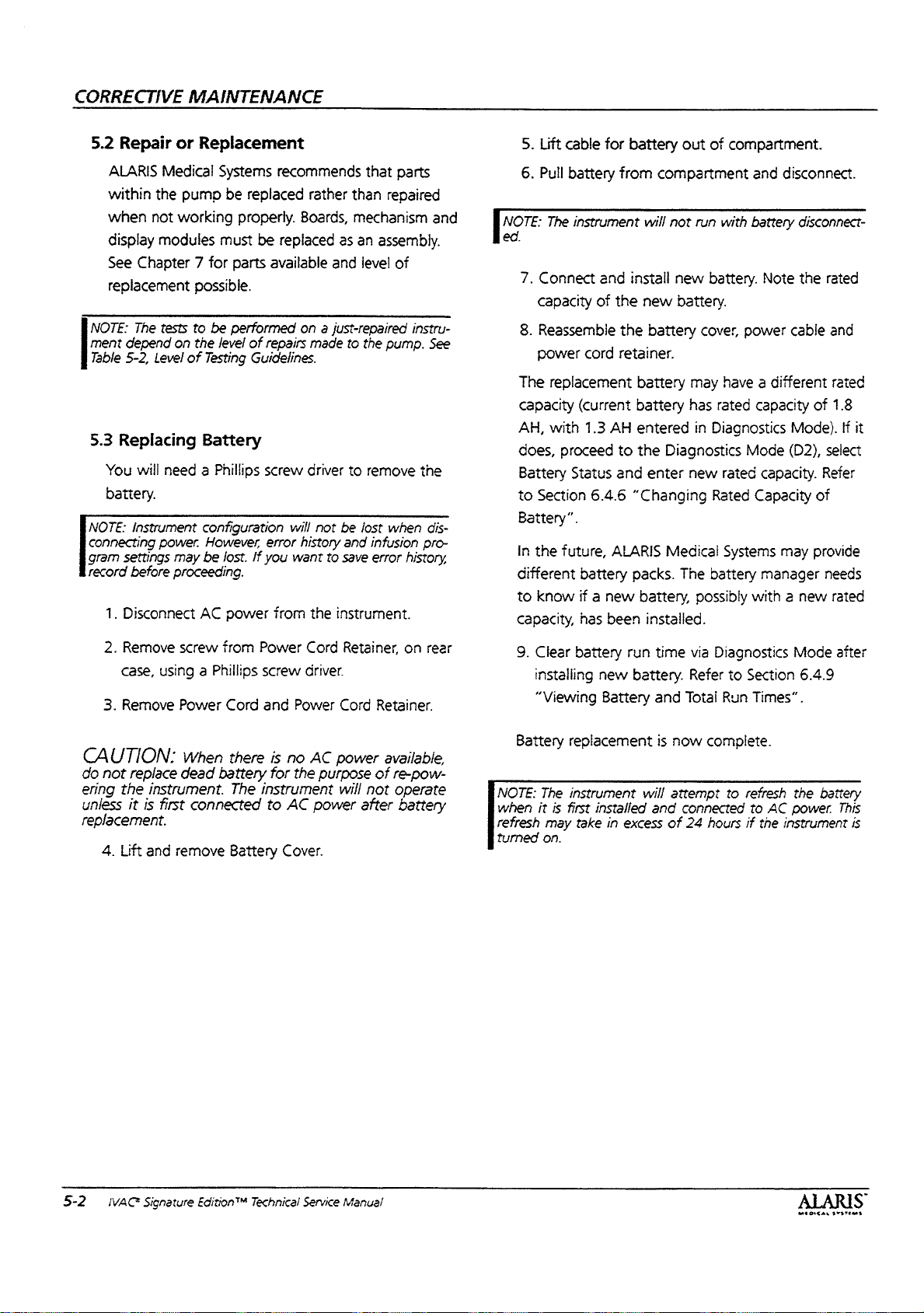
CORRECTIVE
5.2
Repair
MAINTENANCE
or
Replacement
5.
Lift
cable
for
battery
out
of
compartment.
ALARIS
within
when
display
See
Chapter 7 for
replacement
NOTE:
The
ment
depend
Table
5-2,
5.3
Replacing
You
will
battery.
NOTE:
instrument
connecting
gram
settings
record
before
1.
Disconnect
Medical
the
not
modules
Systems
pump
be
working
must
replaced
properly.
parts
possible.
tests
to
be
the
of
Testing
performed
level
of
on
Level
Battery
need a Phillips
configuration
power.
However,
may
be
AC
lost.
power
proceeding.
recommends
rather
Boards,
be
replaced
available
on a just-repaired
repairs
screw
will
error
you
want
from
made
driver
not
history
the
Guidelines.
If
that
than
repaired
mechanism
as
an
assembly.
and
level
of
to
the
pump.
to
remove
be
lost
when
and
infusion
to
save
error
instrument.
parts
and
instru-
See
the
dis-
pro-
history,
6.
[лоте
ed.
7.
8.
The
capacity
AH,
does,
Battery
to
Battery”.
in
different
to
capacity,
Pull
battery
The
instrument
Connect
capacity
and
of
Reassemble
power
cord
replacement
(current
with
1.3
proceed
Status
Section
the
6.4.6
future,
battery
know
if a new
has
from
will
instali
the
new
the
battery
retainer.
battery
battery
AH
entered
to
the
and
enter
“Changing
ALARIS
packs.
battery,
been
installed.
compartment
not
run
new
and
with
battery
battery.
battery.
cover
power
may
have a different
has
rated
in
Diagnostics
Diagnostics
new
Mode
rated
Rated
Capacity
Medical Systems
The
battery
possibly
with a new
disconnect.
disconnect-
Note
the
cable
capacity
of
Mode).
(D2),
capacity.
may
provide
manager
rated
and
rated
1.8
If it
select
Refer
of
needs
rated
2.
Remove
case,
using a Phillips
3.
Remove
CAUTION:
do
not
replace
ering
the
instrument.
unless
it
is
Lift
and
first
replacement.
4.
screw
from
Power
Cord
When
dead
battery
connected
remove
Power
screw
and
there
is
for
The
instrument
to
Battery
Cord
driver.
Power
no
AC
the
purpose
AC
power
Cover.
Retainer,
Cord
Retainer.
power
available,
of
will
not
after
on
rear
re-pow-
operate
battery
9.
Battery
NOTE:
when
refresh
turned
Clear
battery
installing
“Viewing
new
Battery
replacement
The
instrument
it
is
first
may
on.
installed
take
in
run
time
battery.
and
is
now
will
attempt
and
excess
of
via
Diagnostics
Refer
to
Total
Run
complete.
to
connected
24
hours
Section
Times”.
refresh
to
AC
if
power.
the
instrument
Mode
6.4.9
the
battery
after
This
is
5-2
IVAC
Signature
Edition™
Technical
Service
Manual
MA を の
いで
てろ い うと る aa
る

CORRECTIVE
MAINTENANCE
Power
(removed
RS232
Cord
Retainer/Battery
to
access 2 case
Tamper
Flow
Cover and
Power
Handle
Sensor
Connector.
Power
Cord
Retainer
Cover
Battery
Pole
Cover
screws)
—
Switch
Plugs
Cord—
Screw
Cover
Clamp
RC
EU
αν
AN
MEDICAL
SYSTEMS
Case
Battery
Screws
Battery
Cover
(9)
—
——
A
|
M
IVAC
©
Signature
Edition™
Technical
Service
Manual
5-3

CORRECTIVE
5.4
Disassembling
Gaining
the
necessary
a
Organization”,
hierarchy.
drawings. A more
disassemble
You
wrench,
allen
sernble
NOTE:
connecting
tings
before
access
pump
component.
will
need a Phillips
3/8”
driver
the
Instrument
power.
may
be
proceeding.
MAINTENANCE
the
and
removing
for
replacement
to
disassemble
Figure
5-1,
provides
Also
refer
to
detailed
the
instrument
socket
to
pump.
lost.
wrench,
separate
configuration
However,
If
you
want
Pump
various
is
simple.
the
entire
pump
“Instrument
the
instruments
Chapter 7 for
description
follows.
screw
driver,
3/16”
and
3/32”
both
case
halves
will
not
and
save
be
programmed
event
history
to
components
It
may
not
to
replace
Assembly
assembly
assembly
on
how
to
socket
(or
2.5
and
disas-
lost
when
log,
record
of
be
mm)
dis-
set-
WARNING:
before
when
of
disassembling.
AC
power
the
POWER
CAUTION:
assemblies,
static
grounding
Disconnect
is
switch.
10
use
extreme
techniques.
Hazardous
connected
avoid
serious
care
pump
regardless
from
voltages
damage
and
always
of
to
AC
are
the
the
use
power
present
setting
board
proper
Though a dual
lowing
the
single
Figure
procedures,
same
manner.
channel
5-1.
INSTRUMENT.
channel
instrument.
Instrument
pump
both
Channel B will
„Front
/
;
\
\
\
Rear
is
depicted
instruments
Assembly
Case
Case
disassemble
be
the
Organization
Half
£--
x
/
グ
„Speaker
Half を に - --Battery
No
in
the
fol-
in
same
as
a
Main
PCB
Mechanism
Main
¿Pole
Panel
“Fan
Keypad
Clamp
Lock
„---
~~
.
(All,
Switch
Lower
マー
LATCH
LCD
and
pressure
sensor
included)
5-4
IVAC
Signature
Ecition™
Technical
Service
\RS-232
\
‘AC
Manual
Off
Board
Line
-----
.
Switcher
AC
.
-------------
Line
Filter
<.
_->Heat
sink---Heat
Sink
MÉDICAL
Seal
<
YATES
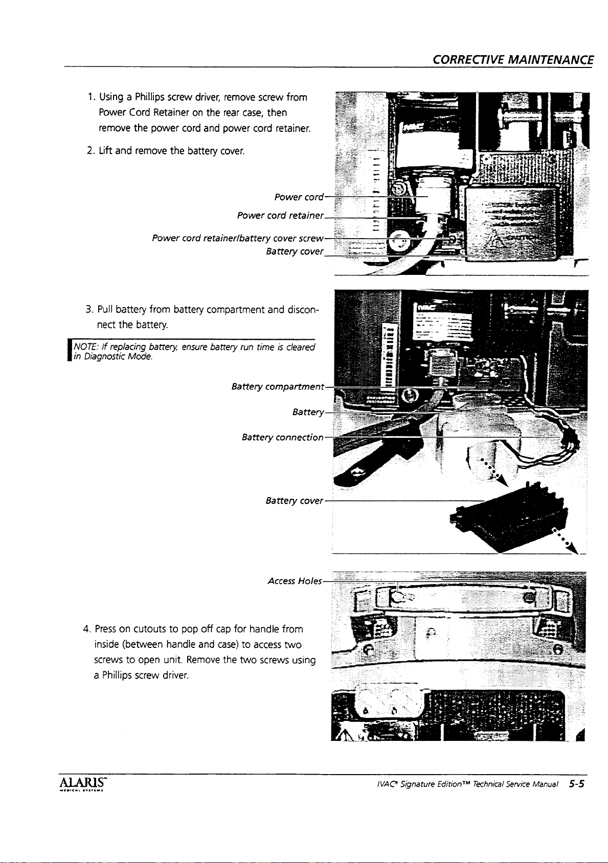
1.
Using a Phillips
Power
Cord
remove
2.
Lift
and
the
remove
screw
Retainer
power
cord
the
Power
cord
driver,
remove
on
the
rear
and
power
battery
cover.
Power
retainer/battery
screw
case,
cord
from
then
retainer.
Power
cord
retainer
cover
Battery
cord
screw
cover
41111
ΑΡΗ
fiat
CORRECTIVE
MAINTENANCE
3.
[noz
in
Diagnostic
Pull
battery
nect
the battery.
If
replacing
Mode.
from
battery
battery,
ensure
compartment
battery
run
Battery
Battery
time
and
discon-
is
cleared
compartment
Battery
connection
Battery
Access Holes
cover
MEDICAL
4.
Press
inside
screws
a
SYSTEMS
on
cutouts
(between
to
Phillips
screw
open
to
pop
handle
unit.
Remove
driver.
off
and
cap
for
case)
the
handie
to
access
two
from
two
screws
using
IVAC
Signature
Edition™
Technical
Service
Manual
5-5
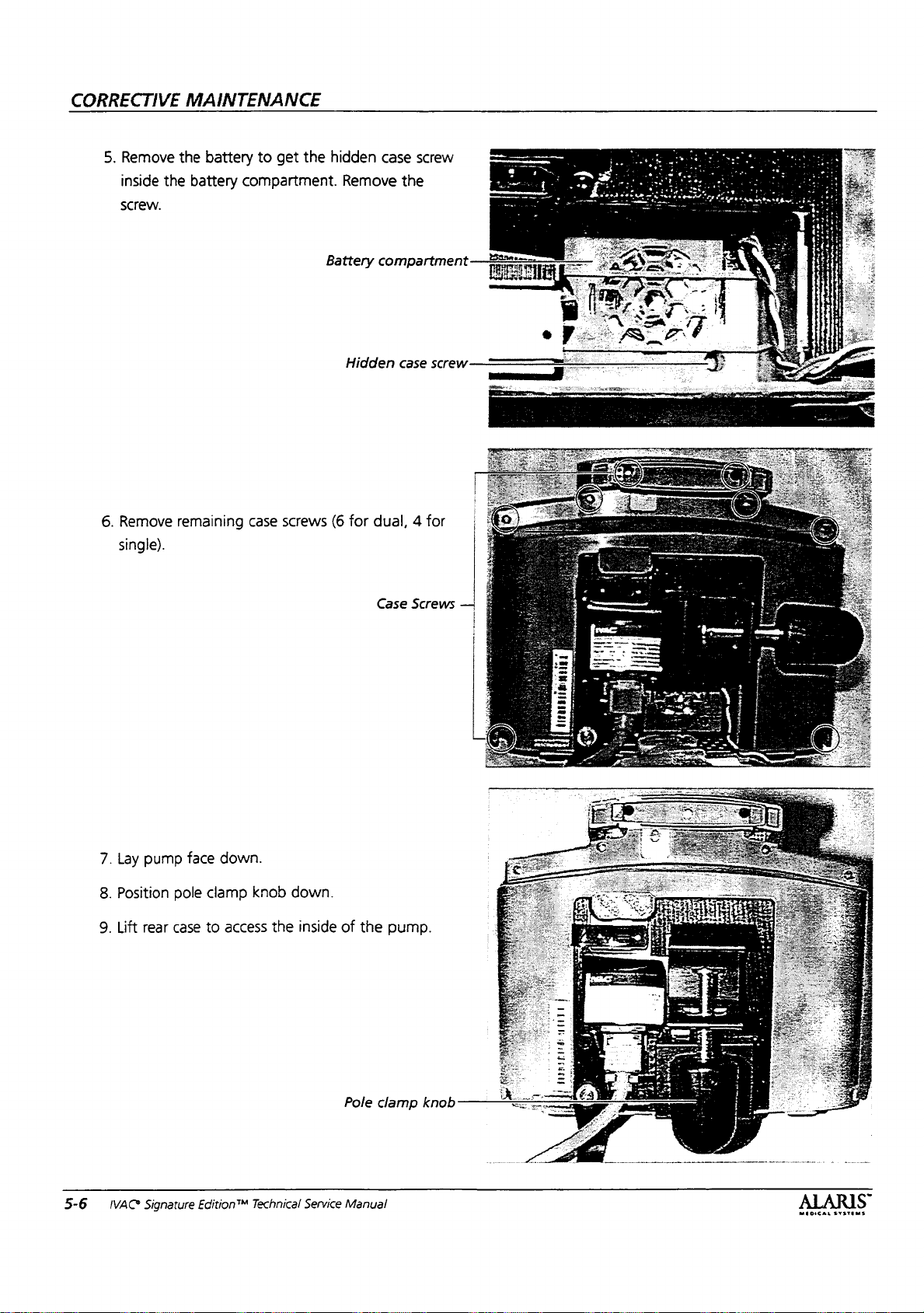
CORRECTIVE
5.
Remove
inside
screw.
MAINTENANCE
the
battery
the
battery
to
get
the
hidden
compartment.
Battery
case
screw
Remove
the
compartment-—22
=
Ee
6.
Remove
single).
remaining
case
screws
(6
for
dual, 4 for
Case
Screws
—
5-6
7.
Lay
8.
Position
9.
Lift
IVAC
pump
face
pole
rear
case
Signature
Edition”
down.
clamp
to
access
knob
down.
the
inside
Technical
Service
of
the
Pole
Manual
pump.
clamp
4
р
|
A:
MHOICAL
SYSTEMS
knob
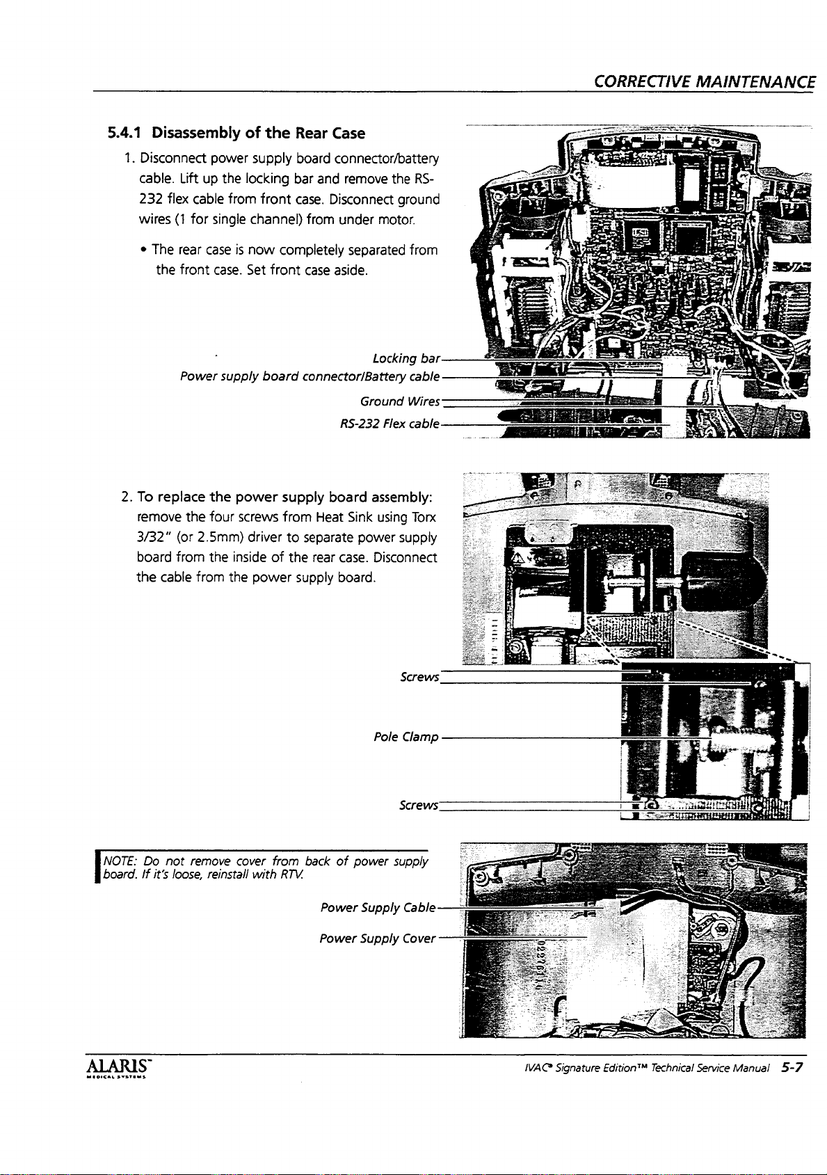
CORRECTIVE
MAINTENANCE
5.4.1
1.
Disconnect
cable.
232
wires
©
2.
To
remove
3/32"
board
the
Disassembly
power
Lift
up
the
flex
cable
from
(1
for
single
The
rear
case
the
front
case.
Power
supply
replace
cable
the
(or
2.5mm)
from
from
the
four
the inside
the
of
the
supply
locking
front
channel)
is
now
Set
front
board
power
screws
driver
of
power
Rear
Case
board
connector/battery
bar
and
remove
case.
Disconnect
from
under
completely
case
connector/Battery
supply
from
to
separate
the
supply board.
aside.
board
Heat
rear
separated
RS-232
Sink
power
case.
the
ground
motor.
from
Locking
cable
Ground
Wires
Flex
cable
assembly:
using
Torx
supply
Disconnect
y
1020”
am
ee
aa
RTE
NE
RS-
bar
NOTE:
board.
Do
If
not
it’s
loose,
remove
reinstall
cover
with
from
RTV.
back
Power
Power
of
Pole
power
Supply
Supply
Screws
Clamp
Screws
supply
Cable
Cover
a
SENO:
Sá
a
sé
vw
ie
y
|
MEOICAL
SYSTEMS
S
IVAC
Signature
EditionTM
Technical
Service
Manual
5-7
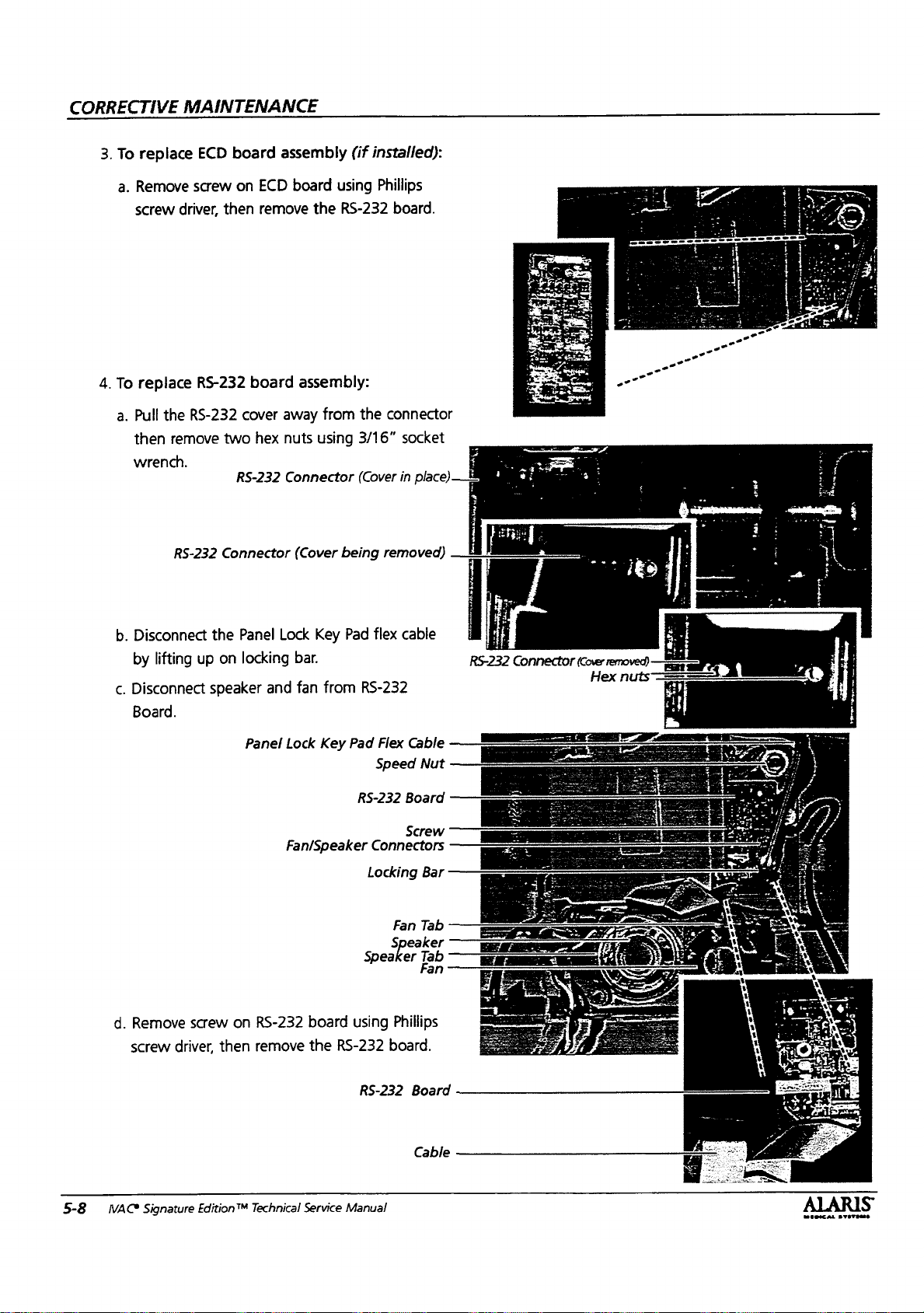
CORRECTIVE
3.
To
replace
a.
Remove
screw
4.
To
replace
a.
Pull
then
wrench.
MAINTENANCE
ECD
board
screw
on
driver,
then
RS-232
the
RS-232
remove
cover
two
RS-232
assembly
ECD
remove
board
away
hex
nuts
board
using
the
assembly:
from
using
Connector
(if
installed):
Phillips
RS-232
the
connector
3/16”
(Cover
board.
socket
in
place)
*8
RS-232
b.
Disconnect
by
lifting
.
Disconnect
c.
Board.
Connector
the
up
on
speaker
Panel
Lock
locking
and
Panel
Lock
Fan/Speaker
(Cover
Key
bar.
from
fan
Key
being
Pad
flex
RS-232
Pad
RS-232
Connectors
Locking
Speaker
removed)
cable
Flex
Cable
Speed
Board
Screw
Fan Tab
Speaker
(o № ii
Nut
Bar
Tab
Fan
pi
RS-232
=
:
Connector
(Cover
removed)
Hex
nuts
se
4
5-8
d.
WACS
Remove
screw
Signature
screw
driver,
then
Edition™
on
RS-232
remove
Technical
board
the
RS-232
Service
using
RS-232
Manual
Phillips
board.
Board
Cable
moore:
SYSTE

CORRECTIVE
MAINTENANCE
5.
To
replace
Line
Filter
Remove
tor
using
Remove
assembly.
6.
To
replace
and
remove
Disconnect
the
line
using
Phillips
two
screws
Phillips
exterior
screw
power
speaker/fan
the
fan
from
RS-232
filter:
screw
from
exterior
driver.
connector
assemblies:
or
speaker.
Board,
remove
driver.
power
Line
if
necessary.
screw
and
spread
from
connec-
Line
Filter
Line
Filter
Filter
Screw
clips
——:
7.
To
inside
Remove
replace
the
rear
the
the
Heat
Heat
case
using a 3/8”
Sink.
Sink:
remove
socket
Speaker
speed
wrench.
Speed
Heat
Line
Fan
Clip
Speaker
Clip
Fan
nuts
Nuts
Sink
Filter
Disassembly
MEDICAL
SYSTEMS
of
the
rear
case
is
now
complete.
IVAC
Signature
Edition™
Technical
Service
Manual
5-9
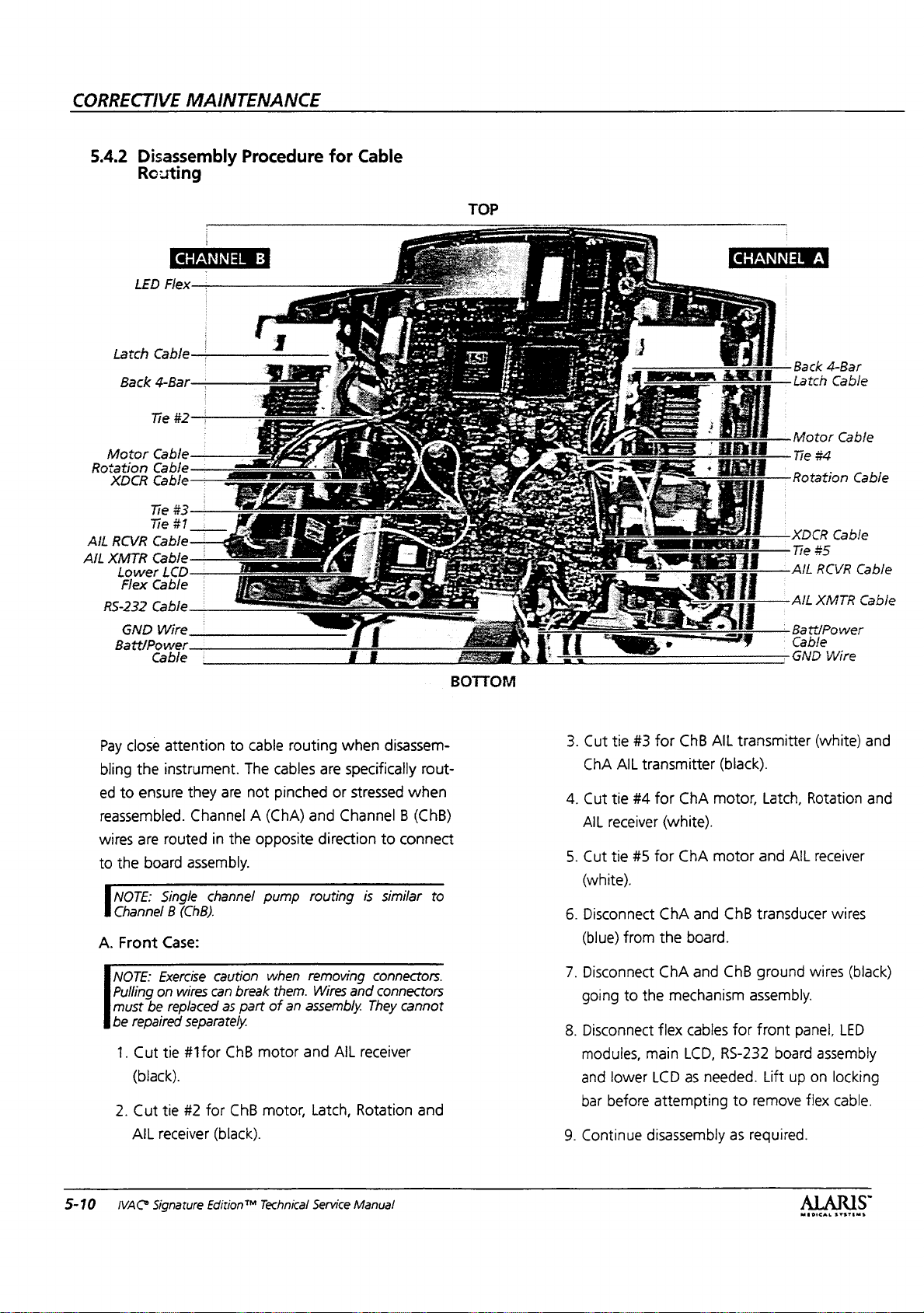
CORRECTIVE
MAINTENANCE
5.4.2
Disassembly
Routing
LED
Flex—
Latch
Cable
Back
4-Bar
Tie
Motor
XDCR
Cable
Cable
Cable
Rotation
Flex
Cable
RS-232
Cable
GND
Wire
Batt/Power
Cable
Procedure
CHANNEL
B
#2—
:
.
for
Cable
BOTTOM
Back
4-Bar
Latch
Cable
Motor
Cable
—
Tie
$4
Rotation
_XDCR
Tie
AIL
AIL
-
Batt/Power
Cable
-GND
Cable
$5
RCVR
XMTR
Wire
Cable
Cable
Cable
Pay
bling
ed
reassembled.
wires
to
NOTE:
Channel B (ChB).
A.
NOTE:
Pulling
must
be
2.
5-10
close
the
ensure
to
are
the
board
Front
Exercise
on
be
repaired
1.
Cut
(black).
Cut
AIL
receiver
IVAC?
Signature
cable
attention
instrument.
routed
Single
Case:
to
The
not
are
they
Channel A (ChA)
in
the
assembly.
channel
caution
wires
can
for
break
as
part
ChB
ChB
replaced
separately.
tie
#1for
#2
tie
(black).
Edition™
routing
cables
pinched
and
opposite
pump
routing
when
removing
them. Wires
of
an
assembly.
motor
and
motor,
Technical
Latch,
Service
disassem-
when
specifically
are
stressed
or
Channel B (ChB)
direction
to
is
similar
connect
connectors.
and
connectors
They
cannot
AIL
receiver
Rotation
Manual
rout-
when
to
and
tie
Cut
3.
AIL
ChA
tie
Cut
4.
AIL
receiver
5.
Cut
tie
(white).
6.
Disconnect
from
(blue)
7.
Disconnect
going
to
8.
Disconnect
modules,
and
lower
before
bar
9.
Continue
AIL
ChB
for
#3
transmitter
ChA
for
#4
(white).
#5
for
ChA
motor
ChA
and
board.
the
ChA
the
main
and
mechanism
flex
cables
LCD,
LCD
as
needed.
attempting
disassembly
transmitter
(black).
motor,
Latch,
and
ChB
transducer
ChB
ground
assembly.
for
front
RS-232
Lift
remove
to
as
required.
board
(white)
Rotation
AIL
receiver
wires
panel,
assembly
up
on
flex
MEDICAL
and
and
wires
(black)
LED
locking
cable.
-
SYSTEMS
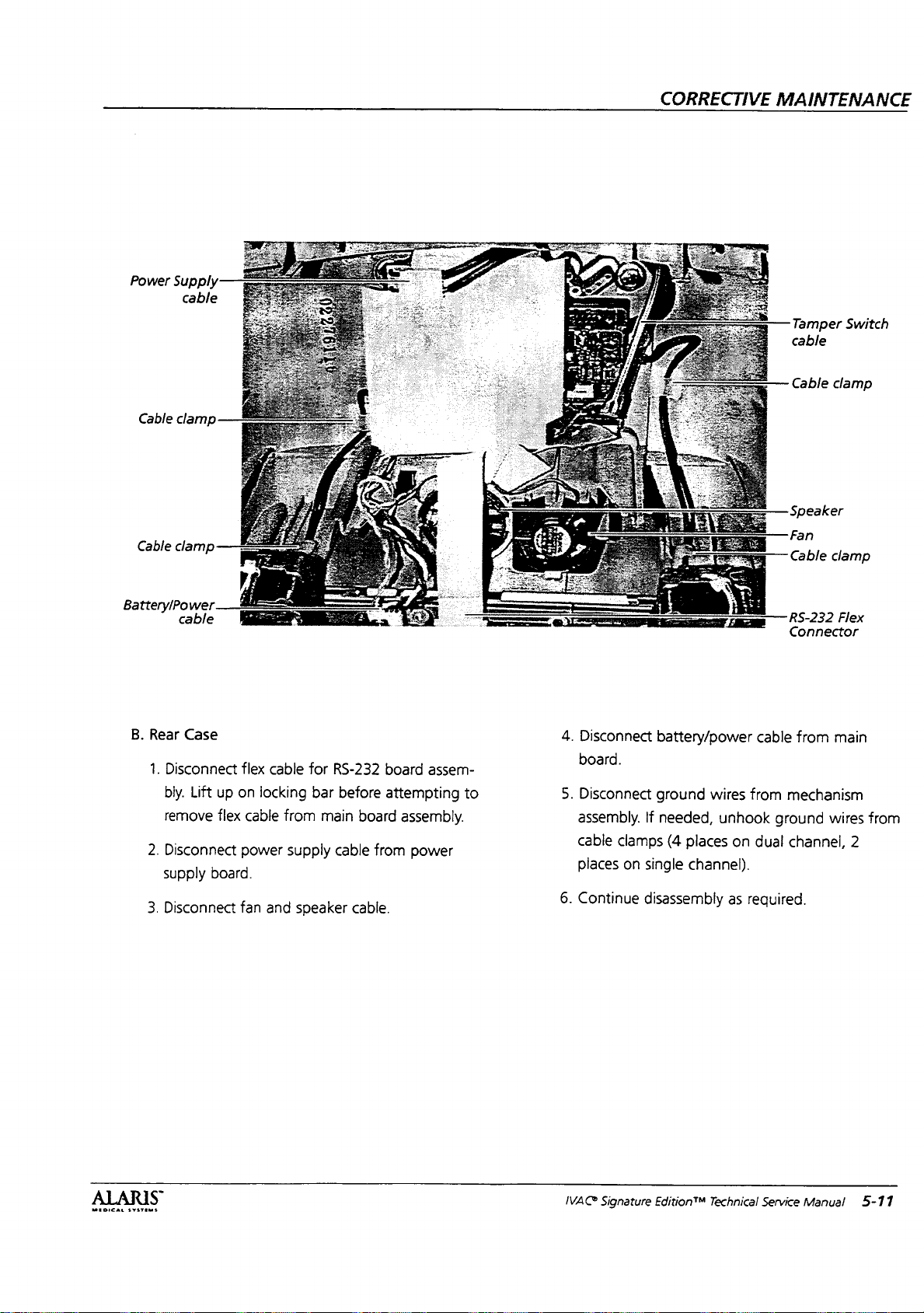
Power
Cable
Cable
Supply
cable
clamp
clamp
CORRECTIVE
MAINTENANCE
Tamper
cable
Cable
Speaker
Fan
Cable
Switch
clamp
clamp
tteryiP,
BatteryiPower
B.
Rear
Case
1.
Disconnect
bly.
Lift
remove
2.
Disconnect
supply
3.
Disconnect
flex
up
on
flex
cable
power
board.
fan
locking
cable
from
supply
and
speaker
for
bar
main
RS-232
before
board
cable
from
cable.
board
assem-
attempting
assembly.
power
to
4.
Disconnect
board.
5.
Disconnect
assembly.
cable
places
6.
Conti
ontinue
battery/power
ground
If
needed,
clamps
(4
.
on
single
i |
disassembly
wires
unhook
places
on
channel).
as
required
cable
from
ground
dual
нед.
RS-232
Connector
mechanism
channel,
from
Flex
main
wires
2
from
MEDICAL
SYSTEMS
S
IVAC
Signature
Edition™
Technical
Service
Manual
5-11

CORRECTIVE
MAINTENANCE
5.4.3
1.
NOTE:
locking
NOTE:
Wires
similar
them
anism.
2.
Disassembly
Disconnect
Main
PCB.
When
removing
bar
to
remove
Pay
particular
should
be
to
from
To
remove
driver.
remove.
routed
the
example
getting
replace
screw
Slide
of
all
wire
cable
attention
back
shown.
pinched
the
main
from
Main
PCB
Front
connections
flex
cables,
from
connector.
to
to
initial
This
and
jamming
Board
PCB
on
Main
PCB
to
top,
Case
to
the
carefully
wire
routing.
scheme
will
prevent
the
mech-
Screw
710X/720X:
using
Phillips
then
lift
lift
and
and
|
.
:
:
|
screw
NOTE:
The
of
capacitor
After
large
after
installing
discharged
nals
Troubleshooting
following:
a.
Check
have
selected
dure
to
and
higher.
b.
Check
D4
screen
214
(See
Procedure,
cedure
c.
Perform
hour
warm-up.
capacitor
removing
Section
Tc
in
for
the
C-146
for
the
(C-179)
more
new
Diagnostic
Tc=0.0.
change,
Rate
if
Cal
number
should
needed
have a Rate
Chapter 5 for
if
needed).
to
change)
Soft
Pressure Calibration
the
backup
board.
Jumper
for
one
information.
Main
PCB , perform
Mode.
See
Chapter 6 for
for
software
in
Diagnostic
Cal # of
Rate
Calibration
(See
Chapter 6 for
speaker
across
minute.
D6
screen
after
may
termi-
the
should
proce-
2.02
Mode.
182
pro-
one
be
See
to
5-12
—IVAC
Signature
Edition™
Technical
Service
Manual
MEDICAL
SYSTEMS
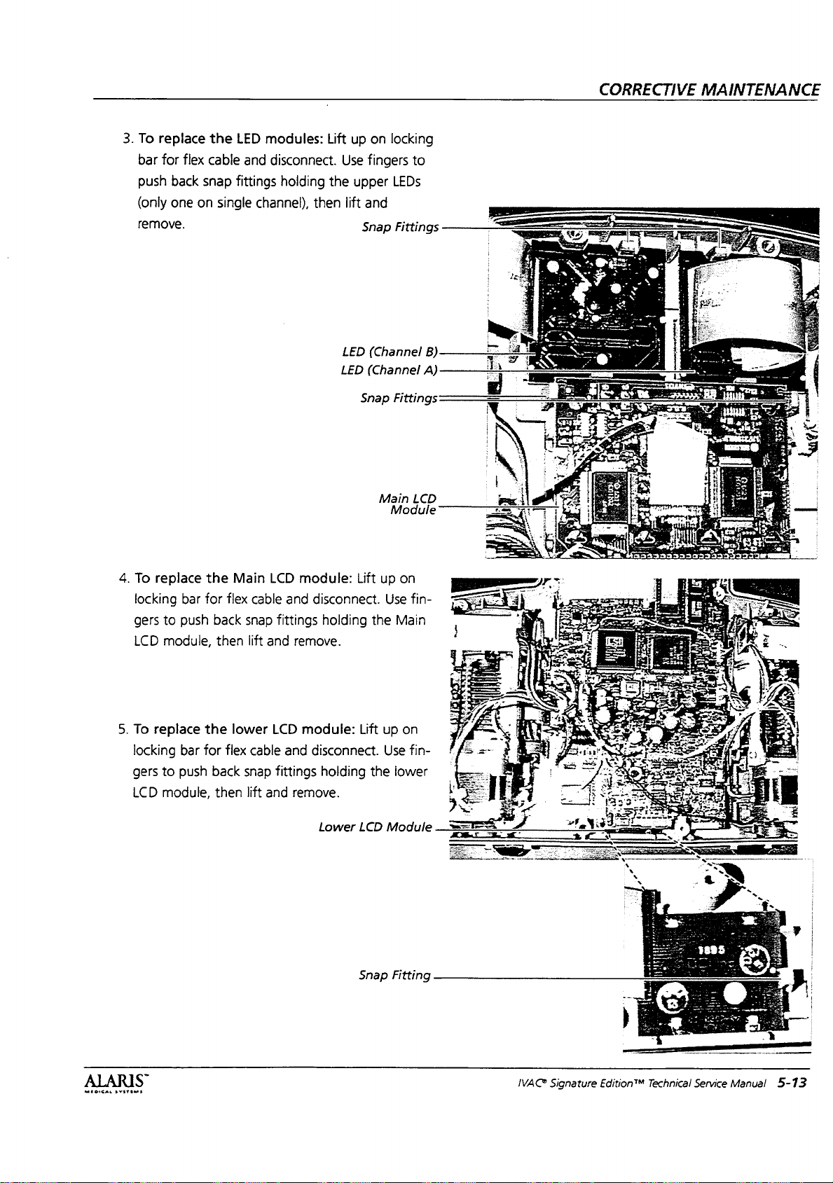
3.
To
bar
push
(only
remove.
replace
for
flex
back
snap
one
on
the
LED
cable
fittings
single
modules:
and
disconnect.
holding
channel),
Lift
the
then
up
Use
upper
lift
LED
LED
on
locking
fingers
LEDs
and
Snap
Fittings
(Channel
(Channel
Snap
Fittings
to
B)
A)
CORRECTIVE
MAINTENANCE
4.
To
locking
gers
LCD
5.
To
locking
gers
LCD
replace
bar
to
push
module,
replace
bar
to
push
module,
the
for
back
then
the
for
back
then
Main
flex
snap
lift
lower
flex
cable
snap
lift
LCD
cable
fittings
and
LCD
fittings
and
module:
and
disconnect.
holding
remove.
module:
and
disconnect.
holding
remove.
Lower
Main
Lift
the
Lift
the
LCD
Module
up on
Use
Main
up
on
Use
fin-
lower
Module
LCD
fin-
MEDICAL
SYSTEMS
”
Snap
Fitting
IVAC
Signature
Edition™
Technical
Service
Manual
5-13

CORRECTIVE
6.
To
replace
a.
First,
following
“Disassembling
NOTE:
Pay
bling
ensure
close
the
instrument.
they
are
b.
Move
This
case
c.
Disconnect
PCB.
nected
dure.
MAINTENANCE
the
mechanism:
separate
attention
not
mechanism
will
when
Note
to
the
the
procedure
The
pinched
allow
the
extracted.
wiring
their
the
same
Pump”.
to
location.
front
and
in
cable
cables
routing
are
or
stressed
latch
to
air-in-line
harnesses
They
location
rear
case
Section
specifically
when
the
sensor
from
later
5.4,
-when
disassem-
routed
reassembled.
middle
to
the
will
be
tn
the
halves
to
position.
clear
the
Main
recon-
proce-
d.
Using a flat
three
snap
the
mechanism
the
pumping
e.
Mark
the
“B”
with
tion
in
pumps.
CAUTION:
mechanisms
with
other
mechanism
go
back
the
pump
pressure
rate
calibration.
f.
Install
the
head
screw
fittings
to
mechanism.
mechanism(s)
permanent
the
proper
instruments.
is
in
the
will
calibration,
mechanism.
location
Do
in
dual
removed,
original
need
driver,
(top
and
the
front
latch
ink
to
not
channel
When
it
position
hard
and
as
well
unsnap
both
sides)
case,
then
housing
ensure
on
reinstalla-
dual
channel
mix Snap
or
a
must
or
soft
as
Snap
the
holding
remove
“A”
or
Fittings
.
Pumping
Mechanisms
Fittings=
5-14
g.
Perform
chapters 5 and
IVAC®
Signature
pressure
6).
Edition®M
and
rate
Technical
calibration
Service
(see
Manual
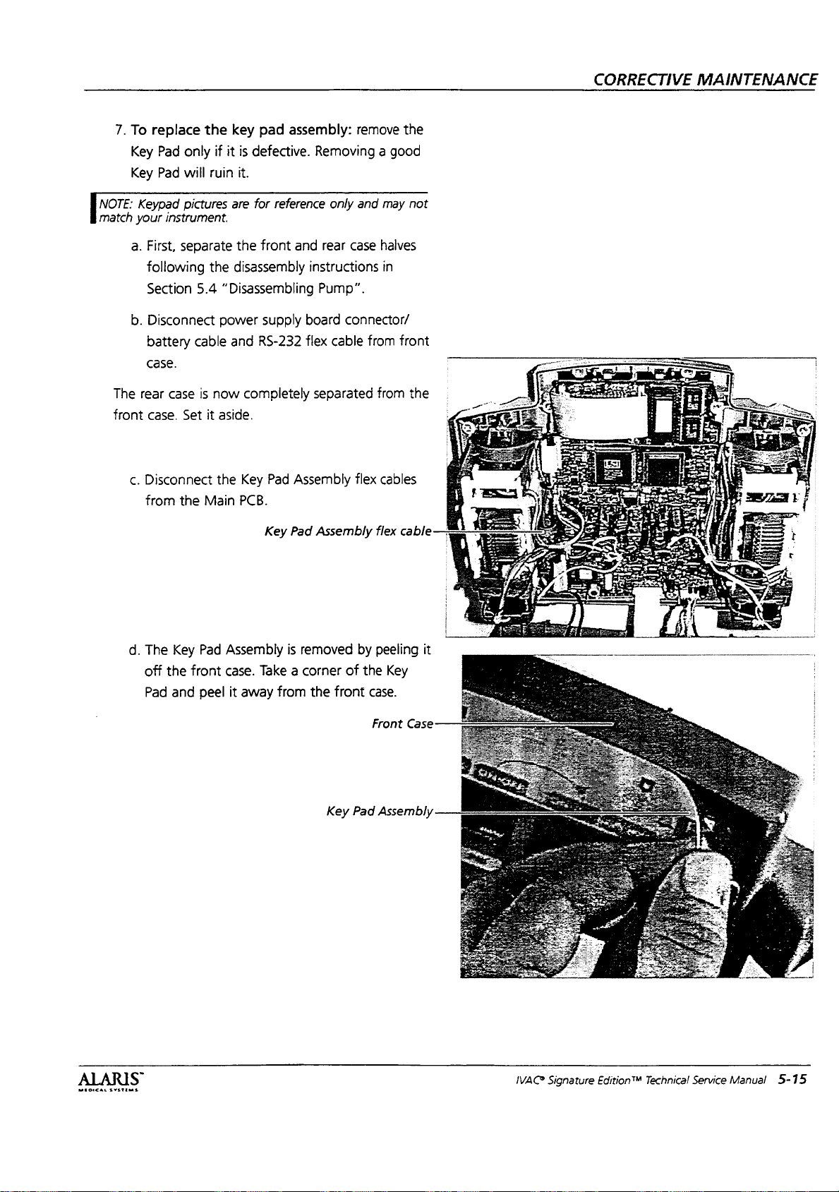
NOTE:
match
7.
To
Key
Key
Keypad
your
a.
First,
following
Section
b.
Disconnect
battery
case.
The
rear
front
case.
c.
Disconnect
from
replace
Pad
only
Pad
will
pictures
instrument.
separate
5.4
cable
case
is
Set
the
the
key
pad
if it
is
defective.
ruin
it.
are
for
reference
the
front
the
disassembly
“Disassembling
power
supply
and
RS-232
now
completely
it
aside.
the
Key
Pad
Main
PCB.
assembly:
remove
Removing a good
only
and
and
rear
case
instructions
Pump”.
board
connector/
flex
cable
separated
Assembly
flex
may
halves
in
from
from
cables
the
not
front
the
CORRECTIVE
MAINTENANCE
d.
The
off
Pad
Key
the
and
Pad
front
peel
Key
Assembly
case.
Take a corner
it
away
from
Pad
Assembly
is
removed
the
of
front
Key
by
the
case.
Front
Pad
flex
cable
peeling
Key
Case
Assembly
it
MEDICAL
Systems
S
IVAC®
Signature
Edition®M
Technical
Service
Manual
5-15
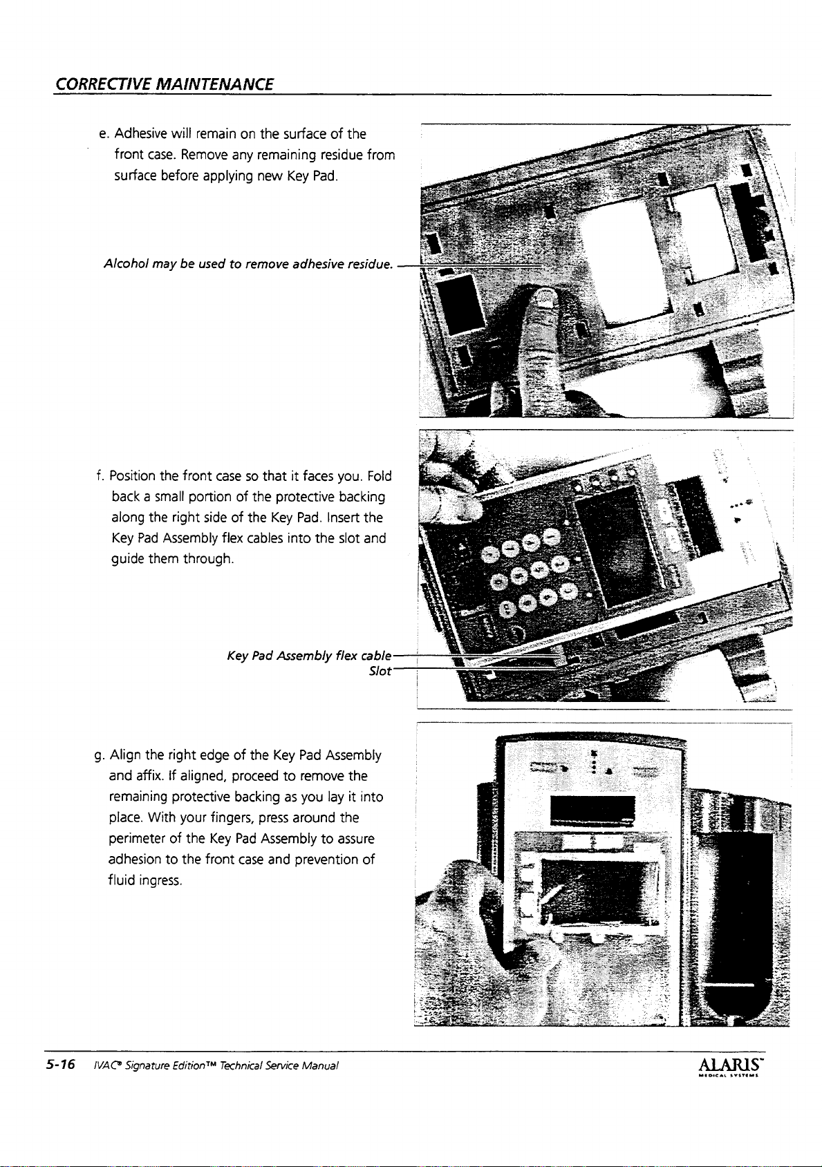
CORRECTIVE
MAINTENANCE
e.
Adhesive
front
case.
surface
Alcohol
f.
Position
back a small
along
the
Key
Pad
guide
them
will
Remove
before
may
be
the
front
portion
right
Assembly
through.
remain
on
any
applying
used
to
case
of
side
of
flex
the
surface
remaining
new
Key
remove
so
that
the
protective
the
Key
cables
into
of
residue
Pad.
adhesive
it
faces
Pad.
Insert
the
the
from
residue.
you.
Fold
backing
the
slot
and
5-16
g.
Align
and
remaining
place.
perimeter
adhesion
fluid
WACS
Signature
the
right
affix.
If
aligned,
protective
With
your
of
to
the
ingress.
Edition™
edge
fingers,
the
Key
front
of
the
proceed
backing
press
Pad
Assembly
case
and
Technical
Service
Key Pad
to
remove
as
you
around
prevention
Manual
Assembly
the
lay
it
into
the
to
assure
of
MEDICAL
SYSTEMS
”
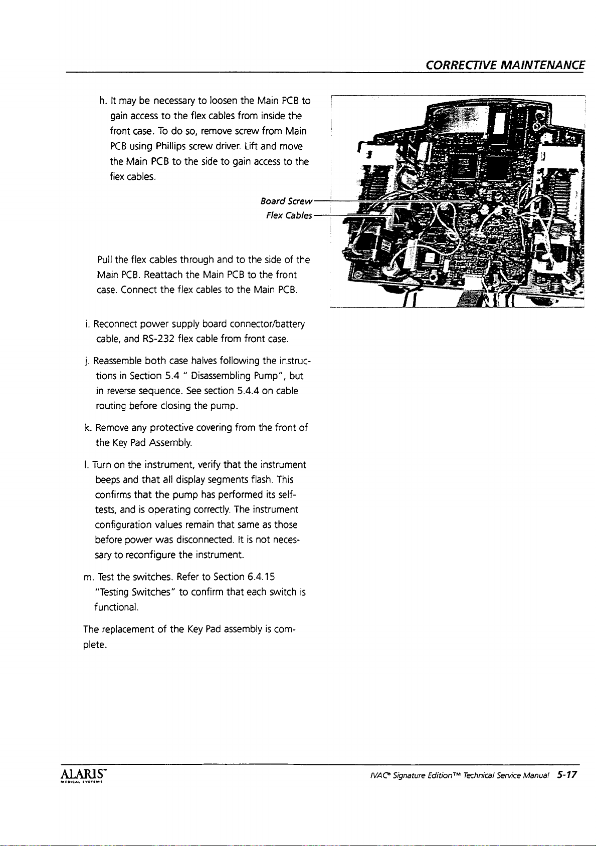
CORRECTIVE
MAINTENANCE
h.
It
may
gain
front
PCB
the
flex
Pull
the
Main
PCB.
case.
Connect
i.
Reconnect
cable,
j.
Reassemble
tions
in
in
reverse
routing
be
access
case.
using
Main
PCB
cables.
flex
cables
Reattach
power
and
RS-232
both
Section
sequence.
before
necessary
to
To
Phillips
the
the
flex
do
so,
screw
to
the
through
the
flex
supply
flex
case
halves
to
loosen
cables
remove
driver.
side
and
Main
cables
board
cable
following
to
PCB
to
connector/battery
from
5.4 “ Disassembling
See
section
closing
the
pump.
the
from
screw
Lift
gain
to
the
to
the
front
5.4.4
Main
inside
from
and
move
access
Board
Flex
side
the
front
Main
PCB.
case.
the
instruc-
Pump”,
on
cable
PCB
the
Main
to
the
Screw
Cables
of
the
but
to
|
k.
Remove
the
|.
Turn
beeps
any
Key
Pad
on the
and
confirms
tests,
and
configuration
before
sary
m.
“Testing
functional.
The
plete.
power
to
reconfigure
Test
the
switches.
Switches”
replacement
protective
Assembly.
instrument,
that
all
that
the
pump
is
operating
values
was
of
the
covering
verify
display
has
correctly.
remain
from
that
segments
performed
The
that
same
disconnected.
the
instrument.
Refer
to
Section
to
confirm
Key
Pad
assembly
that
the
the
instrument
flash.
its
instrument
as
It
is
not
6.4.15
each
is
front
This
self-
those
neces-
switch
com-
of
is
MEDICAL
SYSTEMS
S
IVAC
Signature
Edition™
Technical
Service
Manual
5-17

CORRECTIVE
5.4.4
Reassembly
NOTE:
Cable
are
not
maintained.
ing
pinched
was
1.
When
different,
Ensure
installed
cable
clamps,
transducer.
MAINTENANCE
Procedure
routing
and
Main
in
may
ease
the
pump
follow
PCB
pump.
if
present,
change
that
Board
Route
of
assembly
was
cable
and
for
over
time
opened,
routing
mechanism
ground
and
connect
Cable
to
ensure
and
disassembly
if
the
scheme.
wires
to
Routing
wires
cable
rout-
are
through
the
is
.
Route
under
left
side
out
right
gle).
Bend
frame.
.
Route
(white)
with
motor
board
.
Route
side
of
ail
transmitter
the
right
both
to
3
around
B
ail
transmitter
CH A ail
loop
as
transducer
motor
for
side
wire
Connect
channel A air-in-line
up
over
cable
(blue)
assembly
CH A (dual)
for
up
motor
wires
out
and
CH B (sin-
and
lay
to
the
main
and
for
CH
along
transmitter
install
A.
assembly.
CH A ail
mechanism.
main
.
receiver
cable
of
mechanism.
board.
both
cables.
cable
.
receiver
cable
cable
Route
CH B .
(white)
Connect
Install
tie # AL
Ensure
(white)
(black)
shown.
AIL
mechanism
board.
tie
Connect
(black)
to
CH
and
has
Transducer
(Channel
(Channel
Transmitter
Tie
wire
wrap
#5
to
main
out
to
me
wrap
me,
Receiver
(Channel
Cable
wire
wrap
left
Loop
#3
Cable
B)
A)
—
#5
A)
n
AL:
5-18
.
Route
side
and
to
main
.
Route
left
under
Connect
.
Connect
assembly
board.
.
Install
motor,
ail
transmitter
wires.
IVAC
Signature
CH A rotation
over
back
4-bar
board.
CH A latch
back
to
CH A motor
cable
tie
#4
latch,
4-bar.
main
board.
to
around
rotation
(white)
Edition™
sensor
main
sensor
(mechanism).
to
.
CH
A
and
Technical
cable
out
Rotation
Motor
AIL
Transmitter
Service
to
right
Connect
Back 4 Bar
Latch
(Channel
Tie
wrap
sensor
(Channel
Assembly
Manual
sensor
A)
#4
cable
A)
cable
cable
MEDICAL
SYSTEMS
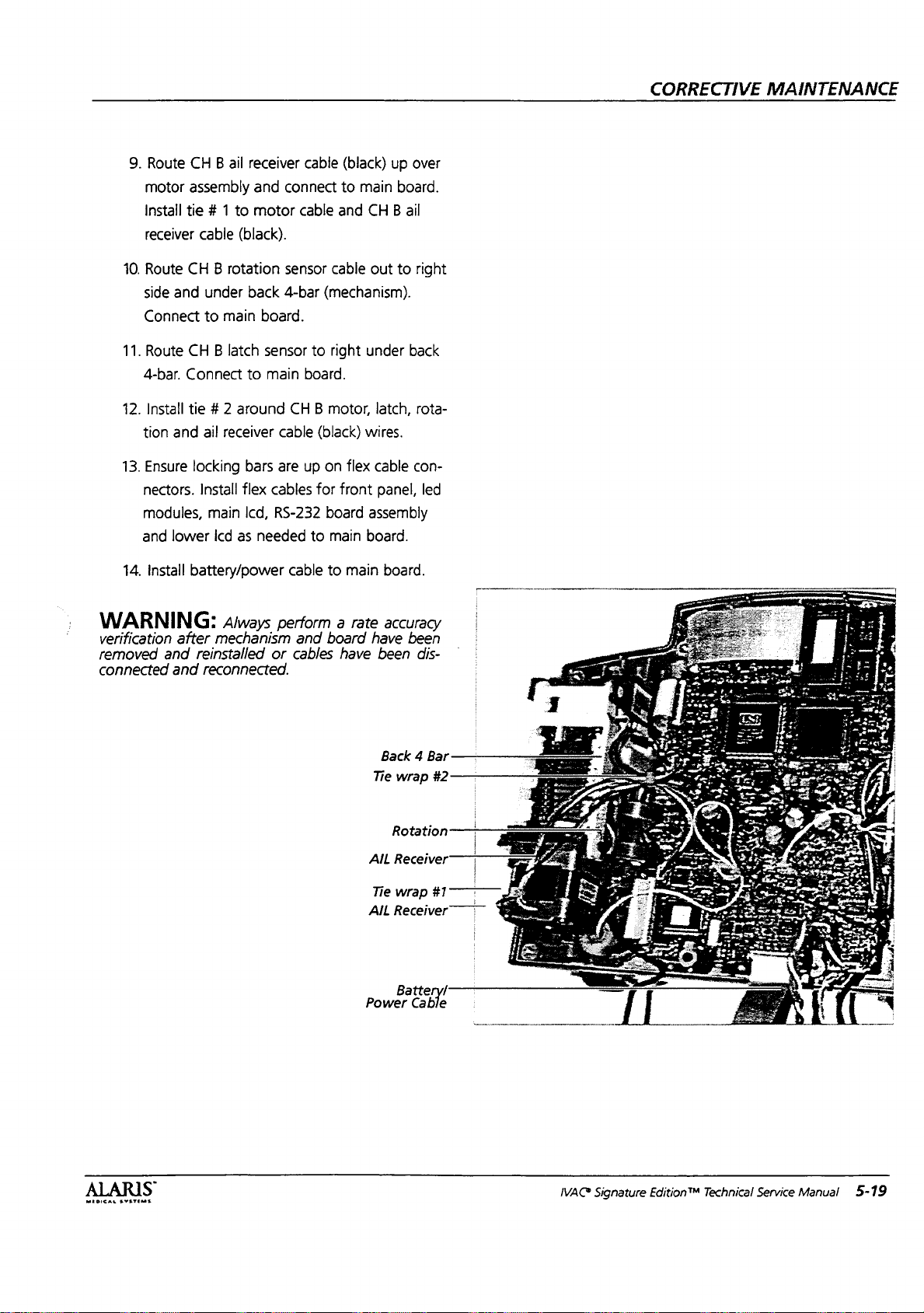
9.
Route
motor
Install
receiver
10.
Route
side
Connect
11.
Route
4-bar.
12.
Install
tion
13.
Ensure
nectors.
modules,
and
CH
B ail
receiver
assembly
tie # 1
cable
CH B rotation
and
under
to
CH B latch
Connect
tie # 2
and
ail
locking
Install
lower
to
(black).
main
around
receiver
flex
main
icd
as
and
motor
back
to
bars
lcd,
needed
cable
connect
cable
sensor
4-bar
board.
sensor
main
board.
CH B motor,
cable
are
up
cables
RS-232
(black)
to
main
and
CH B ail
cable
out
(mechanism).
to
right
under
latch,
(black)
for
to
on
flex
front
board
main
wires.
cable
panel,
assembly
board.
up
over
board.
to
right
back
rota-
con-
led
CORRECTIVE
MAINTENANCE
14.
Install
WARNING:
verification
removed
connected
and
and
battery/oower
Always
after
mechanism
reinstalled
reconnected.
cable
to
main
perform a rate
and
board
or
cables
have
Power
board.
accuracy
have
been
been
dis-
Back 4 Bar
Tie
wrap
Rotation 一 一
Receiver
AIL
Tie
wrap
AIL
Receiver” ” m
Battery!
Cable
#2
TT"
11777
i
MEDICAL
SYSTEMS
IVA@
Signature
Edition™
Technical
Service
Manual
5-19
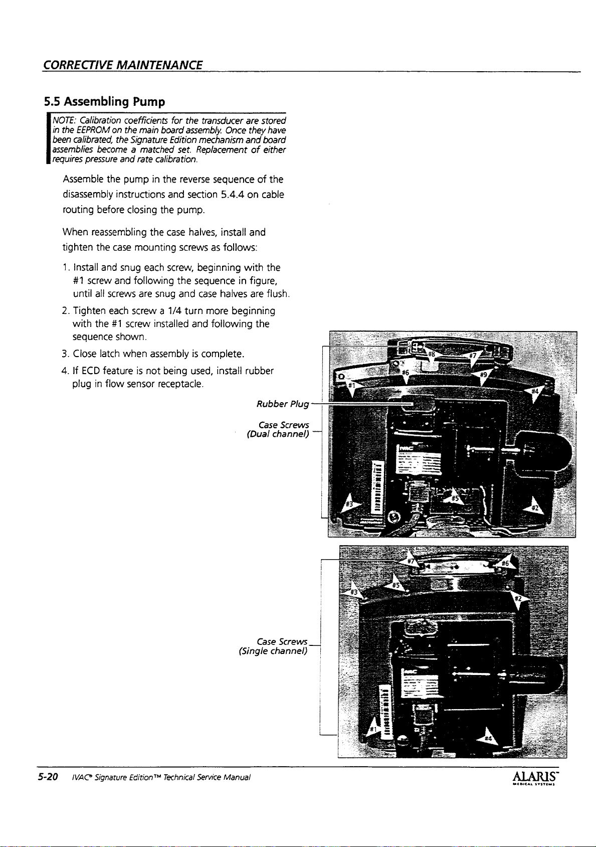
CORRECTIVE
5.5
Assembling
NOTE:
Calibration
in
the
EEPROM
been
calibrated,
assemblies
requires
become a matched
pressure
MAINTENANCE
Pump
coefficients
on
the
main
the
Signature
and
board
rate
calibration.
Edition
for
the
assembly.
set.
transducer
Once
mechanism
Replacement
are
they
and
of
stored
have
board
either
Assemble
disassembly
routing
When
tighten
1.
Install
#1
until
2.
Tighten
with
sequence
3.
Close
4.
If
plug
the
before
reassembling
the
and
screw
all
screws
each
the
#1
latch
ECD
feature
in
flow
pump
in
the
instructions
closing
case
snug
and
screw
shown.
when
sensor
the
the
case
mounting
each
screw,
following
are
snug
screw a 1/4
installed
assembly
is
not
being
receptacle.
reverse
and
section
pump.
screws
the
and
turn
sequence
5.4.4
haives,
used,
install
as
beginning
sequence
case
halves
more
and
following
is
complete.
install
of
on
and
follows:
with
in
figure,
are
beginning
the
rubber
Rubber
Case
(Dual
the
cable
the
flush.
Screws
channel)
Plug
"T
5-20
IVAC
Signature
Edition™
Technical
Service
(Single
Manual
Case
channel)
Screws
__|
MEDICAL
SYSTEMS
 Loading...