

Alaris SE Pump 7130, SE Pump 7131, SE Pump 7230, SE Pump 7231 Service manual
Directions for Use
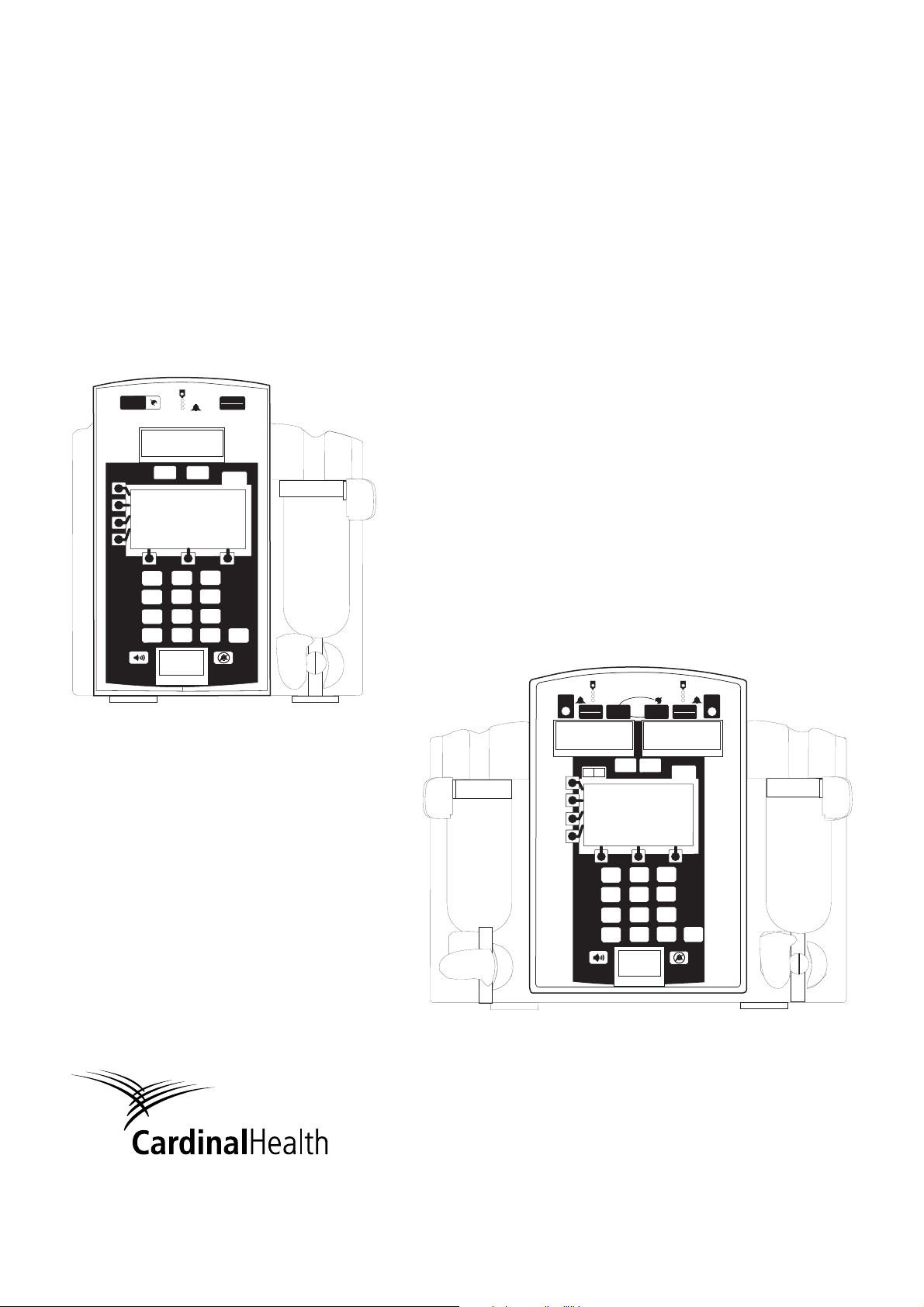
Alaris® SE Pump
Models 7130/7131 and 7230/7231
Supports Guardrails® Suite MX
June 2006
POWER
OPT PRI HLD SEC KVO
PRI
1
4
7
.
ml/hr
SEC
OPTIONS
23
56
9
8
Clear
0
RUN
HOLD
Enter
A
RUN
HOLD
A B
HLD PRI SECKVO OPT
POWER
ml/hr
PRI
POWER
PRI SEC HLD
SEC
RUN
HOLD
OPTION
ml/hr
OPT KVO
B
1
2
3
5
4
7
•
6
9
8
Clear
0
Enter
Alaris® Products

For service contact your local Affiliate Office or Distributor.
AE
Cardinal Health,
PO Box 5527,
Dubai, United Arab Emirates.
Tel: (971) 4 28 22 842
Fax: (971) 4 28 22 914
DE
Cardinal Health,
Pascalstr. 2,
52499 Baesweiler,
Deutschland.
Tel: (49) 2401 604 0
Fax: (49) 2401 604 121
IT
Cardinal Health,
Via Ticino 4,
50019 Sesto Fiorentino,
Firenze, Italia.
Tél: (39) 055 30 33 93 00
Fax: (39) 055 34 00 24
US
Cardinal Health
10221 Wateridge Circle,
San Diego, CA 92121,
USA.
Tel: (1) 800 854 7128
Fax: (1) 858 458 6179
AU
Cardinal Health,
8/167 Prospect Highway,
Seven Hills, NSW 2147,
Australia.
Tel: (61) 2 9838 0255
Fax: (61) 2 9674 4444
Fax: (61) 2 9624 9030
ES
Cardinal Health,
Avenida Valdeparra 27,
28108 - Alcobendas, Madrid,
España.
Tel: (34) 91 657 20 31
Fax: (34) 91 657 20 42
NL
Cardinal Health,
Kantorenpand “Hoefse Wing”,
Printerweg, 11,
3821 AP Amersfoort,
Nederland.
Tel: (31) 33 455 51 00
Fax: (31) 33 455 51 01
ZA
Cardinal Health,
Unit 2 Oude Molen Business
Park,
Oude Molen Road, Ndabeni,
Cape Town 7405, South Africa.
Tel: (27) (0) 860 597 572
Tel: (27) 21 510 7562
Fax: (27) 21 5107567
BE
Cardinal Health,
Otto De Mentockplein 19,
1853 Strombeek - Bever,
Belgium.
Tel: (32) 2 267 38 99
Fax: (32) 2 267 99 21
FR
Cardinal Health,
Immeuble Antares - Technoparc,
2, rue Charles-Edouard Jeanneret.
78300 POISSY,
France.
Tél: (33) 1 30 06 74 60
Fax: (33) 1 39 11 48 34
NO
Cardinal Health
Solbråveien 10 A,
1383 ASKER,
Norge.
Tel: (47) 66 98 76 00
Fax: (47) 66 98 76 01
CA
Cardinal Health,
235 Shields Court,
Markham,
Ontario L3R 8V2,
Canada.
Tel: (1) 905-752-3333
Fax: (1) 905-752-3343
GB
Cardinal Health,
The Crescent, Jays Close,
Basingstoke,
Hampshire, RG22 4BS,
United Kingdom.
Tel: (44) 0800 917 8776
Fax: (44) 1256 330860
NZ
Cardinal Health,
14 George Bourke Drive
Mt Wellington, Auckland
PO Box 14234
Panmure, Auckland
Tel: 09 270 2420
Freephone: 0508 422734
Fax: 09 270 6285
CN
Cardinal Health,
Shanghai Representative Office,
Suite 9B,
Century Ba-Shi Building,
398 Huai Hai Rd(M.),
Shanghai 200020,
China.
Tel: (56) 8621-63844603
Tel: (56) 8621-63844493
Fax: (56) 8621-6384-4025
HU
Cardinal Health,
Döbrentei tér 1,
H-1013 Budapest,
Magyarország.
Tel: (36) 14 88 0232
Tel: (36) 14 88 0233
Fax: (36) 12 01 5987
SE
Cardinal Health,
Hammarbacken 4B,
191 46 Sollentuna,
Sverige.
Tel: (46) 8 544 43 200
Fax: (46) 8 544 43 225
General Contact Information
©200 6 Cardinal Health, Inc. or one of its subsidiaries. All rights reserved.
Directions for Use
Alaris® SE Pump
Models 7130/7131, 7320/7231

Table of Contents
GETTING STARTED
INTRODUCTION ................................................................................................................................................................................................ 1
UNPACKING ......................................................................................................................................................................................................... 3
CHECK-IN AND CONFIGURATION .......................................................................................................................................................... 4
Rate Accuracy Qualification Test ...................................................................................................................................................... 4
Alternative Rate Accuracy Qualification Test .............................................................................................................................. 8
Set Sensor Check / Pressure Calibration Verification
Functional Test
Flow Stop Test ........................................................................................................................................................................................... 13
Ground Current Leakage Test ............................................................................................................................................................ 13
Ground Resistance Test ....................................................................................................................................................................... 13
Instrument Configuration ...................................................................................................................................................................... 13
ADMINISTRATION SET INFORMATION ................................................................................................................................................ 14
General ......................................................................................................................................................................................................... 14
SmartSite® Infusion Set ......................................................................................................................................................................... 14
Preparing Solution Container and Set ............................................................................................................................................ 15
Loading Set ................................................................................................................................................................................................ 16
Removing Set ............................................................................................................................................................................................ 18
Changing Solution Container .............................................................................................................................................................. 18
.......................................................................................................................................................................................... 11
PROGRAMMING
PROGRAMMING AND NAVIGATION TIPS ........................................................................................................................................... 19
Soft Keys ..................................................................................................................................................................................................... 19
Entering Values ......................................................................................................................................................................................... 19
Menus - With Guardrails® Suite MX Protection .......................................................................................................................... 20
Menus - NO Guardrails® Suite MX Protection ............................................................................................................................. 21
Split Screen (Dual Channel Only) ..................................................................................................................................................... 21
Powering On and Off .............................................................................................................................................................................. 21
Responding to Maintenance Reminder .......................................................................................................................................... 23
Responding to Time Set Reminder .................................................................................................................................................. 23
GUARDRAILS® SUITE MX PROMPTS .................................................................................................................................................... 24
Soft Limits ................................................................................................................................................................................................... 24
Hard Limits .................................................................................................................................................................................................. 24
PRIMARY INFUSION - WITH GUARDRAILS® SUITE MX PROTECTION .............................................................................. 25
Selecting New Patient and Profile Options ................................................................................................................................... 25
Primary Infusion Introduction ............................................................................................................................................................. 27
Continuous Infusion ................................................................................................................................................................................ 27
Pausing and Restarting Infusion ....................................................................................................................................................... 31
Making Changes During Continuous Infusion ............................................................................................................................. 31
Resuming Interrupted Infusion ........................................................................................................................................................... 32
KVO Mode .................................................................................................................................................................................................. 33
Resuming Operation from KVO Mode ............................................................................................................................................ 34
Clearing Volume Infused ...................................................................................................................................................................... 34
Bolus Dose ................................................................................................................................................................................................. 34
Delivering a Bolus Dose Prior to Beginning Continuous Infusion ...................................................................................... 35
Delivering a Bolus Dose During a Continuous Infusion .......................................................................................................... 36
Bolus Only ................................................................................................................................................................................................... 37
Stopping Bolus Dose
Repeating a Bolus Dose
Intermittent Infusion ................................................................................................................................................................................ 40
Making Changes During Intermittent Infusion ............................................................................................................................. 43
IV Fluid Infusion ........................................................................................................................................................................................ 44
.............................................................................................................................................................................. 39
....................................................................................................................................................................... 39
............................................................................................................. 11
Directions for Use
Alaris® SE Pump
Models 7130/7131, 7230/7231
Table of Contents
i

PROGRAMMING (Continued)
SECONDARY INFUSION - WITH GUARDRAILS® SUITE MX PROTECTION ...................................................................... 46
Introduction ................................................................................................................................................................................................. 46
Setup ............................................................................................................................................................................................................. 47
Secondary Intermittent Infusion ........................................................................................................................................................ 48
PRIMARY INFUSION - NO GUARDRAILS® SUITE MX PROTECTION ................................................................................... 52
Selecting New Patient Option-Profiles Feature Not Enabled (OFF) ................................................................................. 52
Basic Infusion ............................................................................................................................................................................................ 52
Promoting Basic Infusion to Guardrails® Suite MX Protection Infusion ........................................................................... 53
Promoting Basic Infusion to Guardrails® Drug Infusion .......................................................................................................... 53
Promoting Basic Infusion to Guardrails® IV Fluid Infusion ..................................................................................................... 55
Dose Rate Calculation- Drug? NO DOSE LIMIT-Profiles Feature Enabled (ON) ....................................................... 56
Dose Rate Calculation- Drug? NO DOSE LIMIT-Profiles Feature Not Enabled (OFF) ............................................ 58
LOADING DOSE ................................................................................................................................................................................................. 61
Programming ............................................................................................................................................................................................. 61
MULTI-DOSE ........................................................................................................................................................................................................ 63
Programming ............................................................................................................................................................................................. 63
Resuming an Interrupted Multi-Dose .............................................................................................................................................. 68
MULTI-STEP ......................................................................................................................................................................................................... 69
Programming ............................................................................................................................................................................................. 69
Making Changes During Multi-Step ................................................................................................................................................. 75
Resuming an Interrupted Multi-Step ............................................................................................................................................... 78
QUITTING MULTI-DOSE AND MULTI-STEP ....................................................................................................................................... 79
SECONDARY INFUSION - NO GUARDRAILS® SUITE MX PROTECTION ........................................................................... 80
Introduction ................................................................................................................................................................................................. 80
Basic Secondary Infusion-Profiles Feature Enabled (On) ..................................................................................................... 80
Basic Secondary Infusion-Profiles Feature Not Enabled (Off) ............................................................................................ 81
DYNAMIC MONITORING SYSTEM
MONITORING OPTIONS - GENERAL ..................................................................................................................................................... 83
Selecting Monitoring Option ................................................................................................................................................................ 84
MONITORING OPTIONS - RESISTANCE MODE .............................................................................................................................. 86
Detection of Downstream Occlusions ............................................................................................................................................. 86
Auto Restart Plus Feature .................................................................................................................................................................... 87
Resistance Alert ....................................................................................................................................................................................... 88
Resistance Trend Graphs .................................................................................................................................................................... 89
MONITORING OPTIONS - PRESSURE MODE .................................................................................................................................. 92
Detection of Downstream Occlusions ............................................................................................................................................. 92
Auto Restart Plus Feature .................................................................................................................................................................... 92
Adjustable Pressure Alarm .................................................................................................................................................................. 93
Pressure Baseline ................................................................................................................................................................................... 95
Pressure Trend Graphs ......................................................................................................................................................................... 97
UPSTREAM OCCLUSION DETECTION ................................................................................................................................................. 10 0
GENERAL SETUP AND OPERATION
AUDIO ADJUST .................................................................................................................................................................................................. 103
TAMPER RESIST ............................................................................................................................................................................................... 103
Locking and Unlocking Panel Lock .................................................................................................................................................. 103
ii
Table of Contents
Directions for Use
Alaris® SE Pump
Models 7130/7131, 7230/7231

GENERAL INFORMATION
WARNINGS AND CAUTIONS ...................................................................................................................................................................... 105
General ......................................................................................................................................................................................................... 105
Guardrails® Suite MX ............................................................................................................................................................................. 106
Administration Sets ................................................................................................................................................................................. 107
Epidural Administration ......................................................................................................................................................................... 107
Electromagnetic Compatibility ............................................................................................................................................................ 108
BATTERY MANAGEMENT SYSTEM ........................................................................................................................................................ 109
Battery Power Gauge and Indicator ................................................................................................................................................ 110
Battery Recharge ..................................................................................................................................................................................... 110
FLOW SENSOR .................................................................................................................................................................................................. 110
ALERTS COUNTER .......................................................................................................................................................................................... 112
Definitions ................................................................................................................................................................................................... 112
Viewing Alerts Counter ......................................................................................................................................................................... 113
NURSE CALL (7130/7230 ONLY) ............................................................................................................................................................... 114
Activating Nurse Call Feature ............................................................................................................................................................. 114
If an Alarm Occurs .................................................................................................................................................................................. 114
POLE CLAMP ...................................................................................................................................................................................................... 115
Changing Pole Clamp Orientation .................................................................................................................................................... 115
RS-232 COMPUTER LINK ............................................................................................................................................................................. 116
Connecting to a Computer .............................................................................................................................. ..................................... 116
Disconnecting from a Computer ....................................................................................................................................................... 117
FEATURES AND DISPLAYS ......................................................................................................................................................................... 118
Operating Features, Controls, Indicators ...................................................................................................................................... 118
Displays ........................................................................................................................................................................................................ 121
Feature Definitions .................................................................................................................................................................................. 122
CONFIGURABLE SETTINGS ...................................................................................................................................................................... 123
Configurable Option Definitions-General ...................................................................................................................................... 124
Configurable Option Definitions-Guardrails® Suite MX ........................................................................................................... 128
Configurable Options ............................................................................................................................................................................. 129
System Configurable Options ............................................................................................................................................................ 130
SPECIFICATIONS .............................................................................................................................................................................................. 130
SYMBOLS AND TERMS ................................................................................................................................................................................. 134
TRUMPET AND START-UP CURVES ..................................................................................................................................................... 137
Pressure Mode .......................................................................................................................................................................................... 138
Resistance Mode ..................................................................................................................................................................................... 140
High Resistance Mode .......................................................................................................................................................................... 142
TROUBLESHOOTING AND MAINTENANCE
GENERAL .............................................................................................................................................................................................................. 143
AIR IN LINE ASSEMBLY ................................................................................................................................................................................. 143
SINGLE OR ACCUMULATED AIR BUBBLE DETECTION (NO RESET FEATURE) .......................................................... 144
ALARMS, ALERTS, PROMPTS .................................................................................................................................................................. 145
Alarms ........................................................................................................................................................................................................... 146
Alerts ............................................................................................................................................................................................................. 15 0
Prompts ........................................................................................................................................................................................................ 151
INSPECTION REQUIREMENTS ................................................................................................................................................................. 156
CLEANING ............................................................................................................................................................................................................ 156
SERVICE INFORMATION .............................................................................................................................................................................. 158
Technical Support .................................................................................................................................................................................... 158
WARR ANTY ......................................................................................................................................................................................................... 159
Directions for Use
Table of Contents
Alaris® SE Pump
Models 7130/7131, 7230/7231
iii

REGULATIONS AND STANDARDS
COMPLIANCE ..................................................................................................................................................................................................... 161
Electromagnetic Environment ............................................................................................................................................................ 161
Standards .................................................................................................................................................................................................... 168
TRADEMARKS .................................................................................................................................................................................................... 168
DIRECTIONS FOR USE SUPPLEMENTS
SUPPLEMENTS................................................................................................................................................
169
iv
Table of Contents
Directions for Use
Alaris® SE Pump
Models 7130/7131, 7230/7231

Introduction
Getting Started
This document provides directions for use for the SE Pump,
Models 7130/7131 and 7230/7231. It is used in conjunction
with:
®
Alaris
product administration set instructions
Drug product labeling
SE Pump Technical Service Manual
Ground test equipment instructions
ECG monitoring system instructions
The SE Pump is intended for use in professional healthcare
environments, including healthcare facilities, home care, and
medical transport, that utilize infusion pumps for the delivery of
fluids, medications, blood, and blood products. It is indicated
for continuous or intermittent delivery through clinically
acceptable routes of administration; such as, intravenous
(IV), intra-arterial (IA), subcutaneous, epidural, enteral, and
irrigation of fluid spaces.
The SE Pump is available as either a single or a dual channel
pump that supports the Guardrails
®
Suite MX. The SE Dual
Channel Pump is a two-channel device intended to deliver
multiple infusions to a single patient.
Guardrails
®
Suite MX for the SE Pump brings a new level
of medication error prevention to the point of patient care.
Guardrails
®
Suite MX features programming guidelines for
medication dosing, delivery rate, duration, bolus dose and
bolus dose administration rate, concentration and optional
initial programming values in up to 15 patient-specific care
areas referred to as profiles. Each profile contains a specific
Drug Library and an IV Fluid library as well as instrument
configurations appropriate for the care area. Optional drugspecific or fluid-specific clinical advisories provide visual
messages. Limits for each Guardrails
®
drug or fluid entry may
include Hard Limits that cannot be overridden during infusion
programming and/or Soft Limits that can be overridden, based
on clinical requirements.
WARNING
Read all instructions before using
the SE Pump.
CAUTION
A Data Set is developed and approved by the facility’s own
multi-disciplinary team using the Editor Software, the PCbased authoring tool. A Data Set is then transferred to the
SE Pump by qualified personnel. Approved Data Sets are
maintained by the Editor Software for future updates and
reference.
Directions for Use
Alaris® SE Pump
Models 7130/7131, 7230/7231
Getting Started
1

Introduction (Continued)
Information about a Guardrails® alert that occurs during use
is stored within the SE Pump, and can be accessed using the
CQI Reporter.
The SE Pump may be operated with or without the Guardrails
Suite MX protection. When an approved Data Set is
transferred to the SE Pump by qualified personnel and the
Profiles feature is enabled (ON) in instrument configuration,
then Guardrails
®
Suite MX protection is available. When
the Profiles feature is not enabled (Off), or when no Data
Set has been transferred to the SE Pump, Guardrails
®
Suite
MX protection is not available (see "Primary Infusion – NO
Guardrails
- NO Guardrails
navigation may differ when Guardrails
®
Suite MX Protection", and "Secondary Infusion
®
Suite MX Protection"). Programming and
®
Suite MX software is
not in use.
Documentation provided with this product may reference
product not present in your facility or not yet available for sale
in your area.
A superscript number (for example, À) identifies additional
information provided as a note at the end of the section.
Administration Sets: Reference “General Information” for
specific “Administration Set Information”.
Alarms, Alerts, Prompts: Reference “Troubleshooting and
Maintenance” for specific alarms, alerts and prompts.
®
Electromagnetic Environment: Reference “Regulations and
Standards”, "Compliance”.
Contraindications: None known.
Warnings and Cautions:
Warnings and cautions provide information needed to safely and
effectively use the SE Pump. Reference "General Information",
"Warnings and Cautions".
A
DANGER
is an alert to an imminent hazard which
could result in serious personal injury and/or product damage
if proper procedures are not followed.
WARNING
A
is an alert to a potential hazard which could
result in serious personal injury and/or product damage if
proper procedures are not followed.
2
Getting Started
Directions for Use
Alaris® SE Pump
Models 7130/7131, 7230/7231

Introduction (Continued)
Warnings and Cautions: (Continued)
A
CAUTION
is an alert to a potential hazard which could
result in minor personal injury and/or product damage if proper
procedures are not followed.
DEFINED TERMS:
The following table identifies the defined terms used
throughout this document for certain products and product
features.
Product Name Defined Term
AccuSlide® flow regulator Flow Regulator
Alaris® SE pump SE Pump
Guardrails
Guardrails® CQI Reporter CQI Reporter
Guardrails® data set Data Set
Guardrails® drug library Drug Library
Guardrails® Editor Editor Software
Guardrails® hard limit Hard Limit
Guardrails® IV fluid IV Fluid
Guardrails® soft limit Soft Limit
SmartSite® needle-free valve Needle-Free Valve
SmartSite® positive bolus needle-free valve Needle-Free Valve
®
clinical advisory Clinical Advisory
Unpacking
1. Remove instrument from carton.
2. Important: Plug instrument into an AC outlet a minimum
of 24 hours prior to use.
Maximum battery capacity, as well as gauge accuracy, is
reached after several charge/discharge/recharge cycles,
in the refresh process. Cardinal Health recommends that
the battery be fully charged/discharged/recharged, using
the refresh cycle, before placing the instrument in use.
3. Perform Periodic Inspections (reference "Troubleshooting
and Maintenance", “Inspection Requirements”).
See "General Information", "Configurable Settings" for a list of
the configurable features.
Directions for Use
Alaris® SE Pump
Models 7130/7131, 7230/7231
AC
WARNING
Failure to properly charge the
battery results in an instrument
malfunction. Biomedical personnel
in the facility are responsible for
unpacking the instrument and
ensuring the battery is fully charged
before placing the instrument in use.
Getting Started
3

Check-In and Configuration
This is a quick reference procedure for check-in and
configuration of new and recently serviced instruments.
Rate Accuracy Qualification Test
This procedure is to be used only for the testing of an
instrument during New Instrument Check-In or when just
received from the Service Depot Center. This test is to verify
that damage or changes to the instrument did not occur during
shipment and handling.
WARNING
Instruments returned from the
service depot may be set to
factory defaults and not have a
hospital-defined Data Set loaded.
Biomedical personnel in the facility
are responsible for checking-in the
instrument and ensuring the current
hospital-approved Data Set is
loaded.
CAUTION
Charge the battery for a minimum
of 24 hours prior to performing
the check-in and configuration
procedures. Batteries without
a full charge on initial use may
become damaged and/or cause a
malfunction.
Rate accuracy should be tested using a Model 80VCS
Calibration Set. The system is designed to produce overall
accuracy of ±5% for rates greater than 1 mL/h and up to
999.9 mL/h, and ±6.5% for rates equal to or less than 1 mL/h,
95% of the time with 95% confidence (reference "General
Information", "Trumpet and Start-Up Curves" for additional
information). The system performance with a calibration
set produces a smaller variability. In order to ensure overall
accuracy is achieved, new instruments are tested to an
accuracy of ±3% with the Model 80VCS set during New
Instrument Check-In.
Due to the dynamic monitoring feature, the rate is varied during
operation. For this reason, automatic testers should not be
used to check rate accuracy. Generally, these devices collect
small samples and may cause the results to be incorrect, even
though the instrument is accurate.
4
Getting Started
Directions for Use
Alaris® SE Pump
Models 7130/7131, 7230/7231
Check-In and Configuration (Continued)
Rate Accuracy Qualification Test (Continued)
Do not use the Model 80VCS Calibration Set for more than
30 rate verification runs (15 rate calibration number changes).
Keep track of the number of times the set is used by recording
each use on the 80VCS insert or on a separate record.
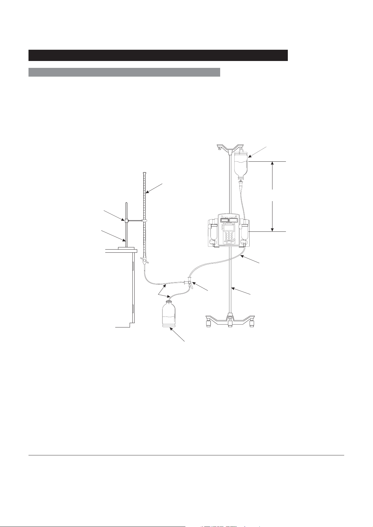
Test Setup
Burette (50 ml)
Burette Clamp
Equipment Stand
ableor Bench
Water Source
30 ±1 in
76.2 cm±2.5
Table or Bench
IV Tubing
Three-Way
Stopcock
Used Fluid Receptacle
1. Fill solution container with clean tap water. Close Flow
Regulator clamp on 80VCS set and then insert spike into
solution container.
2. Open Flow Regulator clamp and prime set. Ensure all air
is expelled from set. Close Flow Regulator clamp.
3. Connect output of set to one side of three-way stopcock.
4. Load set into instrument.
80VCS Calibration Set
Instrument Stand
Directions for Use
Alaris® SE Pump
Models 7130/7131, 7230/7231
Getting Started
5

Check-In and Configuration (Continued)
Rate Accuracy Qualification Test (Continued)
5. Close latch.
6. Verify no fluid flow or drops falling in drip chamber.
7. Plug instrument into a properly grounded AC outlet.
8. Set stopcock to output into a class A or B burette.
9. Press POWER key to turn channel on.
10. Set primary infusion rate to 400 mL/h.
11. Set VTBI to 20 mL.
12. Ensure instrument (both channels if dual channel) is set to
Pressure mode.
À
13. Press RUN/HOLD key to start primary infusion. Infuse
until tubing and burette are fully primed (approximately 1
minute).
14. Press RUN/HOLD key to stop infusion.
15. Adjust height of instrument and/or fluid container to attain
a head height of 30 ±1 inches / 76.2 ±2.5 centimeters
between middle of pumping mechanism and fluid level in:
Á
• bag or vented bottle (vent closed on administration set)
OR
• drip chamber (unvented bottle with vent open on
administration set).
16. Adjust fluid level in burette until meniscus is level with zero
mark on burette.
Â
17. Verify primary infusion rate is 400 mL/h.
18. Reset VTBI to 40 mL and clear volume infused.
19. Press RUN/HOLD key to start primary infusion.
20. Instrument will run approximately 360 seconds (6 minutes)
to complete delivery and then go into KVO mode. Stop
instrument within 1 second of its entering KVO mode.
21. Make a note of volume collected in burette.
22. Note expected volume, as identified on 80VCS set insert.
23. Do not remove 80VCS set from instrument until one of
following conclusions is determined:
6
Getting Started
Directions for Use
Alaris® SE Pump
Models 7130/7131, 7230/7231

Check-In and Configuration (Continued)
Rate Accuracy Qualification Test (Continued)
• Instrument passes rate verification and calibration is
not needed.
• Rate calibration number was changed and instrument
now passes verification.
• Mechanism replacement is required.
24. Calculate volume accuracy, as follows:
Volumetric Volume Accuracy Error Computation
Vcollected = volume in burette in milliliters
Vexpected = characterized volume printed on 80VCS set
insert
Step 1: A = Vcollected ÷ Vexpected
Step 2: B = A x 100
Step 3: % Error (round % Error to nearest tenth of a percent)
= B – 100
25. Result should be 0.0±3%.
26. If volume accuracy does not fall within required range of
±3% from expected volume and test results were:
• inside a range of -5.5% to +7.0% from expected
volume,
perform rate calibration (reference Technical Service
Manual). Set rate calibration number to 0.0% before
running rate test, to determine a new calibration
number.
• outside a range of -5.5% to +7.0% from expected
volume,
return instrument to Cardinal Health for repair or
replace mechanism.
27. Set stopcock to drain fluid in burette to zero level, in
preparation for next test.
NOTES:
À The factory default for the Monitoring Options mode is
Pressure.
Á A 30-inch head height was used in the initial qualification of
this process and is the recommended head height for the
Check-In Rate Accuracy Test. Based on observed field use, a
24-inch head height was also tested and verified for the Rate
Accuracy Specification.
 The instrument may need to be run to prime the line to the
zero level of the burette (step 13).
Directions for Use
Alaris® SE Pump
Models 7130/7131, 7230/7231
Getting Started
7

Check-In and Configuration (Continued)
Alternative Rate Accuracy Qualification Test
This procedure is to be used only for the testing of an
instrument during New Instrument Check-In or when just
received from the Service Depot Center. This test is to verify
that damage or changes to the instrument did not occur during
shipment and handling.
Make the following changes to Test Setup:
• Burette and equipment stand have been replaced by digital
scale, Acculab Vic-212 or equivalent and 50 or 100 mL
flask (plastic or glass).
• Three-way stopcock and used fluid receptacle are no
longer needed.
Due to the dynamic monitoring feature, the rate is varied
during operation. For this reason, Cardinal Health does not
recommend using automatic testers to check rate accuracy.
Generally, these devices collect small samples and may cause
the results to be incorrect, even though the instrument is
accurate.
Do not use the Model 80VCS set for more than 30 rate
verification runs (15 rate calibration number changes). Keep
track of the number of times the set is used by recording each
use on the 80VCS insert or on a separate record.
1. Fill solution container with clean tap water. Close Flow
Regulator clamp on 80VCS Calibration Set and then insert
spike into solution container.
2. Open Flow Regulator clamp and prime set. Ensure all air
is expelled from set. Close Flow Regulator clamp.
3. Place flask in middle of scale.
4. Load set into instrument.
5. Close latch.
6. Verify no fluid flow or drops falling in drip chamber.
7. Plug instrument into a properly grounded AC outlet.
8. Place output of set so it drips into flask. (Do not let set rest
on flask.)
9. Press channel’s POWER switch to turn channel on.
10. Set primary infusion rate to 400 mL/h.
8
Getting Started
Directions for Use
Alaris® SE Pump
Models 7130/7131, 7230/7231

Check-In and Configuration (Continued)
Alternative Rate Accuracy Qualification Test (Continued)
11. Set VTBI to 20 mL.
12. Ensure instrument (both channels if dual channel) is set to
Pressure mode.
À
13. Press RUN/HOLD key to start primary infusion. Infuse
until tubing is fully primed (approximately 1 minute).
14. Press RUN/HOLD key to stop infusion.
15. Adjust height of instrument and/or fluid container to attain
a head height of 30 ±1 inches between middle of pumping
mechanism and fluid level in:
• bag or vented bottle (vent closed on administration set)
OR
• drip chamber (unvented bottle with vent open on
administration set).
16. Zero reading on scale.
17. Verify primary infusion rate is 400 mL/h.
18. Reset VTBI to 40 mL and clear volume infused.
19. Press RUN/HOLD key to start primary infusion.
20. Instrument will run approximately 360 seconds (6 minutes)
to complete delivery and then go into KVO mode. Stop
instrument within 1 second of entering KVO mode.
21. Make a note of scale reading in grams.
22. Note expected volume, as identified on 80VCS set insert.
23. Do not remove 80VCS set from instrument until one of
following conclusions is determined:
• Instrument passes rate verification and calibration is
not needed.
• Rate calibration number was changed and instrument
now passes verification.
• Mechanism replacement is required.
Directions for Use
Alaris® SE Pump
Models 7130/7131, 7230/7231
Getting Started
9

Check-In and Configuration (Continued)
Alternative Rate Accuracy Qualification Test (Continued)
24. Calculate gravimetric accuracy as follows:
Gravimetric Volume Accuracy Error Computation
Vcollected = volume in flask in grams
Vexpected = characterized volume printed on 80VCS set
insert
Step 1: A = Vcollected / Vexpected
Step 2: B = A x 100
Step 3: % Error (Round % Error to nearest tenth of a
percent.) = B – 100
25. Result should be 0.0 ±3%.
26. If volume accuracy does not fall within required range of
±3.0% from expected volume and test results were:
• inside a range of -5.5% to +7.0% from expected
volume,
perform rate calibration (reference Technical Service
Manual). Set rate calibration number to 0.0% before
running rate test, to determine a new calibration
number.
• outside a range of -5.5% to +7.0% from expected
volume,
return instrument to Cardinal Health for repair or
replace mechanism.
27. Empty flask and reset scale to zero, in preparation for next
test.
NOTE:
À The factory default for the Monitoring Options mode is
Pressure.
10
Getting Started
Directions for Use
Alaris® SE Pump
Models 7130/7131, 7230/7231

Check-In and Configuration (Continued)
Set Sensor Check / Pressure Calibration Verification
1. Access DIAGNOSTICS MODE by pressing and holding
upper left soft key on power-up. Reference Technical
Service Manual, “Troubleshooting” chapter, for details or
contact Cardinal Health Technical Support.
À
2. Advance to D6 page and choose Cal Pressure (both
Channel A and Channel B for dual channel instruments).
3. Verify both 0 mmHg and 500 mmHg readings indicate
Pass.
4. Install a standard set and close latch. Verify reading is
over 170, to confirm set sensor operation.
5. Remove standard set and verify Sensor = reading is in
-80 to +30 mmHg range without set installed, to verify
pressure calibration.
NOTES:
À “08.XX” in the illustrated display represents the current
software revision.
Á If the reading is out of range, reference the Technical Service
Manual, “Pressure Calibration” section, or contact Cardinal
Health Technical Support for assistance.
Á
AB
DIAGNOSTICS MODE
ID No. : 000000000
SW Rev.: 08.XX
PM Due : 52 weeks
page
OPTIONS
D
1
Functional Test
1. Turn instrument on without set installed. Verify it beeps
and red alarm light flashes but does not stay lit.
2. Set infusion rate to 460 mL/h and VTBI to 100 mL.
3. With latch closed, press RUN/HOLD key and rate and
VTBI ≠ 0 to cause Set Out and Air In Line messages.
4. Open latch.
5. Install primed administration set with latch open.
6. Verify instrument displays Air In Line and Latch Open
messages.
7. Close latch and verify display returns to setup page.
Directions for Use
Alaris® SE Pump
Models 7130/7131, 7230/7231
Getting Started
11

Check-In and Configuration (Continued)
Functional Test (Continued)
8. Perform Upstream Occlusion Test, as follows:
a. Verify infusion rate is set to 460 mL/h.
b. With instrument on hold, or at start-up, verify primary
VTBI is set to greater than 100 mL.
c. Press RUN/HOLD key to begin infusion.
d. Clamp off IV line just above instrument (about
2 inches) to simulate an upstream occlusion.
e. Verify instrument stops running, alarms, and displays
OCCLUSION UPSTREAM within 60 seconds.
f. Press RUN/HOLD key to silence alarm and put
instrument on hold.
g. Release or open clamp and remove from tubing.
h. Press RUN/HOLD key to resume infusion. Alarm
should not reoccur.
9. Perform Downstream Occlusion Test, as follows:
a. Continue infusing (from step 8h).
b. Verify rate is set to 460 mL/h.
c. Clamp off IV line just below instrument (about
2 inches) to simulate a downstream occlusion.
d. Allow instrument to run until it alarms OCCLUSION
DOWNSTREAM. Verify this occurs within 60
seconds.
e. Press RUN/HOLD key to silence alarm and put
instrument on hold.
f. Release or open clamp and remove from tubing.
g. Press RUN/HOLD key to resume infusion. Alarm
should not reoccur.
h. Press RUN/HOLD key to stop infusion.
12
Getting Started
Directions for Use
Alaris® SE Pump
Models 7130/7131, 7230/7231

Check-In and Configuration (Continued)
Flow Stop Test
1. With an administration set primed and loaded in
instrument, turn power off.
2. With all tubing clamps open and fluid container 2 or more
feet above instrument, verify no fluid flows through set.
3. Open latch and remove set. Verify no fluid flows through
set.
Ground Current Leakage Test
Use a DNI Nevada Model 232D (or equivalent) to measure
the ground leakage current. Refer to the test equipment’s
operation manual for the proper setup and measurement
technique. Leakage current must be ≤100μA for normal and
reversed line polarity.
Ground Resistance Test
Use a DNI Nevada Model 232D (or equivalent) to measure the
ground resistance. Measure resistance from the AC power
plug ground pin to the screw for the power cord strap, or to
the screw for the battery cover on the chassis. Refer to the
test equipment’s operation manual for the proper setup and
measurement technique. Resistance must be ≤0.10Ω.
Instrument Configuration
Instrument Configuration for the SE Pump with the Guardrails®
Suite MX is set for each profile using the Editor Software, the
PC-based authoring tool. The Data Set is then transferred to
the SE Pump by qualified personnel.
The SE Pump may be operated with or without the Guardrails
Suite MX protection. When an approved Data Set is
transferred to the SE Pump by qualified personnel and the
Profiles feature is enabled (ON) in instrument configuration,
then Guardrails
®
Suite MX protection is available.
Instrument configuration is set by qualified personnel in the
Data Set or Configuration and Diagnostics modes. When
the Profiles feature is not enabled (Off), or when no Data
Set has been transferred to the SE Pump, Guardrails
®
Suite
MX protection is not available (see "Primary Infusion – NO
®
Guardrails
- NO Guardrails
Suite MX Protection" and "Secondary Infusion
®
Suite MX Protection").
CAUTION
Do not connect the ground
resistance probe to the pressure
transducer.
®
Directions for Use
Alaris® SE Pump
Models 7130/7131, 7230/7231
Getting Started
13

Administration Set Information
General
The SE Pump uses a wide variety of Flow Regulator
administration sets. The sets dedicated for use with the SE
Pump are designed for use with the instruments as well as
for gravity-flow stand-alone use. The unique, patented Flow
Regulator has an integral flow control device that minimizes
the risk of unintended flow when the set is removed from the
instrument, and provides accurate rate control during gravity
administration.
• For specific administration set instructions, reference
directions for use provided with set.
• Use aseptic technique when handling sets and syringes.
• Administration sets are supplied with a sterile and nonpyrogenic fluid path for one time use. Do not re-sterilize
or re-use.
• For administration set replacement interval, refer to facility
protocol and/or government standards (such as: CDC
guidelines in the United States) and see "SmartSite
Infusion Set" section of this Directions for Use (DFU).
®
• Discard administration set per facility protocol.
• For IV push medication (put instrument on hold), occlude
tubing above injection port during administration.
• Flush port(s) per facility protocol.
• Place a sterile replacement cap on open end of tubing
connector when not in use. Discard tubing when integrity
has been compromised.
SmartSite® Infusion Set
The Needle-Free Valve is designed to permit injection and
aspiration of fluids without the use of needles.
1. Use proper hand-hygiene procedures. Wash hands with
conventional antiseptic-containing soap and water or
disinfect with waterless alcohol-based gels or foams.
2. Prepare Needle-Free Valve.
• Always swab top of valve port, prior to every access,
with sterile 70% isopropyl alcohol wipe and allow to
À
dry.
14
-- Continued Next Page --
Getting Started
Directions for Use
Alaris® SE Pump
Models 7130/7131, 7230/7231

Administration Set Information (Continued)
SmartSite® Infusion Set (Continued)
• Replace every 72 hours or 100 activations, whichever
comes first.
NOTES:
À For multiple syringes, swab prior to each syringe access.
Á For infusions of blood, blood products or lipid emulsions
replace every 24 hours.
Á
Preparing Solution Container and Set
Prepare the primary solution container in accordance with the
manufacturer’s directions for use.
Use only sets dedicated for use with SE Pump.
WARNINGS
• Use only sets dedicated for
use with the SE Pump. The
use of any other set may cause
improper instrument operation,
resulting in an inaccurate fluid
delivery or other potential
hazard.
• Discard if packaging is not intact
or protector caps are unattached.
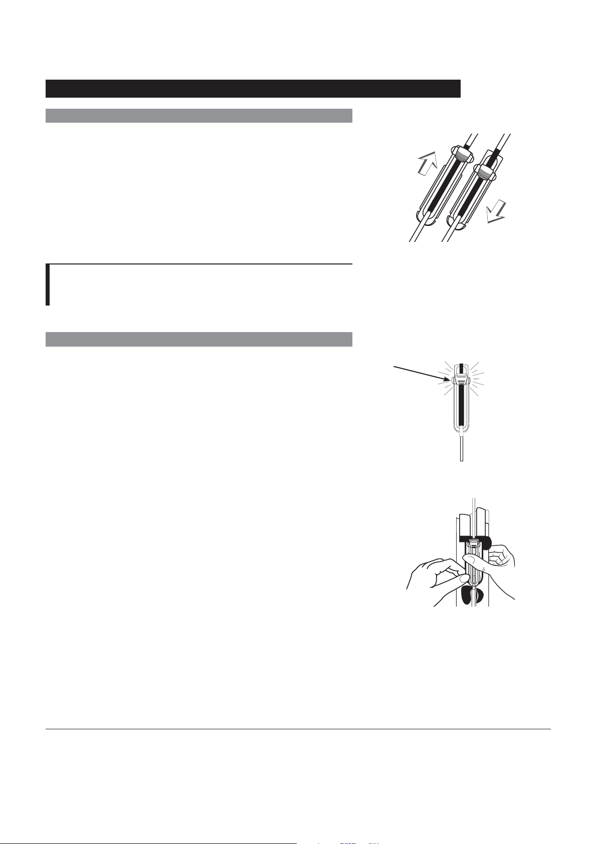
1. Slide Flow Regulator thumb clamp down until an audible
click verifies it is in fully closed position.
2. Spike solution container.
3. Fill drip chamber to 2/3 full.
À
4. Invert Flow Regulator.
Directions for Use
Alaris® SE Pump
Models 7130/7131, 7230/7231
Flow Regulator
Thumb Clamp
Click
Getting Started
15
Administration Set Information (Continued)
Preparing Solution Container and Set (Continued)
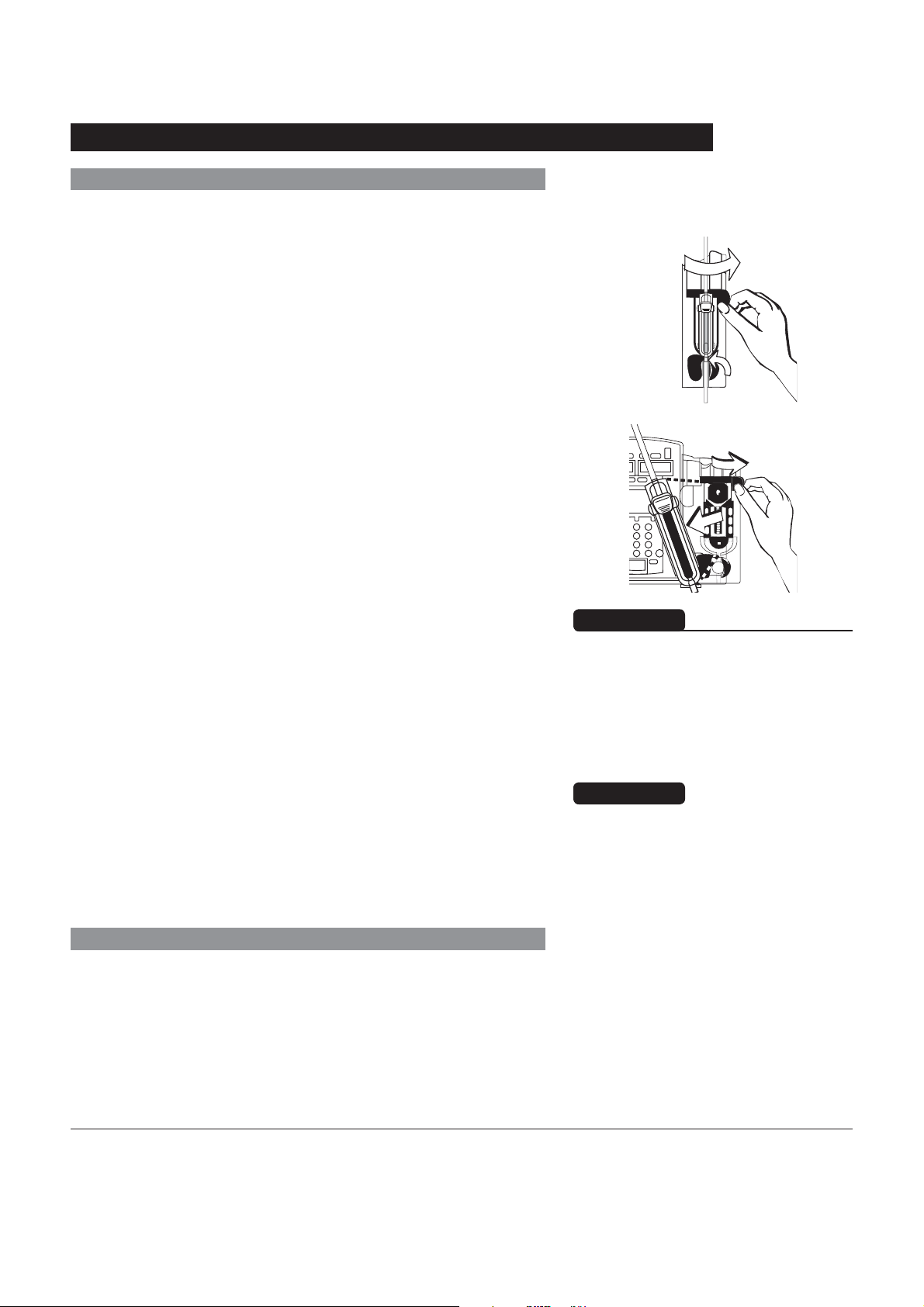
5. Slide Flow Regulator thumb clamp to open position to
slowly prime set.
6. Close Flow Regulator clamp when priming is complete, as
in Step 1. Verify no fluid is flowing.
7. A gravity flow rate may be adjusted with Flow Regulator
thumb clamp, if desired.
NOTE:
À Open the vent cap on the spike if the container requires
venting.
Loading Set
1. Slide Flow Regulator thumb clamp down until an audible
click verifies it is in fully closed position.
Slide up to open
for priming.
Slide down to
close for loading.
Thumb Clamp
Click
2. Using both hands, press top and bottom of Flow Regulator
into instrument until it snaps into place.
a. Verify 3 gray fingers (clamp arms) on each side of
pumping mechanism have engaged Flow Regulator.
b. Let go of set. A properly loaded set should stay in
instrument.
16
Getting Started
Flow Regulator
AC
Directions for Use
Alaris® SE Pump
Models 7130/7131, 7230/7231

Administration Set Information (Continued)
Loading Set (Continued)
3. Press firmly just below blue thumb clamp on Flow
Regulator with one hand while using other hand to close
latch fully to left.
• If resistance is met while closing latch, remove set,
verify Flow Regulator is fully closed and then reinstall
set.
• Verify thumb clamp has moved to open (up) position
prior to starting infusion.
WARNING
After set installation, verify no fluid
is flowing through the administration
set’s drip chamber, to avoid freeflow.
CAUTION
Before operating instrument, verify
that administration set is free from
kinks and installed correctly in
instrument.
4. Attach set to patient’s vascular access device.
5. Verify flow from IV container after starting infusion.
Directions for Use
Alaris® SE Pump
Models 7130/7131, 7230/7231
Getting Started
17
Administration Set Information (Continued)
Removing Set
1. Place channel on hold.
2. Open latch.
• Flow Regulator automatically closes to prevent
accidental unintended flow.
3. Press latch fully to right.
• Set is ejected from instrument.
IV
Changing Solution Container
1. Place channel on hold.
2. Remove empty solution container.
3. Spike new container.
4. Ensure drip chamber is filled to 2/3 full.
WARNING
Even though the instrument
automatically closes the Flow
Regulator, verify the Flow
Regulator is closed when the set
is removed from the instrument to
prevent unintended flow.
CAUTION
Do not attempt to force the set
from the instrument. Send the
instrument to qualified service
personnel.
18
Getting Started
Directions for Use
Alaris® SE Pump
Models 7130/7131, 7230/7231
References throughout this procedure to specific drugs and
drug doses are for illustration purposes only. Refer to specific
drug product labeling for information concerning appropriate
administration techniques and dosages.
Programming and Navigation Tips
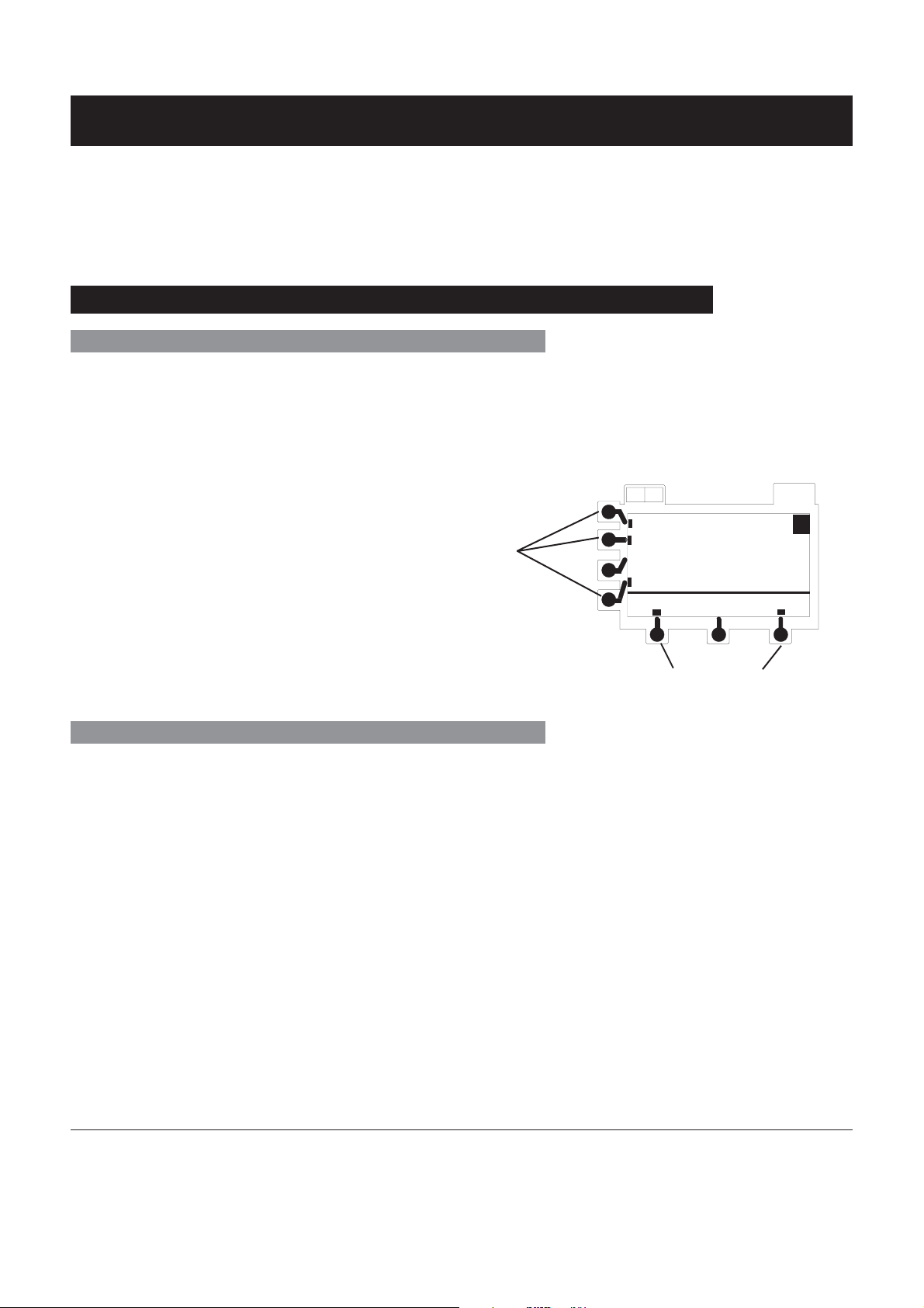
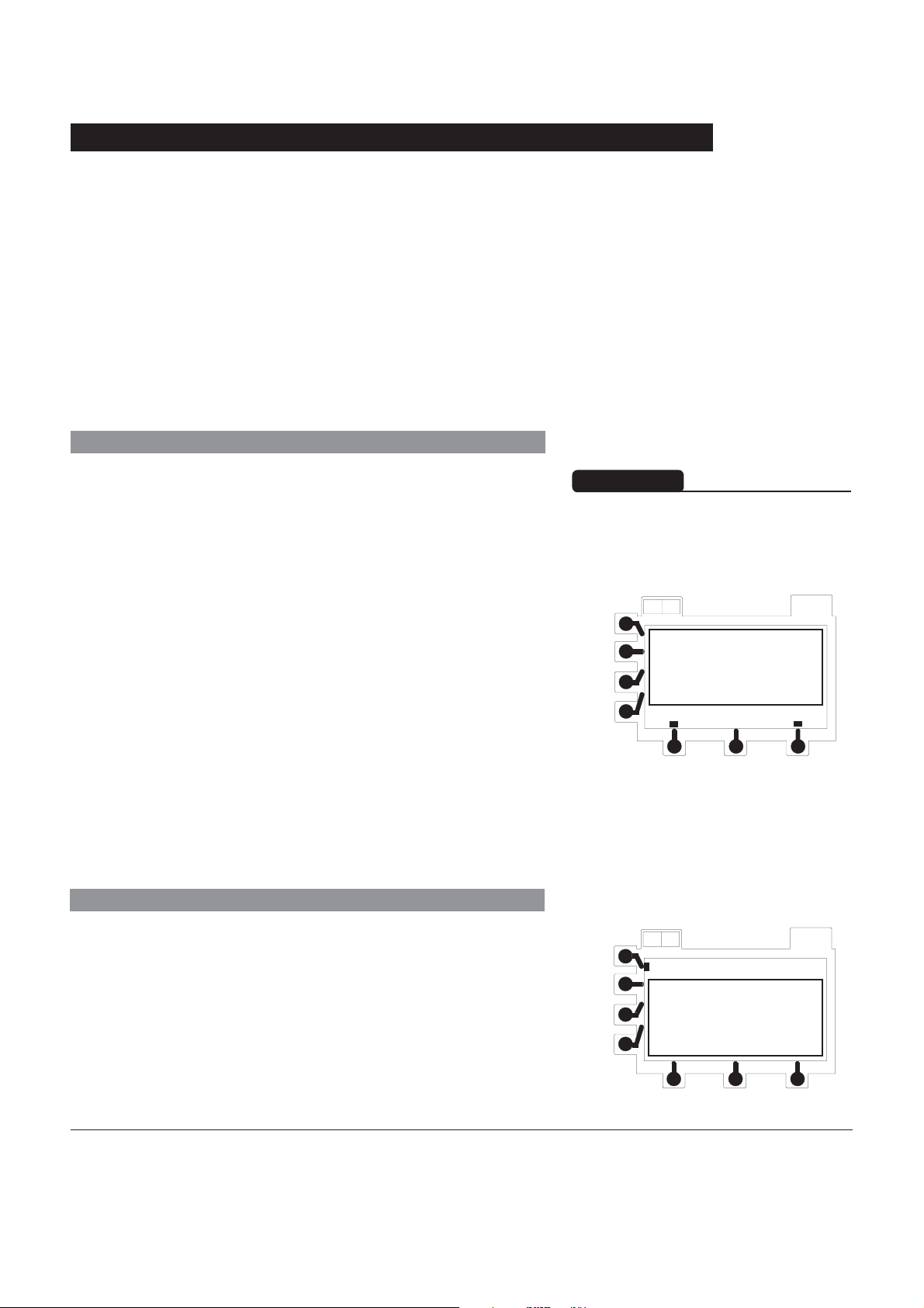
Soft Keys
Soft Keys are the keys located on the left side and the bottom
of the main LCD display. They serve a variety of functions, as
indicated by the text in the display at the time. A soft key is
active if there is a tick mark (y) next to the key.
If there is no tick mark next to the key, then it is not active
and cannot be selected. [In the illustrated example Conc
(concentration) is not active.] Pressing an inactive key results
in an invalid keypress tone.
Active Soft Keys
Programming
AB
Rate = 56.0 mL/h
Dose= 0.8 mg/kg/h
Conc= 100 mg/ 100 mL
Wt= 70 kg
menu
OPTIONS
ok
A
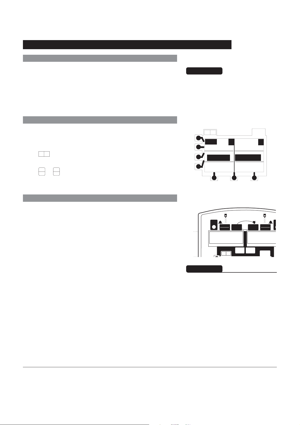
Entering Values
To enter programming values, select the desired parameter by
pressing the corresponding soft key. The field is highlighted.
To enter desired value, use the numeric keys then press the
ENTER key.
A value must be highlighted to be changed.
A flashing highlight indicates that the entry is incomplete.
Complete the entry and press the ENTER key.
To clear an existing value, press the CLEAR key. If the existing
value should not be cleared, pressing the CLEAR key a
second time (before pressing the ENTER key) restores that
value.
When all parameters required on a programming setup screen
have been entered, the ok soft key is used to confirm all
entries and continue programming.
Active Soft Keys
Directions for Use
Alaris® SE Pump
Models 7130/7131, 7230/7231
Programming
19
Programming and Navigation Tips (Continued)
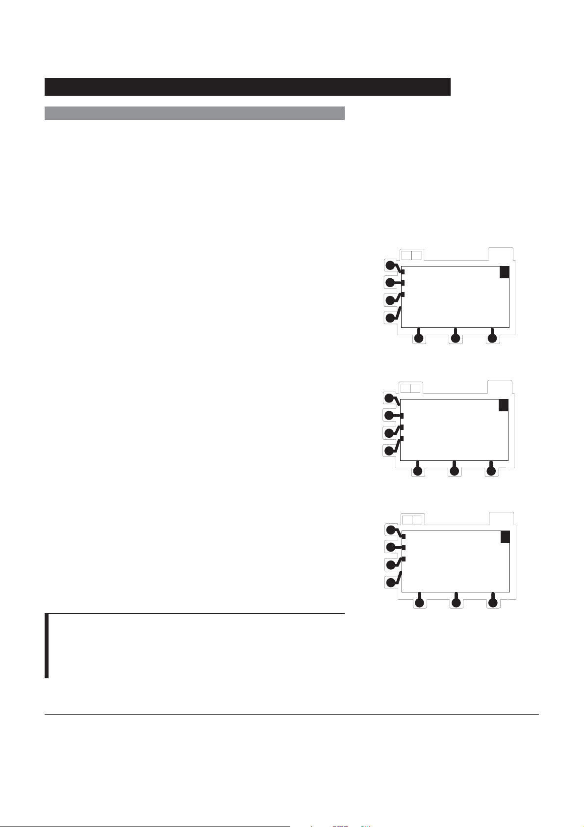
Menus - With Guardrails® Suite MX Protection
MENU screens provide access to the Profile drug libraries and
to basic programming in both the primary and the secondary
mode:
• MENU (Primary Main Menu)
• BOLUS MENU
• SECONDARY MENU
À
Press menu soft key while in primary programming mode to
display
MENU.
Press menu soft key while in bolus programming mode to
display
BOLUS MENU.
Press menu soft key while in secondary programming mode to
display
SECONDARY MENU.
AB
New Guardrails Drug
New Guardrails Fluid
Basic Infusion
MENU
AB
BOLUS MENU
Repeat Last Bolus
New Bolus
Quit Bolus
AB
Guardrails SEC Drug
Basic SEC
Return to PRI
OPTIONS
A
OPTIONS
A
OPTIONS
A
NOTE:
À When the Profiles feature is not enabled (Off), or when no
Data Set has been transferred to the SE Pump, Guardrails
Suite MX protection is not available and these menus do not
appear.
20
Programming
SECONDARY MENU
®
Directions for Use
Alaris® SE Pump
Models 7130/7131, 7230/7231
Programming and Navigation Tips (Continued)
K
Menus - NO Guardrails® Suite MX Protection
MENU screens for optional modes can be accessed using the
OPTIONS key:
• MULTI-STEP MENU
• MULTI-DOSE MENU
• DOSE RATE MENU
Split Screen (Dual Channel Only)
When both channels are infusing, a split screen showing
programmed information for both channels displays
automatically after one minute.
Press
Press
A B
key to switch immediately to split screen.
A
O
B
O
or
key to stop split screen.
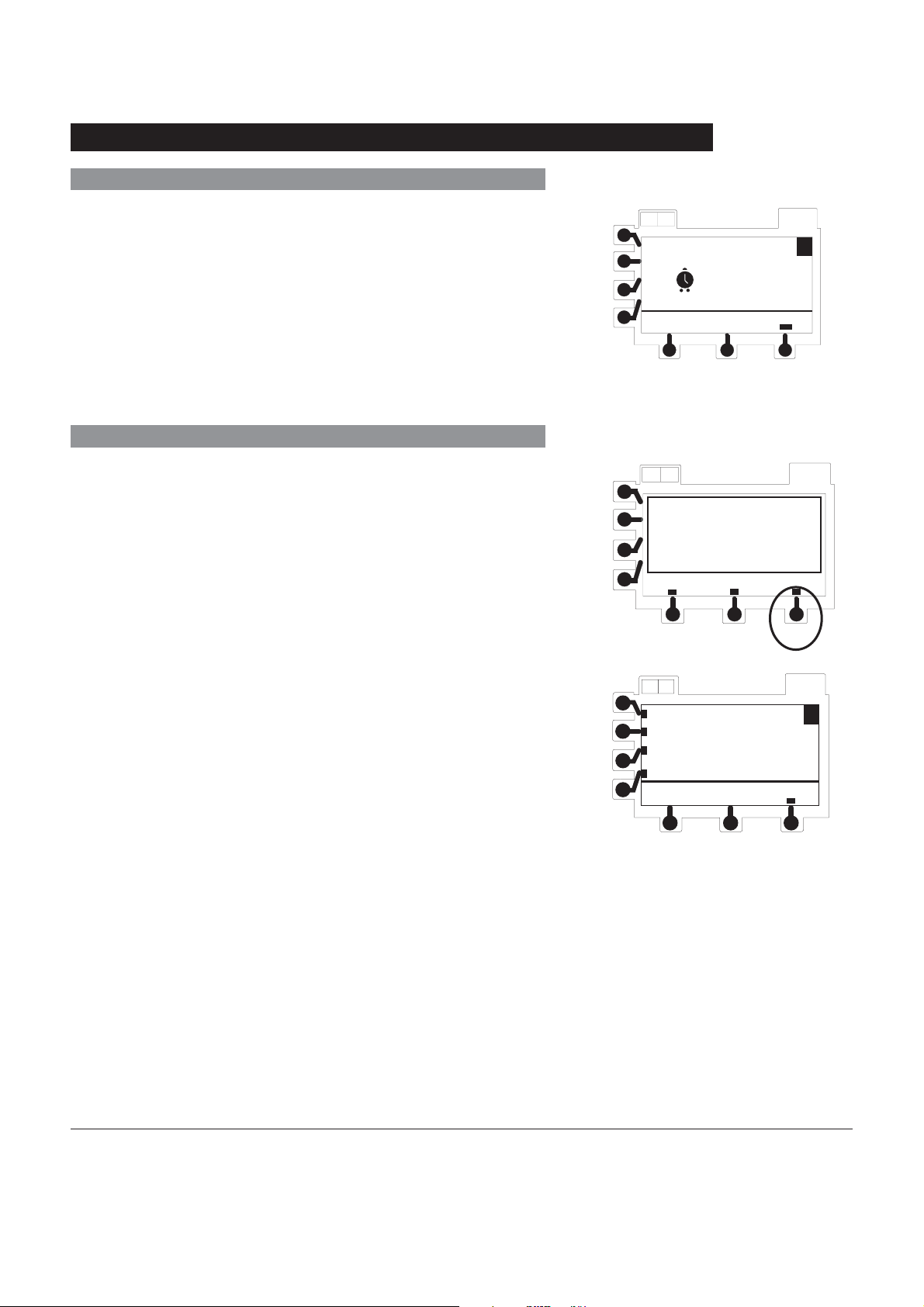
Powering On and Off
1. To turn channel on, press channel's POWER key.
CAUTION
Guardrails® Suite MX protection is
not available within the MULTI-STEP,
MULTI-DOSE OR DOSE-RATE
MENU options.
AB
Fluid
Rate = 75.0
0.9% NS
VI = 40.9
A
5
mcg/kg/min
DOPamine
VI = 0.5
OPTIONS
B
• Instrument performs a self test when first channel is
powered on.
• All indicators and displays momentarily light.
• An audio tone sounds.
• Hold indicator flashes.
-- Continued Next Page --
A
RUN
HOLD
HLD PRI SECKVO OPT
A B
POWER
ml/hr
PRI
PRI SEC HLD
POWER
SEC
RUN
HOLD
OPTIONS
OPT
WARNING
Each time the instrument is
turned on verify and/or set the
monitoring mode, resistance alert
and/or pressure alarm limit. If the
monitoring mode, resistance alert
and/or pressure alarm limit are not
verified, the instrument may not be
operating with the desired occlusion
detection parameter(s).
ml
Directions for Use
Alaris® SE Pump
Models 7130/7131, 7230/7231
Programming
21
Programming and Navigation Tips (Continued)
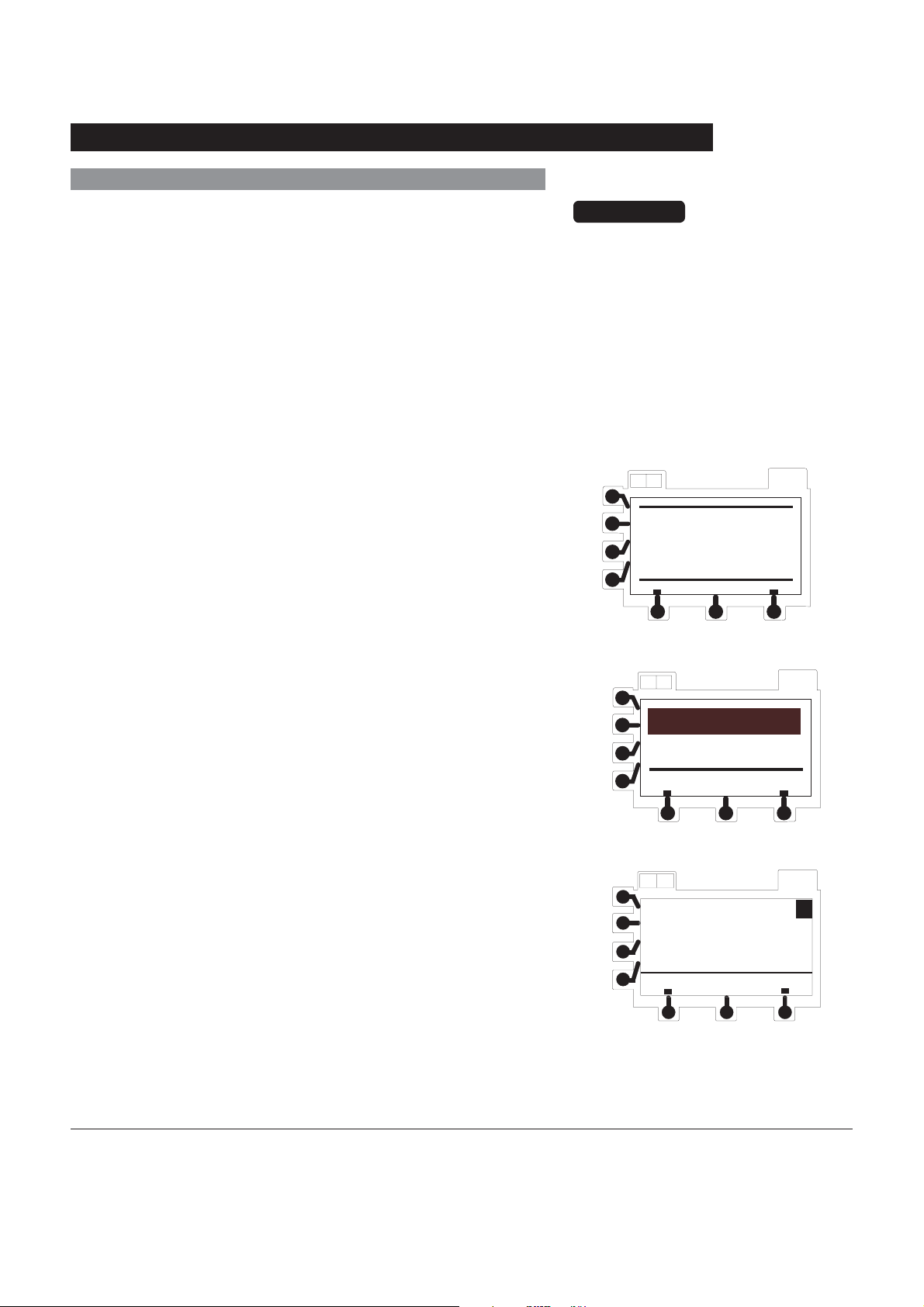
Powering On and Off (Continued)
• System startup page displays briefly (08.XX in
example display represents current software
revision; ID No. is instrument serial number).
CAUTIONS
• Appearance of lines and/or dots
that remain on constantly when
the instrument is powered on may
indicate improper functioning of
the Main Display. Although the
instrument is functioning, return it
to qualified service personnel.
• Inspect LCD for anomalies
(improperly lit/unlit pixels).
AB
© 2002, 2006
Cardinal Health
SW Rev. : 08.xx
ID No. : - - - - - - - - -
OPTIONS
• When self test completes, if Guardrails® Suite MX
protection is available, current profile screen appears.
• If Profiles feature is not enabled, then NEW PATIENT?
screen appears.
2. To power off, press and hold POWER key until display
turns off.
AB
Hospital Name
DataSet ID 123456789
Current Profile Is
Adult ICU
Accept Change
AB
NEW PATIENT ?
"Yes" Clears Previous
Patient Data
no
yes
OPTIONS
OPTIONS
A
22
Programming
Directions for Use
Alaris® SE Pump
Models 7130/7131, 7230/7231
Programming and Navigation Tips (Continued)
Responding to Maintenance Reminder
If the Preventive Maintenance Reminder option is enabled and
the device is due for preventive maintenance a Maintenance
Reminder message appears at power up.
1. Notify appropriate facility personnel if a Maintenance
Reminder message appears.
2. If necessary, press continue soft key to temporarily
bypass reminder.
Responding to Time Set Reminder
Following certain battery depleted conditions it is necessary to
re-set the internal clock so that CQI Reporter data integrity is
maintained. In such cases, a Verify Time reminder message
appears at power up.
AB
AB
Accept
Maintenace
Reminder
continue
Verify Date / Time
Feb 28 2006
16:43
Skip
OPTIONS
A
OPTIONS
Change
1. Press Change soft key.
• Time set screen displays.
2. Press soft key next to parameter to be changed.
• Current value is highlighted.
3. To enter a new value, use numeric keypad, then press
ENTER key.
4. Verify that all fields are correct then press ok soft key to
continue programming.
AB
Month
Day
Year
Time
02
28
2006
16h 43min
ok
OPTIONS
A
Directions for Use
Alaris® SE Pump
Models 7130/7131, 7230/7231
Programming
23
Guardrails® Suite MX Prompts
Guardrails® Suite MX software allows the facility to create
Soft and/or Hard Limits for Guardrails
Concentration, Guardrails
Administration Rate, Guardrails
®
Bolus Dose, Bolus Dose
®
®
continuous dose,
intermittent total dose,
Intermittent Time, and IV Fluid Rate.
Within each profile the facility may also pre-define the following
Hard Limits: maximum patient weight (kg), maximum patient
body surface area (m
2
) and maximum rate (mL/h).
Additional prompts are provided if Time or VTBI are edited
resulting in a rate change, or if a VTBI significantly larger or
smaller than the bag volume is entered.
Soft Limits
If programmed parameter is outside Soft Limit for that care area,
a prompt appears before programming can continue.
1. If it is inappropriate to override Soft Limit, press no soft key.
• Drug set up page displays.
2. Use numeric keys to enter a new value, then press ENTER
key.
WARNING
Prior to overriding a Soft Limit
prompt, confirm the infusion
parameters are correct.
AB
OPTIONS
OR
3. If it is clinically appropriate and necessary to override
Soft Limit, press yes soft key.
• Programming may continue.
When a maximum dose limit is exceeded,
↑↑↑ precedes the drug
or fluid name. This indicates that the drug is infusing at a rate
exceeding the defined maximum limit for that profile.
When a minimum dose limit is exceeded,
↓↓↓ precedes the drug
or fluid name. This indicates that the drug is infusing at a rate
less than the defined minimum limit for that profile.
Hard Limits
If programmed parameter is outside the Hard Limit for that care
area, a prompt appears indicating a value within range must be
entered before programming can continue.
Use numeric keys to enter a new value, then press ENTER
key.
alteplase
Exceeds Soft Limit:
0.81 mg/kg/h
Override Dose Limit?
no
AB
Rate = 600.0 mL/h
override?
DOPAmine
Exceeds Hard Limit:
50 mcg/kg/min
REPROGRAM
yes
OPTIONS
24
Programming
Directions for Use
Alaris® SE Pump
Models 7130/7131, 7230/7231
 Loading...