

Page 1
Title: Alaris Infusion Pump
Date: 7-29-2010
Rev 11-11-11 Update Disclaimer
Rev 5-20-12 Illustrate air-in-line.
DISCLAIMER: THIS PROCEDURE PROVIDED
"AS IS" AND WITH POSSIBLE FAULTS. USER
MUST VERIFY BEFORE USE. NEITHER
PROVIDER NOR WEBSITE ASSUMES ANY
RESPONSIBILITY FOR ITS USE.
File = alaris3.doc
1. General
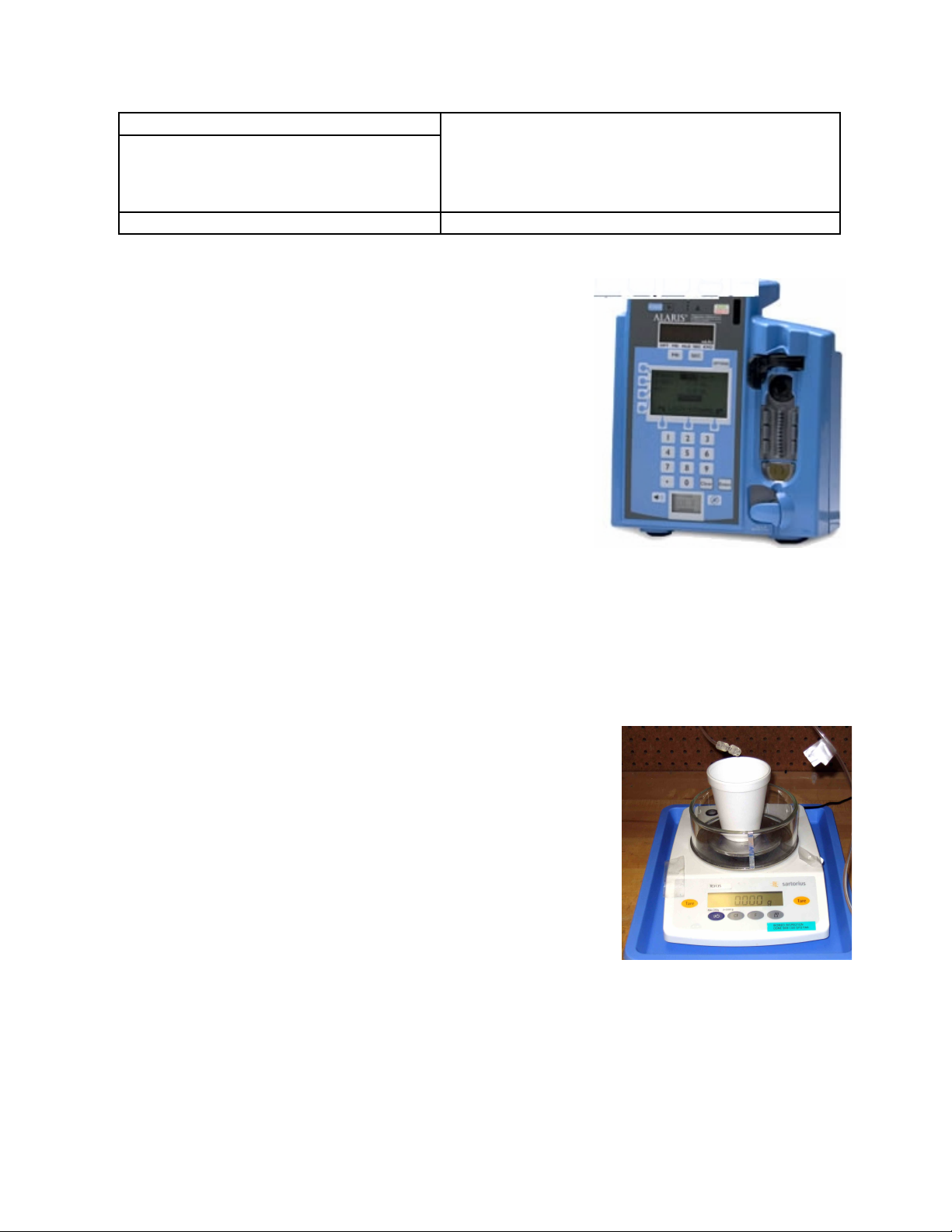
Applies to the Alaris Models 7100 thru 7200.
Example: Model 7130
2. Reference Documents:
Technical Service Manual (Signature Edition)
Training Manual if available
3. Tools / Fixtures / Labels
Safety Tester
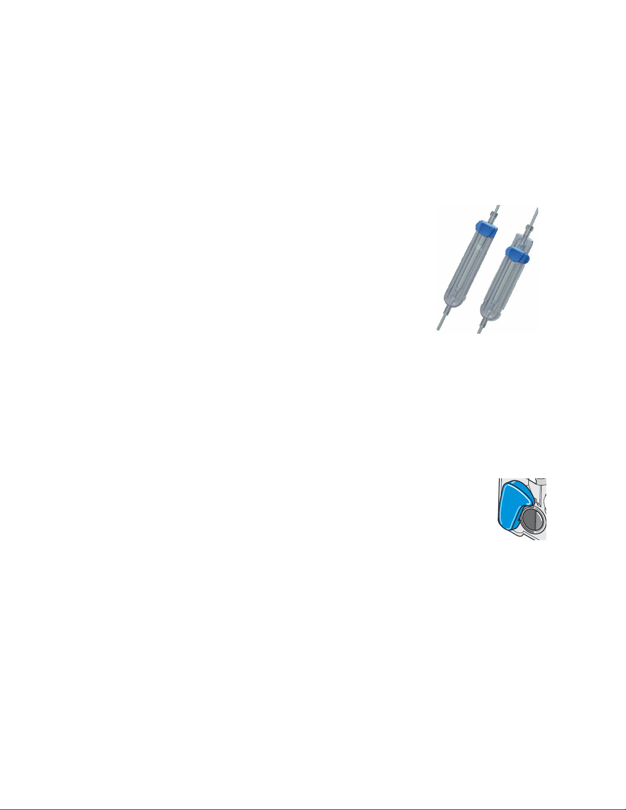
Ivac Signature Administration Set (AccuSlide)
Scale accurate to 0.1 gram (preferred method) and cup for
collecting output of pump. See picture.
Green Write-on Label Veriad P/N 171332
Clear Shield Label Veriad P/N US408
4. Initial Inspection
4.1. Check labels, cleanliness, line cord, cracks in cabinet.
4.2. Exercise the latch mechanism, checking for normal movement.
4.3. Check appearance of peristaltic cam actuators.
4.4. Mounting bracket and its knob/screw.
4.5. Check tightness of cable strap screw.
4.6. Air-in-Line detecting surface must be clean. There is a
small note on the front case pointing to this spot.
5. Setup and Diagnostics
5.1. While holding down the upper left-hand soft key, press
the power-on button; this opens the unit in the diagnostic
mode.
Note: Hit <page> to “scroll” forward.
5.2. Check Date/time and update if necessary
5.3. Reset the PM interval.
Note: Electrical Safety: Use the strap metal button as a contact for the following.
Loosen and then re-tighten this screw to insure good chassis contact. Holding your gnd
lead tight to button helps.
5.4. Using the safety tester, check that leakage with ground open is less than 100 uA
(“Case In” on some testers).
5.5. Using the safety tester, check that ground lead resistance is less than 0.100 ohms.
Page 2
5.6. Fan Check: Turn unit on unplugged; then plug in line cord. Normal faint fan noise
should now be heard. Recommended: Blow dust from fan housing after first
removing battery for access.
5.7. Battery Check: The Measured capacity > should be greater than the assigned
capacity. After a ½ hr charge, the bat bar graph should be at least 50%. If not, see
appendix for the Battery Refresh procedure.
6. Flow, Rate, Occlusion, Air-in-line, and Pressure Check
6.1. Turn unit on; <Accept>ing the current configuration (ICU for
example); Clear patient data <Yes>, and then hitting <Primary
Infusion> . Get administration set (see picture) ready by
insuring that it flows freely with no air bubbles apparent.
Note: The following for flow/volume is only a QuickCheck. See
Appendix when updating the volume cal factor is required.
6.2. Set Flow rate to 600ml/hr and Volume = 20mL.
6.3. Hit Run/Hold. With no cassette, get message “Set Out” etc.
6.4. Inset full cassette; press “Run/Hold”. In exactly 2 minutes, the
pump should deliver 20mL +/- 5% If outside this range, see
appendix.
Note: If display says “Instrument Self Check is Due”, follow on screen prompts and wait
for up to one minute for this internal task to finish.
6.5. Reprogram the unit for 7-9 mL volume; press <Run>.
6.6. Upstream Occlusion: As soon as the flow begins, pinch the upstream hose line.
Pump will halt and display “Occlusion upstream” or equivalent.
6.7. Silence Alarm: Now is good time to check this.
6.8. Downstream Occlusion: Restart the flow. Pinch the output hose. The unit often
displays “Checking Line” multiple times before finally halting with an Occlusion
message.
6.9. Air-in-Line: Before proceeding, clean both surfaces on the inner side of
the blue paddle with a damp Q-tip. False air alarms are often cured by
performing this. Run unit with empty cassette. Must get alarm.
6.10.Pressure Calibration (or check). If/when required, see Appendix.
7. Wrapup (depends on institution)
APPENDIX
Battery Refresh Cycle
1. Disconnect the battery; press the ON/OFF switch for 5 seconds; and reconnect the battery.
2. Plug unit in. Turn-on in the diagnostic mode. If software is 2.02 or higher, enter 0.0 aH in
the rated capacity for battery; hit OK. Re-enter 1.3 into the battery capacity field. Once
<ok> is pressed, cycle will start. Note that the battery bar graph will jump to 15-16 bars.
3. Leave connected to AC for 24 hours to complete cycle. The discharge, as shown by a
diminishing bar graph, will take several hours for just this phase.
Page 3

Flow Calibration
Note: Accuracies on the order of 1% are obtainable with this method. Protocols in the pump
software will not allow a straightforward change in the volume cal factor. Therefore for example, if
an initial volume check shows a result outside the 5% error range, the technician is required to
change the cal error to 0 (the only change allowed at this point) and run a second volume check.
After entering the results of this second check, a third and final check is then required.
1. Flow Calibration is done with a normal but factory pre-measured cassette, P/N 80VCS. Note
that it comes with a cal value (such as 39.1 on its accompanying sheet) which relates to the
volume delivered at 40 ml from a perfect pump.
2. Program the pump to run at 400 ml/hr with a volume limit of 40ml. If the collected result is
within 1% of the expected (39.1 in this case), the pump is in-cal. Compute
[(Vcollected/Vexpected)-1], where Vexpected is the cal number assigned to this “special”
cassette. A typical collection result, 38.5, as a percent would be -1.5%
3. If out of cal, one or more additional collections are now required. Turn the pump on in the
diagnostic mode and “page” over to page D4. Hit the soft key for Cal Rate. The re-cal
process forces the user to limit the next cal entry to only 0%. Do this by first hitting the
upper left softkey twice, and then enter 0.
4. Re-start unit, and then run another 40ml @ 400ml/hr check. Recalculate
[(Vcollected/Vexpected)-1]. If the result is within 1%, no more is required. Otherwise…
5. Return to diagnostics. In the rate cal location, enter the opposite of what “cal = 0 mode”
yielded in step 4 above.
6. Run a third and normally final volume check. [(Vcollected/Vexpected)-1] should calculate to
less than or equal to 0.01 (1%).
Pressure Calibration
Note: To check pressure without entering any data, note the last line on the “Cal Pressure” screen
aka “Sensor”. With 0 mmHg in, it should not exceed +/-2; at 500mmHg in, it should read 500 +/- 3.
1. Enter the diagnostic mode by holding down
upper left soft key and the hitting the power
button. Scroll/page to page D6 and hit <Cal
Pressure> button.
2. Install the pressure cassette (P/N 70ISS). Note
that the constants/offsets displayed may
change a small amount.
3. Be sure the pressurizing bulb is open so that
there is no line pressure. Press the “0 mmHg”
key; the resultant displayed constant will
usually slightly update and indicate “pass”,
however a “failure” message is not uncommon
and does not indicate a pump problem – only that the following steps must be taken.
4. Pump system up to 500mmHg and after a stable reading hit the “500 mmHg key”. Unit will
respond by updating the corresponding constant, indicate “pass”, and show “sensor = 499” or
a number very close.
5. Release circuit pressure and the sensor line should indicate 0000 +/- 1. Press <OK>.
6. Don’t forget to press <OK> above.
Page 4

Lifeguard Update
Note: The internal drug library is updatable, and requires a
Windows based PC/Laptop with an RS232 output cable.
1. Call up program “Data Set Transfer” (V2.0.1); connect the
RS232 to the Alaris unit. Complete the field “hospital name” and
the data set ID info; “VS5” is a recent example.
2. With the pump off, hit “Connect”, then turn pump on. Within
approximately 5 seconds, the bar graph in the transfer program
will begin to progress. (The displays on the pump will remain
blank.)
3. After “Transfer Complete” message, turn the pump on – this
will finalize the transfer. Be sure to re-attach connector cover.
4. The pump may be verified by using the diagnostic mode and paging through history.
I.D. : Date:
CASE INTEGRITY
FAN NOISE
LATCH MECHANISM
CLEAN THE AIR-IN-LINE
CHECK AIR-IN-LINE
DATE / TIME
RESET PM INTERVAL
GROUND RESISTANCE
CASE LEAKAGE
VOLUME ACCURACY
OCCLUSION (Upstream)
OCCLUSION (downstream)
PRESSURE CHECK
Battery Refresh Cycle
Update Guardrail?
Comments:
I.D. : Date:
CASE INTEGRITY
FAN NOISE
LATCH MECHANISM
CLEAN THE AIR-IN-LINE
CHECK AIR-IN-LINE
DATE / TIME
RESET PM INTERVAL
GROUND RESISTANCE
CASE LEAKAGE
VOLUME ACCURACY
OCCLUSION (Upstream)
OCCLUSION (downstream)
PRESSURE CHECK
Battery Refresh Cycle
Update Guardrail?
Comments:
I.D. : Date:
CASE INTEGRITY
FAN NOISE
LATCH MECHANISM
CLEAN THE AIR-IN-LINE
CHECK AIR-IN-LINE
DATE / TIME
RESET PM INTERVAL
GROUND RESISTANCE
CASE LEAKAGE
VOLUME ACCURACY
OCCLUSION (Upstream)
OCCLUSION (downstream)
PRESSURE CHECK
Battery Refresh Cycle
Update Guardrail?
Comments:
I.D. : Date:
CASE INTEGRITY
FAN NOISE
LATCH MECHANISM
CLEAN THE AIR-IN-LINE
CHECK AIR-IN-LINE
DATE / TIME
RESET PM INTERVAL
GROUND RESISTANCE
CASE LEAKAGE
VOLUME ACCURACY
OCCLUSION (Upstream)
OCCLUSION (downstream)
PRESSURE CHECK
Battery Refresh Cycle
Update Guardrail?
Comments:
 Loading...