

Page 1
HYDRO 15
5
5
5
5
5
5
5
5
5
5
1234
1234
1234
1234
1234
1234
1234
1234
1234
1234
1234
4
4
4
4
4
4
4
4
4
4
4
4
4
4
4
4
4
4
4
4
4
4
4
4
4
4
4
4
4
4
4
4
4
4
4
4
4
1
1
1
1
1
1
1
1
1
1
1
1
1
1
1
1
1
1
1
1
1
1
1
1
1
1
1
1
1
1
1
1
1
1
1
1
1
1
1
1
1
1
1
1
1
1
1
1
1
FLEX WING
MOWER
Published 09/06 Part No. 00756179S
PRODUCT SERVICE MANUAL
234
234
234
234
234
234
234
234
234
234
23
23
23
23
23
23
23
23
23
23
23
23
23
23
23
23
23
23
23
23
23
23
23
23
23
23
23
23
23
23
23
23
23
23
23
23
23
An operator's manual, parts manual was shipped with the unit shipped from the factory.
There may also be other information on this product available, assembly manual, insert
sheets and/or special instruction sheets. This manual is designed to be used in conjunction
with these other manuals and/or instruction sheets. This manual is not designed to replace
any of the other manual. The information is as of the published date, changes may be
made to unit without prior notice and/or changes to the tractors which will affect the
mounting. Alamo Industrial will not be responsible for the changes that may affect the
unit. If manuals are needed contact your local dealer or Alamo Industrial Inc.
ALAMO INDUSTRIAL
1502 E. Walnut
Seguin, T exas 78155
830-379-1480
© 2006 Alamo Industrial
Page 2

Page 3
TO THE OWNER/OPERA T OR/DEALER
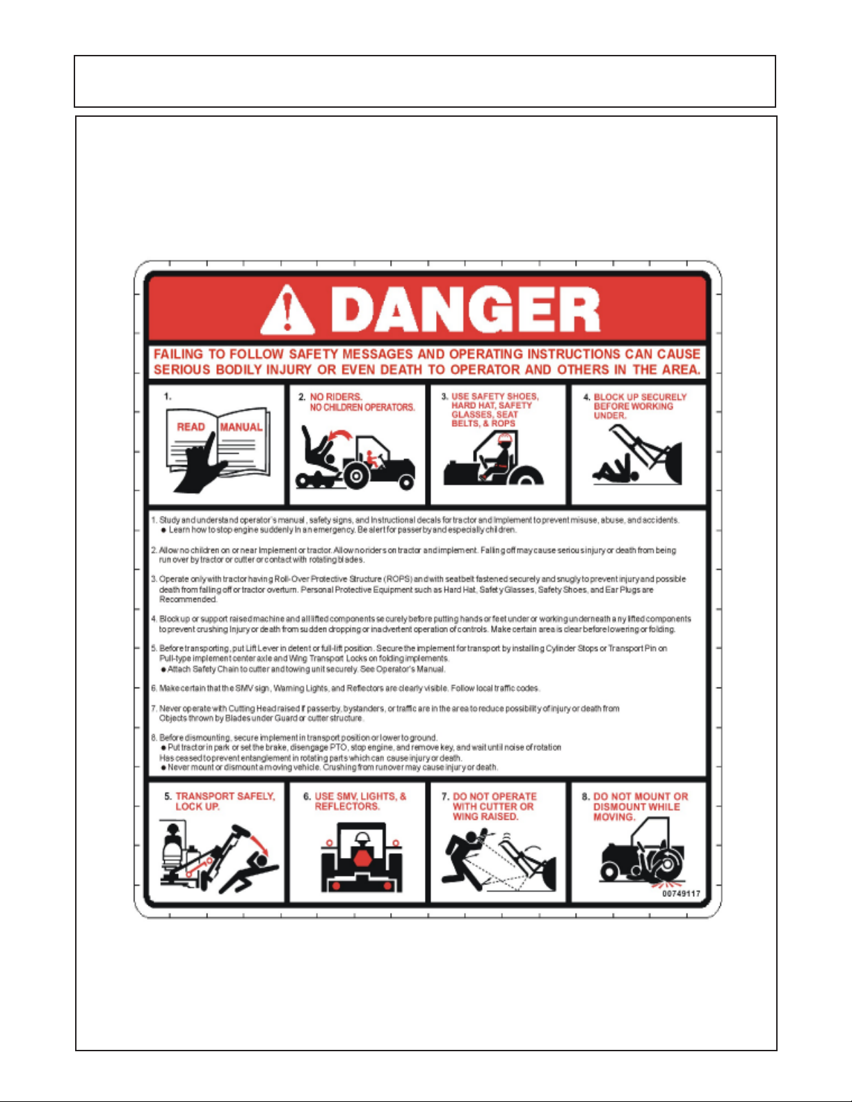
All implements with moving parts are potentially hazardous. There is no substitute for a cautious, safe-minded
operator who recognizes the potential hazards and follows reasonable safety practices. The manufacturer has
designed this implement to be used with all its safety equipment properly attached to minimize the chance of
accidents.
BEFORE YOU START!! Read the safety messages on the implement and shown in your manual.
Observe the rules of safety and common sense!
WARRANTY INFORMATION:
Read and understand the complete Warranty Statement found in this Manual. Fill out the Warranty Registration
Form in full and return it to within 30 Days. Make certain the Serial Number of the Machine is recorded on the
Warranty Card and on the Warranty Form that you retain.
Page 4

Page 5
INTRODUCTION
ABOUT THIS MANUAL:
The intent of this publications to provide the competent technician with the information necessary
to perform the CORRECT repairs to the Alamo Industrial Product. This will, in turn provide for complete
customer satisfaction
It is hoped that the information contained in this and other Manuals will provide enough detail to
eliminate the need for contact of the Alamo Industrial Technical Service Dept. However, it should be
understood that many instances may arrive wherein correspondence with the Manufacturer is necessary.
CONTACTING MANUFACTURER: (Please help us Help You! Before You Call! )
Alamo Industrial Service Staff Members are dedicated to helping you solve yours or your
customer’s service problem as quickly and efficiently as possible. Unfortunately, we receive entirely to
many calls with only a minimum amount of information. In some cases, the correspondent has never gone
out to look at the equipment and merely calls inquiring of the problems described to him by the operator
or customer.
PART NUMBERS: Part numbers listed in this manual are subject to change without notice as
designs are made to adapter to the tractor or for a design improvement. Before ordering parts ALWAYS
Measure old part to make certain that is the one you will need. This manual is designed to be used along
with the Parts and Operators Manual.
Most calls received by Alamo Industrial Service can be classified into approx. 6 general categories.
1. Hydraulic or Mechanical Trouble Shooting.
2. Request for Technical Information or Specifications.
3. Mounting or Fitting Problem.
4. Special Service Problem.
5. Equipment Application Problems.
6. Tractor Problem Inquiries.
HOW YOU CAN HELP:
Make sure the call is necessary! Most of the calls received may not be necessary if the Dealer
Service Technician would do the following.
1. Check the Service Information at your Dealership provided by Alamo Industrial, This would
include, Service Bulletins, Information Bulletins, Parts Manuals, Operators Manuals or
Service Manuals, many of these are available via the Alamo Industrial Internet site (Alamo - Industrial.
Com). Attempt to diagnose or repair problem before calling.
2. If a call to Alamo Industrial is needed, Certain Information should be available and ready
for the Alamo Industrial Service Staff. Such information as, Machine Model, Serial Number, Your Dealer
Name, Your Account Number and Any other information that will be useful. This information is vital for the
development of a prompt and correct solution to the problem. This will also help to develop a database
of problems and related solutions, which will expedite a solution to future problems of a similar nature.
3. The technician may be asked to provide detailed information about the problem including
the results of any required trouble shooting techniques. If the information is not available, The technician
may be asked to get the information and call back. Most recommendations for repairs will be based on
the procedures listed in the Service Manual / Trouble Shooting Guide.
CONTACT ALAMO INDUSTRIAL:
Alamo Industrial, 1502 E. Walnut St. Seguin TX. 78155,
Technical Service Dept. PH: 830-379-1480
HYDRO 15 (Service Manual) 09/06
© 2006 Alamo Group Inc.
Index -1
Page 6

INDEX
Section Page
Section 1 - Specifications...........................................................................1-1 to 1-7
Do Not Do or Allow Items (Read First Thing).......................... 1-2
Mower Specifications...........................................................1-3 to 1-5
Bolt Torque Specifications Chart........................................... 1-5
Pump & Motor Hydraulic Schematic - 15 Foot Model..............1-6
Pump & Motor Hydraulic Schematic - 10 Foot Model..............1-7
Section 2 - Pump Service & Repair.......................................................... 2-1 to 2- 22
Pump Repair Preparation Procedures................................... 2-2
Pump Test Procedure..........................................................2-3 to 2-4
Pump & Motor Hydraulic Schematic - 15 Foot Model..............2-5
Pump & Motor Hydraulic Schematic - 10 Foot Model..............2-6
Recommended & Required Tools.......................................... 2-7
Pump Cleaning & Removal................................................... 2-8
Pump Component Identification............................................ 2-9
Pump Dis-Assembly Preparations........................................ 2-10
Pump Dis-Assembly Procedures.......................................... 2-11 to 2-13
Pump Component Wear Inspection Guide............................. 2-14
Pump Assembly Preparation................................................2-15
Pump Assembly Procedures................................................2-16 to 2-21
Pump Recommended Start Up Procedure............................. 2-22
Section 3 - Motor Service & Repair..........................................................3-1 to 3-25
Motor Repair Preparation Procedures...................................3-2
Motor Test Procedure.......................................................... 3-3 to 3-4
Motor & Pump Hydraulic Schematic - 15 Foot Model..............3-5
Motor & Pump Hydraulic Schematic - 10 Foot Model..............3-6
Recommended & Required Tools.......................................... 3-7
Motor Cleaning & Removal................................................... 3-8
Motor Identification Center & Wings...................................... 3-8 to 3-9
Motor Dis-Assembly Preparation (Center)..............................3-10
Motor Dis-Assembly Preparation (Wings).............................. 3-11
Motor Component Identification.............................................3-12
Motor Dis-Assembly Procedures.......................................... 3-12 to 3-15
Motor Component Wear Inspection Guide.............................. 3-16
Motor Assembly Preparation................................................ 3-17
Motor Assembly Procedures................................................ 3-17 to 3-23
Motor Recommended Start Up Procedure.............................. 3-24
Motor Electrical System (wing Motors).................................. 3-24 to 3-25
Section 4 - Spindle Repair......................................................................... 4-1 to 4-10
Spindle Component Identification.......................................... 4-2
Blade Carrier Removal..........................................................4-9 TO 4-10
Spindle Removal Preparation................................................ 4-2
Spindle Housing Removal.....................................................4-2 to 4-3
Spindle Housing Dis-Assembly.............................................4-3 to 4-5
Spindle Component Inspection Part Condition........................4-5
Spindle Assembly Procedure............................................... 4-5 to 4-9
Blade Carrier Installation...................................................... 4-9 to 4-10
HYDRO 15 (Service Manual) 09/06
© 2006 Alamo Group Inc.
Index -2
Page 7

INDEX
Section Page
Section 4 - Spindle Repair......................................................................... 4-1 to 4-10
Spindle Component Identification........................................................ 4-2
Blade Carrier Removal........................................................................4-9 TO 4-10
Spindle Removal Preparation.............................................................. 4-2
Spindle Housing Removal...................................................................4-2 to 4-3
Spindle Housing Dis-Assembly...........................................................4-3 to 4-5
Spindle Component Inspection Part Condition...................................... 4-5
Spindle Assembly Procedure..............................................................4-5 to 4-9
Blade Carrier Installation.................................................................... 4-9 to 4-10
Section 5 - Hydraulic Cylinder Repair & Service.................................... 5-1 to 5-30
Wing Lift Cylinders
Wing Lift & Fold Cylinder Schematic 15 ft............................................ 5-2 & 5-4
Wing Lift & Fold Cylinder Schematic 10 ft............................................ 5-3 & 5-5
Wing Lift & Fold Cylinder Removal...................................................... 5-8
Wing Lift & Fold Cylinder Dis-Assembly.............................................. 5-8 to 5-10
Wing Lift & Fold Cylinder Re-Assembly............................................... 5-10 to 5-14
Standard Axle Lift Cylinder (Standard 1 Cylinder System)
Axle Lift Cylinder Schematic (Standard 1 Cylinder 15 ft)........................5-2
Axle Lift Cylinder Schematic (Standard 1 Cylinder 10 ft)........................5-3
Axle Lift Cylinder Removal (Standard 1 Cylinder).................................. 5-16
Axle Lift Cylinder Dis-Assembly (Standard 1 Cylinder).......................... 5-16 to 5-18
Axle Lift Cylinder Component Inspection (Standard 1 Cylinder)............. 5-19
Axle Lift Cylinder Re-Assembly (Standard 1 Cylinder)........................... 5-19 to 5-21
Optional Axle Lift Cylinder (Optional 3 Cylinder System)
Axle Lift Cylinder Schematic (Optional 3 Cylinder 15 ft).........................5-4
Axle Lift Cylinder Schematic (Optional 3 Cylinder 10 ft).........................5-5
Axle Lift Cylinder Removal (Optional 3 Cylinder Axle Level Lift).............. 5-24
Axle Lift Cylinder Dis-Assembly (Optional 3 Cylinder Axle Level Lift)..... 5-24 to 5-26
Axle Lift Cylinder Component Inspection (Optional 3 Cyl Axle Level Lift). 5-26 to 5-27
Axle Lift Cylinder Re-Assembly (Optional 3 Cylinder Axle Level Lift)...... 5-28 to 5-30
Section 6 - Hydraulic Tank Repair, Fill And Service............................... 6-1 to 6-5
Hydraulic Tank Fluid Level................................................................. 6-2
Hydraulic Tank Oil Return Filter.......................................................... 6-3
Hydraulic Tank Oil Fill Procedure........................................................ 6-4 to 6-5
Section 7 - Speed Increaser (Speed Changer) Repair & Service......... 7-1 to 7-13
Speed Increaser To Tractor PTO Mount............................................... 7-2 to 7-5
Speed Increaser Component Identification............................................ 7-6 to 7-7
Speed Increaser Dis-Assembly For Component Inspection....................7- 8
Speed Increaser Dis-Assembly For Component Re-Placement.............. 7-8 to 7-9
Speed Increaser Re-Assembly For Component Re-Placement...............7-10 to 7-13
Section 8 - Tire - Wheel - Hub Repair & Service..................................... 8-1 to 8-7
Wheel Information..............................................................................8-2 to 8-3
Wheel Hub Dis-Assembly.................................................................. 8-3 to 8-4
Wheel Hub Re-Assembly................................................................... 8-5 to 8-7
HYDRO 15 (Service Manual) 09/06
© 2006 Alamo Group Inc.
Index -3
Page 8

INDEX
Section 9 - Blades & Blade Carriers Service & Repair.......................... 9-1 to 9-3
Blade Carrier Service & Repair............................................................ 9-2
Blade Bolt Service & Repair............................................................... 9-3
Section 10 - leveling Mower Service & Repair........................................10-1 to 10-6
Tongue Clevis Connection.................................................................. 10-2
Leveling Rod Component Identification................................................. 10-3
Assembling Control Rods...................................................... 10-4
Adjusting Control Rods..................................................................... 10-5
Adjusting Wing Axles........................................................................ 10-6
Leveling Mower..................................................................................10-1 to 10-6
Section 11 - Trouble Shooting Guide........................................................ 11-1 to 11-3
Probable Cause & Solutions...............................................................11-2 to 11-3
HYDRO 15 (Service Manual) 09/06
© 2006 Alamo Group Inc.
Index -4
Page 9

Section 1
HYDRO 15
Model
HYDRO 15 (Service Manual) 09/06
© 2006 Alamo Industrial
Specifications
Section 1 - 1
Page 10

SPECIFICATIONS - HYDRO 15 FLEX WING
READ THIS BEFORE BEGINNING
ASSEMBLY, REPAIRS OR TESTING:
The Hydro 15 has electric components:. The electric components can be damaged if care is not
taken when performing repairs, testing, dis-assembly or re-assembly. Mower must be maintained in a safe
position at all times. The hydraulic system must be protected from contamination at all times.
DO NOT
1. DO NOT start any repairs, testing or dis-assembly before the mower is secured with the wings in the lowered
position and the mower hydraulic axle system released to lower the mower completely. If the Hydraulic axle
cylinders or turnbuckles are to be removed or serviced make certain mower decks are securely supported
by strong jack stands. Make certain mower is in secure clean environment when working on hydraulic system.
If mower is connected to tractor must be secured to prevent someone from starting it and parked in accordance
with the tractor manufactures recommendation, See tractor operators manual and/or decals for parking tractor
securely.
2.
DO NOT open any hydraulic component on mower before the entire exterior of the mower and hydraulic
components have been cleaned of all debris or any thing that would contaminate the hydraulic system. When
working on the hydraulics always keep the hoses sealed by using temporary caps to plug them, do not just
leave them open to the elements
3. DO NOT short any wires across or allow them to be shorted out on the electric components of mower. Do not
allow or attempt to jump across any wires or supply them with alternate power source.
4. DO NOT install higher rated fuses than are recommended by manufacturer for any components.
5. DO NOT do any welding on unit unless the electrical components are unplugged first, this is to prevent a power
surge going into switch and/or solenoids (THIS IS VERY IMPORTANT). This could also apply to the tractor
components. Check Tractors repair guide for specific instruction about tractor model and type.It is recommended that mower be disconnected from tractor when being repaired.
6. DO NOT attempt to repair or adjust a component that is not intended to be repaired, example sealed components
as there are no serviceable components inside.
7. DO NOT let anyone attempt any testing or repairs unless they are an experienced and qualified technician.
Technicians must have proper tools, gauges, meters etc. to perform proper diagnosis and/or repairs.
8. DO NOT perform any repairs with dirty tools or in dirty area. When working on hydraulic components, keeping
system clean and free of contamination is important.
9. DO NOT re-use old oil if it is contaminated, re-install dirty components or not completely clean the system after
a repair if there is a possibility of oil contamination. Example: If the right wing motor has metal in it from a failure
the left wing motor is most likely also contaminated. The center motor, and possibly the pump, the hoses, the
tank, the filter housings as well as the filters will most likely need cleaning and or replacing.
10. DO NOT start or engage system if the oil level is not at the proper level or condition. Never start or run unit low
or out of oil.
11. DO NOT install / add any oil unless you know it is the correct type and the container is clean. Make certain
the oil is not contaminated with dirt or any liquid. It is recommended that any oil installed be done using a
commercial oil buggy with a filtered system, a buggy system can also be used to clean the oil.
HYDRO 15 (Service Manual) 09/06
© 2006 Alamo Industrial
Section 1 - 2
Page 11

SPECIFICATIONS - HYDRO 15 FLEX WING
General Specifications for Mower:
Tractor Horse Power Required........................................ 70 - 90 HP
Tractor PTO RPM......................................................... 540 RPM required
Mower Paint Colors....................................................... Alamo Yellow Std / Other Colors Optional
Mower Gross Weight.....................................................4200 lbs. w/ Chain Guards (this can vary w/ wheel type)
Mower Tongue Weight................................................... Approx 2200 lbs w/ Wings lowered
Cutting Capacity........................................................... Grass & Up To 1-1/2" dia Brush (Max)
Mower Overall Length.................................................... 199" Front To Back
Mower Overall Width..................................................... 186.5" w/Wings Down & 96" w/ Wings Folded (this can
be affected by tire size, type, & wing axle adjustment)
Number Blade Carriers...................................................3 on 15 ft Model & 2 on 10 Ft Model
Cutting Width Options................................................... 15 Ft or 10 Ft Model
Over All Cutting Width... (15 Ft Model)................ 180" Center & Wings Overall Cutting Width
(10 Ft. Model)............... 124-1/2" Center & Wing Overall Cutting Width
Cutting Height...............................................................2" Down to 15" Up w/ 700:15 Pneumatic Tires (Cutting
Height will vary with tire & Wheel sizes)
2" Down to 12" Up w/ 12" Tires (Cutting Height will vary
with tire & Wheel sizes)
Blade Carrier Cutting Width............................................ Center & Wing
Center Section..................................................69" (Carrier Cutting Width - Overlap)
Left Wing..........................................................63-1/2" (Carrier Cutting Width - Overlap)
Right Wing....................................................... 63-1/2" (Carrier Cutting Width - Overlap)
Blade Over Lap Between Wing and Center...........8" total overlap (4" center overlap & 4" Wing overlap)
Blade Carrier Options.................................................... Pan or Bar Carrier
Bar Carrier Size................................................ Bar Carrier - 1-1/4" X 6" Bar Size
Pan Carrier Size............................................... Pan Carrier - 3/16" thick X 2-1/2" high X 37-1/4" dia. pan
w/ 1-1/4" X 6" steel bar w/ cross bar brace.
Blade Carrier Mounting.................................................. Bolts Direct to Blade Spindle f/ Under Side
Bolts........................................Qty 4
Type........................................ Allen Head Bolts
Torque..................................... 400 ft lbs
Installation............................... Use Thread L ock Compound
Lockwasher.............................. Qty 4
Blade Options.............................................................. Fan
Blade Size....................................................................1/2" thick X 3.5" wide X 22-1/4" long (measure blade
length from center of bolt hole to end of blade)
Blade Rotation.............................................................. CCW rotation Center & LH Wing, CW RH Wing
Blade Bolt Type............................................................ Bolt On W/ Locknut
Construction............................. Cold Forged and Hardened, w/ 1-1/8" square Shank,
Shoulder.................................. 1/2" High X 1-1/2" dia Shoulder, w/ 1" RH Thread,
Bolt Head................................. 2-7/16" Round Flat Head
Bushing....................................2" OD X 1-1/2" ID X 1-1/2" Long Welded into Blade Bar
Washer & Nut...........................1" Structural Steel Flat Washer & Toplock Locknut
Torque......................................300 ft lbs
Blade Tip Speed............................................................Blade Tip Speed Based on Max Pressure & RPM
Center Section Blade Tip Speed......................... 18,262 FPM (Operating Speed)
Wing Section Blade Tip Speed........................... 13,194 FPM (Operating Speed)
Blade Spindle.............................................................. 1 On Center Section & 1 On Each Wing
Spindle Bearing Type........................................ Adjustable Roller Bearing Cup & Cone)
Spindle Seal..................................................... Replaceble Round Seal Bottom & Gasket Seal Top
Spindle Lubrication............................................NLGI EP #2 Grease / Grease w/ Grease Gun
Spindle Bearing Preload (Required).....................Adjustable (
12 to 15 in. lbs. of rolling resistance)
HYDRO 15 (Service Manual) 09/06
© 2006 Alamo Industrial
Section 1 - 3
Page 12

SPECIFICATIONS - HYDRO 15 FLEX WING
Blade Spindle Speed .................................................... Measured RPM at Spindle Shaft
Center Section Spindle Tip Speed...................... 731 RPM (Operating Speed)
Wing Section Spindle Speed.............................. 881 RPM (Operating Speed)
Spindle to Deck Mounting Bolts......................... 3/4" Grade 8 Toque to 350 ft. lbs.
Hydraulic Pump, Tandem............................................. Front1/2 of Pump f/ Wing & Rear 1/2 pump of f/ Center
Pump Type...................................................... Tandem Gear Type - PTO Driven Via Speed Changer
Pump Displacement......................................... Center = 2.95 C.I.D. Wing = 3.6 C.I.D.
Pump HP......................................................... 145 HP Dual Stage Gear Type
Speed Changer Gear Ratio.................................1 RPM Input X 4 RPM Output (Increase)
Tractor PTO Speed............................................540 RPM Required
Pump RPM.......................................................2160 RPM Operating (2750 RPM Max)
Pump Pressure.................................................3000 PSI Operating (3600 PSI Max at Max RPM)
Pump GPM Front 1/2 (Wing Motors).............28 GPM Operating (35 GPM at Max RPM)
Rear 1/2 (Center Motor)............ 24 GPM Operating (35 GPM at Max RPM)
Hydraulic Motor, Center & Wing..................................... 1 & 2 on 15 ft Model / 1 & 1 on 10 ft Model
Motor Type...................................................... Gear Type
Motor HP Rating........... Center..........................75 HP @ 3000 PSI
Wing........................... 70 HP @ 2000 PSI
Motor Displacement.......................................... Center = 6.300 C.I.D. Wing = 6.375 C.I.D.
Motor Relief Valve Setting.................................. Center = 3000 PSI Wing = 2000 PSI
Motor Max Pressure......................................... Center = 3600 PSI Wing = 3000 PSI
Motor HP Rating at Operating RPM.................... Center = 37.8 HP Wing = 27.2 HP
Motor Tip Speed at Operating RPM.................... Center = 731 RPM Wing = 881 RPM
Motor Cut Off ... Wing Decks..............................Electric Cut Off Standard on Wings
Center Deck............................. Tractor PTO Shut Off For Center Deck Standard
Motor Mounting Type........................................ Bolts Direct to Blade Spindle Asy.
Motor To Spindle Mounting Bolt Size................. 1/2" Grade 8 Torque to 95 ft. lbs
Hydraulic Oil Type........................................................ 100AW or Equivalent SAE 30 Weight Hyd Oil
Hydraulic Oil Capacity.................................................. Tank & Cooling Tubes = 35 Gals
Hydraulic Tank..............................................................Weldment, Bolted to Center Section
Hydraulic Filter............................................................. 2 Micron Filter / Replaceable
Hydraulic Cooling Tube Type.......................................... 3" X 8" Deck Length Weldments (2 each wing & Center)
Hydraulic Reservoir Pressure......................................... 11 PSI (Return Pressure)
Mower Deck Leveling Adjustment................................... Mechanical f/ Front to Rear (at Assembly Setup &
Self Leveling While Operating)
Mower Center Deck Control Rods................................... Dual Control Rods.
Mower Hitch................................................................. Self Leveling
Axle Lifting............................... Standard...................... Hydraulic Cylinder Center Axle & Lift Screws on Wings
Optional....................... Hydraulic Cylinder on Center Axle and Wing Axle
Axle Lowering Height Stop......... Center Axle.................. Clip on Spacers Set Center Cylinder
Axle Shock Absorber................. Center..........................Rubber Bump Pads (Standard)
Wing............................Coil Springs each Wing Axle (Standard)
Mower Wing Leveling.................Standard...................... Wing Axle mechanical Screw Lift Adjustment
Optional....................... Wing Axle & Center Axle Hydraulic Lift Adjustment
Mower Wing Lift and Fold...........Standard..................... Hydraulic Cylinder, 1 each Wing
Optional...................... Cable Winch a nd Stand
Wing Lift & Fold........................................................... Hydraulic Standard
Wing Lift Range........................................................... 22° Down & 90° Up
Wing Winch Stand.................... Standard...................... Bolt on Weldment
Wing Winch............................. Optional....................... Manual Operated Cable Lift Winch
Mower Wing Transport...............Standard.................... Welded Bracket and Pin Assembly
Hydraulic Control Valve..............Option..........................Remote 3 Spool (15 ft) or 2 spool (10 ft) w/ Detent
Hydraulic Control Valve Type......Option......................... Open or Closed Center
Wing Deck Side Skirts.............. Standard...................... 10-3/8" High - 1/4" thick
HYDRO 15 (Service Manual) 09/06
© 2006 Alamo Industrial
Section 1 - 4
Page 13
SPECIFICATIONS - HYDRO 15 FLEX WING
Skid Shoes...............................Standard...................... Standard Cen ter & Wings, Replaceable Bolt on.
Deck Material Thickness............................................... 10 ga. Steel with formed channel reinforcement
Deck Reinforcement.................. Standard.................... Hydraulic Oil Cooling Tubes welded to deck
Wheels........................................................................ 6 Standard or 4 Optional
Wheel Type Standard.................................................... 6:00 X 9 Std (Qty 6)
Wheel Type Option........................................................15" Wheel less tire
15" Wheel & Pneumatic Tire Asy
Used or Recapped Airplane Tire & wheel Asy
Foam Filled Airplane Tire Asy
Wheel Spacing (Center Axle)......................................... 56" Center Inner Wheel to Center Inner Wheel
Chain Guards............................................................... 5/16" Double Row Standard, Front & Rear
Tractor Drawbar Setting ................................................ 14 " to 16" f/ end PTO Shaft to Clevis Pivot Bolt.
Drawbar Safety Chain.................................................... Standard
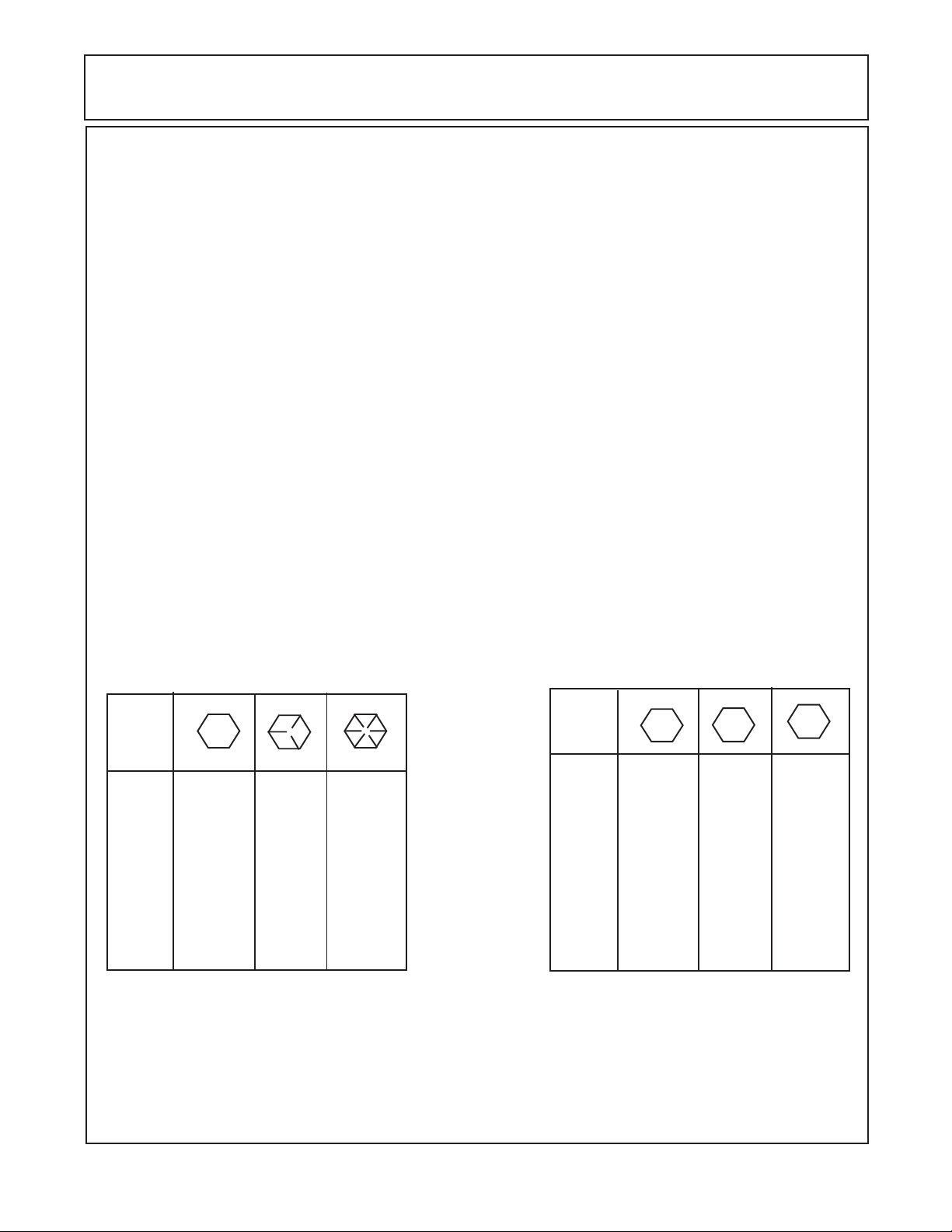
TORQUE VALUES - BOLTS:
Maximum Torque per Bolt Size and Grade, Ft lbs & (Nm)
IMPORTANT ! Listed below IS BOLT TORQUE and NOT APPLICATION TORQUE, Component
Application Torque will vary dependimg on what is bolted down and the type material (Metal) that is
being bolted together. Thread condition and lubrication will vary Torque settings.
Bolt
Dia.
inch
1/4
5/16
3/8
7/16
1/2
9/16
5/8
3/4
7/8
1
1-1/8
1-1/4
Inche Sizes
2 (B)
Plain Head
Not Used
Not Used
Not Used
35 (47)
55 (75)
75 (102)
105 (142)
185 (251)
160 (217)
250 (339)
330 (447)
480 (651)
3 Dashes
85 (115)
130 (176)
170 (230)
300 (407)
445 (603)
670 (908)
910 (1234)
1250 (1695)
5 (D)
10 (14)
20 (27)
35 (47)
55 (75)
8 (F)
6 Dashes
14 (19)
30 (41)
50 (68)
80 (108)
120 (163)
175 (230)
240 (325)
425 (576)
685 (929)
1030 (1396)
1460 (1979)
2060 (2793)
ALWAYS
CHECK
MARKINGS
ON
TOP
OF
BOLT
HEAD
OR
OTHER
BOLT
DESCRIP-
TIONS
Bolt
Dia.
mm
6
8
10
12
14
16
18
20
22
24
27
30
33
36
Metric Sizes
4.8
5
11
20
37
60
92
118
160
215
285
450
600
800
900
8.8
7
20
40
70
100
155
216
270
330
500
875
1200
1600
2100
10.8
12
25
58
105
140
200
280
355
430
700
1000
1700
2300
3000
HYDRO 15 (Service Manual) 09/06
© 2006 Alamo Industrial
Section 1 - 5
Page 14
SPECIFICATIONS - HYDRO 15 FLEX WING
8
8
8
8
8
8
8
8
8
8
8
8
8
8
8
8
8
8
8
8
8
8
8
1
1
1
1
1
1
1
1
1
1
1
1
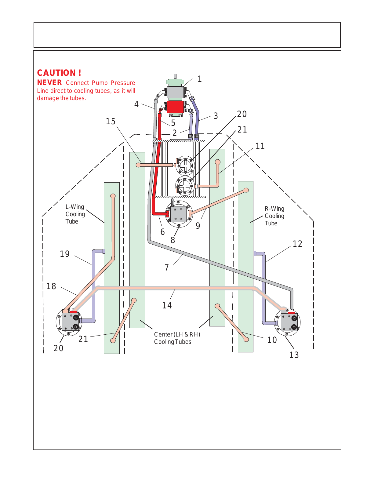
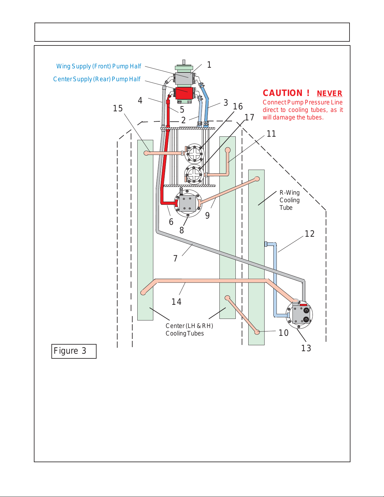
15 FT - PUMP & MOTOR HYDRAULIC SCHEMATIC
CAUTION !
NEVER Connect Pump Pressure
Line direct to cooling tubes, as it will
damage the tubes.
15
L-Wing
Cooling
Tube
19
1
4
3
20
5
2
2345678901234567
2345678901234567
2345678901234567
2345678901234567
2345678901234567
2345678901234567
2345678901234567
2345678901234567
2345678901234567
2345678901234567
2345678901234567
2345678901234567
2345678901234567
2345678901234567
2345678901234567
2345678901234567
2345678901234567
2345678901234567
2345678901234567
2345678901234567
2345678901234567
2345678901234567
2345678901234567
9
21
11
R-Wing
Cooling
Tube
6
8
12
7
18
14
21
Center (LH & RH)
Cooling Tubes
10
20
Item Description
1 Tandem Pump Asy
2 Suction (Tank to Wing Pump)
3 Suction (Tank to Center Pump)
4 Pressure (Pump to Bulk Head Fitting)
5 Pressure (Pump to Bulk Head Fitting)
6 Pressure (Bulk Head Fititng to Center Motor)
7 Pressure (Bulk Head Fitting to Wing Motors)
8 Motor Asy (Center Sction Motor)
9 Return (Center Motor to Wing CoolingTube)
1 0 Return (Wing Tube to Center Cooling Tube)
1 1 Return (Center Coolingg Tube to Fiter / Tank)
HYDRO 15 (Service Manual) 09/06
© 2006 Alamo Industrial
Item Description
1 2 Case Drain (R- Wing Motor to Cooling Tube)
1 3 Wing Motor Asy (R- Wing)
1 4 Return / Pressure (f/ R-Wing to L-Wing Motor)
1 5 Return (Center Cooling Tube to Filter / Tank)
1 6 Return Filter & Gauge (Wing Motors Return)
1 7 Return Filter & Gauge (Center Motor Return)
1 8 Return (L-Wing Motor to Cooling Tube)
1 9 Case Drain (L-Wing Motor to Cooling Tube)
2 0 Wing Motor Asy (L-Wing)
21 Return (L-Wing Tube to Center Cooling Tube)
Section 1 - 6
13
Page 15
SPECIFICATIONS - HYDRO 15 FLEX WING
8
8
8
8
8
8
8
8
8
8
8
8
8
8
8
8
8
8
8
8
8
8
1234567890123456789012345
1
1
1
1
1
1
1
1
1
1
1
1
1
1
1
12
12
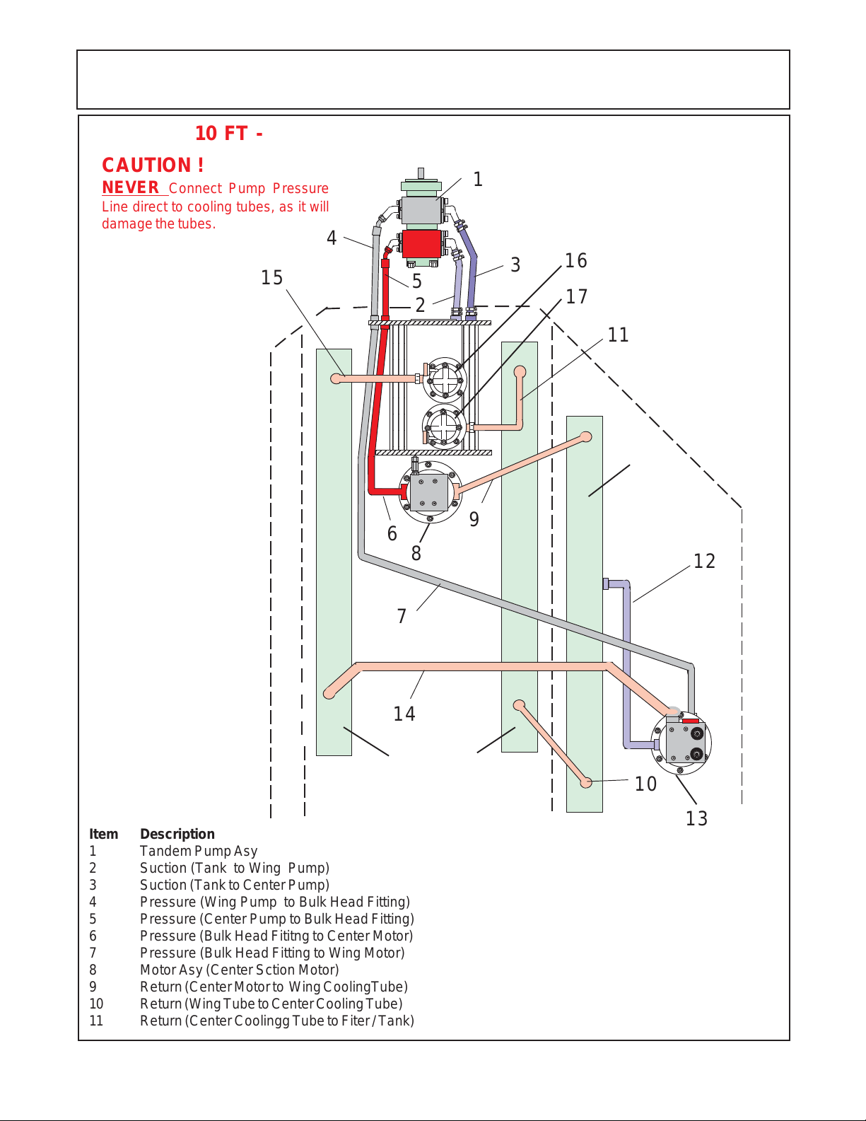
10 FT - PUMP & MOTOR HYDRAULIC SCHEMATIC
CAUTION !
NEVER Connect Pump Pressure
Line direct to cooling tubes, as it will
damage the tubes.
15
1
4
3
16
5
2
2345678901234567
2345678901234567
2345678901234567
2345678901234567
2345678901234567
2345678901234567
2345678901234567
2345678901234567
2345678901234567
2345678901234567
2345678901234567
2345678901234567
2345678901234567
2345678901234567
2345678901234567
2345678901234567
2345678901234567
2345678901234567
2345678901234567
2345678901234567
2345678901234567
2345678901234567
17
11
R-Wing
Cooling
Tube
9
6
8
12
Item Description
1 Tandem Pump Asy
2 Suction (Tank to Wing Pump)
3 Suction (Tank to Center Pump)
4 Pressure (Wing Pump to Bulk Head Fitting)
5 Pressure (Center Pump to Bulk Head Fitting)
6 Pressure (Bulk Head Fititng to Center Motor)
7 Pressure (Bulk Head Fitting to Wing Motor)
8 Motor Asy (Center Sction Motor)
9 Return (Center Motor to Wing CoolingTube)
1 0 Return (Wing Tube to Center Cooling Tube)
1 1 Return (Center Coolingg Tube to Fiter / Tank)
HYDRO 15 (Service Manual) 09/06
© 2006 Alamo Industrial
7
14
Center (LH & RH)
Cooling Tubes
Item Description
1 2 Case Drain (R- Wing Motor to Cooling Tube)
1 3 Wing Motor Asy (R- Wing)
1 4 Return (R-Wing Motor to Cooling Tube)
1 5 Return (Center Cooling Tube to Filter / Tank)
1 6 Return Filter & Gauge (Wing Motor Return)
1 7 Return Filter & Gauge (Center Motor Return)
Section 1 - 7
10
13
Page 16

NOTES
HYDRO 15 (Service Manual) 09/06
© 2006 Alamo Industrial
Section 1 - 8
Page 17

Section 2
HYDRO 15
Service & Repair
HYDRO 15 (Service Manual) 09/06
© 2006 Alamo Industrial
Pump
Section 2 - 1
Page 18

PUMP SERVICE & REPAIR
Recommended Reading Before any Service Work Begins:
1. Read this section completely before starting inspection or repair to the mower hydraulic system to become
familiar with its components.
2. Identify the model of the mower model number, serial number and other information that may be needed
to identify which components or options that may be on the mower.
3. Make certain the mower and tractor are secured in a safe and proper parked position, hydraulic (axle and
wings) lowered. Tractor safely parked according to tractor manufacturers recommendations.
4. Clean the complete hydraulic system in the area of the repairs. Dirt is the enemy of all hydraulic systems
and all steps must be taken to keep hydraulic system from being contaminated.
5. Make certain the hydraulic oil is not hot from being operated or tested. All hydraulic components (including
hydraulic oil) temperature should not exceed ambient temperatures. If temperature is high it must be allowed top
cool before attempting any repairs of the hydraulic system. Caution should be taken, if mower is sitting in hot
sun on a very hot day the temperature of the metal and oil can be hot, test the temperature.
6. The drawing and illustrations in this section are to help understand the components of the pump. This section
is not intended to be a parts manual or operators manual although it is intended to be used with the other manuals.
7. Use caution if clamping any pump components in a vise or gripping them with any type of tools. The
jaws of a vise can damage the surface or it the shape of a component, tools can scratch or damage the surface
to render the component un-serviceable
8. These pumps are designed to be assembled to be turned in the direction for which they were built, clockwise
or counter clockwise. When the pump is dis-assembled it is very important that you take notice of which
components are where and which way they are installed in pump (example Item 5). If these pumps are installed
with component in the wrong place and then turned in the wrong direction the pressure will usually blow the input
seal out and may damage other components.
9. When making repairs always make certain that the cause of the failure is identified and repaired. Sometimes
the cause of the failure is not corrected and another failure occurs rapidly because the cause of the failure is still
there.
10. Make certain to use drain pans to catch all oil that may leak out during the testing and/or repair steps. Make
certain to keep all hydraulic opening plugged or capped during repairs.
11. Never start the tractor and engage PTO to turn pump, if any hydraulic components have been removed or
disconnected, line blockage or oil diverted to the wrong place could to extreme damage to the hydraulic system
and/or to the mower deck cooling tubes.
12. The pressure side of the pump hydraulic flow MUST NEVER be sent directly to the deck cooling tubes as
the excess pressure will damage them. The hydraulic oil flow can only be sent through the deck cooling tubes
when it is being returned to the tank with little or no resistance.
13. Some components of hydraulic system are not meant the be repaired, only replaced. Do Not dis-assemble
a component if it is a part intended for replacement only.
14. When storing a pump or its components for any reason it is recommended they be stored in a clean area
and covered to protect from any dust, components that have been washed be coated which oil if they are made
of material that may rust.
HYDRO 15 (Service Manual) 09/06
© 2006 Alamo Industrial
Section 2 - 2
Page 19

PUMP SERVICE & REPAIR
Recommended To Test Old Hydraulic Pump before it is Removed:
(Before Installing a New or Rebuilt Pump).
A. Connect your Flow Meter in Line to test Pressure as unit is started; this is in case the Relief Valve is
malfunctioning or has been tampered with. If this is not done you could damage the replacement Pump
because you would not Know it until Pump failed from excessive pressure.
B. Before connecting any lines to Pump, fill all Ports with clean Oil to provide initial Lubrication. This is
especially important is Pump is located at a higher level than Oil Reservoir.
C. Check Oil level in reservoir, fill to full level if needed, Reservoir must have more Oil than the Pump GPM
capacity.
D. After connecting the Lines and mounting the replacement Pump, make sure that Oil is not warmer than
Pump temperature. If Oil is warmer than pump run Pump at short intervals till Pump and Oil temperature
is equalized. Hot Oil must not be fed into cold Pump.
E. Operate the Pump for at least two minutes at no load and at low RPM (400 RPM min and 1400 RPM max.).
Watch Flow Meter Pressure (or Pressure Gauge). During this break-in period, the unit should run free and
not develop an excessive amount of heat. Heat should not exceed 100 deg F. above ambient Temperature.
If the unit operates properly, speed and pressure can then be increased to normal operating settings.
Increase Pressure in 500 Lbs. PSI increments from start, this should take 4 to 5 minutes to max. PSI
allowing 1 minute between increases to check Oil Pressure and Temperature.
F. If normal Pressure and Heat readings are seen then the New or Rebuilt Pump installation should be done,
remove Flow Meter (Pressure Gauge) from line, reconnect Line and check all connections.
Test Equipment Needed:
1. Flow Meter, The Flow meter should have components to measure:
A. Guage to Measure the Oil Temperature.
B. Gauge to Measure Oil Pressure PSI (Load and No Load).
C. Gauge to Measure Oil Flow in G.P.M.
D. A Valve to load system to check operating Pressure (PSI).
E. Assortment of Connections to connect to Hydraulic System.
2. Electrical Volt Meter with variable settings and Ohm Meter.
3. Electrical Test Light.
4. Wrenches, (Socket Wrenches, Open and Boxed End Wrenches).
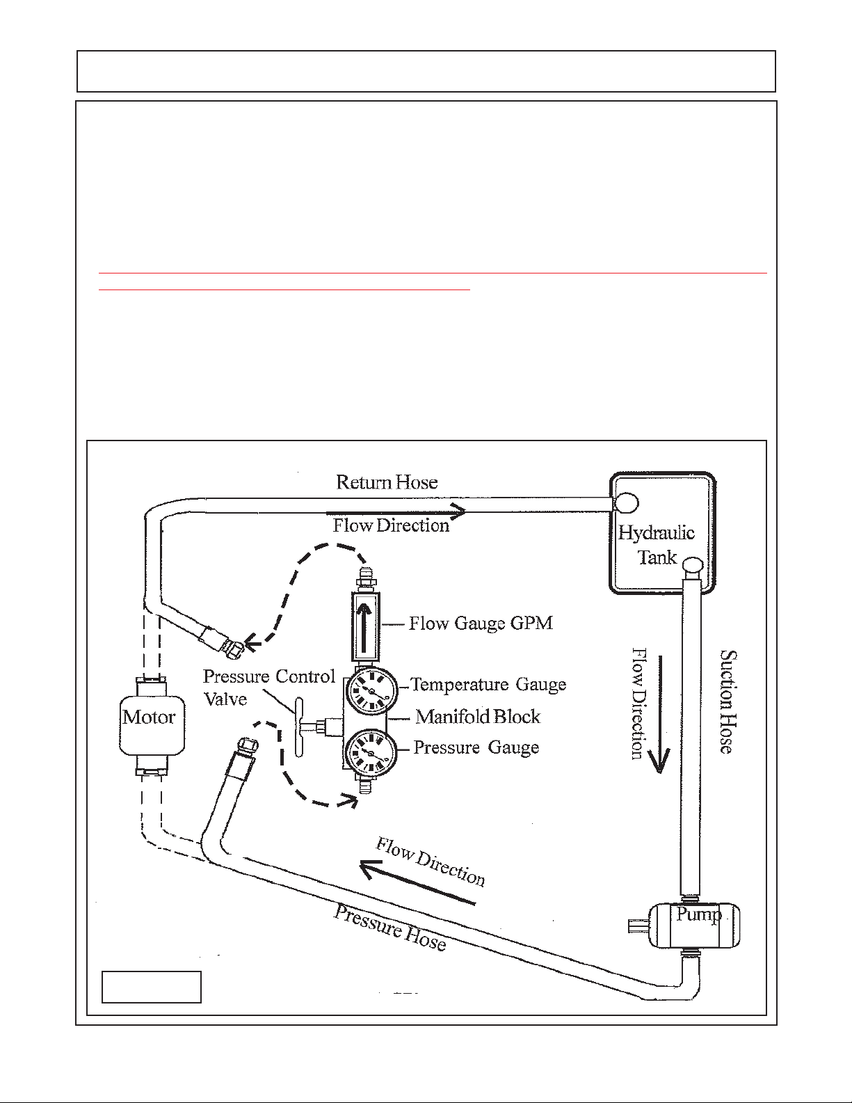
Flow Testing the Pump: (figure 1)
1. Use a Flow Meter that is rated to 6000 PSI and 60 GPM Minimum. This applies to the gear type pump
and motor type only
2. the area around the hoses, motor, flow meter must be clean of all debris and dirt. NO contamination can
be allowed to enter the system or its components. Make certain there is nothing in flow meter from
previous use that will contaminate the hydraulic system, dirty and contamination in test equipment
hoses and valves can cause a failure to occur.
3. Disconnect the hydraulic return hose from the motor. Connect the hoses to the flow meter as shown
above, recheck all connections to make certain they are connected correctly and fittings have been
check for tightness.
4. Completely open the pressure valve on the flow meter.
HYDRO 15 (Service Manual) 09/06
© 2006 Alamo Industrial
Section 2 - 3
Page 20
PUMP SERVICE & REPAIR
5. Record all the readings during the test. Start the system, run at 540 PTO speed (which will run pump at
required speed) until the Oil temperature reaches at least 110° F. before starting test. Check the flow (GPM)
at 0 psi. (or no load). Slowly close the pressure control valve (valve on flow meter) until the gauge pressure
reaches 500 psi. and record the readings pressure, temperature and flow (GPM). Continues this at 500 psi
increments until a maximum of 2000 psi.
6. If the flow rate is 85 % or greater of beginning flow rate at no load, the pump is serviceable and functioning
within specifications.
CAUTION ! Stop tractor engine and discontinue testing if hydraoulic oil temperature exceeds 220° F. as
temperatures above this could cause damage to components.
Example: Recorded test results
PSI. GPM TEMP ° F. PSI. GPM TEMP ° F.
0 ____ ________ 500 ____ ________
1000 ____ ________ 1500 ____ ________
2000 ____ ________ 2500 ____ ________
3000 ____ ________
Shown Below is a Gear Pump Schematic
Figure 1
HYDRO 15 (Service Manual) 09/06
© 2006 Alamo Industrial
Section 2 - 4
Page 21
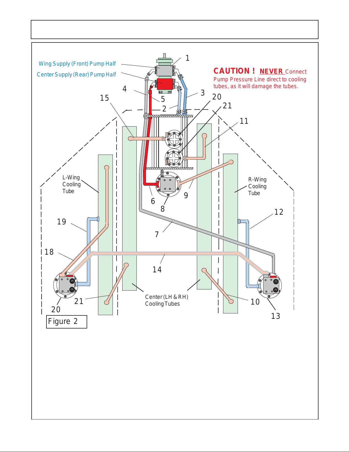
15 FT - PUMP & MOTOR HYDRAULIC SCHEMATIC
7
7
7
7
7
7
7
7
7
7
7
7
7
7
7
7
7
7
7
7
7
7
7
12
12
Wing Supply (Front) Pump Half
Center Supply (Rear) Pump Half
15
PUMP SERVICE & REPAIR
1
CAUTION ! NEVER Connect
Pump Pressure Line direct to cooling
4
5
2
234567890123456
234567890123456
234567890123456
234567890123456
234567890123456
234567890123456
234567890123456
234567890123456
234567890123456
234567890123456
234567890123456
234567890123456
234567890123456
234567890123456
234567890123456
234567890123456
234567890123456
234567890123456
234567890123456
234567890123456
234567890123456
234567890123456
234567890123456
tubes, as it will damage the tubes.
3
20
21
11
L-Wing
Cooling
Tube
9
R-Wing
Cooling
Tube
6
8
12
19
7
18
14
21
Center (LH & RH)
Cooling Tubes
10
20
13
Figure 2
Item Description
1 Tandem Pump Asy
2 Suction (Tank to Wing Pump)
3 Suction (Tank to Center Pump)
4 Pressure (Pump to Bulk Head Fitting)
5 Pressure (Pump to Bulk Head Fitting)
6 Pressure (Bulk Head Fititng to Center Motor)
7 Pressure (Bulk Head Fitting to Wing Motors)
8 Motor Asy (Center Sction Motor)
9 Return (Center Motor to Wing CoolingTube)
1 0 Return (Wing Tube to Center Cooling Tube)
1 1 Return (Center Coolingg Tube to Fiter / Tank)
HYDRO 15 (Service Manual) 09/06
© 2006 Alamo Industrial
Item Description
1 2 Case Drain (R- Wing Motor to Cooling Tube)
1 3 Wing Motor Asy (R- Wing)
1 4 Return / Pressure (f/ R-Wing to L-Wing Motor)
1 5 Return (Center Cooling Tube to Filter / Tank)
1 6 Return Filter & Gauge (Wing Motors Return)
1 7 Return Filter & Gauge (Center Motor Return)
1 8 Return (L-Wing Motor to Cooling Tube)
1 9 Case Drain (L-Wing Motor to Cooling Tube)
2 0 Wing Motor Asy (L-Wing)
21 Return (L-Wing Tube to Center Cooling Tube)
Section 2 - 5
Page 22
PUMP SERVICE & REPAIR
7
7
7
7
7
7
7
7
7
7
7
7
7
7
7
7
7
7
7
7
7
7
12
12
10 FT - PUMP & MOTOR HYDRAULIC SCHEMATIC
Wing Supply (Front) Pump Half
Center Supply (Rear) Pump Half
15
1
CAUTION ! NEVER
4
5
3
16
2
234567890123456
234567890123456
234567890123456
234567890123456
234567890123456
234567890123456
234567890123456
234567890123456
234567890123456
234567890123456
234567890123456
234567890123456
234567890123456
234567890123456
234567890123456
234567890123456
234567890123456
234567890123456
234567890123456
234567890123456
234567890123456
234567890123456
Connect Pump Pressure Line
direct to cooling tubes, as it
will damage the tubes.
17
11
R-Wing
Cooling
Tube
9
6
8
12
7
14
Center (LH & RH)
Cooling Tubes
Figure 3
Item Description
1 Tandem Pump Asy
2 Suction (Tank to Wing Pump)
3 Suction (Tank to Center Pump)
4 Pressure (Wing Pump to Bulk Head Fitting)
5 Pressure (Center Pump to Bulk Head Fitting)
6 Pressure (Bulk Head Fititng to Center Motor)
7 Pressure (Bulk Head Fitting to Wing Motor)
8 Motor Asy (Center Sction Motor)
9 Return (Center Motor to Wing CoolingTube)
1 0 Return (Wing Tube to Center Cooling Tube)
1 1 Return (Center Coolingg Tube to Fiter / Tank)
HYDRO 15 (Service Manual) 09/06
© 2006 Alamo Industrial
Item Description
1 2 Case Drain (R- Wing Motor to Cooling Tube)
1 3 Wing Motor Asy (R- Wing)
1 4 Return (R-Wing Motor to Cooling Tube)
1 5 Return (Center Cooling Tube to Filter / Tank)
1 6 Return Filter & Gauge (Wing Motor Return)
1 7 Return Filter & Gauge (Center Motor Return)
Section 2 - 6
10
13
Page 23
PUMP SERVICE & REPAIR
Recommended Tools:
Listed below are some of the toolds that
are recommended for the dis-assembly and reassembly of the pump for the HYDRO 15 Mower.
1. Arbor Press
2. Awl
3. 1-1/2" Dia steel ball
4. Bearing Puller (Owaonna Tool Co.
MD-956 or equivalent)
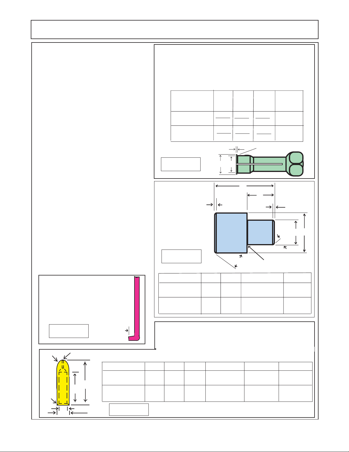
5. Bushing Remover Tool (figure 4)
6. Clean lintless Cloth
7. Deburing Tool (an old file with cutting
teeth ground off)
8. Machinest Hammer
9. Soft Hammer
10. Permatex Aviation Form-A-Gasket.™
(No. 3 non hardening sealant or equal)
11. Medium Grit Carborundurn Stone.
12. Seal removal Tool (figure 6)
13. Oil and Grease
14. Snap Ring Pliers
15. Prick Punch
16. Bushing Installation Tool (figure 5).
17. Scale (1/32" or 1/64" graduations)
18. Small Screw Driver
19. Torque Wrench (in. lbs & ft lbs)
20. Vise with 6" minimum opening
21. Bar for Lip Seal Installation
For Front (Wing Supply) Pump
use 1-3/4" dia X 2" Bar
For Rear (Center Supply) Pump
use 2-1/2" dia X 2" Bar
22. Special Steel Sleeve (figure 7)
Seal Removal Tool: Easily
made from old screw driver.
Heat the tip and bend as
shown. Grind the tip to fit the
notch behind the shaft seal.
Bushing Puller: The bushings in the pump may be
removed from tier bores, using blind hole collet-type bushing
pullers similar to those manufactured by Owatonna Tool Co. The
Table below illustrates the modification necessary to adapt the
OTC collets to this task. Equivalent pullers from other suppliers
may be modified in a similar fashion.
Pump
Wing Supply
Pump
Center Supply
Pump
Figure 4
Bushing Installation
Tool A.I.S.I 8620
Bearing Qaulity
Steel Heat treated
AB C
.980
.970
1.382
1.372
C
AB
.06
.875
Ref
1.260
1.250
.100
.090
.100
.120
.015 R Maximum
A
B
.06
Make
f/ OTC
Collet No.
33863
33865
Surface
Finish
32
C D
30°
Figure 5
Pump
Wing Supply
Pump
Center Supply
Pump
A
3.00
3.00
30°
B
1.47
1.73
Grind Relief Allowable
C dia.
1.492
+ .000
- .002
+ .000
- .002
1.054
D dia.
1.250
1.750
Figure 6
C Rad
F°
HYDRO 15 (Service Manual) 09/06
© 2006 Alamo Industrial
1/4" Hole Drill through
Wing Supply
B
A
E
D
Center Supply
1/4"
Pump A
Pump
Pump
3-3/8"
3-3/8"
Figure 7
Special Steel Sleeve: The special steel sleeve is used to insert the
drive shaft through the lip seal without damage and can be made
from bar stock. For the center supply pump use a 1-1/8" to 1-1/4"
dia X 4-5/8" bar. For wing supply pump use a 1-1/2" dia X 4-5/8" bar.
The drawing and cgart give details for making this special tool.
B C Rad
4-1/2" 1.065 .015" X 45°
4-1/2"
All external surfaces MUST be free of scratches and burrs
9/16"
9/16"
D Rad E dia.
+ .000
- .002
+ .000
1.377
- .002
1.002
1.250
+ .002
- .000
+ .002
- .000
F° Chamfer
.015" X 60°
Section 2 - 7
Page 24
PUMP SERVICE & REPAIR
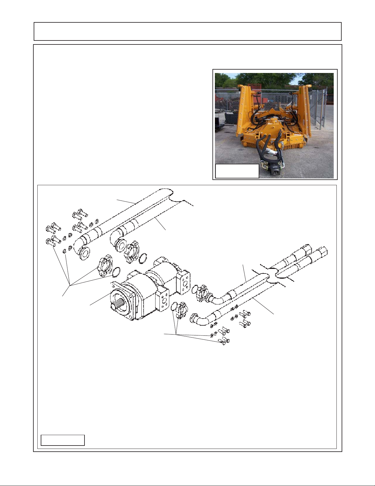
Pump Cleaning & Removal:
1. Clean Pump, Hoses and all connections before disconnecting any components from the pump. This will keep contamination from getting into system. Figure 8 shows the pump
and hoses connected to the mower (this mower is new, clean
and un-used) with the pump sitting on the ground, if the hoses
are to be dis-connected, the pump should mounted up and
above the hydraulic tank (on work bench, hoist, etc.). What
ever the technician decides to mount pump on. Some type of
drain pan will be required to catch the oil that will drain out when
hoses are dis-connected. The hoses will need to be capped
(plugged) after removal being disconnected. If cap is not leak
proof then hoses must remain elevated above hydraulic tank to
prevent oil leakage from hose fittings. Figure 9 shows how the
hoses are connected. Hoses are connected with 4 bolt split
flange kits (1-1/2" on suction side &1" on pressure side)
7
Figure 8
Tandem Mounted Pump
3
Figure 9
6
5
1
4
2
Item Qty Description
1 1 Pump Assembly (Tandem Pump)
2 2 Split Flance Kit, (1" Flange)
1 O-Ring (for 1" Flange) (Qty Each Kit)
4 Bolt, Hex Head, (Qty Each Kit)
4 Lockwasher (Qty Each Kit)
3 2 Split Flance Kit, (1-1/2" Flange)
1 O-Ring (for 1" Flange) (Qty Each Kit)
4 Bolt, Hex Head, (Qty Each Kit)
4 Lockwasher (Qty Each Kit)
4 1 Hose Asy, 1" Hose & Flange (Pressure to Wing Motors)
5 1 Hose Asy, 1" Hose & Flange (Pressure to Center Motor)
6 1 Hose Asy, 1-1/2" Hose & Flange. (Suction Hose for Center Motor
7 1 Hose Asy, 1-1/2" Hose & Flange. (Suction Hose for Wing Motor)
HYDRO 15 (Service Manual) 09/06
© 2006 Alamo Industrial
Section 2 - 8
Page 25
PUMP SERVICE & REPAIR
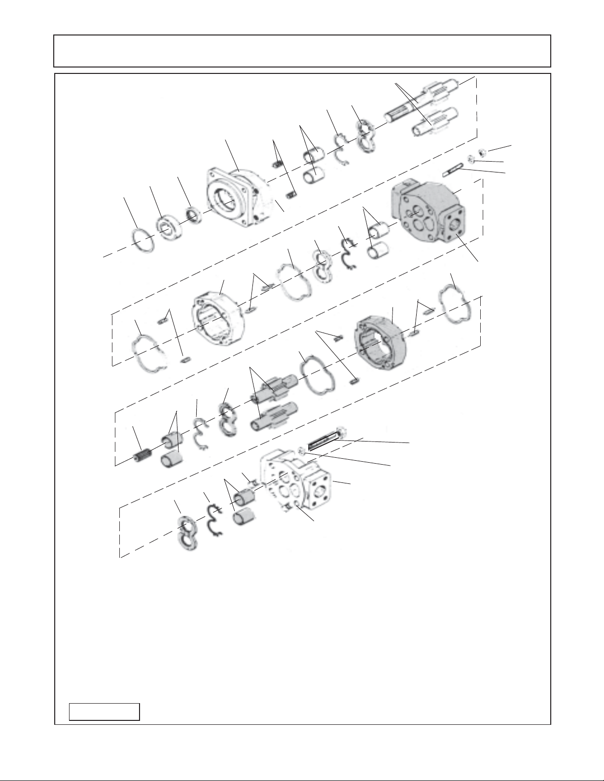
Pump Component Schematic
4
2
3
1
12
11
10
8
7
6
15
11
8
7
6
5
9
Item 5 install this side (outlet side)
6
7
8
10
16
11
10
11
10
20
19
18
13
14
5
6
7
8
Item Qty Description
1 1 Snap Ring
2 1 Bearing, Outboard
3 1 Seal, Input
4 1 Shaft End Cover
5 1 Plug
6 8 Bushings
7 4 Channel Seal
8 4 Thrust Plate
9 1 Integral Drive Shaft and Gear Set
1 0 4 Gasket Seal
Figure 10
22
21
17
Item 5 install this side (outlet side)
Item Qty Description
11 8 Dowel Pins
12 1 Gear Housing
13 1 Bearing Carrier
14 1 Connecting Shaft
1 5 1 Gear Set (Matched)
16 1 Gear Housing
17 1 Port End Cover
18 4 Studs
19 4 Lockwasher
20 4 Nuts
21 4 Lockwasher
22 4 Bolt
HYDRO 15 (Service Manual) 09/06
© 2006 Alamo Industrial
Section 2 - 9
Page 26
PUMP SERVICE & REPAIR
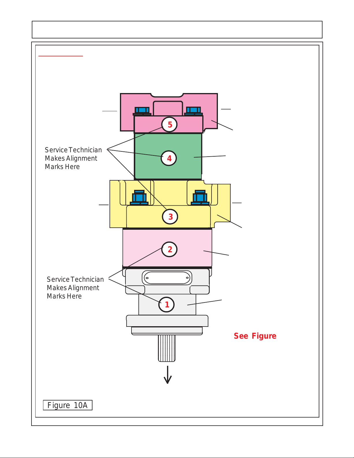
IMPORTANT !
Mark all Sections of Pump with a Number (or) Symbols that will serve as a guide to all sections
being re-installed the same way they were removed. Example: if the numbers (marks) do not line up
(1, 2, 3, 4 & 5) as they were marked, the pump is not being assembled correctly. Check this all through
the assembly process.
1-1/2" Split Flange
Suction (Inlet) Side
Service Technician
Makes Alignment
Marks Here
1-1/2" Split Flange
Suction (Inlet) Side
1" Split Flange
Pressure (outlet) Side
5
Port End Cover
Rear Gear Housing
4
1" Split Flange
Pressure (outlet) Side
3
Port Bearing Housing
2
Front Gear Housing
Service Technician
Makes Alignment
Marks Here
Figure 10A
HYDRO 15 (Service Manual) 09/06
© 2006 Alamo Industrial
1
Speed Changer
&
Tractor PTO
Section 2 - 10
Shaft End Cover
See Figure 10
for Compo-
nent Item
Number
Page 27
PUMP SERVICE & REPAIR
Pump Dis-Assembly CAUTION! :
Important information - read before dis-assembly:
1. If prying off sections becomes necessary, take extreme
care not to mar or damage machined surfaces. Excessive
force while prying can result in misalignment and seriously
damage parts.
2. If parts are difficult to come apart during dis-assembly,
tap gently with a soft hammer (never use an iron hammer).
3. Gears are closely matched, therefore they must be kept
together as sets when removed from the pump. Handle
gears with care to avoid damage to journals or teeth. Avoid
touching gear journals.
4. Never hammer bushing into bores: always use an arbor
press.
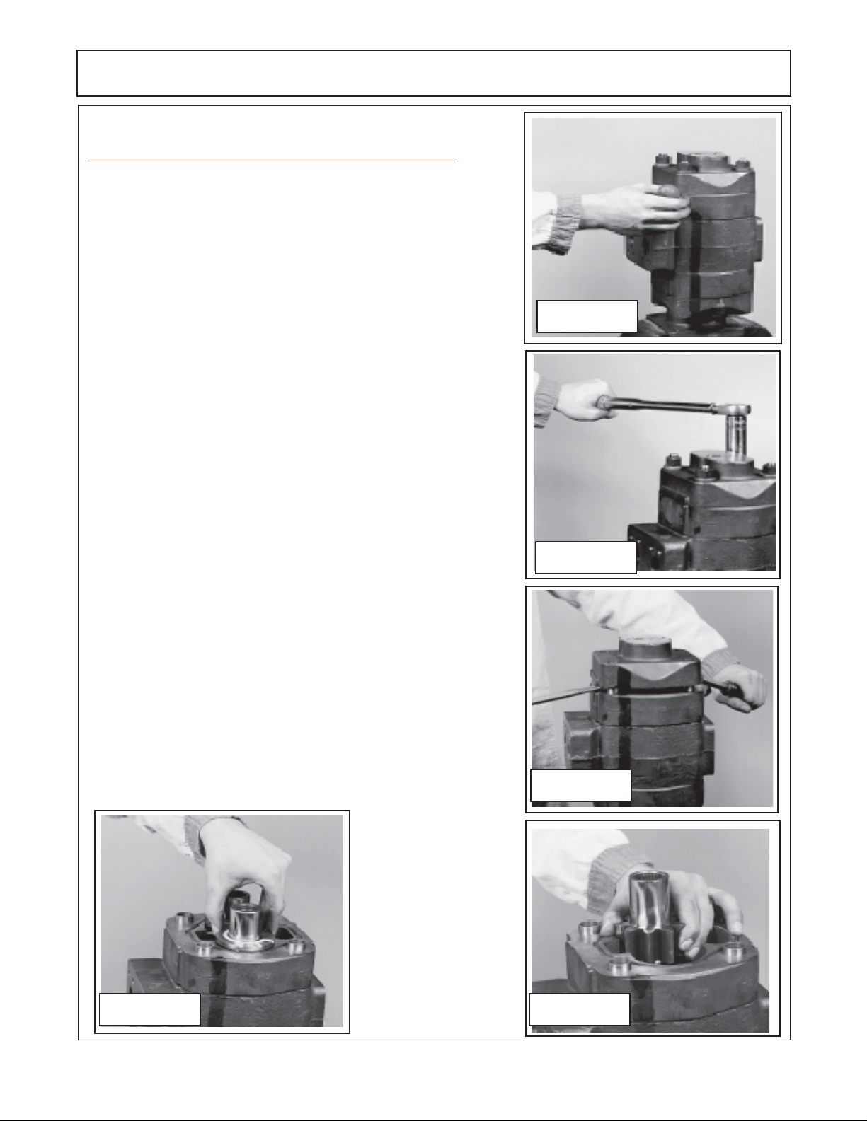
Pump Dis-Assembly:
1. Place the pump in a vise with the drive shaft pointing down.
Caution DO NOT grip on or near any machined surfaces of pump
during assembly or dis-assembly. Mark all sections of the pump
(figure 10A) , these marks must be done in a manner that will not
wash off and these marks are to identify the orientation of the
component of the pump later for re-assembly. It is recommended
that marks be done with metal stamps that will mark components
for correct assembly order for & during re-assembly. This is very
important as if any of the sections of pump are installed in the
wrong direction it could damage pump when re-assembled or when
pump is engaged during operation (figure 11).
Figure 11
Figure 12
2. Use a socket Wrench or Boxed end wrenches (Air impact
wrenches are not recommended for dis-assembly). Remove the
four hex bolts and washers (figure 10 item 19 & 20) , This will allow
for the removal of the outward half of the pump. The inward section
is still connected together with the studs and nuts which will be
removed in a later step. Inspect the bolts for thread condition. If
bad threads on bolts most likely the threads in that hole are bad,
mark the hole so it can be check later.
Figure 14
HYDRO 15 (Service Manual) 09/06
Figure 13
Figure 15
© 2006 Alamo Industrial
Section 2 - 11
Page 28
PUMP SERVICE & REPAIR
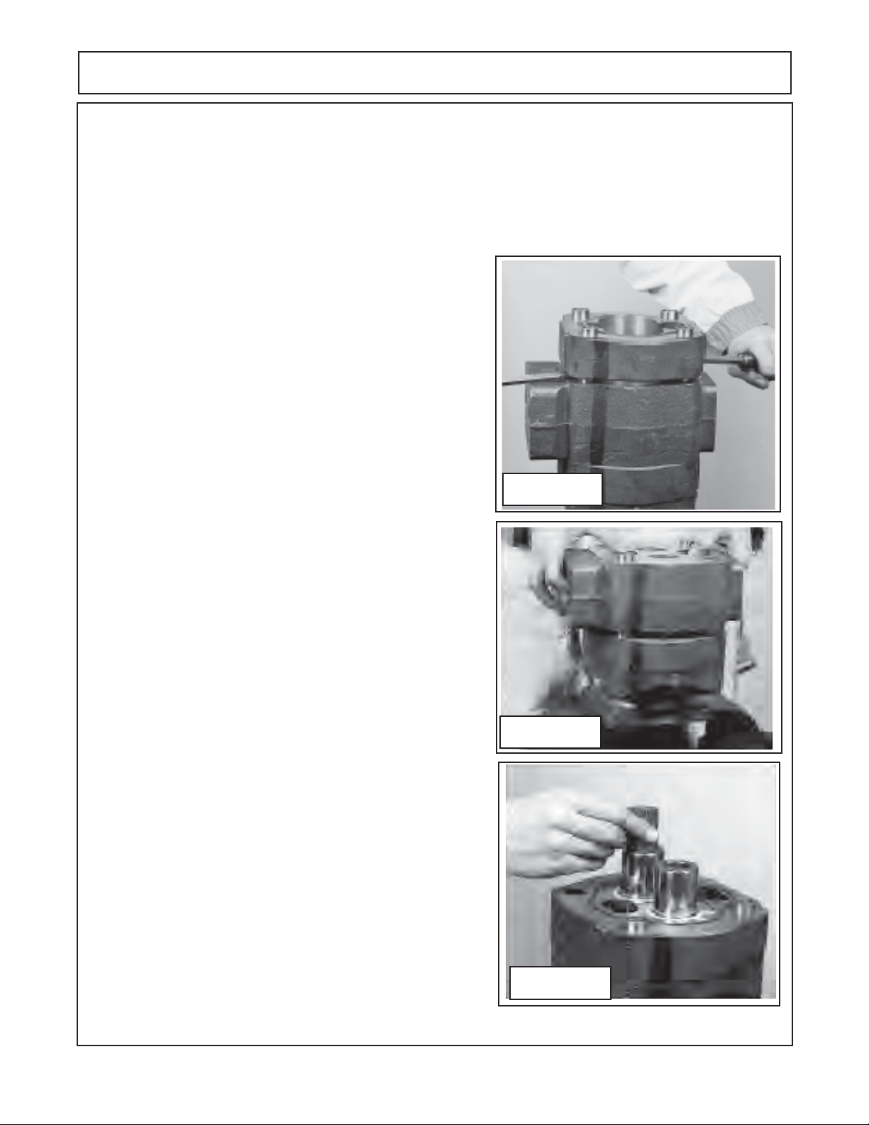
3. Lift the first port end cover (figure 10 item 17), if prying is necessary, be careful not to damage the machined
surfaces. Dowel pins (figure 10 item 11) will remain in either the port end cover or gear housing. This will be
OK because the components must be re-assembled in the same direction and orientation as removed. If one
or more of the components are to be replaced as parts then it may require that the dowel pins be removed
(figure 13).
4. Remove the thrust plate (figure 10 item 8). Make a note how this was removed, there is a smooth side and
there is a grooved side. The smooth side will always face the gears, the grooved side will be for the channel
seal (figure 10 item 7). Inspect the thrust plate for damage or
wear at this time (see wear tolerance chart for pump and motors
in this section), this will help in looking for other wear or damage
to other components and also enable you to start making a list
of components that need replacing.
5. Carefully remove the drive gear and the driven gear (figure 10
item 15). Avoid tapping the gear teeth together or against other
hardened surfaces (figure 15), Keep these gears together
because they are a matched set. Examine the gears for wear
and/or damage. Note the dowels (figure 15) that are in the gear
housing, sometimes these will come out and be in the end cover
or they may stay in the gear housing. It will be OK as long as
the same components are to be reassembled, but if some
components are to be replaced and some are not then these
dowel pins will have to be re-moved and re-inserted.
Figure 16
6. Remove the outer gear housing (figure 10 item 16). Lift the
outer gear housing (figure 16) up, if prying is necessary take
care not to damage machined surface. Examine gear housing
for wear and /or damage. (See wear tolerance chart for pump
and motors in this section). When the gear housing is removed
there will be another thrust plate and channel seal (figure 10
item 7 & 8) that was under the gears, sometimes this thrust
plate will come out with the gears.
7. Carefully lift or pry the bearing carrier (figure 10 item 13)
off carefully to avoid damage to carrier (figure 17). The dowel
pins will remain in the bearing carrier housing or the gear
housing, it will not require that they be removed unless the
housing is to be replaced and then only to arrange the dowel
pins order so the components will fit together.
8. Remove the connecting shaft (figure 10 item 14) as shown
(figure 18) by pulling it up out of the drive gear shaft splines.
Inspect the shaft for wear and /or damage. Inspect the end of
the drive gear. Remove the thrust plate, note the thrust plate
will have the channel seal in it (figure 10 item 7 & 8). Note the
smooth side of thrust plate always goes toward the gear. Care
fully remove the drive gear and the driven gear (figure 10 item 9).
Avoid tapping the gear teeth together or against other hardened
surfaces (figure 18), pull the drive gear straight up. The drive
gear has the splined shaft on the other end and care must be
taken not to hit the splined shaft against sides and damaging
them.Keep these gears together because they are a matched
set. Examine the gears for wear and / or damage
Figure 17
Figure 18
HYDRO 15 (Service Manual) 09/06
© 2006 Alamo Industrial
Section 2 - 12
Page 29
PUMP SERVICE & REPAIR
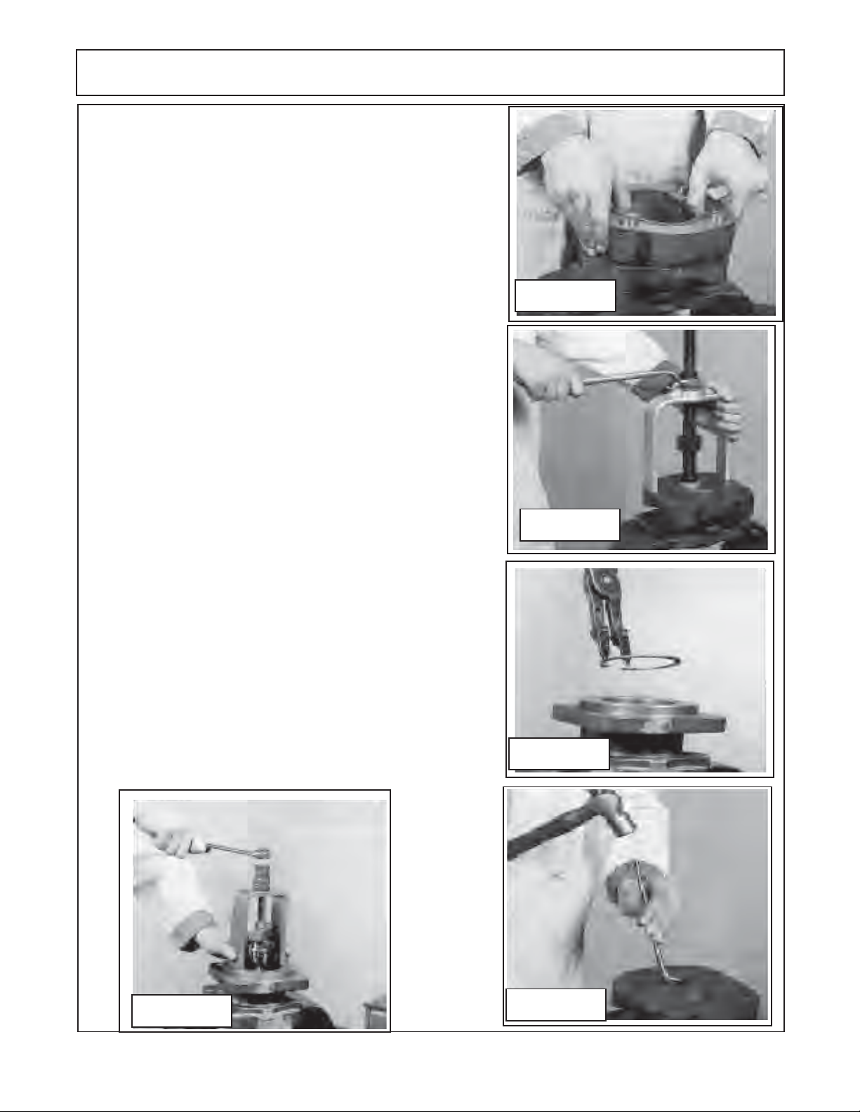
9. Lift or pry off the first section of gear housing (figure 10 item
12). Be careful not to damage machined surfaces (figure 19).
Inspect the gear housing (See wear tolerance chart for pump
and motors in this section). for wear and / or damage.
10. Inspect all of the bushings for scoring or discoloration (figure
10 item 6 qty 8) in the port end cap, bearing carrier (both sides)
and the shaft end cover. If they need to be replaced use a
bushing puller as shown (figure 4 recommended tools list).
Remove the bushings with care not to damage housings (figure
20).
11. Remove shaft end cover (figure 10 item 4) from vice and turn
it 180° over and re-insert it into vice. Using snap ring pliers
remove the snap ring (figure 10 item 1) as shown (figure 21).
12. Remove the shaft bearing (figure 10 item 2) using a bearing
puller (figure 22). Make certain to use the correct size bearing
puller and that puller is inserted straight.
Figure 19
13. Remove shaft end cover
it 180° over and re-insert it into vice. Remove the double lip seal
by inserting the special seal removal tool (see figure 6 recom-
mended tools). Make note of which way seal is removed. Inspect
the shaft end cover seal seat area (figure 23).
14. Inspect all the components that have been removed (review
steps 1 through 13). There are 4 gasket seals (figure 10 item 10)
that are installed, one on each side of the gear housing. Make
certain the gasket seal have been removed and the gasket
grooves are clean. Wash and clean all the components, DO NOT
use any material that will leave lint on components, it 's best to
air dry the components. Useextreme caution when cleaning
gear sets, DO NOT use any abrasive materials at all and DO
NOT bang the gears together. Keep the gears in the same sets
as they were remove as they are a matched set and must
remain as a set. (See next two pages for wear identification).
(figure 10 item 4) from vice and turn
Figure 20
Figure 21
Figure 22
HYDRO 15 (Service Manual) 09/06
© 2006 Alamo Industrial
Figure 23
Section 2 - 13
Page 30
PUMP SERVICE & REPAIR
Wear Tolerance for Pump & Motor:
This is suggested Wear Tolerance to Keep Assemblies operating as efficient as
possible, Not Complete failure rate. Your Pumps and/or motors may not be exact same as
discussed here.
Gear Housing: Gear type Pump and Motor
Gear Housing
Cut-Out Area
Gear Wear Area
Wear in excess of .007" cut-out necessitates replacement of the Gear
Housing. Place a straight edge across the Bore in the cut out area. If you can slip
a .007"feeler gage under the straight edge in the cutout area. Replace the Gear
Housing.
Pressure pushes the Gears against the Housing on the Low-Pressure side.
As the Hubs and Bushings wear, the cutout becomes more pronounced.
Excessive cutout wear in short period of time indicates excessive pressure or Oil
contamination. If the relief Valve Settings are within prescribed limits check for
shock pressures or tampering. Withdraw Oil Samples and check it and tank for
dirt. Where cut-out is moderate, 0.007" or less, gear housing is in good enough
condition and may be reused, understand if you are at 0.007" you are at the upper
limits and will not be at peak performance. A pump should always produce at least
85% efficiency (Example: if your Pump is rated at 37 GPM it should produce at
least 32 GPM).
Gear Teeth
Gear Hubs
Seal
Area
Gear Teeth
Splines
Thrust Plate
Gears:
Any scoring on Gear Hubs necessitates Replacement. Scoring, Grooving or
Burring of Outside diameter of Teeth requires replacement. Nicking, Grooving or
Fretting of Teeth surfaces also necessitates replacement.
Drive Shaft: (with Built on Gear)
If Gear Teeth and Gear Hubs are OK, Inspect Splines on input end (OD) of
Shaft and the Splines (ID) Output) Coupler End (Tandem Pump) for condition and
Wear.
Inspect Wear or damage to Seal Wear Area. If damage at Seal are check for
contamination. Note: Some Pumps and/or Motors may have Keyway or Splines.
Either will have to be inspected for condition. If Damage in any of these area the
Shaft / Gear will have to be replaced.
Thrust Plate:
The Thrust Plate Seals the Gear Section at the sides of the Gears. Wear will
allow internal slippage, which is Oil bypassing within the pump. The Pump and
Motor Thrust Plates are different even though they may look very similar. They are
built different. They will not interchange.
A Maximum of 0.002" wear is allowable. Replace Thrust Plates if they are
scored, eroded or pitted. Wear can be checked usually by comparing thickness
at outer edges with thickness at Gear contact area.
1. Check center of Thrust Plates where the Gears mesh. Erosion here indicates
Oil contamination.
2. Pitted Thrust Plates indicate cavitation or Oil aeration.
3. Discolored Thrust Plates indicate overheating, probably insufficient Oil.
HYDRO 15 (Service Manual) 09/06
© 2006 Alamo Industrial
Section 2 - 14
Page 31

PUMP SERVICE & REPAIR
IMPORTANT !
Mark all Sections of Pump with a Number (or) Symbols that will serve as a guide to all sections
being re-installed the same way they were removed. Example: if the numbers (marks) do not line up
(1, 2, 3, 4 & 5) as they were marked, the pump is not being assembled correctly. Check this all through
the assembly process.
1-1/2" Split Flange
Suction (Inlet) Side
Service Technician
Makes alignment
Marks Here
1-1/2" Split Flange
Suction (Inlet) Side
Bearing Housing Retaining Nuts & studs
(Torque to 3000 in lbs.
1" Split Flange
Pressure (outlet) Side
5
Port End Cover
Rear Gear Housing
4
1" Split Flange
Pressure (outlet) Side
3
Port Bearing Housing
2
Front Gear Housing
Service Technician
Makes Alignment
Marks Here
Figure 23A
HYDRO 15 (Service Manual) 09/06
© 2006 Alamo Industrial
1
Speed Changer
&
Tractor PTO
Section 2 - 15
Shaft End Cover
See Figure 10 for
Component Item
Number
KEEP THESE
MARKS ALIGNED
During Assembly
Page 32

PUMP SERVICE & REPAIR
Pump Assembly CAUTION! :
Important information - read before assembly:
1. All sections have been cleaned and inspected, take extreme care not to allow the marring or
damage to machined surfaces to occur. Make certain all components are laid out so as not to
damage the machined surfaces.
2. Make certain any replacement parts have been compared to the old parts to make certain they
are correct.
3. Gears are closely matched, there fore they must be kept together as sets when removed from
the pump. Handle gears with care to avoid damage to journals or teeth. Avoid touching gear journals.
DO NOT mix new and old gears when reassembling pump.
4. Never hammer bushing into bores: always use an arbor press, Hammering will damage
bushings and possibly the bores in the housing.
5. (NOTE illustrations shown here are for a single pump, the tandem
sections, the disassembly will be basically the same with the exception tandem pump has two
pump section instead of one. See figure 9 & 10 for reference to components).
pump is longer with more
Thrust Plate
Relief Groove (High
Pressure)
Gear Side
(Smooth Side)
Figure 24
Gear Housing
Inlet
(Suction)
Core
Opening
Channel
Seal Side
(Grooved Side)
Gear Bore
Thrust Plate
Installed in Gear
Housing
Relief Groove (High
Pressure)
Outlet
(pressure)
Core
Opening
Gasket Seal
Thrust Plate CAUTION! : (Figure 24)
Important information - read before assembly:
1. Thrust Plates must be in good condition, no scratches or excessive worn places on either side
of plate.
2. Thrust plates must be installed correctly, The thrust plate has two surfaces, one surface has
a groove for the channel seal and the other surface is smooth with a relief groove (notch) in it.
3. Thrust plate smooth surface with relief notch will always face the gears, the groove side for the
channel seal side will always face the gear bearing journal bushings never the gears as the gear
would destroy the channel seal.
4. The relief groove will face the High Pressure side or Outlet Side of the gear housing. This is
determined by the port (bearing carrier or port end cap) port size. The Inlet (suction Side port will
have a bigger opening than the pressure side.
5. These thrust plates are very important to the way they are installed. If they are installed wrong,
the pump will not function properly and other components could be damaged if operated with them
wrong.
HYDRO 15 (Service Manual) 09/06
© 2006 Alamo Industrial
Section 2 - 16
Page 33

PUMP SERVICE & REPAIR
Pump Assembly:
1. Check all the machined surfaces on all pump components to make certain they are level and free of
scratches. Minor scratches and slight un-level conditions may be fixed by using a Medium Grit Carborundurn
Stone. This must be done equal all the way across the face of the machine surface to keep it level (figure 25).
ALL part must be cleaned and dried if stone is used it. If deep scratches or excessively un-level the section
will need to be replaced, so make certain this is checked
before continuing installation of other components. Replace the parts with machined surfaces if required. Check
components for wear or damage now before continuing.
2. If the bushings (figure 10 item 6) were removed and new
ones need to be replaced. Inspect the holes where the
bushing will be pressed in. If there are burrs or rough edges
at the tops of the holes they can be de-burred by using your
finger and emory cloth. Keep the emory cloth on an angle
and only around the top of the bore (figure 26). Do this to each
hole for the bushing that are to be replaced. IMPORTANT !
Bushing must be pressed inwith an arbor press DO NOT
drive them in with a hammer.
3. Insert the shaft end cover in the vise with the machined
surface up (figure 27). Examine the plug in the surfaced area.
It is NOT required to remove this plug un-less the shaft end
housing is being replaced. This pump (PGP/PGM 365
Series) has one plug and it is installed on determines the
direction of travel of the pump, DO NOT change the location
of this plug un-less you want to change travel direction. If
plug is changed by error the pump will be damaged when
engaged, it will most likely blow the shaft seal out of it and
it may damage other components in the mowers hydraulic
system. This plugged is change by using a screw driver if
need be.
4. If new plugs are to be installed, coat the threads of the
plug with locktite™ thread sealant. If new plugs have been
installed, they need to be screwed in tightly. Stake the plug
with a prick punch at both ends of the screw drive slot and
around the edges. Peen the edge of the hole 1/32" to 1/16"
with a 1-1/2" dia steel ball (a 1-1/2" ball peen ball end of a
hammer can be used for this (figure 28), when striking ball
peen hammer flat end put a piece of cloth over it to prevent
chips from flying off of hammer . DO NOT use hammer direct
to hit plugs
Figure 25
Figure 26
5. Note: Steps 5, 6, 7 & 8 apply to Shaft End Cover (figure
10 item 4), Bearing Carrier (figure 10 item 13) and Port End
Cover (figure 10 item 17) Any bushing removed from the shaft
end cover, port end cover or bearing end cover should be
assembled in the drive bores with the grooves to the top of
unit (12 O'clock). Assemble the bushings in the driven bores
with the groove to the bottom of the unit (6 O'clock). The
Grooves refer to the bearing seam (figure 29).
HYDRO 15 (Service Manual) 09/06
© 2006 Alamo Industrial
Section 2 - 17
Figure 27
Page 34

PUMP SERVICE & REPAIR
6. Bushings should be pressed into the bores one at a time, Use the special installation tool (figure 5 Tools
recommended list) and an arbor pres. Be sure that the groove (or seam) are positioned as stated in step 5
previously. Be sure to support casting so they are square and level to the arbor press and the bushings are
straight before attempting to press them in. The bushing must be pressed into the bores flush with the casting
face (figure 30).
7. Repeat steps 1 and 2 after busings are installed (See
steps 1 & 2). Just as earlier if the stone is used parts it is used
on MUST be washed and dried . Make certain bushings are
flush with castings and there are NO burrs on the top ID of
bushings. (figure 31).
8. Check to make certain that the dowel pins are in place in
anynew castings and that the location corresponds with the
mating casting. Before inserting any dowel pins check to make
certain holes are clean, the top of the holes do not have burrs.
To insert dowels hold the dowel in alignment with the hole.
Gently start the pin into the hole straight, tap lightly with a soft
hammer until dowel is seated into hole. (figure 32). Note as
shown, dowel pins have holes in the center, this is for the
studs to go through.
Figure 28
9. Remove the shaft end cover from the vice and turn it over
180° and re-insert it into the vise with the splined side up (figure
34).Before inserting the new lip seal (figure 10 item 3) into the
shaft end cover Coat the outer edge of the lip seal with
Permatex Aviation Form-A- Gasket™ No. 3 non-hardening
sealant or equivalent. With the metal side of the seal up, press
it into the mounting flange side of the shaft end cover with an
arbor press and bar (see recommended tools list). Be careful
not to damage the lip seal. Press the lip seal in until flush with
the recess, wipe off excess sealant.
10. Install the outboard bearing (figure 10 item 2), guide the
bearing into the recess in the shaft end cover. This is a light
press fit and can be pressed in with the arbor press or it can
be lightly tapped into the bore. DO NOT use excessive force
to insert bearing, if it will not go with light (continued next page)
Figure 29
Figure 30
HYDRO 15 (Service Manual) 09/06
© 2006 Alamo Industrial
Figure 31
Section 2 - 18
Page 35

PUMP SERVICE & REPAIR
(continued from previous page) force check for size error or other
reason. Forcing an over size bearing in will damage bearing and
casting (figure 34).
11. Using the snap ring pliers as shown. Install the snap ring into the
flange side of the shaft end cover (figure 35). Lightly tap the snap ring
with a small punch and hammer to make certain it is seated into the
snap ring groove of the shaft end cover.
1 2 Remove the shaft end cover (figure 10 item 4) from the vice and
turn it over 180° and re-insert it into the vise with the splined side down
and re-insert it into the vise.
Grease the new Gasket Seals (figure 10 item 10) and insert
it in both sides of all gear housings. Position the first gear
housing (figure 10 item 12) onto the shaft end housing (figure
10 item 4) aligning it with the holes for the dowel pins. Tap it
with a soft hammer until it rest tightly against the shaft end
cover. Be careful not to pinch the seal gasket, also be sure that
the large rounded core is on the inlet side (figure 36).
13. Assemble the channel seals (figure 10 item 7) into the
grooves in the thrust plates (figure 10 item 8) with the flat side
of the seal facing away from the thrust plates as shown (figure
37 & 38). IMPORTANT NOTE: Channel seals will always be on
side of thrust plate away from gears, only the smooth side of
thrust plates are against gears.
Figure 32
Figure 33
14. Gently slip the thrust plate (figure 10 item 7 & 8) through the gear
housing and into place on the shaft end cover (figure 39). The channel
seal from step 13 should face the shaft end cover. The relief groove
in the thrust plate should face the outlet side of the pump (see figure
23A).
15. Coat the driven gear journal with light coat of oil, Slide the driven
gear (figure 10 item 9) through the housing and into the bushing in
thew shaft end cover (figure 40) Coat the drive gear (figure 10 item
9) splined shaft end with light coat of grease, insert shaft into the
special steel sleeve (figure 7 recommended tools list). Lightly coat
the steel sleeve with grease. Place the lightly greased drive gear
shaft inside the sleeve and slide both through shaft end cover with a
twisting motion until the integral gear rest against thrust plate. Avoid
damaging double lip
seal. Remove steel
sleeve, squirt clean oil
over gears (figure 40).
Note purpose of sleeve
is to prevent splines
on the shaft from damaging double lip seal.
Figure 34
Figure 35
HYDRO 15 (Service Manual) 09/06
© 2006 Alamo Industrial
Figure 36
Section 2 - 19
Page 36

PUMP SERVICE & REPAIR
6
6
6
6
6
6
6
6
6
6
6
6
6
6
6
6
6
6
6
4
4
4
4
4
4
4
4
4
4
4
4
4
4
4
4
4
4
4
4
4
4
4
4
16. Slip the next thrust plate with the channel seal installed (figure 10 item 7 & 8) over the gear journals and into
the housing bore. The flat side of the seal should face up with the relief groove of thrust plate facing the outlet
side. Check the gear housing gasket seal (figure 10 item 10) is still in place on gear housing (figure 24 & 41).
17. Lightly coat the gear journals with grease. When placing the
Bearing housing (figure 10 item 13) over gears, use caution so you
don't hit and damage gear shaft journals. Place the bearing carrier
onto gear shaft journals of the drive and the driven gears. Be sure
to align the dowel pin holes over with dowel pins. When the parts are
parallel squeeze them together or alternately tap over each dowel
until the parts are together. DO NOT use excessive force to put
housing together, if light taping won't do it something is wrong (figure
42).
18 Insert the 4 studs, 4 Lockwashers & 4 Nuts (See figure 23A) that
connect the previous sections. Tighten the stud nuts in alternating
pattern until Torque of the nuts to 3000 in. lbs. (250 ft. lbs.)
19. Coat the connecting shaft (figure 10 item 14) use light coat of
grease, insert it into spline of drive gear. Make certain that gasket
seals are coated with clean grease and installed into second gear
housing as instructed in step 12. Position and place second gear
housing (figure 10 item 16) making certain the dowel pins are kept
aligned between two castings (figure 43 & 44). Housing should fit
flush to bearing housing. MAKING CERTAIN the marks made to
keep the components in the same orientation when re-assembled
are aligned (figure 23A).
20 Place the thrust plate (figure 10 item 7 & 8) into the gear housing
as per step 14. Coat the
journal of the drive gear
and the driven gear insert with light coat of grease.
the drive gear aligning the
splined shaft end over the
splined connecting shaft.
Insert the driven gear into
the gear housing aligning
gear teeth with the drive
gear. DO NOT force the
gears in, they must slide
in smoothly and mesh
Figure 39
together (figure 44). Make
certain the gears are
seated completely down
andagainst the thrust plate
face.
Figure 37
Channel Seal
Side Grooved
Smooth Side
Channel Seal
Outward
Figure 38
Figure 40
23
23
23
23
23
23
23
23
23
23
23
23
2345
23
2345
23
2345
23
2345
2345
2345
2345
2345
2345
2345
2345
23
2345
23
2345
23
2345
23
2345
23
2345
23
2345
23
2345
23
2345
23
Gear Side
Smooth
Thrust Plate
HYDRO 15 (Service Manual) 09/06
© 2006 Alamo Industrial
Figure 41
Section 2 - 20
Figure 42
Page 37

PUMP SERVICE & REPAIR
21. Check the plug in the port end housing (figure 10 item 5). These plugs do not have to be removed unless the
port end housing (figure 10 item 17) is being replaced or someone has removed the plug. The plug must be
installed on the correct side to function properly. If plugs need to be installed, removed or re-installed refer to
steps 3 & 4 in the assembly instructions on correct way to install plugs (figure 27, 28 & 45).
22. Gently slip the thrust plate (figure 10 item 7 & 8) into the
gear housing and into place on the shaft end (figure 46). The
channel seal from should face the port end cover. The relief
groove in the thrust plate should face the outlet side of the
pump (see figure 23A & 24). The correct installation of the
thrust plate and channel seal are very important, DO NOT
install them wrong.
23. Make certain the bushings are OK or have been replaced
correctly (see step 5, 6 & 7). Place the port end cover over the
gear housing making certain your alignment marks (figure
23A)
are aligned and the gear journals of the gear set have
a light coat of grease on them Recheck the gasket seal
(figure 10 item 10) is still in place. Tap the port end cover
lightly in the center, make certain that the dowel pins are
aligned, cover should fit flush on gear housing (figure 46).
24. Thread the bolts & lockwashers in through shaft end
cover and gear housing until threads are started into bearing
housing. Alternately tighten the bolts in increments that will
make the three components pull down evenly (figure 47).
Torque the bolts in increments until the bolts (qty 4) are
torqued to 200 ft. lbs.
Figure 43
25 Review all assembly steps to make certain the assembly
is correct. Wipe and clean any grease that may be on the
outside of pump. Reconnect hoses to pump (figure 9).
Figure 45
Figure 44
Figure 46
HYDRO 15 (Service Manual) 09/06
© 2006 Alamo Industrial
Section 2 - 21
Page 38

PUMP SERVICE & REPAIR
123456
1
6
1
6
1
6
1
6
1
6
1
6
1
6
1
6
123456
Recommended Start-Up Procedure
For New Or Rebuilt Pump:
(Important Steps 26 through 30)
26. Before installing a new or rebuilt pump, back off the
main relief valves until the spring tension on the adjusting
screw is relieved (See Specification section for relief valve
settings). This will avoid the possibility of immediate dam
age to the replacement pump in the event the relief valve has
been set to high.
27. Before connecting any lines (hoses) to the pump fill all
the ports with clean oil to provide initial lubrication on start
up, fill the suction hoses with oil. This is particularly important if the pump is located above the reservoir. Use thread
sealant on all fittings and hose threads. DO NOT USE
TEFLON TAPE.
28. Make certain the oil reservoir is full of clean oil. Test oil
before running a replacement pump. Contaminated oil will
damage a replacement pump even oil ran a minute or so.
Review the type of failure that had occurred and investigate
any damage that may have been caused due to that failure.
DO NOT run the replacement pump if the cause of the failure
has not been corrected. Any oil added to or to fill reservoir
must be ran through a 100 micron screen before going into
tank. See the tank fill section for available equipment for this
purpose.
Figure 47
Torque to
200 ft. lbs.
Torque to
250 ft lbs.
29. After connecting the lines (hoses) and mounting the
replacement pump, operate the pump at least two minutes
at no load and at low RPM (400 rpm). During this break-in
period, the mower should run free (no load) and not develope
an excessive amount of heat. If the unit operates properly,
speed and pressure can then be increased to normal
operating settings (See Specification Section).
30. Reset the main relief if needed to its proper setting while
the pump is running at maximum operating engine (motor)
speed for the PTO rating. (See Specification Section)
2345
2345
2345
2345
2345
2345
2345
2345
Figure 48
HYDRO 15 (Service Manual) 09/06
© 2006 Alamo Industrial
Section 2 - 22
Page 39

Section 3
HYDRO 15
Service & Repair
HYDRO 15 (Service Manual) 09/06
© 2006 Alamo Industrial
Motor
Section 3 - 1
Page 40

MOTOR SERVICE & REPAIR
Recommended Reading Before any Service Work Begins:
1. Read this section completely before starting inspection or repair to the mower hydraulic system to become
familiar with its components.
2. Identify the model of the mower model number, serial number and other information that may be needed
to identify which components or options that may be on the mower.
3. Make certain the mower and tractor are secured in a safe and proper parked position, hydraulic (axle and
wings) lowered. Tractor safely parked according to tractor manufacturers recommendations.
4. Clean the complete hydraulic system in the area of the repairs. Dirt is the enemy of all hydraulic systems
and all steps must be taken to keep hydraulic system from being contaminated.
5. Make certain the hydraulic oil is not hot from being operated or tested. All hydraulic components (including
hydraulic oil) temperature should not exceed ambient temperatures. If temperature is high it must be allowed top
cool before attempting any repairs of the hydraulic system. Caution should be taken, if mower is sitting in hot
sun on a very hot day the temperature of the metal and oil can be hot, test the temperature.
6. The drawing and illustrations in this section are to help understand the components of the pump. This section
is not intended to be a parts manual or operators manual although it is intended to be used with the other manuals.
7. Use caution if clamping any pump components in a vise or gripping them with any type of tools. The
jaws of a vise can damage the surface or it the shape of a component, tools can scratch or damage the surface
to render the component un-serviceable
8. These pumps are designed to be assembled to be turned in the direction for which they were built, clockwise
or counter clockwise. When the pump is dis-assembled it is very important that you take notice of which
components are where and which way they are installed in pump (example Item 5). If these pumps are installed
with component in the wrong place and then turned in the wrong direction the pressure will usually blow the input
seal out and may damage other components.
9. When making repairs always make certain that the cause of the failure is identified and repaired. Sometimes
the cause of the failure is not corrected and another failure occurs rapidly because the cause of the failure is still
there.
10. Make certain to use drain pans to catch all oil that may leak out during the testing and/or repair steps. Make
certain to keep all hydraulic opening plugged or capped during repairs.
11. Never start the tractor and engage PTO to turn pump, if any hydraulic components have been removed or
disconnected, line blockage or oil diverted to the wrong place could to extreme damage to the hydraulic system
and/or to the mower deck cooling tubes.
12. The pressure side of the pump hydraulic flow MUST NEVER be sent directly to the deck cooling tubes as
the excess pressure will damage them. The hydraulic oil flow can only be sent through the deck cooling tubes
when it is being returned to the tank with little or no resistance.
13. Some components of hydraulic system are not meant the be repaired, only replaced. Do Not dis-assemble
a component if it is a part intended for replacement only.
14. When storing a pump or its components for any reason it is recommended they be stored in a clean area
and covered to protect from any dust, components that have been washed be coated which oil if they are made
of material that may rust.
HYDRO 15 (Service Manual) 09/06
© 2006 Alamo Industrial
Section 3 - 2
Page 41

MOTOR SERVICE & REPAIR
Recommended To Test Hydraulic Pump before Motor is Removed:
(Before Installing a New or Rebuilt Motor).
A. Connect your Flow Meter in Line to test Pressure as unit is started; this is in case the Relief Valve is
malfunctioning or has been tampered with. If this is not done you could damage the replacement Pump
because you would not Know it until Pump failed from excessive pressure.
B. Before connecting any lines to Pump, fill all Ports with clean Oil to provide initial Lubrication. This is
especially important is Pump is located at a higher level than Oil Reservoir.
C. Check Oil level in reservoir, fill to full level if needed, Reservoir must have more Oil than the Pump GPM
capacity.
D. After connecting the Lines and mounting the replacement Pump, make sure that Oil is not warmer than
Pump temperature. If Oil is warmer than pump run Pump at short intervals till Pump and Oil temperature
is equalized. Hot Oil must not be fed into cold Pump.
E. Operate the Pump for at least two minutes at no load and at low RPM (400 RPM min and 1400 RPM max.).
Watch Flow Meter Pressure (or Pressure Gauge). During this break-in period, the unit should run free and
not develop an excessive amount of heat. Heat should not exceed 100 deg F. above ambient Temperature.
If the unit operates properly, speed and pressure can then be increased to normal operating settings.
Increase Pressure in 500 Lbs. PSI increments from start, this should take 4 to 5 minutes to max. PSI
allowing 1 minute between increases to check Oil Pressure and Temperature.
F. If normal Pressure and Heat readings are seen then the New or Rebuilt Pump installation should be done,
remove Flow Meter (Pressure Gauge) from line, reconnect Line and check all connections.
Test Equipment Needed:
1. Flow Meter, The Flow meter should have components to measure:
A. Guage to Measure the Oil Temperature.
B. Gauge to Measure Oil Pressure PSI (Load and No Load).
C. Gauge to Measure Oil Flow in G.P.M.
D. A Valve to load system to check operating Pressure (PSI).
E. Assortment of Connections to connect to Hydraulic System.
2. Electrical Volt Meter with variable settings and Ohm Meter.
3. Electrical Test Light.
4. Wrenches, (Socket Wrenches, Open and Boxed End Wrenches).
Flow Testing the Pump: (figure 1)
1. Use a Flow Meter that is rated to 6000 PSI and 60 GPM Minimum. This applies to the gear type pump
and motor type only
2. the area around the hoses, motor, flow meter must be clean of all debris and dirt. NO contamination can
be allowed to enter the system or its components. Make certain there is nothing in flow meter from
previous use that will contaminate the hydraulic system, dirty and contamination in test equipment
hoses and valves can cause a failure to occur.
3. Disconnect the hydraulic return hose from the motor. Connect the hoses to the flow meter as shown
above, recheck all connections to make certain they are connected correctly and fittings have been
check for tightness.
4. Completely open the pressure valve on the flow meter.
HYDRO 15 (Service Manual) 09/06
© 2006 Alamo Industrial
Section 3 - 3
Page 42

MOTOR SERVICE & REPAIR
5. Record all the readings during the test. Start the system, run at 540 PTO speed (which will run pump at
required speed) until the Oil temperature reaches at least 110° F. before starting test. Check the flow (GPM)
at 0 psi. (or no load). Slowly close the pressure control valve (valve on flow meter) until the gauge pressure
reaches 500 psi. and record the readings pressure, temperature and flow (GPM). Continues this at 500 psi
increments until a maximum of 2000 psi.
6. If the flow rate is 85 % or greater of beginning flow rate at no load, the pump is serviceable and functioning
within specifications.
CAUTION ! Stop tractor engine and discontinue testing if hydraoulic oil temperature exceeds 220° F. as
temperatures above this could cause damage to components.
Example: Recorded test results
PSI. GPM TEMP ° F. PSI. GPM TEMP ° F.
0 ____ ________ 500 ____ ________
1000 ____ ________ 1500 ____ ________
2000 ____ ________ 2500 ____ ________
3000 ____ ________
Shown Below is a Gear Pump Schematic
Figure 1
HYDRO 15 (Service Manual) 09/06
© 2006 Alamo Industrial
Section 3 - 4
Page 43

MOTOR SERVICE & REPAIR
7
7
7
7
7
7
7
7
7
7
7
7
7
7
7
7
7
7
7
7
7
7
7
12
12
15 FT - PUMP & MOTOR HYDRAULIC SCHEMATIC
Wing Supply (Front) Pump Half
Center Supply (Rear) Pump Half
15
1
CAUTION ! NEVER Connect
Pump Pressure Line direct to cooling
4
5
2
234567890123456
234567890123456
234567890123456
234567890123456
234567890123456
234567890123456
234567890123456
234567890123456
234567890123456
234567890123456
234567890123456
234567890123456
234567890123456
234567890123456
234567890123456
234567890123456
234567890123456
234567890123456
234567890123456
234567890123456
234567890123456
234567890123456
234567890123456
tubes, as it will damage the tubes.
3
20
21
11
L-Wing
Cooling
Tube
9
R-Wing
Cooling
Tube
6
8
12
19
7
18
14
21
Center (LH & RH)
Cooling Tubes
10
20
13
Figure 2
Item Description
1 Tandem Pump Asy
2 Suction (Tank to Wing Pump)
3 Suction (Tank to Center Pump)
4 Pressure (Pump to Bulk Head Fitting)
5 Pressure (Pump to Bulk Head Fitting)
6 Pressure (Bulk Head Fititng to Center Motor)
7 Pressure (Bulk Head Fitting to Wing Motors)
8 Motor Asy (Center Sction Motor)
9 Return (Center Motor to Wing CoolingTube)
1 0 Return (Wing Tube to Center Cooling Tube)
1 1 Return (Center Coolingg Tube to Fiter / Tank)
HYDRO 15 (Service Manual) 09/06
© 2006 Alamo Industrial
Item Description
1 2 Case Drain (R- Wing Motor to Cooling Tube)
1 3 Wing Motor Asy (R- Wing)
1 4 Return / Pressure (f/ R-Wing to L-Wing Motor)
1 5 Return (Center Cooling Tube to Filter / Tank)
1 6 Return Filter & Gauge (Wing Motors Return)
1 7 Return Filter & Gauge (Center Motor Return)
1 8 Return (L-Wing Motor to Cooling Tube)
1 9 Case Drain (L-Wing Motor to Cooling Tube)
2 0 Wing Motor Asy (L-Wing)
21 Return (L-Wing Tube to Center Cooling Tube)
Section 3 - 5
Page 44

MOTOR SERVICE & REPAIR
7
7
7
7
7
7
7
7
7
7
7
7
7
7
7
7
7
7
7
7
7
7
12
12
10 FT - PUMP & MOTOR HYDRAULIC SCHEMATIC
Wing Supply (Front) Pump Half
Center Supply (Rear) Pump Half
15
1
CAUTION ! NEVER
4
5
3
16
2
234567890123456
234567890123456
234567890123456
234567890123456
234567890123456
234567890123456
234567890123456
234567890123456
234567890123456
234567890123456
234567890123456
234567890123456
234567890123456
234567890123456
234567890123456
234567890123456
234567890123456
234567890123456
234567890123456
234567890123456
234567890123456
234567890123456
Connect Pump Pressure Line
direct to cooling tubes, as it
will damage the tubes.
17
11
R-Wing
Cooling
Tube
9
6
8
12
7
14
Center (LH & RH)
Cooling Tubes
Figure 3
Item Description
1 Tandem Pump Asy
2 Suction (Tank to Wing Pump)
3 Suction (Tank to Center Pump)
4 Pressure (Wing Pump to Bulk Head Fitting)
5 Pressure (Center Pump to Bulk Head Fitting)
6 Pressure (Bulk Head Fititng to Center Motor)
7 Pressure (Bulk Head Fitting to Wing Motor)
8 Motor Asy (Center Sction Motor)
9 Return (Center Motor to Wing CoolingTube)
1 0 Return (Wing Tube to Center Cooling Tube)
1 1 Return (Center Coolingg Tube to Fiter / Tank)
HYDRO 15 (Service Manual) 09/06
© 2006 Alamo Industrial
Item Description
1 2 Case Drain (R- Wing Motor to Cooling Tube)
1 3 Wing Motor Asy (R- Wing)
1 4 Return (R-Wing Motor to Cooling Tube)
1 5 Return (Center Cooling Tube to Filter / Tank)
1 6 Return Filter & Gauge (Wing Motor Return)
1 7 Return Filter & Gauge (Center Motor Return)
Section 3 - 6
10
13
Page 45

MOTOR SERVICE & REPAIR
Recommended Tools:
Listed below are some of the toolds that
are recommended for the dis-assembly and reassembly of the pump for the HYDRO 15 Mower.
1. Arbor Press
2. Awl
3. 1-1/2" Dia steel ball
4. Bearing Puller (Owaonna Tool Co.
MD-956 or equivalent)
5. Bushing Remover Tool (figure 4)
6. Clean lintless Cloth
7. Deburing Tool (an old file with cutting
teeth ground off)
8. Machinest Hammer
9. Soft Hammer
10. Permatex Aviation Form-A-Gasket.™
(No. 3 non hardening sealant or equal)
11. Medium Grit Carborundurn Stone.
12. Seal removal Tool (figure 6)
13. Oil and Grease
14. Snap Ring Pliers
15. Prick Punch
16. Bushing Installation Tool (figure 5).
17. Scale (1/32" or 1/64" graduations)
18. Small Screw Driver
19. Torque Wrench (in. lbs & ft lbs)
20. Vise with 6" minimum opening
21. Bar for Lip Seal Installation
For Center or Wing Motor
use 2-1/2" dia X 2" Bar
22. Special Steel Sleeve (figure 7)
Bushing Puller: The bushings in the Motor may be
removed from tier bores, using blind hole collet-type bushing
pullers similar to those manufactured by Owatonna Tool Co. The
Table below illustrates the modification necessary to adapt the
OTC collets to this task. Equivalent pullers from other suppliers
may be modified in a similar fashion.
Motor
Wing Motor
Center Motor
Figure 4
Bushing Installation
Tool A.I.S.I 8620
Bearing Qaulity
Steel Heat treated
AB C
1.122
1.122
1.382
1.372
C
AB
.06
1.000
0.990
1.260
1.250
.072
.062
.100
.120
.015 R Maximum
A
B
.06
Make
f/ OTC
Collet No.
33864
33865
Surface
Finish
32
C D
30°
Figure 5
30°
Grind Relief Allowable
Seal Removal Tool: Easily
made from old screw driver.
Heat the tip and bend as
shown. Grind the tip to fit the
notch behind the shaft seal.
Figure 6
C Rad
F°
HYDRO 15 (Service Manual) 09/06
© 2006 Alamo Industrial
1/4" Hole Drill through
Wing Motor
B
A
E
D
Center Motor
1/4"
Motor A
3-3/8"
3-3/8"
Figure 7
Motor
Wing Motor
Center Motor
Special Steel Sleeve: The special steel sleeve is used to insert the
drive shaft through the lip seal without damage and can be made
from bar stock. For the center motor use a 1-1/2" dia X 4-5/8" bar.
For wing motor use a 1-3/8" dia X 4-5/8" bar. The drawing and cgart
give details for making this special tool.
B C Rad
4-1/2" 1.290 .015" X 60°
4-1/2"
All external surfaces MUST be free of scratches and burrs
9/16"
9/16"
A
3.00
3.00
1.377
B
1.47
1.73
D Rad E dia.
+ .000
- .002
+ .000
- .002
1.282
1.492
1.250
1.250
C dia.
+ .000
- .002
+ .002
- .000
+ .002
- .000
+ .000
- .002
D dia.
1.625
1.750
F° Chamfer
.015" X 60°
Section 3 - 7
Page 46

MOTOR SERVICE & REPAIR
Motor Cleaning & Removal:
1. Clean Motor, Hoses and all connections before disconnecting any components from the motors. This will keep contamination from getting into system, (in this illustration the
mower is new, clean and un-used). Some type of drain pan
will be required to catch the oil that will drain out when hoses
are dis-connected. The hoses will need to be capped (plugged)
after being disconnected. If cap is not leak proof then hoses
must remain elevated above hydraulic tank to prevent oil leak
age from hose fittings.
The Center Motor and the Wing motors are built different
and will look different. The easiest way to ID which is which is
by the four bolts that hold the motor together. On center motor
the bolts are in the open as shown (figure 9), on the wing motors
they are down inside a machined hole on the Port End Cover
(figure 10, 11 & 12).
Figure 8
Iron Housing
Bolt & Lockwashers
Drive Gear w/Shaft &
Driven Gear
Port End Cover
Split Flange
2 on center motor
1 on each wing motor
High Temperature Seals
Figure 9
Gear Set (Matched Set)
Gear Housing
4 Bolt Mounting Flange
Shaft End Cover
Splined Input Shaft
Low Friction Bushing Casting
CENTER SECTION MOTOR SHOWN
Motor Information:
Center.
Center motor is very different from the wing motors in design. The Housings are more square than the wings.
The manifold blocks are different, the center is thinner and will not use the solenoids that the wings do. The
four assembly bolts on the center motor are visible under manifold block. (figure 10) The center motor is
assembled to turn in a CW rotation which should be marked on the motor mounting flange from the factory.
The rotation is determined by standing on the deck behind the motor facing forward. Make certain which motor
is being serviced, Most parts will not interchange between the cent and wing motors.
RH Wing:
The RH wing motor is basically the same as the LH wing motor with the exception of the Port end cap is
installed different (figure 11). The wing motor the four assembly bolts are in a machined hole under the manifold
block. The manifold block will need to be removed to see them. The RH Wing motor is assembled to turn in
CW rotation which should be marked on the motor mounting flange from the factory. The rotation is determined
by standing on the deck behind the motor facing forward. On the wing motor the fourassembly bolts are
in a machined hole under the manifold block. Make certain which motor is being serviced,
HYDRO 15 (Service Manual) 09/06
© 2006 Alamo Industrial
Section 3 - 8
Page 47

MOTOR SERVICE & REPAIR
LH Wing:
The LH wing motor is basically the same as the
R H wing motor with the exception of the Port end cap
is installed different (figure 12). The wing motor the
four assembly bolts are in a machined hole under the
manifold block. The manifold block will need to be
removed to see them. LH Wing motor is assembled
to turn in CCW rotation which should be marked on
the motor mounting flange from the factory. The
rotation is determined by standing on the deck
behind the motor facing forward. On the wing
motor the four assembly bolts are in a machined hole
under the manifold block. Make certain which motor
is being serviced,
Hydraulic Connections:
Center Motor
The hydraulic connections are connected to the
Motor for the inlet and outlet side with a 1 inch split
flange connection (figure 10).
RH & LH Wing Motor
The hydraulic connection for the Inlet is connected to the motor with a 1 inch split flange
connection, The outlet connection is on the manifold
block with a 1 inch split flange connection (figure 11
& 12).
Manifold Block
Mnt Bolts
Plug
(not seen)
Pressure
Port (Inlet)
Motor Asy
Bolts (4)
Shaft
End
Cover
Figure 10
Relief Cartridge
(3000 psi)
Manifold Block
(Center Motor)
Cartridge Check
Valve
Manifold Block O-Rings
Port End Cover
Return
Port (Outlet)
Gear
Housing
FRONT
OF
MOWER
CENTER MOTOR
Relief Cartridge
(2000 psi)
Relief Cartridge
(800 psi)
Logic
Cartridge
Return
Port (Outlet)
Motor Asy
Bolts (4)
Port End
Cover
Pressure
Port (Inlet)
FRONT OF
MOWER
Manifold Block
Mnt Bolts
Manifold Block
(RH Wing Motor)
Solenoid
Stem
& Coil
Manifold Block
O-Rings
Plugged
Port
Gear
Housing
Shaft End
Cover
Case
Drain
Fitting
Relief Cartridge
(2000 psi)
Relief Cartridge
(800 psi)
Logic
Cartridge
Plugged
Port
Port End
Cover
Gear
Housing
Case
Drain
Fitting
Manifold Block
Mnt Bolts
Manifold Block
(LH Wing Motor)
Solenoid
Stem
& Coil
Return
Port (Outlet)
Manifold Block
O-Rings
Pressure
Port (Inlet)
Shaft End
Cover
FRONT OF MOWER
Figure 11
HYDRO 15 (Service Manual) 09/06
© 2006 Alamo Industrial
RH WING MOTOR
Section 3 - 9
Figure 12
LH WING MOTOR
Page 48

MOTOR SERVICE & REPAIR
12345678
12345678
12345678
12345678
12345678
12345678
12345678
12345678
12345678
12345678
12345678
12345678
12345678
12345678
IMPORTANT ! (CENTER MOTOR)
Mark all Sections of Motor with a Number (or) Symbols that will serve as a guide to all sections
being re-installed the same way they were removed. Example: if the numbers (marks) do not line up
(1, 2, 3 & 4 ) as they were marked, the Motor is not being assembled correctly. Check this all through
the assembly process. The Motor will rotate in the wrong direction if connected wrong. NOTE: The
manifold block will always mount with the relief valve on the same side as the pressure inlet. If installed
wrong the motor will not function properly because the relief valve will not work.
Center Motor Only
Check Valve Cartridge
(Back Side Not Seen)
Relief Valve (3000 psi)
Manifold Block
(Center Motor)
4
1" Split Flange
Return
(Outlet) Side
3
Plug
1" Split Flange
Pressure
(inlet) Side
Service Technician
Makes Alignment Marks
Here
4 Bolt Mounting Flange
RH Side of
Motor & Mower
Figure 13
2
1
Front of Motor & Mower Shown
Port End Cover
Gear Housing
Shaft End Cover
LH Side of
Motor & Mower
HYDRO 15 (Service Manual) 09/06
© 2006 Alamo Industrial
Section 3 - 10
Page 49

MOTOR SERVICE & REPAIR
IMPORTANT ! (RH & LH WING MOTOR)
Mark all Sections of Motor with a Number (or) Symbols that will serve as a guide to all sections
being re-installed the same way they were removed. Example: if the numbers (marks) do not line up
(1, 2, 3 & 4 ) as they were marked, the Motor is not being assembled correctly. Check this all through
the assembly process. The Motor will rotate in the wrong direction if connected wrong. NOTE: The
manifold block will always mount with the relief valve on the same side as the pressure inlet. If installed
wrong the motor will not function properly because the relief valve will not work.
RH & LH Wing Motor
Manifold Block Mounting
Bolts
Manifold Block
(RH Wing Motor)
Assembly bolts are
not visible, under
manifold block, cut
out view for
illustation only
1" Screw in Plug
Relief Valve (3000 psi)
Plug
Relief Valve (800 psi)
Logic Cartridge
Solenoid
Stem & Coil
4
1" Split Flange
Return (Outlet) Side
1" Split Flange
Pressure (inlet) Side
3
Port End Cover
2
Gear Housing
Service Technician
Makes Alignment Marks
Here
4 Bolt Mounting Flange
Rear side
Motor & Mower
Figure 14
HYDRO 15 (Service Manual) 09/06
© 2006 Alamo Industrial
1
Shaft End Cover
Front Side of
Motor & Mower
RH Side of Motor & Mower Shown
Section 3 - 11
Page 50

7
7
7
7
7
7
7
1234567890
1
0
1
0
1234567890
1234567890
1
0
1
0
1
0
1234567890
1234567890
1234567890
1234567890
1234567890
1234567890
1234567890
0
1234567890
1
0
1234567890
MOTOR SERVICE & REPAIR
Snap Ring
Shaft &
Gear Set
(Drive gear
& Driven
Gear)
234567890123456
234567890123456
234567890123456
234567890123456
234567890123456
234567890123456
234567890123456
Shaft End Cover
Figure 15
Seal Retainer Cup
Input Seal
Gear Housing
Channel Seal (2)
Bushing (2)
SquareHousing Seal
23456789
23456789
23456789
23456789
23456789
23456789
23456789
Dowel Pins (4)
Thrust Plate (2)
Channel Seal
(2)
Retaining Bolt &
Washers (4)
Port End Cover
Shown above (figure 15) is a general breakdown of the motor components, The motors are basicaly the
same in design and replace componetn procedure. Each motor will asemble different as some of the components are different. Refer back to figure 15 for later motor assembly information
Motor Dis-Assembly CAUTION! :
Important information - read before dis-assembly:
1. If prying off sections becomes necessary, take
extreme care not to mar or damage machined surfaces. Excessive force while prying can result in
mis-alignment and seriously damage parts.
2. If sections of motor are difficult to come apart
during dis-assembly, tap gently with a soft hammer
(never usean iron hammer).
3. Gears are closely matched, therefore they must
be kept together as sets when removed from the
pump. Handle gears with care to avoid damage to
journals or teeth. Avoid touching gear journals.
4. Never hammer bushing into bores: always use
an arbor press.
Figure 16
HYDRO 15 (Service Manual) 09/06
© 2006 Alamo Industrial
Section 3 - 12
Page 51

MOTOR SERVICE & REPAIR
Motor Dis-Assembly:
1. Place the motor in a vise with the drive shaft pointing down.
Caution DO NOT grip on or near any machined surfaces of
motor during assembly or dis-assembly. Mark all sections of
the motor
a manner that will not wash off . These marks are to identify
the orientation of the component of the motor later for reassembly. It is recommended that marks be done with metal
stamps that will mark components for correct assembly order
for & during re-assembly. This is very important as if any of the
sections of motor are installed in the wrong direction it could
damage motor when re-assembled or when motor is engaged during operation (figure 15). (Remove the four bolts that
retain the manifold block to the top of the motor. There are Orings under the manifold blocks, check to make certain all of
these are removed and not stuck to one of the components.
(figure 13 & 14)
2. Use a socket Wrench or Boxed end wrenches (Air impact
wrenches are not recommended for dis-assembly). Remove
the four hex bolts and washers (figure 16) , This will allow for
the removal of the port end cover of the motor. Inspect the bolts
for thread condition. If bad threads on bolts most likely the
threads in that hole are bad, mark the hole so it can be check
later.
(figure 13, 14 & 15) , these marks must be done in
Figure 17
3. Lift the first port end cover (figure 18), if prying is necessary, be careful not to damage the machined surfaces
(figure 18) . Dowel pins (figure 19 ) will remain in either the
port end cover or gear housing. This will be OK because the
components must be re-assembled in the same direction and
orientation as removed. If one or more of the components are
to be replaced as parts then it may require that the dowel pins
be removed (figure 19).
4. Remove the thrust plate (figure 19). Make a note how this
was removed, there is a smooth side and there is a grooved
side. The smooth side will always face the gears, the grooved
side will be for the channel seal (figure 19 ). Inspect the thrust
plate for damage or wear at this time (see wear tolerance chart
for pump and motors in this section), this will help in looking
for other wear or damage to other components and also enable
you to start making a list of components that need replacing.
5. The channel seal will fit into a grove on the thrust plate,
this groove is all the way around and on both sides of the shaft
(Note a Pump channel seal in only on one side) (figure 20).
The Thrust plate is flat on one side with two relief notches. The
flat side of the thrust plate with the relief notches will always
face the gears. The relief notches will be the same and can
be installed with either notch to either port, check to make
certain when these are removed that they were installed correctly.
Figure 18
Figure 19
HYDRO 15 (Service Manual) 09/06
© 2006 Alamo Industrial
Section 3 - 13
Page 52

MOTOR SERVICE & REPAIR
6. Inspect the thrust plate for damage or wear at this
time (see wear tolerance chart for pump and motors in
this section), this will help in looking for other wear or
damage to other components and also enable you to start
making a list of components that need replacing. (figure
25)
7. Carefully remove drive gear and driven gear (figure 21).
Avoid tapping the gear teeth together or against other
hardened surfaces (figure 21), Keep these gears together
as they are a matched set. Examine the gears for wear
and damage. Note the dowels (figure 21 & 22) that are in
gear housing, sometimes these will come out and be in
the end cover or they may stay in the gear housing. It will
be OK as long as the same components are to be
reassembled, but if some components are to be replaced
and some are not then these dowel pins will have to be removed and re-inserted.
IMPORTANT! If working on center, LH & RH motor at
same time it is important not to mix the components of the
motors. Keep the Gears separated between the motors as
gears are matched sets. DO NOT mix used gears and new
gears a motor.
Figure 20
8. Remove the second thrust plate (figure 21) , the 2nd
thrust plate is at the bottom of gear housing and is visible
after gears have been removed. Make a note how this was
removed, there is a smooth side and there is a grooved
side. The smooth side will always face the gears, the
grooved side is for channel seals. Inspect the thrust plate
for damage at this time (see wear tolerance chart for pump
and motors in this section). Note: Thrust plate can bere-
moved after gear housing if wanted. (figure 25).
9. Remove the gear housing (figure 22). Lift the gear
housing up, if prying is necessary take care not to damage
machined surface. Examine gear housing for wear and /
or damage. (See wear tolerance chart for pump and
motors in this section).
10. Remove shaft end cover (figure 23) from vice and turn
it 180° over and re-insert it into vice. Using snap ring pliers
remove the snap ring (figure 23) as shown.
11. Remove the seal retainer cup (figure 15) The seal
retainer cup should pull up out of the end shaft cover. If it will
not go on to step 12 and remove the retainer cup with the
seal.
Figure 21
12. Remove shaft end cover (figure 10 item 4) from vice and
turn it 180° over and re-insert it into vice. Remove the
double lip seal by inserting the special seal removal tool
(see figure 6 recommended tools). Make note of which way
seal is removed. Inspect the shaft end cover seal seat area
(figure 24).
HYDRO 15 (Service Manual) 09/06
© 2006 Alamo Industrial
Section 3 - 14
Figure 22
Page 53

MOTOR SERVICE & REPAIR
13. Inspect all the components that have been removed (review steps 1 through 12). There are 2 gasket seals
(Square Seals) (figure 15) that are installed, one on each side of the gear housing. Make certain the gasket
seal have been removed and the gasket grooves are clean. Wash and clean all the components, DO NOT
use any material that will leave lint on components, it 's best to air dry the components. Use extreme caution
when cleaning gear sets, DO NOT use any abrasive materials at all and DO NOT bang the gears together. Keep
the gears in the same sets as they were remove as they are a matched set and must remain as a set. (See
next two pages for wear identification).
Figure 23
Figure 24
HYDRO 15 (Service Manual) 09/06
© 2006 Alamo Industrial
Section 3 - 15
Page 54

MOTOR SERVICE & REPAIR
Wear Tolerance for Pump & Motor:
This is suggested Wear Tolerance to Keep Assemblies operating as efficient as
possible, Not Complete failure rate. Your Pumps and/or motors may not be exact same as
discussed here.
Gear Housing: Gear type Pump and Motor
Gear Housing
Cut-Out Area
Gear Wear Area
Wear in excess of .007" cut-out necessitates replacement of the Gear
Housing. Place a straight edge across the Bore in the cut out area. If you can slip
a .007"feeler gage under the straight edge in the cutout area. Replace the Gear
Housing.
Pressure pushes the Gears against the Housing on the Low-Pressure side.
As the Hubs and Bushings wear, the cutout becomes more pronounced.
Excessive cutout wear in short period of time indicates excessive pressure or Oil
contamination. If the relief Valve Settings are within prescribed limits check for
shock pressures or tampering. Withdraw Oil Samples and check it and tank for
dirt. Where cut-out is moderate, 0.007" or less, gear housing is in good enough
condition and may be reused, understand if you are at 0.007" you are at the upper
limits and will not be at peak performance. A pump should always produce at least
85% efficiency (Example: if your Pump is rated at 37 GPM it should produce at
least 32 GPM).
Gear Teeth
Gear Hubs
Seal
Area
Gear Teeth
Splines
Thrust Plate
Gears:
Any scoring on Gear Hubs necessitates Replacement. Scoring, Grooving or
Burring of Outside diameter of Teeth requires replacement. Nicking, Grooving or
Fretting of Teeth surfaces also necessitates replacement.
Drive Shaft: (with Built on Gear)
If Gear Teeth and Gear Hubs are OK, Inspect Splines on input end (OD) of
Shaft and the Splines (ID) Output) Coupler End (Tandem Pump) for condition and
Wear.
Inspect Wear or damage to Seal Wear Area. If damage at Seal are check for
contamination. Note: Some Pumps and/or Motors may have Keyway or Splines.
Either will have to be inspected for condition. If Damage in any of these area the
Shaft / Gear will have to be replaced.
Thrust Plate:
The Thrust Plate Seals the Gear Section at the sides of the Gears. Wear will
allow internal slippage, which is Oil bypassing within the pump. The Pump and
Motor Thrust Plates are different even though they may look very similar. They are
built different. They will not interchange.
A Maximum of 0.002" wear is allowable. Replace Thrust Plates if they are
scored, eroded or pitted. Wear can be checked usually by comparing thickness
at outer edges with thickness at Gear contact area.
1. Check center of Thrust Plates where the Gears mesh. Erosion here indicates
Oil contamination.
2. Pitted Thrust Plates indicate cavitation or Oil aeration.
3. Discolored Thrust Plates indicate overheating, probably insufficient Oil.
HYDRO 15 (Service Manual) 09/06
© 2006 Alamo Industrial
Section 3 - 16
Page 55

MOTOR SERVICE & REPAIR
Thrust Plate CAUTION! : (Figure 25)
Important information - read before assembly:
1. Thrust Plates must not have , scratches or excessive worn places on either side of plate.
2. Thrust plates must be installed correctly, The thrust plate has two surfaces, one surface has
a groove for channel seals and the other surface is smooth with two relief grooves (notch) in it.
3. Thrust plate smooth surface with relief notches will always face the gears, the groove side for
thechannel seal side (smooth with groove side will always face the gear bearing journal bushings
never the gears as the gear would destroy the channel seal.
4. The relief grooves will face the both sides of the gear housing on the motor as both relief grooves
are the same and will not make any difference which goes to which side.
5. Thrust plates are very important to the way they are installed. If they are installed wrong, the pump
will not function properly and other components could be damaged if operated with them wrong.
Gear Bore
Outlet
Opening
Thrust Plate
Gear Side
(Smooth
Side)
Channel Seal Side
(Grooved Side - Back Side
Not Shown)
Dowel Pin Holes
Relief Groove
(Both Sides)
Gear Housing
Inlet
Opening
Gasket Seal
Figure 25
Pump Assembly CAUTION! :
Important information - read before assembly:
1. All sections have been cleaned and inspected, take extreme care not to allow the marring or
damage to machined surfaces to occur. Make certain all components are laid out so as not to
damage the machined surfaces.
2. Make certain any replacement parts have been compared to the old parts to make certain they
are correct.
3. Gears are closely matched, there fore they must be kept together as sets when removed from
the pump. Handle gears with care to avoid damage to journals or teeth. Avoid touching gear journals.
DO NOT mix new and old gears when reassembling pump.
4. Never hammer bushing into bores: always use an arbor press, Hammering will damage
bushings and possibly the bores in the housing.
5. (NOTE illustrations shown here are for a single pump, the tandem
sections, the disassembly will be basically the same with the exception tandem pump has two
pump section instead of one. See figure 9 & 10 for reference to components).
pump is longer with more
HYDRO 15 (Service Manual) 09/06
© 2006 Alamo Industrial
Section 3 - 17
Page 56

MOTOR SERVICE & REPAIR
Motor Assembly:
1. Check all the machined surfaces on all Motor components to make certain they are level and free of
scratches. Minor scratches and slight un-level conditions may be fixed by using a Medium Grit Carborundurn
Stone. This must be done equal all the way across the face of the machine surface to keep it level (figure 26).
ALL part must be cleaned and dried if stone is used it. If deep scratches or excessively un-level the section
needs to be replaced, make certain this is checked before continuing installation of other components. Replace
the parts with machined surfaces if required. Check components for wear or damage now before continuing.
2. Insert the shaft end cover in the vise with the machined
surface up (figure 27).
3. If the bushings (figure 28) are to be replaced with new
ones. After the old ones have been removed, Inspect the
holes where the new bushing will be pressed in. If there are
burrs or rough edges at the tops of the holes they can be
de-burred by using your finger and emory cloth. Keep the
emory cloth on an angle and only around the top of the bore
(figure 28). Do this to each hole for the bushing that are to
be replaced. IMPORTANT ! Bushing must be pressed in
with an arbor press DO NOT drive them in with a hammer.
4. Note: Steps 5, 6, 7 & 8 apply to Shaft End Cover and
Port End Cover (figure 15 ) Any bushing removed from the
shaft end cover, port end cover or bearing end cover should
be assembled in the drive bores with the grooves to the top
of unit (12 O'clock). Assemble the bushings in the driven
bores with the groove to the bottom of the unit (6 O'clock).
T heGrooves refer to the bearing seam (figure 29).
Figure 26
5. Bushings should be pressed into the bores one at a
time, Use the special installation tool (figure 5 Tools recco-
mmended list) and an arbor pres. Be sure that the groove
(or seam) are positioned as stated in step 5 previously. Be
sure to support casting so they are square and level to the
arbor press and the bushings are straight before attempting
to press them in. The bushing must be pressed into the
bores flush with the casting face (figure 30).
Figure 28
Figure 27
Figure 29
HYDRO 15 (Service Manual) 09/06
© 2006 Alamo Industrial
Section 3 - 18
Page 57

MOTOR SERVICE & REPAIR
6. Just as earlier if the stone is used parts it is used on
MUST be washed and dried . Make certain bushings are flush
with castings and there are NO burrs on the top ID of
bushings.
of casting, Motor will not bolt together correctly if it does.
7. Check to make certain that the dowel pins are in place in
anynew castings and that the location corresponds with the
mating casting. Before inserting any dowel pins check to
make certain holes are clean, the top of the holes do not have
burrs. To insert dowels hold the dowel in alignment with the
hole. Gently start the pin into the hole straight, tap lightly with
a soft hammer until dowel is seated into hole. (figure 32).
Note as shown, dowel pins have holes in the center, this
is for the retaining bolts to go through.
(figure 31). Bushing must not be higher than face
8. Remove the shaft end cover from the vice and turn it over
180° and re-insert it into the vise with the splined side up
(figure 34). Before inserting the new lip seal into the shaft
end cover. Coat the outer edge of the lip seal with Permatex
Aviation Form-A- Gasket™ No. 3 non-hardening sealant or
equivalent (figure 33). With the metal side of the seal up,
press it into the mounting flange side of the shaft end cover
with an arbor press and bar (see recommended tools list).
Be careful not to damage the lip seal. Press the lip seal in
until flush with the recess, wipe off excess sealant.
9. Install the Seal Retaining Cup (figure 15), guide the Seal
Retaining Cup into the recess in the shaft end cover. This
is a light press fit and can be pressed in with the arbor press
or it can be lightly tapped into the bore. DO NOT use
excessive force to insert retaining cup, if it will not go with light
force check for size error or other reason. Forcing an over
size bearing in will damage bearing and casting (figure 15 &
44).
Figure 30
Figure 31
Figure 32
HYDRO 15 (Service Manual) 09/06
© 2006 Alamo Industrial
Figure 33
Section 3 - 19
Page 58

MOTOR SERVICE & REPAIR
10. Using the snap ring pliers as shown. Install the snap ring into the flange side of the shaft end cover (figure
35). Lightly tap the snap ring with a small punch and hammer to make certain it is seated into the snap ring
groove of the shaft end cover.
1 1 Remove the shaft end cover (figure 36) from the vice and turn it over 180° and re-insert it into the vise with
the splined side down and re-insert it into the vise. Grease the new Gasket Seals (figure 15) and insert
it in both sides of all gear housing. Position the gear housing (figure 36) onto the shaft end housing
(figure 35) aligning it with the holes for the dowel pins.
Tap it with a soft hammer until it rest tightly against the
shaft end cover. Be careful not to pinch the seal gasket
(figure 36).
12. Assemble the channel seals (figure 37 & 38) into the
grooves in the thrust plates, with the flat side of the seal
facing away from the thrust plates as shown (figure 37 &
38). IMPORTANT NOTE: Channel seals will always be on
side of thrust plate away from gears, only the smooth side
of thrust plates are against gears. The channel Seals will
be all around gear shaft journal opening on motors.
13. Gently slip the thrust plate (figure 39) into the gear housing
and into place on the shaft end cover (figure 39). The channel
seal from step 13 should face the shaft end cover. The relief
grooves in the thrust plate should face the outlet gears figure
39).
Figure 34
14. Coat the driven gear journal with light coat of oil, Slide the
driven gear (figure 40) through the housing and into the bushing
in the shaft end cover (figure 40) Coat the drive gear splined
shaft end with light coat of grease, insert shaft into the
special steel sleeve (figure 7 recommended tools list). Lightly
seal. Remove steel sleeve, squirt clean oil over gears (figure
40). Note purpose of sleeve is to prevent splines on the shaft
from damaging double lip seal. Coat the steel sleeve with
grease. Place the lightly greased drive gear shaft inside the
sleeve and slide both through shaft end cover with a twisting
motion until the integral gear rest against thrust plate. Avoid
damaging double lip seal. Remove steel sleeve, squirt clean
oil over gears (figure 40). Note purpose of sleeve is to prevent
splines on the shaft from damaging double lip seal.
Figure 35
Figure 36
HYDRO 15 (Service Manual) 09/06
© 2006 Alamo Industrial
Figure 37
Section 3 - 20
Page 59

MOTOR SERVICE & REPAIR
7
7
7
7
7
7
7
7
7
7
7
7
7
7
7
7
7
7
7
7
7
7
7
7
7
7
7
4
4
4
4
4
4
4
4
4
4
4
4
4
4
4
4
4
4
5
5
5
5
4
4
4
4
4
4
4
4
4
4
4
4
4
15. Slip the second thrust plate with the channel seal installed (figure 41) over the gear journals and into the
down over the gear shaft journals (figure 41). The flat side of the seal should face down with the relief groove of
thrust plate facing the gears. Check the gear housing gasket seal (figure 15) is still in place on gear housing
(figure 36).
16. Lightly coat the gear journals with grease. When
placing the Port end housing (figure 42) over gears, use
caution so you don't hit and damage gear shaft journals.
Place the bearing carrier onto gear shaft journals of the
drive and the driven gears. Be sure to align the dowel pin
holes over with dowel pins. When the parts are parallel
squeeze them together or alternately tap over each dowel
until the parts are together. DO NOT use excessive force to
put housing together, if light taping won't do it something
is wrong (figure 42). MAKING CERTAIN the marks made
to keep the components in the same orientation when reassembled are aligned
(figure 13 & 14).
Channel Seal
Side Grooved
Smooth Side
Channel Seal
Outward
23
23
23
23
23
23
23
23
23
23
23
23
23
23
23
23
23
23
234
234
234
234
23
23
23
23
23
23
23
23
23
23
23
23
23
23456
23456
23456
23456
23456
23456
23456
23456
23456
23456
23456
23456
23456
23456
23456
23456
23456
23456
23456
23456
23456
23456
23456
23456
23456
23456
23456
Gear Side
Smooth
17. Thread the bolts & lockwashers in through shaft end
cover of gear housing until threads are started into bearing
housing. Alternately tighten the bolts in increments that
will make the three components pull down evenly (figure
42 & 43). Torque the bolts in increments until the bolts (qty
4) are torqued to 200 ft. lbs.
1 8 Install the manifold block to top of the motor. The
manifold block on the LH and RH wing are the same and will
mount with the return line toward the front of the mower. The
manifold block for the center motor will only work with the
center motor and is installed with the relief cartridge toward
the front on the LH side. The Wing motors use two large ORings and one small O-Ring on each manifold, The center
motor uses two large O-Rings to install manifold block.
When tightening the four retaining bolts, they MUST be
tightened evenly in increments so block remains undistorted. DO NOT over tighten any one bolt it will distort
aluminum manifold block. Torque the 5/16" Gr 5 bolts to 16
to 20 ft. lbs. (figure 45. 46 & 47).
Figure 38
Figure 39
Thrust Plate
Figure 40
HYDRO 15 (Service Manual) 09/06
© 2006 Alamo Industrial
Section 3 - 21
Figure 41
Page 60

MOTOR SERVICE & REPAIR
7
7
7
7
7
7
7
7
1
1
1
1
1
1
Figure 42
Shaft &
Gear Set
(Drive gear
& Driven
Gear)
234567890123456
234567890123456
234567890123456
234567890123456
234567890123456
234567890123456
234567890123456
234567890123456
Shaft End Cover
Snap Ring
Seal Retainer Cup
Input Seal
Channel Seal (2)
Bushing (2)
Figure 43
SquareHousing Seal
234567890
234567890
234567890
234567890
234567890
234567890
Thrust Plate (2)
Channel Seal
(2)
Retaining Bolt &
Washers (4)
Figure 44
Gear Housing
Dowel Pins (4)
Port End Cover
1 8 Review all assembly steps to make certain the assembly is correct. Wipe and clean any grease that
may be on the outside of motors. Review the illustration to determine the motors were assembled correctly. Fill motors with clean oil through the pressure ports, this will assist motor during first start up. IF
PUMP was replaced see start up procedure in pump repair section. If only the motor is being replaced
make certain not to start system if oil is warm and motor is cold. If motor is cold and oil is warm start and
stop system until motor and oil is temperature is equaled. Warm oil and cold motor could damage motor.
HYDRO 15 (Service Manual) 09/06
© 2006 Alamo Industrial
Section 3 - 22
Page 61

MOTOR SERVICE & REPAIR
19. Mount Motor onto Spindle. The motor bolts to the
spindle with 1/2" grade 8 bolts. Install a new gasket
between motor and spindle. Torque the 1/2" bolts to
mount motor to spindle to 95 ft. lbs.
20. Mount Spindle to deck use 3/4" bolts with lock
nuts. Torque the 3/4" bolts to 350 ft. lbs.
IMPORTANT!
See Step 18 for proper installation of
motor manifold blocks, it is critical that these
be installed correctly and properly torqued
to prevent leakage or distortion (figures 45,
46 & 47).
Manifold Block
Mnt Bolts
Plug
(not seen)
Pressure
Port (Inlet)
Motor Asy
Bolts (4)
Shaft
End
Cover
Relief Cartridge
(3000 psi)
Manifold Block
(Center Motor)
Cartridge Check
Valve
Manifold Block O-Rings
Port End Cover
Return
Port (Outlet)
Gear
Housing
FRONT
OF
MOWER
Relief Cartridge
(2000 psi)
Relief Cartridge
(800 psi)
Logic
Cartridge
Return
Port (Outlet)
Motor Asy
Bolts (4)
Port End
Cover
Pressure
Port (Inlet)
FRONT OF
MOWER
Manifold Block
Mnt Bolts
Manifold Block
(RH Wing Motor)
Solenoid
Stem
& Coil
Manifold Block
O-Rings
Plugged
Port
Gear
Housing
Shaft End
Cover
Case
Drain
Fitting
Figure 45
Relief Cartridge
(2000 psi)
Relief Cartridge
(800 psi)
Logic
Cartridge
Plugged
Port
Port End
Cover
Gear
Housing
Case
Drain
Fitting
CENTER MOTOR
Manifold Block
Mnt Bolts
Manifold Block
(LH Wing Motor)
Solenoid
Stem
& Coil
Return
Port (Outlet)
Manifold Block
O-Rings
Pressure
Port (Inlet)
Shaft End
Cover
FRONT OF MOWER
Figure 46
HYDRO 15 (Service Manual) 09/06
© 2006 Alamo Industrial
RH WING MOTOR
Section 3 - 23
Figure 47
LH WING MOTOR
Page 62

MOTOR SERVICE & REPAIR
Recommended Start-Up Procedure For New Or Rebuilt Pump & Motor:
(Important Steps 26 through 30)
1. Before installing a new or rebuilt pump or motor, back off the main relief valves until the spring tension on
the adjusting screw is relieved (See Specification section for relief valve settings). This will avoid the possibility
of immediate damage to the replacement pump in the event the relief valve has been set to high.
2. Before connecting any lines (hoses) to the pump fill all the ports with clean oil to provide initial lubrication
on start up, fill the suction hoses with oil. This is particularly important if the pump is located above the reservoir.
Use thread sealant on all fittings and hose threads. DO NOT USE TEFLON TAPE.
3. Make certain the oil reservoir is full of clean oil. Test oil before running a replacement pump. Contaminated
oil will damage a replacement pump even oil ran a minute or so. Review the type of failure that had occurred
and investigate any damage that may have been caused due to that failure. DO NOT run the replacement pump
if the cause of the failure has not been corrected. Any oil added to or to fill reservoir must be ran through a
100 micron screen before going into tank. See the tank fill section for available equipment for this purpose. Never
run hot oil through a cold pump or motor, the hot oil will cause damage to the cold components. Gradually warm
components by turning pump on then off, on then of until temperature is equalized.
4. After connecting the lines (hoses) and mounting the replacement pump, operate the pump at least two
minutes at no load and at low RPM (400 rpm). During this break-in period, the mower should run free (no load)
and not develope an excessive amount of heat. If the unit operates properly, speed and pressure can then be
increased tonormal operating settings (See Specification Section).
5. Reset the main relief if needed to its proper setting while the pump is running at maximum operating engine
(motor) speed for the PTO rating. (See Specification Section)
Wing Motor Electric Switches:
1 Wing Motors are equipped with electrical solenoids located it the motor manifold blocks, these are designed
to function with magnetic switched on brackets that are connected to the wing lift cylinders. The wings are
designed through these solenoid switches to turn the motors off when the wing is raised to a set angle. The
motors are also equipped with hydraulic brakes that are designed to speed the time it takes to stop the motor,
these also work through the motor manifold block. (figure 48 LH Wing Shown)
2. The Center Section Motor is controlled by engaging or dis-engaging the tractor PTO.
3. Any time motors are being started the tractor
RPM should be reduced during start-up of motors.
4. Cylinder Switch Brackets bolt to cylinder with a
U-Bolt and the cylinder mounting bolts (figure 49 RH
Wing Shown). The switches and magnetic pickups
will bolt to the cylinder bracket. The Switch will have
two wires a white wire and a black wire. The wires will
have a female spade connector on the black wire
which will connect to the black/white wire on the wire
harness (figure 50). The switch white wire will have a
male spade connector which will connect to the white
wire of the wire harness (figure 50).
5. The leads to the tractor are to be connected with
the positive 12 volt negative ground source that is only
activated when the tractors ignition key is on. If it is
connected to a constant power source it will run the
Continued Next Page
HYDRO 15 (Service Manual) 09/06
© 2006 Alamo Industrial
Figure 48
Section 3 - 24
Page 63

MOTOR SERVICE & REPAIR
Continued from Previous Page
battery down when
tractor is parked and not
running. When running wire
harness to tractor tie the
harness away form any
object that might catch it
and also leave enough slack
that when turning the wire
harness it not to short and
pulls apart. This will be servicetechnicians choice and
responsibility as most
tractors are different in design. There are spacers that
are used with the magnetic
pickups (figure 48, 49 & 50)
Black Wire
RH)
Ground To Tractor
( 1 LH & 1
Slide Switch
Mounting
Weldment
(RH Shown)
Figure 49
Magnet
Cylinder Mounting
Bolt (Tube End)
Spacer
To Tractor
12 Volt Supply
Spacer
10 Amp Inline Fuse
White Wire
Cylinder
Cylinder Mounting
Bolt (Tube End)
Switch
Switch Mount
Weldment
(RH Shown)
U-Bolt
(2 LH & RH)
Female Spade Connector
(Iinsulated) White Wire
LH)
Male Spade Male
Connector (Insulated)
Blk/White Wire (2 LH
& RH Ground)
Black/White
Stripe Wire (2)
Not Used (3)
Black Wire (1)
3
2
1
Left Wing
Not Used
Figure 50
72"
(2
250"
4" 24"
Female Spade Connector
(Iinsulated) White Wire
(1 RH)
Male Spade Male
Connector (Insulated)
Blk/White Wire
(2 RH & LH Ground)
Black Wire (1)
90"
Black/White
Stripe Wire (2)
Not Used (3)
1
3
2
Right Wing
Not Used
HYDRO 15 (Service Manual) 09/06
© 2006 Alamo Industrial
Section 3 - 25
Page 64

NOTES
HYDRO 15 (Service Manual) 09/06
© 2006 Alamo Industrial
Section 3 - 26
Page 65

Section 4
HYDRO 15
Spindle Asy
Service & Repair
HYDRO 15 (Service Manual) 09/06
© 2006 Alamo Industrial
Section 4 - 1
Page 66

SPINDLE ASSEMBLY - SERVICE & REPAIR
Item Qty Description
1 1 Housing
2 1 Spindle
3 1 Bearing Ring
4 1 Lower Seal Seal
5 1 Snap Ring
6 1 Lower Bearing, Cup and Cone
7 1 Upper Bearing, Cup and Cone
8 1 Stake Nut
9 1 Plug, Pressure Relief Fitting
1 0 1 Grease Fitting Plug
1 1 6 Locknut (mount Spindle to Deck)
1 2 6 Bolt (mount Spindle to Deck)
1 3 6 Washer (mount Spindle to Deck)
1 4 - - Grease NLGI EP # 2
Fill with NLGI EP # 2 Lithium Based Grease,
Alamo Industrial P/N 00900000 Fill until Grease is forced
out of top bearing (while on work bench after re-assembly)
Figure 1
11, 12, 13
87
9
6
3
4
5
2
10
1
S pindle Housing: Spindle asy should be removed from deck when making rep airs or rebuilding .
1. Clean the deck, motor and spindle area of debris
before beginning any dis-assembly. When removing
the spindles it WILL NOT require the removal or disconnecting of any hydraulic lines (hoses).
2. Remove the Blade Bar or Pan Assembly ( figure
2). Use caution, make certain blade carrier is sup-
ported before removing the 4 socket head bolts in the
center of the blade carrier. It is recommended a hoist
with sufficient rating for weight be used to hold blade
carriers for wing. Center section blade carrier should
be supported by jackstands (at least 3 jackstands)
while being unbolted and lowered with a jack that has
a large top surface area. CAUTION: Measure the
length of the socket head bolts that mount the blade
carrier to the spindle shaft. Make certain not to use
bolts that are longer that what was removed. DO NOT
screw the bolts into shaft while the spindle assembly
is completely assembled. If longer bolts or the ones
that came out are screwed in to far the spindle shaft,
bearing ring, bearings or other components can be
damaged.
3. Unbolt the hydraulic motor (figure 3). Hoses &
Motor can be left connected to motor. Remove the
bolts attaching the motor to spindle. Lift motor up and
off of spindle. Motor can be left sitting on deck with
hydraulic lines attached but make certain not to sit
motor in debris that may be on deck, keep the motor
shaft clean..
Figure 2
Figure 3
HYDRO 15 (Service Manual) 09/06
© 2006 Alamo Industrial
Section 4 - 2
Page 67

SPINDLE ASSEMBLY - SERVICE & REPAIR
4. Remove the spindle assembly from the Mower Deck, unbolt and remove the six spindle retaining
bolts that mount the spindle to deck. The spindle will pull up and away from deck.
Spindle Housing Dis-Assembly:
1. NOTE: For illustrations only the spindle shown was not filled with grease. If you are
working on a spindle remove from the mower most likly the spindle has been filled with
grease, the grease cannot be cleaned out until
after dis-asy. it may require you to wipe grease
out of the way to see components
2. Inspect the housing for cracks or other damage,
which would deem it unusable. (figure 4)
3. Place a 3/16” angled chisel, parallel with and into
one of the staking slots in the threaded section of the
shaft. Using a hammer, drive the chisel downward until
the bent part of the staking flange on the adjusting nut
is bent outward and is free of the slot and threads of the
shaft. This procedure is done in two places on the shaft.
A new nut will be required for reassemble. (figure 5).
4. If the Spindle is equipped with a tabbed locking
washer, use a chisel to bend the locking tang until it
is free from the slot in the nut.
5. Use a four pronged socket or a suitable punch and
hammer to remove the shaft nut. (figure 6)
6. Insert the original blade bar or pan bolts into the
threaded spindle shaft. Turn bolts until they contact
the bearing ring. Rotate each bolt in a clockwise pattern
1/4 turn at a time for 2&1/2 revolutions (figure 7).
7. Remove the original bolts and replace them with 4
shanked bolts. In a clockwise pattern, rotate each bolt
1/4 turn at a time until the spindle shaft is free from
the housing (figure 8). In some cases it may be
necessary to use a drift punch and hammer to fully
dislodge the shaft. Care should be taken to avoid
damage to the shaft or housing. (figure 9).
Figure 4
Figure 5
Figure 6
HYDRO 15 (Service Manual) 09/06
© 2006 Alamo Industrial
Figure 7
Section 4 - 3
Page 68

SPINDLE ASSEMBLY - SERVICE & REPAIR
Figure 8
8. Place the housing in a suitable vise with the motor flange facing down as shown. (figure 10).
Use a flat blade screwdriver to remove the seal retaining ring. (figure 11).
9. Pry out the lower seal. BE CAREFUL NOT TO DAMAGE THE SPINDLE HOUSING.
A new seal is required for rebuild of the spindle. (figure 12). Remove the bearing and check it for damage
or excessive wear (figure 13).
Figure 10
Figure 9
Figure 11
Figure 12
HYDRO 15 (Service Manual) 09/06
© 2006 Alamo Industrial
Figure 13
Section 4 - 4
Page 69

SPINDLE ASSEMBLY - SERVICE & REPAIR
10. Use a suitable drift punch to remove the bearing races. BE CAREFUL NOT TO DAMAGE THE
SPINDLE HOUSING. (figure 14), Remove and inspect the vent and filler plugs and passageways.
Be sure the vent is free from clogs due to debris or paint. Always install the vent plug above the filler
plug (figure 15).
Figure 14 Figure 15
SPINDLE HOUSING INSPECTION:
1. Inspect the bearings and bearing cups for nicks, pitting, discoloration and wear. If any exist,
replace the bearing and bearing cup. Inspect the housing for cracks, wear at the bearing cup bores,
or impact damage. Replace if necessary. Inspect the spindle shaft for pulled bolt threads, cracks,
adjusting nut thread damage, or machined surface damage. Replace if required.
SPINDLE HOUSING ASSEMBLY:
1. Always install cups and cones toghter if new bearings are being used, DO NOT mix used and
new bearing components. When installing the bearing cups, make sure that they are properly
seated into the housing. DO NOT DRIVE AGAINST THE BEARING SURFACE. All parts should
be thouroughly cleaned. The bearing nut, the lower seal and the motor flange seal cannot be
reused. Therefore, replacements should be ordered (figure 16).
Figure 16
HYDRO 15 (Service Manual) 09/06
© 2006 Alamo Industrial
Figure 17
Section 4 - 5
Page 70

SPINDLE ASSEMBLY - SERVICE & REPAIR
2. It is recommended to apply Loctite # 5900 Silicone Gasket Sealer around the Shaft (figure18) or
a thin coat of silicone on the inside (tapered side) of the bearing ring but DO NOT DO BOTH (figure 17)
. Place the bearing ring on the spindle shaft. The tapered surface should face downward to fit the contour
of the spindle shaft. (figure 18). Use a piece of 2-3/4” 16 gauge tubing, 8” long to drive the bearing ring
down on to the spindle until the bearing ring bottoms out against the spindle. (figure 19).Remove any
excess silicone from the spindle shaft and bearing ring. (figure 20). Turn the housing upside down so
that the bearing seal and retaining ring may be installed. Lubricate the seal prior to installation. (figure
21).
Loctite
Applied
Here
2-3/4” 16 gauge
tubing 8” long
Figure 18
Figure 20
3. Install the lower Bearing Cup (lower bearing race). Drive the lower bearing cup into the lower end
of housing. Use a Bearing driver to seat the bearing cup into the housing, make certain the cup is
completely seated. The lowering bearing cone must be packed with grease, use a bearing grease
packer or the proper hand packing technique. Install the lower bearing Cone (packed with grease) into
the lower bearing cup (figure 21).
4. Install the seal to approximately 1/4” from the edge of the Spindle Housing, Seal must be even
with lower edge of lock ring groove in spindle housing. Place the Retaining Ring in the housing on
top of the seal. (figure 22). Using a suitable driver, EVENLY press the seal and retaining ring into the
housing until the retaining ring snaps into place in the ring groove. Be sure the retaining ring is in the
groove all the way around and the seal is against the retaining ring. (figure 23). Coat the ID of the seal
with a light coat of grease.
Figure 19
Figure 21
HYDRO 15 (Service Manual) 09/06
© 2006 Alamo Industrial
Section 4 - 6
Page 71

SPINDLE ASSEMBLY - SERVICE & REPAIR
3
3
3
3
3
3
3
3
3
3
3
3
3
3
3
3
3
3
3
3
3
3
3
3
3
3
3
3
3
3
3
3
3
3
3
3
3
3
3
3
3
5. Place the spindle shaft with the bearing ring
installed into the spindle housing. Turn the assembly
over so that the housing is sitting upright and the
spindle shaft is supporting the housing. (figure 24 &
25). Make certain to support the spindle housing to
keep it straight up as the lower bearing ring is being
inserted into the seal as the lower bearing is being
driven down onto the shaft (figure 26). Use the 2-3/4”
16 gauge tubing to drive the lower bearing down onto
the bearing ring (figure 26). .MAKE CERTAIN THAT
THE BEARING IS FULLY SEATED ONTO THE
SPINDLE. If the bearing ring is not seated, or if
the bearing is not properly seated against the
bearing ring, the assembly will lose bearing
preload and rapidly fail (figure 25).
6. Remove the 2-3/4" 16 gauge pipe from the spindle
housing. Check to make certain the shaft, bearing ring
and lower bearing are seated properly. Install the
upper bearing cup using proper size driver. Make
certain the bearing cup is seated completely into the
spindle housing (figure 26 & 27).
Figure 22
Figure 24
23456789012
Figure 23
2-3/4” 16 gauge
tubing 8” long
23456789012
23456789012
23456789012
23456789012
23456789012
2
2
2
2
2
2
2
2
2
2
2
2
23456789012
23456789012
23456789012
23456789012
23456789012
23456789012
23456789012
23456789012
23456789012
23456789012
23456789012
2-3/4” 16 gauge
tubing 8” long
2
2
2
2
2
2
2
2
2
2
2
2
Figure 25
Figure 26
HYDRO 15 (Service Manual) 09/06
© 2006 Alamo Industrial
Section 4 - 7
Page 72

SPINDLE ASSEMBLY - SERVICE & REPAIR
7. Fill the spindle housing with NLGI EP #
2 grease Alamo Industrial PN 00900000
(figure 28). The proper level will be up to the
upper bear cup bottom side for now,
fill with grease above the bottom of upper
bearing cup
adjusting bearing preload.
8. Pack the upper bearing cone with
grease completely. Install upper bearing
cone down over the top of the spindle shaft,
if needed use a bearing driver to seat
bearing cone into bearing cup
9. Apply Locktite # 277 to the spindle
threads where the bearing nut screws on,
It may require grease to be cleaned off of
threads to apply locktite. (figure 29) . Start
the New Locknut onto the shaft threads,
the nut should start by hand, make certain
it is started straight. (figure 29).
10. Tighten the new Lock Nut with a 4 prong socket and hand ratchet until tight Back the nut
off until 12 to 15 INCH POUNDS of rolling resistance is achieved
11. Use a punch to stake the bearing nut in place. Be sure to stake the nut at both slot
locations. (figure 30).
12. Useing the grease fitting to the side of the spindle housinf pump grease in to spindle
housing. Watch the upper bearing cone, when grease is being forced through the roller
bearings of the upper bearing cone spindle is full (figure 31).
13. Install the new motor flange gasket. Apply a thin film of silicone to both sides of the gasket
to ensure a good seal (figure 31).
, if you do it will interfere with
do not
Upper
Bearing
Cup
Figure 27
(figure 29).
Use Grease
Gun to put
Grease into
Spindle, Fill to
bottom of
Upper Brg Cup
only for now.
Figure 28
HYDRO 15 (Service Manual) 09/06
© 2006 Alamo Industrial
Figure 29
Section 4 - 8
Page 73

SPINDLE ASSEMBLY - SERVICE & REPAIR
3
3
3
3
12
12
12
12
12
12
Figure 30
Figure 31
14. Install the spindle to the mower deck to where the
fill plug and vent plug are pointing to the rear or the
front of the mower, this should allow easy access to
the plug for service
(figure 32).
15. Make certain a new gasket has been in stalled to
spindle Re-Install the motor onto the spindle making
certain that the motor is facing the correct direction
and none of the hoses are twisted or kinked (figure
32).
BLADE CARRIERS:
Figure 32
1. There are 2 blade carrier options, Blade Bar or
Blade Pan (figure 33). The carrier are bolted to the
of spindle with 4 socket head bolts. these bolts length are to be used with a particular carrier option.
ALWAYS use the same length and quality bolt that was removed when changing bolts. Damage will
result if wrong bolts are used, refer to the replacement parts manual for correct bolt numbers to match
the carrier option being used.
2. Install the blade bar or pan using the correct 4 bolts & lockwashers. Use a suitable locktite on
the bolts. Torque the bolts to 400 ft. lbs. using a progressive torque and staggered tightenin pattern
(figure 33).
Bar Carrier
Pan Carrier
2
2
2
2
Figure 33
HYDRO 15 (Service Manual) 09/06
© 2006 Alamo Industrial
Section 4 - 9
Page 74

123
123
SPINDLE ASSEMBLY - SERVICE & REPAIR
3. Mount Motor onto Spindle. The motor bolts to the spindle with 1/2" grade 8 bolts. Install a new
gasket between motor and spindle. Torque the 1/2" bolts to mount motor to spindle to 95 ft. lbs. (figure 34)
4. Mount Spindle to deck use 3/4" bolts with lock nuts. Torque the 3/4" bolts to 350 ft. lbs. (figure 34)
(Bar Carrier Shown)
3
4
2
6
5
9
1
9
8
7
10
8
Item Qty Description
1 1 Spindle Housing Assembly
2 1 Motor Assembly
3 4 Motor To Spindle Retaining Bolts (Torque to 95 ft lbs)
4 1 Motor Spindle Gasket
5 6 Spindle to Deck Retaining Bolts (Torque to 350 ft. lbs.)
6 1 Deck (Mainframe)
7 1 Blade Bar or Pan Carrier Assembly (Bar Shown)
8 2 Blades
9 2 Blade Bolts, Bolt, Nut and Washer (Torque to 400 ft. lbs.)
10 4 Blade Bar Carrier Retaining Bolts & Washers (Torque to 400 ft. lbs.)
Figure 34
IMPORTANT NOTE:
BOLTS of different lengths are used for the installation of the blade bar or pan blade carrier
attachement to the spindle shaft. The required length is dependant on which carrier is used. DO NOT
change the length of the bolts on the carrier installation, use only the length that came with the mower.
The spindle shaft and spindle componets can be damages if longer bolts are used as well as the blade
carrier can not be torqued porperly. See Parts Manual for correct part numbers. (figure 34)
DO NOT mix old and new blades on same blade carrier, Blades MUST be equal in weight to
maintan carrer balamce. If A vibration exist in the blade carrier the balance is off. The problem causing
the out of balance condition must be corrected. If mower is run without correcting balance problem
damage will be done to the deck and other components. The extend and speed of the damage will
increase with the severity of the unbalance problem.
HYDRO 15 (Service Manual) 09/06
© 2006 Alamo Industrial
Section 4 - 10
Page 75

Section 5
HYDRO 15
Hydraluic Cylinder
Service and Repair
HYDRAULIC SCHEMATICS
1 - WING LIFT & FOLD CYLINDERS
2 - STANDARD AXLE LIFT CYLINDER
3 - OPTIONAL AXLE LEVEL LIFT CYLINDERS
This section contains the procedures to service and/or repair the mower wing lift cylinders, standard axle lift cylinder
and the optional axle level lift cylinders. Review the cylinder
schematics to determine which axle lift system was installed
on the mower. The 15 foot Model and the 10 foot model are
the same with the exception only one wing is used on the 10
foot model.
HYDRO 15 (Service Manual) 10/06
© 2006 Alamo Industrial
Section 5 - 1
Page 76

WING LIFT & FOLD - STD AXLE LIFT CYLINDERS
12345
1
5
1
5
1
5
1
5
1
5
1
5
1
5
1
5
1
5
1
5
1
5
1
5
1
5
1
5
12345
6
6
6
6
6
6
6
6
6
6
6
6
6
6
6
6
6
6
6
6
6
6
6
6
6
6
6
6
6
6
6
6
6
6
6
6
6
6
6
6
6
6
6
6
6
6
6
6
6
6
6
6
6
6
6
6
5
5
5
5
5
5
5
5
5
5
5
5
5
5
4
1
1
12345
12345
4
4
1
1
1
1
1
15 FT - STANDARD HYD AXLE LIFT - W/ STD WING LIFT / FOLD
Optional Remote Control Valve
Shown
Valve Inlet Pressure from
Tractor Hyd System
Mechanical Lift
Screw
23
Cylinder
(Center Axle)
Cyl. Vent
Valve Outlet Return
to Tractor Resevoir
23
Mechanical Lift
Screw
23
234
234
234
234
234
234
234
234
Wing Lift & Fold
234
234
234
Cyl. LH Wing
234
234
234
2345
2345
2345
2345
2345
2345
2345
2345
2345
2345
2345
2345
2345
2345
234
234
234
234
234
234
234
234
234
234
234
234
234
234
2345
2345
2345
2345
2345
2345
2345
2345
2345
2345
2345
2345
2345
2345
2345
2345
2345
2345
2345
2345
2345
2345
2345
2345
2345
2345
2345
2345
Wing Lift & Fold
Cyl. RH Wing
2345
2345
2345
2345
2345
2345
2345
2345
2345
2345
2345
2345
2345
2345
Note: Standard Hydraulic Axle Lift. This has one axle cylinder on center axle only. This cylinder is 3" bore.
The hydraulic hose is routed to the base end of cylinder. The hose routing must be this way to work properly.
There is NO return hose connected to gland end of center axle cylinder, only a vent plug, this vent plug
allows cylinder to move freely without creating a vacuum inside cylinder barrel. If optional Valve is not used
and cylinders are connected direct to tractor, it is recommended tractor have at least three remotes. It is
also recommended these remotes have detent on them to allow wings to float or damage to deck could
occur. The wing axles are adjusted manually using the mechanical lift screws. This can be used on tractor
with only two remotes by connecting the wing cylinders together with a Tee fitting, but if doing this you will
lose the ability to decide which wing folds first (The wing with the least resistance will fold first).
HYDRO 15 (Service Manual) 10/06
© 2006 Alamo Industrial
Section 5 - 2
Page 77

WING LIFT & FOLD - STD AXLE LIFT CYLINDERS
12345
1
5
1
5
1
5
1
5
1
5
1
5
1
5
1
5
1
5
1
5
1
5
1
5
1
5
1
5
12345
6
6
6
6
6
6
6
6
6
6
6
6
6
6
6
6
6
6
6
6
6
6
6
6
6
6
6
6
5
5
5
5
5
5
5
5
5
5
5
5
5
5
6
6
6
6
6
6
6
6
6
6
6
6
6
6
1234
1234
1234
1
1
4
1
1
1
1
1
1
1
10 FT - STANDARD HYD AXLE LIFT - W/ STD WING LIFT / FOLD
Option Remote Control Valve Shown
Valve Inlet Pressure from
Tractor Hyd System
Cylinder
(Center Axle)
Cyl. Vent
Valve Outlet
Return to Tractor
Resevoir
Mechanical Lift
Screw
23
2345
2345
2345
2345
2345
2345
2345
2345
2345
2345
2345
2345
2345
2345
2345
2345
2345
2345
2345
2345
2345
2345
2345
2345
2345
2345
2345
2345
2345
2345
2345
2345
2345
2345
2345
2345
2345
2345
2345
2345
2345
2345
234
234
234
234
234
234
234
234
234
234
234
234
234
234
Wing Lift & Fold
Cyl. RH Wing
234
234
234
234
234
234
234
234
234
234
234
234
234
234
Note: Standard Hydraulic Axle Lift. This has one axle cylinder on center axle only. This cylinder is 3"
bore. The hydraulic hose is routed to the base end of cylinder. The hose routing must be this way to work
properly. There is NO return hose connected to gland end of center axle cylinder, only a vent plug, this
vent plug allows cylinder to move freely without creating a vacuum inside cylinder barrel. If optional Valve
is not used and cylinders are connected direct to tractor, it will need at least two remotes. It is also
recommended these remotes have detent on them to allow wing to float, or damage to deck could occur.
The wing axles are adjusted manually using the mechanical lift screws.
HYDRO 15 (Service Manual) 10/06
© 2006 Alamo Industrial
Section 5 - 3
Page 78

WING LIFT/FOLD - OPTIONAL AXLE LEVEL LIFT CYL’S
6
6
6
6
6
6
6
6
6
6
6
6
6
6
5
5
5
5
5
5
5
5
5
5
5
5
5
5
6
6
6
6
6
6
6
6
6
6
6
6
6
6
6
6
6
6
6
6
6
6
6
6
6
6
6
6
5
5
5
5
5
5
5
5
5
5
5
5
5
5
6
6
6
6
6
6
6
6
6
6
6
6
6
6
4
3
3
3
3
3
4
1234
1234
1234
12
12
15 FT - OPTIONAL HYD LEVEL LIFT AXLE - W/ STD WING LIFT / FOLD
Option Remote Control Valve Shown
Valve Inlet Pressure from
Tractor Hyd System
Small Bore Cyl.
(LH Wing Axle)
23
Large Bore Cyl
(Center Axle)
23
Cyl. Vent
Valve Outlet Return
to Tractor Resevoir
Medium Bore Cyl
(RH Wing Axle)
2
2
2
2
2
2345
2345
2345
2345
2345
2345
2345
2345
2345
2345
2345
2345
2345
2345
Wing Lift & Fold
Cyl. LH Wing
2345
2345
2345
2345
2345
2345
2345
2345
2345
2345
2345
2345
2345
2345
2345
2345
2345
2345
2345
2345
2345
2345
2345
2345
2345
2345
2345
2345
2345
2345
2345
2345
2345
2345
2345
2345
2345
2345
2345
2345
2345
2345
234
234
234
234
234
234
234
234
234
234
234
234
234
234
Wing Lift & Fold
Cyl. RH Wing
234
234
234
234
234
234
234
234
234
234
234
234
234
234
Note: Hydraulic Axle Lift Option. This has three axle cylinders, one center and one each wing. These
cylinder are different bore size, the center is 3-1/2" bore, RH wing 3-1/4" bore and LH wing 3" bore. The
hydraulic hose's are routed to largest bore, medium bore and then to the smallest bore cylinder. The hose
routing must be this way to work properly. The system has cylinders that have bypass grooves in the top
end of the barrels to allow the hydraulic oil to pass from one cylinder to the other. The return hose is
connected to the return valves return hose, this is recommended connection as this puts the return hose
at hydraulic oil level and helps prevent air from accumulating in the cylinders during use. If optional Valve
is not used and cylinders are connected direct to tractor, the return hose should be connected below
hydraulic oil to keep hose full of oil. Tractor connections must have the detent positions.
HYDRO 15 (Service Manual) 10/06
© 2006 Alamo Industrial
Section 5 - 4
Page 79

6
6
6
6
6
6
6
6
6
6
6
6
6
6
6
6
6
6
6
6
6
6
6
6
6
6
6
6
6
6
6
6
6
6
6
6
6
6
6
6
6
6
6
6
6
6
6
6
6
6
6
6
6
6
6
6
6
6
6
6
6
6
6
6
6
6
6
6
6
6
1
1
1
4
1
1
1
1
1
1
4
1
1
1
1
1
123456
123456
WING LIFT/FOLD - OPTIONAL AXLE LEVEL LIFT CYL’S
10 FT - OPTIONAL HYD LEVEL LIFT AXLE - W/ STD WING LIFT / FOLD
Option Remote Control Valve Shown
Valve Inlet Pressure from
Tractor Hyd System
Large Bore Cyl
(Center Axle)
23
Cyl. Vent
Valve Outlet Return
to Tractor Resevoir
Medium Bore Cyl
(RH Wing Axle)
23
2345
2345
2345
2345
2345
2345
2345
2345
2345
2345
2345
2345
2345
2345
2345
2345
2345
2345
2345
2345
2345
2345
2345
2345
2345
2345
2345
2345
2345
2345
2345
2345
2345
2345
2345
2345
2345
2345
2345
2345
2345
2345
2345
2345
2345
2345
2345
2345
2345
2345
2345
2345
2345
2345
2345
2345
Wing Lift & Fold
Cyl. RH Wing
2345
2345
2345
2345
2345
2345
2345
2345
2345
2345
2345
2345
2345
2345
Note: Hydraulic Axle Lift Option. This has two axle cylinders, one center and one wing. These cylinder
are different bore size, the center is 3-1/2" bore and RH wing 3-1/4" bore. The hydraulic hose's are routed
to largest bore then smallest bore cylinder. The hose routing must be this way to work properly. The
system has cylinders that have bypass grooves in the top end of the barrels to allow the hydraulic oil to
pass from one cylinder to the other. The return hose is connected to the return valves return hose, this
is recommended connection as this puts the return hose at hydraulic oil level and helps prevent air from
accumulating in the cylinders during use. If optional Valve is not used and cylinders are connected direct
to tractor, the return hose should be connected below hydraulic oil to keep hose full of oil. Tractor
connections must have the detent positions.
HYDRO 15 (Service Manual) 10/06
© 2006 Alamo Industrial
Section 5 - 5
Page 80

NOTES
HYDRO 15 (Service Manual) 10/06
© 2006 Alamo Industrial
Section 5 - 6
Page 81

WING LIFT & FOLD CYLINDER REPAIR
WING
LIFT AND FOLD
CYLINDERS
SERVICE & REPAIR
HYDRO 15 (Service Manual) 10/06
© 2006 Alamo Industrial
Section 5 - 7
Page 82

WING LIFT & FOLD CYLINDER REPAIR
1
Figure 1
2
5
4
3
1
Cylinder Removal: (LH or RH Wing Cylinder)
1. Make Certain Wings are in the lowered position before disconnection any component. Make
certain tractor is securely parked with brakes set. Make certain tractor engine is in off position and
key secured to prevent starting. It is recommended mower be disconnected from tractor or battery
cable be removed from battery while repairs are being made.
2. Make certain that all hydraulic pressure has been released from lines after wings and axles
have been completely lowered. This may require the tractor hydraulic controls and / or remote
control valve be worked to release hydraulic pressure. NEVER disconnect any cylinder hydraulic
hose's or fittings if all mower components (wings and deck) are not resting in the completely
lowered to the ground position.
3. Remove the cylinder mounting pins (figure 1 item 1), this allows the cylinder to be raised
upward off the wing lug and outward from the cylinder mount of the winch stand.
4. Before disconnecting the base end hose (figure 1 item 2) form the wing cylinder put a drain
panunder the hose connection at the base end of the cylinder. Begin to loosen the hose slowly,
If any hydraulic pressure is in the hose STOP and reread step 2 above. If no Hydraulic pressure,
continue removing the hose from the base end of the cylinder while keeping the hose and cylinder
over the drain pan. When hoseis removed hold cylinder over drain pan until oil has drained from
cylinder. Install a cap onto the cylinder hose to seal it.
Cylinder Dis-Assembly: (LH or RH Wing Cylinder)
1. Clamp cylinder to work bench (DO NOT over tighten clamp and bend or distort the shape of
the barrel) only tight enough to hold cylinder. Place a drain pan under cylinder head to catch any
oil that may leak out.
2. Pull the Cylinder Rod Clevis Weldment (figure 2 item 3) outward at least 3 inches, This will allow
the Cylinder Head (figure 2 item 4) to be unscrewed from Barrel (figure 2 item 5) using a
commercially available two point spanner wrench (figure 13). The cylinder head will screw counter
clockwise out until it is away from the cylinder barrel. Hold the Cyl rod (figure 2 item 3) as straight
as possible when cylinder head is unscrewed.Keep drain pan under open end of barrel to catch
oil that may drain from barrel.
3. Pull the Cylinder Rod Clevis Weldment (figure 2 item 3) outward, it will pull the piston out of the
barrel (figure 2 item 6). When pulling the rod and piston out do it slowly, the amount of resistance
should be about the same all the way out, if you encounter a spot where the piston pulls easier
than others make a mark on the OD of the barrel approx where the piston is in the barrel. These
loose places may indicate a worn are that will need to be checked later. Pull the rod out slowly
holding the rod as straight as possible until the piston (figure 2 item 6) and cylinder rod weldment
pulls completely out of barrel (figure 2 item 5). Be careful not to bump the threads on the cylinder
head or damage them.
4. Clamp cylinder rod clevis weldment in a vice (figure 3) on the clevis end as shown. Clamp the
rod with the mounting pin hole upward as shown (See Rod Clevis Weldment figure 3), if the clevis
is clamped with the hole the other way, the clevis could be bent together and cause the clevis to
be deformed.
HYDRO 15 (Service Manual) 10/06
© 2006 Alamo Industrial
Section 5 - 8
Page 83

WING LIFT & FOLD CYLINDER REPAIR
1
1
1
1
1
6
6
6
12345
1
5
1
5
1
5
12345
5. Remove the 3/4" RH Thread Piston Retaining Locknut (figure 3 item 7). The piston (figure 3
item 6) will not slide off of the cylinder rod weldment (figure 3 item 3). Care must be taken when
removing the piston so as not to damage it, DO NOT hammer on piston or cylinder rod. The piston
was pressed on cylinder rod using a loctite 271 or equivalent. Piston WILL HAVE TO be pressed
off of cylinder rod, when pressing piston off make certain to support piston so as not to damage it
and use something to protect the threads on cylinder rod from being damaged by press. Support
the cylinder rod while in press from falling and damaging piston nut threads.
3
Figure 2
6
5
Cyl head screwed
4
out f/ barrel
6. Slide the cylinder head (figure 3 item 4) off the cylinder rod (figure 3 item 3) in the direction of
the piston.DO NOT hammer on cylinder head or cylinder rod. Cylinder head should slide by hand
with a minimum amount of effort, if it will not slide by hand check the cylinder rod for damage, scored
or bent. If cylinder head is forced over a damage area or bend it could damage cylinder head.
234
234
234
Vise
Cyl Head screwed
out f/ barrel
Cyl Rod
2345
2345
2345
7
6
3
4
Clevis
Weldment
Figure 3
Clean & Inspect Cylinder Components: (LH or RH Wing Cylinder)
1. Inspect the barrel, check for scratches, severe wear areas, distorted tube dia. If no serious
damage is detected clean the Barrel (figure 4 item 5), this can be done with solvent or with pressure
(Steam) washer. Inspect the tube closely, look at the OD of the tube for any dents or bulges. Inspect
the ID of the tube for serious wear. Inspect the base mount to make certain it is not worn or damaged.
Inspect the hose ports condition, check the threads in these ports.
2 If water was used to clean the barrel make certain all water (moisture has been dried off, DO NOT
use anything that has lent ot dirt on it to dry the Barrel ID, it is recommended that air be used. Put
a light coat of clean hydraulic Oil (See Specifications for recommended type of oil for this model) on
the ID of the barrel.
HYDRO 15 (Service Manual) 10/06
© 2006 Alamo Industrial
Section 5 - 9
Page 84

WING LIFT & FOLD CYLINDER REPAIR
6
6
6
6
6
6
6
6
6
6
6
6
6
6
4
4
3
3
3. Using a straight edge (figure 4) check the OD of the barrel in several places, look for high or
low spot in the tube. Also use the straight edge top check the ID in several places, check to make
certain there are no over sized wear places in tube.
4. If the barrel has minor scratches or a glaze on the ID the barrel can by lightly honed useing a
cylinder hone with the proper honing liquid, the hone will need a long shank. DO NOT over hone
the ID of the Barrel and DO NOT damage the threads for the cylinder head with the hone. If honeing
the barrel the barrel will have to be cleaned again.
5. Inspect threads in hose ports (figure 4 item 2) of barrel, if O-Ring Boss is used in ports insect
the area machined to seat O-Rings. Make certain the ports are clean and free of debris.
2345
2345
2345
2345
2345
2345
2345
2345
2345
2345
2345
2345
2345
2345
2
Straight
Edge
2
2
2
5
23
23
Figure 4
6. With the cylinder rod weldment still clamped in vice (figure 5) slide the cylinder head (figure
5 item 4) off the rod. Inspect and clean the cylinder rod, check the cylinder rod for any bend,
scratches, metal flaking, rust spots or pitting. Use a straight edge (figure 4) to check for bends in
rod. Check rod clevis mounting pin hole for wear or distortion. Check the threads and piston seat
surface. If rod has been cleaned and is dry make certain to coat it with a light coat of oil.
7. Inspect the cylinder head general condition and the threads where it screws into the barrel
(figure 5). When working on the cylinder head never clamp it in a vice as it is made of aluminum
and could be damaged, be careful when removing old seals not to damage thread on OD of cylinder
head. Remove the Seals from the Cylinder Head.
First remove the O-Ring and back up washer (figure 5 item 4A), when removing these note
that the back-up washer is on the outward side with the O-Ring inward toward ID of Barrel.
Second remove the snap in rod wiper seal (figure 5 item 4B), make a note of the lip on seal
thatit is pointing outward to enable the lip to wipe the dirt from rod.
Third remove the inner Rod seal (figure 5 item 4C) by prying it out on one side until it is across
the ID of the cylinder head, push the seal on out of the head using a nylon (plastic) rod and a light
hammering on end of rod. Clean and inspect cylinder head. Check the ID of the cylinder head to
make certain it is still round and without excessive wear.
8. Inspect the general condition of the piston (figure 5 item 6). Remove the U-Cup Seal (figure
5 item 6C) from the piston, make a note of which way the U-Cup seal came off the piston. Insect
the groove for the seal make certain it is not scratched or worn. Make certain the piston has nut
been struck and is deformed. Check the OD of the piston to make certain it is not scored or worn
excessively around the OD, if it is it is recommended that a second look is taken at the cylinder head
ID.
9. Inspect the threads of the locknut (figure 5 item 7), if they appear to be damaged, take a second
look at the threads on the cylinder rod clevis weldment (figure 5 item 3). It is recommended that
the piston locknut (figure 5 item 7) be replaced and not re-used.
HYDRO 15 (Service Manual) 10/06
© 2006 Alamo Industrial
Section 5 - 10
Page 85

1
1
1
1
1
1
1
1
1
1
1
1
1
1
WING LIFT & FOLD CYLINDER REPAIR
123
123
123
123
123
123
123
6
6
6
5
5
5
5
Piston
Locknut
Piston
7
6
Cyl Head
4C
6C
4A
4
2345
2345
2345
Cyl Rod
& Clevis
Figure 5
3
Cylinder Re-Assembly: (LH or RH Wing)
1. With all components inspected and in usable condition or replaced sort the part out and make certain all are
clean and free of rust.
2. The barrel (figure 6 item 5) will need to be prepared
for for re-assembly. It barrel has been replaced or the
old barrel is being used it will need cleaning and a light
coat of appropriate hydraulic oil applied. Once done
clamp the barrel done with only enough force to hold it
but not so much as to damage it.
Weldment
4B
Step 1
234
234
234
234
4
Clean Work Bench
Vise
Cyl Rod
Clevis
Weldment
4C
Cyl Head
Barrel
Nylon (Plastic) Rod
Threads
4
Cyl Head
5
Step 2
Clean Work Bench
4
4C
Cyl Head
4C
Step 3
Clean Work Bench
Figure 6
HYDRO 15 (Service Manual) 10/06
© 2006 Alamo Industrial
Section 5 - 11
Figure 7
Page 86

WING LIFT & FOLD CYLINDER REPAIR
1
1
1
1
1
1
1
3. Install the cylinder rod seal into the cylinder head (figure 7 item 4C). Install the rod seal first
coating the seal with petroleum jelly (vaselene) on the OD of seal. Slide the seal into the ID of the
of the cylinder head (figure 7 step 1). Using a nylon (plastic) rod press down on seal, light taps with
small hammer will be ok providing you watch the bottom of the seal and make certain it is started
in the seal groove and not being driven on through cutting seal (Figure 7 step 2). drive seal in until
it is seated into the groove (Figure 7 step 3).
4. Install the snap in cylinder rod wiper seal into the cylinder head (figure 8 item 4B). Turn the
cylinder head over where the groove for the wiper seal is up-ward. Install the wiper seal first coating
the seal with petroleum jelly (vaselene) on the OD of seal. Slide the seal into the ID of the of the
cylinder head (figure 8 step 1). Press down and inward on seal until seal is seated in groove (Figure
8 step 2).
5. Install cylinder head seal (figure 8 step 1
item 4A). Turn the cylinder head over as shown
(figure 9 step 1). Coat the back-up ring with
light coat of oil and slide it down over cylinder
head, NOTE: some back rings have a round
depression in one side, this side will be mounted
up so the round O-ring seal will fit in the
depression. Slide the back-up ring down over
cylinder head until it is seated into the groove
(figure 9 step 2 item 4A). Coat the O-Ring
(figure 9 item 4A) with oil and slide it down onto
the cylinder head until it is seated into the
groove (Figure 9 step 2 item 4A). The Cylinder
head is complete, set it aside for now.
6. Install the Cylinder Head (figure 10 item 4)
onto the cylinder rod. Coat the cylinder rod with
light coat ofoil and slide the cylinder head onto
it. It should slide on with minimum effort but it
must be slid on square and straight, DO NOT
use a hammer to force the cylinder head onto
cylinder rod if it will not slide on by hand force
check the components something is wrong
and forcing it could damage head and seals.
Check seal to make certain it was nut cut during installation.
4B
Push Down & Inward Here
4
Step 1
Clean Work Bench
Push Down & Inward until
Seal is seated in groove
4
Step 2
Clean Work Bench
Figure 8
4C
Cyl Head
4B
4C
Cyl Head
4A
O-Ring Seal
4A
4C
4B
Step 1
Clean Work Bench
Cyl Head
4
4C
4B
Step 2
Clean Work Bench
Figure 9
7. Installing the Piston on the cylinder rod (figure 10 item 6) will require a press, DO NOT try to
press piston onto cylinder rod with the piston nut. Use Locktite 271 or equivalent when pressing
piston onto cylinder rod. Make certain piston and rod are in alignment when pressing piston, make
certain piston and rod are protected from damage.
HYDRO 15 (Service Manual) 10/06
© 2006 Alamo Industrial
Section 5 - 12
Back-Up Seal
Cyl Head
4
Page 87

WING LIFT & FOLD CYLINDER REPAIR
123456
123456
5
5
5
8. Install the U-Cup Seal (figure 10 item 6C) onto Piston (figure 10 item 6). The U-Cup Piston seal
is a directional seal and is designed to be used as a single action cylinder. The U-Cup seal should
be installed so the U-Cup side of seal is toward the pressure side of the piston which is the rod
side on this cylinder.
9. The cylinder rod weldment is clamped into vice as shown (figure 10 item 3) Clamp the rod with
the mounting pin hole upward as shown (See Rod Clevis Weldment figure 10 item 3), if the clevis
is clamped with the hole the other way, the clevis could be bent together and cause the clevis to
be deformed.
10. Install the new Piston retaining locknut (figure 10 item 7) onto the cylinder rod. (Note it is not
recommended that old locknut be reused). Before tightening the locknut down make certain that
piston is seated onto cylinder rod completely, this can be done by visually inspecting back side of
piston against shoulder of cylinder rod. Torque Piston Locknut
Piston w/ U-Cup
Seal Installed
Cyl Head
350 to 400 ft lbs.
4
234
234
234
Vise
7
Piston
Locknut
Cyl Rod & Clevis
Figure 10
Weldment
11. Coat the piston (figure 10 item 6) and ID of the barrel (figure 11 item 5) with light coat of hydraulic
oil. Clamp the barrel down just enough to hold it being careful not to over tighten it, or the barrel
could be distorted. Holding the cylinder rod straight slowly slide the piston into the barrel, be careful
at the front of the barrel when sliding piston across the threads in the barrel (figure 11 Item 5
Threads) so as not to damage U-Cup seal on piston (figure 11 item 6). When piston is being slid
into barrel do it slowly feeling the resistance, the resistance should remain about the same all the
way in, if not recheck barrel for wear. Continued to slide piston in holding rod as straight as possible
until it is in barrel approx 10 to 12 inches making certain the cylinder head (figure 11 item 4) is not
inside barrel.
3
O-Ring & Back-Up Washer Seal
Cyl Rod
Clevis
Weldment
3
6 & 6C
Figure 11
HYDRO 15 (Service Manual) 10/06
© 2006 Alamo Industrial
Cyl Head
6
5
Barrel
Threads
4
Cyl Head
Threads
Section 5 - 13
Page 88

WING LIFT & FOLD CYLINDER REPAIR
1
1
1
1
123456789012345678901234567890121234567890123456789012
123456789012345678901234567890121234567890123456789012
4
4
4
4
4
4
4
12. Coat the O-Ring & Back-Up Washer Seal (figure 11 item 4) with light coat of hydraulic oil.
Holding the cylinder rod (figure 11 item 3) straight slide the cylinder head down cylinder rod until
the threads are at the threads of the barrel. (Important !) Apply a drop of locktite 242 in 3 places
(120° apart) on the first two threads of the cylinder head. Making certain the cylinder rod is straight
thread the cylinder head clockwise (RH threads) into the barrel. This can be done by hand if the
threads are in good condition, once the threads are started straight, a two pin spanner wrench
(figure 13) can be used to tighten cylinder head into barrel (read step 14 about spanner wrench).
Tighten the cylinder head until it is fully seated against barrel, the two pin holes for the spanner
wrench should be straight up and down from the barrel ports as shown (Figure 12 item 4). The
cylinder head should be tughtened to what would be equal to 100 ft. lbs of toque.
13. Using a new O-Ring install the vent plug (figure 12) in the base end cylinder barrel port. Install
the pressure hose and existing fittings using a new O-Ring into the rod end of barrel (figure 12).
When first using the rebuilt and/or new cylinder it is not unusual for a light amount of oil to be pushed
out of the vent. The amount is the amount that was used to oil components during assembly. If
excessive amount leaks through vent cylinder is not functioning properly. Recheck the assembly
steps for possible assembly error.
Cylinder Ports and two pin holes
Vent Plug
23
23
Pressure Hose
in cylinder head are aligned
straight up
23
23
23
23
23
Figure 12
6
14. A Spanner wrench (figure 13) can be pur-
chased commercially or it can be built by the
repair technician. The Pins will need to be the
same size and width as the two holes in the cyl
head. The opening in the center must be large
enough not to hit the cylinder rod. The wrench
must be built of material thick enough it will withl
stand the pressure and handle is long enough to
give the leverage needed when turning cylinder
head. When using a spanner wrench it is recommended that the cylinder rod be covered well by
wrapping and taping cardboard around it to
protect the rod, or wrap a cloth around rod.
HYDRO 15 (Service Manual) 10/06
© 2006 Alamo Industrial
5
Figure 13
Section 5 - 14
ccccccc
ccccccc
cccccccccc
4
3
cccccccccccccccccc
cccccccccccccccccc
Page 89

STANDARD AXLE LIFT CYLINDER REPAIR
STANDARD AXLE
LIFT
CYLINDER
SERVICE & REPAIR
HYDRO 15 (Service Manual) 10/06
© 2006 Alamo Industrial
Section 5 - 15
Page 90

STANDARD AXLE LIFT CYLINDER REPAIR
7
7
7
7
7
4234
9
9
9
9
9
9
9
9
9
9
9
9
9
4
4
4
4
12345678
1
8
12345678
123456
1
6
1
6
1
6
1
6
1
6
123456
Cylinder Removal: ( Axle Lift Cylinder, Standard)
1. Make Certain axles are in the lowered position before disconnection any component. Make
certain tractor is securely parked with brakes set. Make certain tractor engine is in off position
and key secured to prevent starting. It is recommended mower be disconnected from tractor or
battery cable be removed from battery while repairs are being made. Front and rear of mower must
be securely supported on strong jackstands before hydraulic lines or cylinder mounting pins of the
axle hydraulic assembly are disconnected.
2. Make certain that all hydraulic pressure has been released from lines after wings and axles
have been completely lowered. This may require the tractor hydraulic controls and / or remote
control valve be worked to release hydraulic pressure. NEVER disconnect any cylinder hydraulic
hose's or fittings if all mower components (wings and deck) are not resting in the completely
lowered to the ground position or supported on jackstand position.
3. Do not remove cylinder pressure hose before the cylinder is dismounted from deck. Remove
the cylinder mounting pins (figure 1 item 1), this allows the cylinder to be raised upward off the deck
mounting lug and the axle lug. Place a drain pan under the pressure hose to catch the hydraulic
oil when hose is disconnected. Drain cylinder and hose into drain pan. Plug the pressure hose to
keep contamination out of it.
4. Plug all openings in cylinder before cleaning the cylinder. Remove the Vent Plug (figure 1 item
10) and insert a plug (plastic plugs will work). Base end of cylinder (figure 1 item 8) will have two
ports, Pressure hose port (figure 1 item 11) and second plugged port on side (figure 1 item 12) which
should still be in cylinder base.
8
1
23456
23456
2345678
23456
2345678
23456
2345678
23456
2345678
2345678
2345678
2345678
2345678
2345678
2345678
2345678
2345678
2345678
2345
2345
2345
2345
2345
23
1011
234567
234567890123
234567890123
234567890123
234567890123
9
3
12
Figure 1
7
6
5
4
2
Cylinder Dis-Assembly: (Axle Lift Cylinder, Standard)
1. This is a Tie-Rod construction type cylinder, the four tie-rods (figure 1 item 6) and the 8 hex
nuts (figure1 item 7) bolt the cylinder together. When these tie-rods are unbolted the cylinder will
come apart with minimum effort but DO NOT unbolt tie-rods until later. It is recommended that the
barrel of the cylinder be marked as to which end isthe cylinder rod end and which is the cylinder
base clevis end.
2. Place the cylinder in a bench vise (figure 2), use pieces of wood or other soft material between
vise jaws and cylinder barrel. DO NOT over tighten vise and distort the shape of the barrel, vise
only needs to be tightened enough to hold cylinder.
3. Place drain pans under cylinder to catch hydraulic oil that may still be in cylinder (figure 2 Drain
Pans). Using ratchet w/ sockets or boxed end wrenches (repair technicians choice) remove the
tie-rod hex nuts (figure 2 item 7). The tie-rods have a hex nut on each end (figure 2 item 7), not
all the hex nuts will screw off on the same side. The hex nut with the least amount of resistance
is going to screw off. This is OK as the tie-rods can be pulled out from either direction.
4. When a hex nut has been removed from each tie-rod (it will not matter which end of tie-rod)
pull the tie rods out from the cylinder base and cylinder head (figure 2 item 6). There are a total
of 4 tie-rods that will need to be removed (see figure 3)..
1
HYDRO 15 (Service Manual) 10/06
© 2006 Alamo Industrial
Section 5 - 16
Page 91

STANDARD AXLE LIFT CYLINDER REPAIR
4
123
123
123
3
3
3
3
Wood or other soft material
Bench Vise
9
2
2
13
7
Drain Pan
7
8
Drain Pan
13
6
2
2
5
Figure 2
5. Remove the cylinder Base end cap (figure 2 Item 8). To remove the cylinder base end cap use
a small brass (soft metal hammer) tap the base end cap until it slide out of the cylinder barrel (figure
2 item 5). The base end of the cylinder will now be open (See figure 3).
6. Remove the cylinder head (figure 3 item 9). Pull the cylinder rod out from inside barrel approx
2 inches by pulling on the cylinder rod clevis (figure 3 item 3). Using a brass (soft metal) hammer
tap the barrel side of the cylinder head (figure 3 item 9). Cylinder head will slide out of barrel, when
the shoulder of the cylinder head comes out of the barrel, pull the cylinder clevis (figure 3 item 3).
The cylinder rod clevis, cylinder rod, cylinder head, piston and piston nut will all pull out as an
assembly when pulled from the barrel (see figure 4).
Work Bench
Wood or other soft material
Bench Vise
9
13
3
Drain Pan
Drain Pan
5
23
Figure 3
HYDRO 15 (Service Manual) 10/06
© 2006 Alamo Industrial
Section 5 - 17
Work Bench
Page 92

STANDARD AXLE LIFT CYLINDER REPAIR
4
4
4
4
4
4
4
4
4
4
4
4
4
4
4
4
4
8
6
6
6
6
6
6
7
7
7
7
7
7
7
7
7
7
7
7
7
7
7
7
7
7
5
5
5
5
5
5
5
5
4
4
4
4
4
4
4
4
4
4
4
4
4
4
4
4
4
12345678
1
8
1
8
12345678
6
6
7
7
7
7
7
7
7
7
7
7
7
7
7
7
7
7
7
7
7
12
12
7. Remove the plastic plug (figure 3 item 13) from the cylinder head. With cylinder head, piston,
cylinder rod and cylinder rod clevis assembly removed from the barrel, the barrel can be removed
from the vise, the drain pans can be set aside (see figure 3).
8. Clamp the cylinder rod, cylinder head and piston assembly into the vise (see figure 4). When
clamping the cylinder rod clevis into the vise make certain to clamp it as shown (figure 4). the clevis
must be clamped as shown or the clevis could be damaged by bending the ears of the clevis.
9. Slide a block of wood (figure 4 wood support block) between cylinder rod and work bench, insert
a material between block (figure 4 soft non-scratching material) and the cylinder rod, this will protect
the cylinder rod from damage. Use a strap wrench to hold the cylinder rod (figure 4 strap wrench)
to hold the cylinder rod from turning while screwing the piston nut (figure 4 piston nut) off the piston
nut is RH Thread locknut.
Wood Support Block
Soft Non-Scratching Material
Piston
23456
23456
23456
Piston Nut
23456
23456
23456
23456
23456
23456
23456
23456
23456
23456
23456
23456
23456
23456
23456
Strap Wrench
Clevis Set Screw
234567
234567890123
234567890123
234567890123
234567890123
234567890123
234567890123
234567890123
234567890123
234567890123
234567890123
234567890123
234567890123
234567890123
234567890123
234567890123
234567890123
234567890123
2345
2345
2345
2345
2345
2345
Bench Vise
Cylinder Head
Figure 4
10. Remove piston nut (figure 4 & 5), the Piston from the cylinder rod. Move the support block and
the strap wrench (figure 4 & 5) Slide the cylinder head down the cylinder rod and off (figure 5)
11 remove the setscrew from the cylinder rod clevis (figure 4 clevis set screw). There is a nylon
thread protector under the setscrew to protect the thread on the cylinder rod, it will most likely stay
in the threaded hole (see figure 5). The cylinder rod will screw out of clevis, it has RH threads, if
it cannot be turned by hand DO NOT use any type of tool that will damage the cylinder rod. Use
a strap wrench that only uses the strap to grab the rod (see figure 4& 5). Screw the cylinder rod
completely out of the clevis.
234
Piston Nut
Piston
23456
23456
23456
23456
23456
23456
23456
23456
23456
23456
23456
23456
23456
23456
23456
23456
23456
23456
23456
Cylinder Head
234567
234567
234567890123
234567890123
234567890123
234567890123
234567890123
234567890123
234567890123
234567890123
234567890123
234567890123
234567890123
234567890123
234567890123
234567890123
234567890123
234567890123
234567890123
2345
2345
234
234
234
234
Clevis Set Screw
Cylinder Rod
Bench Vise
234
234
234
Figure 5
HYDRO 15 (Service Manual) 10/06
© 2006 Alamo Industrial
Section 5 - 18
Page 93

STANDARD AXLE LIFT CYLINDER REPAIR
8
8
12
12
123456
1
6
1
6
1
6
1
6
1
6
1
6
1
6
1
6
1
6
1
6
1
6
1
6
1
6
1
6
1
6
1
6
1
6
1
6
123456
123
123
123
12
12
12
5
5
5
8
8
8
8
8
12
12
12
3
7
1234567
1
7
1234567
1234567
1
7
1234567
8
4
4
Clean & Inspect Cylinder Components: ( Axle Lift Cylinder, Standard)
1. Clean and inspect parts (figure 6), check cylinder components, look for wear, operation damages,
condition of materials. Make certain the piston, cylinder rod, barrel, base clevis, cyl head, rod clevis,
tie-rods and nuts, clevis set screw, cylinder rod. Remove the old seals and seal components (figure
4, 5 & 6). Inspect the tie-rods and the tie-rod hex nuts. The tie-rods may need the threads cleaned
and/or straightened.
2. All components cleaned and inspected, replace any damaged parts.The Piston Locknut (figure
6 item 14) is recommended that it be replaced with new locknut of same rating. Make a note of which
way the seals are installed and in what order. Remove all old seals and replace them with new ones
(see figure 6), The nylon thread protector will need to be removed from the rod clevis and replaced
(figure 6 item 2).
3. After the seals have been removed inspect all of the grooves where seal seat for condition, make
certain none are bent or distorted, they should not have any damage or wear severe enough to
damage seals. Check for wear, the ID of the barrel (figure 6 item 5), OD of the piston (figure 6 item
15), ID of the cylinder head (figure 6 item 9).
23456
8
234567
234567
234567
6 & 7
2345
2345
2345
2345
2345
2345
2345
2345
2345
2345
2345
2345
2345
2345
2345
2345
2345
2345
1514
5
26 & 7
23
23
Figure 6
234
234
234
9
234567
23456
234567
23456
4
234567
234567
234567
2
3
Cylinder Re-Assembly: (Axle Lift Cylinder, Standard)
1. Clamp cylinder rod clevis into bench vise (figure 6 item 3 see figure 7). Make certain the old
nylon seal protector has been removed before attempting to screw cylinder rod into clevis. (figure
6 item 2). Using a strap wrench if needed screw the cylinder rod (figure 6 item 4) into the clevis
(figure 6 item 3), tighten rod until it is screwed in flush with cylinder rod (see figure 7). Important!
DO NOT install nylon thread protector or setscrew (figure 6 item 2) into clevis at this time, it is best
to do this later after piston and piston nut has been installed.
2. Replace the seals in the cylinder head (figure 6 item 9), base clevis (figure 6 item 8) and piston
(figure 6 item 15) . Make certain to put the seal on in the correct order (figure 6 & 7).
3 Installing the Piston on the cylinder rod (figure 6 & 7 item 15) may require a press, DO NOT
try to press piston onto cylinder rod with the piston nut. Use Locktite 271 or equivalent when
pressing piston onto cylinder rod. Make certain piston and rod are in alignment when pressing
piston, make certain piston and rod are protected from damage.
HYDRO 15 (Service Manual) 10/06
© 2006 Alamo Industrial
Section 5 - 19
Page 94

STANDARD AXLE LIFT CYLINDER REPAIR
5
5
5
4
4
4
4
4
4
4
4
4
4
4
4
4
4
4
4
8
8
123456
1
6
1
6
123456
5
5
5
5
7
7
7
7
7
7
7
7
7
7
7
7
7
7
7
7
7
12
12
4
123
123
4. Install the new Piston retaining locknut (figure 6 & 7 item 14) onto the cylinder rod. (Note it is
not recommended that old locknut be reused). Before tightening the locknut down make certain
thatpiston is seated onto cylinder rod completely, this can be done by visually inspecting back side
of piston against shoulder of cylinder rod. Torque Piston Locknut 300 ft lbs (based on 1” locknut).
When tightening piston locknut if support for cylinder rod is needed
Cylinder Head
Piston Nut
234
234
234
234
Piston
23456
23456
23456
23456
23456
23456
23456
23456
23456
23456
23456
23456
23456
23456
23456
23456
23456
Cylinder Rod
Clevis Set Screw
234567
234567
234567890123
234567890123
234567890123
234567890123
234567890123
234567890123
234567890123
234567890123
234567890123
234567890123
234567890123
234567890123
234567890123
234567890123
234567890123
234567890123
2345
2345
(see figure 4).
234
234
234
Chamfered side of piston
Bench Vise
Figure 7
5. Install the new nylon thread protector (figure 6 item 2) into the cylinder rod clevis (figure 6 item
3), Make certain the nylon thread protector is laying flat in the bottom of the threaded hole in the
clevis. Insert the setscrew (figure 6 item 2) into the clevis (figure 6 item 3). Tighten the clevis
setscrew to 20 ft. lbs.
6. Clamp the barrel (figure 8 item 5) in vise using wood or other soft material to protect barrel (see
figure 8), DO NOT tighten vise so tight that the barrel becomes distorted. Make note that the mark
that was made to identify which end of the barrel was the rod end is verified. Coat the inside of the
barrel with hydraulic oil.
7 Coat the piston, cylinder rod, cylinder head seals with hydraulic oil. Holding the rod, clevis,
cylinder head and piston as an assembly. (see figure 7) slide the assembly into the barrel. Make
certain that the insertion is on the same end as when it was removed (Not required only
recommended). Make certain the port of the cylinder head (figure 8 item 9) is pointing up as shown
this will make certain of port alignment when base end of cylinder is installed.
Wood or other soft material
Bench Vise
5
23
9
(cyl head, clevis, cyl
rod & piston asy).
Work Bench
Figure 8
HYDRO 15 (Service Manual) 10/06
© 2006 Alamo Industrial
Section 5 - 20
Page 95

STANDARD AXLE LIFT CYLINDER REPAIR
4
4
3
3
12
12
12
1234
8. Install the new nylon thread protector (figure 6 item 2) into the cylinder rod clevis (figure 6 item
3), Make certain the nylon thread protector is laying flat in the bottom of the threaded hole in the
clevis. Insert the setscrew (figure 6 item 2) into the clevis (figure 6 item 3). Tighten the clevis
setscrew to 20 ft. lbs (base on 3/8” setscrew).
9. Coat the cylinder base barrel seals (figure 6 & 9 item 8) with coat of hydraulic oil. Install the
cylinder base end into the barrel (see figure 9). If plastic plug is installed in base end as shown
(see figure 9) it will allow the insertion of the base end into the barrel if plug is removed. Make certain
that the ports on the base end are aligned with thew cylinder head as shown (see figure 9 item 8
& 9), the ports must be aligned this way.
10 Install cylinder tie-rods (figure 9 item 6 & 7), make certain that the hex nuts that were left on
the tie-rod is loose. Insert the tie- rods (qty 4) and the hex nuts (qty 8) onto the tie-rods. The hex
nuts must be screwed on at the same rate and on each end, try to keep the same amount of threads
sticking out the nuts on both ends of the tie-rods. Snug the nuts down an all 4 tie rod evenly and
alternating as to keep the same amount of pressure evenly. Torque the tie-Rod nuts to 80 ft. lbs
(based on a 1/2” tie-rod).
11. Install the vent plug into the cylinder head port (figure 9 item 9) at the Rod End of cylinder.
Install the hydraulic elbow adapter to the base end of cylinder (figure 9 item 8). Note; plug the open
end of the hydraulic adapter until time to connect the hose to it.
Hydraulic Elbow
Vent Plug
Adapter
5
9
(cyl head, clevis, cyl
rod & piston asy).
8
Wood or other soft
23
23
2
2
6 & 7
material
Bench Vise
Figure 9
Work Bench
12. Install the cylinder onto mower, Mount the cylinder with the base end (figure 9 item 8) to the
deck lug. Mount the cylinder head / rod end (figure 9 item 9) of the cylinder to the axle lug. When
first using the rebuilt and/or new cylinder it is not unusual for a light amount of oil to be pushed
out of the vent. The amount is the amount that was used to oil components during assembly.
If excessive amount leaks through the vent, cylinder is not functioning properly. Recheck the
assembly steps for possible assembly error.
HYDRO 15 (Service Manual) 10/06
© 2006 Alamo Industrial
Section 5 - 21
Page 96

NOTES
HYDRO 15 (Service Manual) 10/06
© 2006 Alamo Industrial
Section 5 - 22
Page 97

OPTIONAL AXLE LEVEL LIFT CYLINDER REPAIR
AXLE
LEVEL LIFT
CYLINDERS, OPTIONAL
SERVICE & REPAIR
IMPORTANT NOTE:
SEE HYDRAULIC SCMATIC AT THE BEGINNING OF THIS SECTION !
This system will use a cylinder on the center axle and a cylinder on each wing
axle. These cylinder are connected in series and must be connected in a special
way to function properly, See hydraulic schematic for the hose connectors and cylinder mounting sequence for this type of application.
These are rephasing cylinders and each cylinder is different bore size. (15
foot model) = Center cylinder is 3-1/2” bore, Right wing is 3-1/4” bore and Left wing
is 3” bore. (10 foot model) = center cylinder and right wing cylinder only Cylinder
must be installed in this order and hydraulic lines must be connected in this order,
see hydraulic schematics on previous pages.
Cylinder barrels must be installed in the same direction as removed when reassembled. The machined groove (pressure bypass groove) on the ID of the barrel
must always be installed with machined grove on the rod end of cylinder.
Hydraulic lines must be connect to largest bore cylinder , then medium sized
then small cylinder.
Return line from smallest cylinder to hydraulic oil supply works best if the
return line is connected to the (optional) auxiliary remote control valve pressure
return line. If tractor remote is used for cylinder supply/ control, the return line
should be connected direct to the oil reservoir and below the oil level to prevent air
from enter the re-phasing cylinder on the return side.
HYDRO 15 (Service Manual) 10/06
© 2006 Alamo Industrial
Section 5 - 23
Page 98

OPTIONAL AXLE LEVEL LIFT CYLINDER REPAIR
8
8
8
8
8
4234
8
8
8
8
8
8
8
8
8
8
8
8
8
12
12
12
3
3
3
8
3
7
7
7
7
7
Cylinder Removal: ( Axle Level Lift Cylinders -Optional)
1. Make Certain axles and wings are in the lowered position before disconnection any compo-
nent. Make certain tractor is securely parked with brakes set. Make certain tractor engine is in off
position and key secured to prevent starting. It is recommended mower be disconnected from
tractor and/or battery cable be removed from battery while repairs are being made. Front and rear
of mower must be securely supported on strong jackstands before hydraulic lines or cylinder
mounting pins of the axle hydraulic assembly are disconnected.
2. Make certain that all hydraulic pressure has been released from lines after wings and axles
have been completely lowered. This may require the tractor hydraulic controls and / or remote
control valve be worked to release hydraulic pressure. NEVER disconnect any cylinder hydraulic
hose's or fittings if all mower components (wings and deck) are not resting in the completely
lowered to the ground position or supported on jackstand position.
3. Do not remove cylinder pressure hose before the cylinder is dismounted from deck. Remove
the cylinder mounting pins (figure 1 item 1), this allows the cylinder to be raised upward off the deck
mounting lug and the axle lug. Place a drain pan under the pressure hose to catch the hydraulic
oil when hose is disconnected. Drain cylinder and hose into drain pan. Plug the pressure hose and
cylinder to keep contamination out of them.
4. Plug all openings in cylinder before cleaning the cylinder. Base end of cylinder (figure 1 item
8) will have two ports, Pressure in hose port (figure 1 item 11) and second plugged port on side
(figure 1 item 12) which should still be in the cylinder base. The other port on the cylinder head is
the bypass pressure out port.
5. IMPORTANT! These cylinders must be marked so the barrels will be rassembled with the
bypass grooves in the rod end, or the repair technician must keep in mind that the barrel end with
the groove machined into the ID must always be assembled with groove to the rod end.
Pressure bypass Groove in ID of Barrel at the
cylinder head end.
8
1
234567
234567
234567
234567
234567
234567
234567
234567
234567
234567
234567
234567
234567
234567
234567
234567
234567
234567
11
23456
23456
23456
23456
23456
23
10
234567
23456789012
23456789012
23456789012
9
2
3
12
Figure 1
7
6
5
4
2
Cylinder Dis-Assembly: (Axle Level Lift Cylinders Optional)
1. This is a Tie-Rod construction type cylinder, the four tie-rods (figure 1 item 6) and the 8 hex
nuts (figure1 item 7) bolt the cylinder together. When these tie-rods are unbolted the cylinder will
come apart with minimum effort but DO NOT unbolt tie-rods until later. It is a must that the barrel
of the cylinder be marked as to which end is the cylinder rod end and which is the cylinder base
clevis end and the barrel reassembled on the same end as removed.
2. Place the cylinder in a bench vise (figure 2), use pieces of wood or other soft material between
vise jaws and cylinder barrel. DO NOT over tighten vise and distort the shape of the barrel, vise
only needs to be tightened enough to hold cylinder.
1
HYDRO 15 (Service Manual) 10/06
© 2006 Alamo Industrial
Section 5 - 24
Page 99

4
4
123
123
123
4
123
123
123
OPTIONAL AXLE LEVEL LIFT CYLINDER REPAIR
3. Place drain pans under cylinder to catch hydraulic oil that may still be in cylinder (figure 2 Drain
Pans). Using ratchet w/ sockets or boxed end wrenches (repair technicians choice) remove the
tie-rod hex nuts (figure 2 item 7). The tie-rods have a hex nut on each end (figure 2 item 7), not
all the hex nuts will screw off on the same side. The hex nut with the least amount of resistance
is going to screw off. This is OK as the tie-rods can be pulled out from either direction.
4. When a hex nut has been removed from each tie-rod (it will not matter which end of tie-rod)
pull the tie rods out from the cylinder base and cylinder head (figure 2 item 6). There are a total
of 4 tie-rods that will need to be removed (see figure 3)..
Wood or other soft material
Bench Vise
9
13
7
Drain Pan
7
8
Drain Pan
13
6
23
23
23
5
Figure 2
5. Remove the cylinder Base end cap (figure 2 Item 8). To remove the cylinder base end cap use
a small brass (soft metal hammer) tap the base end cap until it slide out of the cylinder barrel (figure
2 item 5). The base end of the cylinder will now be open (See figure 3).
6. Remove the cylinder head (figure 3 item 9). Pull the cylinder rod out from inside barrel approx
2 inches by pulling on the cylinder rod clevis (figure 3 item 3). Using a brass (soft metal) hammer
tap the barrel side of the cylinder head (figure 3 item 9). Cylinder head will slide out of barrel, when
the shoulder of the cylinder head comes out of the barrel, pull the cylinder clevis (figure 3 item 3).
The cylinder rod clevis, cylinder rod, cylinder head, piston and piston nut will all pull out as an
assembly when pulled from the barrel (see figure 4).
7. Remove the plastic plug (figure 3 item 13) from the cylinder head. With cylinder head, piston,
cylinder rod and cylinder rod clevis assembly removed from the barrel, the barrel can be removed
from the vise, the drain pans can be set aside (see figure 3).
8. Clamp the cylinder rod, cylinder head and piston assembly into the vise (see figure 4). When
clamping the cylinder rod clevis into the vise make certain to clamp it as shown (figure 4). the clevis
must be clamped as shown or the clevis could be damaged by bending the ears of the clevis.
9. Slide a block of wood (figure 4 wood support block) between cylinder rod and work bench, insert
a material between block (figure 4 soft non-scratching material) and the cylinder rod, this will protect
the cylinder rod from damage. Use a strap wrench to hold the cylinder rod (figure 4 strap wrench)
to hold the cylinder rod from turning while screwing the piston nut (figure 4 piston nut) off the piston
nut is RH Thread locknut.
Work Bench
HYDRO 15 (Service Manual) 10/06
© 2006 Alamo Industrial
Section 5 - 25
Page 100

OPTIONAL AXLE LEVEL LIFT CYLINDER REPAIR
4
4
4
4
4
4
4
4
4
4
4
4
4
4
4
4
4
8
8
8
6
6
6
6
6
7
7
7
7
7
7
7
7
7
7
7
7
7
7
7
7
7
7
4
Wood or other soft material
Drain Pan
Figure 3
Wood Support Block
Soft Non-Scratching Material
Piston
23456
23456
Piston Nut
23456
23456
23456
23456
23456
23456
23456
23456
23456
23456
23456
23456
23456
23456
23456
23456
23
Bench Vise
Strap Wrench
Clevis Set Screw
9
5
234567
234567
234567
234567890123
234567890123
234567890123
234567890123
234567890123
234567890123
234567890123
234567890123
234567890123
234567890123
234567890123
234567890123
234567890123
234567890123
234567890123
234567890123
234567890123
2345
2345
2345
2345
2345
13
Drain Pan
3
Work Bench
Bench Vise
Cylinder Head
Figure 4
10. Remove piston nut (figure 4 & 5), the Piston from the cylinder rod. Move the support block and
the strap wrench (figure 4 & 5) Slide the cylinder head down the cylinder rod and off (figure 5)
11 remove the setscrew from the cylinder rod clevis (figure 4 clevis set screw). There is a nylon
thread protector under the setscrew to protect the thread on the cylinder rod, it will most likely stay
in the threaded hole (see figure 5). The cylinder rod will screw out of clevis, it has RH threads, if
it cannot be turned by hand DO NOT use any type of tool that will damage the cylinder rod. Use
a strap wrench that only uses the strap to grab the rod (see figure 4& 5). Screw the cylinder rod
completely out of the clevis.
Clean & Inspect Cylinder Components: (Axle Level Lift Cylinder Optional)
1. Clean and inspect parts (figure 6), check cylinder components, for wear, operation damages,
condition of materials. Make certain the piston, cylinder rod, barrel, base clevis, cyl head, rod
clevis, tie-rods and nuts, clevis set screw, cylinder rod. Remove the old seals and seal components
(figure 4, 5 & 6). Inspect the tie-rods and the tie-rod hex nuts. The tie-rods may need the threads
cleaned and/or straightened.
HYDRO 15 (Service Manual) 10/06
© 2006 Alamo Industrial
Section 5 - 26
 Loading...