


 Loading...
CONVECT-RITE™ III
Air Cooled
Convect-Rite™ III
Docking Stations
24 Meal Capacity (CR3D0XXX1)
30 Meal Capacity (CR3D1XXX1)
Used with Convect-Rite™III Cart manual 98893
or
Convect-Rite™ Trans-Tray System manual 98871
U.S. Patent Number 7,025,121
Manual P/N 97394
Rev. K 10/23/2009
INSTALLATION & SERVICE MANUAL
Copyright © 2004 Aladdin Temp-Rite®
Changes may be made to the information in this document without notification.

CHILLING
Mode: (Green LED illuminated) Cart is engaged. After a 5 second delay, both the hot side and cold side chambers will be subjected to refrigeration cooling to satisfy temperature set points programmed into the controller. 
RETHERM 
Mode: (Green LED illuminated) The hot side chamber will receive heating while the cold side chamber will receive refrigeration cooling. This cycle is used to rethermalize food on the hot side of the cart. This mode can be
started using either the MANUAL RETHERM key or pre-programmed meal times (AUTO MODE). The timer will display the number of remaining minutes in the retherm cycle and
Default Time count down to zero.
(Minutes)
|
24 Meal |
30 Meal |
Breakfast |
38 |
45 |
Lunch & |
48 |
55 |
Dinner
IDLE
Mode: (Red AUTO MODE or Red MANUAL MODE LED illuminated) The Convect-Rite™ III system is powered up. No cart is engaged. The alphanumeric display shows the word
“Idle”.
 R
R
|
|
PM |
MANUAL |
|
AUTO |
MODE |
CHILLING |
MODE |
|
|
 RETHERM
 EQUALIZE
HOLDING
ALARM
DEFROST
PROGRAM
SILENCE
MAN.
MANUAL RETHERM ENTER
HOLD
EQUALIZE
Mode: (Green LED illuminated)
After the Convect-Rite III finishes the
RETHERM mode, it will automatically move into the EQUALIZE mode (default duration for the 24 meal dock is 10 minute, for the 30 meal dock is 5 minute). During this mode, the temperature set point for the hot side chamber has a lower setting to allow for temperature saturation throughout the cart.
The fans will continue to run to enhance the saturation process. The cold side chamber will continue to receive refrigeration cooling.
 ALARMS
An alarm can arise at any point during the operation of the Docking Station. A buzzer will sound to indicate an alarm has been activated
and both the Red ALARM LED and the red SILENCE LED will blink on and off. The alphanumeric display will show which alarm occurred. Press SILENCE key to silence the alarm buzzer (the Red ALARM LED will remain illuminated if the alarm condition
exists). The alarm will terminate once the alarm condition is satisfied. See the Owner’s Manual for all alarm displays and descriptions.
HOLDING
Mode: (Red LED illuminated) The HOLDING mode includes a sounding alarm to indicate the rethermalization process (RETHERM + EQUALIZE) is complete. The cart can be removed at any time. The temperature set point for the hot side chamber has a lower setting than the EQUALIZE mode. The fans will continue to run to enhance the saturation process. The timer will display the number of minutes held and count up to the duration setting (default 10 minute duration, max. hold 60 minute duration). Once the programmed holding time is reached, all heating and refrigeration will cease operation and a second alarm will
sound continuously until the cart is removed.
L
MEAL
B D
 DEFROST
Mode: (Green LED illuminated) If CHILLING mode continues for an
extended amount of time, the DEFROST mode may be automatically activated. During this mode, the refrigeration cooling used during the CHILLING mode will turn off for the programmed duration (default 10 minutes) of the DEFROST mode. The fans will still operate. This mode ensures the coils inside the dock do not freeze while receiving extended periods of
refrigeration cooling in the CHILLING mode. Once the DEFROST duration expires ,the system will return to the CHILLING mode. This mode will not activate
during the rethermalization cycle.

CONVECT-RITE™ III Docking Stations |
Installation & Service |
|
Manual |
|
|
CONTENTS
I. Introduction |
|
6 |
|||||||||||||||||||||||
|
Convect-Rite™ III Docking Stations |
|
6 |
||||||||||||||||||||||
II. RECEIVING INSPECTIONS |
|
8 |
|||||||||||||||||||||||
III. INSTALLATION INSTRUCTIONS |
|
9 |
|||||||||||||||||||||||
|
INTRODUCTION |
|
10 |
||||||||||||||||||||||
|
INSTALLATION POLICIES |
|
11 |
||||||||||||||||||||||
|
ELECTRIC POWER REQUIREMENTS |
|
11 |
||||||||||||||||||||||
|
SELECTING THE OPERATING LOCATION |
|
11 |
||||||||||||||||||||||
|
TEst boot |
|
15 |
||||||||||||||||||||||
|
setting against the Wall |
|
15 |
||||||||||||||||||||||
|
LIFTING THE UNIT OFF THE CASTERS |
|
15 |
||||||||||||||||||||||
|
ADJUSTING THE SEAL & Latches |
|
16 |
||||||||||||||||||||||
|
Mounting to the floor |
|
16 |
||||||||||||||||||||||
IV. |
PARTS LIST & ILLUSTRATION |
|
22 |
||||||||||||||||||||||
|
24Meal (CR3D0XXX1) |
22 |
|||||||||||||||||||||||
|
30Meal (CR3D1XXX1) |
|
26 |
||||||||||||||||||||||
V. |
OPERATION & PROGRAMMING |
|
30 |
||||||||||||||||||||||
VI. PREVENTIVE MAINTENANCE |
|
31 |
|||||||||||||||||||||||
|
INTRODUCTION |
|
31 |
||||||||||||||||||||||
|
OPERATOR’S TROUBLESHOOTING |
|
33 |
||||||||||||||||||||||
|
TROUBLESHOOTING NOTES |
|
33 |
||||||||||||||||||||||
|
SERVICING PROCEDURES |
|
39 |
||||||||||||||||||||||
|
REPAIRING THE REFRIGERATION SYSTEM |
|
42 |
||||||||||||||||||||||
|
PUMP DOWN |
|
42 |
||||||||||||||||||||||
|
Wiring Diagrams |
|
44 |
||||||||||||||||||||||
VII. WARRANTY |
|
52 |

CONVECT-RITE |
|
III Docking Stations |
Manual |
|
™ |
|
Installation & Service |
|
|
|
|
|
|
|
|
I. Introduction
Convect-Rite™ III Docking Stations
The Convect-Rite™ III Docking Stations are installed and electrically connected in the ward pantry for a decentralized operation or grouped in one area for a centralized operation. Operation and programming of these units is shown in the Owners Manual. The
Convect-RiteTM III Docking Station is a dual cold and hot air-generator, which may be used up to three times a day in the Auto mode:
•To keep the meals at the recommended and safe temperature of 37/41°F (+3°C/+5°C) during stand-by periods prior to rethermalization.
•To rethermalize starters, soups, hot desserts or main-courses in approximately 50-60 minutes before service.
•IMPORTANT NOTE: The food products in the cold section, should be at maximum homogeneous 50°F (10°C) temperature when loaded inside the cart, so that the Convect-RiteTM III System can keep them between 37 and 41°F (+3° and +5°C) at the end of the chill-down and rethermalization cycle.
•A minimum chill-down cycle of 50 minutes is recommended prior to rethermalization to assure the lowest possible cold food temperatures.
6 |
FOR SERVICE CALL - ALADDIN TEMP-RITE® - Tech Service 1 (800) 888-5426 |

MODELS
This manual covers the standard models for the Convect-Rite™ III Docking Station that accommodates 24 or 30 meals depending on the unit. Information for the Convect-
RiteTM III System is listed in the table below. See below for dimensions.
TABLE 1-1
Tray Capacity, Dimensions, Weight, Electrical Data, & Heat Load Requirements
DIM |
CONVECT RITETM SYSTEM |
Docking Station |
|
|
MODELS |
24 Meal |
30 Meal |
|
ALADDIN SALES CODE FOR |
CR3D0XXX1 |
CR3D1XXX1 |
|
STANDARD MODELS |
|
|
|
TRAY CAPACITY |
n/a |
n/a |
|
TRAY SPACING |
|
|
A |
LENGTH/DEPTH |
32.56” (82.7 cm) |
32.56” (82.7 cm) |
|
(OFF WALL FOR Docking Station) |
|
|
B |
WIDTH |
41.69” (108.89 cm) |
41.69” (108.89 cm) |
C |
HEIGHT |
77.63” (197.18cm) |
82.08” (208.5 cm) |
|
WEIGHT |
530 lb (240.4 kg) |
573 lb (259.9 kg) |
|
SHIPPING WEIGHT |
550 lb (249.5kg) |
593 lb (268.9 kg) |
|
Cart TURNING RADIUS |
n/a |
n/a |
|
MAX HEAT EMISSIONS |
7900 BTU/HR |
9900 BTU/HR |
|
@ 70oF AMBIENT |
|
|
|
COOLING CAPACITY |
6000 BTU/HR |
7500 BTU/HR |
|
ELECTRICAL REQUIREMENTS |
208V - 3 Phase - 60 HZ / 4 Wire - 30 Amp |
|
|
|
(Hard wire connection required) |
|
SPECIFICATIONS
CONVECT RITE™ III Docking Station
|
|
|
|
|
|
|
|
|
|
|
|
|
|
|
|
|
|
|
|
|
|
|
|
|
|
A |
|
|
|
|
|
|
|||
|
|
|
|
|
|
|
|
B |
|
|
|
|
|
|
|
|
|
|
|
|
|
|
|
|
|
|
|
|
|
|
|
||||
|
|
|
|
|
|
|
|
|
|
|
|
|
|
|
|
|
|
|
|
|
|
|
|
||||||||||||
|
|
|
|
|
|
|
|
|
|
|
|
|
|
|
|
|
|
|
|
|
|
|
|
|
|
|
|
|
|
|
|||||
|
|
|
|
|
|
|
|
|
|
|
|
|
|
|
|
|
|
|
|
|
|
|
|
|
|
|
|
|
|
|
|
|
|
|
|
|
|
|
|
|
|
|
|
|
|
|
|
|
|
|
|
|
|
|
|
|
|
|
|
|
|
|
|
|
|
|
|
|
|
|
|
|
|
|
|
|
|
|
|
|
|
|
|
|
|
|
|
|
|
|
|
|
|
|
|
|
|
|
|
|
|
|
|
|
|
|
|
|
|
|
|
|
|
|
|
|
|
|
|
|
|
|
|
|
|
|
|
|
|
|
|
|
|
|
|
|
|
|
|
|
|
|
|
|
|
|
|
|
|
|
|
|
|
|
|
|
|
|
|
|
|
|
|
|
|
|
|
|
|
|
|
|
|
|
|
|
|
|
|
|
|
|
|
|
|
|
|
|
|
|
|
|
|
|
|
|
|
|
|
|
|
|
|
|
|
|
|
|
|
|
|
|
|
|
|
|
|
|
|
|
|
|
|
|
|
|
|
|
|
|
|
|
|
|
|
|
|
|
|
|
|
|
|
|
|
|
|
|
|
|
|
|
|
|
|
|
|
|
|
|
|
|
|
|
|
|
|
|
|
|
|
|
|
|
|
|
|
|
|
|
|
|
|
|
|
|
|
|
|
|
|
|
|
|
|
|
|
|
|
|
|
|
|
|
|
|
|
|
|
|
|
|
|
|
|
|
|
|
|
|
|
|
|
|
|
|
|
|
|
|
|
|
|
|
|
|
|
|
|
|
|
|
|
|
|
|
|
|
|
|
|
|
|
|
|
|
|
|
|
|
|
|
|
|
|
|
|
|
|
|
|
|
|
|
|
|
|
|
|
|
|
|
|
|
|
|
|
|
|
|
|
|
|
|
|
|
|
|
|
|
|
|
|
|
|
|
|
|
|
|
|
|
|
|
|
|
|
|
|
|
|
|
|
|
|
|
|
|
|
|
|
|
|
|
|
|
|
|
|
|
|
|
|
|
|
|
|
|
|
|
|
|
|
|
|
|
|
|
|
|
|
|
|
|
|
|
|
|
|
|
|
|
|
|
|
|
|
|
|
|
|
|
|
|
|
|
|
|
|
|
|
|
|
|
|
|
|
|
|
|
|
|
|
|
|
|
|
|
|
|
|
|
|
|
|
|
|
|
|
|
|
|
|
|
|
|
|
|
|
|
|
|
|
|
|
|
|
|
|
|
|
|
|
|
|
|
|
|
|
|
|
|
|
|
|
|
|
|
|
|
|
|
|
|
|
|
|
|
|
|
|
|
|
|
|
|
|
|
|
|
|
|
|
|
|
|
|
|
|
|
|
|
|
|
|
|
|
|
|
|
|
|
|
|
|
|
|
|
|
|
|
|
|
|
|
|
|
|
|
|
|
|
|
|
|
|
|
|
|
|
|
|
|
|
|
|
|
|
|
|
|
|
|
|
|
|
|
|
|
|
|
|
|
|
|
|
|
|
|
|
|
|
|
|
|
|
|
|
|
|
|
|
|
|
|
|
|
|
|
|
|
|
|
C
FOR SERVICE CALL - ALADDIN TEMP-RITE® - Tech Service 1 (800) 888-5426 |
7 |
CONVECT-RITE |
|
III Docking Stations |
Manual |
|
™ |
|
Installation & Service |
|
|
|
|
|
|
|
|
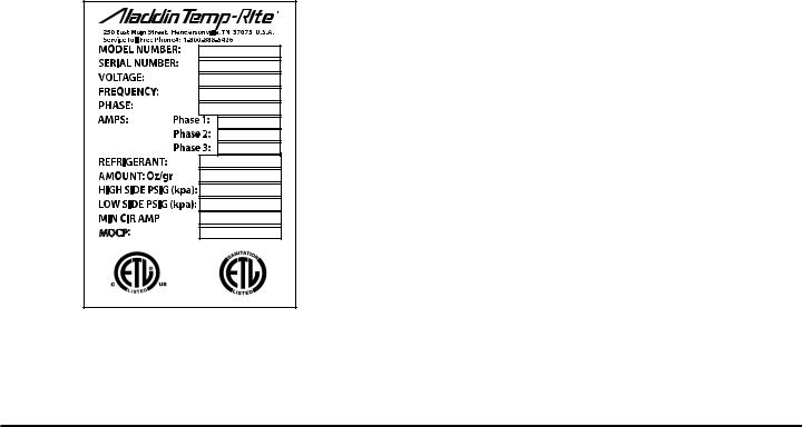
SERIAL / PRODUCT INFORMATION PLATES
MOCP |
#96712 |
Figure 1-3 |
During manufacture, Convect-Rite™ III Docking Stations are assigned individual serial numbers. The serial number plate is located on the top left hand side of the black plastic top cover. The product information plate lists the model number, serial number, voltage, power and wiring requirements, amount and kind of refrigerant, pressure, and ETL listed mark. (See Figure 1-3)
II. RECEIVING INSPECTIONS
Your Aladdin Convect-RiteTM III Docking Station is factory tested for performance and is free from defects when shipped. The utmost care has been taken in packaging this product to protect against damage in transit. All interior fittings have been secured to prevent damage.
You should carefully inspect your Convect RiteTM III components to assure that no damage has occurred in transit. If however, damage is detected, you should save all the packaging materials and make note on the carriers Bill of Lading describing this shipment. A freight claim should be filed immediately. If damage is subsequently noted during or immediately after installation, contact the respective carrier and file a freight claim. Under no condition may a damaged unit be returned to Aladdin Temp-Rite without first obtaining written permission (return authorization).
PACKAGING:
Your Convect RiteTM III Docking Station is packaged with care and shipped on dedicated carriers to you from the factory.
IMPORTANT NOTE:
Aladdin Temp-Rite does not recommend laying the unit down on its front, side or back. However, if you must, please be certain to allow the unit to remain in an upright position for 24 to 48 hours before attempting to place the unit into service, to assure that the compressor oils and refrigerant may settle.
ALADDIN DAMAGED GOODS POLICY There are two types of damaged merchandise:
A.VISIBLE DAMAGE OR SHORTAGE
B.CONCEALED DAMAGE
8 |
FOR SERVICE CALL - ALADDIN TEMP-RITE® - Tech Service 1 (800) 888-5426 |

A.VISIBLE DAMAGE OR SHORTAGE - (All claims should be reported within 10 business days)
1.Receiver should refuse the damaged portion of the shipment.
2.Receiver should sign the bill of lading indicating (delivery receipt) what merchandise is being “refused due to damage” and have the driver initial the notation.
3.Receiver should note any shortages on the bill of lading (delivery receipt) in the same manner.
4.Receiver should contact Aladdin Customer Service at 1-800-888-8018 and alert them to the situation.
B.CONCEALED DAMAGE- (All claims should be reported within 10 business days) Any receiving operation should inspect for this type of damage.
IF PRODUCT IS DAMAGED
1.Receiver should hold the shipping container and its contents in the same condition as when the damage was discovered insofar as possible and call the delivering carrier to arrange on site inspection within 10 days of delivery.
2.Receiver should contact Aladdin Customer Service at 1-800-888-8018 for claims processing after inspection has been completed.
III.INSTALLATION INSTRUCTIONS
IMPORTANT NOTE:
DO NOT INSTALL a Convect-RiteTM III Docking Station if damage is suspected.
INJURY & EQUIPMENT DAMAGE could result from improper installation of the Con- vect-RiteTM III Docking Station or from installation of a unit damaged during shipment or storage. Either of these conditions will void the equipment warranty.
! WARNING !
DO NOT move a Convect-RiteTM III Docking Station up a slope greater than 10°.
DO NOT EVER tow a Convect-RiteTM III Docking Station
DO NOT push a Convect-RiteTM III Docking Station from the front or back side
FOR SERVICE CALL - ALADDIN TEMP-RITE® - Tech Service 1 (800) 888-5426 |
9 |

CONVECT-RITE |
|
III Docking Stations |
Manual |
|
™ |
|
Installation & Service |
|
|
|
|
|
|
|
|
! CAUTION !
Casters are ONLY intended for use during installation or service.
Unit MUST be positioned securely against a wall during operation!
INTRODUCTION
Install the Convect-RiteTM III Docking Station according to the policies and procedures outlined in this manual. After selecting and preparing the Convect-Rite™ III Docking Station operating location, the unit can be positioned and installed. When installation is complete, perform all start-up checks to verify proper installation and operation.
This section is a guide for installation of the Convect-RiteTM III models identified in the Introduction section of this manual. This guide is for use by qualified
professionals, and does not include all procedures and precautions in the common domain of licensed plumbers, pipe fitters, and electricians or experienced food service equipment installers.
This guide MUST be used in conjunction with professional experience and thorough understanding of the local and national utility, construction & sanitation codes.
Before starting installation, the owner and the installer should read through this chapter and thoroughly understand and agree upon:
•The installation policies of Aladdin Temp-Rite® as stated in Installation Policies Section.
•An installation plan based on the Installation Instructions and Start-Up Check
List
10 |
FOR SERVICE CALL - ALADDIN TEMP-RITE® - Tech Service 1 (800) 888-5426 |
INSTALLATION POLICIES
The Convect-RiteTM III Docking Station must be installed by qualified electrical, mechanical, or refrigeration personnel, working to all applicable national and local codes. Equipment installation must comply with the local and national codes.
•All models of the Convect-RiteTM III Docking Station comply with the applicable standards for manufacturers. Included among those certification agencies are: ETL Safety and ETL
Sanitation.
•The Convect-RiteTM III Docking Station is certified for safe operation only when permanently installed in accordance with local and/or national codes. Many local codes exist, and it is the responsibility of the owner and installer to comply with these codes.
•In no event shall Aladdin Temp-Rite assume any liability for damage or injury resulting from installations which are not in strict compliance with the Installation, Instructions and the codes cited above. Specifically, Aladdin Temp-Rite will not assume any liability for damage or injury resulting from improper installation of equipment, including but not limited to temporary or mobile installations.
ELECTRIC POWER REQUIREMENTS
Unit should be hard wired to electrical disconnect requirements specified which can also be found on the product identification plate. The plate is secured to the top on the left hand side as you look at the front of the unit as mentioned in serial/product information plate section. 208 volts / 3 phase / 30 amp circuit / 4 wire (3 hots & 1 ground)
SELECTING THE OPERATING LOCATION
For safe and efficient operation, observe the following criteria when selecting an operating location for the Convect-Rite™ III Docking Station.
IMPORTANT NOTE:
The flooring directly under this unit must be made of non-combustible material and be capable of supporting the weight of this equipment.
1.Do not install these units in areas where combustibles are stored or may accumulate. The surrounding area must be clear of combustibles, including the space under the unit.
2.A proper air supply for ventilation is critical to safe, efficient operation of the
Docking Station. The area around the Docking Station must have adequate ventilation and the ambient temperature should never be above 85°F (35°C).
3.Do not block the louvers or panels. Do not install any heat producing equipment near the louvers of the unit. Ventilation occurs through open slots on the dock’s right side and through louvers on the back of the dock.
FOR SERVICE CALL - ALADDIN TEMP-RITE® - Tech Service 1 (800) 888-5426 |
11 |

CONVECT-RITE |
|
III Docking Stations |
Manual |
|
™ |
|
Installation & Service |
|
|
|
|
|
|
|
|
4.The dimension drawings in Figure 3-1 specify all dimensions and clearances required for proper installation operation and service of the Convect-Rite™ III
Docking Station, covered in this manual. Maintain at least a 6” (15.2 cm) operating clearance between foot pedals of units, at least 10” (25.4 cm) between foot pedal and sidewall, at least 18” above the unit, and at least a 5 3/4” (14.6 cm) clearance at the back of the unit. The front and rear door swing of the cart is 30” (750 cm).
5.The condensing unit and controller can be accessed by removing the black plastic top cover. Removable side panels provide access for service of various components; the right side for the cold side blowers and control panel and the left side for the hot side motors. The back access panel permits service to the cold side motors and expansion valves. Removing the left side perforation panels allows access to the hot side heaters and blowers. A minimum 6” (15.16 cm) clearance should be available on both sides of the unit. For access to the back and side panels the Docking Station should be lowered onto the casters and pulled away from the wall where it can be turned 90°-180° for ease of service.
6.The location selected must be capable of supporting the operational weight of the Convect-Rite™ III system including the weight of the Convect-Rite™ III cart loaded with trays, crockery, and food-products. See Table 1-1 for equipment weights.
7.The floor surface under the unit must be level and continuous with the flooring in front of the unit. The cart must roll smoothly to the Docking
Station for ease of operation and maintenance of the seal between the
Docking Station and the cart.
Minimum |
|
|
|
18” Clearance |
Minimum |
|
|
(45.7 cm) |
|
|
|
|
5-3/4” Clearance |
|
|
|
|
(14.6 cm) |
|
|
|
FRONT DOOR SWING |
|
|
|
R |
30" |
|
|
75 cm |
|
|
Minimum |
|
|
Minimum |
clearance |
|
R |
between |
|
REAR DOOR SWING |
|
Clearance |
foot pedals |
|
30" |
10” (25.4 cm) |
6” (15.2 cm) |
75 cm |
|
|
|
|
|
Figure 3-1
12 |
FOR SERVICE CALL - ALADDIN TEMP-RITE® - Tech Service 1 (800) 888-5426 |
WALL MOUNTING INSTRUCTIONS
IMPORTANT NOTE:
The wall directly behind the Docking Station must be able to support the average cart Docking force of 550 lbs. Based on the condition of the support wall, a reinforcing horizontal or vertical brace may be required at the upper and lower wall contact points, for better stability. See figure below for details.
Support braces should be: 1) 2” x 6” X 3’
SPIB Southern pine wood or equivalent 2) 8” X 3’
10 Gauge 304 Stainless steel or equivalent
3) Use optional Aladdin wall mounting kit PN 98507
50” (127 cm)
13” (33 cm)
FOR SERVICE CALL - ALADDIN TEMP-RITE® - Tech Service 1 (800) 888-5426 |
13 |
CONVECT-RITE |
|
III Docking Stations |
Manual |
|
™ |
|
Installation & Service |
|
|
|
|
|
|
|
|
Inspected for shipping damage (see Section II. RECEIVING INSPECTION)
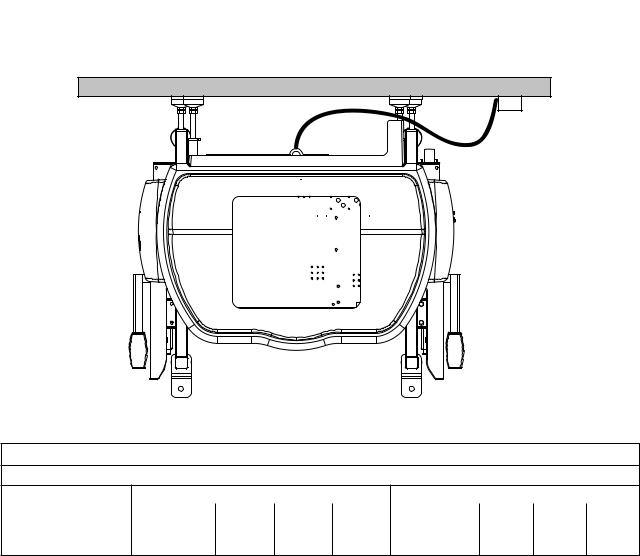
CONNECT ELECTRICAL LINE
Electrical schematic diagrams can be found in Section VI. PREVENTIVE MAINTENANCE. Connect the electrical cord to the electric connection box as described in Figure below. Refer to Table 3-1 for amperage distribution
3/4" Liquidtight conduit Dedicated electrical disconnect or J-box
Table 3-1
Convect-Rite™ III Docking Station
208V / 3PH /4 WIRE/ |
24 Meal Unit (CR3D0XXX1) |
|
30 Meal Unit (CR3D1XXX1) |
|
||||
(3 hot, 1 ground)/ 60 |
Power |
PH1 |
PH2 |
PH3 |
Power |
PH1 |
PH2 |
PH3 |
HZ |
Watts |
Amps |
Amps |
Amps |
Watts |
Amps |
Amps |
Amps |
|
|
|
|
|
|
|
|
|
Product Total |
9.3 kw MAX* |
26 |
25 |
25 |
10 kw MAX* |
28 |
27 |
27 |
*Actual duty load during rethermalization cycle is approximately 75% of maximum power requirements.
14 |
FOR SERVICE CALL - ALADDIN TEMP-RITE® - Tech Service 1 (800) 888-5426 |

TEst boot
With the unit still on all four casters, and after the hard wire connection is complete, switch the breaker on for the unit and then turn on the unit (the switch located on the upper right front of the unit). The unit should boot up and the screen should display the time & “Idle”
(see figure to right) Turn the unit and breaker back off. If the unit does not boot correctly check electrical connection. For further information call Aladdin Tech Service 1 (800) 888-5426.
setting against the Wall
Make adequate space and thoroughly clean the location before you begin the install.The Docking Station has eight adjustable feet (four on the back & four on the bottom). When starting the install process all eight feet should be completely seated. Gently push unit within 1/4” of the wall. Loosen the 7/8” jam nuts on the back four feet. Adjust all four back feet close to the wall but not touching it. Extend one foot at a time to touch the wall, trying to keep the unit parallel to the wall as possible (due to wall inconsistency all four feet may be adjusted to different lengths) NOTE: Recommend adjusting the top feet until the Docking Station sits at a 5° angle away from the wall as a starting position.
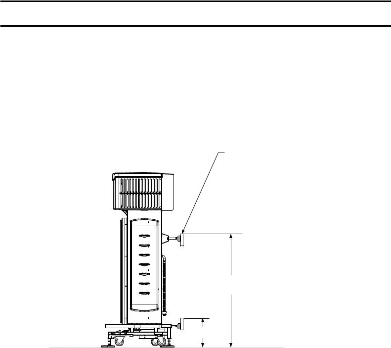
LIFTING THE UNIT OFF THE CASTERS
NOTE: If feet are unevenly set the unit’s frame may be damaged by racking.
The Convect-Rite™ III Docking Station MUST BE LEVEL BOTH FRONT TO BACK AND SIDE TO
SIDE. Depending on floor condition reference gasket alignment between the cart and Docking Station to insure proper gasket seal for correct positioning.
Ensure that both caster locks point away from the wall, and are 90˚ to the wall in the locked position.
The four feet on the base of the Docking Station are adjustable to achieve this. Be mindful when setting the feet that:
•A Docking Station set too low can result in interference between the lower cart hinge and the Docking Station interface channel.
•A Docking Station set out of level right-to-left can result in an insufficient seal between the unit and the gaskets on the cart.
•A Docking Station set out of level front-to-back can result in an insufficient seal between the unit and cart and possibly make mating the cart more
difficult.
Loosen the 7/8” jam nuts on the four bottom feet. Then adjust the |
|
|
||
four feet close to the floor, but not touching it. Slowly continue to |
7.1” |
|||
extend each foot a turn at a time, until the top of the base is 7.1” |
||||
|
|
|||
(see diagram) off the ground (the caster should be off the ground at |
|
|
||
this point). However, due to floor inconsistency, all four feet may be |
|
|
|
|
adjusted to different lengths |
|
|
||
FOR SERVICE CALL - ALADDIN TEMP-RITE® - Tech Service 1 (800) 888-5426 |
15 |
|||
CONVECT-RITE |
|
III Docking Stations |
Manual |
|
™ |
|
Installation & Service |
|
|
|
|
|
|
|
|
EXtending the rear feet against the wall
NOTE: Shims should NOT be used.
Adjust back feet until they are tight against the wall. Check that the feet are not bowed, skewed, or have less than 3 threads protruding from rear brackets. If any of these conditions occur, the dock should be lowered back on its casters and moved closer to the wall.
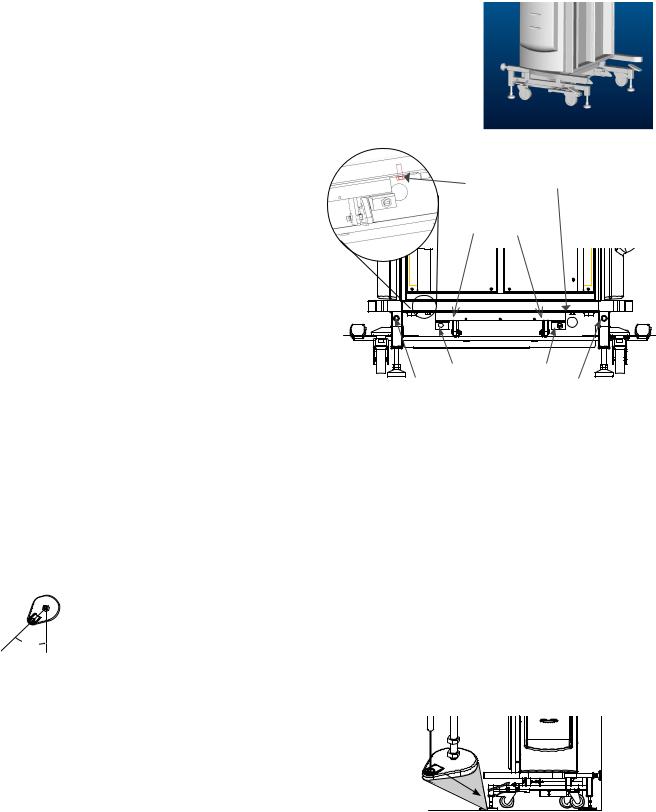
ADJUSTING THE SEAL & Latches
Roll a Convect Rite III Retherm Cart up to the front of the Docking Station with the door open on the non-handle end of the cart. NOTE: if
Docking Station is too low the cart will run into the door support. If the cart does not hit
the door support, dock the cart to the unit.
Adjust any necessary feet until a uniform compression seal is formed around the cart. You many need to dock & undock the cart several time to ensure a proper fit.
If the cart does not depress the latches when engaged to the dock, (see diagram for
location) the latches need to be adjusted. To adjust first loosen the holding screws, adjust the latch bolts so the switches are in contact with the cart. To move the switches forward, turn the bolts clockwise. To move backward, turn counter clockwise. Tighten the holding screws.
Mounting to the floor
The Docking Station should be secured to the floor with floor anchors that are included with the unit.
Turn the feet out 45°, for better stability . Select a carbide drill bit equal to the
 45° anchor diameter, 1/2”. Drill hole to desired depth suitable for the floor type. A minimum embedment of 1-7/8” is required for concrete. Clean hole or continue drilling additional depth to accommodate floor finish. Assemble washer and nut,
leaving nut flush with end of anchor to protect threads. Drive anchor through the foot until the washer is flush. Expand anchor by tightening 


nut 3 to 5 turns past the hand tight position, or 25 ftlbs. torque.
16 |
FOR SERVICE CALL - ALADDIN TEMP-RITE® - Tech Service 1 (800) 888-5426 |
Loading...