


CONVECT-RITE
™
Air Cooled
III
Manual P/N 97394
Rev. K 10/23/2009
Convect-Rite™ III
Docking Stations
24 Meal Capacity (CR3D0XXX1)
30 Meal Capacity (CR3D1XXX1)
Used with
Convect-Rite™III Cart manual 98893
or
Convect-Rite™ Trans-Tray System manual 98871
U.S. Patent Number 7,025,121
INSTALLATION & SERVICE MANUAL

Copyright © 2004 Aladdin Temp-Rite
®
Changes may be made to the information in this document without notication.

MEAL
ENTER
MANUAL
MODE
AUTO
MODE
B
L
D
MANUAL
HOLD
MAN.
RETHERM
PM
PROGRAM
ALARM
SILENCE
CHILLING
RETHERM
EQUALIZE
HOLDING
DEFROST
R
3-18-03
CHILLING
Mode: (Green LED
illuminated) Cart is engaged.
After a 5 second delay, both the
hot side and cold side chambers
will be subjected to refrigeration
cooling to satisfy temperature
set points programmed into
the controller.
RETHERM
Mode: (Green LED illuminated)
The hot side chamber will receive
heating while the cold side chamber
will receive refrigeration cooling. This
cycle is used to rethermalize food on the
hot side of the cart. This mode can be
started using either the MANUAL RETHERM
key or pre-programmed meal times (AUTO
MODE). The timer will display the number of
remaining minutes in the retherm cycle and
Default Time
(Minutes)
Breakfast
Lunch &
Dinner
count down to zero.
24 Meal 30 Meal
38 45
48 55
IDLE
Mode: (Red AUTO MODE
or Red MANUAL MODE LED
illuminated) The Convect-Rite™
III system is powered up. No cart
is engaged. The alphanumeric
display shows the word
“Idle”.
EQUALIZE
Mode: (Green LED illuminated)
After the Convect-Rite III nishes the
RETHERM mode, it will automatically
move into the EQUALIZE mode (default
duration for the 24 meal dock is 10 minute,
for the 30 meal dock is 5 minute). During this
mode, the temperature set point for the hot
side chamber has a lower setting to allow for
temperature saturation throughout the cart.
The fans will continue to run to enhance
the saturation process. The cold side
chamber will continue to receive
refrigeration cooling.
ALARMS
An alarm can arise at any
point during the operation of the
Docking Station. A buzzer will sound
to indicate an alarm has been activated
and both the Red ALARM LED and the red
SILENCE LED will blink on and off. The
alphanumeric display will show which alarm
occurred. Press SILENCE key to silence
the alarm buzzer (the Red ALARM LED will
remain illuminated if the alarm condition
exists). The alarm will terminate once
the alarm condition is satised. See
the Owner’s Manual for all alarm
displays and descriptions.
Mode: (Red LED illuminated) The
HOLDING
HOLDING mode includes a sounding
alarm to indicate the rethermalization
process (RETHERM + EQUALIZE) is
complete. The cart can be removed at any
time. The temperature set point for the hot side
chamber has a lower setting than the EQUALIZE
mode. The fans will continue to run to enhance
the saturation process. The timer will display
the number of minutes held and count up to the
duration setting (default 10 minute duration,
max. hold 60 minute duration). Once the
programmed holding time is reached, all
heating and refrigeration will cease
operation and a second alarm will
sound continuously until the cart
is removed.
DEFROST
Mode: (Green LED illuminated)
If CHILLING mode continues for an
extended amount of time, the DEFROST
mode may be automatically activated.
During this mode, the refrigeration cooling
used during the CHILLING mode will turn off for
the programmed duration (default 10 minutes) of
the DEFROST mode. The fans will still operate.
This mode ensures the coils inside the dock do
not freeze while receiving extended periods of
refrigeration cooling in the CHILLING mode.
Once the DEFROST duration expires ,the
system will return to the CHILLING
mode. This mode will not activate
during the rethermalization
cycle.


CONVECT-RITE™ III Docking Stations
CONTENTS
I. INTRODUCTION 6
Convect-Rite™ III Docking Stations 6
II. RECEIVING INSPECTIONS 8
III. INSTALLATION INSTRUCTIONS 9
INTRODUCTION 10
INSTALLATION POLICIES 11
ELECTRIC POWER REQUIREMENTS 11
SELECTING THE OPERATING LOCATION 11
TEST BOOT 15
Installation & Service
Manual
SETTING AGAINST THE WALL 15
LIFTING THE UNIT OFF THE CASTERS 15
ADJUSTING THE SEAL & LATCHES 16
MOUNTING TO THE FLOOR 16
IV. PARTS LIST & ILLUSTRATION 22
24- Meal (CR3D0XXX1) 22
30- Meal (CR3D1XXX1) 26
V. OPERATION & PROGRAMMING 30
VI. PREVENTIVE MAINTENANCE 31
INTRODUCTION 31
OPERATOR’S TROUBLESHOOTING 33
TROUBLESHOOTING NOTES 33
SERVICING PROCEDURES 39
REPAIRING THE REFRIGERATION SYSTEM 42
PUMP DOWN 42
WIRING DIAGRAMS 44
VII. WARRANTY 52

CONVECT-RITE™ III Docking Stations
I. INTRODUCTION
Convect-Rite™ III Docking Stations
The Convect-Rite™ III Docking Stations are installed and electrically connected in the
ward pantry for a decentralized operation or grouped in one area for a centralized operation. Operation and programming of these units is shown in the Owners Manual. The
Convect-RiteTM III Docking Station is a dual cold and hot air-generator, which may be
used up to three times a day in the Auto mode:
•
To keep the meals at the recommended and safe temperature of
37/41°F (+3°C/+5°C) during stand-by periods prior to rethermalization.
•
To rethermalize starters, soups, hot desserts or main-courses in
approximately 50-60 minutes before service.
•
IMPORTANT NOTE: The food products in the cold section, should be at
maximum homogeneous 50°F (10°C) temperature when loaded inside the
cart, so that the Convect-RiteTM III System can keep them between 37
and 41°F (+3° and +5°C) at the end of the chill-down and rethermalization
cycle.
•
A minimum chill-down cycle of 50 minutes is recommended prior to
rethermalization to assure the lowest possible cold food temperatures.
Installation & Service
Manual
6
FOR SERVICE CALL - ALADDIN TEMP-RITE® - Tech Service 1 (800) 888-5426

MODELS
This manual covers the standard models for the Convect-Rite™ III Docking Station that
accommodates 24 or 30 meals depending on the unit. Information for the ConvectRiteTM III System is listed in the table below. See below for dimensions.
TABLE 1-1
Tray Capacity, Dimensions, Weight, Electrical Data, & Heat Load Requirements
DIM CONVECT RITETM SYSTEM
A LENGTH/DEPTH
B WIDTH
C HEIGHT
MODELS
ALADDIN SALES CODE FOR
STANDARD MODELS
TRAY CAPACITY
TRAY SPACING
(OFF WALL FOR Docking Station)
WEIGHT
SHIPPING WEIGHT
Cart TURNING RADIUS n/a n/a
MAX HEAT EMISSIONS
@ 70oF AMBIENT
COOLING CAPACITY 6000 BTU/HR 7500 BTU/HR
ELECTRICAL REQUIREMENTS 208V - 3 Phase - 60 HZ / 4 Wire - 30 Amp
24 Meal 30 Meal
CR3D0XXX1 CR3D1XXX1
n/a n/a
32.56”
41.69”
77.63”
530 lb
550 lb
7900 BTU/HR 9900 BTU/HR
Docking Station
(82.7 cm)
(108.89 cm)
(197.18cm)
(240.4 kg)
(249.5kg)
(Hard wire connection required)
32.56”
41.69”
82.08”
573 lb
593 lb
(82.7 cm)
(108.89 cm)
(208.5 cm)
(259.9 kg)
(268.9 kg)
SPECIFICATIONS
CONVECT RITE™ III Docking Station
B
C
A
FOR SERVICE CALL - ALADDIN TEMP-RITE® - Tech Service 1 (800) 888-5426
7

CONVECT-RITE™ III Docking Stations
#96712
MOCP
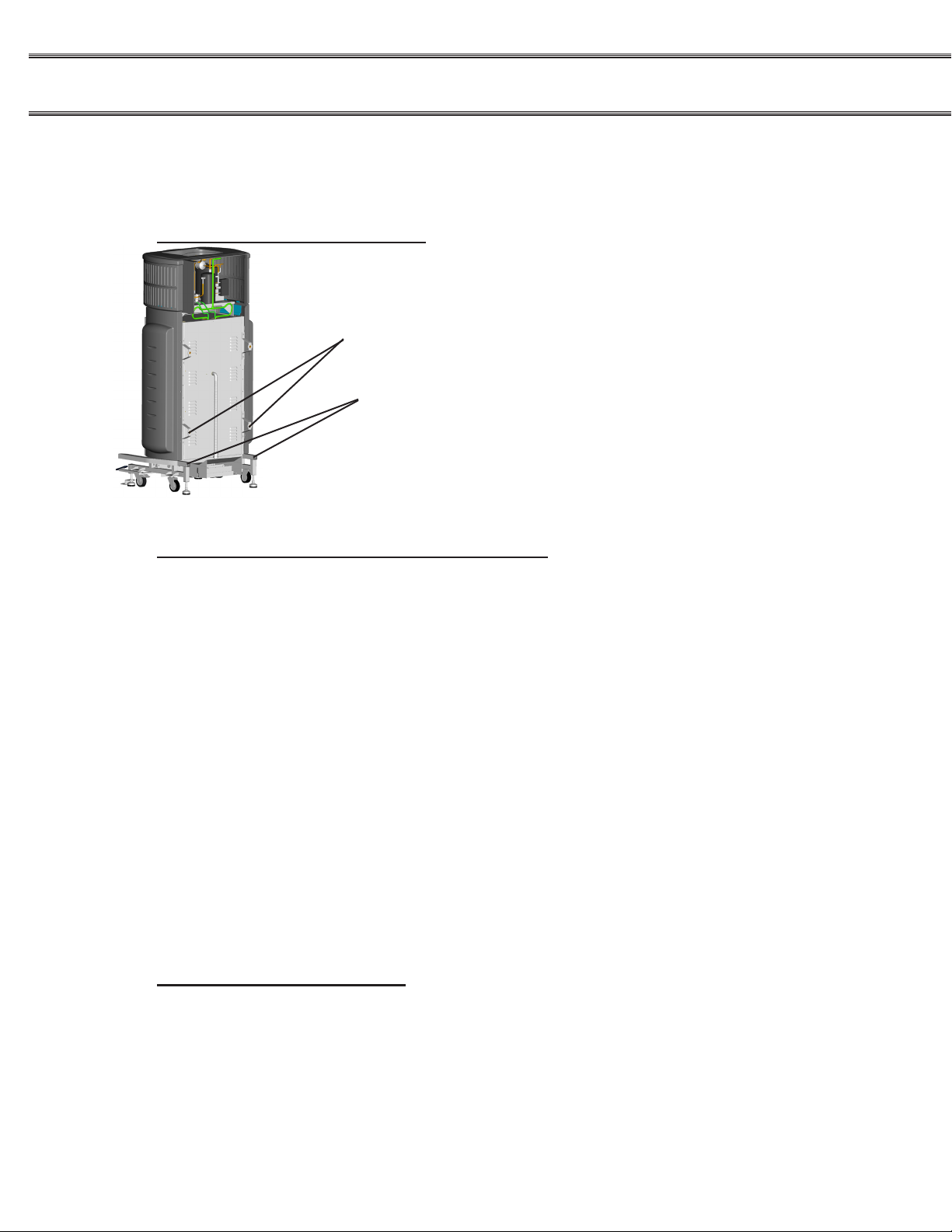
SERIAL / PRODUCT INFORMATION PLATES
During manufacture, Convect-Rite™ III Docking Stations are
assigned individual serial numbers. The serial number plate is
located on the top left hand side of the black plastic top cover. The
product information plate lists the model number, serial number,
voltage, power and wiring requirements, amount and kind of
refrigerant, pressure, and ETL listed mark. (See Figure 1-3)
Installation & Service
Manual
Figure 1-3
II. RECEIVING INSPECTIONS
Your Aladdin Convect-RiteTM III Docking Station is factory tested for performance and is free from
defects when shipped. The utmost care has been taken in packaging this product to protect against
damage in transit. All interior ttings have been secured to prevent damage.
You should carefully inspect your Convect RiteTM III components to assure that no damage has occurred in transit. If however, damage is detected, you should save all the packaging materials and
make note on the carriers Bill of Lading describing this shipment. A freight claim should be led
immediately. If damage is subsequently noted during or immediately after installation, contact the
respective carrier and le a freight claim. Under no condition may a damaged unit be returned to
Aladdin Temp-Rite without rst obtaining written permission (return authorization).
PACKAGING:
Your Convect RiteTM III Docking Station is packaged with care and shipped on dedicated carriers to
you from the factory.
IMPORTANT NOTE:
Aladdin Temp-Rite does not recommend laying the unit down on its front, side or back.
However, if you must, please be certain to allow the unit to remain in an upright position for 24 to 48
hours before attempting to place the unit into service, to assure that the compressor oils and refrigerant may settle.
ALADDIN DAMAGED GOODS POLICY
There are two types of damaged merchandise:
A. VISIBLE DAMAGE OR SHORTAGE
B. CONCEALED DAMAGE
8
FOR SERVICE CALL - ALADDIN TEMP-RITE® - Tech Service 1 (800) 888-5426

A. VISIBLE DAMAGE OR SHORTAGE - (All claims should be reported within 10 business days)
1. Receiver should refuse the damaged portion of the shipment.
2. Receiver should sign the bill of lading indicating (delivery receipt) what merchandise is being
“refused due to damage” and have the driver initial the notation.
3. Receiver should note any shortages on the bill of lading (delivery receipt) in the same manner.
4. Receiver should contact Aladdin Customer Service at 1-800-888-8018 and alert them to the
situation.
B. CONCEALED DAMAGE- (All claims should be reported within 10 business days)
Any receiving operation should inspect for this type of damage.
IF PRODUCT IS DAMAGED
1. Receiver should hold the shipping container and its contents in the same condition as when the
damage was discovered insofar as possible and call the delivering carrier to arrange on site
inspection within 10 days of delivery.
2. Receiver should contact Aladdin Customer Service at 1-800-888-8018 for claims processing
after inspection has been completed.
III. INSTALLATION INSTRUCTIONS
IMPORTANT NOTE:
DO NOT INSTALL a Convect-RiteTM III Docking Station if damage is suspected.
INJURY & EQUIPMENT DAMAGE could result from improper installation of the Con-
vect-RiteTM III Docking Station or from installation of a unit damaged during shipment
or storage. Either of these conditions will void the equipment warranty.
! WARNING !
DO NOT move a Convect-RiteTM III Docking Station up a slope
greater than 10°.
DO NOT EVER tow a Convect-RiteTM III Docking Station
DO NOT push a Convect-RiteTM III Docking Station from the front
or back side
FOR SERVICE CALL - ALADDIN TEMP-RITE® - Tech Service 1 (800) 888-5426
9

CONVECT-RITE™ III Docking Stations
! CAUTION !
Casters are ONLY intended for use during installation or service.
Unit MUST be positioned securely against a wall during operation!
INTRODUCTION
Install the Convect-RiteTM III Docking Station according to the policies and procedures
outlined in this manual. After selecting and preparing the Convect-Rite™ III Docking
Station operating location, the unit can be positioned and installed. When installation
is complete, perform all start-up checks to verify proper installation and operation.
This section is a guide for installation of the Convect-RiteTM III models identied
in the Introduction section of this manual. This guide is for use by qualied
professionals, and does not include all procedures and precautions in the common
domain of licensed plumbers, pipe tters, and electricians or experienced food
service equipment installers.
Installation & Service
Manual
This guide MUST be used in conjunction with professional experience and thorough
understanding of the local and national utility, construction & sanitation codes.
Before starting installation, the owner and the installer should read through
this chapter and thoroughly understand and agree upon:
• The installation policies of Aladdin Temp-Rite® as stated in Installation Policies
Section.
• An installation plan based on the Installation Instructions and Start-Up Check
List
10
FOR SERVICE CALL - ALADDIN TEMP-RITE® - Tech Service 1 (800) 888-5426

INSTALLATION POLICIES
The Convect-RiteTM III Docking Station must be installed by qualied electrical, mechanical, or refrigeration personnel, working to all applicable national and local codes. Equipment installation must comply with the local and national codes.
All models of the Convect-RiteTM III Docking Station comply with the applicable standards
•
for manufacturers. Included among those certication agencies are: ETL Safety and ETL
Sanitation.
The Convect-RiteTM III Docking Station is certied for safe operation only when perma-
•
nently installed in accordance with local and/or national codes. Many local codes exist,
and it is the responsibility of the owner and installer to comply with these codes.
In no event shall Aladdin Temp-Rite assume any liability for damage or injury resulting
•
from installations which are not in strict compliance with the Installation, Instructions and
the codes cited above. Specically, Aladdin Temp-Rite will not assume any liability for
damage or injury resulting from improper installation of equipment, including but not limited to temporary or mobile installations.
ELECTRIC POWER REQUIREMENTS
Unit should be hard wired to electrical disconnect requirements specied which can also
be found on the product identication plate. The plate is secured to the top on the left hand
side as you look at the front of the unit as mentioned in serial/product information plate section. 208 volts / 3 phase / 30 amp circuit / 4 wire (3 hots & 1 ground)
SELECTING THE OPERATING LOCATION
For safe and efcient operation, observe the following criteria when selecting an operating
location for the Convect-Rite™ III Docking Station.
IMPORTANT NOTE:
The ooring directly under this unit must be made of non-combustible material and be capable of supporting the weight of this equipment.
1. Do not install these units in areas where combustibles are stored or may accumulate. The surrounding area must be clear of combustibles, including the
space under the unit.
2. A proper air supply for ventilation is critical to safe, efcient operation of the
Docking Station. The area around the Docking Station must have adequate
ventilation and the ambient temperature should never be above 85°F
(35°C).
3. Do not block the louvers or panels. Do not install any heat producing
equipment near the louvers of the unit. Ventilation occurs through open
slots on the dock’s right side and through louvers on the back of the dock.
FOR SERVICE CALL - ALADDIN TEMP-RITE® - Tech Service 1 (800) 888-5426
11

CONVECT-RITE™ III Docking Stations
R
FRONT DOOR SWING
30"
75 cm
R
REAR DOOR SWING
30"
75 cm
4. The dimension drawings in Figure 3-1 specify all dimensions and clearances
required for proper installation operation and service of the Convect-Rite™ III
Docking Station, covered in this manual. Maintain at least a 6” (15.2 cm) oper-
ating clearance between foot pedals of units, at least 10” (25.4 cm) between
foot pedal and sidewall, at least 18” above the unit, and at least a 5 3/4”
(14.6 cm) clearance at the back of the unit. The front and rear door swing
of the cart is 30” (750 cm).
5. The condensing unit and controller can be accessed by removing the black
plastic top cover. Removable side panels provide access for service of
various components; the right side for the cold side blowers and control panel
and the left side for the hot side motors. The back access panel permits
service to the cold side motors and expansion valves. Removing the left
side perforation panels allows access to the hot side heaters and blowers. A
minimum 6” (15.16 cm) clearance should be available on both sides of
the unit. For access to the back and side panels the Docking Station should
be lowered onto the casters and pulled away from the wall where it can be
turned 90°-180° for ease of service.
6. The location selected must be capable of supporting the operational weight
of the Convect-Rite™ III system including the weight of the Convect-Rite™
III cart loaded with trays, crockery, and food-products. See Table 1-1 for
equipment weights.
7. The oor surface under the unit must be level and continuous with the
ooring in front of the unit. The cart must roll smoothly to the Docking
Station for ease of operation and maintenance of the seal between the
Docking Station and the cart.
Installation & Service
Manual
12
Minimum
18” Clearance
(45.7 cm)
Minimum
Minimum
Clearance
10” (25.4 cm)
FOR SERVICE CALL - ALADDIN TEMP-RITE® - Tech Service 1 (800) 888-5426
clearance
between
foot pedals
6” (15.2 cm)
Minimum
5-3/4” Clearance
(14.6 cm)
Figure 3-1

WALL MOUNTING INSTRUCTIONS
IMPORTANT NOTE:
The wall directly behind the Docking Station must be able to support the average cart
Docking force of 550 lbs. Based on the condition of the support wall, a reinforcing
horizontal or vertical brace may be required at the upper and lower wall contact points, for
better stability. See gure below for details.
Support braces should be:
1) 2” x 6” X 3’
SPIB Southern pine wood or equivalent
2) 8” X 3’
10 Gauge 304 Stainless steel or equivalent
3) Use optional Aladdin wall mounting kit PN 98507
50” (127 cm)
13” (33 cm)
FOR SERVICE CALL - ALADDIN TEMP-RITE® - Tech Service 1 (800) 888-5426
13

CONVECT-RITE™ III Docking Stations
Dedicated electrical
disconnect or J-box
3/4" Liquidtight conduit
Installation & Service
Manual
INSPECTED FOR SHIPPING DAMAGE (see Section
CONNECT ELECTRICAL LINE
Electrical schematic diagrams can be found in Section VI. PREVENTIVE MAINTENANCE.
Connect the electrical cord to the electric connection box as described in Figure below.
Refer to Table 3-1 for amperage distribution
II. RECEIVING INSPECTION)
14
Table 3-1
Convect-Rite™ III Docking Station
208V / 3PH /4 WIRE/
(3 hot, 1 ground)/ 60
HZ
Product Total 9.3 kw MAX* 26 25 25 10 kw MAX* 28 27 27
*Actual duty load during rethermalization cycle is approximately 75% of maximum power
requirements.
24 Meal Unit (CR3D0XXX1) 30 Meal Unit (CR3D1XXX1)
Power
Watts
PH1
Amps
PH2
Amps
PH3
Amps
Power
Watts
PH1
Amps
PH2
Amps
FOR SERVICE CALL - ALADDIN TEMP-RITE® - Tech Service 1 (800) 888-5426
PH3
Amps

TEST BOOT
With the unit still on all four casters, and after the hard wire connection
is complete, switch the breaker on for the unit and then turn on the
unit (the switch located on the upper right front of the unit). The unit
should boot up and the screen should display the time & “Idle”
(see gure to right) Turn the unit and breaker back off. If the unit
does not boot correctly check electrical connection. For further
information call Aladdin Tech Service 1 (800) 888-5426.
SETTING AGAINST THE WALL
Make adequate space and thoroughly clean the location before you begin the install.The Docking
Station has eight adjustable feet (four on the back & four on the bottom). When starting the
install process all eight feet should be completely seated. Gently push unit within 1/4” of the
wall. Loosen the 7/8” jam nuts on the back four feet. Adjust all four back feet close to the
wall but not touching it. Extend one foot at a time to touch the wall, trying to keep the unit
parallel to the wall as possible (due to wall inconsistency all four feet may be adjusted to
different lengths) NOTE: Recommend adjusting the top feet until the Docking Station sits at
a 5° angle away from the wall as a starting position.
LIFTING THE UNIT OFF THE CASTERS
NOTE: If feet are unevenly set the unit’s frame may be damaged by racking.
The Convect-Rite™ III Docking Station MUST BE LEVEL BOTH FRONT TO BACK AND SIDE TO
SIDE. Depending on oor condition reference gasket alignment between the cart and Docking Station to insure proper gasket seal for correct positioning.
Ensure that both caster locks point away from the wall, and are 90˚ to the wall in the locked
position.
The four feet on the base of the Docking Station are adjustable to achieve this. Be mindful
when setting the feet that:
• A Docking Station set too low can result in interference between the lower cart hinge and
the Docking Station interface channel.
• A Docking Station set out of level right-to-left can result in an insufcient seal between
the unit and the gaskets on the cart.
• A Docking Station set out of level front-to-back can result in an insufcient seal between
the unit and cart and possibly make mating the cart more
difcult.
Loosen the 7/8” jam nuts on the four bottom feet. Then adjust the
four feet close to the oor, but not touching it. Slowly continue to
extend each foot a turn at a time, until the top of the base is 7.1”
(see diagram) off the ground (the caster should be off the ground at
this point). However, due to oor inconsistency, all four feet may be
adjusted to different lengths
FOR SERVICE CALL - ALADDIN TEMP-RITE® - Tech Service 1 (800) 888-5426
7.1”
15

CONVECT-RITE™ III Docking Stations
Mirco Switches
EXTENDING THE REAR FEET AGAINST THE WALL
NOTE: Shims should NOT be used.
Adjust back feet until they are tight against the wall. Check that the
feet are not bowed, skewed, or have less than 3 threads protruding
from rear brackets. If any of these conditions occur, the dock should
be lowered back on its casters and moved closer to the wall.
Installation & Service
Manual
ADJUSTING THE SEAL & LATCHES
Holding Screws
Roll a Convect Rite III Retherm Cart up to the
front of the Docking Station with the door open
on the non-handle end of the cart. NOTE: if
Docking Station is too low the cart will run
into the door support. If the cart does not hit
the door support, dock the cart to the unit.
Adjust any necessary feet until a uniform
compression seal is formed around the cart.
You many need to dock & undock the cart
several time to ensure a proper t.
If the cart does not depress the latches
when engaged to the dock, (see diagram for
location) the latches need to be adjusted. To adjust rst loosen the holding screws, adjust
the latch bolts so the switches are in contact with the cart. To move the switches forward,
turn the bolts clockwise. To move backward, turn counter clockwise. Tighten the holding
screws.
Latch Adjustment Bolts
Latches
MOUNTING TO THE FLOOR
16
The Docking Station should be secured to the oor with oor anchors that are included with
the unit.
Turn the feet out 45°, for better stability . Select a carbide drill bit equal to the
45°
leaving nut ush with end of anchor to protect threads. Drive anchor through the foot until
the washer is ush. Expand anchor by tightening
nut 3 to 5 turns past the hand tight position, or 25 ftlbs. torque.
FOR SERVICE CALL - ALADDIN TEMP-RITE® - Tech Service 1 (800) 888-5426
anchor diameter, 1/2”. Drill hole to desired depth suitable for the oor type. A
minimum embedment of 1-7/8” is required for concrete. Clean hole or continue
drilling additional depth to accommodate oor nish. Assemble washer and nut,

STARTUP CHECK LIST
This inspection checks for proper electrical wiring to the Convect-Rite™ III Docking Sta-
tion and veries basic operation of the unit.
IMPORTANT NOTE:
Equipment damage and faulty operation will result if electrical supply falls below requirements. This may be caused by other equipment on the same supply line. Supply a
dedicated electric service for each unit.
Refer to the appropriate dimension drawing and verify that the specied
●
clearances are met (Fig 3.1).
● Verify that the voltage supplied complies with the voltage requirements speci-
ed on the Product Identication Plate, located on top of the unit. Verify that
the wiring connections are correct for these voltage requirements.
●
Connect the Convect-Rite™ III Cart to the Convect-Rite™ III Docking Station
with both cart doors opened.
● Turn the unit power-switch to the on position. After an 5 second delay, fan-
motor rotation should start.
● Operate a complete cycle (make sure door opposite Docking Station is closed)
to check every function of the Convect-Rite™ III unit. Temperatures set points
for the cold and hot sections are pre-set at the factory. Both can be adjusted
to meet customer’s requirements. (Refer to Section V of the owners manual
programming instructions)
● Verify cold air blowing and hot air ventilation functions.
FOR SERVICE CALL - ALADDIN TEMP-RITE® - Tech Service 1 (800) 888-5426
17
CONVECT-RITE™ III Docking Stations
OPTIONAL WALL MOUNT (required for OSHPD where applicable)
BACK MOUNTING BRACKETS
Remove lower feet from dock.
Add the wall mounting bracket (98076) to the dock from the OSHPD
mounting kit PN 98674.
Wall Mounting Brackets
Remove Feet
Installation & Service
Manual
STANDARD UPPER MOUNTING ASSEMBLY
The following is for wall mounting of a 24 shelf unit, refer to Figure 3-2 for 30 shelf units.
Step 1: To secure top horizontal support channel assembly measure 49-13/16” from
nished oor to center of 1-5/8” channel (See Figure 3-2). Conrm 1⅝” x 1⅝” Unistrut
channel is level and fasten to vertical wall surface using appropriate fastening devices
for wall surface encountered to insure equipment stability.
Step 2: Next measure 6-5/8” from center of “Unistrut” channel down to center of lower
channel and fasten to wall surface as directed above.
This “Unistrut” assembly will serve as an attachment point for the wall mounting
hardware detailed in Figure 3-3.
Note: Utilize an 8’-0” span of “Unistrut” when mounting two Docking Stations adjacent
to one another, and maintain 15” spacing between units for serviceability.
Step 3: Assemble mounting hardware to support brackets located at the rear of
Docking Station and fasten to “Unistrut” support channel assembly previously described
and detailed in Figure 3-3.
Note: Fasten Floor Mounts only after unit has been adjusted for proper t and seal with
retherm cart.
OPTIONAL LOWER MOUNT:
18
If a lower mount assembly is utilized then the following instructions apply. The lower wall
mount is identical to the upper mounting assembly. Mount upper “Unistrut” channel 235/16 to center of channel and proceed as directed in step 2 above.
FOR SERVICE CALL - ALADDIN TEMP-RITE® - Tech Service 1 (800) 888-5426

POSITION & LEVEL THE CONVECT-RITE™ III Docking Station
1.
The Convect-Rite™ III Docking Station MUST BE LEVEL BOTH FRONT TO BACK AND
SIDE TO SIDE. Depending on oor condition reference gasket alignment between the cart
and Docking Station to insure proper gasket seal for correct positioning.
2.
The oor must be at and smooth.
3.
Make adequate space and thoroughly clean the location.
4.
Leave the minimum clearances (see Figure 3-1) on each side of the Docking Station for
better ventilation and access for technical service.
The unit must sit level on a level oor. The unit must be level both front-to-back and right-
to-left. The four lower Docking Station feet are adjustable to achieve this. Be mindful when
setting the feet that:
• A Docking Station set too low can result in interference between the lower cart hinge and
the Docking Station interface channel.
• A Docking Station set out of level right-to-left can result in an insufcient seal between
the unit and the gaskets on the cart.
• A Docking Station set out of level front-to-back can result in an insufcient seal between
the unit and cart and possibly make mating a cart more difcult.
Open the door of the Convect-RiteTM III Cart opposite the handles and mate the cart to the
Convect-RiteTM III Dock Station. Conrm that the cart gasket seals against the docking
Stations interface channel around its full perimeter. Make the proper adjustments to the
Docking Station if the mating is not correct. Once the Docking Station level is set, tighten
all wall 7/8” jam nut to nal torque settings. Once the Docking Station is secure, anchor the
unit to the oor with provided hardware. If cart does not latch properly adjust latch position
(see “Adjusting the latches”)
MOUNTING TO THE FLOOR
The dock should be secured to the oor with the oor mounting brackets.
Turn the feet out 45°, for better stability . Select a carbide drill bit equal to the
45°
leaving nut ush with end of anchor to protect threads. Drive anchor through the foot
until the washer is ush. Expand anchor by tightening nut 3 to 5 turns past the hand
tight position, or 25 ft-lbs. torque.
anchor diameter, 1/2”. Drill hole to desired depth suitable for the oor type. A
minimum embedment of 1-7/8” is required for concrete. Clean hole or continue
drilling additional depth to accommodate oor nish. Assemble washer and nut,
FOR SERVICE CALL - ALADDIN TEMP-RITE® - Tech Service 1 (800) 888-5426
19

CONVECT-RITE™ III Docking Stations
1
2
3
4
5
6
7
Installation & Service
Manual
25-3/4”
Support channel 1-5/8” x 1-5/8”
(Unistrut)
25-3/4”
Center to Center of
mounting bracket
6-5/8” Center to Center
3-5/16”
Center to center
46-1/2” for 24 meal
50-3/4” for 30 meal
from center of upper
mounting plate to
nished oor.
20” from center of
mounting plate to
nished oor
OSHPD Mounting Kit Components
#
5/8”-11 jam nut 98627
1
5/8”-11x 6” full-thread stud 98626
2
Mounting plate for OSHPD 98672
3
3/8”-16 x 1-1/4” hex head bolt 39618
4
3/8” Belleville washer 97765
5
3/8”-16 channel nut 96332
6
Unistrut channel na
7*
*Item not supplied by ATR
Description PN
20
FOR SERVICE CALL - ALADDIN TEMP-RITE® - Tech Service 1 (800) 888-5426

OPTIONAL WALL MOUNT REQUIRED FOR OSHPD
C
*
A
FIGURE 3-3
24 Unit 30 Unit
A 20” 20”
B 46-1/2” 50-3/4”
C 77-5/8” 82-1/16”
* From center of mounting plate to nished oor.
B
*
FOR SERVICE CALL - ALADDIN TEMP-RITE® - Tech Service 1 (800) 888-5426
21

CONVECT-RITE™ III Docking Stations
Installation & Service
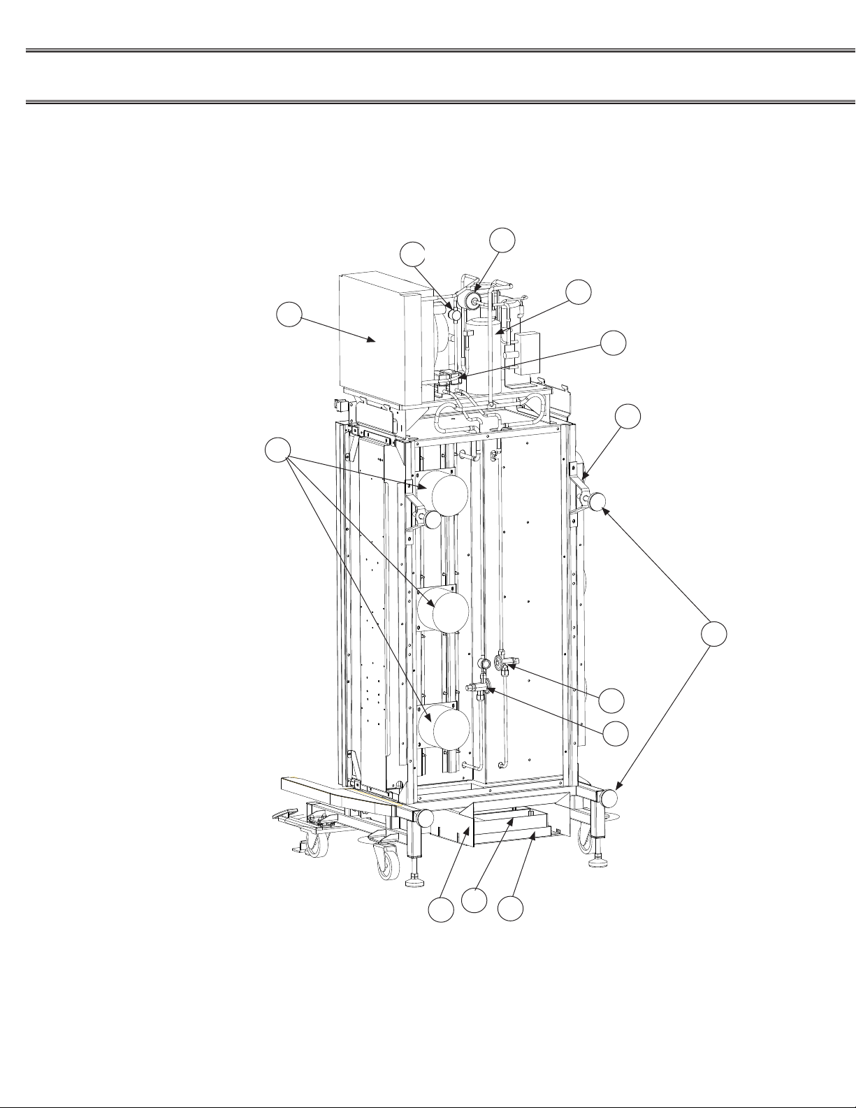
IV. PARTS LIST & ILLUSTRATION
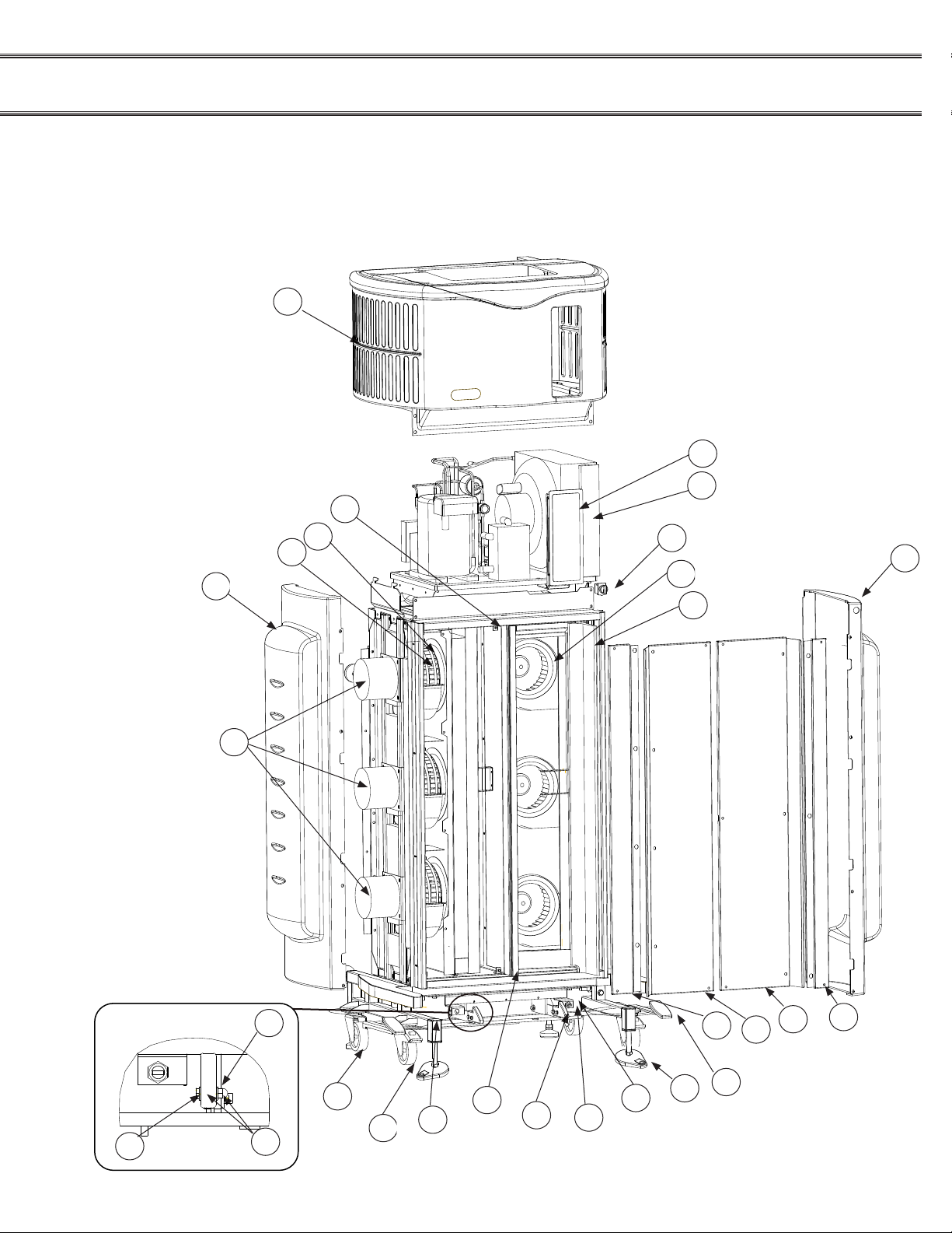
24- Meal (CR3D0XXX1)
Convect-Rite™ III Docking Station Parts List
(See Figures: 4-1 and 4-2)
Manual
ITEM# PART# DESCRIPTION
*1 98837 anchor, oor,1/2”,3/8”-16
*2 98774 compressor
3 96897 angle bracket
4 96734 blower wheel, cold side
5 96887 blower,wheel, hot side
6 96768 brass latch, foot pedal
7 98086 caster 4” swivel
8 98087 caster 4” swivel with brake
9 96783 clevis pin,3/8”,5/32” hole,1” lg
10 96996 condensing unit
11 96702 controller membrane ONLY, N7
12 96703 controller N7
13 96784 cotter pin,5/32” d,3/4”L
14 96717 cover,perf,cold,return
15 96713 cover,perf,cold,supply
16 96773 cover,perf,hot,return
17 96779 cover,perf,hot,supply
18 96758 dryer
19 96830 eps, vane,cold side
20 98191 evap pan bracket
21 98164 evap pan shroud
22 98117 evaporative pan assy
23 96816 extrusion, gasket,al,hold
24 na na
25 99763 foot pedal cover
26a 98838 foot, oor, tear drop
26b 98839 foot, back, round
*27 98189 gasket, interface
28 96742 heater coils for 8.5in dia blower
ITEM# PART# DESCRIPTION
*29 96688 heater gasket, silicone
*30 96811 housing eps
*31 96801 insulation, left hot side
*32 96889 insulation, lft fwd hot side
*33 96798 insulation, rear left cold side
*34 96800 insulation, rear mid cold side
*35 96799 insulation, rear right cold side
*36 96855 insulation, right cold side back
*37 96802 insulation, right cold side fwd
38 96728 motor, fan cold side and hot side
39 96898 receiver,copeland,577-0315-02
*40 96156 safe temp thermocouple (white wire)
41 96787 sensor nut,m14x1,260 brass
42 97751 side panel plastic(COLD)
43 97758 side panel plastic (HOT)
44 96759 site glass
45 96756 solenoid
46 96716 switch, on-off with light knob
47 96766 switch, limit, roller plunger, 9ft cable
*48 96792 thermocouple (right hand side of pair)
49 96785 thrust bearing,3/8” shft d, 3/4” od,1/8” t
50 98073 cap plastic
51 97754 top cover plastic
*52 98126 trim strip left & right side
*53 98348 trim strip top
54a 96993 valve, thermal expansion (cold)
54b 96993 valve,thermal expansion (hot)
55 98076 wall mount brackets
*56 98571 solenoid repair kit
22
The parts listed above are noted in Figures 4-1 and 4-2
Note: “*” Indicates items not shown in the diagram.
FOR SERVICE CALL - ALADDIN TEMP-RITE® - Tech Service 1 (800) 888-5426

24- Meal (CR3D0XXX1)
9
49
8
3
5
51
433813
23
41
6
47
24
14
15
16
17
42
11
12
19
46
25
28
7
4
50
26a
Convect-Rite™ III Docking Station Illustration
Figure 4-1
NOTE: Shown without evaporator on right side
FOR SERVICE CALL - ALADDIN TEMP-RITE® - Tech Service 1 (800) 888-5426
23
CONVECT-RITE™ III Docking Stations
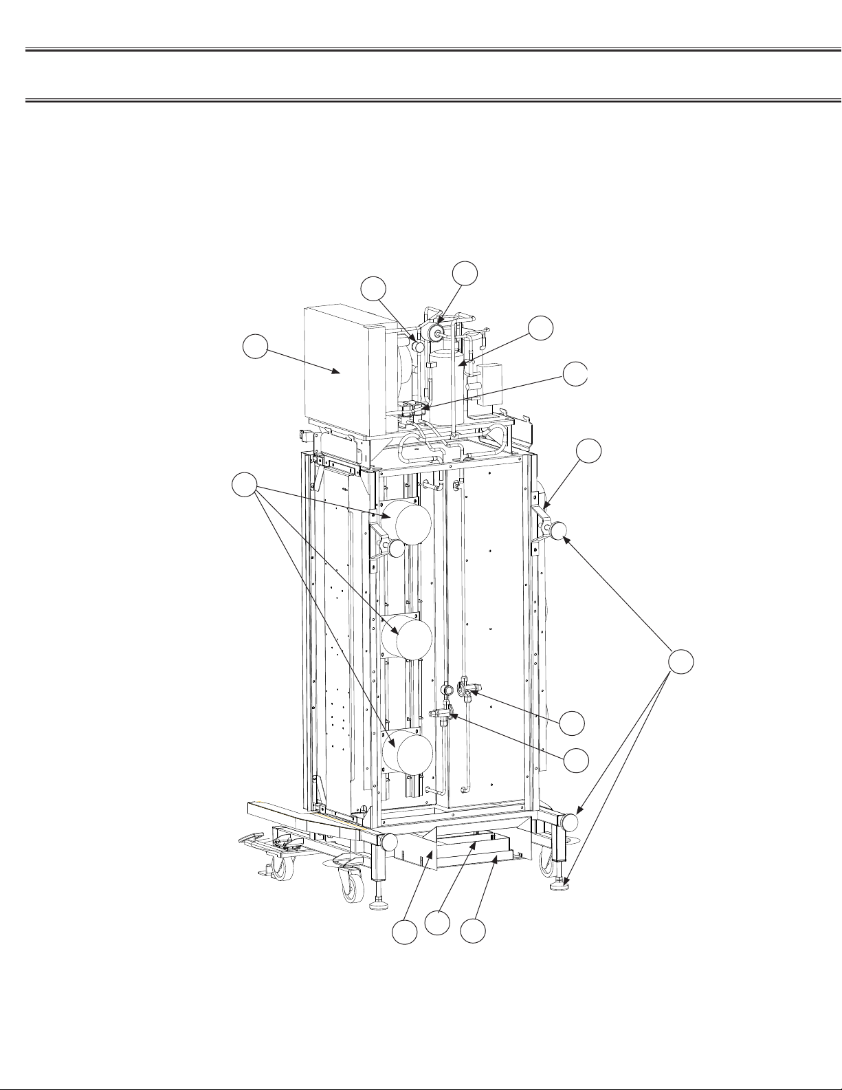
10
44
18
39
38
45
55
21
22
20
54a
54b
26b
24- Meal (CR3D0XXX1)
Convect-Rite™ III Docking Station Illustration
Installation & Service
Manual
24
Figure 4-2
FOR SERVICE CALL - ALADDIN TEMP-RITE® - Tech Service 1 (800) 888-5426
TB1
F1-3
CR1
CR3
CR4
CR2
TR1
TH1
F4-5
CB1
CB2
28
30
11
12
10
9
18
17
1
2
3
4
25
31
15
24- Meal (CR3D0XXX1)
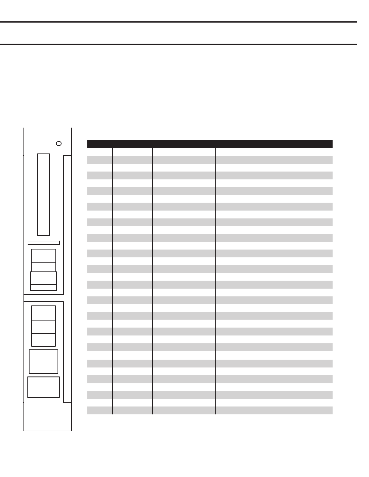
Convect-Rite™ III Electrical Layout and Parts List
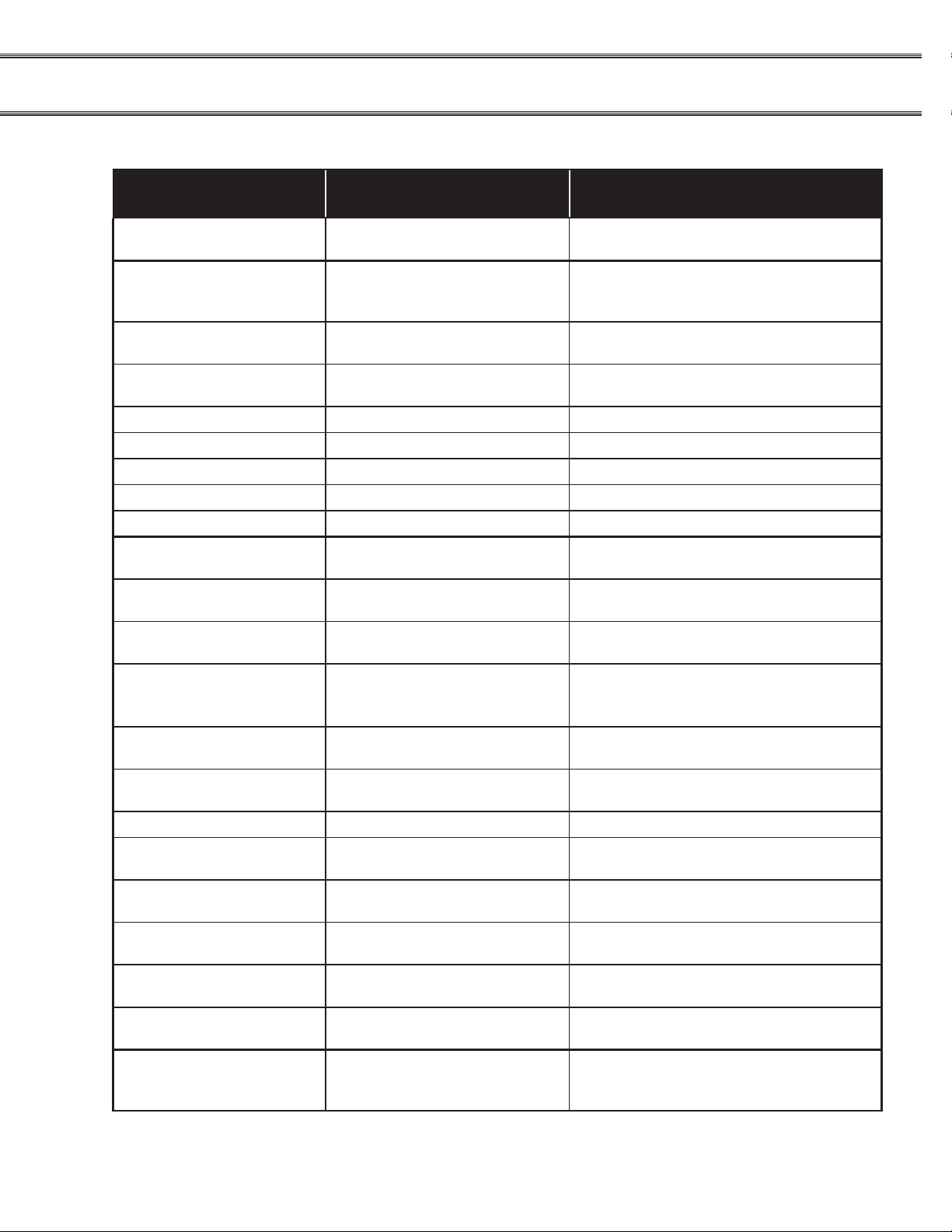
The electrical parts list below notes all “KEY” numbers in the control panel layout and illustrated in Figure 4-3.
KEY QTYSUPPLIER PART NUMBER DESCRIPTION
1 1 Aladdin 96910 Contactor,IEC 9 Amp,208 VAC,4 Pole
2 1 Aladdin 96940 Contactor,IEC 9 Amp,24 VAC,4 Pole
3 1 Aladdin 96911 Contactor,IEC 30 Amp,208 VAC,3 Pole
4 1 Aladdin 98231 Auxiliary Contact Block
*5 2 Aladdin 96913 Jumper,2 Pole
*6 3 Aladdin 96914 Jumper,3 Pole
*7 6 Aladdin 96915 End Anchor,DIN 35mm
*8 5 Aladdin 96916 End Barrier
9 1 Aladdin 96917 Fuse Block,Class CC,3 Pole,600 V,W/Indication
10 1 Aladdin 96918 Fuse Block,Class CC,2 Pole,600 V,W/Indication
11 1 Aladdin 96920 Supplementary Protector,15AMP,3 Pole
12 1 Aladdin 96919 Supplementary Protector, 4AMP,1 Pole
*13 30 Aladdin 96921 Terminal,30 Amp,Gray,600V,22-10 Awg
*14 12 Aladdin 96922 Terminal,30 Amp,Red,600V,22-10 Awg
15 1 Aladdin 96923 Transformer,208V/24V,63VA
*16 3 Aladdin 96924 Terminal,Grounding,22-12 Awg
17 2 Aladdin 96925 Fuse,600V,4 Amp,Class CC
18 3 Aladdin 96926 Fuse,600V,30 Amp,Class CC
*19 1 Allen Bradley 1492-SM6X12V1-10 Terminal Strip Marker,Vertical 1-10
*20 1 Allen Bradley 1492-SM6X12V11-20 Terminal Strip Marker,Vertical 11-20
*21 1 Allen Bradley 1492-SM6X12V21-30 Terminal Strip Marker,Vertical 21-30
*22 1 Allen Bradley 1492-SM6X12V31-40 Terminal Strip Marker,Vertical 31-40
*23 1 Allen Bradley 1492-SM6X12V41-50 Terminal Strip Marker,Vertical 41-50
*24 9 Thomas & Betts C10-10 Ring Terminal,Un-insulated,10-12 Awg,#10
25 1 Aladdin 96927 Contactor,E-Safe,3 Pole,20 Amp,24 Vac Control
25 1 Aladdin 99221 Contactor, E-Safe 2, For SN after J0017-1
*26 1 Molex 43025-1600 Housing,16 Pin Connector
*27 4 Molex 43030-0007 Pin,Femal,Molex
28 1 Square D PK9GTA Ground Bar
*29 1 Acco TS-35 Din Rail,Steel,7x35mm,(1) 12”,(1) 7”,(1) 6.5”
30 1 Aladdin 96928 Thermostat,15A,250V Contact, 200C Fixed SP
31 1 Quality Ind. Custom Panel
32 A/R Thomas & Betts T1XHDG Wire Duct,1 x 2” Gray
33 A/R Thomas & Betts T1CG Wire Duct Cover,1” Gray
Electrical Parts List
Figure 4-3
FOR SERVICE CALL - ALADDIN TEMP-RITE® - Tech Service 1 (800) 888-5426
25
CONVECT-RITE™ III Docking Stations
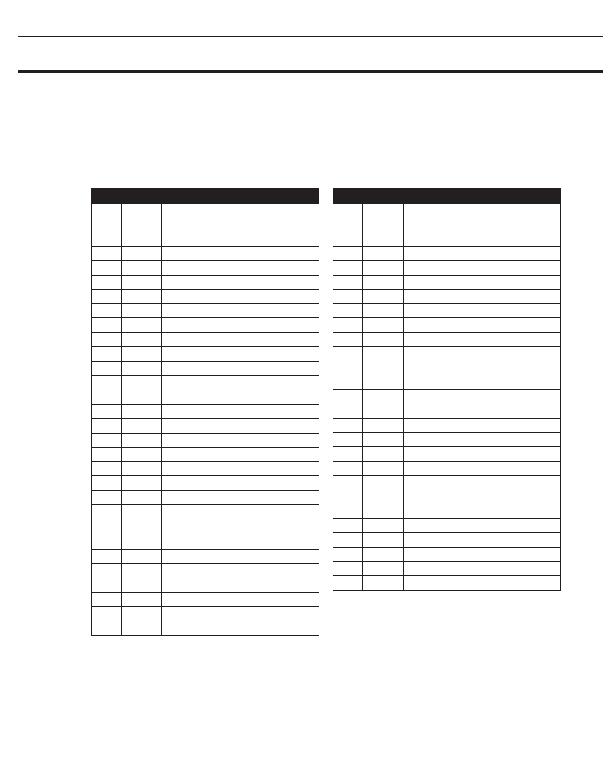
30- Meal (CR3D1XXX1)
Convect-Rite™ III Docking Station Parts List
(See Figures: 4-5 and 4-6)
Installation & Service
Manual
ITEM# PART# DESCRIPTION
*1 98837 anchor, oor,1/2”,3/8”-16
*2 98773 compressor
3 96897 angle bracket
4 96734 blower wheel, cold side
5 96887 blower,wheel, hot side,8.5” dia
6 96768 brass latch, foot pedal
7 98086 caster 4” swivel
8 98087 caster 4” swivel with brake
9 96783 clevis pin,3/8”,5/32” hole,1” lg
10 96943 condensing unit
11 96703 controller N7
12 96702 controller membrane only N7
13 96784 cotter pin,5/32” d,3/4”L
14 96955 cover,perf,cold,return
15 96954 cover,perf,cold,supply
16 96956 cover,perf,hot,return
17 96941 cover,perf,hot,supply
18 96758 dryer
19 96938 eps, vane,cold side
20 98191 evap pan bracket
21 98164 evap pan shroud
22 98117 evaporative pan assy
23 96974 extrusion, gasket,al,hold
24 na na
25 99763 foot pedal cover
26a 98838 foot, oor, tear drop shape
26b 98839 foot, back, round
*27 98190 gasket, interface
28 96742 heater coils for 8.5in dia blower
*29 96937 housing eps
ITEM# PART# DESCRIPTION
*30 96966 insulation, left hot side
*31 96972 insulation, lft fwd hot side
*32 96964 insulation, rear left cold side
*33 96965 insulation, rear mid cold side
*34 96963 insulation, rear right cold side
*35 96968 insulation, right cold side back
*36 96967 insulation, right cold side fwd
37 96728 motor, fan cold side and hot side
38 96898 receiver,copeland,577-0315-02
*39 96156 safe temp thermocouple (white wire)
40 96787 sensor nut,m14x1,260 brass
41 97764 side panel plastic (COLD)
42 97763 side panel plastic (HOT)
43 96759 site glass
44 96756 solenoid
45 96716 switch, on-off with light knob
46 96766 switch,limit,roller plunger,9ft cable
*47 96792 thermocouple (left hand side of pair)
48 96785 thrust bearing,3/8” shft d, 3/4” od,1/8”
49 98073 cap plastic
50 97754 top cover
*51 98127 trim strip left & right
*52 98348 trim strip top
53 97718 valve,thermal expansion (cold)
54 97719 valve,thermal expansion (hot)
55 98076 wall mount bracket
*56 98571 solenoid repair kit
The parts listed above are noted in Figures 4-5 and 4-6 and display the specic location of
each part.
Note: “*” Indicates items not shown in the diagram.
26
FOR SERVICE CALL - ALADDIN TEMP-RITE® - Tech Service 1 (800) 888-5426
30- Meal (CR3D1XXX1)
9
835
13
23
6
24
14
15
16
17
111219
25
28
7
4
50
42
37
40
46
41
454849
Convect-Rite™ III Docking Station Illustration
Figure 4-1
NOTE: Shown without evaporator on right side
FOR SERVICE CALL - ALADDIN TEMP-RITE® - Tech Service 1 (800) 888-5426
27
CONVECT-RITE™ III Docking Stations
10
18
26
21
22
20
43
38
44
54
37
53
55
30- Meal (CR3D1XXX1)
Convect-Rite™ III Docking Station Illustration
Installation & Service
Manual
28
Figure 4-6
FOR SERVICE CALL - ALADDIN TEMP-RITE® - Tech Service 1 (800) 888-5426

TB1
F1-3
CR1
CR3
CR4
CR2
TR1
TH1
F4-5
CB1
CB2
28
30
11
12
10
9
18
17
1
2
3
4
25
31
15
30- Meal (CR3D1XXX1)
Convect-Rite™ III Electrical Layout and Parts List
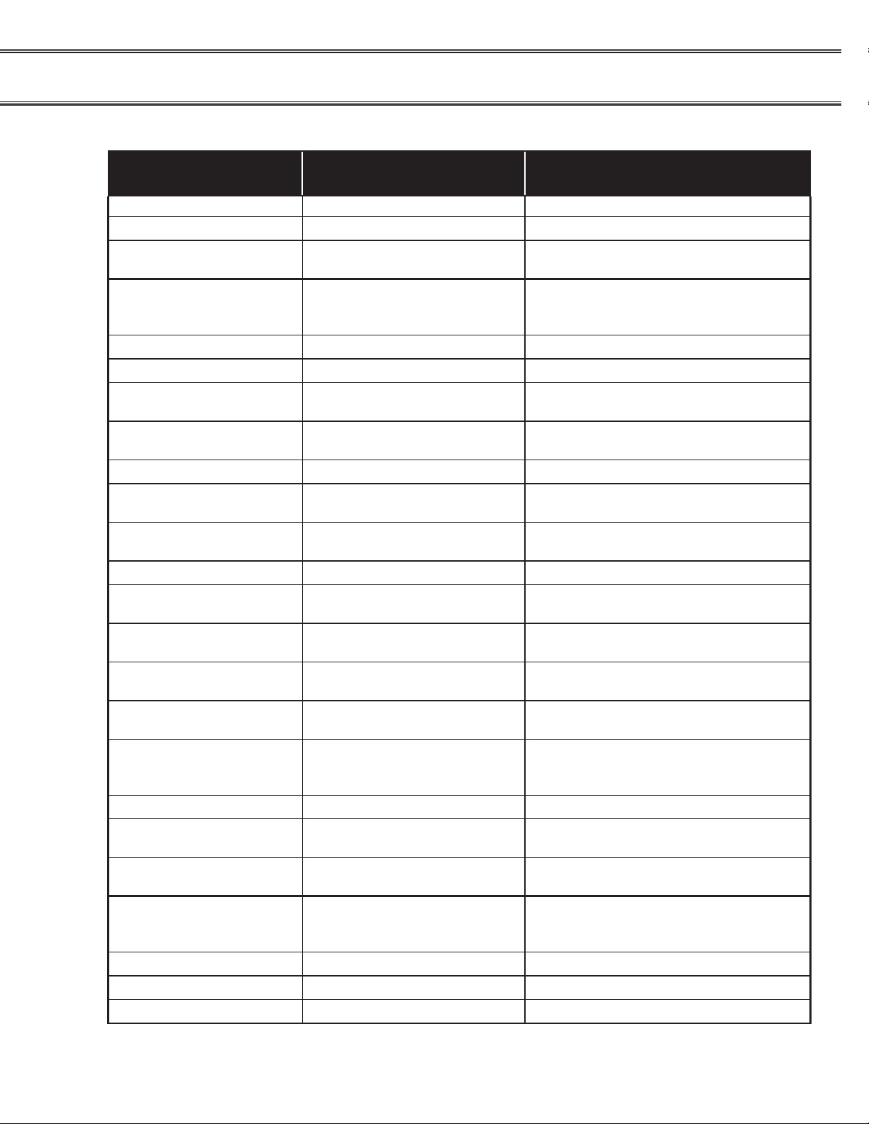
The electrical parts list below notes all “KEY” numbers in the control panel layout and illustrated in Figure 3-3.
KEY QTY SUPPLIER PART NUMBER DESCRIPTION
1 1 Aladdin 96910 Contactor,IEC 9 Amp,208 VAC,4 Pole
2 1 Aladdin 96940 Contactor,IEC 9 Amp,24 VAC,4 Pole
3 1 Aladdin 96911 Contactor,IEC 30 Amp,208 VAC,3 Pole
4 1 Aladdin 98231 Auxiliary Contact Block
*5 2 Aladdin 96913 Jumper,2 Pole
*6 3 Aladdin 96914 Jumper,3 Pole
*7 6 Aladdin 96915 End Anchor,DIN 35mm
*8 5 Aladdin 96916 End Barrier
9 1 Aladdin 96917 Fuse Block,Class CC,3 Pole,600 V,W/Indication
10 1 Aladdin 96918 Fuse Block,Class CC,2 Pole,600 V,W/Indication
11 1 Aladdin 96920 Supplementary Protector,15AMP,3 Pole
12 1 Aladdin 96919 Supplementary Protector, 4AMP,1 Pole
*13 30 Aladdin 96921 Terminal,30 Amp,Gray,600V,22-10 Awg
*14 12 Aladdin 96922 Terminal,30 Amp,Red,600V,22-10 Awg
15 1 Aladdin 96923 Transformer,208V/24V,63VA
*16 3 Aladdin 96924 Terminal,Grounding,22-12 Awg
17 2 Aladdin 96925 Fuse,600V,4 Amp,Class CC
18 3 Aladdin 96926 Fuse,600V,30 Amp,Class CC
*19 1 Allen Bradley 1492-SM6X12V1-10 Terminal Strip Marker,Vertical 1-10
*20 1 Allen Bradley 1492-SM6X12V11-20 Terminal Strip Marker,Vertical 11-20
*21 1 Allen Bradley 1492-SM6X12V21-30 Terminal Strip Marker,Vertical 21-30
*22 1 Allen Bradley 1492-SM6X12V31-40 Terminal Strip Marker,Vertical 31-40
*23 1 Allen Bradley 1492-SM6X12V41-50 Terminal Strip Marker,Vertical 41-50
*24 9 Thomas & Betts C10-10 Ring Terminal,Un-insulated,10-12 Awg,#10
25 1 Aladdin 96927 Contactor,E-Safe,3 Pole,20 Amp,24 Vac Control
25 1 Aladdin 99221 Contactor, E-Safe 2, For SN after J0017-1
*26 1 Molex 43025-1600 Housing,16 Pin Connector
*27 4 Molex 43030-0007 Pin,Femal,Molex
28 1 Square D PK9GTA Ground Bar
*29 1 Acco TS-35 Din Rail,Steel,7x35mm,(1) 12",(1) 7",(1) 6.5"
30 1 Aladdin 96928 Thermostat,15A,250V Contact, 200C Fixed SP
31 1 Quality Ind. Custom Panel
32 A/R Thomas & Betts T1XHDG Wire Duct,1 x 2" Gray
33 A/R Thomas & Betts T1CG Wire Duct Cover,1" Gray
Electrical Parts List
Figure 4-7
FOR SERVICE CALL - ALADDIN TEMP-RITE® - Tech Service 1 (800) 888-5426
29

CONVECT-RITE™ III Docking Stations
Safe-Temp Parts
Installation & Service
Manual
Description
Temperature transmitter (Hot & Cold side) 96151 99139
On/Off switch transmitter 96152 99135
Thermalcouple (Hot & Cold side) 96156 96156
Address label 98315 98315
NOTE: Digital transmitters have blue wire terminals
Analog
Digital
V. OPERATION & PROGRAMMING
The Convect-Rite™ III System is safe and easy to operate. The system uses the most
advanced rethermalization methods available. Please refer to the Owner’s Manual Operating
& Programing section for details on how to operate the Convect-Rite™ III System.
30
FOR SERVICE CALL - ALADDIN TEMP-RITE® - Tech Service 1 (800) 888-5426
VI. PREVENTIVE MAINTENANCE
PREVENTIVE MAINTENANCE AND CLEANING
INTRODUCTION
Maintenance on the Convect-Rite™ III equipment must be performed on a regular basis
to keep the units operating properly. Follow the maintenance instructions in this chapter
and problems will be kept to a minimum. If problems do occur, refer to the Troubleshooting
Guide.
! WARNING !
DEATH, INJURY, OR EQUIPMENT DAMAGE may result from improper service
or maintenance practices. Always turn the main power switch or breaker on the
Docking Station switch to the OFF position on each unit before starting service,
maintenance or repairs.
Convect-Rite™ III Docking Station
Daily
• Clean the exterior of the unit only. As with any other piece of equipment containing
electrical components, it should be cleaned on a regular basis with a wet sponge.
Wipe it dry with a smooth cotton cloth. Avoid the use of abrasive products or chlorides. Do not spray Docking Station with hose or steam wand.
Monthly
• Check and adjust the Docking Station micro limit switches as required.
• Check and tighten all adjustment bolts both at the wall and on the oor.
Biannually
• Remove the black plastic top cover of the Docking Station. Vacuum the
condensing unit coil to remove dust and dirt.
! CAUTION !
Inside and outside front panel of the hot section of the Convect-Rite™ III Docking
Station stays hot for a short period of time after rethermalization; allow 15 minutes for
cool-down before cleaning.
FOR SERVICE CALL - ALADDIN TEMP-RITE® - Tech Service 1 (800) 888-5426
31

CONVECT-RITE™ III Docking Stations
Cleaning of plastic top and side panels:
NOTE: It is extremely important to read the following instructions for cleaning plastic
ancillary equipment.
• It is sufcient to wipe the plastic components of the Convect-Rite™ III Docking
Station with a soft cloth using warm water (Not to Exceed 140°F/60°C) to which
has been added diluted detergent; the detergent used must have a low alkaline
value and contain a very low percentage of caustic soda. The detergent must not
exceed the dilution rate recommended by the supplier.
• After cleaning these components, wipe down with a soft cloth using clear water.
• Make sure that all plastic components are thoroughly dried before using.
• Manufacturer accepts no responsibility if the above instructions are not strictly
adhered to.
Installation & Service
Manual
32
FOR SERVICE CALL - ALADDIN TEMP-RITE® - Tech Service 1 (800) 888-5426
OPERATOR’S TROUBLESHOOTING GUIDE FOR OPERATIONAL SAFETY
! WARNING !
DEATH, INJURY, OR SHOCK can occur by touching electrical components
and wires inside the Docking Station when the main power switch is in the ON
position.
NEVER REMOVE THE PLASTIC TOP OR SERVICE ACCESS PANELS of
the Docking Station while main power switch is in the ON position. Allow only
authorized factory trained service representatives to perform service, maintenance and repairs that require the removal of any plastic top or service access
panels.
This troubleshooting guide includes a list of conditions that may be encountered during rou-
tine operation and maintenance. The rst column on the left describes these symptoms. The
second column in the middle lists the causes for the conditions listed in column one. The third
column on the right lists remedies and/or references for the conditions and causes in columns
one and two.
DO NOT TRY to correct the condition that requires an authorized service representative as
this may adversely affect the warranty coverage.
TROUBLESHOOTING NOTES
1. If problem is inside the Docking Station, call the Aladdin Temp-Rite® Service
Department at 1-800-888-5426. Aladdin will not pay for warranty repairs by
unauthorized repair centers.
2. Repairs to external wiring should be done by a Licensed Electrician.
3. Proper installation of the Convect-Rite™ III Docking Station is the responsibility of the owner or installer.
4. Repairs to external plumbing (if required) should be done by a Licensed mechanical contractor.
5. Repairs to compressor-condensing unit should be done by a Licensed
Refrigeration Engineer.
FOR SERVICE CALL - ALADDIN TEMP-RITE® - Tech Service 1 (800) 888-5426
33

CONVECT-RITE™ III Docking Stations
Condition is occurring
when: Condition/symptom: Solutions and things to check:
Leveling feet hit thresholds and
Moving the Docking Station
other oor imperfections. Raise feet to full up positions.
Installation & Service
Manual
Use ramp to roll dock over obstruction
Casters do not roll
Installing the Docking
Station.
Engaging the cart to the
Docking Station.
Loading trays Tray does not slide in slot
Shutting doors Doors on cart won’t close Tray not completely pushed in
Keeping cart door open Door not engaged in detent latch Push door completely to the side of the cart
Engaging cart to Docking
Station Cart doesn’t engage Check that dockside door is open
Leveling feet will not lower or
raise. Unlock 7/8” jam nut
Leveling feet will not reach wall
due to wall imperfections.
Wall CANNOT take Docking
force of 550 lbs.
Gap exist between cart and dock
when cart is engaged. Adjust appropriate feet to close gap
Cart does not depress one or
both switches
Docking Station rolls or creeps in
location over time. Check that dock is not resting on casters.
Check that lock is not depressed on either
front caster.
Adjust feet by turning 7/8” nut
Check that black tube caps are not in the
tube.
Securely fasten a 2”X8”X4’ wood board to
the wall to close gap between leveling feet
and wall.
Securely fasten a 2”X8”X4’ wood board to
the wall to distribute force.
Check that the dock is parallel to cart
interface.
Adjust one or both bolts that move latches
from front to back
Use oor mounting brackets to secure front
leveling feet.
Check that leveling feet have rubber grips.
Check that the tray is not warped or
damaged
Divider bar may be present
Check latch and door alignment
Check gasket t
(270°)
Check that door at hinge is completely
seated
Check that no debris is around detent latch
Check that dock is secured against the wall
Check that dock is level
34
FOR SERVICE CALL - ALADDIN TEMP-RITE® - Tech Service 1 (800) 888-5426
Condition is occurring
when: Condition/symptom: Solutions and things to check:
Check that the optional safety doors on the
Docking Station are not closed
Check that the side of the cart with the
locking casters is facing away from the
dock
Check that the dock is at the appropriate
height for the cart
Check micro switch position (see section III
Chill Down
Cold holding overnight
Doesn’t show cart engaged
Cart engaged--compressor
hums, but does not start up
Cart engaged--compressor does
not hum and does not start up
Cart engaged but evaporator
fans do not turn on
Unit does not chill down (reach
programmed settings) in one
hour
Compressor does not cycle off in
one hour
A signicant amount of water
appears on oor the following
morning
for location)
Check “on/off” switch
Check safety switches
Check unit breaker in control panel
Check all wiring is properly seated
Check plug or junction box
Contact ATR technical service representative
Contact ATR technical service representative
Check component(s) electrical contractor
Check that cart doors are completely
closed
Make sure doors are adjusted to prevent
air leak around doors
Check that there is no air leak between
dock and cart
Initial temperature of food may be too high
Make sure ambient air temperature is less
than 85 degrees F.
Check that cart doors are completely
closed
Make sure doors are adjusted to prevent
air leak around doors
Check that there is no air leak between
dock and cart
Check condenser for proper spacing and
air ventilation
Check that water in evaporator drain tubes
drains into condensate pans
FOR SERVICE CALL - ALADDIN TEMP-RITE® - Tech Service 1 (800) 888-5426
35

CONVECT-RITE™ III Docking Stations
Condition is occurring
when: Condition/symptom: Solutions and things to check:
Evaporator has frost exceeding
10% of coil
Rethermalization Cycle Does not start Retherm cycle
Retherm cycle is too long/short Check meal setting in program
Unit does not reach retherm temperature setting at end of cycle
and hot food temperature is NOT
acceptable
Heater element(s) do not get hot Check components) electrical contractor
Equalization Cycle Does not start Equalization
Equalization cycle is too long/
short
Installation & Service
Manual
Check the connection between the
condensate evaporating pans to insure it is
not clogged.
Check any air leaks between cart and dock
Check that evap pans are getting hot.
Check any air leaks around cart doors
Defrost occurrence and duration is not
often or long enough. Adjust as necessary
to eliminated condition.
Check any air leaks between cart and dock
Check any air leaks around cart doors
Check that automatic programmed start
time window has not passed
Check that controller is in automatic or
manual retherm mode
Check time AM-PM
Check time of meal settings
Wrong meal may have been selected in
manual mode
Cart was disengaged too soon or during
cycle
Slots in cart center panel may be missing
tray(s) or divider bar(s))
Check that all fans are turning
One or more heater elements may not be
functioning.
Check any air leaks between cart and dock
Check any air leaks around cart doors
Check that Equalization time is programmed
Adjust Equalization cycle temperature
setting(s) and duration(s)
36
Hold Cycle after Equalization Does not start Hold Check that Hold time is programmed
Adjust Hold cycle temperature setting(s)
Hold cycle is too long/short
and duration(s)
FOR SERVICE CALL - ALADDIN TEMP-RITE® - Tech Service 1 (800) 888-5426
Condition is occurring
when: Condition/symptom: Solutions and things to check:
Disengaging cart Cart will not disengage Depress either foot pedal release
Check cart caster locks
Hot food temperatures
Cold food temperatures
Dock continues to run when cart
is disengaged
Hot food temperatures not hot
enough after retherm and equalization
Hot food temperatures too hot
after retherm and equalization
Hot food temperatures have
more than 20°F difference from
tray to tray
Cold food temperatures not cold
enough after one hour of Chill
down cycle Check any air leaks between cart and dock
Check that micro switch is not sticking
closed
Check Retherm/Equalization cycle temperature setting(s) and duration(s)
Check any air leaks between cart and dock
Check any air leaks around cart doors
Slots in cart center panel may be missing
tray(s) or divider bar(s)
Inappropriate entrée dome, mug & soup
bowl may be in use
Check that all fans are turning
One or more heater elements may not be
functioning.
Wrong meal may have been selected in
Manual mode
Adjust temperature setting and tolerance
Wrong meal may have been selected in
Manual mode
Inappropriate entrée dome, mug & soup
bowl may be in use
Adjust Retherm/Equalization cycle temperature setting(s) and duration(s)
Food input temperature may have been too
high.
slots in cart center panel may be missing
tray(s) or divider bar(s)
Check that all fans are turning
Check for presence of air deectors inside
the supply plenum on the cart
One or more heater elements may not be
functioning.
Check any air leaks around cart doors
Check that all fans are turning
Check to see if compressor is running
FOR SERVICE CALL - ALADDIN TEMP-RITE® - Tech Service 1 (800) 888-5426
37

CONVECT-RITE™ III Docking Stations
Condition is occurring
when: Condition/symptom: Solutions and things to check:
Installation & Service
Manual
Check to see if system is generating cold
air (possible refrigerant leak)
Adjust temperature setting and tolerance
Cold food temperatures have
more than 5°F difference from
tray to tray
Controller Display Improper temperature units Check program for proper unit - °C or °F
Check that all fans are turning
Check for presence of air deectors inside
the supply plenum on the cart
Slots in cart center panel may be missing
tray(s) or divider bar(s)
38
FOR SERVICE CALL - ALADDIN TEMP-RITE® - Tech Service 1 (800) 888-5426

SERVICING PROCEDURES
FOR SERVICE ACCESS:
Adjust the four feet on the base of the Docking Station, lower the unit onto the casters.
Remove oor brackets. Pull unit away from the wall and turn 90°-180° for ease of
service.
MOTOR, HOT SIDE
1. See “FOR SERVICE ACCESS” then remove the bolts from the back ange, - slide the
cover back, slightly rotating it towards yourself; - pull the panel towards yourself. (Only
the back ange is bolted onto the frame; the front ange slides onto studs)
2. Disconnect wiring for the failed motor. (Time-saving tip: splice the wiring of new motor
into existing wiring)
3. Remove the perforated plates from the front of the unit and then remove the orice
plate. Mark the location of the blower on the shaft.
4. Remove the front part of the shroud, and then loosen the blower wheel mounted to the
shaft of the failed motor to easily slide it off.
5. Remove the motor mount bracket with the failed motor still mounted on it.
6. Replace the failed motor, and attach it to the motor mount bracket using (4) 10-32
nylock nuts and (4) #10 at washers with the capacitor mounted toward the left of the
bracket and back of the dock.
7. Place the motor mount bracket against the rails and locate it using (4) ¼-20 bolts and
(4) ¼” at washers. Center the motor shaft inside the housing hole and then tighten the
bolts down.
8. Attach the fan blower wheel to the shaft of the motor and slide down so it is set at the
depth on the shaft marked previously. Tighten setscrew on the “FLATS” of the shaft.
9. Reattach all removed components.
MOTOR, COLD SIDE
1. See “FOR SERVICE ACCESS”, slide forward, and oor, slide forward, and remove
back cover and right side panel.
2. Remove the right side panel: - remove the bolts from the back ange, -slide panel back,
slightly rotating it towards yourself; - pull panel towards yourself. (Only the back ange
is bolted onto the frame; the front ange slides onto studs)
FOR SERVICE CALL - ALADDIN TEMP-RITE® - Tech Service 1 (800) 888-5426
39

CONVECT-RITE™ III Docking Stations
3. Disconnect wiring for the failed motor. (Time-saving tip: splice the wiring of new motor
into existing wiring)
4. Remove the control panel, housing side cover and EPS vane.
5. Mark the location of the blower on the shaft and then loosen setscrew on the blower
wheel so it can slide off the shaft.
6. Remove the motor mount bracket with failed motor still mounted on it.
7. Replace the failed motor, and attach it to the motor mount bracket using 10-32 nylock
nuts and #10 at washers with the capacitor mounted towards the top of the bracket.
8. Place the motor mount bracket against the rails and locate it using (4) ¼-20 bolts and
(4) ¼” at washers. Center the motor shaft inside the housing hole and then tighten the
bolts down.
9. Attach the fan blower wheel to the shaft of the motor and slide down so it is set at the
depth on the shaft marked previously. Tighten setscrew on the “FLATS” of the shaft.
Installation & Service
Manual
10. Reattach all removed components
HEATERS
1. Remove left side panel: - remove the bolts from the back ange, -slide the panel back,
slightly rotating it towards yourself; - pull the panel towards yourself. (Only the back
ange is bolted onto the frame; the front ange slides onto studs)
2. Disconnect the wiring for the failed heater.
3. Remove the perforated plates from the front of the unit and then remove the orice
plate. Mark the location of the blower on the shaft.
4. Remove front part of the shroud, and then loosen the blower wheel mounted to the shaft
of the motor so you can easily slide it off.
5. Replace the failed heater and rectangular silicone insulator. Be careful to attach the
wires to the same terminal locations.
6. Attach the fan blower wheel to the shaft of the motor and slide down so it is set at a
depth on the shaft marked previously. Tighten setscrew on the “FLATS” of the shaft.
40
7. Reattach all removed components.
FOR SERVICE CALL - ALADDIN TEMP-RITE® - Tech Service 1 (800) 888-5426

GASKET
1. Remove damaged gasket.
2. Obtain a new gasket and install the corners or ends rst, and then continue towards
the center, spreading gasket uniformly so no buckling occurs.
LIMIT SWITCH
1. Remove right side panel: - remove the bolts from the back ange, -slide the panel back,
slightly rotating it towards yourself; - pull the panel towards yourself. (Only the back
ange is bolted onto the frame; the front ange slides onto studs)
2. Disconnect the limit switch wiring.
3. Remove protective brass nut from the front of failed limit switch.
4. Remove thin nut and pull failed switch out.
5. Obtain new limit switch and install it onto the base bracket. Locate and secure the
switch with thin nuts that come with the switch and tighten down completely with
protective brass nut. Make sure that new limit switch extends to the same level as
existing one.
6. Connect wiring and reattach all removed components
7. Dock cart to check engagement. Adjust the limit switch accordingly.
EVAPORATIVE PAN
1. Remove right side panel: - remove the bolts from the back ange, -slide the panel back,
slightly rotating it towards yourself; - pull the panel towards yourself. (Only the back
ange is bolted onto the frame; the front ange slides onto studs)
2. Disconnect failed evaporative pan wiring.
3. Remove evap pan bracket.
4. Replace the pans and install new pans, making sure that drain piping goes inside the
pans.
5. Replace evap pan bracket.
6. Connect wiring and reattach removed components.
FOR SERVICE CALL - ALADDIN TEMP-RITE® - Tech Service 1 (800) 888-5426
41

CONVECT-RITE™ III Docking Stations
REPAIRING THE REFRIGERATION SYSTEM
PUMP DOWN
1. Close the receiver outlet valve and operate the compressor until the suction pressure
gauge levels off to 3-5 psi.
2. Close the receiver valve and stop the compressor.
3. The system can now be opened for repair.
LEAK CHECKING
1. Once a repair has been made, pressurize and leak test the entire system including the
condensing unit, evaporator, and all connecting tubing, ttings, and brazed joints using
the intended operating refrigerant for leak testing.
Installation & Service
Manual
2. DO NOT USE OXYGEN OR COMBUSTIBLE GASES FOR LEAK TESTING.
3. A pressure equal to the low side test pressure marked on the unit nameplate is
recommended for leak testing.
4. Again, repair any leaks found.
EVACUATION
1. Connect a vacuum pump to both the low and high side evacuation valves with copper
tube or high vacuum tube (3/8” ID MIN.) and draw a deep vacuum of at least 1500
microns.
2. DO NOT USE THE MOTOR-COMPRESSOR TO PULL A VACUUM.
3. DO NOT OPERATE THE MOTOR-COMPRESSOR IN A VACUUM.
4. Break the vacuum with nitrogen.
5. Evacuate the system to hold at 500 microns and break the vacuum with refrigerant.
6. Remove the vacuum pump.
42
7. The system is now ready for charging.
FOR SERVICE CALL - ALADDIN TEMP-RITE® - Tech Service 1 (800) 888-5426

CHARGING
1. Charge the system with the correct amount of refrigerant as listed on the data
nameplate on the right hand side of the unit.
2. DO NOT CHARGE THE UNIT BY THE SITE GLASS LOCATED ON THE
CONDENSING UNIT.
3. BE SURE NOT TO OVERCHARGE THE UNIT. AN OVERCHARGE MIGHT PERMIT
LIQUID REFRIGERANT TO ENTER THE MOTOR-COMPRESSOR AND DAMAGE
THE VALVES, RODS, PISTONS, ETC.
4. Make sure all are caps and valve caps are tight.
NORMAL OPERATING CONDITIONS FOR BOTH 24 AND 30 MEAL Docking Stations
These are the operating temperatures and pressures for both the 24 and 30 meal models
JUST BEFORE THE COMPRESSOR CYCLES OFF:
TEV Open Lo Pressure Lo Temp Super Heat Temp
Both 55-60psi 25-35°F 3-15°F
Cold Only 45-50psi 25-35°F 3-15°F
Hot Only 50-55psi 25-35°F 3-15°F
TEV Open Hi Pressure Hi Temp Subcooling
Both 250psi 90-100°F 5-10°F
Cold Only 240psi 90-100°F 5-10°F
Hot Only 245psi 90-100°F 5-10°F
FOR SERVICE CALL - ALADDIN TEMP-RITE® - Tech Service 1 (800) 888-5426
43
CONVECT-RITE™ III Docking Stations
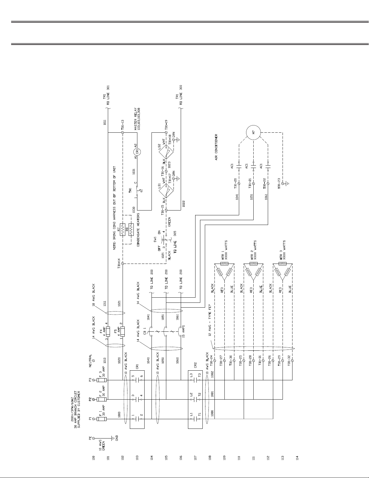
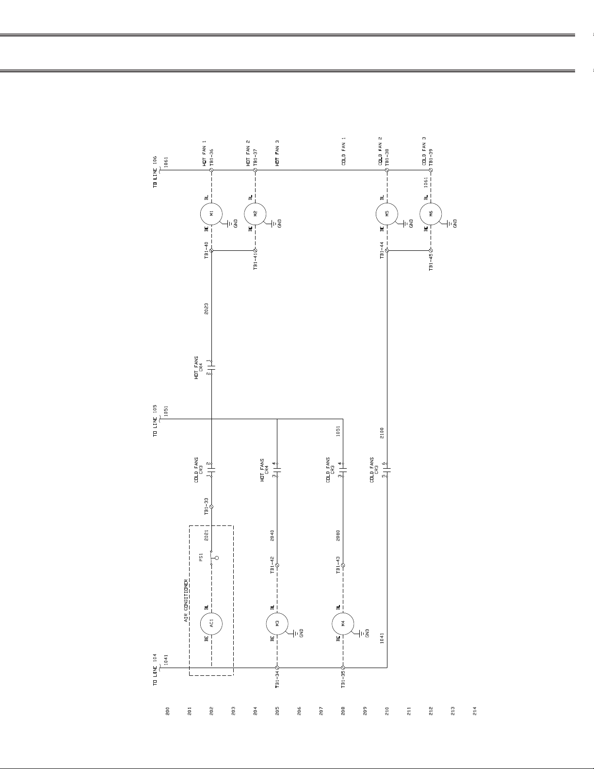
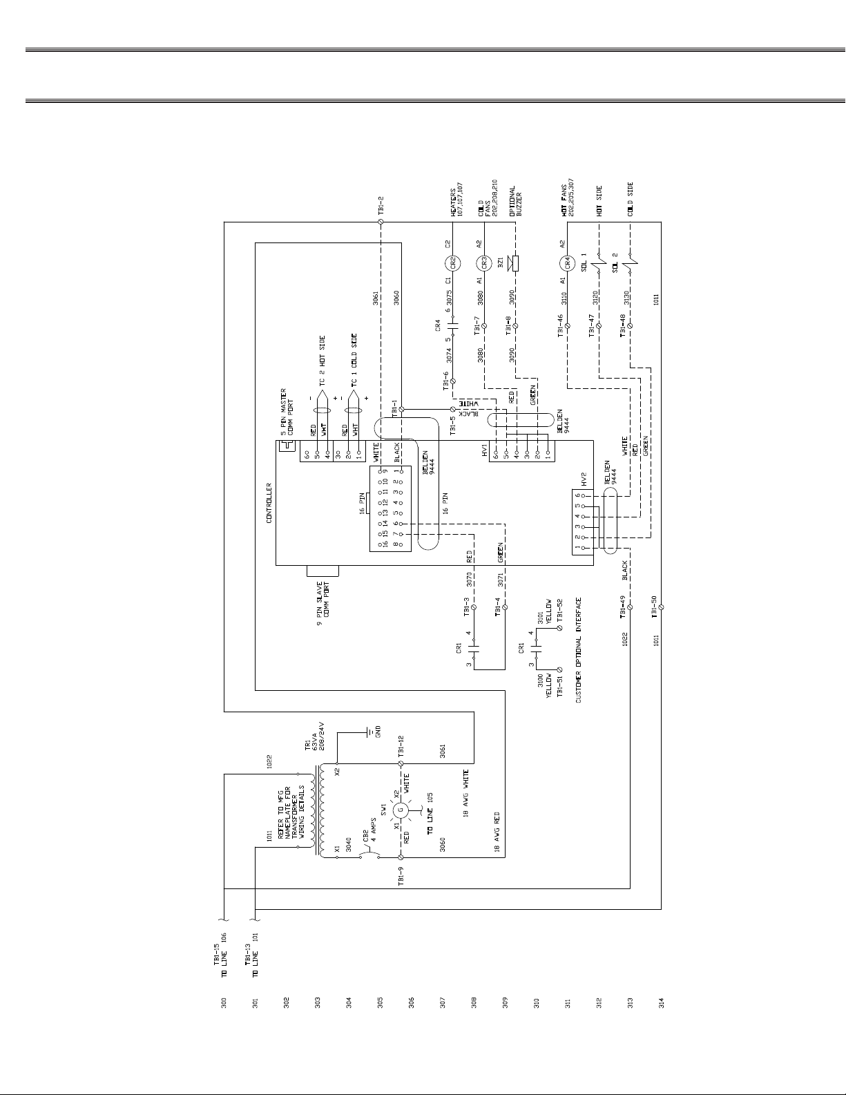
Wiring Diagrams
24 Meal (CR3D0XXX1)
Installation & Service
Manual
44
FOR SERVICE CALL - ALADDIN TEMP-RITE® - Tech Service 1 (800) 888-5426
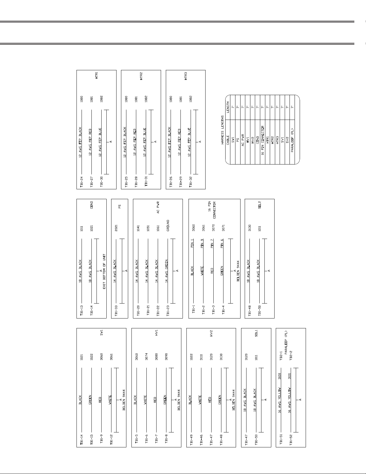
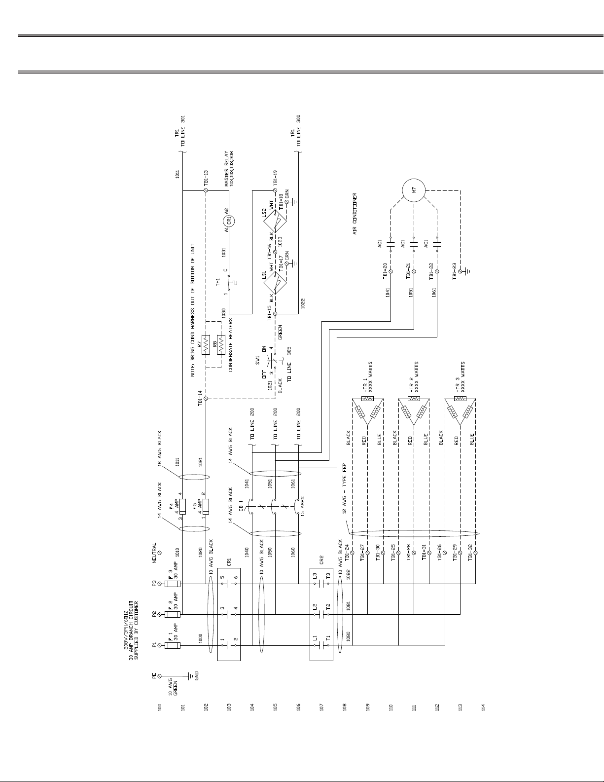
24 Meal (CR3D0XXX1)
FOR SERVICE CALL - ALADDIN TEMP-RITE® - Tech Service 1 (800) 888-5426
45
CONVECT-RITE™ III Docking Stations
24 Meal (CR3D0XXX1)
Installation & Service
Manual
46
FOR SERVICE CALL - ALADDIN TEMP-RITE® - Tech Service 1 (800) 888-5426
24 Meal (CR3D0XXX1)
FOR SERVICE CALL - ALADDIN TEMP-RITE® - Tech Service 1 (800) 888-5426
47
CONVECT-RITE™ III Docking Stations
30 Meal (CR3D1XXX1)
Installation & Service
Manual
48
FOR SERVICE CALL - ALADDIN TEMP-RITE® - Tech Service 1 (800) 888-5426

30 Meal (CR3D1XXX1)
FOR SERVICE CALL - ALADDIN TEMP-RITE® - Tech Service 1 (800) 888-5426
49

CONVECT-RITE™ III Docking Stations
30 Meal (CR3D1XXX1)
Installation & Service
Manual
50
FOR SERVICE CALL - ALADDIN TEMP-RITE® - Tech Service 1 (800) 888-5426

30 Meal (CR3D1XXX1)
FOR SERVICE CALL - ALADDIN TEMP-RITE® - Tech Service 1 (800) 888-5426
51

CONVECT-RITE™ III Docking Stations
Installation & Service
Manual
VII. WARRANTY
ALADDIN TEMP-RITE
EQUIPMENT
LIMITED WARRANTY
Effective March 24, 2004
Aladdin Temp-Rite (“ATR”) warrants to the original purchaser that the equipment listed below shall be free from defects
in material and workmanship under normal use for the applicable warranty term set forth below. ATR’s obligation under
this warranty is limited to the repair or replacement , at the sole option of ATR, of any part which upon inspection and
examination by ATR or its authorized agent is found to be defective. A written description detailing the nature of the claimed
defect, together with the equipment claimed to be defective if required by ATR, must be delivered to ATR or its authorized
agent within 30 days of discovery of the claimed defect (but in no event later than 30 days after the expiration of the
applicable warranty term).
CONVECT-RITE™III
EQUIPMENT*
WARRANTY
TERMS*
COMPRESSOR
WARRANTY TERM*
PARTS ONLY**
PARTS LABOR
CONVECT-RITE™ III DOCKING STATION 1 Year 1 Year 5 Years
CONVECT-RITE™ III DOCKING STATION HEATING ELEMENTS
*The warranty term commences 30 days after the date of ATR’s invoice for the equipment. All our reusable crockery such
as: plates, dishes, bowls, covers are not included in our manufactures equipment warranty.
**The compressor warranty covers the compressor only and does not include any shipping charges, other transportation
costs, any external parts or electrical components, labor, refrigerants and taxes. Max 85°F Ambient operating environment.
THE WARRANTIES AND REPRESENTATIONS OF ATR CONTAINED HEREIN ARE EXPRESSLY IN LIEU OF, AND THE
BUYER WAIVES, ANY AND ALL OTHER WARRANTIES EXPRESS OR IMPLIED, INCLUDING THE WARRANTIES OF
MERCHANTABILITY AND FITNESS FOR A PARTICULAR PURPOSE, AND ANY OTHER REMEDIES AGAINST ATR,
WHETHER BASED UPON CONTRACT, NEGLIGENCE, STRICT LIABILITY OR OTHERWISE. ATR SHALL NOT BE
LIABLE FOR ANY CONSEQUENTIAL OR INCIDENTAL DAMAGES OR ECONOMIC LOSS OF ANY NATURE (INCLUDING
WITHOUT LIMITATION LOSS OF REVENUES AND/OR PROFITS) THAT MAY BE CLAIMED TO RESULT FROM ANY
NEGLIGENCE OR BREACH OF WARRANTY OR CONTRACT BY ATR.
Exceptions and Exclusions
This warranty is issued only to the original purchaser, and is not transferable and applies only to the products installed
within the United States of America, its territories and Canada. During the term of any labor warranty, ATR will pay all
pre-approved shipping charges incurred in returning defective equipment to ATR and labor costs incurred in the removal
and reinstallation of such equipment. Contact ATR before returning any defective equipment or other wise performing any
warranty repairs. ATR assumes no liability for any work or repair performed without its prior approval. After the expiration
of any labor warranty, the original purchaser is responsible for all shipping charges incurred in returning defective equipment
to ATR and labor for removing and reinstalling such equipment. ATR shall not be responsible for the replacement of
expendable items like lamps and fuses or product failure resulting from normal wear and tear, improper installation, misuse,
sabotage, abuse, neglect, accident, unauthorized alterations to repair, or other factors beyond the control of ATR. Neither
this warranty, not the liability of ATR may be modied or extended by action of any agent, distributor or other person or by
custom or practice.
2 Years
1 Year na
CALL ATR TOLL FREE AT 1-800-888-5426 IF YOU HAVE ANY QUESTIONS ABOUT THIS WARRANTY OR YOUR ATR
PRODUCT.
52
FOR SERVICE CALL - ALADDIN TEMP-RITE® - Tech Service 1 (800) 888-5426
 Loading...