

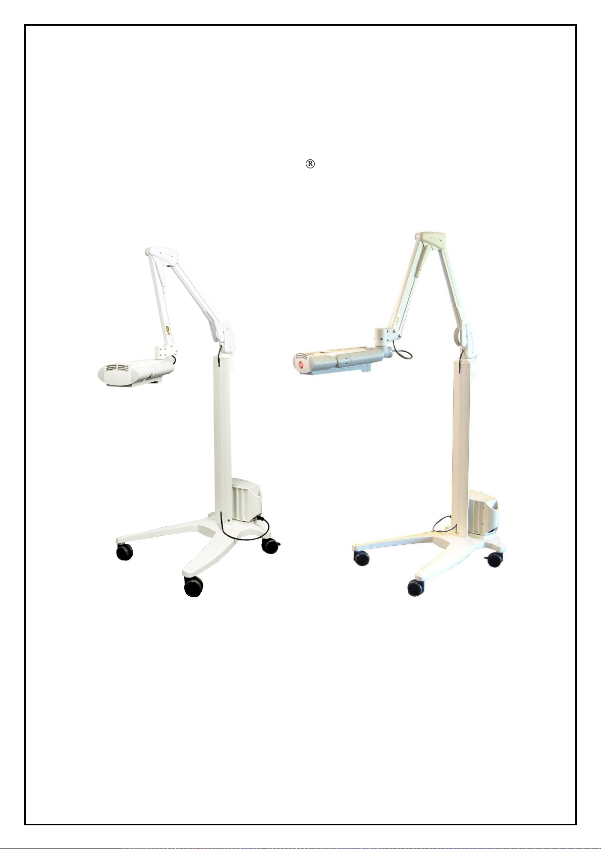
Aktilite CL128 User manual
SERVICE MANUAL
Aktilite
Ver 1.
CL128
3
Photoc
Hoffsveien 48
NO-
0377 OSLO, Norway
Phone: +47 22 06 22 10
www.photocure.com
ure ASA

Service Manual Aktilite
SERVICE
MANUAL
Aktilite
Any kind of service should only be carried out by authorised personnel.
Refer
to the User Manual for further information regarding safety and precautions.
TABLE OF CONTENTS
1
ASSEMBLY OF AKTILITE
1.1 M
1.1.1 Tools needed for the assembly of lamp with fixed lamp head................................3
1.1.2
1.2 R
1.3 HO
1.4 L
1.5 G
1.6 P
1.6.1
1.6.2
1.7 H
1.8 H
1.9 L
1.9.1
1.9.2
1.9.3
1.10 S
1.11 L
1.11.1
1.11.2
1.12 P
1.12.1
1.12.2
1.13 L
ATERIAL/EQUIPMENT..................................................................................................
Tools need
EADY TESTED SYSTEM ELECTRONICS MODULE
USING TOP MODULE
IGHT MODULE
LUE LENSES .................................................................................................................
OSITIONING ARM MODUL
Fixed lamp head .....................................................................................................
Detachable lamp head............................................................................................
OUSING BOTTOM MODULE
OUSING BACK MODULE
AMP HEAD MODULE
Fixed lamp head ...................................................................................................10
Detachable lamp head..........................................................................................11
Disassemly and Assembly of the lamp
TOP BLOCK MODULE (TS1
AMP INCLUDING PARALL
Fixed lamp head (128
Detachable lamp head (128
ARALLEL ARM WITH LAM
Fixed lamp head (128
Detachable lamp head (128
ABELS PLACEMENT DESC
CL128 LAMP WITH PAR
ed for the assembly of lamp with detachable lamp head ......................
(128
-0-
610)
ASSEMBLY .............................................................
(128
-0-
750) ..........................................................................................
E
(128
-0-
400)
ASSEMBLY ......................................................
(128
-0-
820) .......................................................................
(128
-0-
810)
ASSEMBLY ..........................................................
(128
-0-
200)
ASSEMBLY..............................................................10
-0-
250)
ASSEMBLY ............................................................27
EL ARM ASSEMBLY...............................................................28
-0-
250)...............................................................................28
-0-
252)......................................................................29
P HEAD HOLDER UNIT A
-0-
210)...............................................................................31
-0-
212)......................................................................32
RIPTION ...............................................................................33
CL128
CL128
slide series............................................12
ALLEL ARM.....................
(128
-0-
439)
ASSEMBLY.....................
SSEMBLY ........................................31
3
3
3
4
5
6
6
7
7
8
9
9
2 REPLACING THE DC POW
3
ASSEMBLY OF AKTILITE
3.1 M
3.2
3.3
3.4
3.5 P
4
ERROR CO
Version 1.
ATERIAL/EQUIPMENT................................................................................................35
PS
ELECTRONICS MODULE
PS
HOUSING MODULE
PS
HOUSING MODULE
OWER SUPPLY
DES ..............................................................................................................40
3
(128
-0-
A
B
300)
(128
(128
ER PLUG.......................................................................34
CL128 POWER SUPPLY.............................................35
(128
-0-
330)
ASSEMBLY......................................................36
-0-
310)
ASSEMBLY..........................................................37
-0-
320)
ASSEMBLY..........................................................38
ASSEMBLY.......................................................................39
Page 2 of 41

This service manual is primarily meant for mechanical repairs
with fixed and deta
The electronic control board in the lamp head has to be programmed with the parameters
calibrated light module. If the electronic control board is faulty then the complete board is changed and
programmed with the original p
Device History Record for the lamp kept at the factory
mode can only be done by trained service personnel. The
and lenses.
If a power supply
Photocure. However, this has to be tested for leakage current,
test by qualified personnel.
1
1.1 Material/Equipment
Assembly of Aktilite CL128 Lamp with Parallel Arm
If a led diode is faulty then the complete
chable lamp head.
electronics board
Service Manual Aktilite
arameters for the light module. These
is faulty, a new tested power supply can be obtained from
CL128
and entering the device factory programming
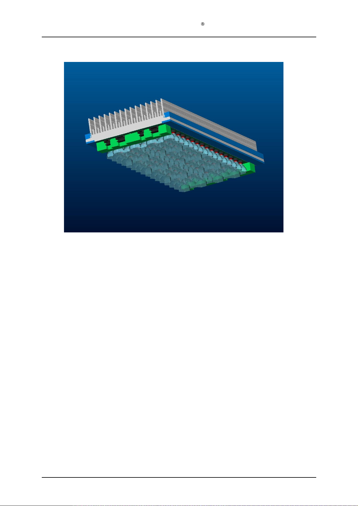
light module consist of led arra
light module
and covers both Aktilite
can
only
be retrieved from the
is changed.
eart
h continuity and withstanding voltage
CL128 lamps
to match
ys, heat sink
the
1.1.1 Tools needed for the assembly of lamp with fixed lamp head
Required tools
# of
items
1
1
1
1
1
1.1.2 Tools needed for the assembly of lamp with detachable lamp head
Required tools
# of
items
1
1
1
1
1
1
1
1
1
1
1
Description
Screwdriver,
Screwdriver, Pozidrive 2
Screwdriver, Torx
Screwdriver, Torx
Screwdriver, Torx T 20
Description
Screwdriver, Pozidrive 1
Screwdriver, Pozidrive 2
Screwdriver, Torx T 10
Screwdriver, Torx T 15
Screwdriver, Torx T 20
Allen key, 5mm
Press nut tool
Crimping tool LEMO DPC.91-701V
Locator male DCE.91.135.BVC
Locator female DCE.91.130.BVM
Ex
traction tool LEMO DCF.91.133.5LT
Pozidrive 1
T 7
T 10
Umbraco
Version 1.
3
Page 3 of 41
Service Manual Aktilite
1.2 Ready Tested System
Electronics
Module
CL128
(128
-0-
439
) assembly
Version 1.
3
Page 4 of 41
Service Manual Aktilite
1.3 Housing top module (128
Required items
Part #
128
-0-
978
1
128
-1-
637
1
128
-1-
932
5
128
-1-
626
1
128
-1-
628
1
128
-1-
931
4
128
-1-
636
1
# of items
CL128
-0-
610) assembly
Description
Housing top (mould
Housing top slide bearing
Screw
Housing right (moulded plastic)
Housing left (moulded plastic)
Screw
User interface (foil keyboard w/ta
Rubbing alcohol (fat free)
PT4x16 countersunk
PT4x25
ed plastic)
il)
Version 1.
Assembly description
Step 1)
Assemble the housing top slide bearing (128
the five countersunk PT4x16 screws (128
Step 2)
Assemble the housing left (128
(128
-0-
978) using the four PT4x25 screws (128
Step 3)
Clean the recessed area at the top of the housing top (128
alcohol
Step 4)
Glue the Key Touch panel (128
3
-1-
637) to the housing top (128
-1-
932).
-1-
628) and housing right (128
-1-
931).
-1-
636) to the housing top (128
-1-
626) to the housing top
-0-
978) using a cloth and rubbing
-0-
978).
-0-
978) using
Page 5 of 41
1.4 Ligh
t module (128
Service Manual Aktilite
-0-
750)
CL128
This light module comes as a ready
control electronics
the documentation f
comprehensive tests has to be done with spectrometer and radiometer so this can only
be done at the factory. The dose factor is a factor that is a combination of wavelength
and irradiance and will vary slightly from light modu
1.5 Glue lenses
If one of the lenses is loose they can be glued on to the substrate using
glue
.
and currents
ollowing
the specific light module. To determine the dose factor,
tested and
(set in factoring mode) has to be adjusted according to
calibrated part. The dose factor in the
le to light module.
Loctite 435
Version 1.
3
Page 6 of 41
Service Manual Aktilite
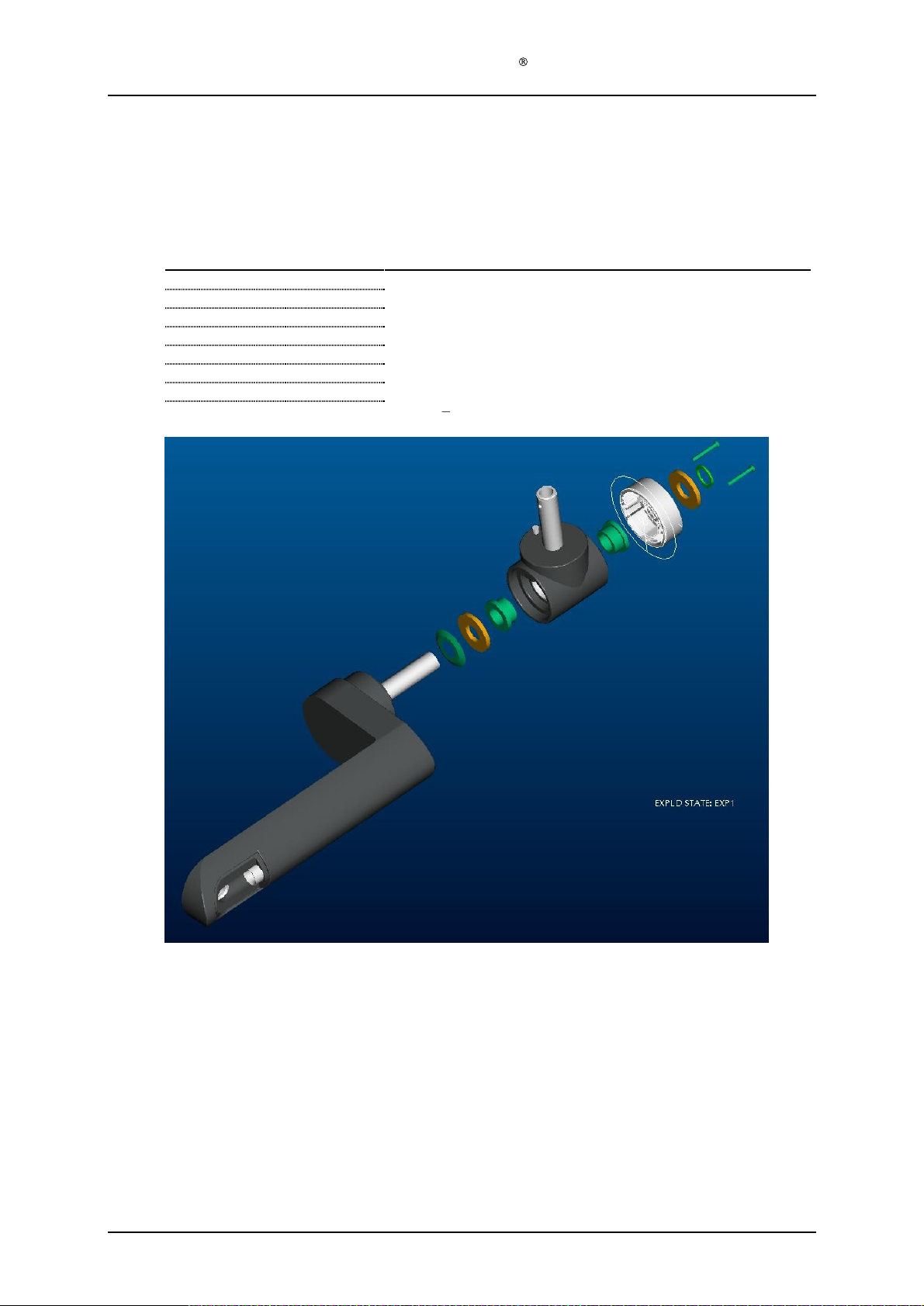
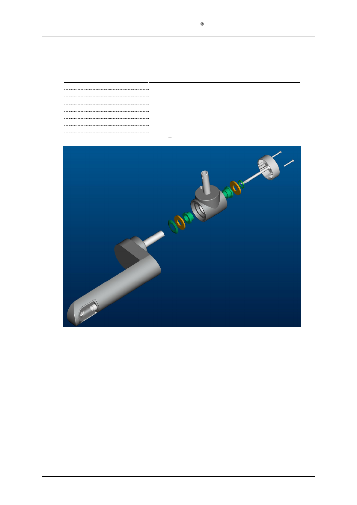
1.6 Positioning arm module (128
1.6.1
F
ixed lamp head
Required items
Part #
128
-0-437 1 T-piece (Moulded plastic)
128
-1-
910
2
128
-0-
428
1
128
-1-
914
2
128
-1-
912
1
128
-1-
916
1
128
-1-
424
1 T-
128
-1-
926
2
# of items
Description
Plastic bearing
Main arm (Moulded plastic)
Aluminium washer
Conical spring
Circlip
Screws PT3x25
CL128
-0-
400) assembly
s
s
piece cover (Moulded plastic)
Version 1.
Assem
Step 1)
Step 2)
Step 3)
Step 4)
Step 5)
Step 6)
3
bly description
Press the two plastic bearings (128
tool is necessary for this or a jig made by Kitron.)
Slide conical spring (128
end of the
Assemble one aluminium washer (128
already assembled plastic bearings (128
Compress the conical spring (128
the main arm (128
Assemble another aluminium washer (128
the Circlip is well located in the g
Assemble T-piece cover (128
conic spring (128
-1-
910) into the T-piece (128
-1-
912) onto aft tube of the main arm (128
-1-
912) goes towards the plastic of the main arm (128
-1-
914) and the T-piece (128
-1-
-1-
912) by
-1-
428). (This compression and holding can be done with one hand.)
roove.
-1-
424) using the two PT3x25 screws (128
910)).
holding the T-piece (128
-1-
914) and circlip (128
-0-437
). (Specially made
-0-
428), The pointed
-0-437
) (Including the
-1-437) tightly against
-1-
916). Make sure that
-1-
926).
-0-
428).
Page 7 of 41
1.6.2
Deta
chable lamp head
Required Items
Part #
128
-0-
437
1 T-
128
-1-
910
2
128
-0-
428
1
128
-1-
914
2
128
-1-
912
1
128
-1-
916
1
128
-0-
988
1
128
-1-
926
2
Service Manual Aktilite
# of items
Description
piece (Moulded plastic)
Plastic bearing
Main arm (Moulded plastic)
Aluminium washer
Conical spring
Circlip
Cable from system electronics to lamp head connector
Screw
PT3x25
CL128
Version 1.
Assembly description
Step 1) Press the two plastic bearing
is necessary for this or a jig made by Kitron.)
Step 2) Broach the plastic bearings to Ø16,2mm after insertion in T-piece
Step 3) Slide conical spring (128
the conic spring (128
Step 4) Assemble one aluminium washer (128
already assembled plastic bearings (128
Step 5) Compress the conical
the main arm (128
Step 6) Assemble another aluminium washer (128
Circlip is
Step 7) Assemble power cable assembly (128
module (128
Step 8) Put in the cord and fasten the T-piece cover (128
988) using the two PT3x25
3
well located in the groove.
-0-
s (128
-1-
910) into the T-piece (128
-1-
912) onto aft tube of the main arm (128
-1-
912) goes towards the plastic of the main arm (128
-1-
914) and the T-piece (128
-1-
910)).
spring (128
-1-
428). (This compression and holding can be done with one hand.)
400).
-1-
912) by holding the T-piece (128
-0-
screws (128
-1-
914) and circlip (128
988) by inserting the cable thru the positioning arm
-1-
424) in the power cable assembly (128
-1-
926).
-0-
437). (Specially made tool
-0-
428), T
he pointed end of
-0-
428).
-0-
437) (Including the
-0-
437) tightly against
-1-
916). Make sure that the
Page 8 of 41
-0-
Service Manual Aktilite
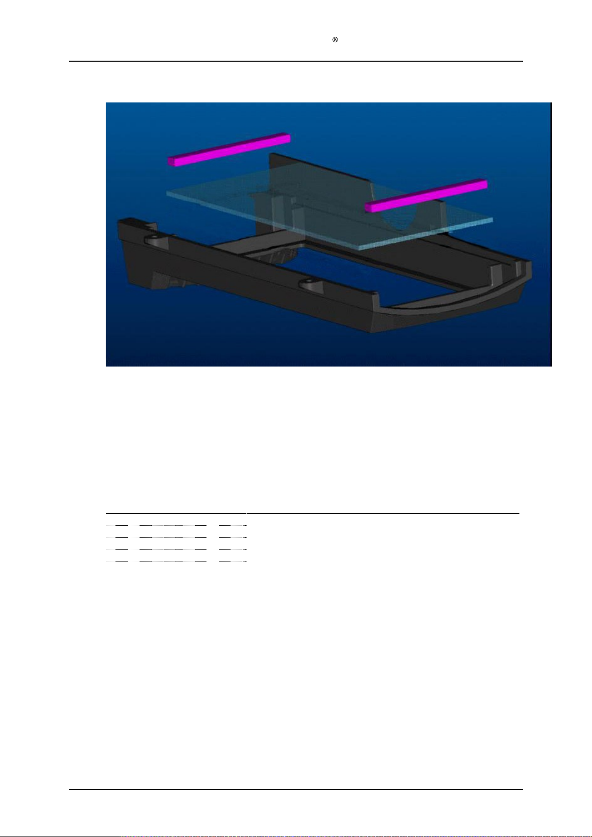
1.7 Housing bottom module (128
-0-
820)
CL128
The housing bottom c
Clean the glass if necessary before final assembly.
1.8 Housing back module (128
Required items
Part #
128
-1-
812
1
128
-1-
905
1
128
-1-
814
4
128
-1-
815
4
Assembly description
Step 1)
Place the fan (128
using the four M4x10 screws (128
must face upwards relative to the housing back (128
the top than at the bottom)
# of items
-1-
905) in the recess of the back housing (128
omes fully assembled as a s
-0-
810) assembly
Description
Housing back (Moulded plastic)
Fan
Screws M4x10 (DIN 7985)
Washer
s
-1-
814) and the four washers (128
-1-
pare part.
-1-
812) and mount the fan
812). (The housing back is wider at
-1-
815). The fan cable
Version 1.
3
Page 9 of 41

Service Manual Aktilite
1.9 Lamp head module (128
-
1.9.1
see slide series
F
ixed lamp head
Required items
Part #
128
-0-
610
128
-0-
400
128
-1-
914
128
-1-
912
128
-1-
916
128
-1-
202
128
-0-
810
128
-1-
928
128
-0-
439
128
-1-
921
128
-0-
750
128
-0-
820
128
-1-
929
128
-1-
890
128
-1-
923
128
-1-
945
inm Chapter 1.9.3
# of items
1
1
2
1
1
1
1
4
1
6
1
1
4
1
2
1
CL128
-0-
200) assembly
.
Description
Housing top module
Positioning arm module
Aluminium washer
Conic spring
Circlip
Power cable
Housing back module
Screws PT 4x30
System electronics module
Screws PT 2,5x8
Light module
Housing bottom module
Screws PT 4x10
Main arm mini cover (moulded plastic)
Screws PT 3x10
Ca
ble tension release
From PS to lamp head (fixed lamp head only)
s
(fixed lamp head only)
Assembly description
Step 1)
Assemble position arm module (128
the short axle of the main arm (128
Step 2)
Slide an alumi
aluminium washer (128
inside of the housing.
Step 3)
Compress the conical spring (128
easiest
done with a special made tool (see pictures)
securely in the groove.
Step 4)
Assemble power cable (128
(128
-0-
400). Leave exc
Step 5)
Position housing back module (128
0-
610). Do not assemble with screws yet.
Step 6)
Insert power cable (128
cable marked 2 is minus [-]), fan cable plug from housing back module (128
from the user interface of the housing top module 128
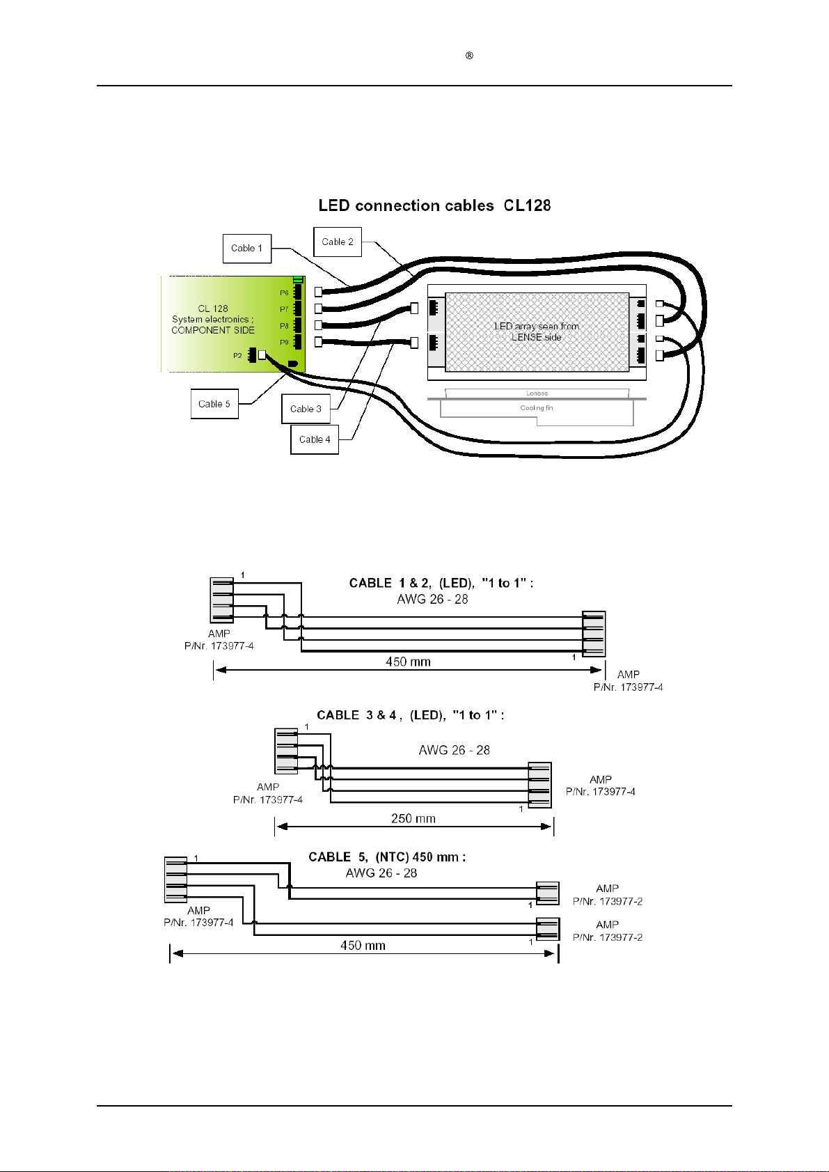
the system electronics module (128
06.03.2002: "LED cables CL128, Rev. A".
Step 7)
Fasten the system electronics module (128
using the six PT 2,5x8 screws (128
302) from the lamp head.
Step 8)
Plug the six cables from the system electronics module (128
connectors on the LED-panels (128
Step 9)
Tidy the cables from the system electronics modul
four miniature cable holders (128
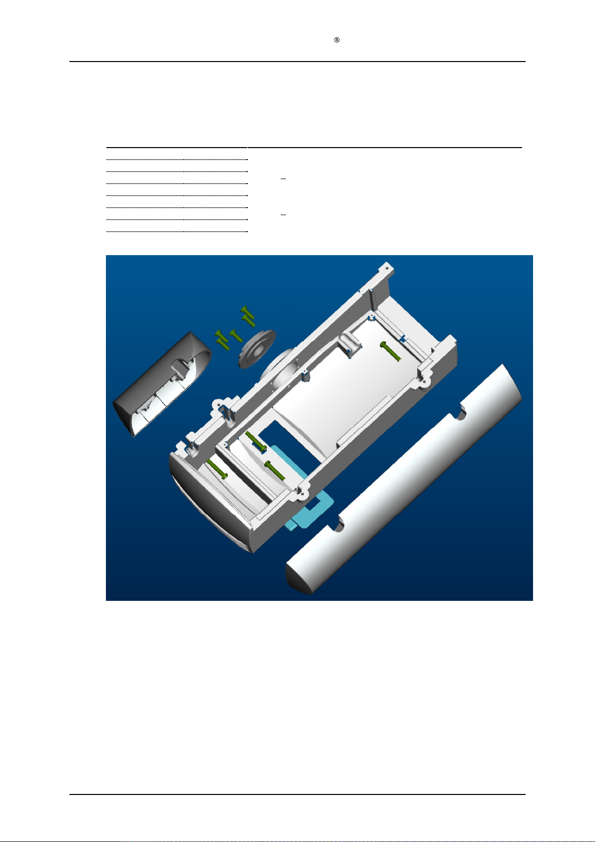
Step 10) Seat the light module (128
Step 11) Remove the protective foil from the protective window
module (128
Step 12) Assemble the housing bottom module (128
using the four PT 4x10 screws (128
Step 13) Fasten the housing back module (128
4x30 screws (128
Step 14) Assemble the main arm mini cover (128
using the two PT 3x10 screws (128
Step 15) Assemble the cable tension release (128
inserting it into the T-piece cover (128
nium washer (128
-1-
914) onto the short axle of the main arm (128
This is very important.
ess cable inside the lamp head to simplify assembly in a later step.
-1-
302) ends into appropriate rece
-0-
-0-
820).
-1-
928).
-0-
400) to housing top module (128
-0-
428) thru the housing top slide bearing (128
-1-
914), a conical spring (128
-1-
912) and assemble the circlip (128
. Make sure that the circlip is located
-1-
302) by inserting the cable thru the positioning arm module
-0-
810) at the back end of the housing top module (128
-0-
-0-
439
). Refer to cable spec from Kitron Development
-0-
439
) to the housing top module (128
-1-
921). And pull out the excess powe
-1-
762) of the light module (128
e (128
-1-
944) on the light module (128
750) properly in the housing top module (128
-0-
820) to the housing top module (128
-1-
929).
-0-
820) to the rest of the lamp head us
-1-
890) to the positioning arm module (128
-1-
923).
-1-
945) around the power cable (128
-1-
424) of the positioning arm module (128
-0-
610) by sliding
-1-
632).
-1-
912) and another
-0-
428) from the
-1-
916). This is
ptors (cable marked 1 is plus [+],
-0-
810) and tail
610 into appropriate connectors on
-0-
610)
r cable (128
-0-
439
) into the appropriate
-0-
750).
-0-
439) by inserting them thru the
-0-
750).
-0-
(128
-1-
826) of the housing bottom
ing the four PT
-1-
610).
-0-
-0-
302) and
-0-
-1-
610)
400)
400).
-
Version 1.
3
Page 10
of 41

Service Manual Aktilite
1.9.2 Detachable lamp head
Required items
Part #
128
-0-
610
1
128
-0-
400
1
128
-1-
914
2
128
-1-
912
1
128
-1-
916
1
128
-0-
810
1
128
-1-
928
4
128
-0-
439
1
128
-1-
921
6
128
-0-
750
1
128
-0-
820
1
128
-1-
929
4
128
-1-
890
1
128
-1-
923
2
# of items
CL128
Description
Housing top module
Positioning arm module
Aluminium washer
Conic spring
Circlip
Housing back module
Screw
System electronics module
Screw
Light module
Housing bottom module
Screw
Main arm mini cover (moulded plastic)
Screw
PT-K 40x30 WN 1452
PT 2,5x8
PT 4x10
PT 3x10
Assembly description
Step 1)
Assemble position arm module (128
the short axle of the main arm (128
Step 2)
Slide an aluminium washer (128
aluminium washer (128
inside of the housing.
Step 3)
Compress the
be done with a special made tool. Similar to a large pair of channel locks, but with custom
heads. Make sure that the circlip is located securely in the groove.
Step 4)
Position housing bac
0-
610). Do not assemble with screws yet.
Step 5)
Insert power cable (128
cable marked 2 is minus [-])
Step 6)
Fan cable plug from housin
the housing top module 128
system electronics module (128
Step 7)
Refer to PCU-010-128 for the connection of the cables going fro
board to the LED arrays..
Step 8)
Fasten the system electronics module (128
using the six PT 2,5x8 screws (128
302) from the lamp head.
Step 9)
Pl
ug the six cables from the system electronics module (128
connectors on the LED-panels (128
Step 10) Tidy the cables from the system electronics module (128
four miniature cable holders (128
Step 11) Seat the light module (128
Step 12) Remove the protective foil from the protective window (128
module (
Step 13) Assemble the housing bottom module (128
using the four PT 4x10 screws (128
Step 14) Fasten the housing back module (128
K 40x30 screws (128
Step 15) Assemble the main arm mini cover (128
using the two PT 3x10 screws (128
128
-1-
914) onto the short axle of the main arm (128
conical spring (128
k module (128
-0-
988) ends into appropriate receptors (cable marked 1 is plus [+],
g back module (128
-0-
-0-
-0-
820).
-1-
928)
.
-0-
400) to housing top module (128
-0-
428) thru the housing top slide bearing (128
-1-
914), a conical spring (128
-1-
912) and assemble the circlip (128
-0-
810) at the back end of the housing top module (128
-0-
810) and tail from the user interface of
610 shall be inserted into appropriate connectors on the
-0-
439
).
-0-
439
) to the housing top module (128
-1-
921). And pull out the excess power cable (128
-1-
762) of the light module (128
-0-
-1-
944) on the light module (128
750) properly in the housing top module (128
-0-
820) to the housing top module (128
-1-
929).
-0-
810) to the rest of the lamp head using the four PT
-1-
890) to the positioning arm module (128
-1-
923).
-0-
610) by sliding
-1-
-1-
912) and another
-0-
428), from the
-1-
916). This must
m the electronic control
-0-
-0-
439
) into the appropriate
-0-
750).
439
) by inserting them thru
-0-
750).
-0-
610).
-1-
826) of the housing bottom
-0-
632).
610)
-1-
610)
-0-
-
the
-
400)
Version 1.
3
Page 11
of 41
Service Manual Aktilite
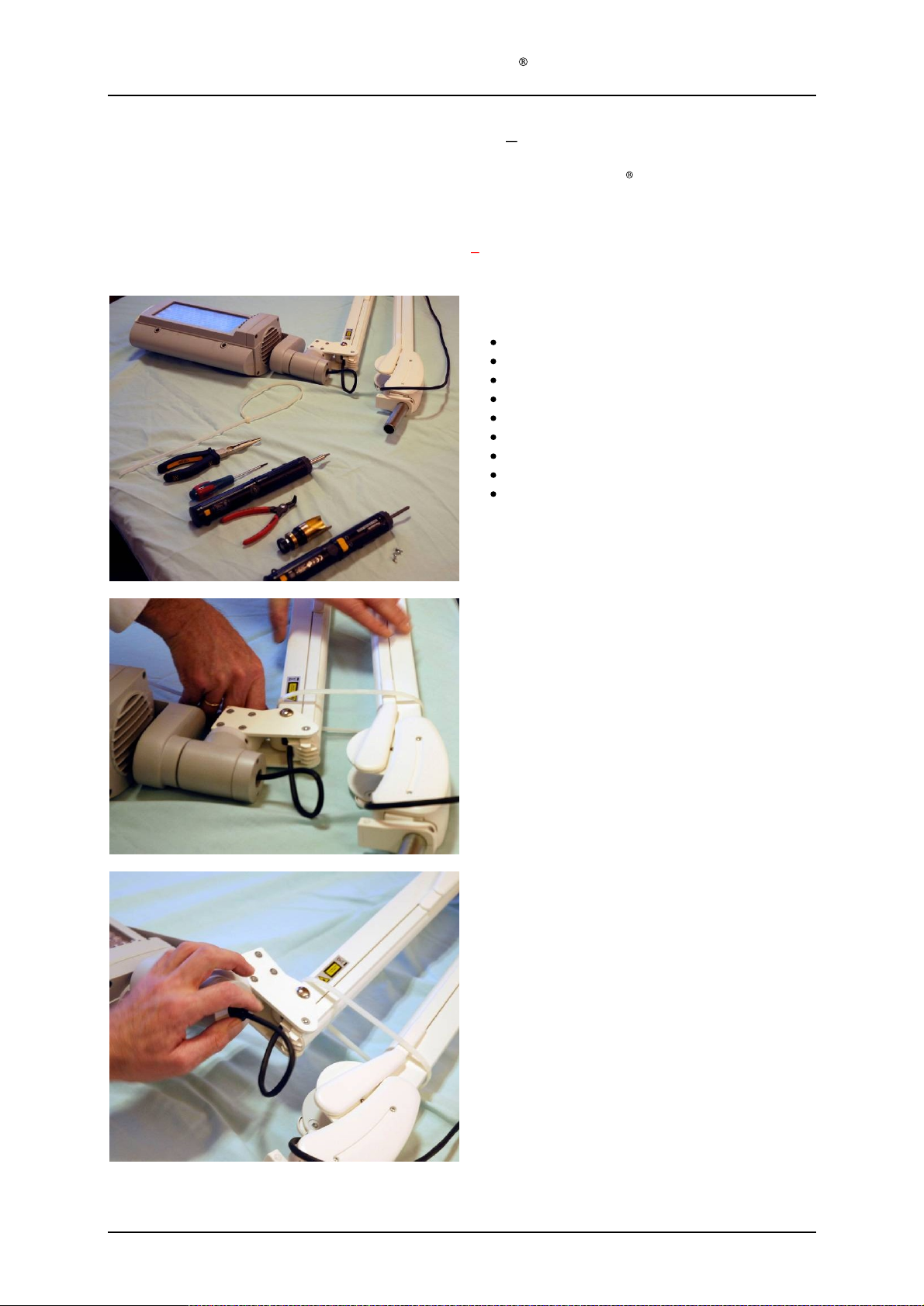
1.9.3 Disassemly and Assembly of
The lamp head module assembly slide series in this chapter is based on
head. However, there are only minor differences between lamp head module assembly for fixed and detachable
lamp head
Warning: The gas springs inside the arm is very powerful
. The below slide series is therefore common for both lamp head variations.
the lamp
therefore secure the arm with a strap
CL128
slide series
Required Tools
Nylon Strap length minimum 45 cm
Pair of telephone pliers
Circlip pliers for 16 mm circlip
Torx T7 screwdriver
Torx T10 screwdriver
Torx T20 screwdriver
Philips PH
Tool to compress the spring mechanism
Allen key (5mm)
the Aktilite
:
2 screwdriver
CL128 with fixed lamp
Step 1
Put on a strap or similar to secure the parallel arm.
Step 2
Step 2-5 is only necessary if you need to take off the
main arm, the housing or replace the cable.
Remove the
main arm using a pair of pliers
F
or lamps with deta
Disconnect the
plug and
lamp head holder locking screw using the
Allen key
strain relief (black) on the end of the
.
chable lamp head:
cable
plug
from the T-piece cover
detach
the lamp head by
.
removing
the
provided
Version 1.
3
Page 12
of 41

Service Manual Aktilite
Step 3
Step 2-5 is only necessary if you need to take off the
main arm, the housing or replace the cable.
Remove the strain relief.
Not applicable for lamps with detachable lamp
head
Step 4
Step 2-5 is only necessary if you need
main arm, the housing or replace the cable.
Remove the small cover on the main arm
T10 screwdriver
CL128
to take off the
using the
Step 5
Step 2-5 is only necessary if you need to take off the
main arm, the housing or replace the cable.
Feed a few cm
loop as shown.
of cord through the arm to make a
Version 1.
3
Page 13
of 41
 Loading...