

Page 1
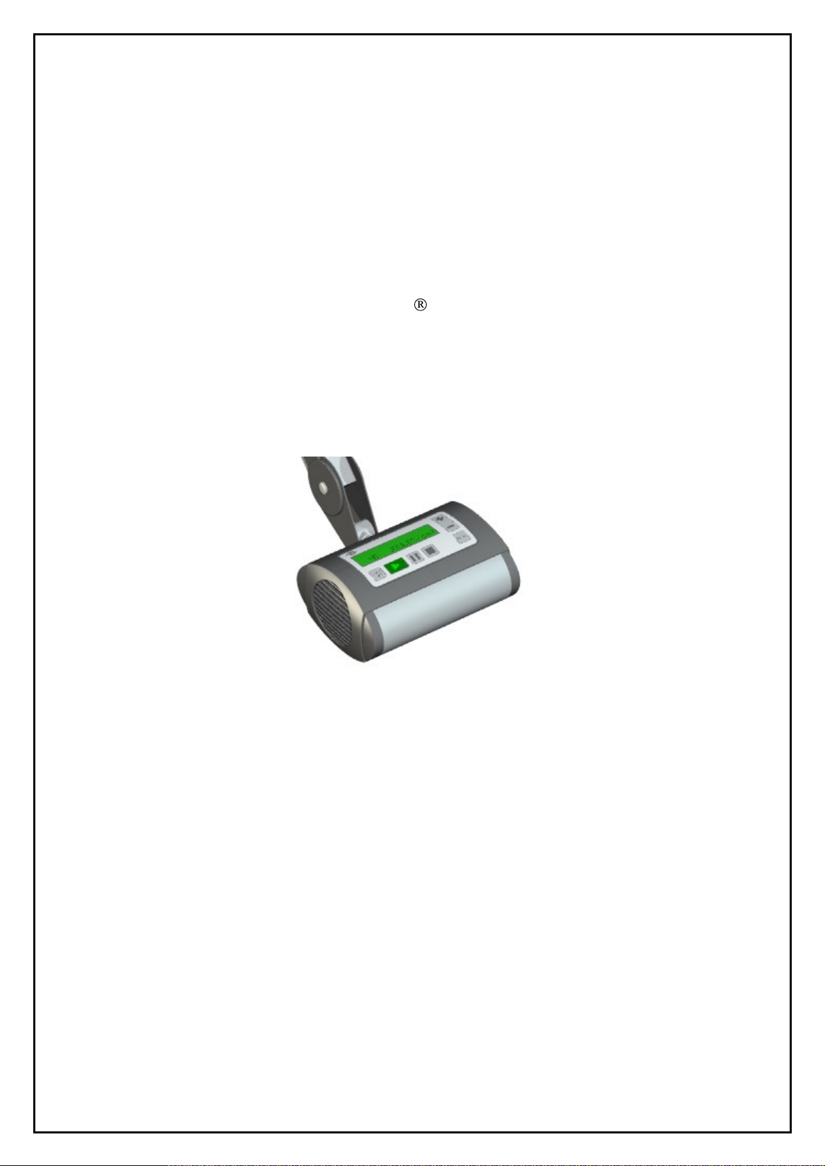
SERVICE MANUAL
Aktilite
Ver 1.
CL16
1
Photoc
Hoffsveien 48
NO-
0377 OSLO, Norway
Phone: +47 22 06 22 10
www.photocure.com
ure ASA
Page 2
Service Manual Aktilite
SERVICE
Aktilite
Any kind of service should only be carried out by authoris
Refer to the User Manual for further information regarding safety and precautions.
TABLE OF CONTENTS
1
Assembly of Aktilite
CL16 Lamp with Parallel Arm
MANUAL
CL16
CL16
ed personnel.
.................................................
3
1.1 Material/Equipment
1.2 Housing bottom module (16
1.3 Housing fansid
1.4 Light module (16
1.5 Housing top module (16
1.6 Lamp head module (16
1.7 Lamp head and parallel arm module (16
1.8 Labels placement description
2
Replacing the DC Power Plug
3
Assembly of Aktilite
3.1 Material/Equipment
3.2 Cable pack input (16
3.3 Cable pack output (16
3.4 Power supply (16
4
Error Codes
....................................................................................................................17
.....................................................................................................
-0-
200) assembly
e module (16
-0-
400) assembly
CL16 CON
...................................................................................................14
-0-
-0-
650) assembly
-0-
300) assembly
-0-
500) assembly
-0-
800) assembly
....................................................................................12
.......................................................................................13
DOR Power Supply
670) assembly
-0-
680) assembly
.............................................................
............................................................
..............................................................................
...................................................................
....................................................................
-0-
900) assembly
......................................................................14
....................................................................15
...........................................................................15
.......................................11
...............................................14
3
4
5
6
7
8
Version 1.1
Page 2 of 18
Page 3
1
1.1 Material/Equipment
Assembly of Aktilite
Tools needed for the assembly of the Aktilite
Required tools
# of items
1
1
1
1
1
-
-
-
Description
Screwdriver, Torx 10 Tool A
Screwdriver, Tor
Tool C: special tool for pressing the axle, arm into the heat sink
Tool D: small, flat screwdriver
Plug assembler tool (ELFA 80-490-58)
Silicone
Glue B
Rubbing alcohol (fat free)
Service Manual Aktilite
CL16 Lamp with Parallel Arm
x 20 Tool B
CL16
CL16 lamp
Tool E
Version 1.1
Page 3 of 18
Page 4
Service Manual Aktilite
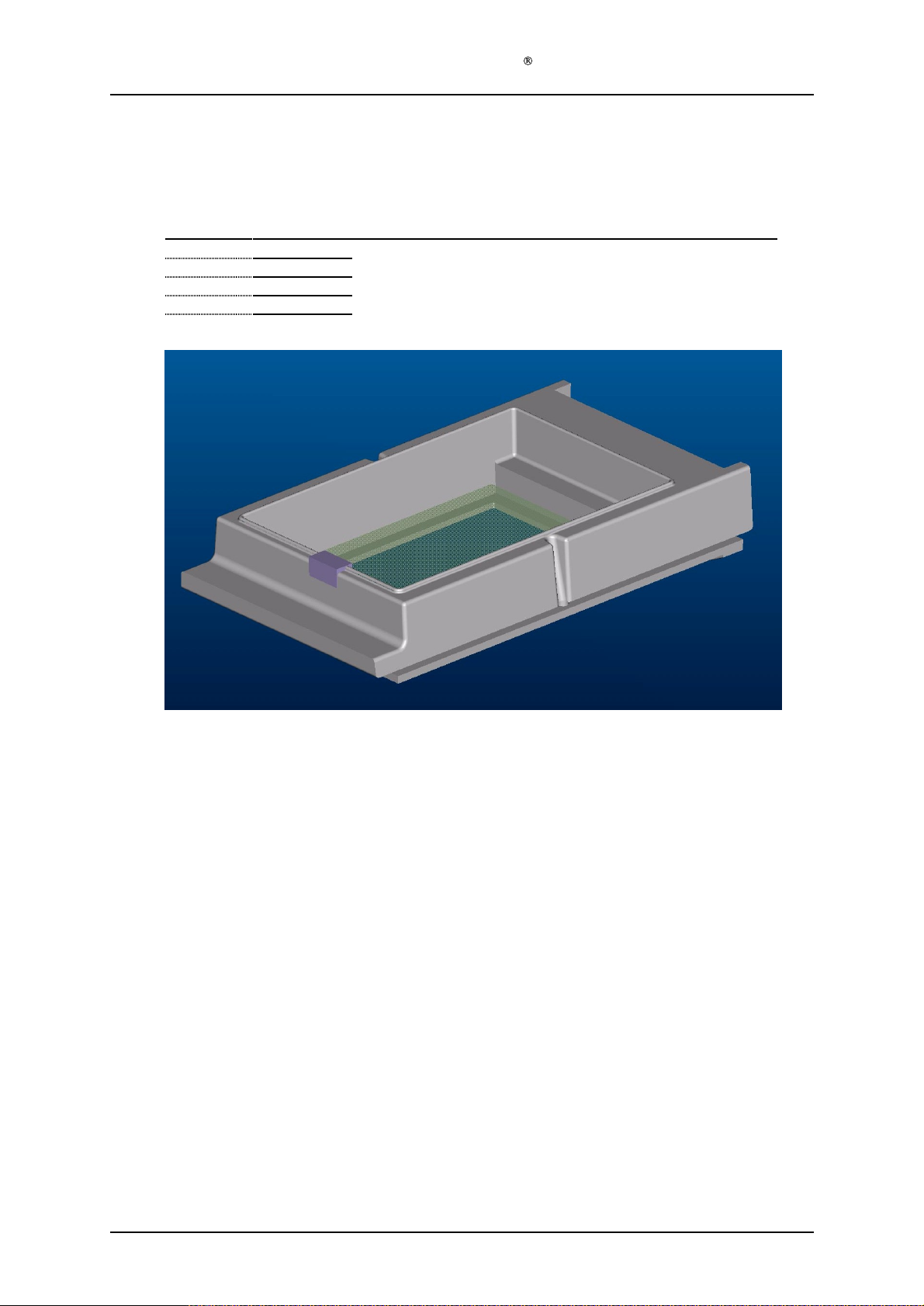
1.2 Housing bottom module (16
Required items
Part #
16
-1-
201
1
16
-1-
202
1
16
-1-
203
1
16
-1-
206
# of items
Description
Housing bottom
Gasket, cable, bottom
Protective window
Silicone
Rubbing alcohol (fat free)
-0-2
00) assembly
CL16
Assembly description
Step 1) Clean the recessed area at pro
Step 2) Attach the protective window (16
Step 3) Remove the protective paper from the Gasket, cable, bottom (16
against the hou
As a spare part this comes fully assembled.
sing bottom (16
tective window (16
-1-
203) to the housing bottom (16
-1-
201).
-1-
203) using a cloth and rubbing alcohol.
-1-
201) using silicone.
-1-
202), and press it firmly
Version 1.1
Page 4 of 18
Page 5
Service Manual Aktilite
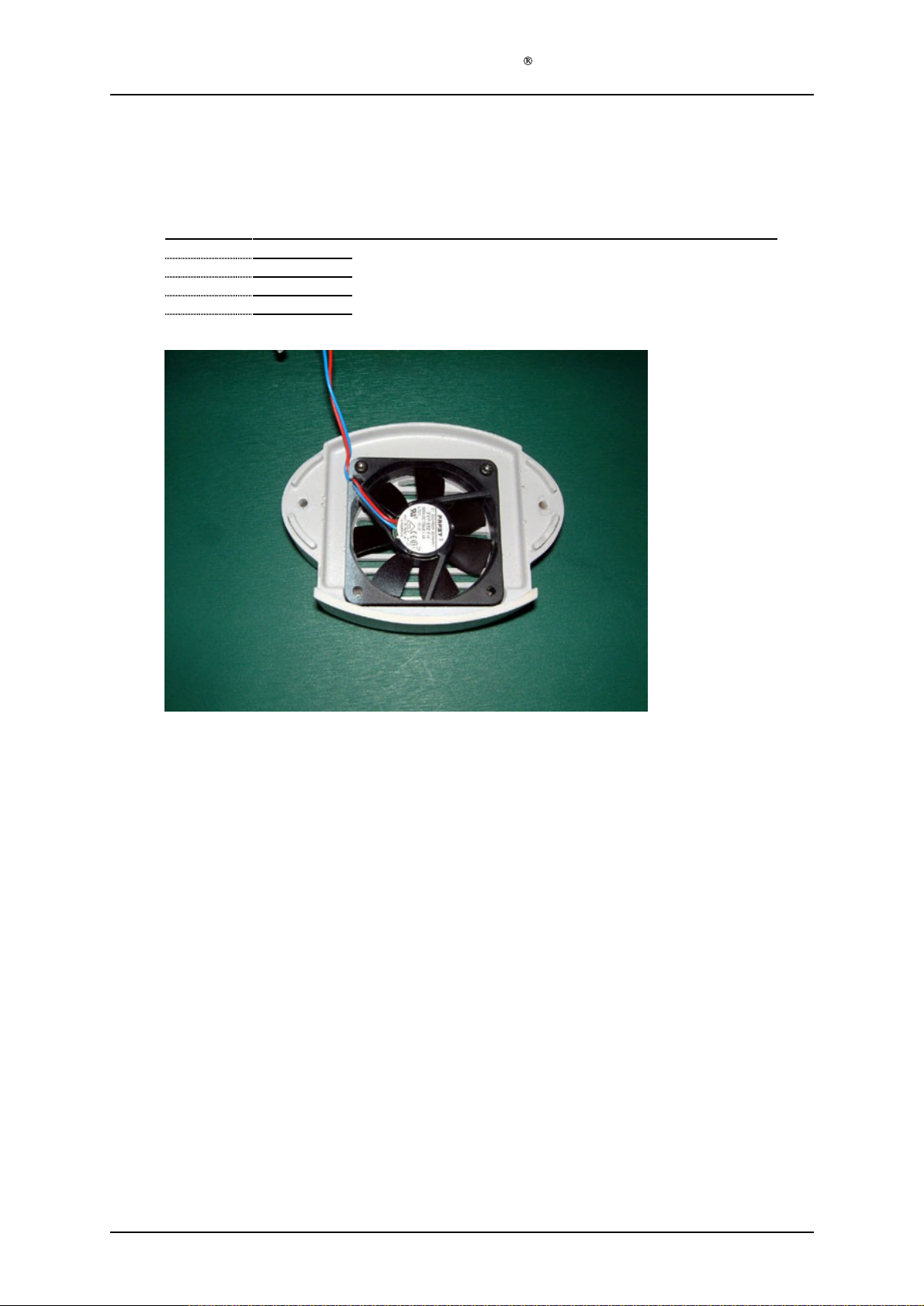
1.3 Housing fanside module (16
Required items
Part #
16
-1-
301
1
16
-1-
302
1
16
-1-
303
2
# of items
Description
Housing, fan side
Fan Papst 612 FH, with cable and connector
Screws, Fan - Housing, fan side
Tool A: Screwdriver, Torx 10
Glue B
-0-
300) assembly
CL16
Assembly description
Step 1) Place the fan (16
Step 2) Screw the two screws (16
together.
Step 3) Put a drop of glue in the channel where the cords go into the centre section of the fan.
-1-
302) in the housing
-1-
303) in the upper holes to keep
fan side
(16
-1-
301) with the cable oriented correctly
the fan and the housing
fan side
Version 1.1
Page 5 of 18
Page 6
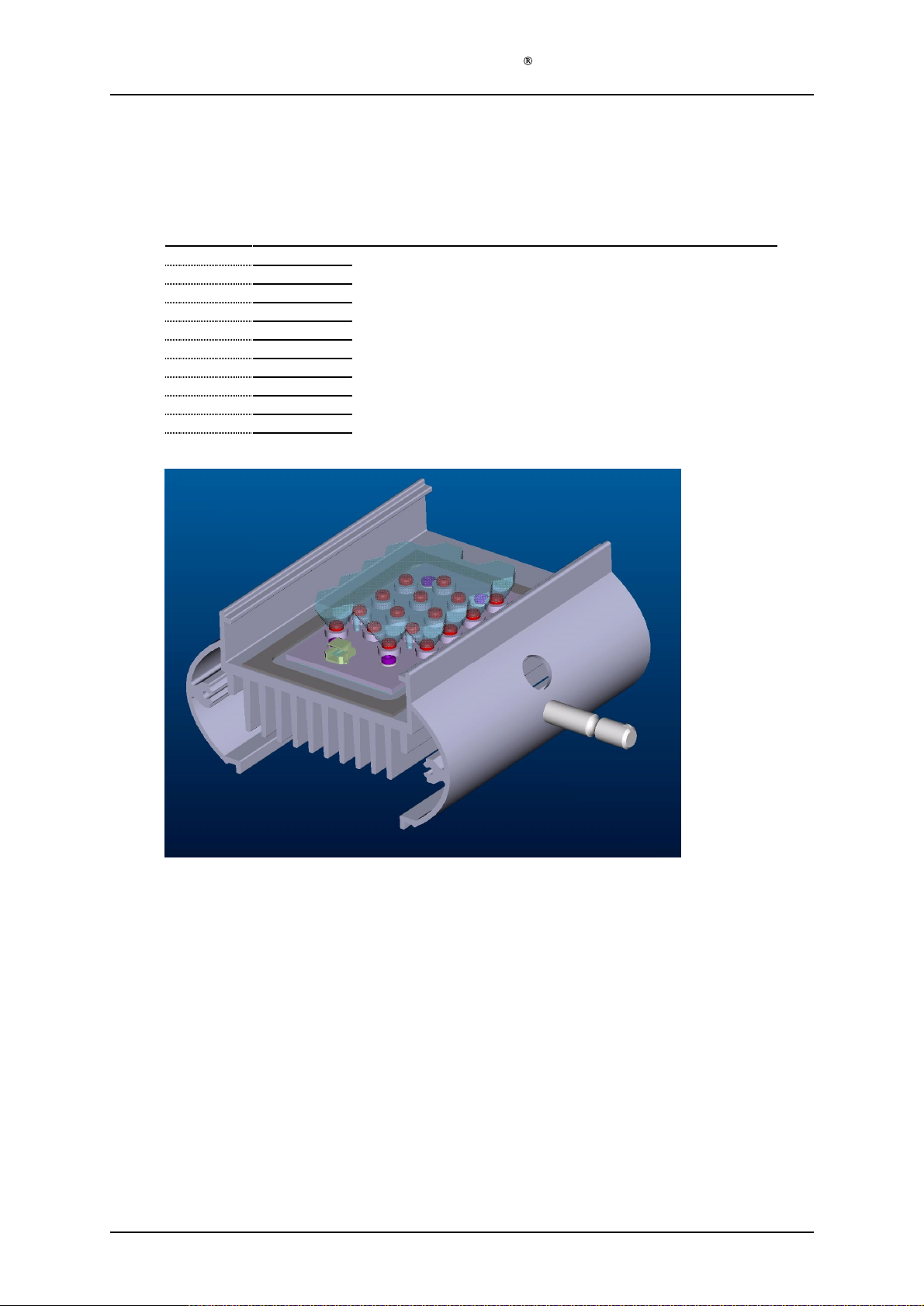
1.4 Light module (16
Required items
Part #
16
-1-
401
1
16
-1-
402
1
16-1-
420
1
16
-1-
404
1
16
-1-
405
1
16
-1-
406
1
16
-1-
407
4
16
-1-
408
4
16
-1-
410
# of items
Service Manual Aktilite
-0-
400) assembly
Description
Lens
LED-panel
Heat sink, machined with logo
Heat conductive pad, LED
Gasket, frame, bottom
Axle, arm
Washers, for screws in LED-panel
Screws, LED-panel - heat sink
Tool B: Screwdriver, Torx 15
T
ool C (special tool for pressing the axle, arm into the heat sink)
Glue B
CL16
Assembly description
Step 1) Press the axle, arm (16
Step 2) Turn the heat sink upside-down and place the "heat conductive pad, LED" (16
Step 3) Perform a visual inspection of the soldering joints on the
Step 4) Place the LED panel (16
Step 5) Screw the screws (16
Step 6) Remove the protective paper from the self-adhesive Gasket, frame, bottom (16
Step 7) Apply a small drop of Glue B (16
Step 8) Put a light pressure onto the lens module until the glue has cured.
Step 9) This module is now going to be optically tested before further assembly.
Version 1.1
-1-
406) into the hole on the heat sink (16
on the axle is facing straight downwards. Special
that its holes lines up with the holes in the heat sink.
-1-
402) on the "heat conductive pad, LED" (16
the contact on the LED panel is facing in the correct direction.
-1-
408) with washers (16
the heat sink.
place it on the heat sink, as close as possible to the LED-panel on its contact side.
lens in position, assuring that its four "towers" enters the holes.
-1-
410) in the four holes on
pressing tool or jig should be used for this.
-1-
407) through the holes on the LED-panel to
-1-
420), assuring that the tap
-1-
LED array PCBs.
the LED panel and place the
-1-
404), assuring that
-1-
404) on it so
405), and
Page 6 of 18
Page 7
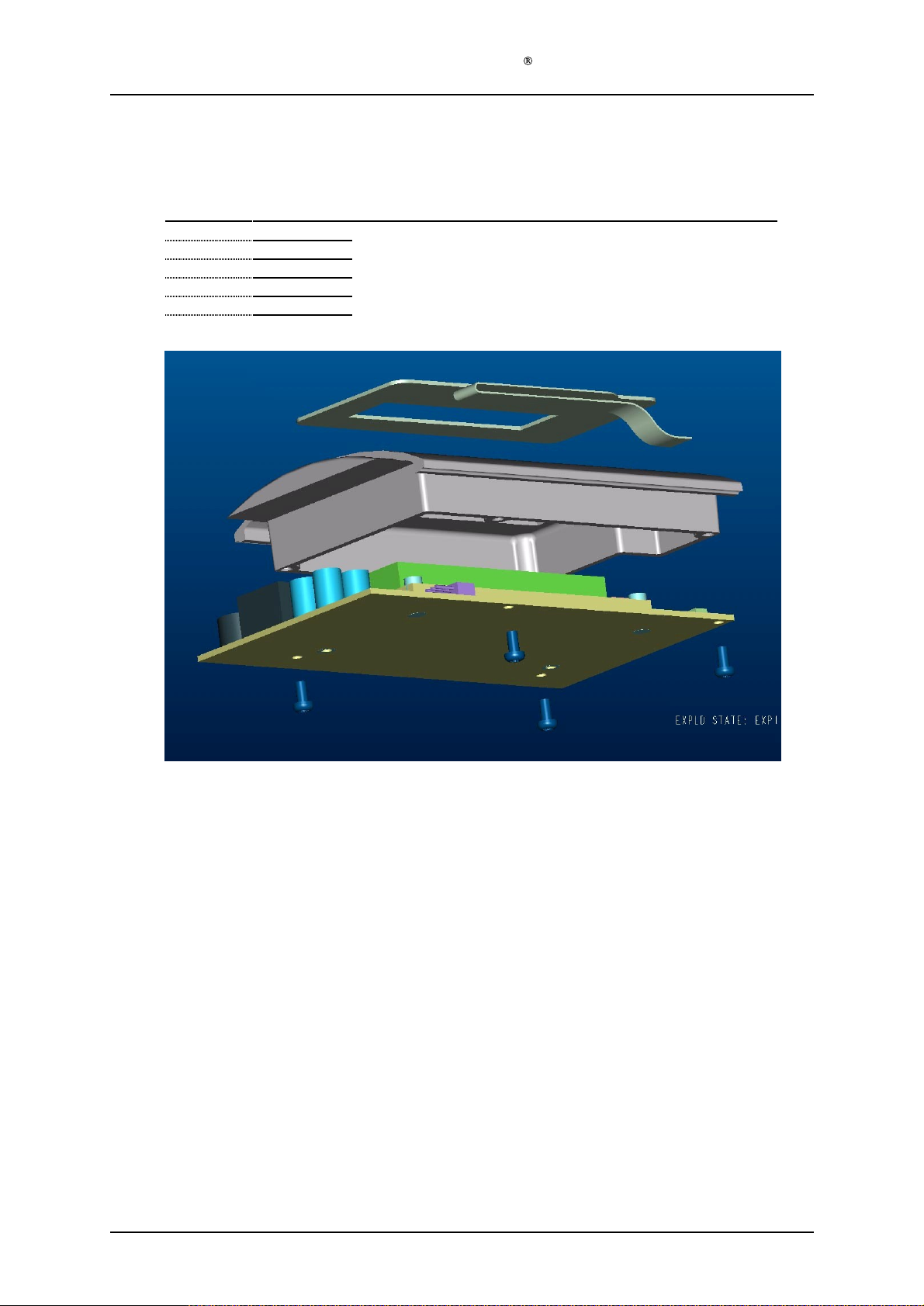
1.5 Housing top modul
Required items
Part #
16
-1-
501
1
16
-1-
502
1
16
-1-
503
4
16
-1-
602
1
# of items
Service Manual Aktilite
e (16
-0-
500) assembly
Description
User interface
Housing top
Screws Electronics- Housing, top
System electronics
Tool A: Screwdriver, Torx 10
Rubbing alcohol
CL16
Assem
Step 1) Clean the recessed area at the top of the housing top (16
Step 2) Remove the protective paper from the self-adhesive key touch panel (16
Step 3) Put the flex-tail in the connector on the system electronics (16
Step 4) Assure that the flex-tail falls smoothly into place and assemble the system electronic
Version 1.1
bly description
alcohol
the housing top (16
by pressing the black part down and in.
600) to the housing top (16
-1-
502), leading the flex-tai
-1-
502) using the 4 screws (16
-1-
502) using a cloth and rubbing
-1-
501) and glue it to
l through the corresponding hole.
-0-
600) and close the connector
-1-
503).
s (16
-0-
Page 7 of 18
Page 8
Service Manual Aktilite
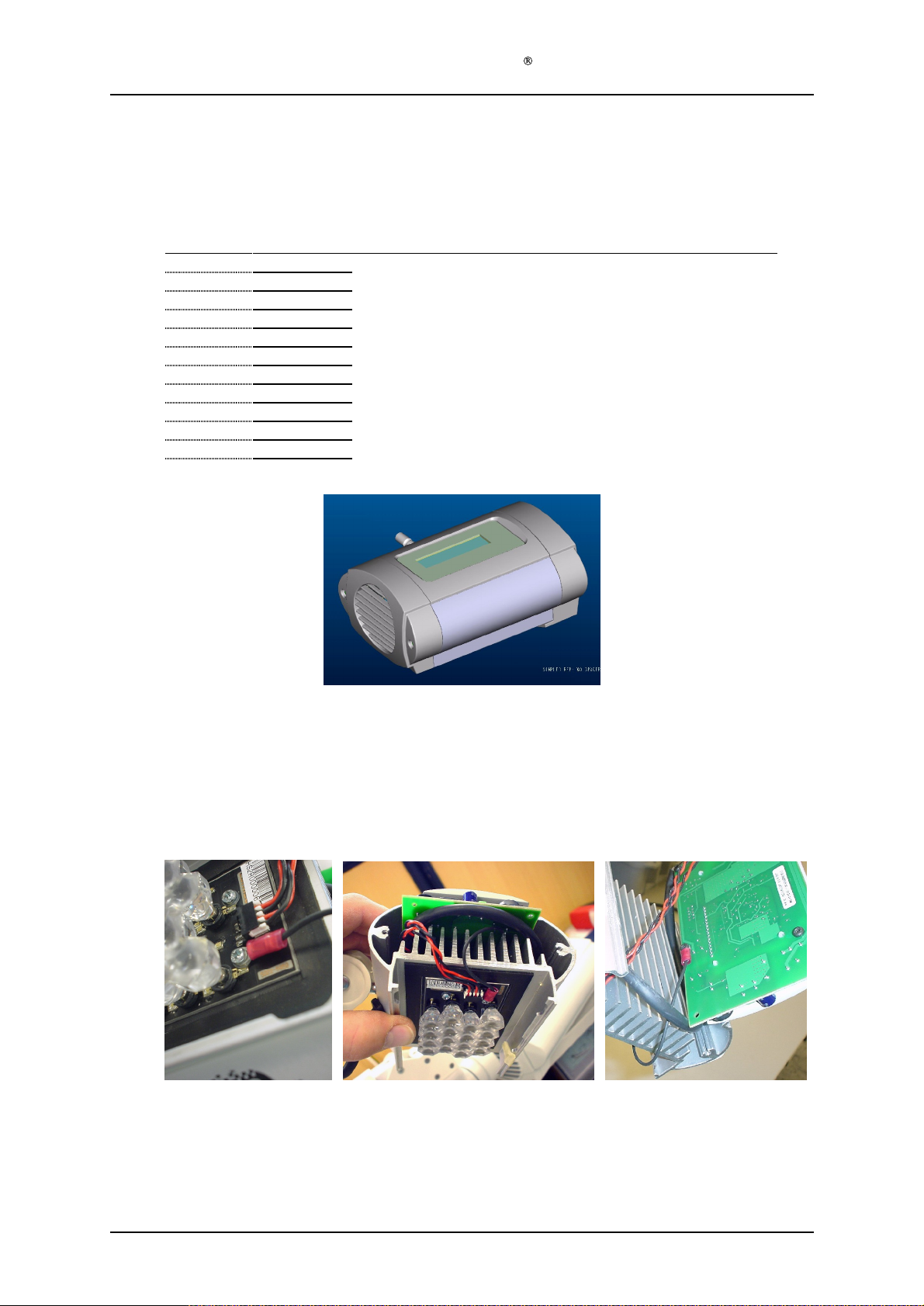
1.6 Lamp head module (16
Required items
Part #
16
-1-
801
1
16
-0-
200
1
16
-0-
300
1
16
-0-
400
1
16
-0-
500
1
16
-0-
700
1
16
-1-
802
4
16
-1-
809
1
16
-1-
810
1
16
-1-
811
1
# of items
Description
Housing outlet side
Housing bottom module
Housing fanside m
Light module
Housing top module
Arm & accessories module
Screw, Housing, sides - heat sink
Cable A from power supply to lamp head
Cable B from LED-panel to electronics
Cable tension release
Tool A: Screwdriver, Torx
Tool D: small flat screwdriver
-0-
800) assembly
odule
CL16
10
Assembly description
Step 1) Connect the cable B (16
to the connector on the LED-panel in the housing bottom module (16
Step 2) Connect the Earth cable between the 'M2' plated hole of the PCB and the chassis of the lamp
(cooling fin/metal body of the lamp). Refer to cable spec. from Kitron Development "LED
cables CL16" Rev.A
Step 3) With the front of
0-
500) into it from left to right
Step 4) Put the Cable A 16
connector A in the housing top module (16
connector open.
-1-
810) to the connector B in the housing top module (16
-0-
200)
the Light module (16
-1-
809 through the hole in the housing top module and put it in the
-0-
400) against you, slide the Housing top module (16
-0-
500), using a smal
l screwdriver to press the
-0-
500) and
-
Version 1.1
Page 8 of 18
Page 9
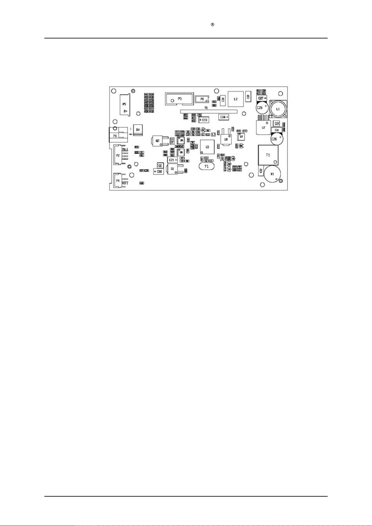
Service Manual Aktilite
Step 5) Seen from the terminal input side, cord marked 1 [+] goes to the right side of the terminal, and
cord marked 2 [-] goes to the left side of the terminal.
Step 6) Still with the front of the Light module (16
side to its left side, using two screws (16
Step 7) Put the Housing bottom module (16
hit by the gasket on the Housing bottom module
Step 8) Connect the cable from
in the housing top module (16
Step 9) Assemble the Housing fan side, using the two screws (16
Step 10) Press in the cable tension release (16
pliers for this.
the fan in the Housing fan side module (16
-0-
500)
-0-
-1-
-0-
200) in its place, assuring that the Cable A (16
-1-
811) where the cable enters the heat sink. Us
400) a
802)
CL16
gainst you, assemble the Housing outlet
-0-
300) to the connector C
-1-
802).
-1-810) is
e a pair of
Version 1.1
Page 9 of 18
Page 10
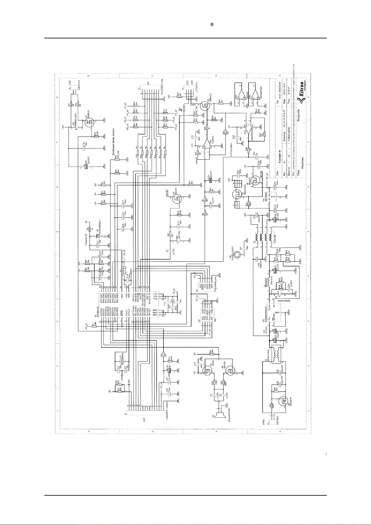
Service Manual Aktilite
CL16
Version 1.1
Page 10
of 18
Page 11
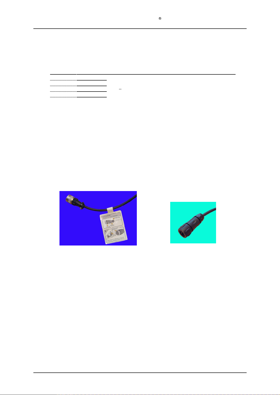
Service Manual Aktilite
1.7 Lamp head and parallel arm module (16
Required items
Part #
16
-0-
800
1
16
-1-
901
1
16
-1-
902
1
16
-1-
813
Assembly description
Step 1) Unscrew the friction unit of the Parallel arm, insert the axle arm from the Lamp head module,
and tighten until the friction is sufficient
Step 2) Tread the cable from the Lamp head module (16
Step 3) Put on the strain relief.
Step 4) Assemble the plug onto the cable (16
and cord marked 2 to "B" [-] in the
solder the pins
the two self-threading screws to secure the pressure pad on the strain relief, with the lowered
side facing the cab
position, there is a special tool available to remove the pins again.
Step 5) Remove the protective paper from the backside of the label Power Plug. (16
attach the label to the co
# of items
Description
Lamp head module
Parallel arm (with friction unit towards axle arm)
Plug
Label Power Plug
Tool E: Plug assembler
. Use one drop of Loctite and screw on the strain relief to
le. NOTE:
rd, next to the
On cable fro
If you by accident put the pin in the
m lamp head to PS
.
-1-
902), attaching cord marked 1 to "D" [+] in the plug
bayonet
bayonet
CL16
tool (ELFA 80-490-58)
-0-
pl
ug. Use the crimping tool for the crimp pins
plug, as shown in the picture below.
-0-
900) assembly
800) through the Parallel arm (16
bayonet
bayonet
plug. Use
plug in the wrong
-1-
813) and
-1-
901).
or
NB! Use new stronger plug Souriau UTS 6JC104P
for repaired lamp
s.
Version 1.1
Page 11
of 18
Page 12
Service Manual Aktilite
1.8 Labels placement description
Required items
Part #
16
-0-
900
1
16
-1-
904
1
16
-1-
903
1
# of items
Description
Lamp including paralle
Label Serial Number
Label Warning and Special Waste
CL16
l arm
Assembly description
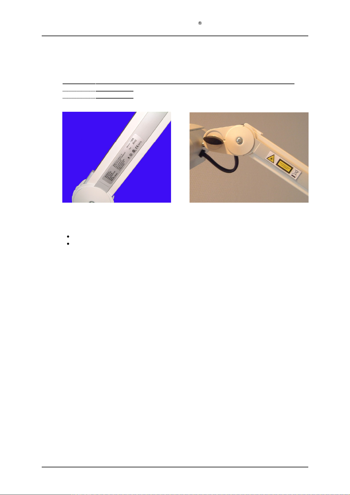
Place the labels according to the pictures above. Note that the two labels should be placed on opposite
sides of the lamp arm:
Label Serial no. on the right side, near the bottom end of the arm
Label Warning and Special Waste
on the left side, near the lamp head
Version 1.1
Page 12
of 18
Page 13
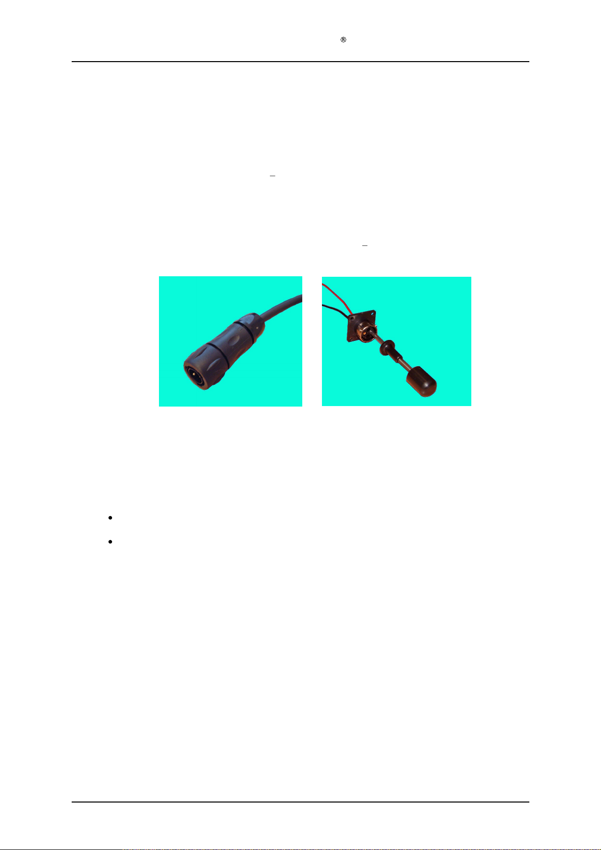
2
Service Manual Aktilite
Replacing the DC Power Plug
Assembly description
Step 1)
Put the stain relief onto the DC power cable. Put on the male crimp pins using the specially
made crimping tool. Put the cord numbered 1 into "D" [+] in the bayonet p
with cord marked 2 in "B" [
specially made extractor tool to release the pins from the bayonet plug again.
Step 2)
Put a drop of Loctite on the threads at the strain relief threads and
the bayonet plug.
Step 3)
Double check:
] in the bayonet plug. If you make a mistake, you can use the
Cord marked 1 into "D" [+ or red]
Cord marked 2 into "B" [
CL16
or black
lug, and the pin
screw the strain relief to
]
New plug
To use the extractor tool, press the tool f
centrepiece of the tool, and continue to press onto the top piece.
If wires have to be reconnected to the pins, it is recommended to solder them on,
as otherwise this requires special crimping tools.
Part number for
(
RM16M23K
Part number for the wall mounted connector is 128
pins 128
-1-
)
345
(RC16M23K)
the plug is: 128
-1-
261 Souriau UTS 6JC104P with pins (extra) 128
Extractor tool
irmly into the connector by holding the
-1-
323 261 Souriau UTO 0104SH
-1-
263
with mating
Version 1.1
Page 13
of 18
Page 14
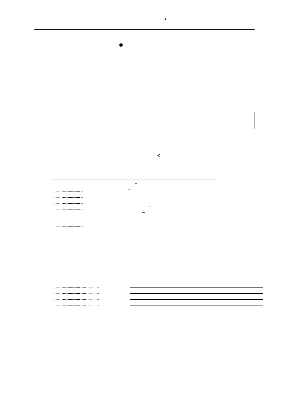
3
3.1 Material/Equipment
Assembly of Aktilite
Note: This is only used for the Nordic Markets. The other markets uses a Mascot
power supply.
Aktilite CL16 is delivered with two different power supplies, depending on the
market: CONDOR power supply and MASCOT power supply. The CONDOR power
supply is only de
NOTE: This assembly procedure is only valid for CONDOR power supply. The
MASCOT power supply is not to be opened and must be replaced if not working.
Tools needed for the assembly of the Aktilit
livered on the Scandinavian markets.
Service Manual Aktilite
CL16 CONDOR Power Supply
e CL16 CONDOR Power Supply
CL16
Required tools
# of items
1
1
1
1
1
1
1
-
3.2 Cable pack input (16
Required items
Part #
16
16
16
16
16
-1-
671
1
-1-
672
1
-1-
673
1
-1-
674
3
-1-
675
1
Description
Screwdriver, Pozidrive 2
Screwdriver, Torx 10 Tool B
Screwdriver, Torx 20 Tool C
Cable shoe mounting tong
AMP-Connector mounting tong
Crimp
Voltage adjusting jig
Lacquer (for sealing pot meter)
socket mounting tong
# of items
Tool A
Tool E
Tool G
-0-
670) assembly
Description
Cable A, blue neutral AC conductor
Cable B, brown l
Cable C, green/yellow ground cable
Cable shoes, flat type
Connector AMP
Tool E: Cable shoe mounting tong
Tool F: AMP-Connector mounting tong
Tool F
ive AC conductor
Assembly description
Step 1) Assemble one cable shoe (16
Step 2) Assemble the three cables to the connector using tool F. Assure that they are placed like this:
Version 1.1
-1-6
74) to each of the three cables, using tool E.
pin 1 = Cable A (AC neutral), pin 2 = Cable C (NO Pin), Pin 3= Cable B (AC Live)
Page 14
of 18
Page 15
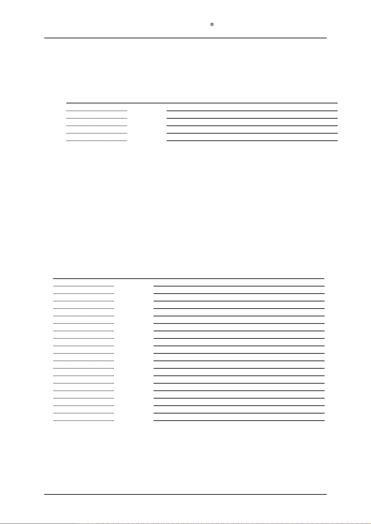
Service Manual Aktilite
3.3 Cable pack output (16
Required items
Part #
16
-1-
681
1
16
-1-
682
1
16
-1-
683
2
16
-1-
684
1
Assembly description
Step 1) Assemble one crimp socket (16
Step 2) Assemble the two cables to the connector using tool F. Assure that they are placed like this:
P
in 5= Cable E (
P
in 2= Cable D (+) Red
# of items
-) Black
CL16
-0-6
80) assembly
Description
Cable D, red load cable
Cable E, black load cable
Crimp socket
Connector AMP
Tool F: AMP-Connector mounting tong
Tool G: Crimp socket mountin
-1-
683) to each of the two cables, using tool G.
s
g tong
Pi
n 1 is marked on the Printed Circuit Board
3.4 Power supply (16
Required items
Part #
16
-1-
651
1
16
-1-
652
1
16
-1-
653
4
16
-1-
654
1 W
16
-1-
655
4
16
-1-
656
1
16
-1-
657
2
16
-1-
658
4
16
-1-
659
1
16
-1-
660
1
16
-1-
661
4
16
-1-
662
4
16
-1-
664
1
16
-0-
670
1
16
-0-
680
1
# of items
-0-
650) assembly
Description
Casing, machined
Power - Condor GLM65
Washer
all mounted connector Souriau UTO 0104SH
Screws PS-casing
In plug (IEC 320)
Screws In-plug
Dist washer
Ferrite (Load side)
Ferrite (Mains side)
Feet pads (self adhesive)
Screws Out-plug
Label with Approvals
Cable pack input
Cable pack output
Tool A: Screwdriver, Pozidrive 2
Tool B: Screwdriver Torx 10
Tool C: Screwdriver Torx 20
Voltage adjusting jig
Laquer (for sealing pot meter)
-48
s
Version 1.1
Page 15
of 18
Page 16
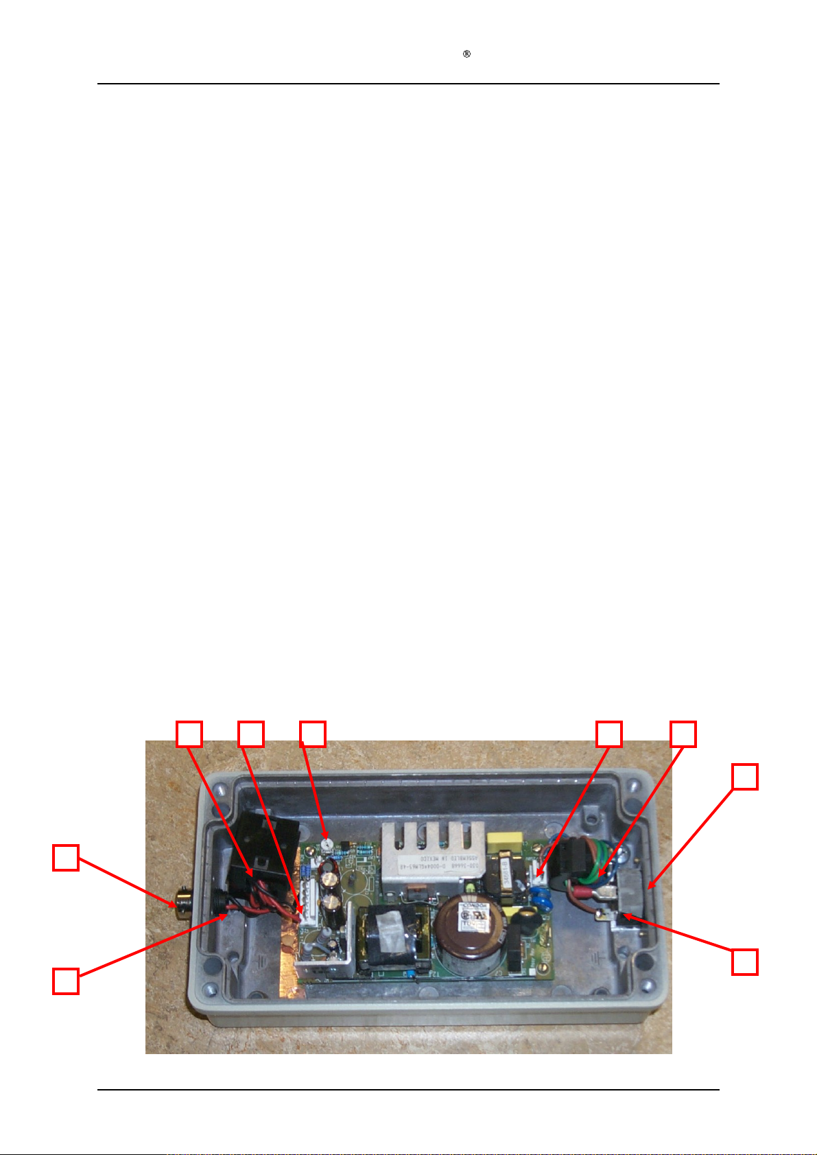
Service Manual Aktilite
Assembly
Step 1) Connect the
Step 2) Assemble the
Step 3) Thread both cables in the Cable pack input (16
Step 4) Thread all three cables in the
Step 5) Assemble the
Step 6) Assemble the
Step 7) Connect the crimp sockets of the
Step 8) Assemble the
Step 9) Connect the three cables in the
Step 10) Fix the ferrites to the casing with a strip, silicon or other means.
Step 11)
Step 12) Connect the 5 cables to the
Step 13) Apply
Step 14) Remove the protective paper and assemble the four self-adhesive
Step 15) Note the serial number on the underside of the box. Take out the QA documen
Step 16) The unit is now ready for further testing.
description
connector.
connector.
(16
-1-
cable) (16
658)
that the red and black load cables are on the same side as the power outlet plug. Use the Tool
C.
Screws Out plug (16
3 locking pins facing upwards. Use Tool B.
red and black load cables into the correct holes in the power outlet plug. The red cable (+)
goes into the slot marked D, and the black cable (-) goes into the slot marked B.
(16
-1-
upwards. Use Tool B.
Cable A (blue) is connected to pin m
marked L, and Cable C (green/yellow) is connected to pin marked with the ground symbol.
Close the
Volt by adjusting the blue pot meter near the DC power output terminals. Secure the pot
meter by a drop of lacquer. (ref. TCU-002
underside of the casing, one in each corner.
follows the "Traveller" for the DHR.
660)
4 times.
-1-
between. Use the 4
657)
. Make sure it is fastened in the correct position, with the central pin facing
casing (16
Label Nemko
Cable pack input (16
Cable pack output (16
659)
3 times.
Power (16
DC power outlet plug (16
AC in plug (16
-1Screws PS-Casing (16
-1-
662)
-1-
651)
(16
-1-
-0-
Cable pack output (16
652)
into the
. Make sure it is fastened in the correct position, with one of the
Cable pack output (16
-1-
656)
Cable pack input (16
and screw it tog
voltage adjusting jig
663)
to the underside of the casing.
670)
-0-
680) the
casing (16
-1-
onto the
arked N, Cable B (brown) is connected to the tongue
CL16
to the
power (16
power (16
-0-
-1-
654)
onto the
casing (16
ether.
terminals, and set the output voltage to 50.4
-16C)
670)
through the
-0-
680)
-1-
651)
655)
with
-0-
-0-
670)
-1-
652)
in its responding AMP
-1-
652) in its responding AMP
ferrite (mains cables)
through the other
with the
casing (16
680)
-1-
651)
to the
distance
washers (16
to the DC out plug. Pl
with the 2 Screws in plug
-1-
653)
-1-
651)
, with the four
AC in plug (16
feet pads (16
ferrite (load
washers (16
. Make sure
ug the
-1-
656)
-1-
661)
to the
tation that
-1-
.
Version 1.1
Page 16
of 18
Page 17
Service Manual Aktilite
4
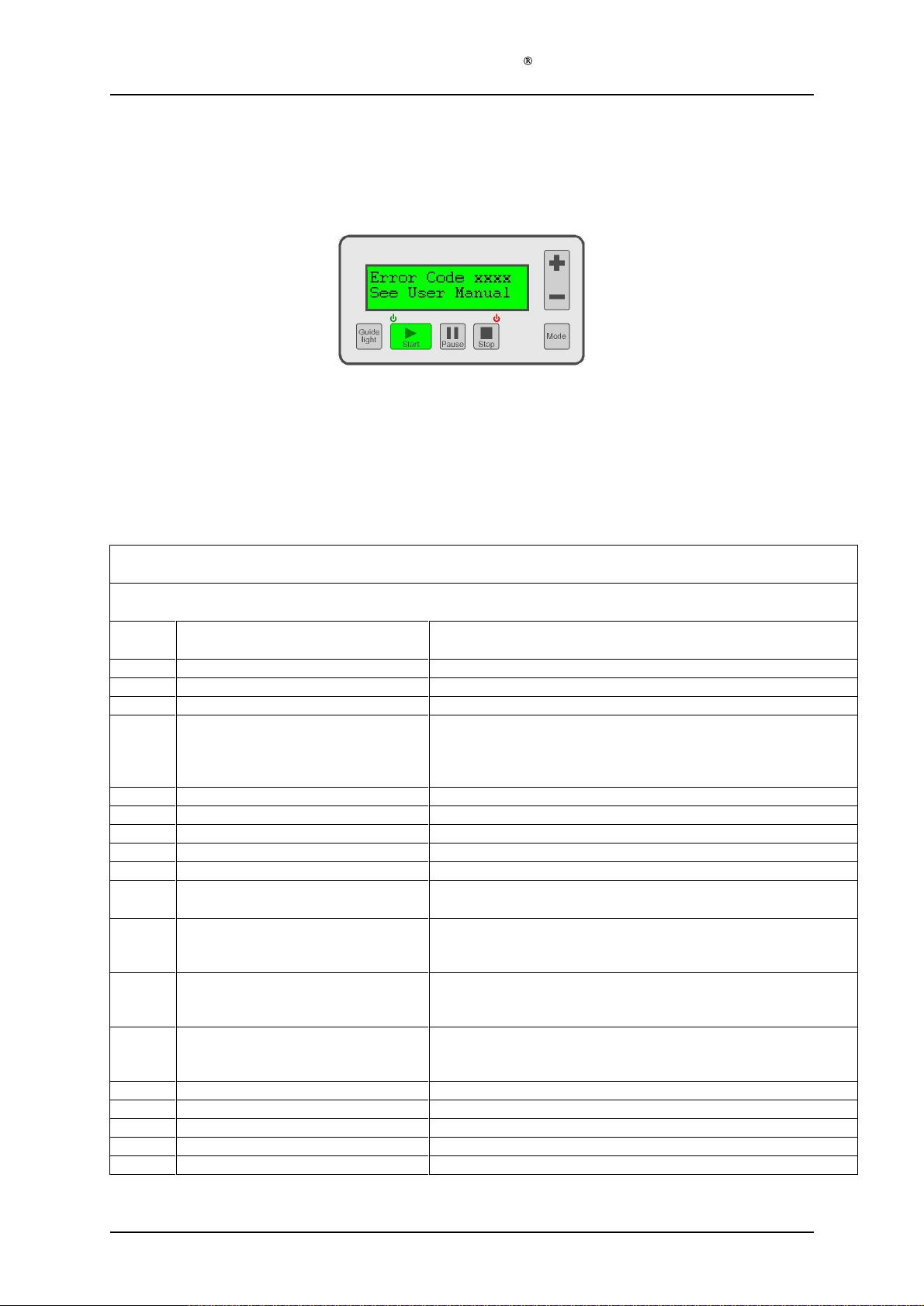
The Aktilite CL16 has in-built monitoring features. If an error should occur, the display will show the following
message and
If an error code is displayed, or if any other unexpected c
following steps should be taken:
1. Disconnect the mains cable for at least 20 seconds
2. Reconnect the mains cable
3. Check all cables and connections
4. Switch on and check if the lamp can be used as normal
5. If the e
Error Codes
five rapid beeps will be heard:
rror persists, refer to the table below
CL16
ondition occurs (e.g. lamp does not operate), the
Error
Code
1101
1102
1103
1104
1105
1107
1109
1110
1112
1117
1206
1208
1211
2105
2107
2109
2110
2112
NOTE: Refer to the instructions above before using the table
Device internal error
Device internal e
Device internal error
Key was pressed during switch-on
self-test
or
Device internal error
Device internal error
Device internal error
Device internal error
Device internal error
Device intern
The lamp has reached the maximum
allowed number of illumination hours.
Obstruction of cooling air inlet/outlet
or
Device internal error
Obstruction of cooling air inlet/outlet
or
Device internal error
Obstruction of cooling air inlet/outlet
or
Device internal error
Device internal error
Device internal error
Device internal error
Device internal error
Device internal error
Possible Causes
rror
al error
Aktilite CL16
POST FLASH (Program memory) error.
POST EEPROM (System parameters) error.
POST RAM (Static memory) error.
POST key stuck error.
POST too low enclosure tempe
POST too low LED driver temperature error.
POST too big variation LED driver temperatures error.
POST too low LED array temperature error.
POST too big variation LED array temperatures error.
Need to recalibrate or replace the light source.
POST too high enclosure temperature error.
POST too high LED driver temperature error.
POST to high LED array t
Self-test too low enclosure temperature error.
Self-test too low LED driver temperature error.
Self-test too big variation LED driver temperatures error.
Self-test too low LED array temperature error.
Self-test too big variation LED driver temperatures error.
Error Codes
Description
rature error.
emperature error.
Version 1.1
Page 17
of 18
Page 18
Error
Code
2206
2208
2211
2213
2214
2215
221
6
Service Manual Aktilite
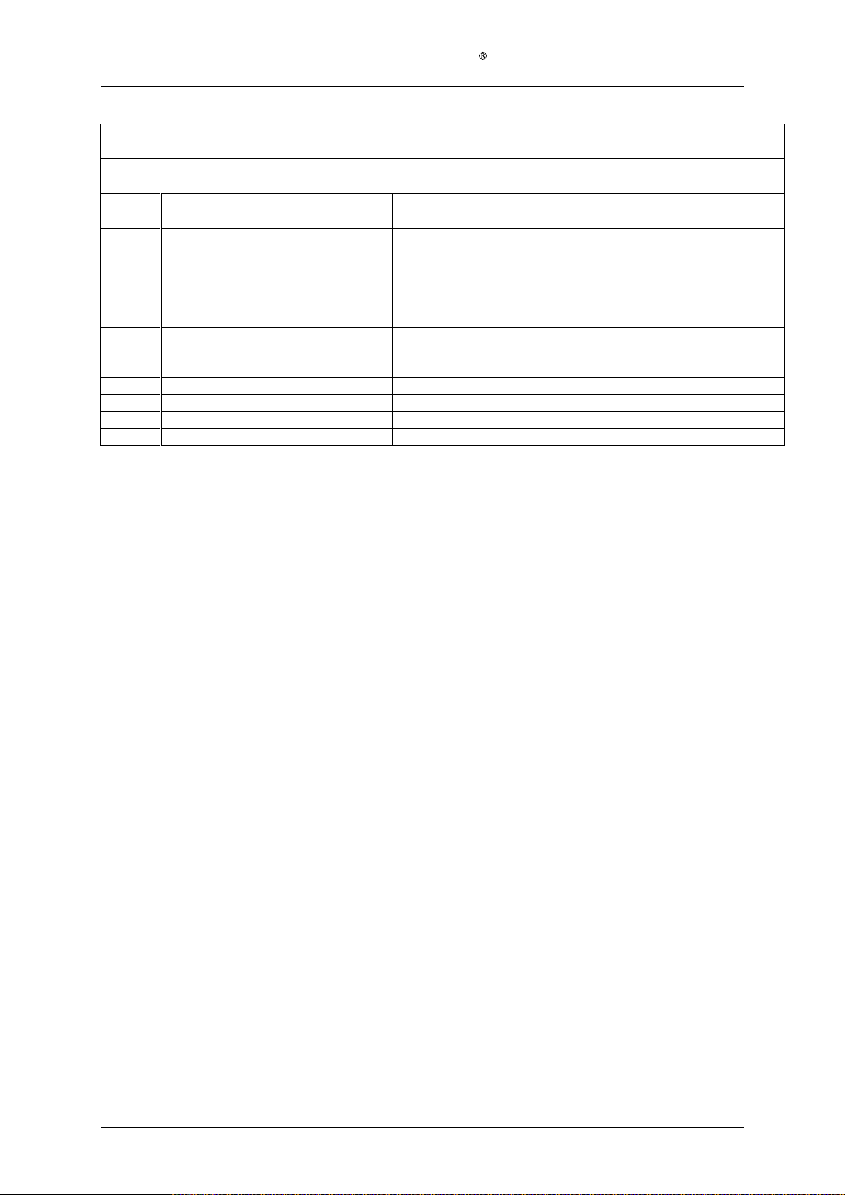
NOTE: Refer to the instructions above before using the table
Obstruction of cooling air inlet/outlet
or
Device internal error
Obstruction of cooling air inlet/outlet
or
Device internal error
Obstruction of cooling air inlet/outlet
or
Device internal error
Device internal error
Device internal error
Device internal error
Device internal error
Possible Causes
CL16
Aktilite CL16
Self-test too high en
Self-test too high LED driver temperature error.
Self-test too high LED array temperat
Self-test watchdog error. The software has been restarted.
Self-test too high LED current for OFF mode.
Self-test too high LED current for GUIDE LIGHT mode.
Self-test too high or too low LED current for FULL LIGHT mode.
Error Codes
Description
closure temperature error.
ure error.
Version 1.1
Page 18
of 18
 Loading...