

Page 1

S
S
S
e
e
e
C
C
C
r
v
r
v
r
v
o
o
o
i
i
i
l
l
l
c
c
c
o
o
o
e
e
e
u
u
u
M
M
M
r
r
r
T
T
T
a
a
a
V
V
V
n
u
n
u
n
u
a
a
a
l
l
l
Page 2

9
CHASSIS: 5P60
2
MODEL:
CT-34TP9ATS
Model No: CT-34TP9ATS
Version 1.0
Page 3

3
CONTENT
SAFETY NOTICE ...................................................................................................................................4
TECHNICAL SPECIFICATION ............................................................................................................. 5
GENERAL SPECIFICATION................................................................................................................. 6
CHASSIS BLOCK DIAGRAM ............................................................................................................... 7
CHASSIS WIRING DIAGRAM............................................................................................................ 17
PBC BOARD ......................................................................................................................................... 18
SERVICE ADJUSTMENT .................................................................................................................... 21
MECHANICAL DISASSEMBLY......................................................................................................... 30
SCHEMATIC DIAGRAM..................................................................................................................... 32
THROUBLE SHOOTING CHART ....................................................................................................... 34
Model No: CT-34TP9ATS
Version 1.0
Page 4

4
SAFETY NOTICE
SAFETY PRECAUTIONS
1. An isolation transformer should be connected in the power line between the receiver and the AC
line when a service is performed on the primary of the converter transformer of the set.
2. Comply with all caution and safety-related notes provided on the cabinet back, inside the cabinet,
on the chassis or the picture tube.
3. When replacing a chassis in the cabinet, always be certain that all the protective devices are
installed properly, such as control knobs, adjustment covers or shields, barriers, isolation resistorcapacitor network etc. Before returning any television to the customer, the service technician must
be sure that it is completely safe to operate without danger of electrical shock.
X-RADIATION PRECAUTION
The primary source of X-RADIATION in television receiver is the picture tube. The picture tube is
specially constructed to limit X-RADIATION emissions. For continued X_RADIATION protection,
the replacement tube must be the same type as the original including suffix letter. Excessive high
voltage may produce potentially hazardous X-RADIATION. To avoid such hazards, the high voltage
must be maintained within specified limit. Refer to this service manual, high voltage must be
maintained within the specified limits.
PRODUCT SAFETY NOTICE
Product safety should be considered when a component replacement made in any area of a receiver.
Components indicated by mark ! in the parts list and the schematic diagram designate components in
which safety can be of special significance. It is particularly recommended that only parts designed on
the parts list in this manual be used for component replacement designated by mark !. No deviations
from resistance wattage or voltage ratings may be made for replacement items designated by mark !.
Model No: CT-34TP9ATS
Version 1.0
Page 5

TECHNICAL SPECIFICATION
FEATURES
• Hyper-Band Tuner
• 100-Channel Memories
• NTSC Playback
• Front or Side AV Input
• Rear AV Input/Output
• S-Video Input
• On-Screen display
• Sleep Timer
• Auto Search/Store/Shut-off
• Full Function Remote Control
• 8W x 2 Speakers
• 772 (W) x 595 (D) x 856 (H) mm
• Weight: 78Kg
• Options
o DVD-Component Input
o Fastext
o MTS
o NICAM/German Stereo
o Wide Power Supply
Model No: CT-34TP9ATS
Version 1.0
5
Page 6
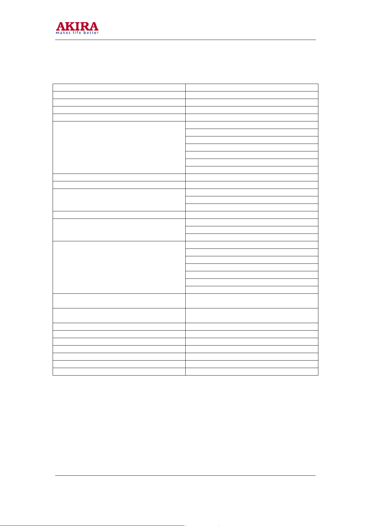
GENERAL SPECIFICATION
POWER CONSUMPTION 150W MAX
STANDBY POWER CONSUMPTION 5W
RECEIVER SYSTEM D/K; I; B/G; M
COLOUR SYSTEM PAL/ SECAM / NTSC
VISION INTERMEDIATE FREQUENCY 38.9MHz
INTER-CARRIER FREQUENCY
CHROMA IF FREQUENCY PAL/NTSC 34.47 / 35.32 MHz
ANTENNA TYPE DIN TYPE 75 OHM
CHANNELS RECEIVING
TUNING SYSTEM VS TUNING
AV IN/OUT
AV IN/OUT SPECIFICATION
OSD LANGUAGE ENGLISH, RUSSIAN, IRANIAN, ARABIC,
TELETEXT LANGUAGE PAN-EUROPEAN, CYRILLIC 2, IRANIAN,
AUDIO OUTPUT POWER >5W (1KHz, 0.5v INPUT, 10% THD)
SAFETY AUTHENTICATION STANDARD CB/ CE
LED INDICATOR POWER ON
HAND SET TYPE HS08 HS09
HAND SET POWER SUPPLY BATTERY 3V UM-3/R6/AA x2
COLOUR PICTURE TUBE 25” – 38” 110 DEGREE TUBE
REMOTE CONTROL DISTANCE 5m
4.5 MHz (M)
5.5 MHz (B/G)
6.0 MHz (I)
6.5 MHz (D/K)
5.85 MHz (NICAM B/G, D/K)
6.55 MHz (NICAM I)
5.74 MHz (GERMAN STEREO)
VHF-1 A-0; E2-E4; S1-S9 CH 44.25-161.25 MHz
VHF-2 S10-S41; E5-E12 CH 168.25-163.25MHz
UHF E21-E69 CH 471.25-863.25 MHz
1 AV IN+1 AV OUT; 1 FRONT AV INPUT
1 S-VIDEO IN, 1 YUV IN (OPTION);
21 PIN SCART (OPTION)
Y/C IN-----y 1.0 0.2V
VIDEO IN ----1.0 0.2V
AUDIO IN ---- 0.2V (r.m.s)
VIDEO OUT ---- 1.0 0.2V
AUDIO OUT ----0.2V (r.m.s)
RGB IN: -----0.7V
YUV ---- Y 1.0V
ITALIAN, TURKIC, GERMAN, FRANCE
ARABIC
p-p
; U 0.7V
p-p
p-p
75 ohm c: 0.7V
75ohm
p-p
75ohm
p-p
; V 0.7V
p-p
p-p
p-p
75 ohm
6
Model No: CT-34TP9ATS
Version 1.0
Page 7
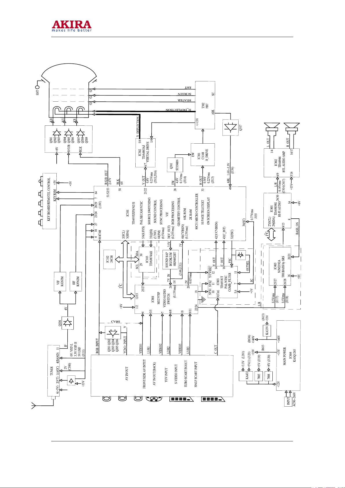
CHASSIS BLOCK DIAGRAM
Model No: CT-34TP9ATS
Version 1.0
7
Page 8
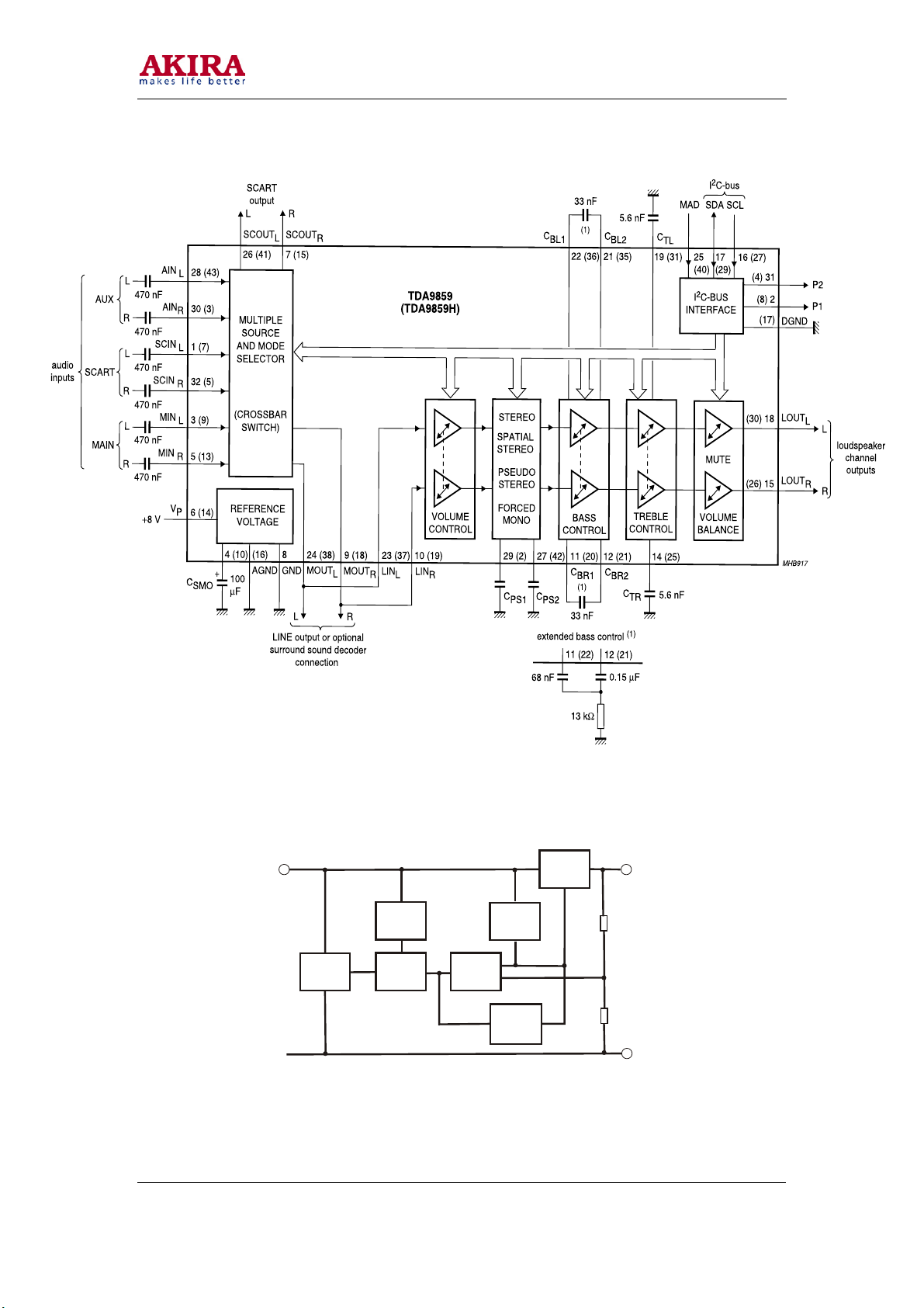
IC 401 (UNIVERSAL HI-FI AUDIO PROCESSOR) TDA9859H
IC605. IC606 <REGULATORS> L7800 SERIES
Model No: CT-34TP9ATS
Version 1.0
INPUT
1
REFERENCE
VOLTAGE
STARTING
CIRCUIT
CURRENT
GENERATOR
REFERENCE
VOLTAGE
ERROR
AMPLIFIER
SOA
PROTECTION
THERRMAL
PROTECTION
SERIES
PASS
ELEMENT
OUTPUT
GND
2
3
8
Page 9
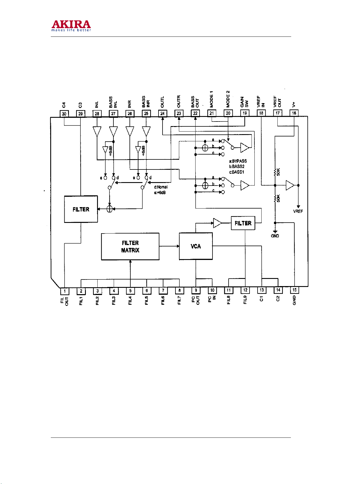
IC 402 (SRS TRUBASS) NJM2192 AM
9
Model No: CT-34TP9ATS
Version 1.0
Page 10
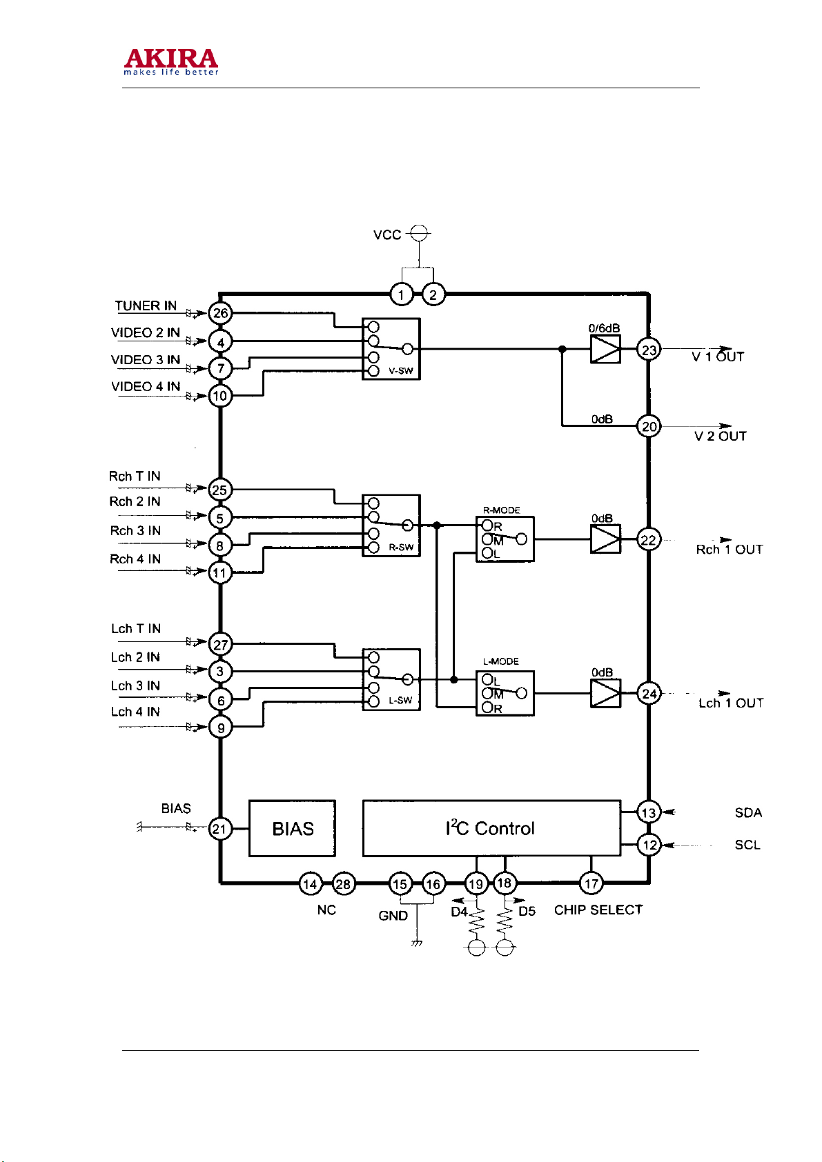
IC 401 (AV SWITCH W/IIC BUS CONTROL) M52797SP
10
Model No: CT-34TP9ATS
Version 1.0
Page 11

IC 101 (SYSTEM TV SIGNAL PROCESSOR-TELETEXT)
TDA93XXPS/N2/5I
Model No: CT-34TP9ATS
Version 1.0
11
Page 12

IC 103 (DIGITAL TV SOUND DEMODULATOR / DECODER)
TDA9874AH
Model No: CT-34TP9ATS
Version 1.0
12
Page 13

IC 302 (VERTICAL DEFLECTION BOOSTER) (TDA4863AJ)
IC 404(BTL AUDIO AMPLIFIER)(TDA8944J)
Model No: CT-34TP9ATS
Version 1.0
13
Page 14

IC 803(MULTISTANDARD COMB FILTE) (TDA9181T)
IC 802(HEF4052)
Model No: CT-34TP9ATS
Version 1.0
14
Page 15

IC 601 <PHOTO TRANSISTOR> TLP621
1
2
1:ANODE
2:CATHODE
3:EMITTER
4:COLLECTOT
IC 604 <POWER SWITCH> KA5Q12XXRF
Model No: CT-34TP9ATS
Version 1.0
TLP621
4
3
15
Page 16

Transistor Mark
E
PNP
A96
6
C
PNP
A10
1
5
E
C
PNP
A10
1
3
B
B
E
C
PNP
B
7
7
4
B
E
C
NPN
C22
3
0
E
B
C
NPN
B
4
2
0
B
E
C
NPN
C
2
482
B
E
C
B
PNP
E
NPN
C270
3
B
E
C
C
2
1
2
0
B
C
NPN
B
PNP
E
C
C
2
2
1
6
E
B
4
2
1
B
NPN
E
C
C
1
8
1
5
B
NPN
C
2
7
1
7
B
E
C
C
Vout SENSE
P5NK50Z
G
D
S
Se140
COLLECTOR
GROUND
B
INPUT
C5148
C
L7809
GND
E
OUTPUT
INPUT
S3904
B E
GND
L7812
GND
C
OUTPUT
OUTPUT
INPUT
L7805
OUTPUT
GND
-14-
Page 17

CHASSIS WIRING DIAGRAM
TO FRONT VIDEO IN
TO FRONT AUDIO IN
CN 806
TO CN 705
CN 803
TO CN 704
CN 802
CN 701
CN 801A
TO CN 703
CN 301
CN 805
TO CN 706
CN 202
CN 203
TO KEYBOARD
TO H501
H501
FROM CN 203
CN 602
17
CN 703
FROM CN801A
CN 701
FROM CN802A
CN401B
CN 601
CN 706
FROM Cn805
+H403
FOCUS
SCREEN
H502
FROM CN 302
CN401A
Model No: CT-34TP9ATS
Version 1.0
Page 18

PBC BOARD
Model No: CT-34TP9ATS
Version 1.0
18
Page 19

CAM350 PRO V 6.0 : Wed Jan 15 10:17:54 2003 - (Untitled)
19
Model No: CT-34TP9ATS
Version 1.0
Page 20

SIDE FRONT AV & AV PCB TOP LAYER
CONTROL PCB TOP LAYER
Model No: CT-34TP9ATS
Version 1.0
5800-D25TMY-01
20
Page 21

SERVICE ADJUSTMENT
1. Please notice the following before debug and equipment
a. The main power is 90~260V/50/60Hz. Please be careful when you debug and equip.
b. Don’t short any two soldering points, which should not be shorted and don’t touch
any component, which should not be touched.
c. Pls pull out plug before equipment.
d. For safety reasons, all components equipped or replaced should be identical with
BOM.
e. Must be warm up for 30 minutes or more and degauss CRT thoroughly with
demagnetizer before alignment.
f. The data of EEPROM must be stored before the adjustment for main chassis.
2. Tools and equipments for adjustment
a. Small “-” screwdriver.
b. Screwdriver without inductance.
c. Pattern Generator.
d. DC regulator power supply.
e. Digital Voltmeter.
f. Sweep signal generator.
g. 20MHz 2-channel Oscilloscope.
h. Signal condition
ITEMS LOGO PICTURE
1 CHN-
2 USA-
3 WE-6CH 182.25MHz RED FIELD PAL--BG L: R:
4 CH12 205.25MHz CROSS HATCH NTSC/M 1KHz
5 CHN-
6 224.25 PHILIPHS
7 WE-
8 CHN-
9 489.25 MONOSCOPE NTSC 1KHZ
10 751.25 MOMOSCOPE PAL--I A: BTSC
3. Power adjustment
Connect a 100W bulb cross C616. Then connect AC 220V power to CN601. If the bulb light,
the voltage is prescriptive, and there is no unconventionality, then the power is OK, else be
repaired.
Model No: CT-34TP9ATS
Version 1.0
CARRIER
49.75 PHILIPHS
1CH
61.25 COLOR BAR NTSC--M 1KHz
3CH
216.25 GREY/COLOR
12CH
294.25 HALF COLOR
S20CH
471.25 CROSS HATCH PAL--D/K 1KHZ
13CH
PATTERN SYSTEM SOUND
PICTURE
BAR
PICTURE
BAR
REMARK
MODE
PAL--I 1KHz
A2 STEREO
400HZ
SECEM -D/K
PAL--BG A: BTSC
PAL--BG A: 400HZ
BTSC
B: MUSIC
C: 1KHZ
B: 1KHZ
B: MUSIC
C: 1KHZ
/TELETEXT
B/G NICAM
STEREO
I NICAM
21
Page 22

4. Complete machine general adjustment.
a. Go to factory mode before warm up line.
Method: Press key CLOCK, P.M., , TV SET will go to factory mode. Press key 0-9
to entering factory menu. Select the item by “PROG+” and “PROG-“ keys. Adjust by
“VOL+” and “VOL-” Keys. Press “ + ” key to exit factory mode.
b. Focus adjustment.
i. Receive monoscope pattern.
ii. Set TV to work in dynamic status.
iii. Adjust the focus knob of FBT to get the clearest picture.
c. Screen Voltage Adjustment (KEY 0)
i. Set TV at “TV” “STANDARD” mode, no signal input.
ii. Press key CLOCK, P.M. in turn to entering factory mode.
iii. Press 0 key.
iv. Adjust the screen knob of FBT to get a horizontal faintness beam line.
v. Press other keys to go to the normal work status.
d. Vertical size and pin cushion adjustment (KEY 2)
i. Receive 50HZ cross hatch pattern. Set TV standard status, adjust 5VSL to
obtain half of the cross hatch, adjust 5SCL to obtain picture’s vertical pin
cushion a good status, adjust 5VSH to obtain picture’s vertical center at the
center of CRT screen in factory mode.
ii. Receive 50HZ monoscope pattern. Set TV standard status,. Adjust 5VAM to
obtain picture’s vertical redisplay ratio more than 90% in factory mode.
Vertical slope 50Hz 5VSL
Vertical amplitude 50Hz 5VAM
S-correction 50Hz 5SCL
Vertical shift 50Hz 5VSH
iii. Receive 60HZ cross hatch pattern. Set TV standard status. Adjust 6VSL to
obtain half of the cross hatch, adjust 6SCL to obtain picture’s vertical pin
cushion a good status. Adjust 6VSH to obtain picture’s vertical center at the
center of CRT screen in factory mode.
iv. Receive 60HZ monoscope pattern. Set TV standard status. Adjust 6VAM to
obtain picture’s vertical redisplay ratio more than 90% in factory mode.
Vertical slop 60Hz 6VSL
Vertical amplitude 60Hz 6VAM
S-correction 60Hz 6SCL
Vertical shift 60Hz 6VSH
v. If necessary, adjust Horizontal Center and EW again.
vi. Receive 50HZ RGB or YUV cross hatch pattern. Set TV standard status.
Adjust 5RGH to obtain picture’s vertical center at the center of CRT screen
in factory mode. (OPTION).
vii. Receive 60HZ RGB or YUV cross hatch pattern. Set TV standard status.
Adjust 6RGH to obtain picture’s vertical center at the center of CRT screen
in factory. (OPTION).
22
Model No: CT-34TP9ATS
Version 1.0
Page 23

e. Horizontal Center and EW adjustment (KEY 1)
i. Received 50HZ monoscope PATTERN. Set TV standard status. Adjust
5HSH to obtain horizontal center at the center of CRT screen.
ii. Receive 50HZ cross hatch pattern. Set TV standard status. Adjust 5EWW,
5PWW, 5UCR, 5LCR, 5PAR, 5BOW, 5EWT to obtain picture’s Horizontal
redisplay ratio more than 90% in factory mode.
Horizontal parallelogram 50Hz 5PAR
Horizontal bow 50Hz 5BOW
Horizontal shift 50Hz 5HSH
EW width 50Hz 5EWW
EW parabola /width 50Hz 5EWP
EW upper corner parabola 50Hz 5UCR
EW lower corner parabola 50Hz 5LCR
EW trapezium 50Hz 5EWT
iii. Receive 60HZ monoscope PATTERN. Set TV standard status. Adjust
6HSH to obtain horizontal center at the center of CRT screen.
iv. Receive 60HZ cross hatch pattern. Set TV standard status. Adjust 6EWW,
6PWW, 6URC, 6LCR, 6BOW, 6EWT to obtain picture’s Horizontal
redisplay ratio more than 90% in factory mode.
Horizontal parallelogram 60Hz 6PAR
Horizontal bow 60Hz 6BOW
Horizontal shift 60Hz 6HSH
EW width 60Hz 6EWW
EW parabola/ width 60Hz 6EWP
EW upper corner parabola 60Hz 6UCR
EW lower corner parabola 60Hz 6LCR
EW trapezium 60Hz 6EWT
f. OSD position adjustment.
i. Menu OSD position adjustment. Received 50/60Hz cross hatch pattern. Set
TV standard status. Press KEY 2 in factory mode, adjust 5VOF /6VOF and
HOF item, to obtain menu OSD at the center of CRT screen.
ii. LOGO position adjustment. Receive 50/60Hz cross hatch pattern. Set TV
standard status. Press KEY 7 in factory mode, adjust XMIN, XMAX,
YMIN, and YMAX item, to obtain LAGO at the center up to 1/3 of CRT
screen.
iii. TELETEXT OSD position adjust. Received 50/60HZ TELETEXT signal.
Set TV standard status. Press KEY 7 in factory in factory mode, adjust
TXMI and 5TYM/6TYM item, to obtain INDEX at the center of CRT
screen.
g. White Balance adjust (Applied in factory) (KEY 3)
i. Normally, 5P60 can auto adjust white balance, but for some CRT need to
adjust white balance carefully by hand. Set BRIGHTNESS and
CONTRAST at normal status, receive GREY SCAL and entering factory
mode press KEY 3, set WPR at 31, adjust WPG and WPR to obtain white
balance.
Model No: CT-34TP9ATS
Version 1.0
23
Page 24

h. RF. AGC adjustment (KEY 4)
i. Receive 60dB RF signal. Connect Digital voltmeter positive terminal to
tuner AGC terminal and negative terminal to GND.
ii. Entering the AGC item in factory mode by the REMOTE CONTROL.
Metod. Press key CLOCK, P.M. inturn, you can enter into factory mode,
then press key “4” and select AGC item by PROG+/-.
iii. Adjust “VOL+” and “VOL-” keys to obtain 3.8V Digital voltage meter
reading or just no NOISE on screen.
iv. Press key “ + ” to exit factory mode.
i. E2PROM initialization
i. When in repairing, we can replace E2PROM by other empty or unempty
E2PROM, but you must initialize E2PROM to avoid unknown things.
ii. Methods:
1. Press remote control KEY CLOCK, P.M. in turn to entering
factory mode.
2. Press remote control KEY 8 to entering INIT menu, then press key
PROG +, you can see “INIT BUSY” waiting for about 5 seconds
till “BUSY” disappeared, then POWER OFF and ON by main
power E2PROM initialization in completed.
iii. Setting the data in E2PROM. When in manufacturing, first you read the data
from an good E2PROM 24C08, then WRITE to other E2PROM 24C08.
24
Model No: CT-34TP9ATS
Version 1.0
Page 25

Service items
This appendix shows information about service items that are available. The table list all possible
available service items with its.
25
Model No: CT-34TP9ATS
Version 1.0
Page 26

26
Model No: CT-34TP9ATS
Version 1.0
Page 27

27
Model No: CT-34TP9ATS
Version 1.0
Page 28

28
Model No: CT-34TP9ATS
Version 1.0
Page 29

PURITY ADJUSTMENT
1. Before color purity adjustment, warm up the TV set over 15 minutes and fully degauses.
2. Receive pure white signal in AV status and set the TV receiver dynamic.
3. Go to factory mod MENU2. After write down the values of R-BIAS and B-BIAS, set the
values of R-BIAS and B-BIAS zero.
4. Loosen the clamp screw of the deflection yoke and pull the deflection yoke towards color
purity Magnetic loop.
5. Adjust color purity magnetic loop to make the green area at the center of CRT screen.
6. Slowly push the deflection yoke toward the front of CRT and set it where a uniform green
field is obtained. Tighten the clamp screw of the deflection yoke.
7. Restore the values of R-BIAS, G_BIAS and B-BIAS.
CONVERHENCE ADJUSTMENT
1. Receive a dotted pattern. Set the TV receiver dynamic.
2. Loose the convergence magnet clamper and align red with blue dots at the center of the screen
by rotating (R, B) static convergence magnets.
3. Align Red/Blue with green dots at the center of the screen by rotating (RB-G) static
convergence magnet.
4. Remove the DY wedges and slightly tilt the deflection yoke horizontally and vertically to
obtain the good.
Model No: CT-34TP9ATS
Version 1.0
29
Page 30

MECHANICAL DISASSEMBLY
Cabinet back removal
1. Refer to figure 1, remove 10 screws.
2. Pull off cabinet back and remove.
Chassis removal
1. Remove cabinet back.
2. Discharge the picture tube anode (2
lead).
3. Disconnect Degaussing coil socket (KE), picture tube socket, Deflection yoke connector
(KDY), speaker connectors (KL and KR) and 2
4. Remove chassis completely by sliding it straight back.
DEGAUSSING
COIL
DEGAUSSING
COIL SOCKET
nd
anode lead) to the dag coating (picture tube grounding
nd
anode lead.
DEGAUSSING
COIL HOLDER
PICTURE TUBE
GROUNDING LEAD
To CRT Unit
ground
30
Model No: CT-34TP9ATS
Version 1.0
Page 31

31
Picture tube removal
CAUTION: Do not disturb the deflection yoke or magnet assembly on the picture tube Neck. Care
must be taken to keep these assemblies intact, unless picture tube is being replaced. Discharge the
picture tube to the coating before handling the tube.
1. Remove chassis, referring to chassis removal instructions.
2. Place cabinet front face down on the soft surface.
3. Remove the screw on each corner of the picture tube and GENTLY lift the picture tube out of
the cabinet.
4. Install a replacement picture tube in reverse order. Properly install the degaussing coil and
picture tube grounding lead on the picture tube. See Figure 2.
Note: If picture tube is being replaced, mount the Degaussing Coil on the picture tube. See following…
4
6
Model No: CT-34TP9ATS
Version 1.0
2
3
1
5
10
9
Page 32

R802
NOTE: ACTIVE AREA , NO TOUCH WITH PERMITTION
1
CN601
H602
DEGAUSSING
H602
CN601
2
1
AC220V
5P60 SCHEMATIC DIAGRAM
TUNER
LED801
LED801
11
13
15
17
19
21
1
1
Q801
C2120
+
_
CN708
AV3
P701
U/AV3_L
P702
V/AV3_R
P703
SCART2
1
3
5
7
9
2
2
C801
47u
1
2
Y/AV3
A_ro
A_rin
A_lo
GND
B_G
A_lin
B
ID
G_G
NC
Green
NC
R_G
GND
R
BL
G
GND
Vo
Vin
G
4
DL601
JQX-14F
SW601
C802
220P
X801
C803
220P
C804
0.1u
CN702 CN702A
YUV AV3_AUDIO
12345
2
4
6
8
10
12
14
16
18
20
CN705
123
CON4
AV
L
R
RT601
10
D611
IN4148
CRYSTAL
L
R
1
3
5
7
9
11
13
15
17
19
21
Gnd
R600
2.2M/0.5W
F601
5.0AL/AC250V
Q613
C1815
1
2
3
4
5
6
7
8
9
6
Gnd
SCART1
A_rin
GND
A_lin
GND
GND
R149 10K
1N4148
D104
Q110
C2216
+33V
REMOTE CONTROL
D6
D7
S2
S1
REM
IC801A
UPC6134
VDD
X-OUT
X-INT
GND
RESET10K0
P706
P707
1
2
3
4
5
6
CN706
CON6
A_ro
2
A_lo
4
B_G
6
B
8
ID
G_G
10
NC
Green
12
NC
R_G
14
R
16
BL
G
18
Vo
20
Vin
G
CN204
1
CON2
2
1
CN202
2
CON3
3
R601
4.7 NTC
C603
220nF/275VAC
T602
15mH X 2
C602
220nF/275VAC
T601
15mH X 2
C601
220nuF/275VAC
C628
47u/25V
+
Gnd
XG6VS96A
TUNER
AGC1VT2Hi/n.c.3Mi/BS1(SCL)4Lo/BS2(SDA)5V+6i.c.(V+)7i.c.8i.c.(+33V)9IFGND10IF
R147
R148
39K
39K
+
C104
C100
C134
10uF
47nF
47nF
R146
180
+ C128
100uF
Gnd
A
B
C
20
D5
D
19
D4
E
18
D3
F
17
D2
G
16
D1
H
15
D0
123456
14
K3
13
K2
12
K1
11
YC
CN801
CN701
CON8
CON6
8
1
7
2
6
3
5
4
4
5
3
6
2
1
CN703
CON8
1
CN802
2
CON6
3
4
6
5
5
6
4
7
3
8
2
1
CN803
1
CON2
2
2
CN704
1
CON2
2
1
CN806
CON2
TV_OUT
BRIDGE
KBJ6J
C604A
2200pF/1KV
7
C604B
2200pF/1KV
R602
2
120K/2W
BA158
D600
3
1
5
4
KA5Q12XRF
2
IC604
KA5Q12XRF
R612
ZD602
+
10K
C627
JJ
R611
220u/25V
47K
5.0V
+
R102
C101
27K
220uF
39K
R103
C102
R106
C105
100nF
4.7K
10nF
R101
Gnd
100K
L: VL
R166
C132
M: VHF
470
100P
H: UHF
AGCTUNING
BAND
K0 K1 K2 K3 S1 S2
ST
D0
1
2
D1
6
D2
+
0
D3
VDD
AV/TV
D4
TUNE
SETUP
D5
D6
R806
D7
100K
R844
1.8K
R840
75
Gnd
OPT:(Video status)
RGB
Internal: 0.0...2.0 V
BLK
OPT
External (16:9): 4.5...7.0 V
External (4:3): 9.5...12.0 V
BLK:(RGB status)
Internal: 0.0...0.4 V
External: 1.0...3.0 V
R831
1K
R834
47K
R836
R828
75
1K
R835
47K
R821
CVBS_L
1K
R822
47K
CVBS_IN
R811
75
R819
CVBS_R
R8181K
47K
R812
IN1_L
1K
AV1_IN
R810
75
R817
IN1_R
1K
R826
Gnd
4.7K
123
CN805
OUT-R
OUT-L
CON3
POWER
T604
9
+
C604D
*C606
2200pF/1KV
330uF/420V
8
7
C604C
2200pF/1KV
L601
61115
L5MM
4
1
R605
10
D601
BA158
D603
2
+
BA158
C613
47u/50V
R604
BCK-50-0223
620
C607
2200pF
D602
IN4148
C608
0.01
ZD601
R603
4.7V
C611
C610
470
3.3n
22n
C609
47n
Gnd
+5V
+5V
PHILIP S CODE
SYS
VOL+
5
S.M
MENU
SOUND
PIC
Q.VIEW
Q804
S3904
R843
47K
SW_C
C814
100u
IN2_L
AV2_IN
IN2_R
R827
4.7K
R818
4.7K
TLP621
IC601
R617 8.2M/1W
1
C612
2200pF/AC275V
C106
10nF
L101
10uH
I/II
VOL-
4
9
TEXT
R821
R813
4.7K
IF
11
R120
75
C108
10nF
R132
1K
PROG-
PROG+
MUTE
3
7
8
-/--
P.M
GAME
CLOCK
+8V
(VIDEO/AUDIO SWITCHING)
C815
0.01u
1
VCC
+
7.9V
2
VCC
7.9V
3
C816 1u
Gnd
Gnd
+
IN2 L
4.2V
4
C817
+
AV2 IN
0.47u
3.2V
C818 1u
5
+
IN2 R
4.2V
C819 1u
6
+
IN3 L
4.2V
C821
7
+
AV3 IN
0.47u
3.2V
8
C822 1u
+
IN3 R
4.2V
9
C803 1u
+
IN4 L
4.2V
C823
+
AV4 IN10D4
3.2V
0.47u
C804 1u
11
+
IN4 R
4.2V
12
SCL
R816
4.7K
4.7K
3.3V
R813
13
SDA
100
3.2V
14
NC
R814
0V 0V
100
SDASCL
L602
18
L5MM
D605
RU4A
C616
100uF/200V
17
16
Gnd
C619
1000p/2KV
R613
14
2
0.33
13
12
Gnd
R610
2
0.33
10
C623
Gnd
*R609
8.2K
IC602
SE120
R607
1K
D604 BA158
C615
1nF
Gnd
C139
100uF
R133
4.7K
C109
D608 RU4B
390P/500V
Gnd
Gnd
R135
C110
4.7nF
R130
1.8K
OPTION
COMB_FILTER
Y/CVBS
IC801
M52797SP
CHIP SELECT
C617
220p/2KV
L603
120uH
+
Gnd
C622
D607
RU3YX
1
2
3
+
L212 10uH
L211 10uH
R841
47
390p/500V
RD2
RD3
RD4
RD52KRD6
5.6K
3.3K
2.7K
1.5K
SW2 SW3 SW4 SW5 SW6 SW7 SW8SW1
+8V
SAW102
R144
K9362M
4.7K
R136
10
12345
R137
C125
4.7K
Gnd
10nF
L104
SAW101
0.82uH
K6259K/K6263K
(K2962M/G3964M FOR CE)
C126
1
D103
BAT85
R141
4.7K
Q112
C2717
100u/16V
+
Gnd
AM_AUDIO
28
4.4V
27
4.2V
26
3.7V
25
4.2V
24
3.5V
23
3.0V
22
3.5V
21
3.7V
20
2.3V
19
4.4V
18
0.1V
17
0V
16
0V
15
+138V
+33V
IC103
ZD33V
+15V
+12V
Q602
A966
R635
2K
10
2
Gnd
C828 0.01u
C235 0. 1u
+
C240
C239
100u/16V
FBISO
FM_AUDIO
C809
+
1u
C811
+
0.47u
C808
+
1u
C807
+
1u
C805
+
1u
C804
+
10u
C806
+
1u
Gnd
SW_C
+33V
+140V
2
R633
+
Gnd
R619
2.2/2W
R636 6.8/2W
100u/35V
R451
47K
R618
5.6K
3
8
Gnd
SYSTEM
R143
47K
IC803
TDA9181T
1
Cin
1V
2
INPSEL
5.3V
3
Y/CVBS2
1.7V
4
DGND
0V
5
Gnd
VDDD
5.2V
6
VCCA
5.2V
7
SC
0.5V
FSCSEL8FSC
0V 0.6V
R242
100
TV_L
TV_R
TV_IN
R824
390
C823
1u
R823
470
Gnd
Gnd
+5V
R842
10K
R820
10K
Y/CVBS
+15V
150/2W
2
R627A
22K/1W
C635
100uF/50V
R630
2
220/2W
2
R627
150/2W
C618
In Out
2
+
Gnd
C621
100u/35V
Gnd
In Out
2
+
Gnd
C620
Gnd
Q604
3094
4
5
IF2
IF1
SIF2
SIF1
SYSTEM
+8V
C236
1nF
R238
16
Cout
10K
1.5V
15
OUTSEL
Q216
R239
5.0V
3904
14
47K
Y/CVBSout
1.5V
13
AGND
C238
0V
47pF
12
Y/CVBS1
1.3V
R245 10K
Gnd
11
SYS1
0.4V
Q215
10
SYS2
3904
5.0V
9
R235
C245
10K
0.01u
+8V
+8V
C824
+
100u
R830
47K
Gnd
+
Q801
J805
S3904
22
V
TV_OUT
Y
C827
R829
R833
1.8K
Y_OUT
R624
3.3K
R625
10K
R622
1K
R623
1K
U
220u/16V
270
Q803
S3904
OUT_L
C801/C803
+5V
0.22u
+8V
Gnd
AUDIO_L
AUDIO_R
+8V
Q802
S3904
C802
OUT_R
R832
0.22u
1.8K
Gnd
Q606
REF3A
KA431
Q605
REF3A
KA431
IC605
7808
IC606
7805
Gnd
R626 47K
Q607
3094
K
K
+
C633
220uF/16V
+
C630
220uF/16V
+3.3V
2
1
2
1
+8V
+5V
C436
0.1uF
R452
>1V WORKING
<0.7V STANDBY
SYS
+8V
100uF
+3.3V
+
C634
10uF/50V
Gnd
+5V_A
+
C625
10u/50V
Gnd
+8V
+5V
STANDBY
Gnd
47K
10nF
Q106
C2717
R134
100
C_IN
+5V
Y/CVBS
ZD801
5.1V
Gnd
+8V
NC
TV_L IN
TV IN
TV_R IN
OUT L
AV OUT
OUT R
BIAS
V2 OUT
D5
GND
GND
R639
0.33/3W
3
C631
+
100uF/200V
+
C626
1000uF/25V
Gnd
+
C624
1000uF/25V
Gnd
R631
2.7K
Q608
3094
Gnd
TUNING
R237
47k
FROM IC801
M52797
SYS:PAL/NTSC
L: PAL
H: NTSC
FSC_9Pin
COMB:
R236
2.3V+FSC;
10K
Y/C: +5V
BYPASS: 0V
FSC
AV1
AV2
C?
0.01uF
IC802 HE F4052
9
2 TO 4
Decoder
A1
0.1V
10
A0
5.0V
11
0V
12
0V
2
13
1
0V
0
14
0V
15
0V
Gnd
+8v
16
Vdd
+
7.7V 2.6V
C233
Gnd
OPTION
TRUBAS S
R421 27K
C421
0.1
R423 3.3K
C422
0.1
R420 47K
C423
0.1
R422 8.2K
C425
0.1
R424 8.2K R426 1.8K
+
C439
10uF
Gnd
Gnd
+3.3V
+5V
R1
4.7k
R2
4.7K
STANDBY
SCL
SDA
AV1
AV2
KEY
GRAD
BAND
SYSTEM
+8V
+8V
C_out
Y_out
220uF/16V
EW
VDRB
VDRA
IF1
IF2
AGC
SIF1
SIF2
C172
22nF
C127
FSC
C?
C?
0.01uF
0.01uF
R?1KR?1KR?
8
Vss
0V
7
Vee
0V
L209 10uH
6
E
0V
X205
XT-6.5
5
L208 10uH
2.3V
3
4
X205
3
2.6V
XT-6.0
2
3
1
2.0V
0
L206 10uH
2
2.6V
X205
XT-5.5
1
L207 10uH
X205
XT-4.5
Gnd
1
FILOUT
4.0V
2
FIL1
4.0V
0.1
C430
3
FIL2
4.0V
4
C429
FIL3
BASINL
0.1
4.0V
IC402
5
R428 47K
FIL4
NJM2192A
4.0V
6
FIL5
BASSINR
4.0V
100K
R427
7
FIL6
4.0V
8
FIL7
4.0V
9
MOUT_R
BASSOUT
4.0V
10
PCOUT
MODE1
4.0V
C428 0.01
11
FIL8
MODE2
4.0V
12
FIL9
GAINSW
4.0V
C444 1u
13
+
C1
VERFIN
0V
14
C443 10u
+
C2
VREFOUT
0V
GND15V+
0V
C435
0.1uF
+5V
C160
10nF
C161
100p
Gnd
R213
+5V
2.7K
+3.3V
R9
100R7100
R5
R8
R4
R6
R10
R161
4.7k
4.7k
3.3K
4.7k
3.3K
Gnd
1
10K
2
3
4
5
6
7
R202
C200
8
ZD206
0.01uF
9
5.6V
Gnd
10
11
12
C162
13
Gnd
L112
10uH
C129
R162 100
R163 100
R164 100
R168
39K
R225
180
R224
180
R221
180
R219
180
C4
C3
INL
INR
OUTR
OUTL
220nF
14
C163
15
220nF
R145
C164
16
15K
2200pF
C131
+
100nF
Gnd
C171
100nF
Gnd
1K
Gnd
R217
10
Q212
3904
30
4.0V
29
4.0V
28
4.0V
27
4.0V
26
4.0V
25
4.0V
24
4.0V
23
4.0V
22
4.0V
21
0V
20
0V
19
0V
18
4.0V
17
4.0V
16
7.9V
+
Gnd
17
+
C165
C130
4700pF
18
1uF
+
C166
C138
19
100nF
2.2uF
20
21
22
23
24
25
26
27
28
29
+ C135
C168
10uF
2200P
30
C170
2200P
R222 3.3K
31
+
C173
330pF
C174
1.5nF
C124
C234
Gnd
+
2.2uF
4.7uF
QSS ONLY
CN204
V
1
Y
2
GND
3
U
4
CON4
+5v
+8V
R232
10
VIDEO_OUT
FROM UOC P38
R216
100
R218
180
Gnd
Q213
3904
TV_IN
R231
R229
1K
270
CVBSINT
TO UOC P40
R226
470
Gnd
0.01
C432
R430
C433
1K
0.01
AUDIO_L
Gnd
R432 3.3K
C447
1uF
AUDIO_R
C446
C445
1K
R429
R431
1uF
C448
1K
Gnd
Q405
S3904
R436 10K
Gnd
R437 10K
C437
+
10u
C438
+
10u
R433
10K
R438
+
10K
C440
R434
10u
Gnd
L402
C442
10uH
220u
+8V
RD7
RD81KRD9
1.2K
47
8
WP
Vdd
5.0V
0V
7
n.c.
PTC
0V
6
A2
SCL
3.3V
0V
5
Vss
SDA
3.2V
0V
C159
100pF
Standby
2.6V
SCL
3.3V
SDA
3.2V
Tuning
2.7V
AV1
0V
AV2
5V
Key/Led
3.3V
Status_AV
GRAD
0V
Vss C/P
0V
0V
Band1
System
M/L/L'
4.6V
VssA
0V
IC101
SECPLL
2.3V
TDA93XX/N2
Vp2
7.9V
PHILIP S UOC
DECDIG
5.0V
(TDA9363PS/N2
PH2LF
TDA9365PS/N2
3.5V
TDA9384PS/N2
PH1LF
TDA9386PS/N2)
3.9V
Gnd3
0V
DECBG
4.0V
AVL/EWD
4.8V
VDRB
AUDOUT/AMOUT
1.1V
VDRA
1.1V
IF1
1.9V
IF2
1.9V
IREF
3.9V
VSC
3.8V
Tuner AGC
1.7V
AUDEEM/SIF1
3.1V
DECSDEM/SIF2
2.3V
Gnd2
0V
SNDPLL/SIFAGC
2.2V
0V
AVL/REFO32H. out
L110
+5V
10uH
R171
10
L111
10uH
C113
1uF
Gnd
Gnd
Gnd
Gnd
Gnd
R128 100
TV_L
R123 100
TV_R
+5V
L106
10uH
L107
10uH
P2: MUTE
P1: BASS_CON
L: BASS IC On
H: BASS IC Off
Gnd
MUTE
+5V
R435
10K
Main_L
1u/N.P.
+
C406
100uF/16V
Gnd
C405
Main_R
1u/N.P.
+5V
12345
+CR1
10u/16V
RD11
1
24C08
IC102
2
3
4
Gnd
IRin
4.9V
STAT
0V
GRAD
0V
VddP
3.3V
Reset
0V
XTALout
XTALin
OscGnd
0V
VddC
3.3V
VpE
0V
VddA
3.3V
Bout
3.1V
Gout
3.1V
Rout
2.9V
Iblack
5.9V
BCLin
2.3V
B2/Uin
2.5V
G2/Yin
2.5V
R2/Vin
2.5V
Fblin
4.0V
3.3V
CHROMA
1.5V
CVBS/Y
3.7V
Gnd1
0V
CVBSINT
3.9V
Vp1
7.9V
IFVO/SVO
3.3V
PLLIF
2.4V
EHTO
1.7V
AUDEXT/QSSO
3.7V
FBISO
0.5V
0.6V
C178
1uF
Gnd
33
Sysclk
34
SCK
0.1V
35
Vddd3
5.0V
36
Vssd3
0.2V
37
P1
0V
38
MONOIN
N.C.
2.4V
39
N.C.
EXTIR
2.4V
40
N.C.
EXTIL
2.4V
41
C114
+
V_REF2
2.4V
47u
42
P2
0V
43
C112
OUTM
2.4V
0.01
Vssa4
44
0V
1
out_L
C115
0.01
R130
C116
0.01
2.2
Gnd Gnd Gnd Gnd
R131
10
44
1
n.c.
n.c.
0V
C408
2
Cps1
4.0V
0.01
3
AinR
4.0V
4
P2
4.0V
R405
5
SCinR
1.8K
0.4V
6
n.c.
0V
R404
7
SCinL
10K
4.0V
8
P1
2.8V
C407
9
MinL
4.0V
10
Csmo
7.8V
11
n.c.
0V
n.c.12MinR13Vp14SCoutR15Agnd16Dgnd17MoutR18LinR19Cbr120Cbr221n.c.
+
C403
220u/16V
Gnd
CN003
M001
CON5
(38K)
RR1 100
1K
LED001
R203 3.3k
C202
0.01u
Gnd
64
R201 10k
63
62
C217
61
100uF/16V
60
X101
C205
Gnd
59
12MHz
27pF
58
27pF
C206
57
C208
100nF
56
+
C216
100u
55
Gnd
54
R204 100
53
R205 100
Q202
52
3904
R206 100
Q203
51
3904
10K
R253 100
R207
50
R228 4.7K
49
220uF/16V
+
48
C218
ZD202
47
8V2
Gnd
46
45
FM
44
43
C235
42
0.01uF
41
40
Gnd
C230
0.22uF
39
38
R209
C212
37
C211
390
100nF
100nF
36
Gnd
gnd
35
QSS
R241
34
+8V
27K
33
Gnd
R212
1.8K
R211
27K
R210
C213
100K
0.1uF
SCL
SDA
R173
R174
100
100
R111
R110
10
Gnd
10
C177
27
32
29
31
26
28
0.7V0V0V
3.3V
3.5V
5.0V0V5.0V
WS
SCL
SDA30SDD
Vssa3
Vdda3
IC103
TDA9874
NICAM
outR2Vdda13Vssa14Vssd15Vddd16Vssd27n.c.8TP29Nicam
0V0V0V0V0V
0V
0V
2.4V
2.4V
4.8V
4.8V
C117
1uF
Gnd Gnd
Gnd Gnd Gnd
Gnd
C118
1uF
C411
C409
Gnd
0.01
43
40
41
39
38
0V
4.0V
4.0V
4.0V0V0V
4.0V
n.c.
Cps242AinL
MAD
MoutL
SCoutL
IC401
TDA9859
AUDIO CONTROL
0V
0V
4.0V
3.9V
7.9V0V4.0V
Gnd
C404
0.1uF
R403
L401
10uH
13k
Gnd
+8V
R536
220
R538
2
12K
D503
Q532
BA157
BF420
R531
Q531
C4544
22
Q533
R532
BF421
2.2K
R533
R534
R535
270
22
S-Gnd
ZD205
5.1V
R200
IRIN
100
OPT
+3.3V
L201 10uH
+
C204
100nF
Gnd
L202 10uH
L203
10uH
+
+8V
C215
100uF/16V
R255
39K
Gnd
Q201
3904
R251
100
R252
100
ZD203
C220
8V2
0.1nF
ZD204
R215 27K
Gnd
8V2
C224
100nF
C225
100nF
C226
100nF
FM_AUDIO
C_OUT
Y_OUT
CVBSINT
+8V
+
L205
10uH
C219
3.3uF/50V
VIDEO_OUT
FBISO
R330
EHTO
680K
H_OUT
QSS
L109
15uH
OPTION
C123
47p
Gnd
1uF
C176
0.1
23
24
25
2.0V
2.0V
0V
22
test1
Gnd
SIF1
0V
V_ref1
21
CRESET
Vdec
C122
0V
1uF
20
Vssa2
0V
19
ADDR2
Gnd
5.0V
18
I_ref
2.0V
R134
17
TEST2
8.2K
0V
16
TP3
0V
15
Gnd
XTALI
1.6V
14
XTALO
X101
1.6V
24.576MHz
13
ADDR1
5.0V
12
Pclk
0.5V
TP1 SIF2
11
10
C412
R408
68n
33nF
13k
37
34
4.0V
4.0V
4.0V
0V
Gnd
33
n.c.
n.c.
Cbl235Cbl136LinL
0V
32
n.c.
0V
C413
31
Ctl
4.0V
C414
30
LoutL
4.0V
1u/50v
29
SDA
3.2V
28
n.c.
0V
27
SCL
3.3V
C417
26
LoutR
1u/50v
4.0V
25
Ctr
4.0V
C418
24
5.6n
n.c.
0V
23
n.c.
Gnd
0V
R402
100
0V
4.0V
4.0V
4.0V
22
C401 33nF
(NO TRUBASS)
(P20-21,P35-36)
C401
0.15uF
C402
68n
CON6
H501
+8V
1
KB
2
3
CN203
CON6
4
5
1
2
3
4
5
6
D313
IN4148
U
Y
V
BLK
B
G
R
5.6n
C415
100p
Gnd
C416
100p
S-Gnd
6
+8V
ZD501
8V2
ABL
R503
1K
+8V
VDRA
VDRB
EW
H
FBISO
R331
1
4.7K
ZD303
8V2
C304
4700p
Gnd
C326
4.7u/250V
2
+
R621
3.3K/7W
Gnd
C2482
H_OUT
Q304
C313
2200pF/500V
R310
100
R302
R313
C314
2.7K
1K
100p
Gnd
R306
220K/0.5W
CN302
+200V
5
C307
4
10uF/250V
GND
3
2
HEATER
1
R323
2.7K
Gnd
D314
R320
IN4148
1K
100uF/16V
R407 27K
C410
+
R406
1.8K
Gnd
D403 IN4148
Gnd
D404
R439
IN4148
Q403
1K
R409
R443
S3904
1K
1K
Gnd
R440 1K
Q404
R411
S3904
R442
1K
1K
Gnd
Gnd
R401
100
R448
10K
SDASCL
+8V
270
C502
D502
1N4148
270PF
S-Gnd
R526
R528
220
2
12K
D506
BA157
Q522
BF420
R521
Q521
C4544
22
Q523
R522
BF421
2.2K
R523
R524
R525
270
22
S-Gnd
270
C504
D505
KR
270PF
1N4148
KG
S-Gnd
R516
220
R518
2
12K
D509
BA157
Q512
BF420
R511
Q511
C4544
22
Q513
R512
BF421
2.2K
R514
R513
270
22
R515
S-Gnd
270
C506
D508
270PF
1N4148
S-Gnd
VERTICAL AMP
IC302
TDA4863
7
1.0V
1.0V
R329
R328
C333
2K
1000p
2K
C324
1000p
GND
C325
R327
V
C303
560p
T302
H-DRIVER
+138V
+
2
Gnd
ZD302
15V
OUT1-1GND12Vcc13OUT1+4N.C.5IN1+6N.C.7IN1-8IN2-9MODE10SVR11IN2+12N.C.13OUT2-14GND215Vcc216OUT2+
7.8V
R410
47K
ZD401
6.8V
+
C449
100u
AUDIO_R
AUDIO_L
1
5.6
0.1
1
R333 220
R325
2
1/1W
Gnd
V-DY
H-DY
*C310
*L302
560n/400V
20uH
R305 12K /3W
3
R309
1.5K
D303BA158
*C302B
*C302C
*C302A
7n2/2KV
8n2/2KV
2.2n/2KV
*Q301
C5150
D302
BY228
R301
56
D301
*C301
RU4B
22n/630V
10
2
Gnd
R303 3.3
C311
680P
C321
Gnd
680P
D304 BA158
D309 BYW36
C319
680P
D311
BYW36
+
C318
470uF/35V
Gnd
R315
2
6.0/2W
IC404 TDA8944
0V
7.8V0V7.9V0V7.9V
7.9V
15.8V
C452
+
C451
1.5nF
0.22
C455
C457
0.22
C453
Gnd
0.22
+15V
R445 10K R454 10K
+
Gnd
C446
1000u
R454
4.7K
Gnd Gnd
R44710K
MODE:
Q402
0V: WORK
C465
C1815
>6V:MUTE
10n
Gnd
1
1
2
6
5
4
3
10u/250V
C320
0.1
R326
5.6
T301
+200V
JF0501-21135
0.1V
C454
1.5nF
C501
0V
+
B+
GND
+15V
-14V
AFC
7.9V
C431
0.01uF
D402
IN4148
R537
1K
R527
1K
R517
1K
+
-15.2V
D312
BA158
220
R324
2
3.3K 1/2W
L303790uH
C306
1uF/250V
AUDIO AMP
7.9V0V7.9V
C462
0.1uF
Q402
C1815
+200V
S-Gnd
L490
R490
C450
0.22
2200p/500V
16.4V
+
C316
141uH-284uH
C305
4.7u/50V(480mA)
R453
4.7K
CRT BOARD
EHT
X705
KB
KR
KG
G1 G2 G3
S-Gnd
H-Gnd
SCREEN
1
CON1
C503
CN501
4700pF/2KV
1
S-Gnd
CON1
L501
100uH
C502
-8.4V
100uF/35V
R451
2K
C490
220n/100V
0V
Gnd
R449
10K
H502
L502
1
2
L5MM
3
4
H-Gnd
CON4
G2
EHT
FOCUS
vp1 +12.5v1vp3 -2Vp3 pump3vp4 -12.5v4Vout5INN6INP
15.4V
470uF/25V
+
+
C317
C315
100uF/35V
Gnd
R322
2
+15V
2.2
-14V
T490
2mH
V_PLUS
R491
GND
100 1/6W
J301
EW
R304
*R307 47K
2
6.8
+
IC301
STP5NK50ZFP
Gnd
11
EHT
EHT
FOCUS1
Focus
SCREEN
G2
100uF/16V
C322
9
+8V
R334
R316
8
ABL
7
HEATER
6
GND
1000p
+
GND
15.8V
C458
10u
R441
10K
C464
Gnd
2
1K/1W
120K
R318
*R317
10K
8.2K
R319
4.7K
D308
Gnd
1N4148
R321
Q307
470
C309
C1815
100nF
Gnd
ABL
+15V
-14V
V_PLUS
+138V
SPEAKER
CN401A
1
2
2
1
H401A
8 12W
7.8V
17
R446
3.9K
+
SPEAKER
CN401B
1
2
2
1
H401B
8 12W
+
+8V
C456
1000u
+
C426
100u
R444
2.7K
Gnd
+8V
+15V
29" LG PHILIPS
29" ORION
CRT
34" NOVEL
A68KYN690
A68QDL080
M78KXC110
X 520MGFX 01
8.2K 1/4W
6.2K 1/4W
75K 1/4W
47K 1/4W
8.2K 1/4W
11K 1/4W
6.0 2W
2.2 2W
10 P.T.C.
10 P.T.C.
560n 400V
470n 400V
0.22n 630V
0.22n 630V
2.2n 2KV
2.2n 2KV
7.2n 2KV
5.6n 2KV
8.2n 2KV
8.2n 2KV
220n 275V
220n 275V
C5150
C5148
20uH
36uH
15mH X 2
15mH X 2
JF0501-21135
JF0501-21119
T5.0AL/250V
T3.15AL/250V
T3.15AL/250V
5P60 SCHEMATIC DIAGRAM
0502-D29001-04
NICAM/TELETEXT/TRUBASS/COMB
2 SCART/YUV/S_VIDEO/AV_IN/OUT
6.2K 1/4W
47K 1/4W
9.1K 1/4W
5.6 2W
10 P.T.C.
390n 400V
0.22n 630V
7.6n 2KV
220n 275V
15mH X 2
JF0501-2202
X013(B)
2.2n 2KV
4.7n 2KV
C5148
36uH
ITEM
R609
R307
R317
R315
RT601
C310
C301
C302A
C302B
C302C
C601
Q301
L302
T602
T301
F601
NOTE:
(1)ALL RESISTER S ARE IN OHM,ALL CO ILS ARE IN H;
ALL THE CRYSTALS ARE IN HZ;
(2)THE AREA ENCLOSED BY ------ IS LIVE AREA AND
DIRECTLY CONNEC TED TO MAIN VOLT AGE.
(3)THE DEVICE WITH ARE SAFETY CRITICAL
DEVICES;
(4)THE DEVICE WITH * AR E SUBJECT TO CHANGE OR
OMIT ACCORDING TO DIFFERNT TV SETS;
(5)THE AREA ENCLOSED BY - - - IS OPTIO NL;
(6)THE CIRCUIT IS SUBJECT T O CHANGE WIT HOUT
NOTICE!
(7)All components with sign is FDA critical components.
TITLE :
P/N :
SYSTEM : P AL/SECAM/NTSC BG/DK/I/M
ISSUED BY :
CHECKED BY:
APPROVED BY:
REV DATA : 2003-12-1
29"LG.PHILIPS
A68QCU259
X56S
8.2K 1/4W
47K 1/4W
11K 1/4W
5.6 2W
10 P.T.C.
390n 400V
0.22n 630V
2.2n 2KV
3.9n 2KV
8.2n 2KV
220n 275V
C5148
40uH
15mH X 2
JF0501-2202
T3.15AL/250V
 Loading...