

Page 1

S
S
S
e
e
e
C
C
C
r
v
r
v
r
v
o
o
o
i
i
i
l
l
l
c
c
c
o
o
o
e
e
e
u
u
u
M
M
M
r
r
r
T
T
T
a
a
a
V
V
V
n
u
n
u
n
u
a
a
a
l
l
l
Page 2

2
Model: CT-21LS9MTS
Chassis: 3Y03
Model No: CT-21LS9MTS
Version 1.0
Page 3

3
CONTENT
SERVICE ADJUSTMENT ...................................................................................................................... 4
COMPLETE MACHINE GENERAL ADJUSTMENT........................................................................... 6
FACTORY MENU DISCRIPTION......................................................................................................... 8
CONTROL LOCATION........................................................................................................................ 11
INPUT & OUTPUT TERMINALS........................................................................................................ 12
MECHANICA DISASSEMBLING....................................................................................................... 13
CABINET PARTS LIST........................................................................................................................ 15
CIRCUIT DIAGRAM............................................................................................................................ 16
Model No: CT-21LS9MTS
Version 1.0
Page 4
4
SERVICE ADJUSTMENTS
Please notice the following before alignment and equipment
1. Don’t short any two soldering points, which should not be shorted and don’t touch any
components, which should not be touched.
2. Please pull out plug before equipment.
3. For safety reasons, all components equipped or replaced should be identical with BOM.
4. Must be warm up for 30 minutes or more and degauss CRT thoroughly with demagnetizer before
alignment.
The data of EEPROM must be stored before the adjustment for main chassis and EEPROM must be
corrected by the correct file 3Y03 ROM CORRECT.hex to avoid signal of CH6 weaken. R.bias,
G.bias, B.bias, R.drv, G.drv, B.drv should be set to proper values. Sub_bright is set to 63 usually.
Tools and equipments for adjustment
1. Small (-) screwdriver
2. Screwdriver without inductance
3. Pattern generator
4. DC Regulated power supply
5. Digital voltmeter
6. Sweep signal generator
7. 20MHz 2-Channel oscilloscope
Signal condition
ITEMS LOGO PICTURE
CARRIER
1 CH14 471.25MHz COLOR BAR NTSC/M MONO 1KHz
2 CH3 61.25MHz GRAY SCALE NTSC/M BTSC
3 CH8 181.25 MHz MONOSCOPE NTSC/M MONO MUSIC
4 CH12 205.25 MHz CROSS HATCH NTSC/M MONO 1KHz
Adjust for main chassis
PIF Adjustment (45.75MHz)
1. Tuner AGC connects to GND. Pattern generator outputs 45.75MHz IF. Signal (70db V) and
connects to SAW filter output terminal through a capacitor.
2. Connect digital voltmeter across C227. DC regulated power supply positive terminal output +14V
to C617.
3. Adjust L203 coil to obtain 3.6V Digital voltage meter reading.
Note: To cancel this adjustment, L203 can be adjusted before inserted to the chassis with a special
equipment.
Model No: CT-21LS9MTS
Version 1.0
PATTERN SYSTEM SOUND
MODE
0.3K, 3KHz
Page 5

5
B+ adjustment
1. Disconnect horizontal load. Connect a bulb (100W) AC 250V across C321.
2. Add 220V AC 50HZ to CN601 and switch on power switch.
3. Test the voltage with digital voltage meter between C321 two terminals.
4. Adjust VR601 to obtain +110V – 0.5V.
AGC alignment
1. Receive 60dB RF signal. Connect digital voltmeter positive terminal to tuner AGC terminal and
negative terminal to GND.
2. Press MENU key, then press Q.VIEW key, MUTE key in turn on telecontroller. TV SET will go to
factory mode. Press TIMER key to go to the next factory menu. Go to MENU5 status by this
means. Press MENU key to exit factory mode.
3. Select RF.AGC by pressing CH+ and CH- keys. Adjust VOL+ and VOL- keys to obtain 4V digital
voltage meter reading.
Model No: CT-21LS9MTS
Version 1.0
Page 6

6
COMPLETE MACHINE GENERAL ADJUSTMENT
Go to factory mode according to 4-2-2 before warm up line Focus adjustment
1. Receive monoscope pattern.
2. Set TV to work in dynamic status.
3. Adjust the focus knob of FBT to get the clearest picture.
Screen voltage adjustment
1. Check the R.bias, G.bias, B.bias, R.drv, G.drv, B.drv and sub_bright. Go to factory mode MENU2
status according to 4-2-2. Usually G.bias should be same as the value of auto white balance
equipment. And SUB_BRIGHT is 63.
2. Set Cross_BW 3. Then the picture will be a white +. Cross_BW is in factory menu 3.
3. In menu 5, select SUBB.ADJ and set it to 1. Adjust the screen knob of FBT to get a faintness +.
4. Restore the SUBB.ADJ to 0 and CROSS.BW to 0.
White balance adjustment (Applied in factory)
1. Set TV AV status in custom mode (or other mode need for the adjustment). Receive black white
pattern.
2. Insert six-row-wire into CN002. Press adjustment keys and then go to automatic white balance
adjustment.
3. PIN DISCRIPTION OF CN002:
1●●SDA●●2●●SCL●●3●●GND●●4●●GND●●5●●SCL●●6●●SDA
4. After adjust well, pull out six-row-wire.
White balance adjustment (Applied when servicing)
1. Set TV AV status and receiv GREY SCAL.
2. The one sampling tube of CRT color analyzer (CA-100) covers on GREY signal and the another
covers on white signal.
3. Go to factory mode MENU2. Obtain GREY signal X=281 and y=311 by adjusting R-CUT and Bcut. Obtain white signal X=281 and y=311 adjusting R-DRV and B-DRV. Obtain both X=281 and
Y=311 by adjusting the two status repeatedly.
Sub_Bright adjustment
Receive the grey scale. Get into the menu5 of factory mode. Set SUBB.ADJ to 1. Then adjust the
SUB.BRI option to get a scale to be seen a little brightness (only two rows can be seen).
Vertical size and Pin Cushion adjustment
1. Receive monoscope pattern. Set TV standard status. Adjust V.size to obtain pictures vertical
redisplay ratio mode than 90% in factory mode MENU1.
2. Receive cross hatch pattern. Set TV standard status. Adjust V.LINE and V.SC to obtain picture
vertical pin cushion a good status in factory mode MENU1.
3. Receive cross hatch pattern. Set TV standard status. In factory mode MENU1 adjust V.POS to
obtain pictures vertical center at the center of CRT screen.
Horizontal Center adjustment and horizontal position of OSD adjustment
1. Receive monoscope PATTERN. Set TV standard status. Adjust H.PHASE in menu 1. to obtain
horizontal center at the center of CRT screen.
2. Adjust OSD.HPOS to get right display position.
Model No: CT-21LS9MTS
Version 1.0
Page 7

Purity Magnet
RB-G RB
Magnet Clamper
Static Magnet
7
SUB.TINT adjustment
Receive the color bar signal of NTSC system. Set the picture mode at normal mode. Adjust the
SUB.TINT option in menu 5 at service mode to get the right hue.
MTS adjustment
Receive the RF CROSS-TALK signals but FM with BTSC. Enter into the factory mode. Set ADJ.
FREQ to 1 in 9852 AUTO.ADJ. wait 1 second. Quit factory menu after ADJUSTING change to 0.
Color purity adjustment
1. Before color purity adjustment, warm up the TV set over 15 minutes and fully degauss.
2. Receive pure white signal in AV status and set the TV receiver dynamic.
3. Go to factory mode MENU2. After write down the values of R-BIAS and B-BIAS, set the values
of R-BIAS and B-BIAS zero.
4. Loosen the clamp screw of the deflection yoke and pull the deflection yoke towards color purity
magnetic loop.
5. Adjust color purity magnetic loop to make the green area at the center of CRT screen.
6. Slowly push the deflection yoke toward the front of CRT and set it where a uniform green field is
obtained. Tighten the clamp screw of the deflection yoke.
7. Restore the value of R-BIAS, G-BIAS and B-BIAS.
Convergence adjustment
1. Receive a dotted pattern. Set the TV receiver dynamic.
2. Loose the convergence magnet clamper and align red with blue dots at the center of the screen by
rotating (R,B) static convergence magnets.
3. Align Red /Blue with green dots at the center of the screen by rotating (RB-G) static convergence
magnet.
4. Remove the DY wedges and slightly tilt the deflection yoke horizontally and vertically to obtain
the good overall convergence. Fix them after the good overall convergence got.
5. If purity error is found, follow PURITY ADJUSTMENT instructions.
Model No: CT-21LS9MTS
Version 1.0
Page 8

8
FACTORY MENU DISCRIPTION
MENU1 VALUE DISCRIPTION
1 V.SIZE 101 Align vertical amplitude
2 V.POS 32 Align vertical DC bias
3 V.LINE 16 Align vertical linearity
4 V.SC 0 Align vertical S-correction
5 H.PHASE 8 Align sync to flyback phase
6 H.BLK.RL 4 H-blanking control (width /phase
7 H.FREQ 22 Align ES Sample horizontal frequency
MENU2 VALUE DISCRIPTION
1 V,KILL 0 Disable vertical output
2 R.B 138 Align Red out DC level
3 F.B 182 Align Green out DC level
4 B.B 148 Align Blue out DC level
5 R.D 67 Align Red out AC level
6 G.D 8 Align Green out AC level
7 B.D 45 Align Blue out AC level
MENU3 VALUE DISCRIPTION
1 RG.GAM 1 Disable R/G gamma correction (0/ON; 1/OFF)
2 B.GAM 3 Select and Disable B gamma correction (0~2 /ON; 3/
OFF)
3 R.B. ANG 1 Adjust the demodulation angle of R-Y and B-Y
4 AT.FLESH 0
5 GRAY.MODE 0 Select Test mode (0 /White; 1/Gray)
6 CROSS.BW 0 Service Test mode (0 /TV; 1/Black; 2/ White; 3/
Crosshatch)
7 AFC.GAIN 0 Select Horiz. 1st loop gain & H-sync gate on /off (0/ auto;
1/ enforce)
8 H.BLK.SW 0 H BLK R&L selection (0/ right side blanking can be
adjusted; 1/ left)
MENU4 VALUE DISCRIPTION
1 FILT.SYS 1 Select Y/C filter mode (0,2/3.58 unsymm.; 1,3/3.58 sym.;
4~7/ no filt)
2 CORING 1 Enable luminance coring (0/ OFF; 1/ ON)
3 OSD.CONT
4 OSD.HPOS 30 Align the horizontal position of OSD
5 BLK.STR.D 0 Disable black stretch
6 BRIABL.T 0 Align brightness ABL threshold
MENU5 VALUE DISCRIPTION
1 RF.AGC 31 Align RF AGC threshold
OPTION VALUE DISCRIPTION
1 2AV.CH 3 Select AV numbers (0/ No AV; 1/1 AV; 2,3/2AV)
2 SRH.SPEED 0 Select auto search speed (0/ fastest, 7/ lowest)
3 TDA9852 1 Disable 9852 (0/disable; 1/able)
4 TUN.AS.V 1 Select the Tuner address (0/ Tuner pin3 to ground; 1/pin3
not used)
Model No: CT-21LS9MTS
Version 1.0
Page 9
9
9852
1 ADJ.FREQ 0 Disable auto adjusting (0/disable; 1/get into auto adjust
2 ADJUSTING 0
3 FM.LVL 16
4 76075.VOL 0
5 L3-L0 0 Input level adjust
6 TC2-TC0 0 Timing current alignment data
7 A14-A10 0 Stereo alignment data for wideband expander
8 A24-A20 0 Stereo alignment data for spectral expander
TDA1 VALUE DISCRIPTION
1 VOL.RIGHT 125 Volume control right
2 VOL.LEFT 125 Volume control left
3 GMU 0 Mute control for all output (general mute)
4 AVLON 0 Auto volume control (with 0.1Vrms –1.1Vrms input to
5 LOFF 0 Switch loudness on/off
6 CCD 0
7 SC2-SC0 2 Selection between line in and line out
8 SAP.ID 0
TDA2 VALUE DISCRIPTION
1 STERO.ID 1
2 TZCM 0 Zero cross mode in volume operation
3 LMU 0 Mute control for line out
4 EF2-EF0 0 Selection between mono, stereo linear, spatial stereo and
5 L3-L0 0 Input level adjust
6 A14-A10 0 Stereo alignment data for wideband expander
7 A24-A20 0 Stereo alignment data for spectral expander
8 STS 0 Stereo level switch
TDA VALUE DISCRIPTION
1 ADJ 0 Stereo adjust on/off
2 AT1-AT2 0 Attack time at AVL
3 TC2-TC0 0 Timing current alignment data
4 WR.ERR 0
5 RD ERR 0
6 MANU ADJ 0
7 STEREO 0 Mode selection for line out
8 SAP 0 Mode selection for line out
Model No: CT-21LS9MTS
Version 1.0
AUTO. ADJ VALUE DISCRIPTION
mode)
get constant output 0.2Vrms)
pseudo mode
Page 10

10
White balance address
Data Name E2PROM Address LA76814 ADDRESS
bright 12H #0001 0100B
contrast 11H #0001 0101B
color 10H #1011 1010B
Sub-bright 24H #0001 0011B
R.B 1EH #0000 1101B
G.B 1FH #0000 1110B
B.B 20H #0000 1111B
R.D 21H #0001 0000B
G.D 22H #0001 0000B
B.D 23H #0001 0010B
Model No: CT-21LS9MTS
Version 1.0
White Balance address
#1011 1010B
Page 11

11
CONTROL LOCATION
1. Remote sensor
2. Power indicator
3. Main switch
4. Speakers
5. Program down & up button
6. Volume down & up button
7. Menu button
8. AV /TV button
9. Front AV In (Option)
10. Audio /Video –In/out Jack
11. AC Power cord
12. Terminal antenna (75 Ohm)
Model No: CT-21LS9MTS
Version 1.0
(STEREO)
(MONO)
1
5 86 74 9 4
11
10
2
12
3
Page 12

12
INPUT AND OUTPUT TERMINAL
Video and audio input/output terminals
1. Video /audio input for playback for VCR
2. Video /audio output for TV monitor output.
* Please keep AC cord unplugged when connecting TV system
Note:
This is a mono CTV even though there are R & L audio input & output jack. These audio R/L input
terminals are parallel connected inside and make mixed monaural sound output. There are some
monaural audio output come from R/L output terminals.
Model No: CT-21LS9MTS
Version 1.0
VIDEO VIDEOAUDIO AUDIO
OUT IN
(STEREO)
AV-OUT
R
AV-IN
LL
VIDEOVIDEO AUDIOAUDIO
R
(MONO)
Page 13

13
MECHANICAL DISASSEMBLIES
Cabinet back removal
1. Refer to figure 1, remove 9 screws.
2. Pull off cabinet back and remove.
Chassis removal
1. Remove cabinet back.
2. Discharge the picture tube anode (2
3. Disconnect degaussing coil socket (KE), picture tube socket, deflection yoke connector (KDY),
speaker connectors (KL) and (KR) and 2
4. Remove chassis completely by sliding it straight back.
Model No: CT-21LS9MTS
Version 1.0
nd
anode lead) to the dag coating (picture tube grounding lead).
nd
anode lead.
Page 14

14
Picture tube removal
Caution: Do not disturb the deflection yoke or magnet assembly on the picture tube neck. Care must be
taken to keep these assemblies intact unless picture tube is being replaced. Discharge the picture tube to
the coating before handling the Tube.
1. Remove chassis, referring to chassis removal instructions.
2. Place cabinet front face down on the soft surface.
3. Remove the screw on each corner of the picture tube and GENTRLY lift the picture tube out of the
cabinet.
4. Install a replacement picture tube in reverse order. Properly install the degaussing coil and picture
tube grounding lead on the picture tube.
Note: If the picture tube is being replaced, mount the degaussing coil on the picture tube. See
following.
DEGAUSSING
COIL
DEGAUSSING
COIL SOCKET
DEGAUSSING
COIL HOLDER
PICTURE TUBE
GROUNDING LEAD
To CRT Unit
ground
Model No: CT-21LS9MTS
Version 1.0
Page 15

15
CABINET PARTS LIST
6
Key No Part No. Description
1 SK140121NZM001(2) Speaker grille (L&R)- silver blue #Sb001 (PVC)
2 SK100121NZM002 Front cabinet- metal silver grey #MSG001 W/AV (O-R-
3 SK100721NZM002 Front lens (remote control window)
4 SK100721NZM002 Front lens (LED window)
5 SK190100821210 Power knob spring –DIA 0.6 spring wire
6 SK100425TM0002 Side AV jack bracket – dark grey #DG001(ABS)
7 SK100821NZM001 Control key knob- electro plating silver (ABS)
8 SK060121NZM001 Back label ENG
9 SK100221NX0001 Back cabinet – dark grey #DG001
10 SK1015HS080002 Bottom cabinet- normal grey #NG001 (ABS)
11 SK1016HS080003 Battery door – normal grey #NG001 (ABS)
12 SK1014HS080012 Top cabinet – normal grey #NG001 (ABS)
2
71
4
5
3
L-V)
1
8
12
10
9
11
Model No: CT-21LS9MTS
Version 1.0
Page 16
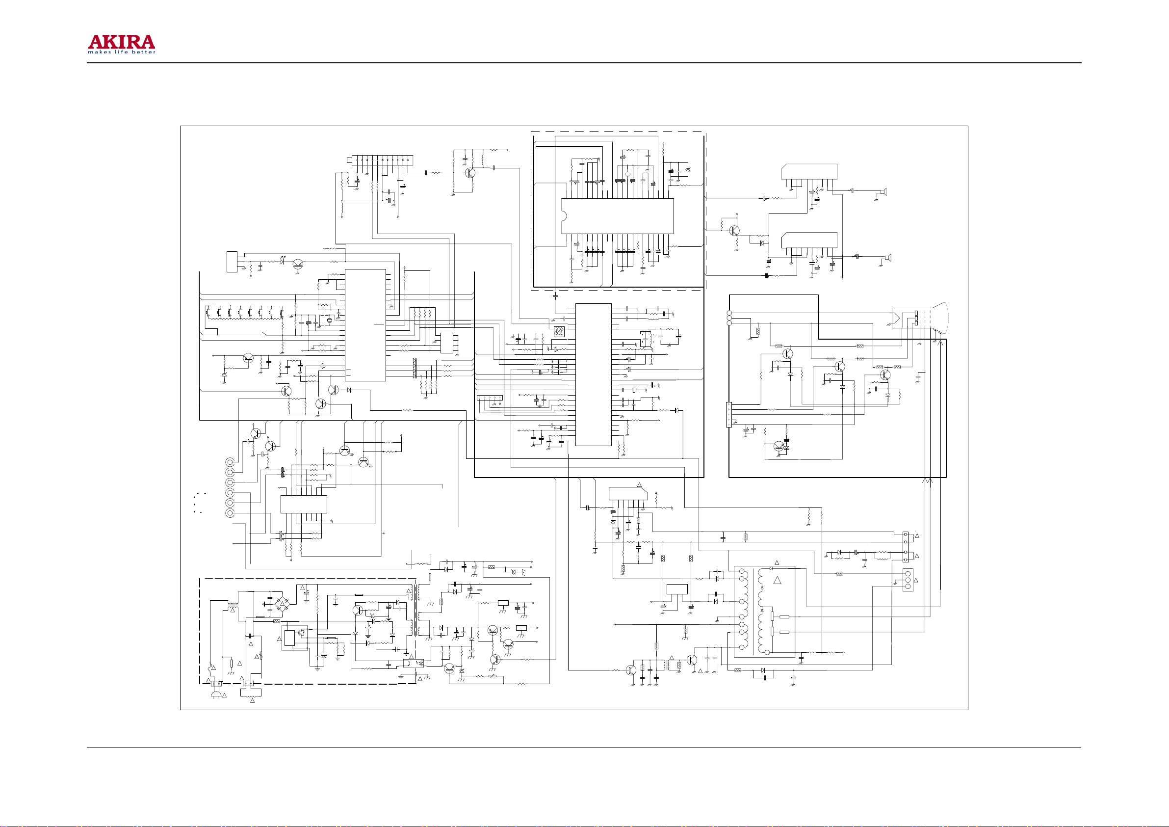
CIRCUIT DIAGRAM
Model No: CT-21LS9MTS
Version 1.0
(OPTION)
FRONT AV
VOL
POWER
PROG-
SW008
RD2
56K
5V(1)
AFT
5V(1)
ZD003
AV V OUT
IC201 PIN40
V OUT
AR OUT
AL OUT
V IN 1
AR IN 1
AL IN 1
!
F601
T3.15A/AC250
!
LN
AC110V
M001
PMA64xxM
PROG+
VOL-
SW007
SW006
RD4
RD3
11K
22K
R032
1.5K
R033
8.2K
3.6V
C435
10U/50V
T601
!
R622
2M7
CN601
!
16
AR IN
9V(2)
C205
100U/16V
C620
Q609
9V(2)
9V(1)
IC004
33V
IC203
L7805
R644
100K/2W
C206
0.01U
R007
100K
R208 47
47U/16V
R211
120
C214
0.01U
R630
10K
C207
5V(2)
C630
0.01U
AR-OUT
AUDIO R
AUDIO L
C016
0.1U
R200 470
R209 470
C237 100P
C240 10U/25V
C222 0.01U
C212
470U/16V
B+
33V
20V
5V(1)
5V(2)
9V(1)
R409
2.2K
C426
R410
0.0082UF
20K
C427
0.015UF
C424 0.015UF
C425 2.2U/50V
42
40
39
41
38
VIR
EOR
LDR
OUTR
OUTL1LDL2VIL3EOL4CAV5Vref6LIL7AVL8SOL9LOL10CTW11CTS12CW13CS14VEO15VEI16CNR17Cm18Cdec19GND20SDA
2.2U/50V
C402
C404
C401
C403 4.7U/50V
0.1U/M
0.0082UF
R402
20K
R401
2.2K
FM
C243
0.047U/M
LA76814
1
A OUT
2
FM OUT
C203
3
PIF AGC
0.022U
4
RF AGC
SAW101
5
IF IN
45B
6
IF IN
7
R008
100K
C219
0.33U
C236 100P
C239 0.22U
R210
3K3
C216
1U/50V
C221
2.2U/50V
R255 100
R254 100
R256 100
C217 0.1U
POWER
0.022U
R201
20K
C215
IF GND
8
IF VCC
9
FM FIL
10
AFT OUT
11
BUS DATA
12
BUS CLOCK
13
ABL
14
R IN
15
G IN
16
B IN
17
FB IN
18
VCC
19
R OUT
20
G OUT
21
B OUT
22
SYNC
23
V OUT
24
RAMP ALC
25
H VCC
26
H AFC FIL
H OUT27FBP IN
V-SYNC
C315
1U/50V
C316
0.033U/M
C423 0.015UF
C406 100U/16V
IC201
R340
5.1K
C419
C450
0.022U
C421 4.7U/50V
C422 2.2U/50V
34
32
36
35
LIR
LOR33SOR
AVR
Cps237Cps1
47U/16V
10U/16V
C450
0.022U
C405
C407
AL IN
AL-OUT
54
SIF IN
53
SIF FIL
52
SIF OUT
51
EXT.A IN
50
APC FIL
49
VCO
48
VCO
47
FLL FIL
46
TV OUT
45
BLACK S.F
44
INT.V IN
43
VCC V/C/D
42
EXT.V IN
41
G V/C/B
40
V OUT
39
ACC FIL
38
XRAL
37
FSC OUT
36
APC1 FIL
35
KILLER FIL
34
XRAY
33
H GND
32
OSD CON
31
NC
30
NC
29
VCO IREF
28
R241
10K
V-IN
R301
7
47K
C325
100/16V
D301
BA158
C304
220U/50V
B+
R307
100
R407
2.2K
X401
2.2U/50V
503F58
C420 4.7U/50V
31
Css
10U/16V
1U/50V
C408
C409
C245
39PF
C241
39PF
C209
0.47U
R225 1K R229 1K
C230
1U/50V
C235
15P
C238
5n6
C228
1000P
R213
1K5
R212
4.7K
IC301
LA7840
R319
15K
R329
10K
R320
1.2 2W
Q301
2SC2482
1U/50V
0.01U
2.7K 1/2W
R114
R110
47
BLK
IC201 PIN42
C640
1000U/25V
C621
0.01U/50V
R653
ZD601
3V9
R109
C321
100U/160V
470U/25V
270
Q101
2SC2717
AFT
OSD-R
OSD-G
OSD-B
BLK
V-IN
C618
R646
3K9
R629
10K
CN201
C642
0.01U
R621
0.82UH
0
L102
R625
15K 2W
Q611
2SA966
VR601
2KB(H)
220
C109
0.01U
5V(2)
5V(1)
9V(2)
ABL
IC601
L7805
10U/50V
R626
0
R628
22
R632
10K
78L09
Q610
2SC1815
NC
SCL
ADD
RFAGC
R103
123456789
120K
C104
4.7U/50V
R107
33K
R101 100
L101
100UH
5V(2)
R002
5V(1)
330U/16V
C001 0.01U
1K
13
ACOM
R435
100
!
C607
Q003
2SA1015
C009
C012
2.2U/50V
R719
AR OUT
12
1
2
5
3
4.7K
OCP/FB
R065
R043
10K
R437
R438
R436
R439
AI311AI0
R431
10K
R434
10K
220U/200V
C614
1000P
C010 0.01U
R037 10K
R036 10K
10
2SC1815
10K
R608
2M2
R022
22K
R021
Q008
10K
10K
10K
R605
2M2
9V(2)
C007
15P
C008
8
15P
CONA9CONB
C014
4.7U/50V
10K
4K7
R001 10K
R013
4.7K
33K
C004
220P
C005
100P
X001
32.768K
Q007
2SC1815
R465
R464
10K
IC401
HEF4052
L602
R610
680
R603
0.22/1W
D605
4148
1
2
3
4
5
6
7
8
9
10
11
12
13
14
15
16
17
18
19
20
21
Q462
2SC1815
C608
0.001U/2KV
R604
0.22/1W
WRITE
IDsecam
IDscart
VOL
COB.F
POWER
TUNE
GND
XTF1
XTF2
VDD
KEY
AFT
PGCin
OPT
RESET
FIL
OPTselect
Vsyn
Hsyn
D201
1N4148
AV/TV SW
Q601
2SC2482
LA8633XX
V-SYNC
Q461
2SC1815
L601
D609
IN4148
IC001
AV1/2 SW
R612 10K
ZD602
15V
D604
IN4148
R643
1K
R613
47/0.5W
100UF/35V
D611
BA158
C610
BALANCE
H-SYNC
AL-OUT
4.7UF/160V
3
CR1
0.022U
2
RD11
1
LED
RR1
1K
1
5V(1)
SLEEP
VOL+
MENU
SEARCH
AV/TV
R067
24K
SW002
SW004
SW005
SW003
SW
C436
R445
10K
C601A
.0047
C601D
.0047
R602
RD7
4.3K
AR-OUT
R601
PTC
10
5V(2)
9V(2)
Q401
2SC1815
9V(2)
0.01U
R038
39K/3W
SW001
RD8
RD9
3K
2K
RD21
16K
5V(1)
C011
0.022U
1M
5V(1)
Q221
2SC1815
R226
2.2K
AL-OUT
R440
100
C432
47U/16V
C431
47U/16V
15
16
VDD
BI01BCOM3BI34BI15INHBIT6VEE7GND
2
C434
47U/16V
C433
47U/16V
R432
10K
1N5397 X4
D601A
D601C
!
D601B
D601D
R607
STR-G6653
4
!
CONTROL
IC602
RD21 15K
CN001 PIN3
R039
100
C013
J147
1K
AR-IN
AI114AI2
BI2
R433
10K
9V(2)
BLOCK
RD5
RD6
6.8K
4.7K
Q006
2SA1015
R034
4.7K
9V(2)
VOUT
Q402
2SC1815
R446
10K
10U/50V
SCK473
C602
.22/250V
!
!
!
!
CN602
L601
DEG.COIL
!
R102 100
S_VHS
M_TRAP
REMOTE
SAFTY
IICCLK
IICDATA
0.1U/63V
SDA
MUTE
DATA
V_L
V_H
UHF
AV2
AV1
SD
CLK
BLK
AL-IN
9V(2)
C623
R609
47
C611
B
G
R
R611
2K2
VCC
C111
0.01U
C110
330U/16V
R463
10K
R462
10K
VCC
42
41
40
39
38
37
36
35
34
33
32
31
30
29
28
27
26
25
24
23
22
D610
BA158
NC
33V
5V(1)
T601
680P/500V
D602
IN4148
C609
0.0033/100V
IC603
IF1
33V
10
5V(1)
R050 9K1
R051 100
R052 100
R240
100K
C605
0.0022U/250V
IF2
TUNER
11
C108
1U/50V
R049 4.7K
D010 1N4148
D009 1N4148
D008 1N4148
D007 1N4148
R4F1
75
1
!
3 7
4
5
6
!
C613
R048 4.7K
R7125K1
0.68/2W
!
C114
R108
0.01U
5.6K
C107
R105
0.01U
0
R111
1K
AV1/2 SW
AV/TV SW
R047 4.7K
R046 4.7K
IC002
24C04
R031
330
OSD-B
R030
330
OSD-G
R029
330
R7115K1
R710
5K1
OSD-R
R7091K
AV VOUT
C615
680P/500V
C616
100U/160V
R618
D607
BYW36
C641
680P/500V
9
D640
BA158
R619
2.2 /2W
10
11
D608
C617
BA158
2200U/25V
12
C619
680P/500V
BA158
R642
C612
1.2K
0.1U
R645
1K
Q602
2SC1815
10U/16V
C439
Cadj29CER30Cmo
R403
1U/50V
R404
C410
150
C411
0.047UF
L203
45.75M
C232
3.579545M
C227
R214
1K
C328
100U/16V
R308
0.0022U/1KV
28
X201
!
9V(2)
C309
C417 0.47U/M
8.2K
10U/16V
R327
2.2 2W
C324
0.47U
C323
1U/50V
R324
3.9K
C233
1122334455667
R318
100K
25V
C322
560P/500V
0.22U/M
Cp126Cp227Cph
C414 10U/16V
R303
5.1K
2200U/25V
C418
C416
25
C413 0.1U/C
R243
1K
L241
15UH
R221
10K
9V(2)
C326
220U/16V
100U/16V
24
Vcap
C412 4.7U/50V
C242
0.001U
C231
0.1U
C320
0.056U/250V
9V(2)
COMP
C246
0.01U
R222
22K
5V(2)
R330
1.5K
R306
5.1K 5W
C310
23
R408
12/1W
220U/16V
C441
100P
Vcc
R233
C224
0.001U
R309
1K 1W
T301
C415
22
SCL
21
R405
100
C440
100P
390
5V(2)
123
!
C442
0.01U
IC404TDA9852
D221 IN4148
180 1W
IC302
LA7809
C301
47U/50V
150K 1/2W
R310
22 1/2W
R406
100
C247
0.47U/50V
AV V IN
AV V OUT
R311
R620
ZD401
8V2
SCL
SDA
R316
3.9/2W
C313
.0047/2KV
2SD2499
Q302
!
AUDIO L
VOL
CPU PIN5
AUDIO R
CN301B
FROM CN301
CN201B
FROM CN201
C327
0.1U
C317
680P/500V
D304
BA158
C318
680P/500V
D310
BA158
C314
.0076/2KV
IC402
LA4285
INT1GND2EXT3SW4VOL566NF7GND8OUT9VCC
Q503
D505
1N4148
C506
470u/16V
D504
2SC2482
C448
100U/25V
C445
100U/25V
IC403
LA4285
R508
2K2
R441
R442
R237
560K
R412
4.7K
C437
10UF/50V
9V(2)
R468
15K
Q464
2SC1815
R466
4.7K
D401
R467
W1 W2 W3
1 BO
2 GO
3 RO
4 GND
5 +9V(2)
1.8K
3 HEATER
2 GND
1 +180V
10u/25V
4
1
10U/50V
C438
10UF/50V
C507
C505
0.01U
R326
270 2W
T603 FBT
4148
C453
R523
R530
150K/1W
R503
150
10K
R413
4.7K
15K/2W
R502
150
Q508
2SC1815
INT1GND2EXT3SW4VOL566NF7GND8OUT9VCC
R514
R506
390
C503
150P
R524
270
BA158
!
!
1K
1U/50V
100
1U/50V
C446
C451
R235
5K1
C452
1000UF/25V
R513
15K/2W
R505
390
R501
150
10
10
20V
C502
150P
D306
BA157
R315
22K 1W
R317
0.68 2W
C444
220/25V
C447
220/25V
R511
2K7 1/2W
R510
2K7 1/2W
Q502
2SC2482
D506
R507
1N4148
2K2
CRT PCB
C312
1U/250V
C311
0.47U 250V
15K/2W
R515
390
SPEAKER
8R 3W
SPEAKER
8R 3W
CRT
V501
EHT
R512
R509
2K7 1/2W
Q501
2SC2482
C504
1000P/2KV
C501
150P
D507
R504
1N4148
2K2
CN302
!
R331
44UH
1K5/1W
L301
CN301
3
2
1
!
!
2
FOCUS
SCREEN
R322
0.68 2W
7
3
8
R207
10
6
D305
BA158
C302
C303
10U/250V
680P/500V
C308
0.056U/M
R236
1K
680
5V(2)
Page 17

 Loading...