

Page 1
Short Form Service Manual
Item 9 on page 9 / Pos. 9 auf Seite 9
WMS 400
*
April 14, 2005
Last Modification / letze Änderung:
Page 3: PS01/4000 deleted / Seite 3: PS01/4000 gestrichen
Page 6: dismantling instructions added / Seite 6 Zerlegeanleitung hinzu
Former Modifications / frühere Änderungen:
Color code identification PT 400, HT 400 / Farbcode-Kennzeichnung PT 400, HT 400
Page 11: item 7,9,10
Page 3: Packaging elements added
Page 6: Subitems of 5 deleted / Untervarianten von 5 gestrichen
Part number for PT400 Antenna
Pages 13+14:Item 1.6 added / Seiten 13+14:Pos 1.6 hinzu
New frequency set IIIK added / neues Frequenz-Set IIIK hinzu
___________________________________________________________________________
AKG Acoustics GmbH, A Harman International Company, Lemböckgasse 21-25, A-1230 Wien, Austria
Phone: (+431) 86654-1519, Fax: (+431) 86654-1514, e-mail: service@akg.com
Page / Seite 1 of / von 14
Page 2

WMS 400 Service Manual General Information
Table of contents:
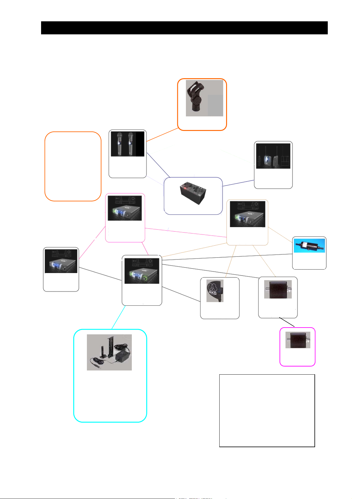
The complete WMS 400 family 3 Die komplette WMS 400 Familie
HT 400 Handheld Transmitter 4 HT 400 Handsender
PT 400 Pocket Transmitter 8 PT 400 Taschensender
SR 400 Receiver 10 SR 400 Empfänger
RMU Rack mount elements 12 RMU Rack - Montageelemente
RMS 4000 Remote mute switch 12 RMS 4000 Remote-Fernschalter
CU 400 Charging unit 13 CU 400 Ladegerät
Page / Seite 2 of / von 14
Page 3
WMS 400 Service Manual General Information
R
WMS 400-Set
Packaging/Verpackung:
Case/Koffer:
3831P0001
Inlay/Einlage:
8998P0120
Inlay (lid) /
Einlage (Deckel):
8998P0121
Inlay (bottom) /
Einlage (Boden):
8998P0123
HUB 4000
7620H09..
2999Z00..
The complete WMS 400 - Family
Stand adapter SA63
6001H6301
HT 400
2931Z00..
2931Z90..
CU 400
PT 400
2932Z00..
PSU 4000
7620H07..
2997Z00..
HPA 4000
7620H08..
2998Z00..
SR 400
2930Z00..
2930Z90..
RMU see SR4000
Power adapter:
Europe 0027E0047
UK 0027E0049
USA 0027E0048
Japan 0027E0059
AUS 0027E00..
Those components belonging to the WMS 4000 system are contained in
the WMS 4000 manual only.
Geräte aus dem WMS 4000 Programm sind nur im WMS 4000 Service
Manual enthalten.
and PS4000
parts list
PS 4000
7620H06..
2996Z00..
SRA 2B
3009Z0001
S
HT Handheld Transmitter
PT Pocket Transmitter
PS Power Splitter
SRA Stationary receiver antenna
RA Receiver antenna
AB Antenna booster
ASU Antenna supply unit
PSU Power supply unit
HPA Headphone amplifier
RMU Rack-mount unit
BP Battery pack
CU Charging unit
Stationary receiver
AB 4000
3009Z0002
3009Z0003
RA 4000 B
2632Z0030
ASU 4000
3009Z0004…
3009Z0011
Page / Seite 3 of / von 14
Page 4
WMS 400 Service Manual HT 400
4
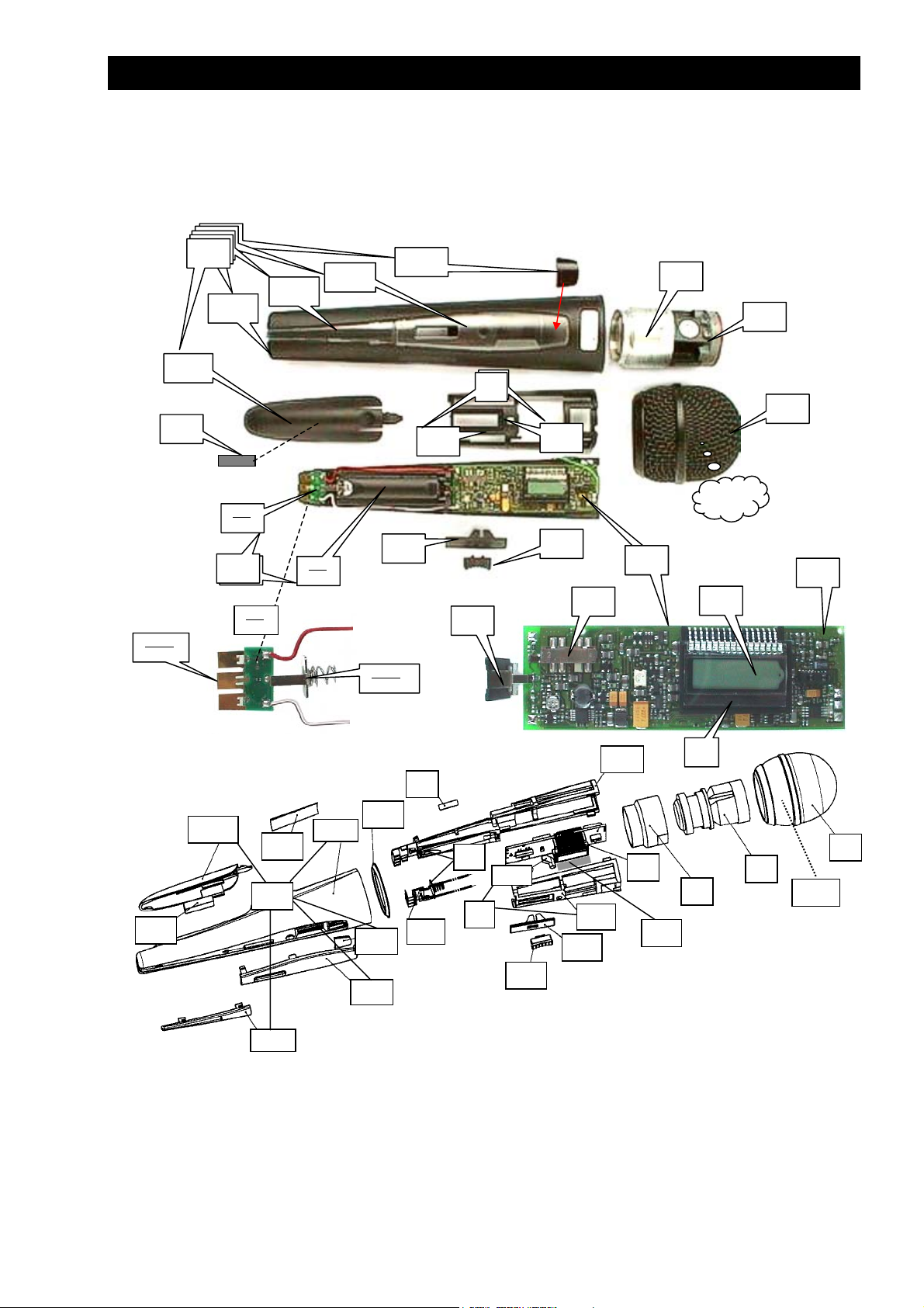
HT 400 (2931Z00..)
19
3
2
4
4
1
4.2
1.1
16
6
6
6.1
10
5.2
5.2.1
12.2
11
12
12
12
12
12
12.1
5.2
5
5
5.2
12.4
12.5
12.3
4.1
15
5.1
red/rot
5.2.2
11
12.2
12
12.3
20
12.1
white/weiß
22
12.5
12.4
9
5.2
23
8
1
2
3
1.1
5.1
5
4.1
15
16
6
Page / Seite 4 of / von 14
Page 5
WMS 400 Service Manual HT 400
Page / Seite 5 of / von 14
Page 6

WMS 400 Service Manual HT 400
HT 400 Parts list HT 400 Stückliste
HT400/D880 … A HT400/C900 … B
Description Item
Pos.
Wire-mesh cap 1 9999N0718 1 - Gitterkappe
Wire-mesh cap 1 9999N0719 - 1 Gitterkappe
Foam insert 1.1 7030016 1 1 Schaumeinlage
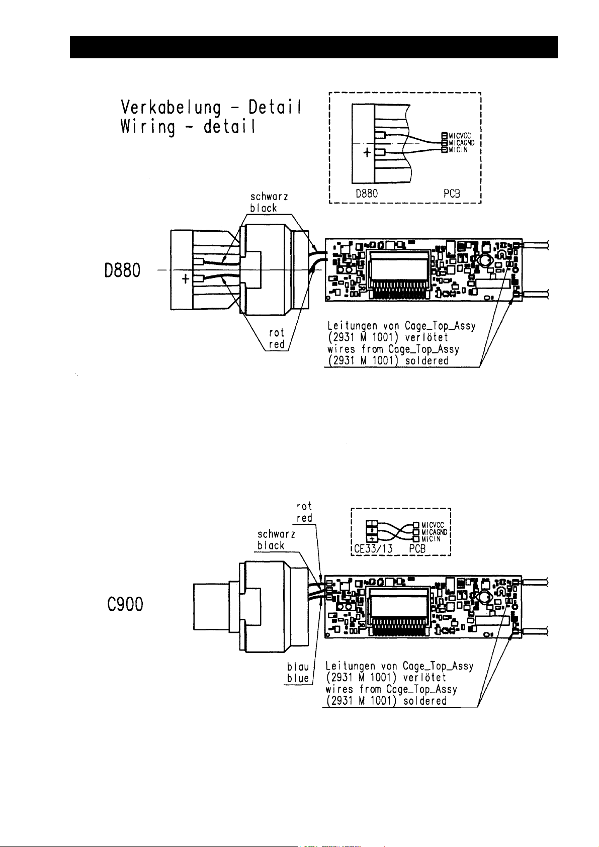
Dynamic capsule D880 2 2610Z0030 1 - Dynamische Kapsel D880
Electret capsule C900 2 2931M0501 - 1 Elektretkapsel C900
Capsule bearing 3 2931Z2201 1 1+) Kapsellager
Cage bottom assembly 4 2931M0801 1 1 Käfig Unterteil, komplett
Cage bottom 4.1 2931Z1201 1 1 Käfig Unterteil
Light guide 4.2 2931Z2101 1 1 Lichtleiter
Cage top assembly 5 2931M1001 1 1 Käfig Oberteil, komplett
Cage top 5.1 2931Z1101 1 1 Käfig Oberteil
Charging board, complete 5.2 2931M0201 1 1 Ladeprint, komplett
Charging contact 5.2.1 2931Z3001 3 3 Ladekontakt
Battery contact "-" 5.2.2 2931Z1901 1 1 Batteriekontakt "-"
Printed circuit board, complete 6 2931M.... *) 1 1 Print, komplett
Slide switch 6.1 9040E0010 1 1 Schiebeschalter
Display holder 8 2931Z2901 1 1 Displayhalter
Sticker 9 4717S0001 1 1 Schild
Display 10 2931Z3501 1 1 Display
Foam pad 11 2932Z2101 1 1 Schaumstoffstreifen
Housing, complete
with colour code plate 'black'
Housing 12.1 2931Z1001 1 1 Gehäuse
Battery cover 12.2 2931Z1301 1 1 Batteriedeckel
Identification plate, black 12.3 2931Z1502 1 1 Indikatorplatte, schwarz
Identification plate, transparent 12.3 2931Z1501 *** *** Indikatorplatte, transparent
Display cover 12.4 2931Z1401 1 1 Display – Abdeckung
IR - window 12.5 2931Z1601 1 1 IR - Fenster
Slider 15 2931Z1701 1 1 Schieber
Switch knob 16 2931Z1801 1 1 Schalterknopf
Battery contact "+" 19 2931M0401 1 1 Batteriekontakt "+"
Device sticker 20 4764S00.. **) 1 1 Typenschild
Ring, gilded 22 2931Z3701 - 1 Goldring
Foam pad 23 2931Z2801 1 1 Schaumstoffstreifen
Microphone clip SA63 -- 6001H6301++) 1 1 Stativklammer SA63
Name-plate sheet, white -- 2931Z3601 1 1
+) contained in 2931M0501 / in 2931M0501 enthalten ++) Sales item / Vertriebsware
*) For part number see following tables / Teilenummern können nachstehenden Tabellen entnommen werden
**) last two digits equal to the 2931Z00.. variation number of table below
**)Letzte 2 Stellen gleich der 2931Z00.. Variantennummer laut untenstehender Tabelle
*** included only in WMS 400 HT-Set / nur im WMS 400 HT-Set beigepackt
To dismantle the HT 400 please proceed as follows:
Turn off the top grille and unsolder the capsule leads.
Then turn out the capsule with it's threaded holder
ring. Now remove the switch knob '16' (2931Z1801).
This will not be possible without breaking it. Further
remove slider '15' (2931Z1701). Also this part will
break and needs to be replaced. Now take the
electronics of from the housing. When reassembling it
may be useful to solder extension leads to the wires to
the capsule. After attaching the threaded ring with
capsule these wires can be removed again.
12 2931M0701 1 1 Gehäuse, komplett mit
Part number
Bestellnummer
Zum Zerlegen des HT 400 gehen Sie bitte wie folgt vor:
Schrauben Sie die Kappe ab und entlöten Sie die
Kapselanschlüsse. Jetzt können Sie die Kapsel mit dem
Gewindering herausdrehen. Anschließend sind die Teile 16
(2931Z1801) und 15 (2931Z1701) zu entfernen. Diese
werden dabei brechen und müssen ersetzt werden. Nun
kann die Senderelektronik aus dem Gehäuserohr gezogen
werden. Beim Zusammenbau kann es hilfreich sein, die
Kapseldrähte mit Litzen zu verlängern. Diese können nach
festschrauben der Kapsel wieder entfernt werden.
Quantity
Stück
A B
Bezeichnung
Farbcodeplatte 'schwarz'
Blatt mit Einlageschildern, weiß
Page / Seite 6 of / von 14
Page 7

WMS 400 Service Manual HT 400
2931
1151 x
1251 x
1311 x
1312 x
1551 x
1522 x
1513 x
1611 x
2931
1151 x
1251 x
1311 x
1312 x
1551 x
1522 x
1513 x
1611 x
01 02 03 04 05 06 07 08 09 10 11 12 13 14 15 16 17 18 19 20
II
M.... I 50
21 22 23 24 25 26 27 28 29 30 31 32 33 34 35 36 37 38 39 40
M.... I 50
V-A
50
II
V-A
50
50
50
V-C
20
V-C
20
V-J
10
V-J
10
HT 400 / D 880 2931Z00..
HT 400 / C 900 2931Z00..
III
10
III
10
III
K10
III
K10
VI-
A10
VI-
A10
Page / Seite 7 of / von 14
Page 8

WMS 400 Service Manual PT 400
1
4
PT 400 (2932Z00..)
8
5
2.1.1
2.1.7
2.1.6
8
1.1
13
2.2
2.4
12
1
1.2
9
2.1.5
11
2.1.4
2.1.3
14
2.1.2
12
4
2.3
13.1
Item 2 = Housing, complete
Item 2.1 = Housing top, wired
Item 2.1.1 = Housing top, empty
Pos 2 = Gehäuse, komplett
Pos 2.1 = Gehäuseoberteil, verdrahtet
Pos 2.1.1 = Gehäuseoberteil, leer
2.1.6
8
1.1
13
12
14
2.1.1
9
5
2.3
1.2
2.1.7
17
7
15
6
2.1.3
2.1.5
2.1.2
2.1.4
10
11
2.4
2.2
Page / Seite 8 of / von 14
Page 9

WMS 400 Service Manual PT 400
L
PT 400 Parts list PT 400 Stückliste
Description Item
Pos.
Printed circuit board, complete 1 2932M.... *) 1 Print, komplett
Slide switch 1.1 0040E0212 1 Schiebeschalter
Jack socket 3pole 2,5mm 'Mute' 1.2 0017E0356 1 Klinkenbuchse 3polig 2,5mm
Housing, complete 2 2932M0501 1 Gehäuse, komplett
Housing, complete 2 2932M0601 1 Gehäuse, komplett
Housing top, wired 2.1 2932M0401 1 Gehäuse Oberteil, verdrahtet
Housing top 2.1.1 2932Z1201 1 Gehäuse Oberteil
Charging contact 2.1.2 2932Z2001 3 Ladekontakt
Battery contact "+" 2.1.3 2932M0201 1 Batteriekontakt "+"
Battery contact "-" 2.1.4 t.b.a. 1 Batteriekontakt "-"
NTC resistor 2.1.5 0004E5000 1 NTC – Widerstand
Mini-XLR - socket 3pole 2.1.6 0016E0371 1 Mini-XLR – Buchse 3polig
Nut for 2.1.6 2.1.7 3002Z1501 1 Mutter für 2.1.6
Housing bottom 2.2 2932Z1101 1 Gehäuse Unterteil
Battery cover 2.3 2932Z1301 1 Batteriedeckel
Belt clip 2.4 2932Z1601 1 Gürtelspange
Window 4 2932Z1401 1 Fenster
Display cover 5 2932Z1501 1 Display - Abdeckung
Display 6 2932Z2701 1 Display
Light guide 7 2932Z1701 1 Lichtleiter
Slide button 8 2932Z1801 1 Schiebeknopf
Volume control button, former version 9 2932Z1901 1 Lautstärkereglerknopf, alt
Volume control button, current version 9 2932Z1902 1
Sticker 10 4717S0001 1 Schild
Foam pad 11 2932Z2101 1 Schaumstoffstreifen
Screw PT KB 18x8 12 0099N1802 2 Schraube PT KB 18x8
Security screw PT18x8 12 9999N0701 2 Sicherheitsschraube PT18x8
Antenna 13 2932M030. **) 1 Antenne
Antenna cap 13.1 2890Z1801 1 Kappe
Device sticker 14 4762S00.. *) 1 Typenschild
Display holder 15 2932Z2401 1 Displayhalter
Protective tape 16 2932Z2301 1 Schutzfolie
Shielding plate 17 2932Z2601 1 Schirmplättchen
Mute plug -- 3002Z2901 2 Mute – Stecker
Cable MK/GL -- 0110E0218 1 Kabel MK/GL
Name-plate sheet, white -- 2932Z2801 or/oder
*) Frequency-depending, please state frequency when ordering / Frequenzabhängig, bitte Frequenz angeben
**) Last digit of part number is equal to number of frequency band (e.g. 2932M0305 for V-A, V-C and V-J)
**) Letzte Stelle der Teilenummer ist gleich der Nummer des Frequenzbandes (z.B.: 2932M0305 für V-A, V-C und V-J)
2932Z
90..
*
01 02 07 08 09 11 12 14
I
II
**
50
V-A
50
50
V-C
20
1151 1 x
1251 2 x
1311 11 x
1312 12 x
1551 7 x
1522 8 x
1513 9 x
1611 14 x
L/mm
101 97 80 80 80 90 90 76
*) Last 4 digit of part number for items 1 and 13 according to frequency band / power in mW
*) Letzte 4Stellen der Bestellnummer für Pos. 1 und 13 gemäß Frequenzband / Leistung in mW
**) Last two digits of part number for item 14 according to frequency band / power in mW
**) Letzte Stellen der Bestellnummer für Pos. 14 gemäß Frequenzband / Leistung in mW
Antenna 2932M0301
13.1
Part number
Bestellnummer
2932Z2901
V-J
10
III
10
III
VI-A
K10
Quantity
Bezeichnung
Stück
Lautstärkereglerknopf, aktuell
1 Blatt mit Einlageschildern, weiß
10
13
Page / Seite 9 of / von 14
Page 10

WMS 400 Service Manual SR 400
SR 400 (2930Z00..)
18
15
17
2.2
2.1
2.3
2.6
2.4
2
14
5
2.5
23
6
2.1
2.2
24
2.3
15
2
4
3
7
15
15
18
13
19
12
11
16
25
2.6
2.5
24
14
2.4
24
3
4
5
7
6
7
7
Page / Seite 10 of / von 14
Page 11

WMS 400 Service Manual SR 400
SR 400 Parts list SR 400 Stückliste
Description Pos. Part number
Bestellnummer
Printed circuit board, complete 2 2930M…. *) 1 Print, komplett
XLR-socket 2.1 0016E0369 1 XLR – Buchse
BNC-socket 2.2 0017E0242 2 BNC – Buchse
Stereo jack socket 2.3 0017E0357 1 Stereo - Klinkenbuchse
Potentiometer 'Volume' 2.4 0021E0070 1 Potentiometer 'Pegel'
ON/OFF switch 2.5 0040E0213 1 ON/OFF Schalter
Slide switch 2.6 0040E0208 1 Schiebeschalter
Volume button 3 2930Z1401 1 Knopf für Lautstärkeregler
ON/OFF button 4 2930Z1501 1 ON/OFF – Knopf
Front board, complete 5 2930M0101 1 Front - Print, komplett
5 2930M0102 1#
Push button switch 5.1 0040E0197 3 Druckschalter
Display with backlight 5.2 0050E0003 1 Display mit Beleuchtung
Ribbon cable, 15-pole 5.3 0110E0273 1 Flachbandkabel, 15-polig
IR-Transceiver 5.4 9050E0004 1 IR-Sende-Empfangseinheit
Button group 6 2930Z1201 1 Knopf – Gruppe
Front panel, complete 7 2930M0701 1 Frontplatte, komplett
Front panel 7 2930Z1001 1 Frontplatte
Display cover 8 2930Z1101**) 1 Display – Abdeckung
IR - window 9 2930Z1601**) 1 IR – Fenster
Color indicator window 10 2930Z1301 1 Farbcode – Fenster
Insulating washer 11 2930Z1801 1 Isolierscheibe
Insulating disk 12 2930Z1901 1 Isolierscheibe
Spacer 13 3000Z2101 4 Hülse
Bracket 14 2998Z1601 2 Klammer
Screw M3x8 15 7985D3011 7 Schraube M3x8
Housing foot 16 3000Z2001 4 Gehäusefuß
Cable, mounted 17 0110E0271 1 Kabel, montiert
Cover 18 3000Z1603 1 Deckel
Hexagonal nut 19 2930Z2101 1 Sechskantmutter
Sticker 21 4717S0001 1 Schild
Device sticker 22 4761S00.. *) 1 Typenschild
Antenna 23 0018E0224 2 Antenne
Screw PT KB 30x8 24 0099N3008 6 Schraube PT KB 30x8
Screw 3x12 25 7985D3012 4 Schraube 3x12
Power adapter EU 12V/500mA -- 0027E0047 + Netzadapter EU 12V/500mA
Power adapter US 12V/500mA -- 0027E0048 + Netzadapter US 12V/500mA
Power adapter UK 12V/500mA -- 0027E0049 + Netzadapter UK 12V/500mA
Power adapter Jap 12V/500mA -- 0027E0059 + Netzadapter UK 12V/500mA
Rack mount unit RMU 1 -- 3000Z2501 1 Rack-Montageteil RMU 1
Rack mount unit RMU 2 -- 3000Z2601 1 Rack-Montageteil RMU 2
Rack mount unit RMU 4 -- 3000Z2701 1 Rack-Montageteil RMU 3
Filler piece for housing slots -- 3000Z1801 4 Einsatz für Gehäuseschlitze
*) Frequency-depending, please see table below for part numbers
*) Frequenzabhängig, bitte Bestellnummern unten stehender Tabelle entnehmen
**) Please order both parts, they have to be changed together/ Bitte beide Teile bestellen, sie müssen gemeinsam getauscht werden
+) depending on variation / Variantenabhängig #) For Japan – version only / Nur für Japanvariante
Frequency band and power / Frequenzband und Leistung
I
Pos
2930Z90.. 01 02 03 04 05 06 07 08
2930M 1151 1251 1311 1312 1551 1522 1611 1513
2
4761S 0001 0002 0003 0004 0005 0006 0007 0008
22
II III III-K V-A V-C VI-A V-J
Quantity
Bezeichnung
Stück
Page / Seite 11 of / von 14
Page 12

WMS 400 Service Manual RMU, RMS 4000
'RMU' Rack mount elements / 'RMU' Rack-Montageelemente
SR400 Description
RMU1 3000Z2501 1
RMU2 3000Z2601 1
RMU4 3000Z2701 1 short front, short side / kurze Frontseite, kurzer Seitenschenkel
Cover
Abdeckung 9999N0581 2
RMS 4000 REMOTE MUTE SWITCH / MUTE-FERNSCHALTER
long front as necessary for one item in a 19" rack, short side / lange
Frontseite, kurzer Seitenschenkel, wird für ein Gerät in 19" Rack benötigt
coupling piece for two items, to be inserted instead of housing feet /
Koppelstück für zwei Geräte. Wird statt der Gehäusefüsse montiert
for antenna socket holes of RMU1 and RMU4
für Antennenöffnungen in RMU1 und RMU4
Clip 3009Z3201
Page / Seite 12 of / von 14
Page 13

WMS 400 Service Manual CU 400
1
1.5
1.1
1.6
1.4
1.3
1.2
2.1
2.3
2.6
2.7
2.4
2.2
2
Page / Seite 13 of / von 14
Page 14

WMS 400 Service Manual CU 400
CU 400 Parts list 2934Z00.. CU 400 Stückliste
Description Pos. Part number
Bestellnummer
Printed circuit board, complete 1 2934M0101 1 Print, komplett
Metal plate 1.1 2934Z1201 1 Metallplatte
Screw M3x8 1.2 7500D3000 1 Schraube M3x8
Light guide 1.4 2934Z1601 2 Lichtleiter
Transistor clip 1.5 0013E0201 2 Transistorklammer
DC - socket 1.6 0018E0221 1 DC - Buchse
Housing, top assembly 2 2934M1101 1 Gehäuse - Oberteil
Housing top 2.1 2934Z1001 1 Gehäuse - Oberteil
Contact pin 2.2 2934Z1401 12 Kotaktstift
Spring 2.3 9999N0689 12 Feder
Contact part 2.4 2934Z1301 2 Kontaktteil
Screw 30x10 2.6 0099N3002 2 Schraube 30x10
Cable assembly 2.7 2934M1002 2 Kabelsatz
Housing, bottom 3 2934Z1102 1 Gehäuse – Unterteil
Foot 4 9999N0693 4 Fuß
Screw 30x10 5 0099N3002 2 Schraube 30x10
Sticker 6 9110U3365 1 Schild
Sticker 7 3000Z3701 1 Schild
Rechargeable battery -- 0026E0025 2 Akku
Power adapters / Netzteile
CU 400 AC/DC Adapter
EU
US
UK
Neutral
2934Z0001 0027E0054
2934Z0002 0027E0055
2934Z0003 0027E0056
2934Z0004 none
Quantity
Stück
Bezeichnung
Page / Seite 14 of / von 14
 Loading...