

Page 1

WMS
400/450/470
Service Manual
11/11
AKG Service Department
Lemböckgasse 21-25
A-1230 Wien, Austria
Phone: (+431) 86654-0
Fax: (+431) 8 6654-1514
e-mail: service@akg.com
1/19
Page 2

WMS 400/450/470 General Information
Table of conten ts :
The complete WMS 400 family 3 Die komplette WMS 400 Familie
HT 4xx Handheld Transmitter 4 HT 4xx Handsender
PT 4xx Pocket Transmitter 10 PT 4xx Taschensender
SR 4xx Receiver 13 SR 4xx Empfänger
Power supplies 16 Netzteile
RMU Rack mount elements 16 RMU Rack - Montageelemente
RMS 4000 Remote mute switch 16 RMS 4000 Remote-Fernschalter
CU 400 Charging unit 17 CU 400 Ladegerät
Front antennas 19 Front-Antennen
Last modification:
add WMS470 parts
Page 14 power supplies added
crossed out page 13 pos.1
add new frequency band VII and VIII
new partnumbers on page 6 pos.12, page 10 pos.2, page 13 pos.7
new and corrected partnumbers on page 13
2/19
Page 3
WMS 400/450/470 General Information
HT400/450/470
PT400/450/470
PSU4000
PS4000
CU400
RA4000B
RA2B
ASU4000
AB4000
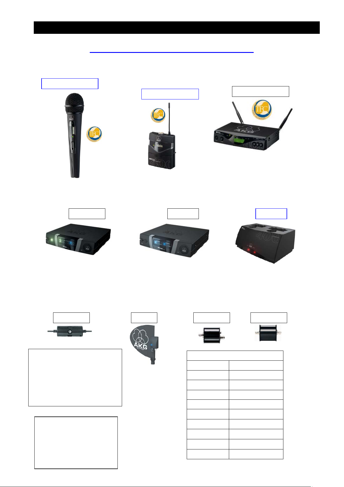
The complete WMS 400/450/470 - Family
PSU4000, PS4000, RA4000B,
RA2B, ASU40 00, AB 4 0 00.
Those components belonging to the
WMS 4000 system are contained in
the WMS 4000 manual only.
Geräte aus dem WMS 4000
Programm sind nur im WMS 4000
Service Manual enthalten.
SR Stationary receiver
HT Handheld Transmitter
PT Pocket Transmitter
PS Power Splitter
RA Receiver antenna
AB Antenna booster
ASU Antenna supply unit
PSU Power supply unit
CU Charging unit
Frequency range Mhz
Band I 650 - 680
Band II 680 - 710
Band III 720 - 750
Band IV 760 - 790
Band V 790 - 829
Band VI 835 - 865
Band VII 500 - 530
Band VIII 570 – 600
Band IX 600 – 630
Band X 823 - 832
3/19
Page 4
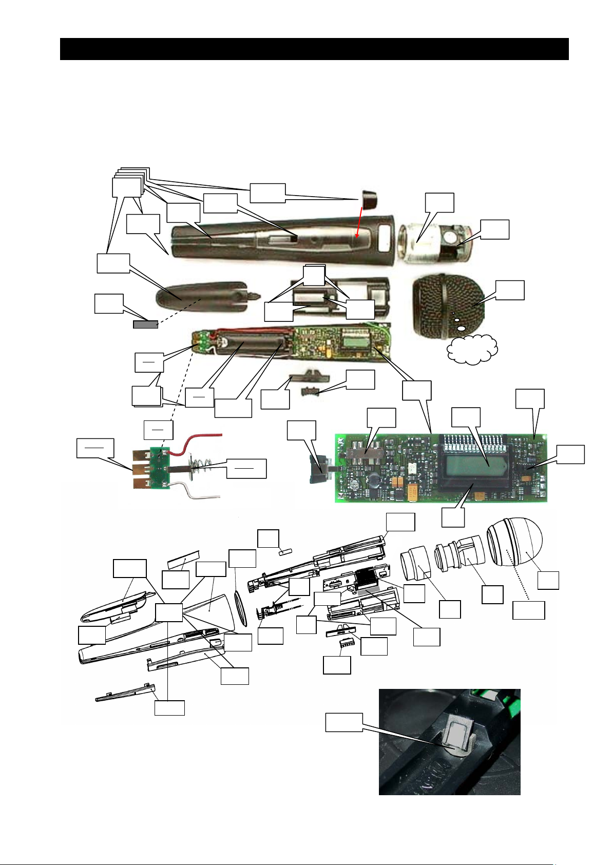
WMS 400/450/470 HT400/450/470
HT 400 (2931Z00..)
HT 450 (3231Z90..)
HT 470 (3301Z90..)
19
3
2
4
4
1
4.2
1.1
16
6
6
6.1
10
5.2
5.2.1
12.2
11
12
12
12
12
12
12.1
5.2
5
5
5.2
12.3
5.1
12.4
12.5
4.1
15
5.2.3
red/rot
5.2.2
6.2
11
12.2
12
12.3
20
12.1
white/weiß
22
12.5
12.4
9
5.2
23
8
1
2
3
1.1
5.1
5
4
16
5.2.3
4.1
15
6
4/19
Page 5
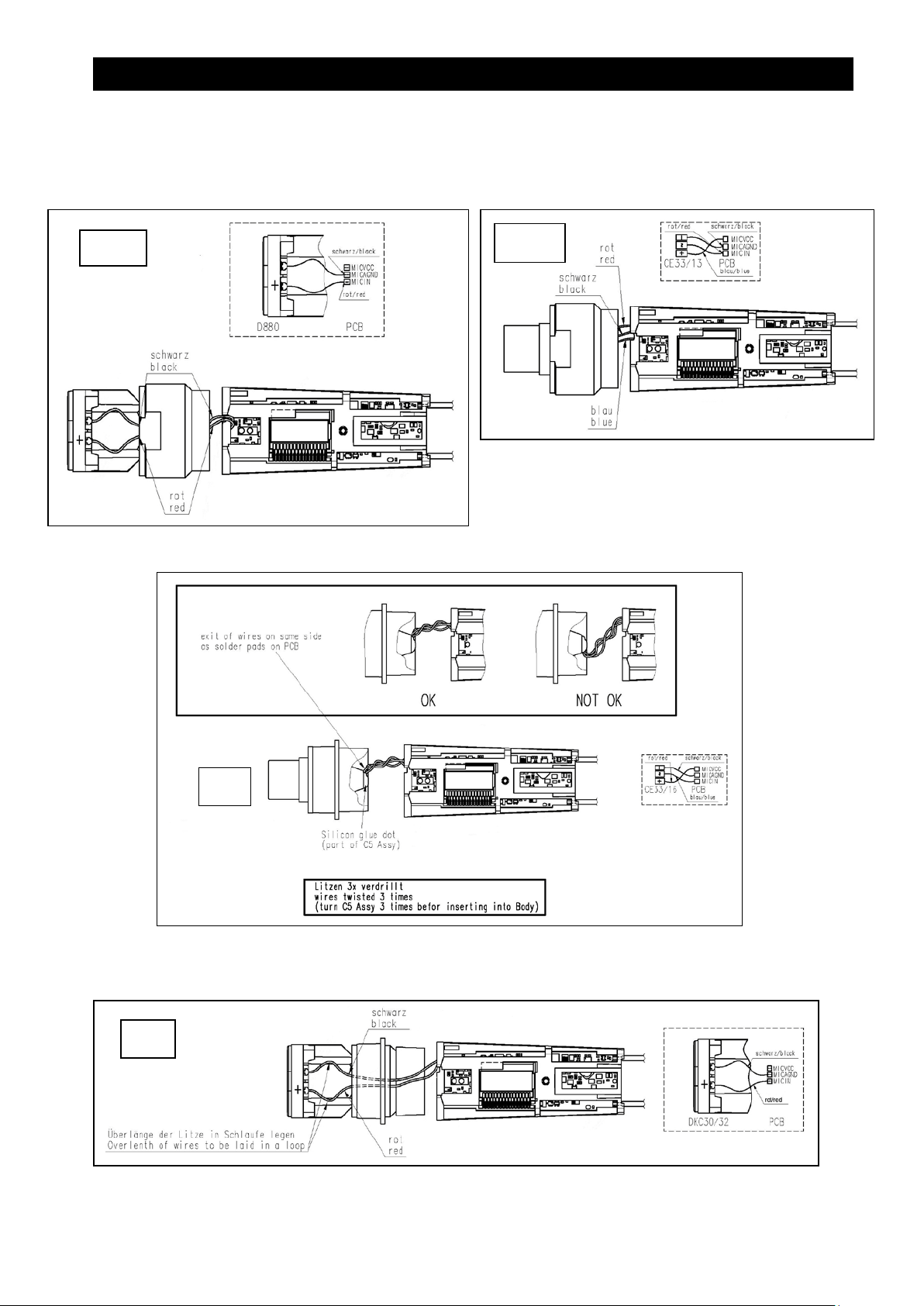
WMS 400/450/470 HT400/450/470
D880
HT400/450/470 Verkabelung / Wiring
C900
D5
C5
5/19
Page 6

WMS 400/450/470 HT400/450/470
Wire-mesh cap
1
3138M11030
- - - 1 - 1 Gitterkappe
Electret capsule C5
2
3231M02010
- - 1 - 1 - Elektretkapsel C5
Charging board, compl.
5.2
2931M02010
1 1 1 1 1 1 Ladeprint, komplett
complete
HT 400/450/470 Parts list HT 400/450/470 Stückliste
HT400/D880…A HT400/C900…B HT450/C5...C HT450/D5...D HT470/C5…E HT470/D5… F
Description
Wire-mesh cap 1 9999N07180 1 - - - - - Gitterkappe
Wire-mesh cap 1 9999N07190 - 1 - - - Gitterkappe
Wire-mesh cap 1 3138M11040 - - 1 - 1 - Gitterkappe
Foam insert 1.1 70300160 1 - - - - - Schaumeinlage
Foam insert 1.1 70302090 - 1 - - - - Schaumeinlage
Foam insert 1.1 3138Z25020 - - 1 - 1 - Schaumeinlage
Foam insert 1.1 3138Z25010 - - - 1 - 1 Schaumeinlage
Dynamic capsule D880 2 2610Z00300 1 - - - - - Dynamische Kapsel D880
Electret capsule C900 2 2931M05010 - 1 - - - - Elektretkapsel C900
Dynamic capsule D5 2 2610Z00320 - - - 1 - 1 Dynamische Kapsel D5
Capsule bearing 3 2931Z22010 1 1+ - - - - Kapsellager
Adapter C5 D5 3.1 3231Z10010 - - 1 1 1 1 Adapter C5 D5
Cage bottom assembly 4 2931M08010 1 1 1 1 1 1 Käfig Unterteil, komplett
Cage bottom 4.1 2931Z12020 1 1 1 1 1 1 Käfig Unterteil
Light guide 4.2 2932Z17010 1 1 1 1 1 1 Lichtleiter
Cage top assembly 5 2931M10010 1 1 1 1 1 1 Käfig Oberteil, komple tt
Cage top 5.1 2931Z11010 1 1 1 1 1 1 Käfig Oberteil
Item
Pos.
Part number
Bestellnummer
A B C D E F
Quantity
Stück
Bezeichnung
Charging contact 5.2.1 2931Z30010 3 3 3 3 3 3 Ladekontakt
Battery contact "-" 5.2.2 2931Z19010 1 1 1 1 1 1 Batteriekontakt "-"
Battery contact
damping
Printed circuit board,
complete
Printed circuit board,
Slide switch 6.1 9040E00100 1 1 1 1 1 1 Schiebeschalter
IR-Transceiver 6.2 9050E00040 1 1 1 1 1 1 IR-Sende-Empfänger
Display holder 8 2931Z29010 1 1 1 1 1 1 Displayhalter
Sticker 9 4717S00010 1 1 1 1 1 1 Schild
Display 10 2931Z35010 1 1 1 1 1 1 Display
Foam pad 11 2931Z39010 1 1 1 1 1 1 Schaumstoffstreifen
Housing, complete 12 2931M07010 1 1 - - - - Gehäuse, komplett mit
Housing, complete 12 3231M07010 - - 1 1 - - Gehäuse, komplett mit
Housing, complete 12 3231M07020 - - - - 1 1 Gehäuse, komplett
Housing 12.1 2931Z10010 1 1 - - - - Gehäuse
Housing 12.1 2931Z10040 - - 1 1 - - Gehäuse
Housing 12.1 2931Z10070 - - - - 1 1 Gehäuse
Battery cover 12.2 2931Z13010 1 1 - - - - Batteriedeckel
Battery cover 12.2 2931Z13020 - - 1 1 1 1 Batteriedeckel
Identification plate,
black
Identification plate,
black
Identification plate,
transparent
Display cover 12.4 2931Z14010 1 1 1 1 1 1 Display – Abdeckung
IRDA - window 12.5 2931Z16010 1 1 1 1 1 1 IRDA - Fenster
Slider 15 2931Z17010 1 1 1 1 1 1 Schieber
Switch knob 16 2931Z18010 1 1 1 1 1 1 Schalterknopf
Battery contact "+" 19 2931M04010 1 1 1 1 1 1 Batteriekontakt " +"
Device sticker, HT400 20 4764S00.. **) 1 1 - - - - Typenschild, HT400
Device sticker, HT450 20 4789S10.. **) - - 1 1 - - Typenschild, HT450
Device sticker, HT470 20 4833S00.. **) - - - - 1 1 Typenschild, HT470
5.2.3 2931Z44010 1 1 1 1 1 1 Batteriekontakt Federung
2931M.... *)
6
3231M.... *)
6 3301M…. *) - - - - 1 1 Print, komplett
12.3 2931Z15020 1 1 - - - - Indikatorplatte, schwarz
12.3 2931Z15220 - - 1 1 1 1 Indikatorplatte, schwarz
12.3 2931Z15010 1 1 1 1 1 1 Indikatorplatte,
1 1 1 1 - - Print, komplett
transparent
6/19
Page 7

WMS 400/450/470 HT400/450/470
25150 x
22510 x
M….
50
50
Ring, gilded 22 2931Z37010 - 1 - - - - Goldring
Foam pad 23 2931Z28010 1 1 1 1 1 1 Schaumstoffstreifen
Microphone clip SA 6 3 -- 6001H63010 1 1 1 1 - - Stativklammer SA63
Microphone clip SA 4 5 -- 6001H63070 - - - - 1 1 Stativklammer SA45
Name-plate sheet, white -- 2931Z36010 1 1 1 1 - - Blatt mit Einlageschilder n, weiß
*) Frequency-depending, please see table below for part number s,
part number 3231M…. is only for HT450 Bd VII and VIII
*) Frequenzabhängig, bitte Bestellnummern unten stehender Tabelle entnehmen
Bestellnummer 3231M.... ist nur für HT450 Bd VII and VIII
**) last two digits equal to the 2931Z00.. varia tion number of table below
**) Letzte 2 Stellen gleich der 2931Z00.. Variantennummer laut untenstehender Tabelle
+) contained in 2931M0501 / in 2931M0501 enthalten
Main board HT400/450
HT 400 / D 880 2931Z00.. HT450 / D5 3231Z90..
01 02 06 07 08 09 10 11 12 15 16 17 18
2931
M....
21510 x
21320 x
22510 x
23110 x
23120 x
25510 x
25220 x
25130 x
26110 x
I
50
II
50
V-F
10
V-A
50
V-C
20
V-J
10
V-E
50
III
10
III-K
10
VI-A
ISM-10
I-R
30
VII
50
VIII
50
25540 x
3231
M....
2751 x
2851 x
4764S
4789S
HT 400 / C900 2931Z00.. HT450 / C5 3231Z90..
2931
M....
21510 x
21320 x
23110 x
23120 x
25510 x
25220 x
25130 x
26110 x
25150 x
25540 x
3231
27510 x
28510 x
4764S
4789S
V-J
10
V-E
50
III
10
III-K
10
VI-A
ISM-10
I-R
10010 10020 10060 10070 10080 10090 10100 10110 10120 10150 10160 - 10010 10020 10060 10070 10080 10090 10100 10110 10120 10150 10160 10390 10400
21 22 26 27 28 29 30 31 32 35 36 37 38
I
II
V-F
50
50
10210 10220 10260 10270 10280 10290 10300 10320 10320 10350 10360 - 10210 10220 10260 10270 10280 10290 10300 10320 10320 10350 10360 10410 10420
V-A
10
50
V-C
20
30
VII
50
VII
50
VII
VIII
50
VIII
50
VIII
7/19
Page 8

WMS 400/450/470 HT400/450/470
23520 x
Main board HT470
3301
M....
21510 x
23510 x
25510 x
25520 x
25540 x
26110 x
27510 x
28510 x
29510 x
29520 x
t.b.d. x
Device sticker
D5
4833S
C5
4833S
I
III
50
00010 00190 00120 00070 00090 00060 00150 00390 00400 00140 00200 00220
00210 00430 00320 00270 00090 00260 00350 00410 00420 00340 00440 00450
III-K
50
10
V-A
50
HT470 D/C 3301Z90…
V-B
10
V-D
10
VI-A
ISM-10
VII
50
VIII
50
IX
50
IX-U
10 X 50
Repair Hints / Reparaturhinweise
To dismantle the HT 400 please proceed as follows:
Turn off the top grille and unsolder the capsule leads. Then turn out the capsule with it's
threaded holder ring. Now remove the sw itch knob '16' (2931Z1801). This will not be possible
without breaking it. Further remove slider '15' (2931Z1701). Also this part will break and needs
to be replaced. Now take the electronics of from the housing. When reassembling it may be
useful to solder extension leads to the wires to the capsule. After attaching the threaded ring
with capsule these wires can be removed again.
Zum Zerlegen des HT 400 gehen Sie bitte wie folgt vor:
Schrauben Sie die Kapp e ab und entlöten Sie die Kap selanschlüsse. Jetzt können Sie die Kapsel
mit dem Gewindering herausdrehen. Anschließend sind die Teile 16 (2931Z1801) und 15
(2931Z1701) zu entfernen. Diese werden dabei brechen und müssen ersetzt werden. Nun kann
die Senderelektronik aus dem Gehäuserohr gezogen werden. Beim Zusammenbau kann es
hilfreich sein, die Kapseldrähte mit Litzen zu verlängern. Diese können nach festschrauben der
Kapsel wieder entfernt w erden.
8/19
Page 9

WMS 400/450/470 HT400/450/470
Open the HT450 housing / Öffnen des HT450 Gehäuses
Rotary motion
with a gripper
Drehbewegung
mit einer
Zange
or / oder
Rotary motion
with a special
tool
Drehbewegung
mit einem
Spezialwerkzeug
9/19
Page 10

WMS 400/450/470 PT400/450/470
5
9
--
11
2.3
1.1
13
2.1.6 8 1.2
2.1.1 7 2.1.7
--
6
12
2.4
2.2
2.1.3
2.1.5
2.1.2
2.1.4
1
4
15
13.1
1.3
PT 400 (2932Z00..)
PT 450 (3232Z00..)
PT 470 (3302Z00..)
8
5
2.1
2.1.7
1.4
2.1.6
8
1.1
13
2.2
2.4
12
1
1.2
9
2.1.5
11
2.1.4
2.1.8
2.1.2
2.1.3
14
12
4
2.3
Item 2 = Housing, complete
Item 2.1 = Housing top, wired
Pos 2 = Gehäuse, komplett
Pos 2.1 = Gehäuseoberteil, v e rdrahtet
14
10/19
Page 11

WMS 400/450/470 PT400/450/470
PT 400/450/470 Parts list PT 400/4 50/470 Stückliste
PT400 … A PT450 … B PT470 … C
Description
Printed circuit boar d, complete 1
Item
Pos.
Part number
Bestellnummer
2932M.... *)
3232M.... *)
Printed circuit board, complete 1 3302M.... *) 1 1 1 Print, komplett
Slide switch 1.1 0040E02120 1 1 1 Schiebeschalter
Jack socket 3pole 2,5mm 'M ute' 1.2 0017E03560 1 1 1 Klinkenbuchse 3polig 2,5mm
Trimmer resistor 1.3 0021E00710 1 1 1 Trimmpoti
IR-Transceiver 1.4 9050E00040 1 1 1 IR-Sende-Empfänger
Housing, complete 2 3232M06010 1 1 - Gehäuse, komplett
Housing, complete 2 3232M06020 - - 1 Gehäuse, komplett
Housing top, wired 2.1 2932M04040 1 1 1 Gehäuse Oberteil, verdrahtet
Charging contact 2.1.2 2932Z20010 3 3 1 Ladekontakt
Battery contact "+" 2.1.3 2932M02010 1 1 1 Batteriekontakt "+"
Battery contact "-" 2.1.4 9999N07320 1 1 1 Batteriekontakt "-"
NTC resistor 2.1.5 0004E50000 1 1 1 NTC – Widerstand
Mini-XLR - socket 3pole 2.1.6 0016E03710 1 1 1 Mini-XLR – Buchse 3polig
Nut for 2.1.6 2.1.7 3002Z15010 1 1 1 Mutter für 2.1.6
Battery contact damping 2.1.8 2932Z34010 1 1 1 Batteriekontakt Fed er ung
Housing bottom 2.2 2932Z11010 1 - - Gehäuse Unterteil
Housing bottom 2.2 2932Z11030 - 1 1 Gehäuse Unterteil
Battery cover 2.3 2932Z13010 1 - - Batteriedeckel
Battery cover 2.3 2932Z13040 - 1 - Batteriedeckel
Battery cover 2.3 2932Z13070 - - 1 Batteriedeckel
Belt clip 2.4 2932Z16010 1 1 1 Gürtelspange
Window 4 2932Z14010 1 1 1 Fenster
Display cover 5 2932Z15010 1 1 1 Display - Abdeckung
Display 6 2932Z27010 1 1 1 Display
Light guide 7 2932Z17010 1 1 1 Lichtleiter
Slide button 8 2932Z18010 1 1 1 Schiebeknopf
Volume control button 9 2932Z19010 1 1 1 Lautstärkereglerknopf
Foam pad 11 2932Z21010 1 1 1 Schaumstoffstreifen
Screw PT KB 18x8 12 0099N18020 2 2 2 Schraube PT KB 18x8
Safety screw PT18x8 12 9999N07010 2 2 2 Sicherheitsschraube PT18x8
Antenna complete 13 2932M030..**) 1 1 1 Antenne kompl.
Antenna cap 13.1 2890Z18010 1 1 1 Kappe
Device sticker 14 4762S10.. ***) 1 - - Typenschild
Device sticker 14 4788S10.. ***) - 1 - Typenschild
Device sticker 14 4834S00.. ***) - - 1 Typenschild
Display holder 15 2932Z24010 1 1 1 Displayhalter
Mute plug -- 3002Z29010 2 2 2 Mute – Stecker
Cable MK/GL -- 0110E02850 1 1 - Kabel MK/GL
Cable MK/GL neu -- 0110E03210 - 1 1 Kabel MK/GL neu
Name-plate sheet, white -- 2932Z28010 1 1 - Blatt mit Ein la g es childern, weiß
*) Frequency-depending, please see table below for part numbers
part number 3221M…. is only for PT450 Bd VII and VIII
*) Frequenzabhängig, bitte Bestellnummern unten stehender Tabelle entnehmen
Bestellnummer 3232M.... ist nur für PT450 Bd VII and VIII
**) Last digit of part number is equal to number of frequency band (e.g. 2932M0305 for V-A, V-C and V-J)
**) Letzte Stelle der Teilenummer ist gle ic h der Nummer des Freque nzbandes (z.B.: 2932M0305 für V-A, V-C und V-J)
***) Last two digits of part number for item 14 = Number of the product variation (first line of table)
***) Letzte 2 Stellen der Teilenummer für Pos. 14 = Nummer der Gerätevariante (er s te Zei le in Tabel le )
Quantity
Bezeichnung
Stück
A B C
1 1 - Print, komplett
11/19
Page 12

WMS 400/450/470 PT400/450/470
15220
x
23510 x
29520 x
M03…
13.1
Main board PT400/450
PT 400 2932Z00.. PT 450 3232Z00..
2932Z00..
3232Z00..
2932
M….
11510 x
11320 x
12510 x
13110 x
13120 x
15130 x
15150 x
15510 x
15540 x
16110 x
3232
M….
17510 x
18510 x
4762S…
4788S…
2932M03.. 010 020 050 050 050 050 050 030 030 060 010 070 080
L .… mm 101 97 80 80 80 80 80 90 90 80 101 135 120
Antenna 2932M03..
01 02 06 07 08 09 10 11 12 15 16 17 18
I
II
V-F
V-A
50
50
VII
10010 10020 10060 10070 10080 10090 10100 10110 10120 10150 10160
10010 10020 10060 10070 10080 10090 10100 10110 10120 10150 10160 10170 10180
10
V-C
50
20
V-J
10
V-E
50
III
10
III
K10
VI-A
ISM 10
13
I-R
30
VII
50
50
- -
VIII
50
VIII
50
Main board PT470
3302
M....
21510 x
23520 x
25510 x
25520 x
25540 x
26110 x
27510 x
28510 x
29510 x
t.b.d. x
Device sticker
4834S
2932
L…
mm
I
III
50
00010 00190 00120 00070 00090 00060 00150 00170 00180 00140 00200 00220
010 030 030 050 050 050 060 070 080 080 080 060
101 90 90 80 80 80 80 125 120 120 120 80
III-K
50
10
V-A
50
PT470 3302Z90…
V-B
V-D
10
10
VI-A
ISM-10
Antenna
VII
50
VIII
50
IX
50
IX-U
50 X 50
12/19
Page 13

WMS 400/450/470 SR400/450/470
2 3 4 5 6 7 11
12
24
13
14
25
16
18
15
23
19
2.5
2.6
2.2
2.1
2.4
2.3
24
24
15
15
7.2
1
22
SR 400 (2930Z00..)
SR 450 (3230Z90..)
SR 470 (3300Z90..)
18
15
17
2.2
2.1
2.3
2.6
2.4
5
2.5
4
3
7
6
2
14
7.1
13/19
Page 14

WMS 400/450/470 SR400/450/470
Color clip black
7.1
2930Z13020
- 1 1
Farbclip schwarz
Device sticker
22
4761S00.. *)
1 - -
Typenschild
SR 400/450/470 Parts list SR 400/450/470 Stückliste
SR 400 ... A SR 450 ... B SR 470 … C
Quantity
Stück
Description Pos.
Part number
Bestellnummer
Bottom assy. 1 2930M05010 1 1 1 Bodenplatte
Printed circuit board, compl.
2 2930M…. *)
3230M... *)
Printed circuit board, compl. 2 3300M…. *) - - 1 Print, komplett
XLR-socket 2.1 0016E03690 1 1 1 XLR – Buchse
BNC-socket 2.2 0017E02420 2 2 2 BNC – Buchse
Stereo jack socket 2.3 0017E03570 1 1 1 Stereo - Klinkenbuchse
Potentiometer 'Volume' 2.4 0021E00700 1 1 1 Potentiometer 'Pegel'
ON/OFF switch 2.5 0040E02130 1 1 1 ON/OFF Schalter
Slide switch 2.6 0040E02080 1 1 1 Schiebeschalter
Volume button 3 2930Z14010 1 1 1 Knopf für Lautstärkeregler
ON/OFF button 4 2930Z15010 1 1 1 ON/OFF – Knopf
Front board, compl. 5 2930M01010 1 1 - Front - Print, komplett
Front board, compl. 5 3300M01010 - - 1 Front - Print, komplett
Push button switc h 5.1 0040E01970 3 3 3 Druckschalter
Display with backlight 5.2 0050E00030 1 1 - Display mit Beleuchtung
Display with backlight 5.2 0050E00110 - - 1 Display mit Beleuchtung
Ribbon cable, 15-pole 5.3 0110E02730 1 1 1 Flachbandkabel, 15-polig
IR-Transceiver 5.4 9050E00040 1 1 1 IR-Transceiver
Button group 6 2930Z12010 1 1 1 Knopf – Gruppe
Front panel, compl. incl 7.1,7.2 7 2930M07010 1 - - Frontplatte, komplett
Front panel, compl. incl 7.1,7.2 7 3230M07010 - 1 - Frontplatte, komplett
Front panel, compl. incl 7.1,7.2 7 3230M07020 - - 1 Frontplatte, komplett
Color clip black 7.1 2930Z13010 1 - - Farbclip schwarz
Quantity
Stück
A B C
Quantity
Stück
Bezeichnung
1 1 - Print, komplett
Display cover 7.2 2930Z11010 1 - - Display – Abdeckung
Display cover 7.2 2930Z11020 - 1 - Display – Abdeckung
Display cover 7.2 2930Z11030 - - 1 Display – Abdeckung
IRDA - window 9 2930Z16010 1 1 1 IRDA – Fenster
Insulating washer 11 2930Z18010 1 1 1 Isolierscheibe
Insulating disk 12 2930Z19010 1 1 1 Isolierscheibe
Spacer 13 3000Z21010 4 4 4 Hülse
Bracket 14 2889Z16010 2 2 2 Klammer
Screw M3x8 15 7985D30110 7 7 7 Schraube M3x8
Housing foot 16 3000Z20010 4 4 4 Gehäusefuß
DC-socket 17 0110E02710 1 1 1 DC-Buchse
Cover 18 3000Z16030 1 - - Deckel
Cover 18 3000Z16020 - 1 1 Deckel
Hexagonal nut 19 2930Z21010 1 1 1 Sechskantmutter
Sticker 21 4717S00010 1 1 1 Schild
Device sticker 22 4790S10.. *) - 1 1 Typenschild
Antenna, Bd 1+2+3+5+6 23 0018E02240 2 2 2 Antenne
Antenna long, Bd 7+8+9+10 23 9999N07440 - 2 2 Antenne lang, Bd 7+8+9
Screw PT KB 30x8 24 0099N30080 6 6 6 Schraube PT KB 30x8
Screw 3x12 25 7985D30120 4 4 4 Schraube 3x12
Power supplies, see page 16/ Netzteile, siehe Seite 16
*) Frequency-depending, please see table below for part numbers
part number 3230M…. is only for SR450 Bd VII and VIII
*) Frequenzabhängig, bitte Bestellnummern unten stehender Tabelle entnehmen
Bestellnummer 3230M.... ist nur für SR450 Bd V I I and VIII
14/19
Page 15

WMS 400/450/470 SR400/450/470
11510
x
15220
x
16120
x
27510 x
Main board SR400/450
SR400 2930Z 00. . SR450 3230Z90..
2930Z00..
3230Z90..
2930
M….
12510 x
13110 x
13120 x
15510 x
15130 x
15150 x
15540 x
11320 x
3230
M….
17510 x
18510 x
01 02 03 04 05 06 08 09 10 11 12 15 16
I II III III-K V-A V-C V-J V-F V-E VI-A I-R VII VIII
VII VIII
4761S…
4790S…
00010 00020 00030 00040 00050 00060 00080 00090 00100 00110 00120
10010 10020 10030 10040 10050 10060 10080 10090 10100 10110 10120 10130 10140
Main board SR470
3300
M....
21510 x
23510 x
23520 x
25510 x
25520 x
25540 x
26110 x
28510 x
29510 x
29520 x
t.b.d. x
Device sticker
4832S
I III III-K V-A V-B V-D
00010 00150 00040 00050 00080 00060 00100 00130 00140 00070 00160
SR470 3300Z9 0…
VI-A
ISM
VII VIII IX IX-U X
- -
15/19
Page 16

WMS 400/450/470 PSU,RMU,RMS
Power supplies WMS400/450/470
Power supply 230V EU 0027E00470 0027E00540
old
current
level5
Power suppl y 100V JP 0027E00590 -
Power supply 230V US 0027E00480 0027E00550
Power supply 230V UK 0027E00490 0027E00560
Power supply EU,US, UK 0027E00820 0027E00840
Power supply EU,US,UK,AU 7801H00120 -
WMS products
Power rating
WMS400/450
12V,500mA
CU400
5V, 2A
'RMU' Rack mount elemen ts / 'RMU' Rack -Montageelemente
RMU1 3000Z25020 1
RMU2 3000Z26010 1
RMU4 3000Z27020 1
Cover
Abdeckung
Part number
Bestellnummer
9999N05810 2
RMS 4000 3009Z00120 REMOTE MUTE SWITCH / MUTE-FERNSCHALTER
Quantity
Stück
long front as necessary for one item in a 19" rack, short side / lange
Frontseite, kurzer Seitenschenke l, wird für ein Gerät in 19" Rack benötigt
coupling piece for two items, to be inserted inste a d of housing fee t /
Koppelstück für zwei Geräte. Wird statt der Gehäusefüsse montiert
short front, short side / kurze Frontseite, kurzer Seitenschenkel
for antenna socket holes of RMU1 and RMU4
für Antennenöffnungen in RMU1 und RMU4
Description
rot/red
weiß/white + schirm/screen
Clip 3009Z3201
schirm/screen
weiß/white
rot/red
16/19
Page 17

WMS 400/450/470 CU400
1
CU400 (2934Z00..)
1.5
1.1
1.6
1.4
2.6
2.7
2.3
2.1
1.3
2.4
1.2
2
2.2
17/19
Page 18

WMS 400/450/470 CU400
Printed circuit board, complete
1
2934M01010
1
Print, komplett
Housing top
2.1
2934Z10010
1
Gehäuse - Oberteil
Sticker 6 9110U33650
1
Schild
CU 400 Parts list 2934Z00.. CU 400 Stückliste
Description Pos.
Metal plate 1.1 2934Z12010 1 Metallplatte
Screw M3x8 1.2 7500D30000 1 Schraube M3x8
Light guide 1.4 2934Z16010 2 Lichtleiter
Transistor clip 1.5 0013E02010 2 Transistorklammer
DC - socket 1.6 0018E02210 1 DC - Buchse
Housing, top ass em b ly 2 2934M11010 1 Gehäuse - Oberteil
Contact pin 2.2 2934Z14010 12 Kotaktstift
Spring 2.3 9999N06890 12 Feder
Contact part 2.4 2934Z13010 2 Kontaktteil
Screw 30x10 2.6 0099N30020 2 Schraube 30x10
Cable assembly 2.7 2934M10010 2 Kabelsatz
Housing, bottom 3 2934Z11020 1 Gehäuse – Unterteil
Foot 4 9999N06930 4 Fuß
Screw 30x10 5 0099N30020 2 Schraube 30x10
Part number
Bestellnummer
Quantity
Stück
Bezeichnung
Sticker 7 3000Z37010 1 Schild
Rechargeable battery -- 0026E00250 2 Akku
18/19
Page 19

WMS 400/45/470 Antennas
2455Z00430
Connection Diagram for two receivers SR 400 and front antenna sockets
Blockschaltbild für zwei SR 400 mit Frontantennen
SR400 SR400
Front assembly cable
0110E01890
4x BNC…BNC cable MKPS
ZAPD21
ZAPD21
Front antenna
outlet A
Front assembly cable
0110E01890
Front antenna
outlet B
Splitters ZAPD21 and cables 0110E01890 are available from AKG Service
ZAPD21 und Kabel 0110E01890 sind über AKG Service erhältlich
19/19
 Loading...