

Page 1
WIRELESS
AKG.WIRELESS
MICROPHONE
SYSTEM
WMS40
microtools
Bedienungshinweise . . . . . . . . . . . . . . . . . . . S. 2
Bitte vor Inbetriebnahme des Gerätes lesen!
User Instructions . . . . . . . . . . . . . . . . . . . . . . p. 8
Please read the manual before using the equipment!
Mode d’emploi . . . . . . . . . . . . . . . . . . . . . . . p. 15
Veuillez lire cette notice avant d’utiliser le système!
Istruzioni per l’uso . . . . . . . . . . . . . . . . . . . . p. 21
Prima di utilizzare l’apparecchio, leggere il manuale!
Modo de empleo . . . . . . . . . . . . . . . . . . . . . p. 27
Antes de utilizar el equipo, sírvase leer el manual!
Instruções de uso . . . . . . . . . . . . . . . . . . . . p. 33
Favor leia este manual antes de usar o equipamen
to!
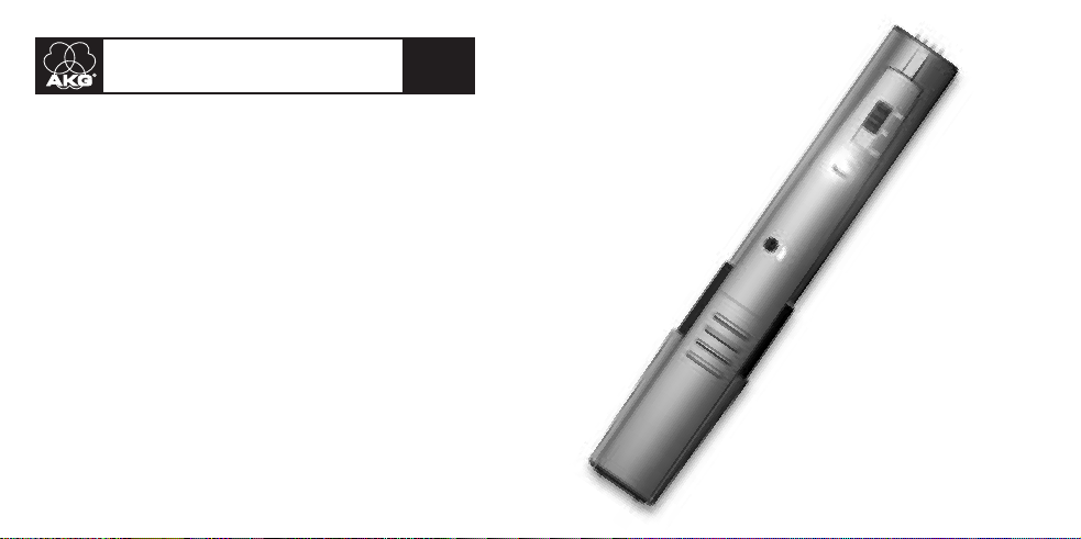
TM 40
transmitter module
Page 2
1 Sicherheit und
Umwelt
1.1 Sicherheit
1. Setzen Sie das Gerät nicht direkter
Sonneneinstrahlung, starker Staubund Feuchtigkeitseinwirkung, Regen,
Vibrationen oder Schlägen aus.
1.2 Umwelt
1. Entsorgen Sie verbrauchte Batterien
und Akkus immer gemäß den jeweils
geltenden Entsorgungsvorschriften.
Werfen Sie Batterien oder Akkus
weder ins Feuer (Explosionsgefahr)
noch in den Restmüll.
2. Wenn Sie das Gerät verschrotten, entfernen Sie die Batterien bzw. Akkus,
trennen Sie Gehäuse, Elektronik und
Kabel und entsorgen Sie alle
Komponenten gemäß den dafür geltenden Entsorgungsvorschriften.
2
2 Beschreibung
2.1 Einleitung
ein Produkt aus dem Hause AKG entschieden haben. Bitte lesen Sie die
Bedienungsanleitung aufmerksam
durch, bevor Sie das Gerät benützen,
und bewahren Sie die Bedienungsanleitung sorgfältig auf, damit Sie jederzeit nachschlagen können. Wir wünschen Ihnen viel Spaß und Erfolg!
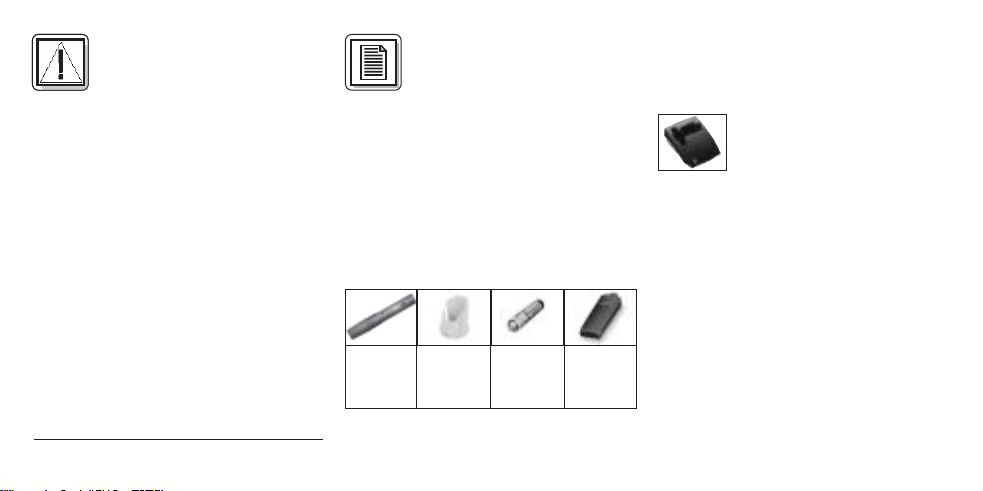
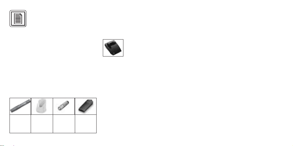
2.2 Lieferumfang
Kontrollieren Sie bitte, ob die
Verpackung alle oben angeführten Teile
Vielen Dank, dass Sie sich für
1 Sender-
modul
TM 40
1 Ladeadapter
CA 40
1 Batterie
Größe
AAA
1 Batterie-
deckel
(schwarz)
enthält. Falls etwas fehlt, wenden Sie
sich bitte an Ihren AKG-Händler.
2.3 Empfohlenes Zubehör
Ladestation CU 40
2.4 Beschreibung
Der TM 40 ist ein Sendermodul der Serie
WMS 40 microtools, das speziell zum
direkten Anstecken an die Mikrofone
M
D 880
, D 3700M, D 3800M, C 900Mund
C 5900Mentwickelt wurde.
Der TM 40 arbeitet auf einer fixen,
quarzstabilisierten Trägerfrequenz im
UHF-Trägerfrequenzbereich von 710 bis
865 MHz.
Die Farbe des Batteriefachdeckels entspricht der Trägerfrequenz des
Sendermoduls. Sie können den Batteriefachdeckel aber auch gegen den mitge-
Page 3
lieferten schwarzen Ersatzdeckel austauschen.
See Manual Supplement
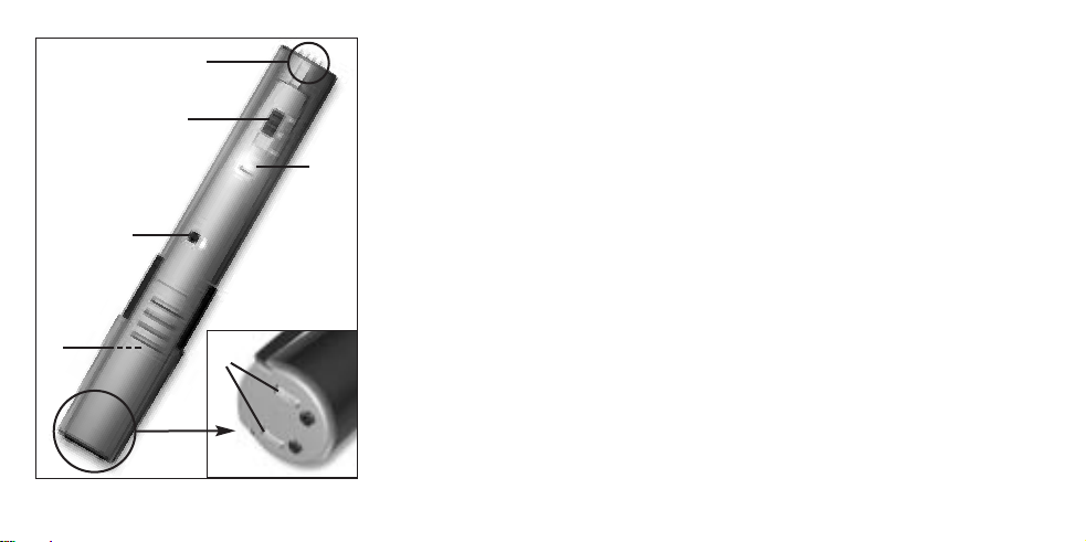
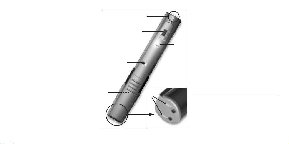
Abb. 1: Bedienelemente TM 40
2.5 Bedienelemente (siehe Abb. 1)
1 ON/MUTE/OFF: Dieser Schiebe-
schalter hat drei Stellungen:
ON: Die Spannungsversorgung für
das Sendermodul ist eingeschaltet.
M: Das vom Mikrofon kommende
Audiosignal ist stummgeschaltet,
Spannungsversorgung und HFTrägerfrequenz bleiben jedoch eingeschaltet. Dadurch wird der Empfänger
trotz abgeschaltetem Mikrofon nicht
durch andere Sender gestört.
OFF: Die Spannungsversorgung für
das Sendermodul ist ausgeschaltet.
2 Batteriefach für 1 Stk. 1,5 V-Batterie
Größe AAA (mitgeliefert).
Die Farbe des Batteriefachdeckels
zeigt die Trägerfrequenz des Senders
an:
3
Page 4
3 Kontroll-LED: Diese LED zeigt den
Ladezustand der Batterie an.
LED leuchtet beim Einschalten kurz
auf und erlischt wieder: Batterie in
Ordnung.
LED leuchtet konstant: Batterie in ca.
60 Minuten erschöpft.
4 Eingangspegelregler: Stellt die
Empfindlichkeit des Audioeingangs ein.
5 Ladekontakte zum Aufladen eines
Akkus im Batteriefach mit Hilfe der
optionalen Ladestation CU 40.
6 Kontakte: Die Kontakte an der
Oberseite des Sendermoduls stellen
automatisch die elektrische Verbindung zum Mikrofon her.
4
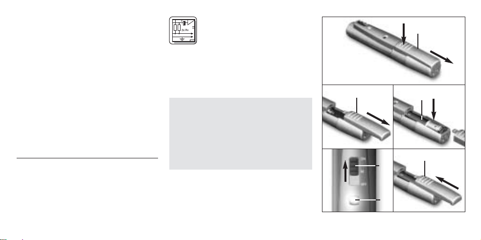
3 Inbetriebnahme
3.1 Batterie einlegen/
austauschen und testen
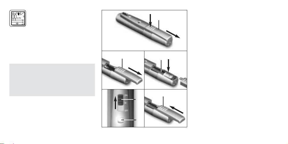
Siehe Abb. 2:
1. Drücken Sie den Schnapphaken am
Batteriefachdeckel (1) nach unten.
2. Ziehen Sie den Batteriefachdeckel (1)
nach unten vom Sendermodul ab.
Wichtig: Der Schaumstoffpolster an der
Innenseite des Batteriefachdeckels
(1) fixiert die Batterie in ihrer Position.
Entfernen Sie den Schaumstoffpolster nicht, da die Batterie ansonsten nicht richtig im Batteriefach
fixiert ist und Klappergeräusche verursachen kann.
3. Legen Sie die mitgelieferte bzw. neue
Batterie (2) wie in Abb. 2 gezeigt in
das Bateriefach ein.
4. Stellen Sie den ON/MUTE/OFFSchalter (3) auf ON.
1
2 3
54
Abb. 2: Batterie einlegen
Page 5
Die Kontroll-LED (4)blitzt kurz auf. Wenn
die Batterie in gutem Zustand ist, erlischt
die Kontroll-LED (4)wieder.
Wenn die Kontroll-LED (4)zu leuchten
beginnt, ist die Batterie in ca. 60 Minuten
erschöpft. Tauschen Sie die Batterie
möglichst bald gegen eine frische aus.
Wenn die Kontroll-LED (4)nicht aufblitzt, ist die Batterie erschöpft.
Legen Sie eine neue Batterie ein.
5. Schieben Sie den Batteriefachdeckel (1) gegen die Pfeilrichtung auf
das Sendermodul, bis der Batteriefachdeckel (1) einrastet.
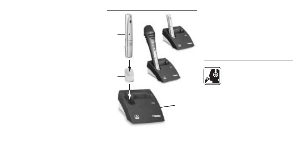
3.2 Betrieb mit Akku (siehe Abb. 3)
Sie können das Sendermodul anstelle
einer normalen Baterie auch mit einem
1,5 V-Akku betreiben.
Wir empfehlen NiMH-Akkus des Typs
SANYO HR-4U (650 mAh) oder
Panasonic Rechargeable PRO+
(550 mAh).
Abb. 3: Akku aufladen mit optionaler
Ladestation CU 40
Zum Aufladen des Akkus brauchen Sie
nur das Sendermodul (1) mit dem
Ladeadapter (2) wie in Abb. 3 gezeigt in
die optionale Ladestation CU 40 (3) zu
stellen.
Nähere Hinweise dazu finden Sie in der
Bedienungsanleitung der Ladestation
CU 40.
4 Anwendung
4.1 Empfohlene Mikrofone
an folgende Mikrofone anstecken:
D 880
C 5900M.
4.2 Sender anstecken und
abziehen
Siehe Bedienungsanleitung Ihres
Mikrofons.
Sie können das Sendermodul
M
, D 3700M, D 3800M, C 900Mund
5
Page 6

4.3 Pegel einstellen (siehe Abb. 1)
1. Kontrollieren Sie, ob der Empfänger
mit demselben Farbcode gekennzeichnet ist wie der Sender.
2. Drehen Sie den Eingangspregelregler
(4) am Sendermodul mit einem kleinen Schraubenzieher bis zur Mitte
zwischen linkem und rechtem
Anschlag auf.
3. Schalten Sie das Sendermodul ein, in
dem Sie den ON/MUTE/OFFSchalter (1) auf ON stellen.
4. Schalten Sie den Empfänger und die
Audioanlage ein.
5. Singen oder sprechen Sie in das
Mikrofon.
6. Sollte Ihre Stimme in den Lautsprechern verzerrt klingen, drehen
Sie den Eingangspegelregler (4) soweit
gegen den Uhrzeigersinn zurück, bis
Sie keine Verzerrung mehr hören.
Sollte Ihre Stimme in den Lautsprechern zu leise klingen, drehen
6
Sie den Eingangspegelregler (4) im
Uhrzeigersinn auf. Falls die Lautsprecher infolge akustischer Rückkopplung zu pfeifen beginnen, drehen Sie den Eingangspegelregler (4)
sofort wieder zurück, bis das Pfeifen
aufhört.
4.4 Mikrofontechnik
Hinweise zur Mikrofontechnik, insbesondere Besprechungsabstand, Naheffekt
und Rückkopplung, finden Sie in der
Bedienungsanleitung Ihres AKGMikrofons.
4.5 Fehlerbehebung
Hinweise zur Fehlerbehebung finden
Sie in der Bedienungsanleitung des
Empfängers.
5 Reinigung
Reinigen Sie das Gehäuse des
Sendermoduls mit einem mit
Wasser befeuchteten Tuch.
Page 7
6 Technische Daten
Trägerfrequenz 710 - 865 MHz
Modulation FM
Audioübertragungsbandbreite 40 - 20.000 Hz
Frequenzstabilität (-10°C bis +50°C) ±15 kHz
Nennhub 15 kHz
Klirrfaktor bei 1 kHz typ. 0,8%
Kompander integriert
Signal/Rauschabstand typ. 103 dB(A)
HF-Ausgangsleistung typ. 5 mW
Stromaufnahme typ. 75 mA
Spannungsversorgung 1 x 1,5 V-Batterie Größe AAA
Betriebszeit >11 h (Batterie), >6 h (Akku)
Audio-Eingangspegel für Nennhub 300 mV/1 kHz
Abmessungen (BxTxH) Länge: 125 mm, ø: 26 mm
Nettogewicht 30 g
Dieses Produkt entspricht den Normen EN 300422-2 V1.1.1; EN 301489-9 V1.3.1;
EN 60065:2002; EN 50371:2002.
7
Page 8
This equipment has been tested and
FCC Statement
found to comply with the limits for a Class
B digital device, pursuant to Parts 74, 15,
and 90 of the FCC Rules. These limits are
designed to provide reasonable protection against harmful interference in a residential installation. This equipment generates, uses, and can radiate radio frequency energy and, if not installed and
used in accordance with the instructions,
may cause harmful interference to radio
communications. However, there is no
guarantee that interference will not occur
in a particular installation. If this equipment does cause harmful interference to
radio or television reception, which can
be determined by turning the equipment
off and on, the user is encouraged to try
to correct the interference by one or more
of the following measures:
• Reorient or relocate the receiving
antenna.
8
• Increase the separation between the
equipment and the receiver.
• Connect the equipment into an outlet
on a circuit different from that to
which the receiver is connected.
• Consult the dealer or an experienced
radio/TV technician for help.
Shielded cables and I/O cords must be
used for this equipment to comply with
the relevant FCC regulations.
Changes or modifications not expressly
approved in writing by AKG Acoustics
may void the user’s authority to operate
this equipment.
This device complies with Part 15 of the
FCC Rules. Operation is subject to the
following two conditions: (1) this device
may not cause harmful interference, and
(2) this device must accept any interference received, including interference
that may cause undesired operation.
1 Safety and
Environment
1.1 Safety
1. Do not expose the equipment to
direct sunlight, excessive dust, moisture, rain, mechanical vibrations, or
shock.
1.2 Environment
1. Be sure to dispose of used batteries
as required by local waste disposal
rules. Never throw batteries into a fire
(risk of explosion) or garbage bin.
2. When scrapping the equipment,
remove the batteries, separate the
case, circuit boards, and cables, and
dispose of all components in accordance with local waste disposal rules.
Page 9
2 Description
2.1 Introduction
Dear Customer:
Thank you for purchasing an AKG
product. This Manual contains important
instructions for setting up and operating
your equipment. Please take a few
minutes to read the instructions below
carefully before operating the equip-
ment. Please keep the Manual for future
reference. Have fun and impress your
audience!
2.2 Unpacking
1 TM 40
transmitter
module
1 CA 40
charging
adapter
1 AAA
size bat-
tery
1
black
battery
cover
Check that the package contains all the
parts listed above. If anything is missing,
please contact your AKG dealer.
2.3 Optional Accessories
CU 40 charger
2.4 Description
The TM 40 is a WMS 40 microtools
Series miniature transmitter module
specifically designed for direct connection to the D 880
M
, D 3700M, D 3800M,
C 900M, and C 5900Mmicrophones.
The TM 40 operates on a single fixed,
quartz stabilized carrier frequency in the
710 MHz to 865 MHz UHF band.
The color of the battery cover indicates
the carrier frequency of your transmitter.
Yo u can replace the color code battery
cover with the supplied black replacement cover.
2.5 Controls (Refer to fig. 1)
1 ON/MUTE/OFF: This slide switch
provides three positions:
ON: Power to the transmitter module
is on.
M: The signal delivered by the microphone is muted while power and the
RF carrier frequency remain on. This
prevents the receiver from responding to interference from other transmitters.
OFF: Power to the transmitter module is off.
2 Battery compartment for one 1.5-V
AAA size battery (supplied).
The color of the battery compartment
cover indicates the carrier frequency
of your transmitter module:
9
Page 10
2.5 Controls (Refer to fig. 1)
1 ON/MUTE/OFF: This slide switch
provides three positions:
ON: Power to the transmitter module
is on.
M: The signal delivered by the microphone is muted while power and the
RF carrier frequency remain on. This
prevents the receiver from responding to interference from other transmitters.
OFF: Power to the transmitter module is off.
2 Battery compartment for one 1.5-V
AAA size battery (supplied).
The color of the battery compartment cover indicates the carrier frequency of your transmitter module:
See Manual Supplement
10
Fig. 1: TM 40 controls.
3 Status LED: Indicates battery status.
LED flashes momentarily upon switching
ON and extinguishes: battery is OK.
LED lights constantly: battery will be
dead in about 60 minutes.
4 Input Gain: This rotary pot sets the
sensitivity of the transmitter module’s
audio section.
5 Charging contacts for charging a
rechargeable battery inside the battery compartment using the optional
CU 40 charger.
6 Contacts: The contacts at the upper
end of the transmitter module will automatically establish all electrical connections to the microphone.
Page 11
3 Setting Up
3.1 Inserting/Replacing and
Testing the Battery
Refer to fig. 2:
1. Depress the snap hook on the battery
compartment lid (1).
2. Pull the battery compartment lid (1)
down to remove it from the transmitter
module.
Important: The foam pad on the inside
of the battery compartment lid (1)
holds the battery in place. Do not
remove the foam pad. If you do, the
battery will not be held in place properly and may cause a rattling noise.
3. If there is a dead or defective battery
inside the battery compartment,
remove the battery.
4. Insert the supplied or new battery (2)
into the battery compartment as
shown in fig. 2.
1
2 3
54
Fig. 2: Inserting the battery.
5. Set the ON/MUTE/OFF switch (3) to ON.
The status LED (4) will flash momentarily. If the battery is in good condition,
the status LED (4) will extinguish.
If the status LED (4) lights constantly
the battery will be dead within about
60 minutes. Replace the battery with
a new one as soon as possible.
If the status LED (4) fails to flash
momentarily the battery is dead.
Insert a new battery.
6. Slide the battery compartment lid (1)
onto the transmitter module against
the direction of the arrow to the point
that the lid (1) will click shut.
3.2 Using Rechargeable Batteries
Refer to fig. 3:
Instead of dry batteries, you can also
use a 1.5-V rechargeable battery to
power the transmitter module. We recommend SANYO HR-4U (650 mAh) or
Panasonic Rechargeable PRO+
11
Page 12
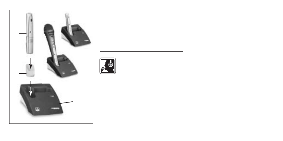
Fig. 3: Using the CU 40 optional charger.
12
(550 mAh) NiMH rechargeable batteries.
To charge the battery, insert the transmitter module (1) into the CA 40 adapter
(2) and the adapter into the optional CU
40 charger (3) as shown in fig. 3.
For details, refer to the CU 40 charger
manual.
4 Operating Notes
4.1 Recommended
Microphones
You can connect the transmitter
to the following microphones: D 880
D 3700M, D 3800M, C 900M, and
C 5900M.
4.2 Connecting and Disconnecting
the Transmitter
Refer to the instruction manual of your
microphone.
M
,
4.3 Setting Levels (Refer to fig. 1)
1. Check that the receiver is marked
with the same color code as the
transmitter module.
2. Use a small screwdriver to turn the
input gain control (4) on the transmitter module to a position halfway
between the left and right stops.
3. Set the ON/MUTE/OFF switch (1) to
ON to switch power to the transmitter
module on.
4. Switch power to your sound system
or amplifier on.
5. Speak or sing into the microphone.
6. If your voice sounds distorted on the
loudspeakers turn the input gain control (4) down CCW to the point that
you will hear no more distortion.
If your voice sounds too quiet on the
loudspeakers, turn the input gain
control (4) up CW. If the loudspeakers
start howling due to acoustic feedback, immediately turn the input gain
Page 13

control (4) back down to the point
that the howling will stop.
4.4 Microphone Technique
For detailed hints on how to use a vocal
microphone, particularly with regard to
working distance, proximity effect, and
feedback, refer to the instruction manual
of your AKG microphone.
4.5 Troubleshooting
For troubleshooting hints, refer to your
receiver manual.
5 Cleaning
To clean the transmitter module
case, use a soft cloth moist-
ened with water.
13
Page 14

6 Specifications
Carrier frequency range 710 to 865 MHz
Audio bandwidth 40 to 20,000 Hz
Frequency stability (-10°C to +50°C) ±15 kHz
Rated deviation 15 kHz (SP1, SP2: 13.5 kHz)
T.H.D. at 1 kHz typ. 0.8%
Compander integrated
Signal/noise ratio typ. 103 dB(A)
RF output typ. 5 mW
Current consumption typ. 75 mA
Power requirement single 1.5-V AAA size battery
Battery life >11 hours (dry battery)
Audio input level for rated deviation 300 mV/1 kHz
Size (WxDxH) length: 125 mm (5 in.);
Net weight 30 g (1.1 oz.)
This product complies with the following standards: EN 300422-2 V1.1.1;
EN 301489-9 V1.3.1; EN 60065:2002; EN 50371:2002.
14
Modulation FM
>6 hours (rechargeable battery)
dia.: 26 mm (1 in.)
Page 15

1 Sécurité et
écologie
1.1. Sécurité
1. Ne placez jamais l’appareil à un
endroit où il risque d’être exposé
directement au soleil, à une atmosphère poussiéreuse, à l’humidité, à
la pluie, aux vibrations ou aux
secousses.
1.2. Ecologie
1. Conformez-vous aux règlements en
vigueur pour la mise au rebut des
piles usées. Ne mettez jamais des
piles ni au feu (risque d’explosion) ni
aux ordures ménagères.
2. Si vous mettez l'appareil à la ferraille,
enlevez les piles ou les accus, séparez le boîtier, l'électronique et les
câbles et éliminez les différents éléments conformément aux règlements
en vigueur.
2 Description
2.1 Introduction
choisi un produit AKG.
Pour profiter au maximum des avantages que vous offre le WMS 40, lisez
très attentivement ce mode d’emploi
avant la mise en service de l’appareil.
Conservez soigneusement le mode
d’emploi pour pouvoir le consulter
lorsque vous vous posez des questions.
Nous vous souhaitons beaucoup de
succès.
2.2. Equipement fourni
Contrôlez si le carton contient bien tous
Nous vous remercions d’avoir
1 module
émetteur
TM 40
1 adapta-
teur CA 40
sion AAA
1 pile
dimen-
1
couver-
cle noir
les éléments énumérés ci-dessus. Si ce
n’est pas le cas, veuillez contacter votre
distributeur AKG.
2.3 Accessoires optionnels
Chargeur CU 40
2.4 Description
Le TM 40 est un module émetteur minia-
ture de la gamme WMS 40 microtools,
spécialement conçu pour être branché
directement sur les micros D 880
D 3700M, D 3800M, C 900Met C 5900M.
Le TM 40 fonctionne sur une porteuse
fixe stabilisée par quartz dans la gamme
de fréquences porteuses UHF de 710 à
865 MHz.
La couleur du couvercle du compartiment de la pile correspond à la fréquence porteuse du module émetteur. Vous
15
M
,
Page 16

pouvez cependant remplacer le couvercle couleur par le couvercle de
rechange noir fourni.
2.5 Eléments de commande
1 ON/MUTE/OFF: Ce curseur peut
occuper trois positions :
ON : Le module émetteur est sous
tension.
M : Le signal audio venant du micro
est sur muet mais le module émetteur
reste sous tension et sur la porteuse
HF. Ceci permet de couper le micro
sans que le récepteur ne soit perturbé par d’autres émetteurs.
OFF : Le module émetteur n’est pas
sous tension.
2Compartiment de la pile pour une
pile de 1,5 V, dimension AAA
(fournie).
La couleur du couvercle correspond
à la porteuse du module émetteur :
16
(Cf. Fig. 1)
2.5 Eléments de commande
1)
1 ON/MUTE/OFF: Ce curseur peut
occuper trois positions :
ON : Le module émetteur est sous
tension.
M : Le signal audio venant du micro
est sur muet mais le module émetteur reste sous tension et sur la porteuse HF. Ceci permet de couper le
micro sans que le récepteur ne soit
perturbé par d’autres émetteurs.
OFF : Le module émetteur n’est pas
sous tension.
2 Compartiment de la pile pour une
pile de 1,5 V, dimension AAA
(fournie).
La couleur du couvercle correspond
à la porteuse du module émetteur :
See Manual Supplement
(Cf. Fig.
Fig. 1 : Eléments de commande du TM 40
Page 17

3 LED témoin : Cette LED indique
l’usure de la pile.
La LED lance un éclair quand on met
le module émetteur sous tension puis
s’éteint aussitôt : la pile est en bon
état.
La LED reste allumée : la pile n’assure plus que 60 minutes d’autonomie.
4 Potentiomètre d’entrée : règle la
sensibilité de l’entrée audio.
5 Contacts pour charger un accu
dans le compartiment de la pile à l’aide du chargeur optionnel CU 40.
6Contacts : Les contacts sur le haut
du module émetteur établissent automatiquement la connexion électrique
avec le microphone.
3 Mise en service
3.1 Mise en place/remplacement et essai de la pile
Voir Fig. 2 :
1. Poussez le fermoir du couvercle du
compartiment de la pile (1) vers le
bas.
2. Enlevez le couvercle du compartiment de la pile (1) en le faisant glisser
vers le bas.
Important : La plaque de mousse à
l’intérieur du couvercle du compartiment de la pile (1) maintient la pile en
position. N’enlevez pas cette plaque,
sinon la pile ne serait pas maintenue
correctement et risquerait de provoquer des bruits importuns.
3. Enlevez, le cas échéant, la pile épuisée ou défectueuse se trouvant dans
le compartiment.
4. Mettez la pile fournie ou la nouvelle
1
2 3
Fig. 2 : Mise en place de la pile
54
17
Page 18

pile (2) dans le compartiment comme
indiqué à la Fig. 2.
5. Faites occuper au curseur
ON/MUTE/OFF (3) la position ON.
La LED témoin (4) lance un éclair. Si
la pile est en bon état, la LED (4)
s’éteint aussitôt.
Si la LED (4) reste allumée, la pile
n’assure plus que 60 minutes d’autonomie. Remplacez-la dès que possible par une pile fraîche.
Si la LED (4) ne s’allume pas, la pile
est épuisée et doit être changée.
6. Remettez le couvercle du compartiment de la pile (1) sur le module
émetteur en le faisant glisser dans le
sens inverse de la flèche jusqu’à
enclenchement.
3.2 Fonctionnement sur accu
Voir Fig. 3:
Au lieu d’une pile normale, vous pouvez
également utiliser un accu de 1,5 V.
18
Fig. 3 : Recharge de l’accu à l’aide du
chargeur optionnel CU 40
Nous recommandons les accus NiMH,
type SANYO HR-4U (650 mAh) ou
Panasonic Rechargeable PRO+ (550 mAh).
Pour recharger l’accu il suffit d’introduire
le module émetteur (1) avec l'adaptateur
CA 40 (2) dans le chargeur optionnel CU
40 (3) comme indiqué à la Fig. 3.
Pour plus de détails, veuillez consulter le
mode d’emploi du chargeur CU 40.
4 Mode opératoire
4.1 Microphones
recommandés
Vous pouvez brancher le module émetteur sur les microphones suivants : D 880
et C 5900M.
4.2 Branchement et débranchement du module émetteur
Veuillez vous reporter au mode d’emploi
de votre microphone.
M
, D 3700M, D 3800M, C 900
M
Page 19

4.3 Réglage de niveau (voir Fig. 1)
1. Vérifiez si le récepteur a bien le même
code couleur que le module émetteur.
2. A l’aide d’un petit tournevis, réglez le
potentiomètre d’entrée (4) du module
émetteur sur la position médiane, à
égale distance des butées droite et
gauche.
3. Mettez le module émetteur sous tension en amenant le curseur
ON/MUTE/OFF (1) sur ON.
4. Mettez le récepteur et l’équipement
audio sous tension.
5. Chantez ou parlez dans le micro.
6. Si votre voix arrive déformée aux
haut-parleurs, faites tourner le potentiomètre d’entrée (4) dans le sens
inverse des aiguilles de la montre jusqu’à disparition des distorsions.
Si votre voix arrive sous un niveau
trop faible aux haut-parleurs, faites
tourner le potentiomètre d’entrée (4)
dans le sens des aiguilles de la
montre. Si les haut-parleurs se mettent à siffler parce qu’il y a du larsen
tournez aussitôt le réglage (4) dans le
sens inverse jusqu’à ce que les sifflements s’arrêtent.
4.4 Technique du micro
Vous trouverez dans le mode d’emploi
de votre micro AKG toutes les indications relatives à la technique du micro,
en particulier celles concernant la distance du micro aux lèvres, l’effet de
proximité et le larsen.
4.5 Dépannage
Vous trouverez les instructions relatives
au dépannage dans le mode d’emploi de
votre récepteur.
5 Nettoyage
Le boîtier du module émetteur
se nettoie avec un chiffon
humecté d’eau.
19
Page 20

6 Caractéristiques techniques
Fréquence porteuse 710 - 865 MHz
Bande passante audio 40 - 20.000 Hz
Stabilité de fréquence (entre -10°C et +50°C) ±15 kHz
Excursion nominale 15 kHz (SP1, SP2 : 13,5 kHz)
Distorsion typ. (par harmonique) pour 1 kHz 0,8 %
Compresseur-expanseur intégré
Rapport signal sur bruit typ. 103 dB (A)
Puissance sortie HF typ. 5 mW
Consommation typ. 75 mA
Alimentation 1 pile de 1,5 V, dimension AAA
Autonomie > 11 h (pile), > 6 h (accu)
Niveau d’entrée audio pour l’excursion nominale 300 mV/1kHz
Dimensions (l x p x h) longueur: 125 mm
Poids net 30 g
Ce produit est conforme aux normes EN 300422-2 V1.1.1; EN 301489-9 V1.3.1;
EN 60065:2002; EN 50371:2002.
20
Modulation FM
diamètre: 26 mm
Page 21

1 Sicurezza ed
ambiente
1.1 Sicurezza
1. Non esponete l’apparecchio direttamente al sole, alla polvere e all'umidità,
alla pioggia, a vibrazioni o a colpi.
1.2 Ambiente
1. Smaltite le batterie usate e gli accumulatori usati sempre conformemente alle norme di smaltimento rispettivamente vigenti. Non gettate le batterie o gli accumulatori nel fuoco
(pericolo di esplosione) o nei rifiuti
residui.
2. Se rottamate l’apparecchio, togliete
le batterie risp. gli accumulatori,
separate scatola, elettronica e cavi e
smaltite tutti i componenti conformemente alle norme di smaltimento
vigenti per essi.
2 Descrizione
2.1 Introduzione
prodotto dell‘AKG. Leggete per favore
attentamente le istruzioni per l’uso
prima di usare l’apparecchio e conservate le istruzioni per l’uso per poterle
consultare in caso di necessità. Vi auguriamo buon divertimento e molto successo!
2.2. In dotazione
1 modulo di
Controllate per favore se la confezione
contiene tutti i componenti di cui sopra.
Vi ringraziamo di aver scelto un
trasmissio-
ne TM 40
1 adattato-
re CA 40
dimensione
1 batteria
AAA
1 coperchio
batteria
(nero)
Se manca qualcosa rivolgetevi al vostro
rivenditore AKG.
2.3 Accessori raccomandati
Stazione di carica CU 40
2.4 Descrizione
Il TM 40 è un modulo di trasmissione in
miniatura della serie WMS 40 micro-
tools, sviluppato appositamente per il
collegamento diretto ai microfoni
M
D 880
, D 3700M, D 3800M, C 900Me
C 5900M.
Il TM 40 funziona su una frequenza por-
tante fissa, stabilizzata a quarzo, nella
gamma delle frequenze UHF da 710 a
865 MHzo.
Il colore del coperchio dello scomparto
batteria corrisponde alla frequenza portante del modulo di trasmissione. Potete
anche sostituire il coperchio dello scom-
21
Page 22

parto batteria con il coperchio di riserva
nero in dotazione.
See Manual Supplement
Fig. 1: Elementi di comando del TM 40
22
2.5 Elementi di comando (vedi fig. 1)
1 ON/MUTE/OFF: Questo interruttore
a scorrimento ha tre posizioni:
ON: L’alimentazione del modulo di
trasmissione è inserita.
M: Il segnale audio proveniente dal
microfono è silenziato, la tensione
d’alimentazione e la frequenza portante RF rimangono inseriti. In questo
modo il modulo di trasmissione non
viene disturbato da altri trasmettitori
anche quando il microfono non è
acceso.
OFF: L’alimentazione del modulo di
trasmissione è spenta.
2 Scomparto batteria per 1 batteria da
1,5 V dimensione AAA (in dotazione).
Il colore del coperchio indica la frequenza portante del modulo di trasmissione:
Page 23

3 LED di controllo: Questo LED indica
lo stato di carica della batteria.
Il LED si accende brevemente al
momento dell’accensione e si
spegne subito dopo: la batteria è o.k.
Il LED rimane acceso permanentemente: la batteria si esaurirà nei prossimi 60 minuti circa.
4 Regolatore del livello d’ingresso:
regola la sensibilità dell’ingresso audio.
5 Contatti di carica per caricare un
accumulatore nello scomparto batteria con l’aiuto dell’opzionale stazione
di carica CU 40.
6 Contatti: I contatti sulla parte supe-
riore del modulo di trasmissione realizzano automaticamente il collegamento elettrico con il microfono.
3 Messa in funzione
3.1 Inserire/sostituire e
testare la batteria
Vedi fig. 2:
1. Premete verso il basso il gancio ad
innesto disposto sul coperchio dello
scomparto batteria (1).
2. Sfilate il coperchio dello scomparto
batteria (1) dal modulo di trasmissione tirando il coperchio verso il basso.
Importante: Il cuscinetto in espanso fis-
sato sul lato interno del coperchio
dello scomparto batteria (1) fissa la
batteria nella sua posizione. Non
togliete il cuscinetto perché altrimenti la batteria non è fissata bene nello
scomparto e può causare rumori.
3. Se c’è una batteria esausta o difettosa nello scomparto batteria, toglietela.
4. Inserite la batteria in dotazione o una
1
2 3
Fig. 2: Come inserire la batteria
54
23
Page 24

nuova (2) nello scomparto batteria
come indicato nella fig. 2.
5. Portate l’interruttore ON/MUTE/OFF
(3) in posizione ON.
Il LED di controllo (4) si accende brevemente. Se la batteria è in buono
stato, il LED di controllo (4) si spegne
subito.
Se il LED di controllo (4) si accende
rimanendo acceso, la batteria si
esaurirà nei prossimi 60 minuti circa.
Sostituitela al più presto con una
nuova.
Se il LED di controllo (4) non si
accende nemmeno brevemente, la
batteria è esausta. Inserite una batteria nuova.
6. Mettete il coperchio dello scomparto
batteria (1) sul modulo di trasmissione, facendolo scorrere contro la direzione della freccia fin quando il
coperchio (1) scatta.
24
Fig. 3: Come caricare l’accumulatore
con l’opzionale stazione di carica CU 40
3.2 Esercizio con accumulatori
Vedi fig. 3:
Potete far funzionare il modulo di trasmissione anche con un accumulatore
da 1,5 V al posto di una batteria. Vi raccomandiamo di usare accumulatori
NiMH del tipo SANYO HR-4U (650 mAh)
oppure del tipo Panasonic Rechargeable
PRO+ (550 mAh).
Per caricare l’accumulatore, basta piazzare il modulo di trasmissione (1) con l’adattatore CA 40 (2) nell'opzionale stazione di carica CU 40 (3) come indicato
nella fig. 3.
Per indicazioni più dettagliate consultate
le istruzioni per l’uso della stazione di
carica CU 40.
4 Impiego
4.1 Microfoni raccomandati
Potete collegare il modulo di
trasmissione ai seguenti
Page 25

microfoni: D 880M, D 3700M, D 3800M,
C 900Me C 5900M.
4.2 Come inserire e sfilare il
modulo di trasmissione (vedi fig. 4)
Vedi le istruzioni per l'uso del vostro
microfono.
4.3 Come regolare il livello (vedi fig. 1)
1. Controllate se il ricevitore ha lo stesso codice a colore del modulo di trasmissione.
2. Aprite il regolatore del livello d‘ingresso (4) sul modulo di trasmissione
girandolo con un piccolo cacciavite
fin quando si trova al centro tra arresto sinistro e quello destro.
3. Inserite il modulo di trasmissione portando l’interruttore ON/MUTE/OFF (1)
in posizione ON.
4. Inserite il ricevitore e l’impianto
audio.
5. Cantate o parlate nel microfono.
6. Se la vostra voce viene riprodotta
distorta dagli altoparlanti, portate
indietro il regolatore del livello d’ingresso (4) in senso antiorario fin
quando non sentite più distorsioni.
Se la vostra voce viene riprodotta
troppo bassa dagli altoparlanti, portate avanti il regolatore del livello d’ingresso (4) girandolo in senso orario.
Se gli altparlanti cominciano a
fischiare a causa del feedback acustico, riportate subito indietro il regolatore del livello d’ingresso (4) fin
quando il fischio cessa.
4.4 Tecnica microfonica
Le indicazioni sulla tecnica microfonica,
in particolare per quanto alla distanza
del microfono dalla bocca, all’effetto di
prossimità e al feedback, sono contenute nelle istruzioni per l’uso del vostro
microfono AKG.
4.5 Difetti e rimedi
Le indicazioni come rimediare a difetti
sono contenute nelle istruzioni per l’uso
del vostro ricevitore.
5 Pulizia
Pulite la scatola del modulo di
trasmissione con un panno
inumidito d’acqua.
25
Page 26

6 Dati tecnici
Frequenza portante 710 - 865 MHz
Gamma di trasmissione audio 40 - 20.000 Hz
Stabilità della frequenza (da -10°C a +50°C) ±15 kHz
Deviazione nominale 15 kHz (SP1, SP2: 13,5 kHz)
Fattore di distorsione ad 1 kHz tip. 0,8%
Compander integrato
Rapporto segnale/rumore tip. 103 dB(A)
Potenza d’uscita RF tip. 5 mW
Assorbimento tip. 75 mA
Alimentazione 1 batteria da 1,5 V
Durata d’esercizio >11 h (batteria),
Livello d’ingresso audio per deviazione nominale 300 mV/1 kHz
Dimensioni (larghezza x profondità x altezza) lunghezza: 125 mm
Peso netto 30 g
Questo prodotto corrisponde alle norme EN 300422-2 V1.1.1; EN 301489-9 V1.3.1;
EN 60065:2002; EN 50371:2002.
26
Modulazione FM
dimensione AAA
>6 h (accumulatore)
diametro: 26 mm
Page 27

1 Seguridad y medio
ambiente
1.1 Seguridad
1. No exponer el aparato directamente
al sol, a polvo o humedad intensos, a
la lluvia, a vibraciones o a golpes.
1.2 Medio ambiente
1. Las pilas y los acumuladores usados
deben eliminarse atendiendo a las
correspondientes disposiciones de
eliminación de residuos vigentes. Las
pilas o acumuladores no deben tirarse ni al fuego (peligro de explosión) ni
a la basura residual.
2. Para desguazar el aparato hay que
sacar las pilas o los acumuladores,
separar la caja, la electrónica y el
cable y proceder a la eliminación de
todos los componentes atendiendo a
las correspondientes disposiciones
de eliminación de residuos vigentes.
2 Descripción
2.1 Introducción
decidido por un producto de la empresa
AKG. Tómese, por favor, unos momentos para leer el Modo de Empleo antes
de usar el aparato. Guarde las instrucciones de empleo en un lugar seguro de
modo que pueda consultarlas si se le
presenta alguna duda. ¡Que se divierta y
que tenga mucho éxito con su nuevo
equipo!
2.2. Volumen de suministros
Sírvase controlar si el embalaje contiene
Muchas gracias por haberse
1 módulo
transmisor
TM 40
1 adaptador CA 40
tamaño
1 pila
AAA
1 tapa de
caja de
pilas (negra)
todas las piezas indicadas arriba. Si falta
algo, le rogamos dirigirse a su distribuidor AKG.
2.3 Accesorios recomendados
Estación de carga CU 40
2.4 Descripción
El TM 40 es un módulo transmisor
miniatura de la serie WMS 40 microto-
ols, desarrollado especialmente para los
micrófonos D 880
D 3800M, C 900My C 5900M.
El TM 40 funciona con una frecuencia
portadora fija estabilizada por cuarzo en
la gama de frecuencias portadoras UHF
de 710 hasta 865 MHz.
El color de la tapa de la caja de pilas
corresponde a la frecuencia portadora
del módulo transmisor. La tapa de la
caja de pilas la puede reemplazar por la
M
, D 3700M,
27
Page 28

Fig. 1: Elementos de mando del TM 40
28
tapa de sustitución negra suministrada.
2.5 Elementos de mando (véase Fig. 1)
1 ON/MUTE/OFF: este conmutador
corredizo tiene tres posiciones:
ON: la alimentación de corriente para
el módulo transmisor está conectada.
M: la señal audio que proviene del
micrófono está en mudo, pero la alimentación de corriente y la frecuencia portadora de AF siguen conectadas. Esto hace que el receptor no se
vea perturbado por otros transmisores a pesar de tener el micrófono
desconectado.
OFF: la alimentación de corriente del
módulo transmisor está desconectada.
2 Caja de pilas para 1 pila de 1,5 V
tamaño AAA (suminstrada).
El color de la tapa indica la frecuencia portadora del módulo transmisor:
See Manual Supplement
Page 29

3 LED de control: este LED indica el
estado de carga de la pila.
El LED se ilumina brevemente al
encender el módulo transmisor y
luego se apaga: la pila está en orden.
El LED se ilumina en forma constante: la pila estará agotada en aprox.
60 minutos.
4 Control de nivel de entrada: ajusta
la sensibilidad de la entrada audio.
5 Contactos de carga para cargar un
acumulador con la estación de carga
opcional CU 40.
6 Cotactos: los contactos en el lado
superior del módulo transmisor establecen automáticamente la conexión
eléctrica con el micrófono.
3 Puesta en
funcionamiento
3.1 Colocar/cambiar y
ensayar la pila (véase Fig. 2)
1. Apriete hacia abajo el gancho de presión de la tapa de la caja de pilas (1).
2. Retire la tapa de la caja de pilas (1)
del módulo transmisor, tirando hacia
abajo.
Importante: el relleno de goma espuma
en el interior de la tapa de la caja de
pilas (1) fija la pila en su posición. ¡El
relleno no se debe quitar, puesto que
de hacerlo, la pila no quedará bien
fijada en la caja, lo que puede producir ruidos de tableteo!
3. Si en la caja de pilas hay una pila descargada o defectuosa, sírvase sacarla.
4. Coloque la pila suministrada o nueva
(2) en la caja de pilas, tal como se
indica en la Fig. 2.
1
2 3
Fig. 2: Introducir la pila
54
29
Page 30

5. Coloque el conmutador ON/MUTE/
OFF (3) en ON.
El LED de control (4) relampaguea
brevemente. Si la pila está en buen
estado, el LED de control (4) se vuelve a apagar.
Cuando el LED de control (4) empieza a iluminarse constantemente, la
pila estará agotada en aprox. 60
minutos. Cambie la pila cuanto antes
por una nueva.
Si el LED de control (4) no relampaguea, la pila está agotada. Coloque
una pila nueva.
6. Empuje la tapa de la caja de pilas (1)
sobre el módulo transmisor en dirección contraria a la flecha, hasta que
quede enclavada.
3.2 Funcionamiento con
acumulador (véase Fig. 3)
El módulo transmisor se puede hacer
funcionar también con un acumulador de
1,5 V en lugar de una pila normal.
30
Fig. 3: Cargar el acumulador con la
estación de carga opcional CU 40
Recomendamos los acumuladores NiMH
del tipo SANYO HR-4U (650 mAh) o
Panasonic Rechargeable PRO+ (550 mAh).
Para cargar el acumulador tiene que
poner el módulo transmisor (1) con el
adaptador CA 40 (2) en la estación de
carga opcional CU 40 (3), tal como se
indica en la Fig. 3.
Puede encontrar más indicaciones al
respecto en el Modo de empleo de la
estación de carga CU 40.
4 Aplicación
4.1 Micrófonos
recomendados
Puede conectar el módulo transmisor a
los siguientes micrófonos: D 880
D 3700M, D 3800M, C 900My C 5900M.
4.2 Conectar y desconectar el
módulo transmisor
Véase el Modo de Empleo de su micrófono.
M
,
Page 31

4.3 Controlar el nivel (véase Fig. 1)
1. Controle si el receptor está marcado
con el mismo código de color que el
módulo transmisor.
2. Gire el control de nivel de entrada (4)
del módulo transmisor con un pequeño desatornillador hasta el centro,
entre el tope izquierdo y derecho.
3. Encienda el módulo transmisor, colocando el conmutador ON/MUTE/OFF
(1) en ON.
4. Encienda el receptor y el equipo
audio.
5. Cante o hable en el micrófono.
6. Si su voz suena distorsionada en los
altavoces, gire el control de nivel de
entrada (4) hacia atrás en sentido
contrario a las agujas del reloj hasta
que ya no oiga ninguna distorsión.
Si su voz suena muy baja en los altavoces, gire el control de nivel de
entrada (4) en sentido de las agujas
del reloj. Si los altavoces empiezan a
silbar debido a la retroalimentación
acústica, gire el control de nivel de
entrada (4) inmediatamente de vuelta
hasta que cese el silbido.
4.4 Técnica microfónica
En los correspondientes Modos de
empleo de sus micrófonos AKG encontrará indicaciones acerca de la técnica
microfónica, sobre todo con respecto a
la distancia de palabra, el efecto de proximidad y la retroalimentación acústica.
4.5 Reparación de desperfectos
Las indicaciones para la reparación de
desperfectos las encuentra en el Modo
de empleo de su receptor.
5 Limpieza
Limpie la caja del módulo transmisor con un paño humedecido
en agua.
31
Page 32

6 Datos técnicos
Frecuencia portadora 710 – 865 MHz
Ancho de banda de transmisión audio 40 – 20.000 Hz
Estabilidad de frecuencia (-10°C hasta +50°C) ±15 kHz
Desviación nominal 15 kHz (SP1, SP2: 13,5 kHz)
Factor de distorsión no lineal con 1 kHz típ. 0,8%
Compansor integrado
Relación señal a ruido típ. 103 dB(A)
Potencia de salida AF típ. 5 mW
Toma de corriente típ. 75 mA
Alimentación de corriente 1 pila de 1,5 V tamaño AAA
Horas de servicio >11 h (pila), >6 h (acumulador)
Nivel de entrada audio para desviación nominal 300 mV/1 kHz
Dimensiones (an x prof x al) longitud: 125 mm
Peso neto 30 g
Este producto corresponde a las normas EN 300422-2 V1.1.1; EN 301489-9 V1.3.1;
EN 60065:2002; EN 50371:2002.
32
Modulación FM
diámetro: 26 mm
Page 33

1 Segurança e meio
ambiente
1.1 Segurança
1. Não exponha o dispositivo à radiação solar, poeira ou umidade, chuva,
vibrações e golpes.
1. Pilhas e acumuladores esgotados
deverão ser eliminados conforme as
respectivas normas estabelecidas
por lei. Não jogue as pilhas no fogo
(perigo de explosão) nem no lixo
doméstico.
2. Quando pretende desfazer-se do
aparelho, remova as pilhas ou os
acumuladores, separe a carcaça, a
eletrônica e os cabos e providencie
que estes serão eliminados conforme
as normas estabelecidas por lei.
2 Descrição
2.1 Introdução
por um produto da AKG. Por favor reserve alguns minutos para ler este manual
antes de acionar este equipamento e
guarde as instruções cuidadosamente
para sempre poder consultá-las em
caso de aparecerem quaisquer perguntas. Divirta-se e bom trabalho!
2.2 Volume de fornecimento
Verifique se a embalagem contém todos
os componentes acima indicados.
Agradecemos a sua preferência
1 módulo
de emissor
TM 40
1 adaptador CA 40
tamanho
1 pilha
AAA
1 tampa
de pilha
(preta)
Caso falte algo, favor entre em contato
com a concessionária da AKG.
2.3 Acessórios recomendados
Carregador CU 40
2.4 Descrição
O TM 40 é um módulo de emissor minia-
turizado da série WMS 40 microtools,
desenvolvido especialmente para ser
conectado diretamente aos microfones
M
D 880
, D 3700M, D 3800M, C 900Me
C 5900M.
O TM 40 funciona numa freqüência por-
tadora fixa estabilizada a cristal na faixa
de freqüência portadora UHF de 710 a
865 MHz.
A cor da tampa do compartimento da
pilha corresponde à freqüência portadora do módulo de emissor. Pode substi-
33
Page 34

tuir a tampa pela tampa de reposição
em cor preta fornecida na embalagem.
See Manual Supplement
Fig. 1: Controles do TM 40
34
2.5 Elementos de controle (Veja fig. 1)
1 ON/MUTE/OFF: esta barra deslizan-
te possui três posições:
ON: a alimentação de corrente do
módulo de emissor está ligada.
M: o sinal de áudio proveniente do
microfone está mudo, a alimentação
de corrente e a freqüência portadora
RF, porém, permanecem ligadas.
Desta forma o módulo de emissor não
é perturbado por outros emissores
embora o microfone esteja desligado.
OFF: a alimentação de corrente do
módulo de emissor está desligada.
2 Compartimento de pilha para 1
pilha de 1,5 V tamanho AAA (fornecida na embalagem).
A cor da tampa do compartimento
indica a freqüência portadora do
módulo de emissor:
Page 35

3 LED de controle: este LED indica o
estado de carga das pilhas.
O LED acende-se brevemente quando liga o aparelho e apaga-se depois:
a pilha está em ordem.
O LED permanece aceso: a pilha estará esgotada dentro de 60 minutos.
4Ajuste do nível de entrada: ajusta a
sensibilidade da entrada de áudio.
5 Contatos de carga para carregar um
acumulador no compartimento da
pilha através do carregador opcional
CU 40.
6 Contatos: os contatos na extremida-
de superior do módulo de emissor
estabelecem automáticamente todas
as conexões elétricas ao microfone.
3 Acionamento
3.1 Colocar/trocar a pilha e
testá-la
Veja fig. 2:
1. Empurre o gancho de engate na
tampa do compartimento da pilha (1)
para baixo.
2. Retire a tampa do compartimento da
pilha (1) do módulo de emissor para
baixo.
Importante: o cubinho de borracha
esponjosa no interior da tampa do
compartimento da pilha (1) fixa a
pilha na sua posição. Não retire o
cubinho de borracha esponjosa porque senão a pilha não está fixada
corretamente no compartimento.
3. Se houver uma pilha gasta ou defeituosa no compartimento da pilha,
retire-a.
4. Coloque a pilha nova ou a pilha (2) for-
1
2 3
Fig. 2: Colocar a pilha
54
35
Page 36

necida na embalagem no compartimento como é mostrado na fig. 2.
5. Posicione o comutador ON/MUTE/
OFF (3) em ON.
O LED de controle (4) acende-se brevemente. Quando a pilha está em
ordem, o LED de controle apaga-se.
Se o LED de controle (4) permanece
aceso a pilha estará esgotada dentro
de ca. 60 minutos Troque-a depressa
por uma pilha nova.
Se o LED de controle (4) não se acender, a pilha está esgotada. Coloque
uma pilha nova.
6. Empurre a tampa do compartimento
da pilha (1) no módulo de emissor
contra o sentido da seta, até a tampa
do compartimento (1) engatar.
Recomendamos acumuladores NiMH do
tipo SANYO HR-4U (650 mAh) ou
Panasonic Rechargeable PRO+ (550 mAh).
Para carregar o acumulador só precisa
colocar o módulo de emissor (1) com o
adaptador CA 40 (2) no carregador
opcional CU 40 (3) como demonstrado
na fig. 3.
Mais informações encontrará no manual
do usuário do carregador CU 40.
4 Operação
4.1 Microfones
recomendados
Pode ligar o módulo de emissor aos
seguintes microfones: D 880
D 3800M, C 900Me C 5900M.
M
, D 3700M,
3.2 Uso com acumulador (Veja fig. 3)
Em vez de usar uma pilha normal, pode
operar o módulo de emissor também
com um acumulador de 1,5 V.
36
Fig. 3: Carregar o acumulador com o
carregador opcional CU 40
4.2 Ligar e retirar o módulo de
emissor
Veja o manual de instruções de seu
microfone.
Page 37

4.3 Ajustar o nível (veja fig. 1)
1. Certifique-se que o receptor está
marcado com a mesma cor do que o
módulo de emissor.
2. Gire o ajuste do nível (4) no módulo
de emissor com uma chave de fenda
pequena até o meio entre os pontos
finais direito e esquerdo.
3. Ligue o módulo de emissor posicionando o comutador ON/MUTE/OFF
(1) em ON.
4. Ligue o receptor e a instalação de
áudio.
5. Cante ou fale no microfone.
6. Se a sua voz aparecer distorcida nos
alto-falantes vire o ajuste do nível de
entrada (4) no sentido anti-horário até
a distorção desaparecer.
Se sua voz soar demasiadamente
baixo, gire o ajuste do nível de entrada (4) no sentido horário. Se os altofalantes começarem a emitir assobios devido a realimentação acústi-
ca, gire o ajuste do nível de entrada
(4) para trás até os assobios desaparecerem.
4.4 Uso do microfone
Dicas para o uso de microfones, sobretudo em relação à distância do microfone, efeito de proximidade e realimentação acústica encontrará no manual
do seu microfone AKG.
4.5 Resolver problemas
Os avisos para resolver problemas
encontrará no manual do usuário do seu
receptor.
5 Limpeza
Limpe a carcaça do módulo de
emissor com um pano molhado
em água.
37
Page 38

6 Dados técnicos
Freqüência portadora 710 - 865 MHz
Largura de banda áudio 40 - 20.000 Hz
Estabilidade de freqüência (-10°C a +50°C) ±15 kHz
Desvio nominal 15 kHz (SP1, SP2: 13,5 kHz)
Distorção não-linear em 1 kHz typ. 0,8%
Compressor/Expansor integrado
Relação sinal/ruído tip. 103 dB(A)
Potência de saída RF tip. 5 mW
Consumo de corrente tip. 75 mA
Alimentação de corrente pilha de 1 x 1,5 V tamanho AAA
Funcionamento >11 h (pilha), >6 h (acumulador)
Nível de entrada para desvio nominal 300 mV/1 kHz
Dimensões (LxPxA) comprimento: 125 mm
Peso neto 30 g
Este produto corresponde às normas EN 300422-2 V1.1.1; EN 301489-9 V1.3.1;
EN 60065:2002; EN 50371:2002.
38
Modulação FM
diâmetro: 26 mm
Page 39

40
Mikrofone · Kopfhörer · Drahtlosmikrofone · Drahtloskopfhörer · Kopfsprechgarnituren · Akustische Komponenten
Microphones · Headphones · Wireless Microphones · Wireless Headphones · Headsets · Electroacoustical Components
Microphones · Casques HiFi · Microphones sans fil · Casques sans fil · Micros-casques · Composants acoustiques
Microfoni · Cuffie HiFi · Microfoni senza filo · Cuffie senza filo · Cuffie-microfono · Componenti acustici
Micrófonos · Auriculares · Micrófonos inalámbricos · Auriculares inalámbricos · Auriculares con micrófono · Componentes acústicos
Microfones · Fones de ouvido · Microfones s/fios · Fones de ouvido s/fios · Microfones de cabeça · Componentes acústicos
Technische Änderungen vorbehalten. Specifications subject to change without notice. Ces caractéristiques sont susceptibles de modifications.
Ci riserviamo il diritto di effettuare modifiche tecniche. Nos reservamos el derecho de introducir modificaciones técnicas. Especificações sujeitas à mudanças sem aviso prévio.
AKG Acoustics GmbH
Lemböckgasse 21–25, P.O.B. 158, A-1230 Vienna/AUSTRIA, Tel: (+43 1) 86 654-0*, Fax: (+43 1) 86 654-7516,
www.akg.com, e-mail: sales@akg.com, Hotline: (+43 676) 83200 888, hotline@akg.com
AKG Acoustics GmbH
Bodenseestraße 228, D-81243 München/GERMANY, Tel: (+49 89) 87 16-0, Fax: (+49 89) 87 16-200,
www.akg-acoustics.de, e-mail: info@akg-acoustics.de, Hotline: (+49 89) 87 16-22 50, hotlinede@akg.com
AKG ACOUSTICS, U.S.
914 Airpark Center Drive, Nashville, TN 37217, U.S.A., Tel: (+1 615) 620-3800, Fax: (+1 615) 620-3875,
www.akgusa.com, e-mail: akgusa@harman.com
Printed in Austria on recycled paper. 10/03/9100 U 1065
For other products and distributors worldwide see our website: www.akg.com
Page 40

Manual Supplement
Set Frequency Pantone-
Color
US54 710,400MHz 471C reddish brown
US54B 711,000MHz 285C skyblue
US58 734,600MHz 239C purple
US58B 736,975MHz 375C yellowgreen
KR3 745,650MHz 2345C mintgreen
US60A 748,875MHz 354U2x green
KR4 750,900MHz 444C darkgray
US60B 751,550MHz 513C dark purple
EU62 802,525MHz 172C warm red
EU62B 805,100MHz 236C pink
JP1 808,625MHz 410C greenbrown
JP2 809,125MHz 2708C light blue
EU63 812,800MHz yellow C
EU63B 813,100MHz 709C
UK69A 854,900MHz 2736C violet
UK69B 858,200MHz 3275C green
ISM1 863,100MHz 1235C melon yellow
ISM2 864,375MHz cool gray 2
ISM3 864,850MHz 2567C
10/03/9100 U 1097
Page 41

Hiermit erklärt AKG Acoustics GmbH,
dass das Produkt TM 40 die wesentlichen Anforderungen und sonstigen einschlägigen Bestimmungen der Richtlinie
1999/5/EG erfüllt.
AKG Acoustics GmbH hereby declares
that the product TM 40 complies with
the essential requirements and other
relevant provisions of Directive
1999/5/EC.
AKG Acoustics GmbH déclare que le
produit TM 40 satisfait aux exigences
essentielles et autres dispositions y relatives de la Directive 1999/5/CE.
Con la presente AKG Acoustics GmbH
dichiara che il prodotto TM 40 è conforme alle richieste essenziali e alle altre
disposizioni pertinenti della Direttiva
1999/5/CE.
AKG Acoustics GmbH declara que el
producto TM 40 cumple los requisitos
esenciales y otras disposiciones aplicables de la Directiva 1999/5/CE.
A AKG Acoustics GmbH declara que o
produto TM 40 cumpre os requisitos
essenciais e as outras disposições relevantes da Directiva 1999/5/CE.
AKG Acoustics GmbH verklaart hiermee
dat het product TM 40 aan de essentiële
eisen en overige desbetreffende bepalingen van de richtlijn 1999/5/EG voldoet.
AKG Acoustics GmbH erklærer hermed
at produktet TM 40 overholde de væsentliga krav samt andre relevante
bestemmelser fra Direktiv
1999/5/EF.
AKG Acoustics GmbH erklerer med
dette, at produktet TM 40 oppfyller de
vesentlige krav og andre relevante
bestemmelser som fremgår av Direktiv
1999/5/EF.
Härmed förklarar AKG Acoustics GmbH
att produkten TM 40 uppfyller de väsentliga krav och andra relevanta bestämmelser som framgår av Direktiv 1999/5/EC.
AKG Acoustics GmbH vakuuttaa, että
tuotteemme TM 40 täyttää tarvittavat
1999/5/EC direktiivin mukaiset vaatimukset.
Zur Verwendung in:
For use in:
Pour l'usage en:
Per l'uso in:
Para el uso en:
Para o uso em:
Voor het gebruik in:
Må anvendes i:
Får användas i:
Må anvendes i:
Käyttöön seuraavissa maissa:
R&TTEd Countries
Set MHz AT BE CH DE DK ES FI FR GB GR IE IS IT LI LU NO NL PT* SE
US54 710.400 ✓✓✓✓---✓✓- ✓✓✓✓✓- ✓✓✓
US58 734.600 ✓✓✓✓---✓✓- ✓✓✓✓✓- ✓✓✓
EU62 802.525 ✓ - ✓✓✓- ✓✓✓- ✓✓✓✓✓✓- ✓✓
EU63 812.800 ✓ - ✓✓✓- ✓✓✓- ✓✓✓✓✓✓✓✓✓
UK69A 854.900 ✓✓✓✓----✓ - ✓✓- ✓✓--✓✓
UK69B 858.200 ✓✓✓✓----✓ - ✓✓- ✓✓--✓✓
ISM1 863.100 ✓✓✓✓✓✓✓✓✓- ✓✓✓✓✓✓✓✓✓
ISM2 864.375 ✓✓✓✓✓- ✓✓✓- ✓✓✓✓✓✓✓✓✓
KR3 745.650 ✓ - ✓ ---✓✓ - ✓✓✓✓✓ - ✓✓✓
KR4 750.900 ✓ - ✓ ---✓✓ - ✓✓✓✓✓ - ✓✓✓
US54B 711.000 ✓✓✓✓---✓✓- ✓✓✓✓✓- ✓✓✓
US58B 736.975 ✓✓✓✓-- ✓✓ - ✓✓✓✓✓ - ✓✓✓
US60A 748.875 ✓ - ✓✓---✓- ✓ - ✓✓✓✓✓- ✓✓✓
US60B 751.550 ✓ - ✓✓---✓✓- ✓✓✓✓✓- ✓✓✓
EU62B 805.100 ✓ - ✓✓✓- ✓✓✓- ✓✓✓✓✓✓- ✓✓
JP1 808.625 ✓ - ✓✓✓- ✓✓✓- ✓✓✓✓✓✓✓✓✓
JP2 809.125 ✓ - ✓✓✓- ✓✓✓- ✓✓✓✓✓✓✓✓✓
EU63B 813.100 ✓ - ✓✓✓- ✓✓✓- ✓✓✓✓✓✓✓✓✓
ISM3 864.850 ✓✓✓✓✓- ✓✓✓- ✓✓✓✓✓✓✓✓✓
* São disponíveis só licências temporárias.
 Loading...