

Page 1
SRA1
Bedienungsanleitung. . . . . . . . . . . . S. 2
Bitte vor Inbetriebnahme des Gerätes lesen!
User Instructions. . . . . . . . . . . . . . . p. 8
Please read the manual before using the equipment!
Mode d’emploi. . . . . . . . . . . . . . . . p. 14
Veuillez lire cette notice avant d’utiliser le système!
Istruzioni per l’uso. . . . . . . . . . . . . p. 20
Prima di utilizzare l’apparecchio, leggere il manuale
Modo de empleo . . . . . . . . . . . . . . p. 26
¡Sirvase leer el manual antes de utilizar el equipo!
Instruções de uso . . . . . . . . . . . . . p. 32
Por favor leia este manual antes de usar o equipamento!
Page 2
1.1 Einleitung
1.2 Arbeitsweise
Wichtiger
Hinweis:
1.3 Frequenzbereichs-
umschalter und
Anschlussbuchse
Abb. 3:
Frequenzbereichs-
umschalter
Vielen Dank, dass Sie sich für ein Produkt aus dem Hause AKG
entschieden haben. Diese Bedienungsanleitung enthält wichtige Hinweise zu Aufstellung und Betrieb des Gerätes. Bitte nehmen Sie sich ein paar Minuten Zeit, die Bedienungsanleitung
durchzulesen, bevor Sie das Gerät benützen. Bitte bewahren Sie die Bedienungsanleitung sorgfältig auf, damit Sie jederzeit nachschlagen können. Wir wünschen Ihnen viel Spaß und
Erfolg!
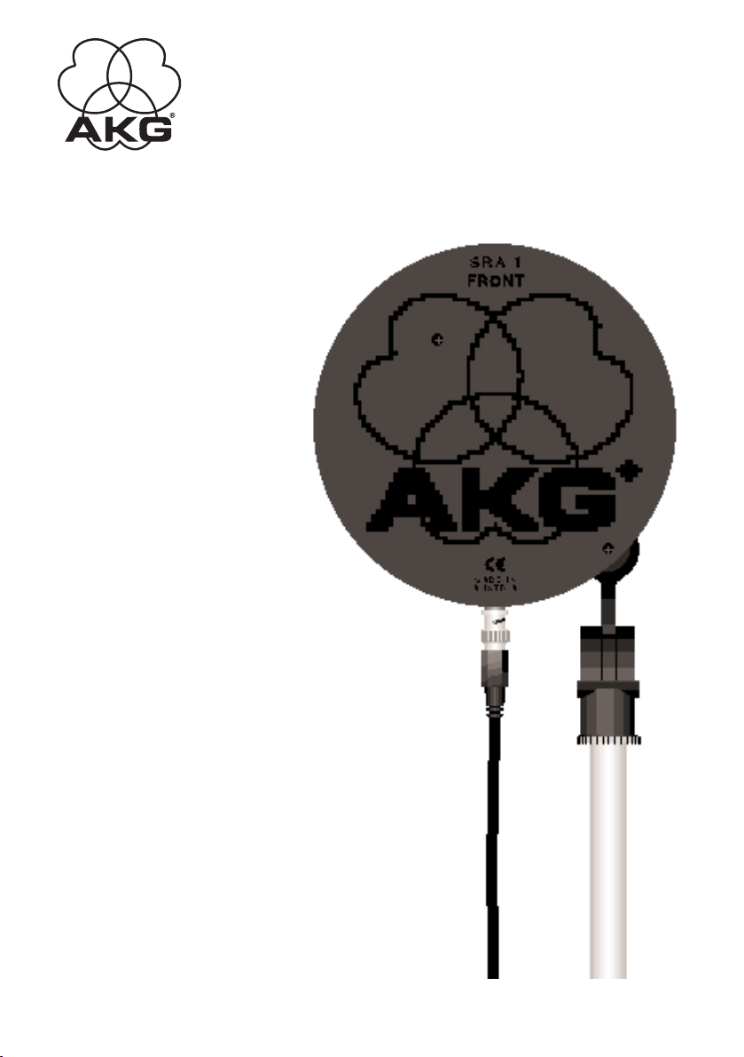
Die SRA 1 ist eine abgesetzte UHF-Antenne mit hypernierenförmiger Richtcharakteristik, die Sie sowohl als Sendeantenne
für das In-Ear Monitor System IVM1 wie auch als Empfangsantenne für die drahtlosen Mikrofonanlagen WMS 81 und
WMS 300 einsetzen können. Die SRA 1 arbeitet auch nahe an
Boden oder Decke (≥15 cm) einwandfrei.
Für Drahtlosanlagen, die im VHF-Bereich arbeiten, können Sie
die SRA 1 NICHT einsetzen.
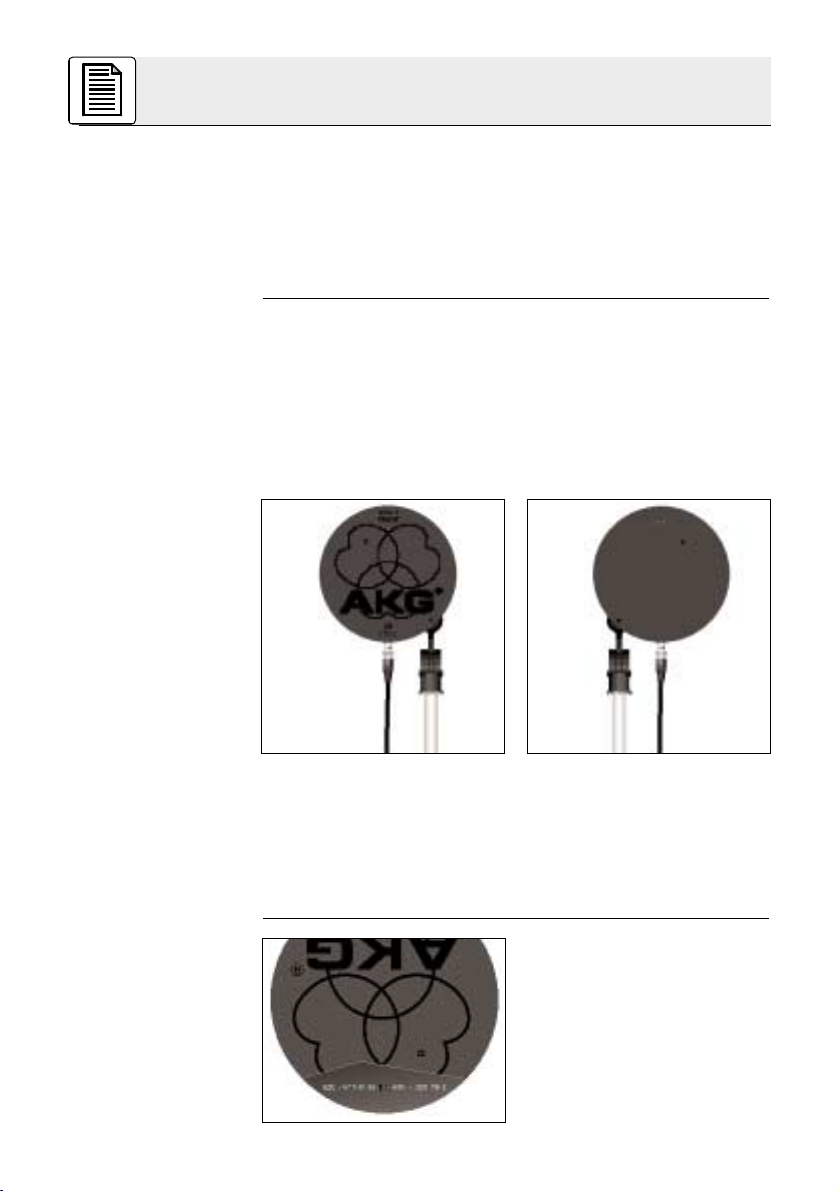
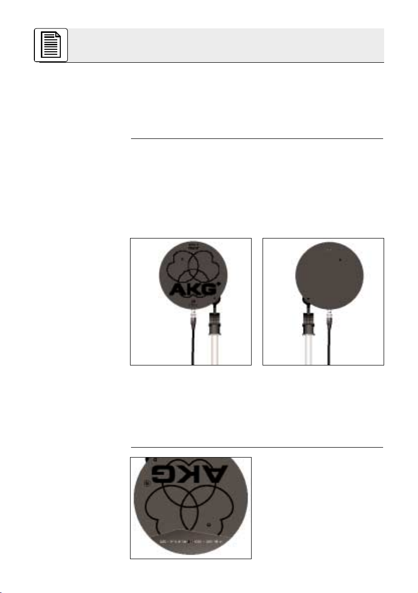
Abb. 1: Vorderansicht Abb.2: Rückansicht
Durch die spezielle Konstruktion der Antenne ergibt sich eine
maximale Signalverstärkung um ca. 6 dB (= 4-fache
Sendeleistung) in der Hauptabstrahlrichtung. Wenn Sie die
SRA 1 als Sendeantenne einsetzen, achten Sie darauf,
dass die gesamte abgestrahlte Leistung den im
Einsatzland zulässigen Höchstwert nicht übersteigt.
An der Innenseite der hinteren
Antennenscheibe befindet sich
ein Schiebeschalter, mit dem
Sie die Antenne an den
Frequenzbereich des angeschlossenen Senders oder
Empfängers anpassen können.
Der Schalter hat zwei
Stellungen:
1 Beschreibung
2
Page 3
1.4 Richtwirkung
1.5 Mitgeliefertes
Zubehör
1.6 Empfohlenes
Zubehör
Rechts: 680 - 820 MHz (Werkseinstellung)
Links: 820 - 945 MHz
Zum Anschluss des Antennenkabels (optional) dient eine BNCBuchse an der Innenseite der vorderen Antennenscheibe.
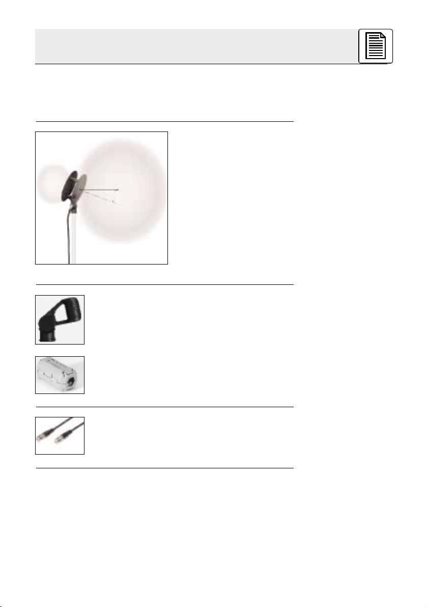
Die Antenne besitzt eine je
nach Abstand von Boden,
Wand oder Decke um 5° bis
20° nach oben gerichtete,
hypernierenförmige
Richtcharakteristik. Diese
Richtcharakteristik ist im
Sende- und Empfangsbetrieb
identisch und vergrößert die
”Reichweite” der Antenne.
Die Hauptabstrahlrichtung
(-empfangsrichtung) liegt vor
der Vorderseite der Antenne.
Abb. 4: Hypernierenförmige Richtcharakteristik.
Stativanschluss SA 40 zur Befestigung der
Antenne an einem Mikrofonstativ mit 3/8”- oder
5/8”-Gewinde.
Ferritkern zum Anklemmen am Antennenkabel
Antennenkabel (RG 58) MK A 5, MK A 10, MK A 20
(Hinweis: Zum Anschließen der Antenne an den
Sender des In-Ear Monitoring Systems IVM 1 eignet sich nur das Antennenkabel MK A 5.)
1 Beschreibung
3
5° - 20°
Page 4
Anm.:
2.1 Antenne aufststellen
Montage an der
Decke:
Wichtig!
Die folgenden Hinweise zum Aufstellen und Ausrichten der
Antenne (Kapitel 2.1 und 2.2) gelten sowohl für den Betrieb als
Sendeantenne wie auch für den Betrieb als Empfangsantenne.
1. Überprüfen Sie, ob der Trägerfrequenzbereich Ihrer(Ihres)
Sender(s) bzw. Empfänger(s) mit dem an der Antenne eingestellten Frequenzbereich übereinstimmt.
Ist dies nicht der Fall, stellen Sie den Frequenzbereichsumschalter an der Antenne auf den anderen Frequenzbereich um.
2. Befestigen Sie die Antenne mit dem mitgelieferten
Stativanschluss SA 40 so auf einem Mikrofonstativ, dass die
Anschlussbuchse senkrecht nach unten zeigt.
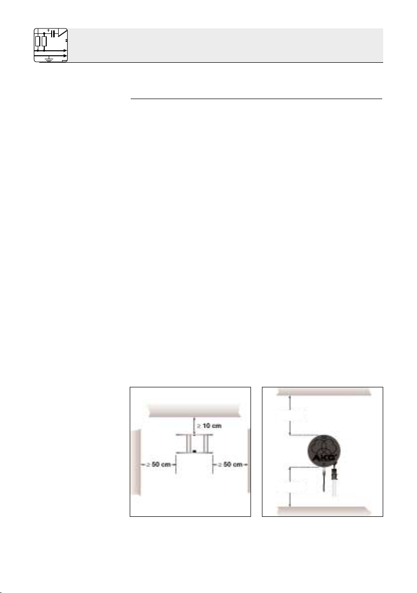
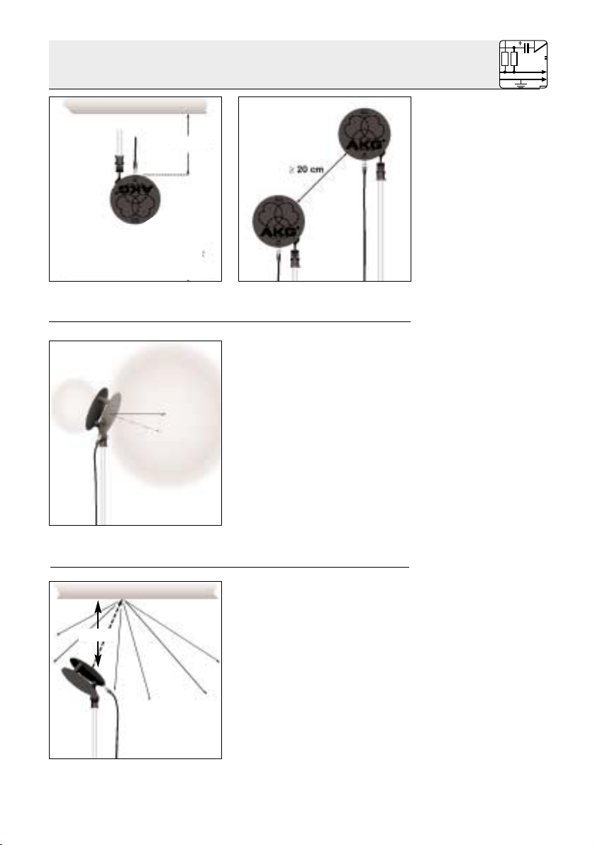
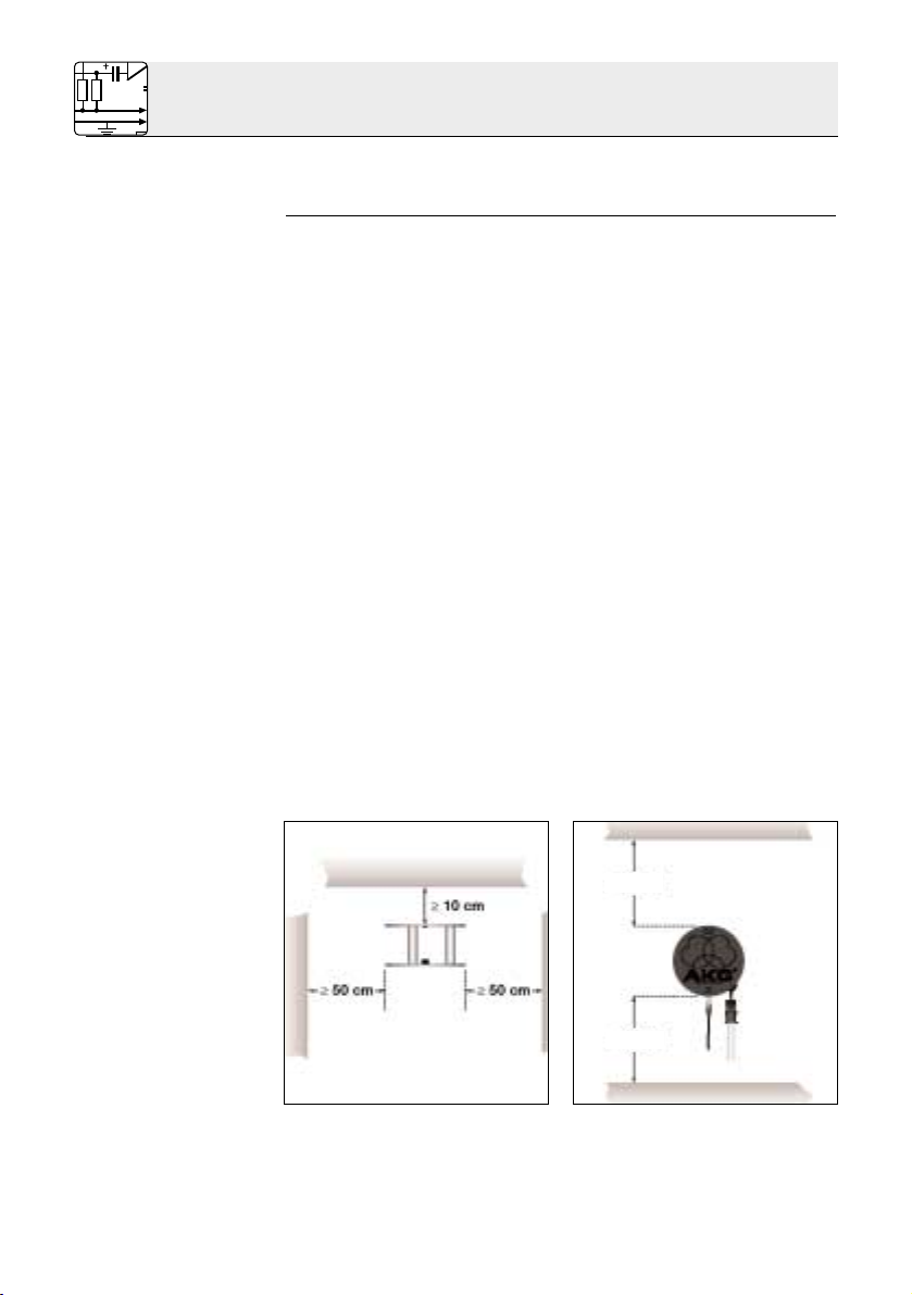
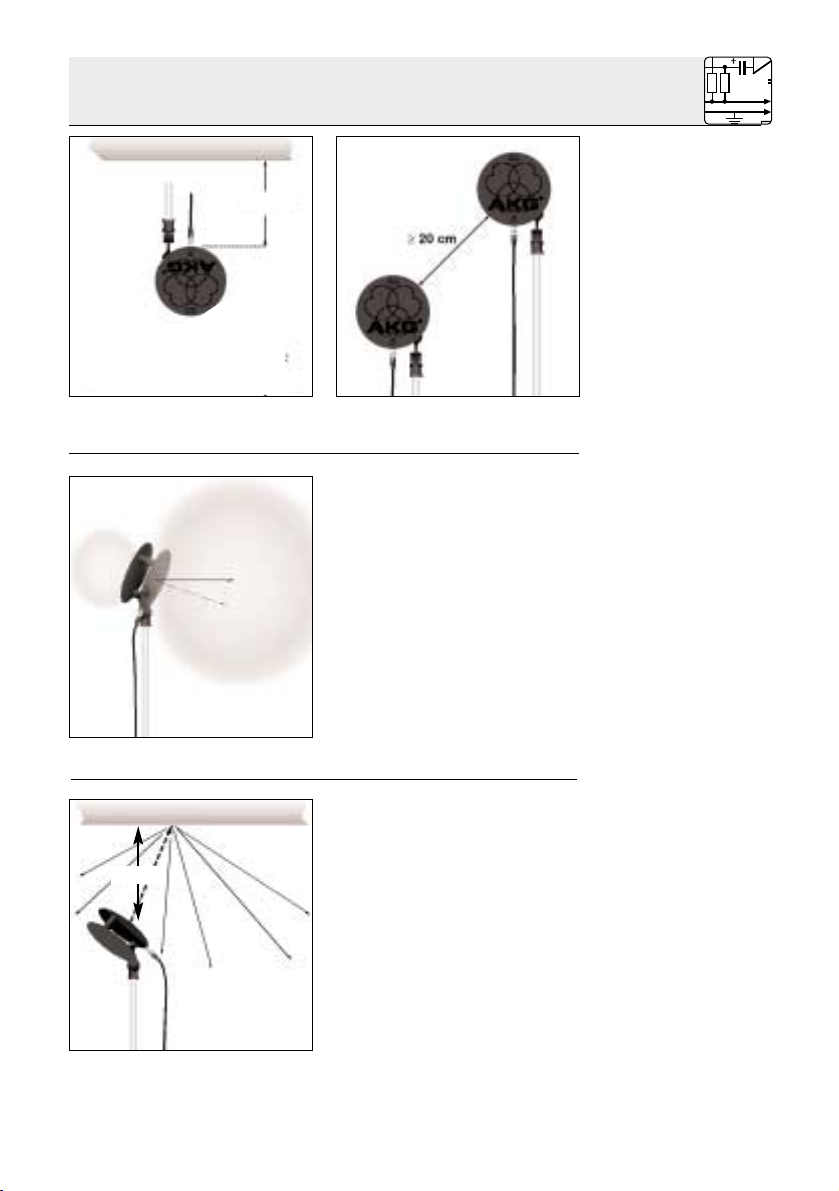
3. Stellen Sie die Antenne wie in Abb. 5 gezeigt mindestens
10 cm vor bzw. in einem seitlichen Abstand von mindestens
50 cm von Wänden oder anderen ebenen Flächen bzw.
Metallgittern oder Metallgerüsten auf.
4. Achten Sie darauf, dass die Antenne mindestens 15 cm vom
Boden bzw. 50 cm (bei Kabelzuführung von oben 15 cm) von
der Decke entfernt ist (Abb. 6 und 7).
5. Wenn Sie zwei Antennen SRA 1 nebeneinander aufstellen
(z.B. für Diversity-Empfang), achten Sie darauf, dass diese
mindestens 20 cm voneinander entfernt sind (Abb. 8).
6. Wenn die Decke hoch genug ist, können Sie mit einer einzigen an der Decke montierten Antenne den gesamten
Aktionsbereich versorgen, indem Sie die Antenne nach
unten richten.
Achten Sie darauf, die Antenne mindestens 10 cm unterhalb
der Decke zu befestigen (s. Abb. 5).
Verwenden Sie ausschließlich Aufhängevorrichtungen aus
isolierendem Material.
2 Aufstellung und Anschluss
4
≥50 cm
≥15 cm
Abb. 5: Mindestabstände von
ebenen Flächen
Abb. 6: Mindestabstand von
Boden und Decke
Page 5
2.2 Antenne ausrichten
2.2.1 Antenne
ausrichten in kleinen Räumen
1. Richten Sie die Antenne
wie einen Scheinwerfer auf
die Mitte des Aktionsbereichs (der Bühne) aus.
2. Die Hauptachse des
Sende- bzw. Empfangsbereichs der Antenne ist
konstruktionsbedingt um
5° bis 20° nach oben
gerichtet.
Lassen Sie die Antenne
daher um 5° bis 20° tiefer
zeigen als die direkte Linie
zum Aktionsbereich (siehe
Abb. 9).
Sie können die Richtantenne
SRA 1 auch in kleinen Räumen
bzw. auf kleinen Bühnen, wo
die Antenne weniger als 10 m
vom Aktionsbereich entfernt ist,
einsetzen.
Richten Sie die Antenne wie in
Abb. 10 gezeigt (ähnlich einer
indirekten Beleuchtung) auf die
Decke aus. Die Decke wirkt
dabei als Reflektor und verteilt
das gerichtete Sendesignal
über den gesamten Raum.
Im Empfangsbetrieb kann die
Antenne so auch Signale aus
2 Aufstellung und Anschluss
5
Abb. 7: Mindestabstand von
der Decke
Abb. 8: Mindestabstand
zwischen zwei Antennen
≥15 cm
5° - 20°
Abb. 9: Richtcharakteristik
der Antenne
Abb. 10: ”Indirekte(r)”
Abstrahlung/Empfang
≥15 cm
Page 6
2.3 Antenne
anschließen
Wichtig!
Wichtig!
Abb. 11: Position
des Ferritkerns am
Kabel.
Wichtig!
SRA 1 als
Sendeantenne:
SRA 1 als
Empfangsantenne:
jenen Ecken des Aktionsbereichs empfangen, die ausserhalb
des eigentlichen Empfangsbereichs der Antenne liegen.
Die Richtantenne SRA 1 besitzt keine aktiven Schaltkreise und
benötigt daher keine Speisespannung. Sie ist jedoch so ausgelegt, dass Sie sie problemlos auch an Anschlüssen mit Speisung
für Antennenverstärker (z.B. PS 81) betreiben können.
Wenn Sie die Antenne an den Sender SST 1 des In-Ear
Monitor Systems IVM 1 anschließen wollen, verwenden Sie
dazu nur das optionale Antennenkabel MK A 5. Bei längeren Kabeln würde die höhere Kabeldämpfung die
Sendeleistung stark schwächen.
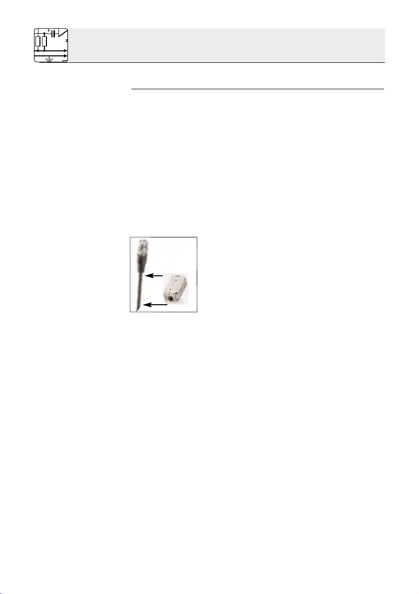
1. Verwenden Sie ein Antennenkabel mit BNC-Steckern (s.
Kapitel 1.6 Empfohlenes Zubehör).
Klemmen Sie den mitgelieferten Ferritkern
unmittelbar hinter einem der beiden Stecker
an das Kabel an (s. Abb. 11).
Der Ferritkern gewährleistet eine symmetrische Richtcharakteristik der Antenne
und verhindert Intermodulationen bei gleichzeitigem Betrieb mehrerer Antennen.
2. Stecken Sie den Stecker, hinter dem Sie den Ferritkern
angeklemmt haben, an die BNC-Anschlussbuchse an der
vorderen Antennenscheibe an.
Achten Sie darauf, dass das Antennenkabel auf einer Länge
von mindestens 20 cm (= Durchmesser der Antenne) senkrecht nach unten hängt (s. a. Abb. 1). Andernfalls würde sich
die Richtcharakteristik der Antenne verändern.
3a. Stecken Sie das andere Ende des Antennenkabels an den
Antennenausgang des Senders SST 1 an. Lesen Sie in der
Bedienungsanleitung des In-Ear Monitor Systems IVM 1
nach.
3b. Stecken Sie das andere Ende des Antennenkabels an den
Antenneneingang Ihres Empfängers oder Power-Splitters an.
Sie können die Antenne an folgende UHF-Geräte anschließen: Empfänger SR 300 und SR 81, Power-Splitter PS 81.
Lesen Sie in der Bedienungsanleitung des jeweiligen
Gerätes nach.
2 Aufstellung und Anschluss
6
Page 7

Gewinn: typ. 5,6 dB (760 MHz)
Rückdämpfung (180°): min. 13 dB
Seitendämpfung (90° ... 110°): ca. 25 dB
Öffnungswinkel: 70°
Frequenzbereich (6 dB): 680 ... 945 MHz
Abmessungen: 152 mm ø, 65 mm tief
Gewicht: 180 g netto, 470 g brutto
3 Technische Daten
7
Page 8
1.1 Introduction
1.2 Operating
Principle
Important Note:
1.3 Frequency
Range Selector
and Connector
Fig. 3: Frequency
Range Selector
Thank you for purchasing a product from AKG. This Manual
contains important information on setting up and operating the
equipment. Please take a few minutes to read the instructions
below carefully before operating the equipment. Please
keep the manual for future reference. Have fun and remember
that AKG equipment has been designed to support your
creativity!
The SRA 1 is a remote UHF antenna with a hypercardioid polar
pattern. You can use the SRA 1 either as a transmitting antenna
with the IVM 1 In-ear Monitor System or as a receiving antenna
with the WMS 81 and WMS 300 wireless microphone systems
from AKG. The SRA 1 will even operate perfectly as close to the
floor or ceiling as 15 cm (6 in.).
Note that the SRA 1 will NOT function with VHF wireless
systems.
Fig. 1: Front view Fig. 2: Rear view
The specific design of the antenna provides a maximum onaxis gain of approximately 6 dB which is equivalent to four
times the transmitter radiated power. If you use the SRA 1 in
transmitting mode, check that the total radiated power
of your system will not exceed the maximum level permitted at the location where you use the system.
A slide switch on the inside of
the rear disk of the antenna lets
you match the antenna to the
frequency range of the transmitter or receiver with which
you use the antenna.
The Frequency Range Selector
provides two positions:
1 Description
8
Page 9

1.4 Polar Pattern
1.5 Standard
Accessories
1.6 Optional
Accessories
Right: 680 to 820 MHz (factory preset)
Left: 820 to 945 MHz
The antenna provides a BNC connector on the inside of the
front disk for connecting a BNC antenna cable (optional).
The antenna has a hypercardioid polar pattern that points
5° to 20° up, depending on
the antenna’s distance from
the floor, wall, or ceiling. The
polar pattern is identical in
transmitting and receiving
modes and increases the
“reach” of the antenna.
The main lobe of the hypercardioid pattern is located in
front of the front disk.
Fig. 4: Hypercardioid polar pattern.
SA 40 stand adapter for mounting the antenna on
a microphone stand with a 3/8” or 5/8” thread.
Ferrite core for fixing on the antenna cable.
MK A 5, MK A 10, MK A 20 antenna cables (RG 58)
(Note: To connect the antenna to the transmitter of
the IVM 1 In-ear Monitor System, use the MK A 5
only.)
1 Description
9
5° - 20°
Page 10
Note:
2.1 Setting Up
Mounting the
antenna on the
ceiling:
Important:
The following hints on setting up and aligning the antenna (sections 2.1 and 2.2) apply to both transmitting and receiving
modes.
1. Check that the carrier frequency range of your transmitter(s) or receiver(s) matches the frequency range set on
the antenna. If it does not, set the Frequency Range Selector
on the antenna to its alternative position.
2. Use the supplied SA 40 stand adapter to mount the antenna
on a microphone stand making sure that the connector
points straight down.
3. Place the antenna at least 10 cm (4 in.) in front of and at a
minimum lateral distance of 50 cm (20 in.) from any walls or
other plane surfaces, metal grids, or metal scaffolding as
shown in fig. 5.
4. Referring to figs. 6 and 7, make sure the antenna will be at
least 15 cm (6 in.) above the floor or 50 cm (20 in.) from the
ceiling (or 15 cm (6 in.) if you route the cable to the antenna
from above).
5. If you set up two SRA 1 antennas side by side (e.g., for
diversity reception), check that the two antennas are spaced
at least 20 cm (8 in.) apart (see fig. 8).
6. If the ceiling is high enough you can cover the entire performance area by mounting a single antenna on the ceiling and
pointing it down.
Make sure to fix the antenna at least 10 cm (4 in.) below the
ceiling (see fig. 5).
Use suspension fixtures made of insulating materials
only.
2 Setting Up and Connecting
10
≥50 cm
≥15 cm
Fig. 5: Minimum distances
from plane surfaces.
Fig. 6: Minimum distances
from floor and ceiling.
Page 11
2.2 Aligning the
Antenna
2.2.1 Aligning the
Antenna in Small
Rooms
1. Aim the antenna like a spotlight at the center of the performance area (stage).
2. Due to the design of the
antenna, the main axis of its
transmitting or receiving
pattern points 5° to 20° up.
Therefore, aim the antenna
5° to 20° lower than the
direct line of sight to the performance area (see fig. 9).
You may also use the SRA 1
directional antenna in small
rooms or on small stages where
the antenna will be less than
10 m (33 ft.) away from the
performance area.
Referring to fig. 10, aim the
antenna at the ceiling (similar to
indirect lighting). The ceiling will
act as a reflector and distribute
the directional signal throughout the room.
In receiving mode, the antenna
will receive signal even from
spots within the performance
2 Setting Up and Connecting
11
Fig. 7: Minimum distance
from the ceiling.
Fig. 8: Minimum distance
between two antennas.
≥15 cm
5° - 20°
Fig. 9: Antenna polar pattern.
Fig. 10: “Indirect” radiation/
reception.
≥15 cm
Page 12

2.3 Connecting
the Antenna
Important!
Important!
Fig. 11: Position of
the ferrite core on
the cable.
Important!
Transmitting
Mode:
Receiving Mode:
area that would otherwise be outside the antenna’s receiving
angle.
The SRA 1 directional antenna uses no active circuitry and therefore requires no power supply. However, its circuitry has been
designed to “neutralize” supply voltages so you can connect
the SRA 1 even to an antenna input or output that provides a
supply voltage for a booster (e.g., PS 81).
To connect the antenna to the SST 1 transmitter of the IVM 1
In-ear Monitor System, use the optional MK A 5 antenna
cable only. Longer cables have a higher attenuation that would
reduce the radiated power considerably.
1. Use an antenna cable with BNC connectors. (Refer to section 1.6 Optional Accessories.)
Fix the supplied ferrite core to the cable
immediately behind one of the two connectors (see fig. 11).
The ferrite core keeps the antenna’s polar
pattern symmetrical and prevents intermodulation when using several antennas at the
same time.
2. Plug the connector behind which you fixed the ferrite core
into the BNC connector on the front disk of the antenna.
Make sure that at least the first 20 cm (8 in., equivalent to the
antenna diameter) of the antenna cable will hang down vertically (refer to fig. 1). Otherwise the antenna’s polar pattern
would change.
3a. Connect the other end of the antenna cable to the antenna
output of the SST 1 transmitter. Refer to the instruction
manual of the IVM 1 In-ear Monitor System.
3b. Connect the other end of the antenna cable to the antenna
input of your receiver or Power Splitter.
You can connect the antenna to the following UHF equipment: SR 300 and SR 81 receivers, PS 81 Power Splitter.
Refer to the instruction manual of the appropriate equipment.
2 Setting Up and Connecting
12
Page 13

Gain: 5.6 dB typ. (760 MHz)
Front-to-back ratio (180°): 13 dB min.
Off-axis attenuation (90° to 110°): approx. 25 dB
Coverage angle: 70°
Frequency range (6 dB): 680 to 945 MHz
Size: diameter:152 mm (5.98 in.)
depth: 65 mm (2.5 in.)
Net/shipping weight: 180g/470 g (6.4/16.6 oz.)
3 Specifications
13
Page 14

1.1 Introduction
1.2 Fonctionnement
Remarque
importante!
1.3 Commutateur
de gamme de fré-
quence et prise
de raccordement
Fig. 3: Commutateur
de gamme de
fréquence
Nous vous remercions d’avoir choisi un produit AKG. Le présent mode d’emploi contient des indications importantes pour
l’installation et l’utilisation de votre antenne. Accordez-vous
quelques minutes pour lire ces instructions avant de mettre
votre antenne en service. Conservez soigneusement ce
mode d’emploi pour pouvoir le consulter au moment où vous
en aurez besoin. Nous vous souhaitons beaucoup de satisfaction et de succès avec cette antenne.
L’antenne directive SRA 1 est une antenne UHF externe à
caractéristique hypercardioïde, que vous pouvez utiliser aussi
bien comme antenne émettrice pour le système de monitoring
à oreillette IVM 1 que comme antenne réceptrice pour les
systèmes de microphones sans fil WMS 81 et WMS 300.
L’antenne SRA 1 donne par ailleurs des résultats tout aussi
satisfaisants à proximité du sol ou du plafond (≥15 cm).
L’antenne SRA 1 n’est pas faite pour les systèmes sans fil fonctionnant dans la bande VHF.
Fig. 1: L’antenne vue de devant Fig. 2: L’antenne vue de derrière
La construction de l’antenne donne une amplification maximale des signaux de 6 dB environ (= le quadruple de la puissance
d’émission) dans le sens de rayonnement principal. Si vous utilisez la SRA 1 en tant qu’antenne émettrice, veillez bien à
ce que la puissance de rayonnement totale ne dépasse
pas la valeur maximum autorisée dans le pays concerné.
Vous trouverez sur la face interne du disque arrière un curseur
à l’aide duquel vous pourrez
adapter l’antenne à la plage de
fréquence de l’émetteur ou du
récepteur auquel elle est raccordée. Vous avez le choix
entre deux positions :
1 Description
14
Page 15

1.4 Directivité
1.5 Accessoires
fournis
1.6 Accessoires
recommandés
Curseur à droite : 680 - 820 MHz (réglage usine)
Curseur à gauche : 820 - 945 MHz
La prise BNC sur la face intérieure du disque avant sert à raccorder le câble d’antenne (optionnel).
L’antenne a une caractéristique de directivité hypercardioïde orientée vers le haut,
correspondant à un angle de
5° à 20° suivant sa distance
au sol, au mur ou au plafond.
La directivité est la même
pour l’émission et pour la
réception ; elle amplifie la
« portée » de l’antenne.
La direction principale de diffusion/de réception est située
en avant de l’antenne.
Fig. 4 : Caractéristique de directivité hypercardioïde
Elément-raccord SA 40 pour la fixation de l’antenne sur un statif de microphone avec pas de 3/8”
ou 5/8”
Tore de ferrite pour fixation au câble d’antenne
Câble d’antenne (RG 58) MK A 5, MK A 10,
MK A 20
(N.B.: Le câble d’antenne MK A 5 est le seul pouvant être utilisé pour raccorder l’antenne au système de monitoring à oreillette IVM 1)
1 Description
15
5° - 20°
Page 16

N.B. :
2.1 Installation de
l’antenne
Montage au
plafond:
Remarque
importante!
Les instructions ci-dessous pour l’installation et l’orientation de
l’antenne (Points 2.1 et 2.2) valent pour l’utilisation aussi bien
en tant qu’antenne émettrice qu’en tant qu’antenne réceptrice.
1. Assurez-vous que la gamme de fréquences porteuses
de votre (vos) émetteur(s) ou récepteur(s) est bien la même
que celle sur laquelle est réglée l’antenne. Si ce n’est
pas le cas, changez en conséquence la position du commutateur de plage de fréquence de votre antenne.
2. Fixez l’antenne à l’aide de l’élément-raccord SA 40 sur un
statif de microphone en veillant à ce que la prise de raccordement se trouve à la verticale, orientée vers le bas.
3. Placez l’antenne comme indiqué à la Fig. 5, la distance aux
murs, parois, grilles métalliques ou échaffaudages de métal
devant être au minimum de 10 cm sur l’arrière et 50 cm
latéralement.
4. Veillez à ce que l’antenne se trouve à une distance minimum
de 15 cm du sol ou 50 cm du plafond (15 cm si le câble arrive par le haut). Cf. Fig. 6 et 7.
5. Si vous placez deux antennes SRA 1 l’une à côté de l’autre
(p.ex. pour la réception Diversity) veillez à ce qu’elles se
trouvent à au moins 20 cm l’une de l’autre (Fig. 8).
6. Si le plafond est suffisamment haut, vous pourrez couvrir la
totalité du rayon d’action avec une seule antenne montée au
plafond et dirigée vers le bas.
L’antenne doit toutefois être fixée à 10 cm au moins du plafond (Cf. Fig. 5).
Pour la suspension, utilisez exclusivement des dispositifs en
matériau isolant.
2 Installation et raccordement
16
≥50 cm
≥15 cm
Fig. 5 : Distance minimum
d’une surface plane
Fig. 6 : Distance minimum du
sol et du plafond
Page 17

2.2 Orientation de
l’antenne
2.2.1 Orientation
de l’antenne dans
une salle exiguë
1. Orientez l’antenne comme
un projecteur sur le centre
du champ d’action (de la
scène).
2. L’axe principal de la zone de
réception ou d’émission de
l’antenne correspond à un
angle de 5° à 20° dirigé par
construction vers le haut.
Orientez donc l’antenne de
5° à 20° vers le bas par rapport à la ligne directe avec le
champ d’action (Fig. 9).
Vous pouvez également utiliser
l’antenne directive SRA 1 dans
une salle exiguë ou sur une
petite scène où elle se trouvera
à moins de 10 m du champ
d’action. Dans ce cas, orientez
l’antenne vers le plafond
comme indiqué à la Fig. 10
(comme vous le feriez pour un
éclairage indirect). Le plafond
joue alors le rôle de réflecteur et
diffuse le signal émis dans toute
la salle.
Pour la réception, l’antenne
ainsi montée peut recevoir des
2 Installation et raccordement
17
Fig. 7 : Distance minimum du
plafond
Fig. 8 : Distance minimum
entre deux antennes
≥15 cm
5° - 20°
Fig. 9 : Caractéristique de
directivité de l’antenne
Fig. 10 : Emission/réception
“indirecte”
≥15 cm
Page 18

2.3 Raccordement
de l’antenne
Remarque
importante!
Remarque
importante !
Fig. 11 : Position du
tore de ferrite sur le
câble
Remarque
importante!
SRA 1 utilisée
comme antenne
émettrice:
SRA 1 utilisée
comme antenne
réceptrice:
signaux venant des coins du champ d’action situés en dehors
de la zone de réception de l’antenne proprement dite.
L’antenne directive SRA 1 ne possède pas de circuits électroniques actifs, elle n’a donc pas besoin d’alimentation. Elle est
cependant conçue de manière à pouvoir être connectée sans
problème sur une embase avec alimentation pour amplificateur
d’antenne (p.ex. PS 81).
Si vous souhaitez raccorder l’antenne à l’émetteur SST 1 du
système de monitoring à oreillette IVM 1, vous devrez impérativement utiliser le câble d’antenne optionnel MK A 5. Avec un
câble plus long, l’atténutation propre au câble réduirait considérablement la puissance d’émission.
1. Utilisez un câble d’antenne à connecteurs BNC (Cf. point 1.6
Accessoires recommandés).
Fixez le tore de ferrite, fourni avec l’antenne,
sur le câble, immédiatement derrière un des
deux connecteurs (Cf. Fig. 11).
Le tore de ferrite garantit une caractéristique
de directivité symétrique et évite les intermodulations lorsqu’on utilise simultanément plu-
sieurs antennes.
2. Mettez le connecteur derrière lequel vous avez fixé le tore de
ferrite dans la prise BNC du disque d’antenne avant.
Le câble d’antenne doit pendre à la verticale sur une longueur de 20 cm au moins (= diamètre de l’antenne), comme
on le voit à la Fig. 1. Sinon, la caractéristique de directivité
de l’antenne se trouverait modifiée.
3a. Connectez l’autre extrémité du câble d’antenne sur la sor-
tie de l’émetteur SST 1. Reportez-vous à cet effet au mode
d’emploi du système de monitoring à oreillette IVM 1.
3b. Connectez l’autre extrémité du câble d’antenne sur l’entrée
d’antenne de votre récepteur ou de votre système de distribution d’antenne.
Vous pouvez raccorder l’antenne aux appareils UHF suivants: récepteurs SR 300 et SR 81, système de distribution
d’antenne PS 81. Veuillez vous reporter aux modes d’emploi
correspondants.
2 Installation et raccordement
18
Page 19

Gain : typ. 5,6 dB (760 MHz)
Atténuation inverse (180°) : 13 dB au minimum
Atténuation latérale (90°…110°) : 25 dB env.
Ouverture : 70°
Gamme de fréquence (6 dB) : 680…945 MHz
Dimensions : Ø 152 mm
profondeur 65 mm
3 Caractéristiques techniques
19
Page 20

1.1 Introduzione
1.2 Modo di
funzionamento
Avvertenza
importante:
1.3 Commutatore
frequenze e presa
di collegamento
Fig. 3: Commutatore
di frequenza
Grazie di aver acquistato un prodotto AKG. Le presenti istruzioni per l’uso contengono importanti avvertenze per l’installazione e l’esercizio dell’apparecchio. Prendetevi alcuni minuti di
tempo per leggere le istruzioni prima di usare l’apparecchio.
Conservate le istruzioni per l’uso con cura per poterle consultare in qualsiasi momento. Vi auguriamo buon divertimento e
buon successo!
La SRA 1 è un’antenna UHF staccata con direttività ipercardioide; potrà essere usata sia come antenna di trasmissione per il
sistema In-Ear Monitor System IVM 1 che come antenna di
ricezione per gli impianti microfonici senza filo WMS 81 e
WMS 300. La SRA 1 funziona senza problemi anche se posizionata vicino a pavimenti o soffitti (≥15 cm).
La SRA 1 NON potrà venir usata per impianti senza filo che
lavorano nella gamma VHF!
Fig.1: Lato anteriore Fig.2: Lato posteriore
Grazie alla costruzione speciale dell’antenna risulta un‘amplificazione massima del segnale di 6 dB circa (= quadrupla potenza di trasmissione) nella direzione di irradizione principale. Se
usate la SRA 1 come antenna di trasmissione, fate atten-
zione che l’intera potenza d’irradiazione non superi il
valore massimo ammesso nel paese d’utilizzo.
Sul lato interno del disco
posteriore dell’antenna si trova
un interuttore a scorrimento
con il quale potete adeguare
l’antenna alla gamma di frequenze del trasmettitore o del
ricevitore collegato.
L’interruttore ha due posizioni:
1 Descrizione
20
Page 21

1.4 Direttività
1.5 Accessori in
dotazione
1.6 Accessori
raccomandati
Destra: 680 - 820 MHz (regolazione in fabbrica)
Sinistra: 820 - 945 MHz
Per collegare il cavo d’antenna (opzionale), è a disposizione
una presa BNC disposta sul lato interno del disco anteriore
dell’antenna.
L’antenna è dotata di una
direttività ipercardioide, girata
di 5° - 20° verso l’alto, a
seconda della distanza dal
pavimento, dalla parete o dal
soffitto. Tale direttività è identica sia per l’esercizio di trasmissione che per quello di
ricezione e aumenta la “portata” dell’antenna.
La direzione principale di irradiazione (ricezione) si trova
davanti al lato anteriore
dell’antenna.
Fig.4: Direttività ipercardioide
Collegamento per supporto SA 40 per fissare l’antenna ad un supporto microfonico con filettatura
da 3/8” o 5/8”.
Nucleo in ferrite per montaggio sul cavo d’antenna.
Cavi d’antenna (RG 58) MK A 5, MK A 10, MK A 20
(Avvertenza: Per collegare l’antenna al trasmettitore del sistema In-Ear Monitoring System
IVM 1 è adatto solo il cavo d’antenna MK A 5).
1 Descrizione
21
5° - 20°
Page 22

Nota:
2.1 Installazione
dell’antenna
Montaggio sul
soffitto:
Importante!
Le seguenti indicazioni per l’installazione e l’orientamento
dell’antenna (capitoli 2.1 e 2.2) valgono sia per l’utilizzo dell’antenna come antenna di trasmissione che per l’utilizzzo come
antenna di ricezione.
1. Controllate se la gamma delle frequenze portanti del
(dei) vostro(i) trasmettitore(i) risp. ricevitore(i) concorda con
la gamma delle frequenze regolata sull’antenna.
Se questo non è il caso, portate il commutatore delle frequenze disposto sull’antenna in un altra gamma frequenze.
2. Fissate l’antenna per mezzo del collegamento per supporto
SA 40 in dotazione su un supporto microfonico in modo che
la presa di collegamento guardi verticalmente in basso.
3. Installate l’antenna, come indicato nella fig. 5, ad una distanza di almeno 10 cm davanti risp. ad una distanza laterale di
almeno 50 cm da pareti o altre superifci piane, oppure reti o
intelaiature metalliche.
4. Fate attenzione che l’antenna abbia una distanza minima di
15 cm dal pavimento, rispettivamente di 50 cm (se il cavo
arriva dall’alto: 15 cm) dal soffitto (figg. 6 e 7).
5. Se posizionate due antenne SRA 1 una accanto all’altra (p.e.
per ricezione diversity), fate attenzione che la distanza tra le
antenne sia di almeno 20 cm (fig. 8).
6. Se il soffitto è sufficientemente alto, potete coprire l’intero
campo d’azione con un’unica antenna montata sul soffitto
girando l’antenna verso il basso.
Fate attenzione che l’antenna sia fissata ad una distanza di
almeno 10 cm sotto il soffitto (v. fig. 5).
Usate solo dispositivi di fissaggio realizzati in materiale
isolante.
2 Installazione e collegamento
22
≥50 cm
≥15 cm
Fig: 5: Distanza minima da
superfici piane
Fig. 6: Distanza minima da
pavimento e soffitto
Page 23

2.2 Orientamento
dell’antenna
2.2.1
Orientamento
dell’antenna in
spazi piccoli
1. Orientate l’antenna come un
riflettore sul centro del
campo d’azione (del palco).
2. Per ragioni di costruzione,
l’asse principale del campo
di trasmissione, risp. del
campo di ricezione dell’antenna è orientata di 5° fino a
20° verso l’alto.
Fate in modo che l’antenna
sia di 5° fino a 20° più in
basso della linea diretta
verso il campo d’azione
(fig. 9).
Potete usare l’antenna direzionale SRA 1 anche in piccoli
spazi risp. su piccoli palchi
dove l’antenna è posizionata a
meno di 10 m dal campo d’azione.
Orientate l’antenna sul soffitto
come indicato nella fig. 10
(simile ad un’illuminazione indiretta). Il soffitto agisce da riflettore e distribuisce il segnale di
trasmissione direzionale su
tutto lo spazio.
Nell’esercizio di ricezione l’antenna potrà quindi ricevere
anche segnali da quegli angoli
2 Installazione e collegamento
23
Fig. 7: Distanza minima dal
soffitto
Fig. 8: Distanza minima tra le
antenne
≥15 cm
5° - 20°
Fig. 9: Direttività dell’antenna
Fig. 10: Irradiazione/ricezione
“indiretta”
≥15 cm
Page 24

2.3 Collegamento
dell’antenna
Importante!
Importante!
Fig. 11: Posizione
del nucleo in ferrite
sul cavo
Importante!
La SRA 1 come
antenna di
trasmissione:
La SRA 1 come
antenna di
ricezione:
del campo d’azione che si trovano al di fuori del campo di ricezione vero e proprio dell’antenna.
L’antenna direzionale SRA 1 non è dotata di circuiti attivi e non
necessita quindi di alimentazione. È comunque realizzata in
modo tale che potrà essere usata senza problemi anche con
collegamenti che prevedono l’alimentazione per amplificatori
d’antenna (p.e. PS 81).
Se volete collegare l’antenna al trasmettitore SST 1 del sistema In-Ear Monitoring System IVM 1, usate a tale scopo solo
il cavo d’antenna opzionale MK A 5.
Se usate cavi più lunghi, la maggiore attenuazione del cavo
indebolirebbe di molto la potenza di trasmissione.
1. Usate un cavo d’antenna con connettori BNC (v. capitolo 1.6
Accessori raccomandati).
Fissate il nucleo in ferrite (in dotazione) sul
cavo direttamente dietro ad uno dei due connettori (v. fig. 11). Il nucleo in ferrite garantisce la direttività simmetrica dell’antenna evitando intermodulazioni in caso di uso con-
temporaneo di più antenne.
2. Collegate il connettore dietro al quale avete fissato il nucleo
in ferrite alla presa di collegamento BNC disposta sul disco
anteriore dell’antenna.
Fate attenzione che il cavo d’antenna penda verticalmente in
basso per una lunghezza di almeno 20 cm (= diametro
dell’antenna) (v. anche fig. 1). Altrimenti la direttività dell’antenna cambierebbe.
3a. Inserite l’altra estremità del cavo d’antenna nell’uscita d’an-
tenna del trasmettitore SST 1. Consultate al riguardo le istruzioni per l’uso del sistema In-Ear Monitor System IVM 1.
3b. Inserite l’altra estremità del cavo d’antenna nell’ingresso
d’antenna del vostro ricevitore o power-splitter.
Potete collegare l’antenna ai seguenti apparecchi UHF: ricevitori SR 300 e SR 81, power-splitter PS 81. Consultate al
riguardo le istruzioni per l‘uso del rispettivo apparecchio.
2 Installazione e collegamento
24
Page 25

Guadagno: tip. 5,6 dB (760 MHz)
Rapporto fronte-retro (180°): 13 dB min.
Rapporto lato frontale-lato
(90° ... 110°): 25 dB circa
Angolo di apertura: 70°
Gamma di frequenze (6 dB): 680 ... 945 MHz
Dimensioni: diametro 152 mm,
profondità 65 mm
Peso: 180 g netti, 470 g lordi
3 Dati tecnici
25
Page 26

1.1 Introducción
1.2
Funcionamiento
Advertencia:
1.3 Conmutador
de gama de fre-
cuencias y borna
de conexión
Fig.3: Conmutador
de gama de
frecuencias
Muchas gracias por haberse decidido por un producto de la
empresa AKG. En este Modo de empleo encontrará importantes indicaciones para la instalación y el funcionamiento de su
nuevo equipo y le rogamos que se tome unos minutos para
leerlo antes de utilizar el equipo. Sírvase guardar bien este
Modo de empleo para poder consultarlo cuando lo requiera.
¡Que se divierta y que tenga mucho éxito con su nuevo equipo!
La SRA 1 es una antena UHF espaciada con característica
direccional hipercardioide. Se puede utilizar como antena emisora para el sistema In-Ear Monitor System IVM 1 y asimismo
como antena receptora para los sistemas microfónicos inalámbricos WMS 81 y WMS 300. La SRA 1 funciona también impecablemente cerca del suelo o del techo (* 15 cm), pero NO se
puede utilizar para equipos inalámbricos que funcionan en el
ámbito VHF.
Fig.1: Vista frontal Fig.2: Vista posterior
Debido a la construcción especial de la antena se produce una
amplificación de la señal en aprox. 6 dB (= potencia de emisión
cuádruple) en la dirección de radiación principal. Si se utiliza la
SRA 1 como antena emisora, hay que cuidar que la
potencia irradiada no sobrepase el valor superior permitido en el país de uso.
En la cara interior del disco
posterior de la antena se
encuentra un conmutador corredizo con el cual se puede
adaptar la antena a la gama de
frecuencias del emisor o receptor conectados.
El conmutador tiene dos posiciones:
1 Descripción
26
Page 27

1.4 Directividad
1.5 Accesorios
incluidos
1.6 Accesorios
recomendados
Derecha: 680 - 820 MHz (ajustada en fábrica)
Izquierda: 820 - 945 MHz
En la cara interior del disco delantero de la antena hay una
borna BNC que se puede utilizar para la conexión al cable de
antena (opcional).
La antena tiene una característica direccional hipercardioide dirigida hacia arriba en
5° a 20°, dependiendo de la
distancia al suelo, muralla o
techo. Esta característica
direccional es la misma, tanto
para la emisión como para la
recepción y aumenta el
"alcance" de la antena.
La dirección principal del haz
(dirección principal de recepción) se encuentra delante de
la cara anterior de la antena.
Fig.4: Característica direccional
hipercardioide
Adaptador de soporte SA 40 para la fijación de la
antena en un soporte de micrófono con rosca de
3/8“ ó 5/8“.
Núcleo de ferrita para fijar al cable de antena
Cables de antena (RG 58) MK A 5, MK A 10,
MK A 20
(Nota: Para la conexión de la antena al emisor del
In-Ear Monitoring System IVM 1 sólo debe utilizarse el cable MK A 5.)
1 Descripción
27
5° - 20°
Page 28

Nota:
2.1 Instalación de
la antena
Montaje en el
techo:
¡Importante!
Las siguientes indicaciones para la instalación y la orientación
de la antena (Capítulos 2.1 y 2.2) rigen para su uso como
antena emisora y antena receptora.
1. Verifique que la gama de frecuencia portadora de su(s)
emisor(es) o receptor(es) concuerde con la gama de
frecuencias ajustada en la antena.
Si no es el caso, cambie el conmutador de gama de frecuencias de la antena a la otra gama de frecuencias.
2. Fije la antena, con el adaptador de soporte SA 40 incluido,
de tal forma en un soporte de micrófono, que la borna de
conexión indique verticalmente hacia abajo.
3. Tal como se indica en la Fig.5, coloque la antena a una
distancia de por lo menos 10 cm delante o 50 cm al lado de
murallas u otras superficies planas o de rejas o armazones
metálicos.
4. Verifique que la antena se encuentre a por lo menos 15 cm
del suelo o a 50 cm del techo (si el cable llega desde arriba,
a 15 cm) (Figs. 6 y 7).
5. Si instala dos antenas SRA 1 una al lado de la otra, (p.ej.
para la recepción en diversidad), verifique que estén a por lo
menos 20 cm de distancia (Fig.8).
6. Si el techo es suficientemente alto, con una sola antena
montada en el techo y dirigida hacia abajo se puede abarcar
todo el campo de acción.
La antena debe estar fijada a por lo menos 10 cm debajo del
techo (véase Fig.5).
Utilice exclusivamente dispositivos de suspensión de
material aislante.
2 Instalación y conexión
28
≥50 cm
≥15 cm
Fig.5: Distancias mínimas de
superficies planas
Fig.6: Distancia mínima del
suelo y del techo
Page 29

2.2 Orientación
de la antena
2.2.1 Orientación
de la antena en
salas pequeñas
1. Oriente la antena, como un
proyector, a la mitad del
campo de acción (del
escenario).
2. Debido a su construcción, el
eje principal de la gama de
transmisión y de recepción,
respectivamente, está dirigido hacia arriba en 5° a 20°.
Por lo tanto, la antena debe
estar inclinada en 5° a 20°
más hacia abajo que la línea
directa al campo de acción
(Fig. 9).
La antena direccional SRA 1 se
puede utilizar también en salas
o escenarios pequeños, donde
ha de estar a menos de 10 m
del campo de acción.
Tal como se indica en la Fig.10,
oriente la antena hacia el techo
(como se hace con iluminación
indirecta). El techo actúa como
reflector, distribuyendo la señal
emisora dirigida por toda la
sala.
En el modo de recepión, la
antena también puede recibir
señales de aquellos rincones
2 Instalación y conexión
29
Fig.7: Distancia mínima del
techo
Fig.8: Distancia mínima entre
2 antenas
≥15 cm
5° - 20°
Fig. 9: Característica direccional de la antena
Fig:10: Emisión/recepción
*indirecta*
≥15 cm
Page 30

2.3 Conexión de
la antena
¡Importante!
¡Importante!
Fig.11: Posición del
núcleo de ferrita al
cable.
¡Importante!
La SRA 1 como
antena emisora:
La SRA 1 como
antena receptora:
del campo de acción que se encuentren fuera del ámbito de
recepción propiamente dicho de la antena.
La antena direccional SRA 1 no dispone de circuitos activos y,
por lo tanto, no necesita tensión de alimentación. Sin embargo,
está construida de tal forma que se la puede utilizar sin problemas en conexiones con alimentación para amplificadores de
antena (p.ej. el PS 81).
Si desea conectar la antena al emisor SST 1 del In-Ear
Monitoring System IVM 1, utilice sólo el cable de antena
opcional MK A 5. Con cables más largos, la atenuación
mayor del cable debilitaría mucho la potencia de transmisión.
1. Utilice un cable de antena con conectores BNC (véase el
Capítulo 1.6 Accesorios recomendados).
Fije el núcleo de ferrita al cable inmediatamente después de uno de los dos conectores
(véase Fig.11). El núcleo de ferrita garantiza
una característica direccional simétrica de la
antena, impidiendo intermodulaciones cuando
se utilizan varias antenas simultáneamente.
2. Enchufe el conector, detrás del cual ha fijado el núcleo de
ferrita, en la borna de conexión BNC del disco de antena
delantero.
Verifique que el cable de la antena esté colgado verticalmente hacia abajo en por lo menos 20 cm (= diámetro de la
antena). De lo contrario, se modificaría la característica
direccional de la antena.
3a. Enchufe el otro extremo del cable de la antena en la salida
de antena del emisor SST 1. Sírvase consultar para ello el
Modo de empleo del In-Ear Monitor System IVM 1.
3b. Enchufe el otro extremo del cable de la antena en la entra-
da de antena de su receptor o divisor de potencia.
La antena se puede conectar a los siguientes aparatos UHF:
Receptor SR 300 y SR 81, Divisor de potencia PS 81.
Sírvase consultar para ello el Modo de empleo del aparato
correspondiente.
2 Instalación y conexión
30
Page 31

Rendimiento: típ. 5,6 dB (760 MHz)
Eficacia direccional (180°): mín. 13 dB
Atenuación lateral (90°...110°): aprox. 25 dB
Angulo de abertura: 70°
Gama de frecuencias (6 dB): 680...945 MHz
Dimensiones: 152 mm de diámetro,
65 mm prof.
Peso: 180 g neto, 470 g bruto
3 Datos técnicos
31
Page 32

1.1 Introdução
1.2 Modo de
funcionamento
Aviso importante:
1.3 Comutador de
banda de
freqüência e
conetor
Fig. 3: Comutador
de banda de
freqüência
Agradecemos a sua preferência por um produto da AKG. Este
manual contém informações importantes quanto à instalação e
a utilização da antena. Antes de utilizar a antena, favor
reserve alguns minutos para ler este manual. Guarde-o bem
para poder consultá-lo sempre. Divirta-se e bom trabalho!
A SRA 1 é uma antena independente do tipo UHF com uma
caraterística direcional hipercardióide que pode ser aplicada
como antena emissora para o sistema In-Ear Monitor IVM 1 e
como antena de recepção para os sistemas de microfones sem
fio WMS 81 e WMS 300. A SRA 1 funciona também perto do
solo ou perto do teto (≥15 cm) sem problemas. A SRA 1 NÃO
pode ser aplicada em sistemas sem fio que funcionam na
banda de freqüências VHF.
Fig. 1: Lado de frente Fig. 2: Lado de trás
Através da construção especial da antena resulta uma amplificação máxima de sinais de aproximadamente 6 dB (= uma
emissão 4 vezes mais forte) na direção principal de emissão.
Se usar a SRA 1 como antena emissora, certifique-se de
que a potência de emissão não ultrapassa o valor máximo permitido no país onde é aplicada.
No lado interno do disco traseiro da antena encontra-se um
comutador em forma de barra
de rolagem com o qual pode
ajustar a antena à banda de freqüência do emissor ou receptor
ligado.
O comutador possui duas
posições:
1 Descrição
32
Page 33

1.4 Caraterística
direcional
1.5 Acessórios
fornecidos na
embalagem
1.6 Acessórios
opcionais
Lado direito: 680 - 820 MHz (ajuste da fábrica)
Lado esquerdo: 820 - 945 MHz
Existe no lado interior do disco dianteiro da antena um conetor
BNC que serve para ligar o cabo de antena (opcional).
A antena possui, dependendo da sua distância do solo,
da parede ou do teto, uma
caraterística direcional em
forma de hipercardióide dirigida 5º a 20º para cima. Esta
caraterística direcional é
idêntica no modo de emissão
e recepção e aumenta o "raio
de ação" da antena. A
direção principal de emissão
(recepção) encontra-se em
posição anterior ao lado
dianteiro da antena.
Fig. 4: Caraterística direcional
em forma de hipercardióide
Adaptador de tripé SA 40 para fixar a antena num
tripé de microfone com rosca de 3/8" ou 5/8".
Núcleo de ferrita para fixar no cabo de antena.
Cabo de antena (RG 58) MK A 5, MK A 10,
MK A 20
(Aviso: Ligue a antena ao emissor do sistema InEar Monitor IVM 1 só com o cabo MK A 5.)
1 Descrição
33
5° - 20°
Page 34

Obs.:
2.1 Montagem da
antena
Montagem no
teto:
Importante!
Os avisos para a montagem e a orientação da antena
(capítulo 2.1 e 2.2) servem para a utilização como antena
emissora e como antena receptora.
1. Certifique-se de que a banda da freqüência portadora
do(s) seu(s) emissor(es) ou receptore(s) corresponde à
banda de freqüência ajustada na antena.
Se isso não for o caso, leve o comutador de freqüência na
antena na posição alternativa.
2. Fixe a antena num tripé de microfone com o adaptador de
tripé SA 40 de maneira que o conetor se encontre no lado de
baixo em posição perpendicular.
3. Posicione a antena a uma distância direta de pelo menos
10 cm ou a uma distância lateral de pelo menos 50 cm de
paredes ou outras superfícies planas, ou de grades e andaimes de metal.
4. Certifique-se de que a antena se encontra a uma distância
de pelo menos 15 cm do solo e de 50 cm (15 cm se o cabo
estiver conduzido de cima) do teto (fig. 6 e 7).
5. Se montar duas antenas SRA 1 uma ao lado da outra, certifique-se de que a distância entre as duas antenas é de
20 cm no mínimo (fig. 8).
6. Se o teto for suficientemente alto, poderá abastecer toda a
área de ação com uma única antena fixada no teto, direcionando a antena para baixo.
É importante fixar a antena 10 cm abaixo do teto (veja fig. 5)
Use dispositivos de montagem feitos só de material
isolante.
2 Montagem e ligação
34
≥50 cm
≥15 cm
Fig. 5: Distância mínima de
superfícies planas
Fig. 6: Distância mínima do
solo e do teto
Page 35

2.2 Direcionar a
antena
2.2.1 Direcionar a
antena em salas
pequenas
1. Direcione a antena para o
meio da área de ação (por
exemplo o palco) como um
farol.
2. O eixo principal da faixa de
recepção e de emissão da
antena, em virtude da construção, é direcionada 5º a
20º para cima.
Por isso direcione a antena
por 5º a 20º mais baixo em
relação à linha direta para a
área de ação (fig. 9).
Pode usar a antena SRA 1 também em salas ou palcos
pequenos onde a antena se
encontra a menos de 10 m da
área de ação.
Direcione a antena para o teto
como indicado na fig. 10 (de
maneira semelhante à iluminação indireta). O teto serve de
refletor e distribui o sinal de
emissão pela sala inteira.
Desta forma, a antena pode
receber sinais dos cantos da
2 Montagem e ligação
35
Fig. 7: Distância mínima do
teto
Fig. 8: Distância mínima entre
duas antenas
≥15 cm
5° - 20°
Fig. 9: Caraterística direcional
da antena
Fig. 10: Emissão/recepção
indireta
≥15 cm
Page 36

2.3 Ligar a antena
Importante!
Importante!
Fig. 11: Posição do
núcleo de ferrita no
cabo
Importante!
Se usar a SRA 1
como antena de
emissão:
Se usar a SRA 1
como antena de
recepção:
área de ação que se encontram fora da própria área de
recepção da antena.
A antena direcional SRA 1 não possui circuitos ativos e por isso
não precisa de corrente de alimentação. No entanto, é concebido de forma que funcione também quando a ligar a uma entrada ou saída de antena com alimentação para um amplificador de antena (por exemplo PS 81).
Se desejar ligar a antena ao emissor SST 1 do sistema In-Ear
Monitor IVM 1, use só o cabo de antena opcional MK A 5.
Se o cabo for mais comprido, a atenuação do cabo poderá
reduzir bastante a potência de emissão.
1. Use um cabo de antena com conetores BNC (veja capítulo
1.6 Acessórios opcionais).
Fixe o núcleo de ferrita fornecido na embalagem ao cabo diretamente atrás de um dos
conetores (veja fig. 11).
O núcleo de ferrita garante uma caraterística
direcional simétrica da antena e impede intermodulações quando aplicar mais antenas ao
mesmo tempo.
2. Ligue o conetor atrás do qual fixou o núcleo de ferrita à
tomada de conexão do disco anterior da antena.
Certifique-se de que o cabo da antena está pendurado em
posição perpendicular a uma distância de pelo menos
20 cm (= diâmetro da antena) (veja também fig. 1). Caso
contrário a caraterística direcional da antena pode alterar.
3a. Ligue a outra extremidade do cabo da antena à saída do
emissor SST 1. Leia o manual do sistema In-Ear Monitor
IVM 1.
3b. Ligue a outra extremidade do cabo da antena à entrada do
seu receptor ou Power Splitter.
Pode ligar a antena aos seguintes aparelhos UHF:
receptores SR 300 e SR 81, Power Splitter PS 81. Leia o
manual do respectivo aparelho.
2 Montagem e ligação
36
Page 37

Ganho: típ. 5,6 dB (760 MHz)
Atenuação traseira (180º): 13 dB mínimo
Atenuação lateral (90º ... 110º): aproximadamente 25 dB
Ângulo de abertura: 70º
Banda de freqüência (6 dB): 680 ... 945 MHz
Dimensões: diâmetro: 152 mm
profundidade: 65 mm
Peso: 180 g líquido, 470 g bruto
3 Dados técnicos
37
Page 38

38
Notizen - Notes - Notes - Note - Notas - Notas
Page 39

39
Notizen - Notes - Notes - Note - Notas - Notas
Page 40

Printed in Austria on recycled paper. 02/00/9100 U 0990
Technische Änderungen vorbehalten. Specifications subject to change without notice. Ces caractéristiques sont susceptibles de modifications.
Ci riserviamo il diritto di effettuare modifiche tecniche. Nos reservamos el derecho de introducir modificaciones técnicas. Especificações sujeitas à mudanças sem aviso prévio.
Mikrofone · Kopfhörer · Drahtlosmikrofone · Drahtloskopfhörer · Kopfsprechgarnituren · Akustische Komponenten
Microphones · Headphones · Wireless Microphones · Wireless Headphones · Headsets · Electroacoustical Components
Microphones · Casques HiFi · Microphones sans fil · Casques sans fil · Micros-casques · Composants acoustiques
Microfoni · Cuffie HiFi · Microfoni senza filo · Cuffie senza filo · Cuffie-microfono · Componenti acustici
Micrófonos · Auriculares · Micrófonos inalámbricos · Auriculares inalámbricos · Auriculares con micrófono · Componentes acústicos
Microfones · Fones de ouvido · Microfones s/fios · Fones de ouvido s/fios · Microfones de Cabeça · Componentes Acústicos
AKG Acoustics GmbH
Lemböckgasse 21–25, P.O.B. 158, A-1230 Vienna/AUSTRIA
Tel: (43 1) 86 654-0*, Fax: (43 1) 86 654-516
Internet: http://www.akg-acoustics.com
AKG Acoustics, Harman Pro GmbH
Bodenseestraße 228, D-81243 München/GERMANY
Tel: (089) 87 16-0, Fax: (089) 87 16-200
e-mail: akg-acoustics@t-online.de
Arbiter Pro Audio
Wilberforce Road, London NW9 6AX/ENGLAND
Tel: (0181) 202 1199, Fax: (0181) 202 7076
AKG ACOUSTICS, U.S.
1449 Donelson Pike, Nashville, TN 37217, U.S.A.
Tel:(615) 360-0499, Fax: (615) 360-0275
Studer Japan Ltd.
2-43-7, Uehara, Shibuya-ku, Tokyo 151-0064/JAPAN
Tel: (813) 3465-2211, Fax: (813) 3465-2214
Erikson Pro Audio
620 McCaffrey, St-Laurent, Quebec, H4T 1N1, CANADA
Tel: (514) 738-3000, Fax: (514) 737-5069
Internet: www.jam-ind.com/eriksonpro
SRA 1
WMS 81 WMS 300
IVM 1
 Loading...