

Page 1
WIRELESS
AKG.WIRELESS
MICROPHONE
SYSTEM
WMS40
microtools
Bedienungshinweise . . . . . . . . . . . . . . . . . . S. 2
Bitte vor Inbetriebnahme des Gerätes lesen!
User Instructions . . . . . . . . . . . . . . . . . . . . p. 10
Please read the manual before using the equipment!
Mode d’emploi . . . . . . . . . . . . . . . . . . . . . . p. 18
Veuillez lire cette notice avant d’utiliser le système!
Istruzioni per l’uso . . . . . . . . . . . . . . . . . . . p. 26
Prima di utilizzare l’apparecchio, leggere il manuale!
Modo de empleo . . . . . . . . . . . . . . . . . . . . p. 34
Antes de utilizar el equipo, sírvase leer el manual!
Instruções de uso . . . . . . . . . . . . . . . . . . . p. 42
S.f.f. leia este manual antes de usar o equipamen
to!
MP40
micropen
Page 2
1 Sicherheit und
Umwelt
1.1 Sicherheit
1. Setzen Sie das Gerät nicht direkter
Sonneneinstrahlung, starker Staubund Feuchtigkeitseinwirkung, Regen,
Vibrationen oder Schlägen aus.
1.2 Umwelt
1. Entsorgen Sie verbrauchte Batterien
und Akkus immer gemäß den jeweils
geltenden Entsorgungsvorschriften.
Werfen Sie Batterien oder Akkus
weder ins Feuer (Explosionsgefahr)
noch in den Restmüll.
2. Wenn Sie das Gerät verschrotten, entfernen Sie die Batterien bzw. Akkus,
trennen Sie Gehäuse, Elektronik und
Kabel und entsorgen Sie alle
Komponenten gemäß den dafür geltenden Entsorgungsvorschriften.
2
2 Beschreibung
2.1 Einleitung
Vielen Dank, dass Sie sich für ein
Produkt aus dem Hause AKG entschieden haben. Bitte lesen Sie die
Bedienungsanleitung aufmerksam
durch, bevor Sie das Gerät benützen,
und bewahren Sie die Bedienungsanleitung sorgfältig auf, damit Sie jederzeit nachschlagen können. Wir wünschen Ihnen viel Spaß und Erfolg!
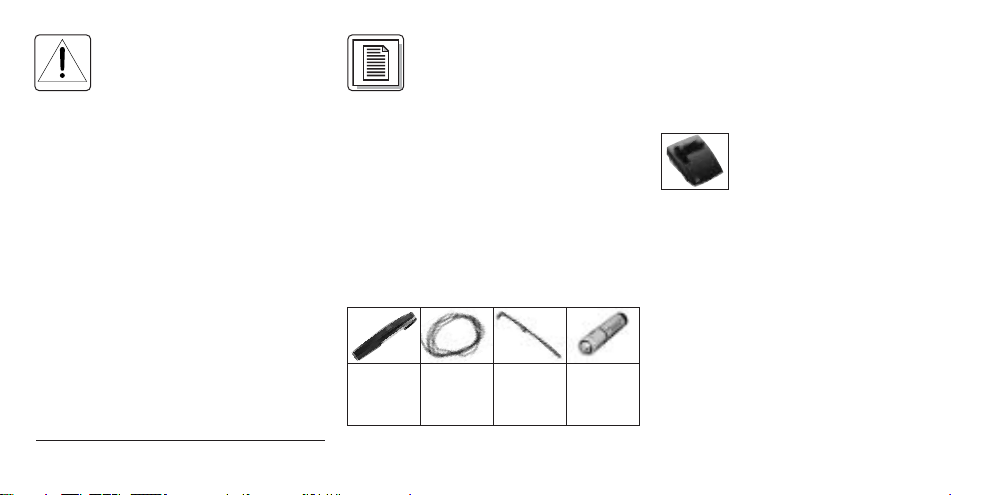
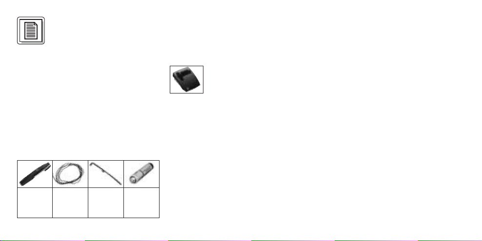
2.2 Lieferumfang
1 Sender
MP 40
micropen
Kontrollieren Sie bitte, ob die Ver-
1 Kordel 1 Ersatz-
clip,
schwarz
1 Batterie
Größe
AAA
packung alle oben angeführten Teile enthält. Falls etwas fehlt, wenden Sie sich
bitte an Ihren AKG-Händler.
2.3 Empfohlenes Zubehör
Ladestation CU 40
2.4 Beschreibung
Der MP 40
Miniatursender mit abnehmbarem
Kondensatormikrofon C 407 mit kugelförmiger Richtcharakteristik. Der Sender
wurde speziell für Sprachübertragung in
Verbindung mit den Empfängern des
Systems WMS 40 von AKG entwickelt.
Der MP 40
fixen, quarzstabilisierten Trägerfrequenz
im UHF-Trägerfrequenzbereich von 710
bis 865 MHz und ist mit einer im
Gehäuse integrierten Dipol-Antenne
ausgestattet.
micropen
micropen
ist ein
arbeitet auf einer
Page 3
In einem Fach am oberen Ende des
Senders ist das Mikrofon untergebracht.
Das Mikrofon ist mit einer Befestigungsklammer ausgestattet und über ein ca.
20 cm langes Kabel mit dem Sender
verbunden. Sie können das Mikrofon
daher vom Sender abnehmen und an
der Kleidung anklemmen.
Der Clip an der Rückseite des Senders
ermöglicht Ihnen, den Sender z.B. an der
Hemdtasche zu fixieren. Die Farbe des
Clips entspricht der Trägerfrequenz des
Senders. Sie können den Clip aber auch
gegen den mitgelieferten schwarzen
Ersatzclip austauschen.
Mittels der mitgelieferten Kordel können
Sie sich den Sender auch umhängen.
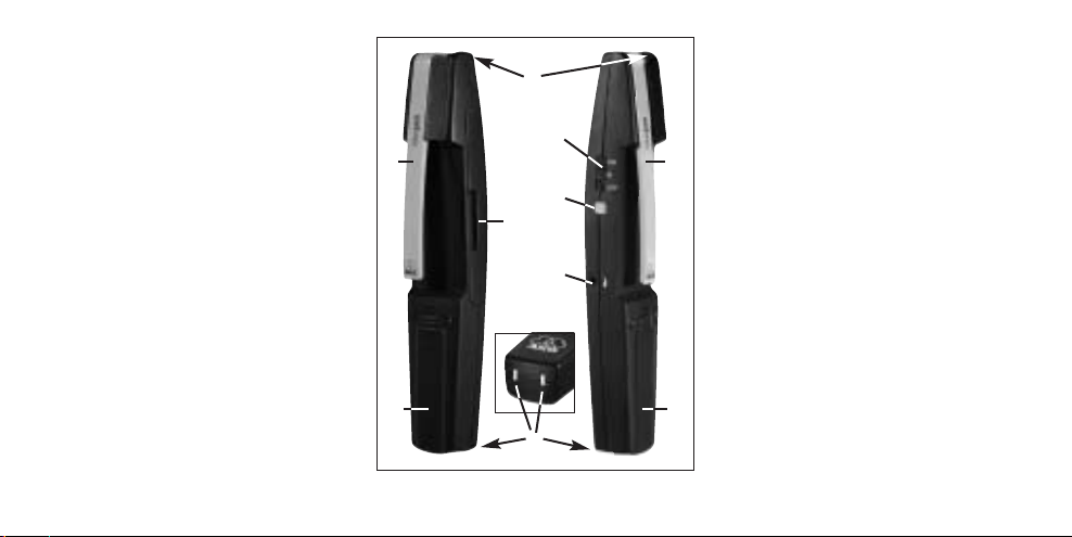
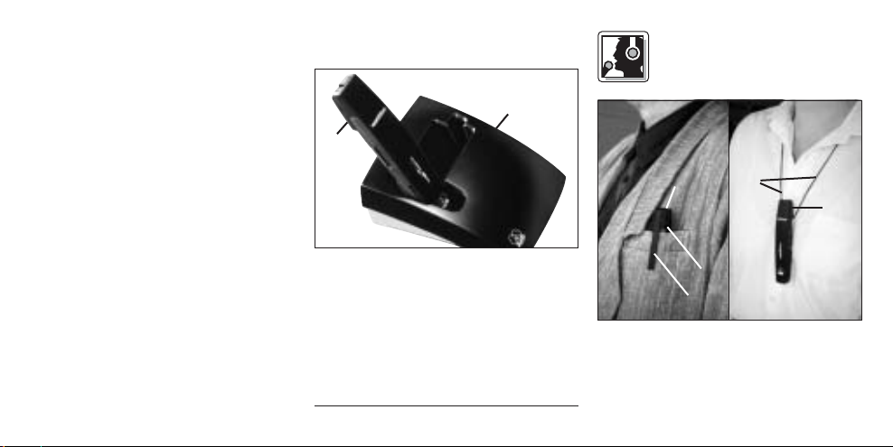
2.5 Bedienelemente (siehe Abb. 1)
1 ON/MUTE/OFF: Dieser Schiebe-
schalter hat drei Stellungen:
ON: Die Spannungsversorgung für
den Sender ist eingeschaltet.
Abb. 1: Bedienelemente MP 40
M: Das vom Mikrofon kommende
Audiosignal ist stummgeschaltet,
Spannungsversorgung und HFTrägerfrequenz bleiben jedoch eingeschaltet. Dadurch wird der
Empfänger trotz abgeschaltetem
Mikrofon nicht durch andere Sender
gestört.
OFF: Die Spannungsversorgung für
den Sender ist ausgeschaltet.
2 Kontroll-LED: Diese LED zeigt den
Ladezustand der Batterie an.
LED leuchtet beim Einschalten kurz
auf und erlischt wieder: Batterie in
Ordnung.
LED leuchtet konstant: Batterie in ca.
60 Minuten erschöpft.
3 Eingangspegelregler: Stellt die
Empfindlichkeit des Audioeingangs
ein.
4 Batteriefach für 1 Stk. 1,5 V-Batterie
Größe AAA (mitgeliefert).
5 Ladekontakte zum Aufladen eines
3
Page 4
Akkus im Batteriefach mit Hilfe der
optionalen Ladestation CU 40.
6 Halteclip zur Befestigung des
Senders in der Hemdtasche oder
Brusttasche eines Sakkos.
Die Farbe des Halteclips zeigt die
Trägerfrequenz des Senders an.
7 Mikrofon
8 Kabelfachdeckel: Im Kabelfach unter
dem Kabelfachdeckel befindet sich
das ca. 20 cm lange Mikrofonkabel.
4
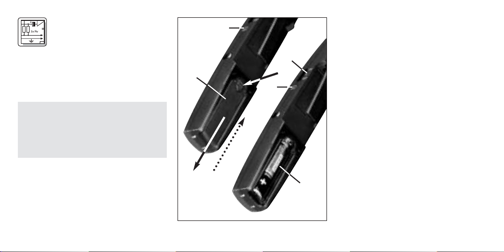
3 Inbetriebnahme
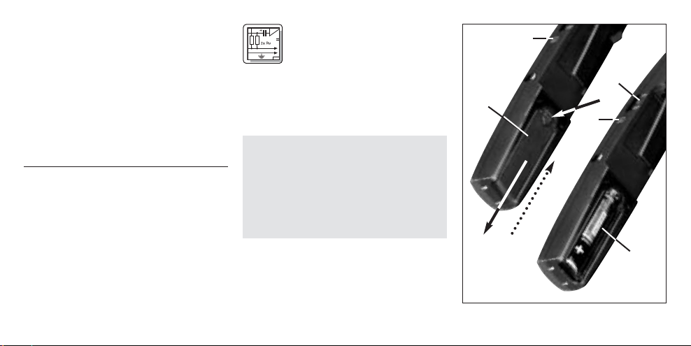
3.1 Batterie einlegen/
austauschen und testen
Siehe Abb. 2:
1. Drücken Sie den Schnapphaken am
Batteriefachdeckel (1) nach unten.
2. Ziehen Sie den Batteriefachdeckel (1)
nach unten vom Sender ab.
Wichtig: Der Schaumstoffpolster an der
Innenseite des Batteriefachdeckels
(1) fixiert die Batterie in ihrer Position.
Entfernen Sie den Schaumstoffpolster nicht, da die Batterie ansonsten nicht richtig im Batteriefach
fixiert ist und Klappergeräusche verursachen kann.
3. Wenn sich eine leere oder defekte
Batterie im Batteriefach befindet,
nehmen Sie diese heraus.
4. Legen Sie die mitgelieferte bzw. neue
Batterie (2) wie in Abb. 2 gezeigt in
das Batteriefach ein.
Abb. 2: Batterie einlegen
Page 5
5. Stellen Sie den ON/MUTE/OFFSchalter (3) auf ON.
Die Kontroll-LED (4)blitzt kurz auf. Wenn
die Batterie in gutem Zustand ist, erlischt
die Kontroll-LED (4)wieder.
Wenn die Kontroll-LED (4)zu leuchten
beginnt, ist die Batterie in ca. 60 Minuten
erschöpft. Tauschen Sie die Batterie
möglichst bald gegen eine frische aus.
Wenn die Kontroll-LED (
blitzt, ist die Batterie erschöpft.
Legen Sie eine neue Batterie ein.
6. Schieben Sie den Batteriefachdeckel (1) gegen die Pfeilrichtung auf
den Sender, bis der Batteriefachdeckel (1) einrastet.
3.2 Betrieb mit Akku (siehe Abb. 3)
Sie können den Sender anstelle einer
normalen Baterie auch mit einem 1,5 VAkku betreiben. Wir empfehlen NiMHAkkus des Typs SANYO HR-4U
4)
nicht auf-
(650 mAh) oder Panasonic Rechargeable
PRO+ (550 mAh).
Abb. 3: Akku aufladen mit optionaler
Ladestation CU 40
Zum Aufladen des Akkus brauchen Sie
nur den Sender (1) wie in Abb. 3 gezeigt
in die optionale Ladestation CU 40 (2) zu
stellen.
Nähere Hinweise dazu finden Sie in der
Bedienungsanleitung der Ladestation
CU 40.
4 Anwendung
4.1 Sender befestigen
(Siehe Abb. 4)
Abb. 4: Sender befestigen
Stecken sie den Sender (1) mit dem
Halteclip (2) nach aussen so in die Hemdtasche oder äussere Brusttasche des
5
Page 6
Sakkos, dass das Mikrofon (3) nach oben
zeigt.
Wenn keine geeignete Tasche zur Verfügung steht, hängen Sie die mitgelieferte
Kordel (4) in den Halteclip (2) ein und legen
Sie die Kordel (4) um den Nacken.
4.2 Pegel einstellen (siehe Abb. 1)
1. Kontrollieren Sie, ob der Empfänger
mit demselben Farbcode gekennzeichnet ist wie der Sender.
2. Drehen Sie den Eingangspregelregler
(3) am Sender mit einem kleinen
Schraubenzieher bis zur Mitte zwischen linkem und rechtem Anschlag
auf.
3. Schalten Sie den Sender ein, indem
Sie den ON/MUTE/OFF-Schalter (1)
auf ON stellen.
4. Schalten Sie den Empfänger und die
Audioanlage ein.
5. Sprechen Sie einige Sätze mit Ihrer
normalen Stimme.
6
6. Sollte Ihre Stimme in den Lautsprechern verzerrt klingen, drehen
Sie den Eingangspegelregler (3) soweit
gegen den Uhrzeigersinn zurück, bis
Sie keine Verzerrung mehr hören.
Sollte Ihre Stimme in den Lautsprechern zu leise klingen, drehen
Sie den Eingangspegelregler (3) im
Uhrzeigersinn auf. Falls die
Lautsprecher infolge akustischer
Rückkopplung zu pfeifen beginnen,
drehen Sie den Eingangspegelregler
(3) sofort wieder zurück, bis das
Pfeifen aufhört.
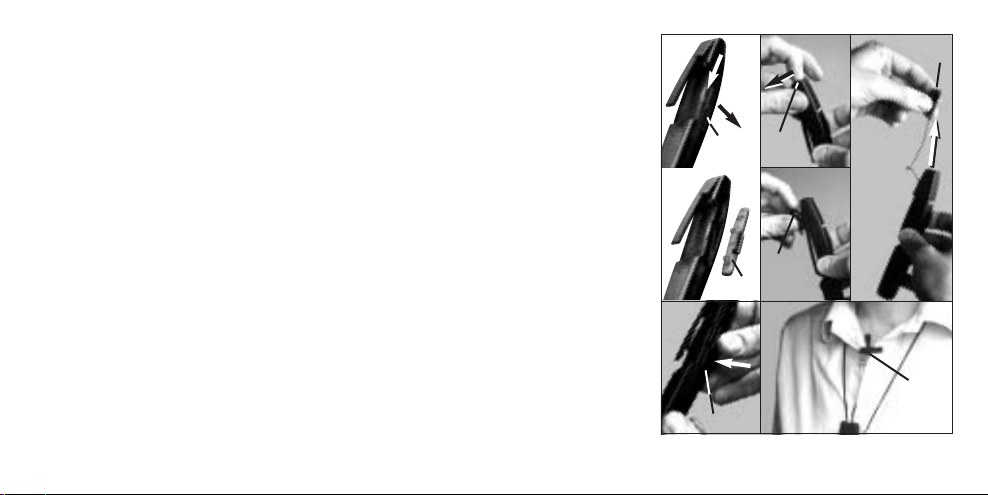
4.3 Mikrofon abnehmen (siehe Abb. 5)
Falls bereits bei geringer Lautstärke
Rückkopplungen auftreten, können Sie
das Mikrofon vom Sender abnehmen
und näher am Mund positionieren. Damit
reduzieren Sie die Gefahr akustischer
Rückkopplungen.
2a.
1. 3.
2b.
4.
Abb. 5: Mikrofon abnehmen
5./6./7.
Page 7
1. Entriegeln und nehmen Sie den
Kabelfachdeckel (1) ab.
2. Setzen Sie den Fingernagel am
Mikrofonkörper an und ziehen Sie
das Mikrofon (3) aus dem Mikrofonfach heraus.
3. Ziehen Sie das Mikrofon (3) vom
Sender weg.
4. Setzen Sie den Kabelfachdeckel (1)
wieder auf das Kabelfach auf und
drücken Sie ihn bis zum Einrasten
hinunter.
5. Stecken Sie den Sender in die Hemdoder äussere Brusttasche oder hängen
Sie ihn mit der Kordel um den Nacken.
6. Klemmen Sie das Mikrofon (3) an der
Knopfleiste oder am Kragen möglichst nahe beim Mund des
Sprechers an.
7. Drehen Sie das Mirofon (3) so, dass
es zum Mund des Sprechers zeigt.
1.
2a. 2b.
3.
4.
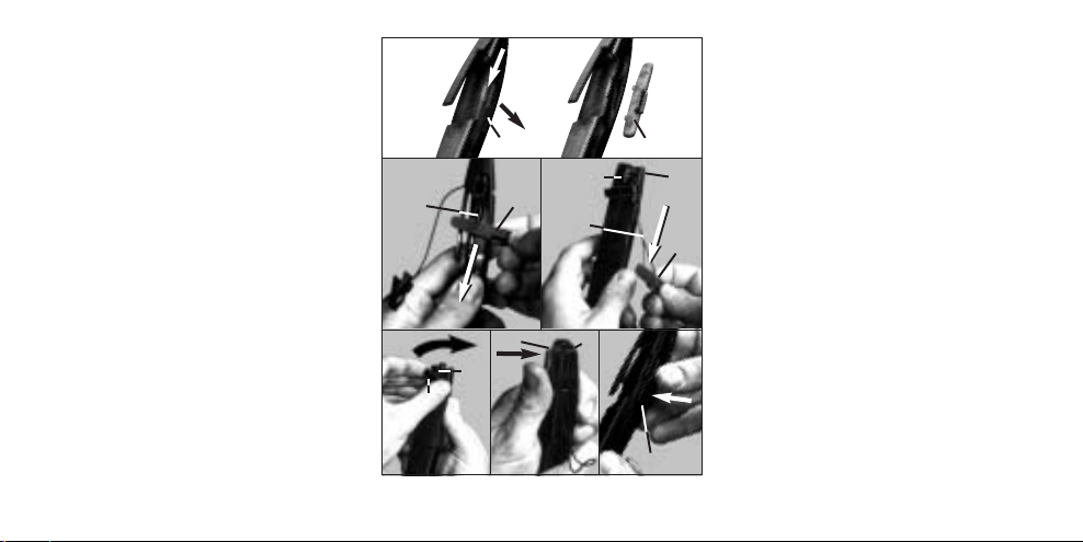
Abb. 6: Mikrofon montieren
4.4 Mikofon am Sender montieren
Siehe Abb. 6:
1. Entriegeln und nehmen Sie den
Kabelfachdeckel (1) ab.
5.
2. Ziehen Sie mit dem Kabelfachdeckel
(1) das Mikrofonkabel (2) soweit nach
unten, bis das Mikrofon (3) auf dem
Mikrofonfach (4) liegt.
3. Drehen Sie die Mikrofonklammer (5)
parallel zum Mikrofon (3).
4. Drücken Sie das Mikrofon (3) in das
Mikrofonfach (4), bis das Mikrofon (3)
einrastet.
5. Verstauen Sie das Mikrofonkabel (2)
im Kabelfach und setzen Sie den
Kabelfachdeckel (1) wieder auf das
Kabelfach auf.
4.5 Sender als Handmikrofon
Sie können den Sender auch, z.B. bei
Interviews, wie ein normales Mikrofon in
der Hand halten.
7
Page 8
Sprechen Sie aus einem Abstand von
ca. 30 cm in das Mikrofon.
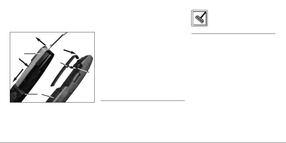
4.6 Halteclip austauschen (Abb. 7)
1.
4.
2.
3.
Abb. 7: Halteclip austauschen
Falls der farbige Halteclip zu auffällig
wirkt, können Sie ihn durch den mitgelieferten schwarzen Halteclip ersetzen:
8
1. Hebeln Sie den Halteclip (1) mit
einem Schraubenzieher vorne vom
Sender (2) ab.
2. Drücken Sie auf den Halteclip (1) und
ziehen Sie den Halteclip (1) nach unten
(Pfeilrichtung) vom Sender (2) ab.
3. Hängen Sie den Haken (3) am
schwarzen Ersatzhalteclip in die Ausnehmung (4) am Sender (2) ein.
4. Drücken Sie das gebogene Ende des
Ersatzhalteclips gegen den Sender
(2), bis der Ersatzhalteclip einrastet.
4.7 Fehlerbehebung
Hinweise zur Fehlerbehebung finden
Sie in der Bedienungsanleitung des
Empfängers.
5 Reinigung
Reinigen Sie das Gehäuse des
Senders mit einem mit Wasser
befeuchteten Tuch.
Page 9
6 Technische Daten
Trägerfrequenz 710 - 865 MHz
Modulation FM
Audioübertragungsbandbreite 40 - 20.000 Hz
Frequenzstabilität (-10°C bis +50°C) ±15 kHz
Nennhub 15 kHz (SP1, SP2: 13,5 kHz)
Klirrfaktor bei 1 kHz typ. 0,8%
Kompander integriert
Signal/Rauschabstand typ. 103 dB(A)
HF-Ausgangsleistung typ. 5 mW
Stromaufnahme typ. 75 mA
Spannungsversorgung 1 x 1,5 V-Batterie Größe AAA
Betriebszeit >10 h (Batterie), >5 h (Akku)
Audio-Eingangspegel für Nennhub 300 mV/1 kHz
Abmessungen (BxTxH) 20 x 25 x 145 mm
Gewicht 36 g
Dieses Produkt entspricht den Normen EN60065:1998, EN301 489-9 v.1.1.1
(09-2000) und EN300 422-2 v.1.1.1(07-2000).
9
Page 10

This equipment has been tested and
FCC Statement
found to comply with the limits for a Class
B digital device, pursuant to Parts 74, 15,
and 90 of the FCC Rules. These limits are
designed to provide reasonable protection against harmful interference in a residential installation. This equipment generates, uses, and can radiate radio frequency energy and, if not installed and
used in accordance with the instructions,
may cause harmful interference to radio
communications. However, there is no
guarantee that interference will not occur
in a particular installation. If this equipment does cause harmful interference to
radio or television reception, which can
be determined by turning the equipment
off and on, the user is encouraged to try
to correct the interference by one or more
of the following measures:
• Reorient or relocate the receiving
antenna.
10
• Increase the separation between the
equipment and the receiver.
• Connect the equipment into an outlet
on a circuit different from that to
which the receiver is connected.
• Consult the dealer or an experienced
radio/TV technician for help.
Shielded cables and I/O cords must be
used for this equipment to comply with
the relevant FCC regulations.
Changes or modifications not expressly
approved in writing by AKG Acoustics
may void the user’s authority to operate
this equipment.
This device complies with Part 15 of the
FCC Rules. Operation is subject to the
following two conditions: (1) this device
may not cause harmful interference, and
(2) this device must accept any interference received, including interference
that may cause undesired operation.
1 Safety and
Environment
1.1 Safety
1. Do not expose the equipment to
direct sunlight, excessive dust, moisture, rain, mechanical vibrations, or
shock.
1.2 Environment
1. Be sure to dispose of used batteries
as required by local waste disposal
rules. Never throw batteries into a fire
(risk of explosion) or garbage bin.
2. When scrapping the equipment,
remove the batteries, separate the
case, circuit boards, and cables, and
dispose of all components in accordance with local waste disposal rules.
Page 11
2 Description
2.1 Introduction
Dear Customer:
Thank you for purchasing an AKG
product. This Manual contains important
instructions for setting up and operating
your equipment. Please take a few
minutes to read the instructions below
carefully before operating the equip-
ment. Please keep the Manual for future
reference. Have fun and impress your
audience!
2.2 Unpacking
1 MP 40
micropen
1 necklace cord
1 replacement clip
(black)
1 AAA
size
bat
tery
Check that the package contains all the
parts listed above. If anything is missing,
please contact your AKG dealer.
2.3 Optional Accessories
CU 40 charger
2.4 Description
The MP 40
transmitter with a detachable C 407
omnidirectional condenser microphone.
The transmitter has been specifically
designed for speech reinforcement use
in conjunction with WMS 40 Series
receivers from AKG.
The MP 40
single fixed, quartz stabilized carrier frequency in the 710 MHz to 865 MHz UHF
band and uses a dipole antenna
integrated in the transmitter body.
micropen
micropen
is a miniature
operates on a
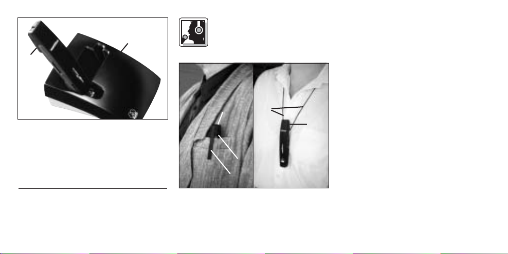
The microphone is nested in a compartment at the upper end of the transmitter.
The microphone is fitted with a fixing
clamp and connected to the transmitter
by a cable approx. 8 inches (20 cm) long.
You can detach the microphone from the
transmitter and clamp the microphone to
the talker's clothes.
The pen-style clip on the rear of the
transmitter allows you to secure the
transmitter, e.g., in a shirt pocket. The
color of the clip indicates the carrier frequency of your transmitter. You can
replace the color code clip with the supplied black replacement clip.
The supplied necklace cord allows you
to wear the transmitter around your
neck.
2.5 Controls (Refer to fig. 1)
1 ON/MUTE/OFF: This slide switch
provides three positions:
ON: Power to the transmitter is on.
11
Page 12
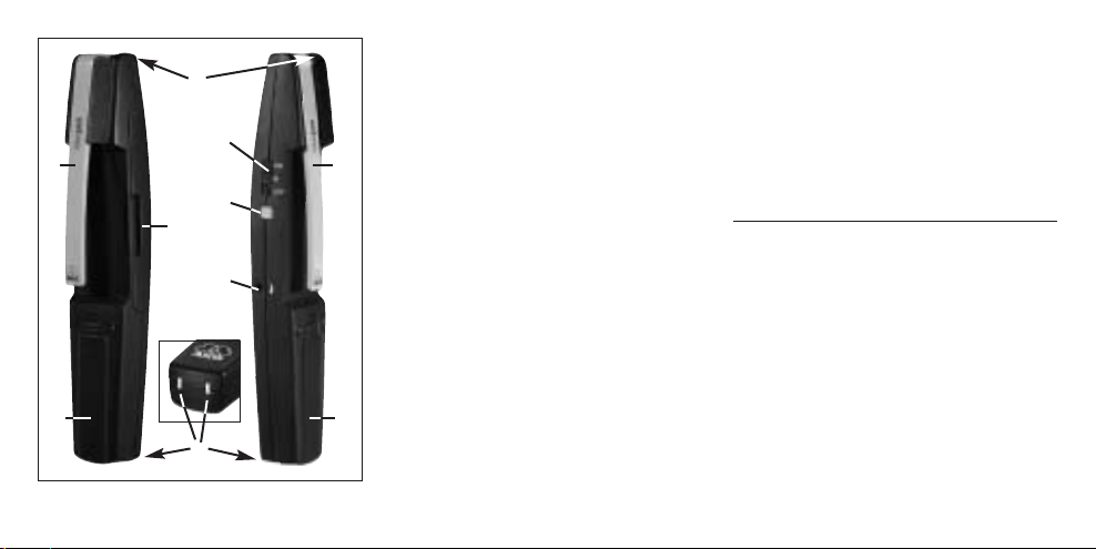
Fig. 1: MP 40 controls.
12
M: The signal delivered by the microphone is muted while power and the
RF carrier frequency remain on. This
prevents the receiver from responding to interference from other transmitters.
OFF: Power to the transmitter is off.
2Status LED: Indicates battery status.
LED flashes momentarily upon switching ON and extinguishes: battery is
OK.
LED lights constantly: battery will be
dead in about 60 minutes.
3 Input Gain: This rotary pot sets the
sensitivity of the transmitter’s audio
section.
4 Battery compartment for one 1.5-V
AAA size battery (supplied).
5 Charging contacts for charging a
rechargeable battery inside the battery compartment using the optional
CU 40 charger.
6Clip for securing the transmitter
inside a shirt pocket or in an outside
breast pocket of a jacket.
The color of the clip indicates the carrier frequency of your transmitter.
7 Microphone
8 Cable compartment lid: The cable
compartment beneath the lid holds
the microphone cable (approx.
8 inches/20 cm long).
Page 13
3 Setting Up
3.1 Inserting/Replacing and
Testing the Battery
Refer to fig. 2:
1. Depress the snap hook on the battery
compartment lid (1).
2. Pull the battery compartment lid (1)
down to remove it from the transmitter.
Important: The foam pad on the inside
of the battery compartment lid (1)
holds the battery in place. Do not
remove the foam pad. If you do, the
battery will not be held in place properly and may cause a rattling noise.
3. If there is a dead or defective battery
inside the battery compartment,
remove the battery.
4. Insert the supplied or new battery (2)
into the battery compartment as
shown in fig. 2.
5. Set the ON/MUTE/OFF switch (3) to ON.
Fig. 2: Inserting the battery.
The status LED (4) will flash momentarily. If the battery is in good condition,
the status LED (4) will extinguish.
If the status LED (4) lights constantly
the battery will be dead within about
60 minutes. Replace the battery with
a new one as soon as possible.
If the status LED (4) fails to flash
momentarily the battery is dead.
Insert a new battery.
6. Slide the battery compartment lid (1)
onto the transmitter against the
direction of the arrow to the point that
the lid (1) will click shut.
3.2 Using Rechargeable Batteries
Refer to fig. 3:
Instead of dry batteries, you can also
use a 1.5-V rechargeable battery to
power the transmitter. We recommend
SANYO HR-4U (650 mAh) or Panasonic
Rechargeable PRO+ (550 mAh) NiMH
rechargeable batteries.
13
Page 14
4 Operating Notes
Refer to fig. 4:
4.1 Attaching the
Transmitter
the talker's jacket, making sure the clip
(2) will be on the outside of the pocket
and the microphone (3) will point
upward.
If no suitable pocket is available, slip the
supplied necklace cord (4) under the clip
(2) and place the necklace cord (4)
around the talker's neck.
Fig. 3: Using the CU 40 optional charger.
To charge the battery, insert the transmitter (1) into the optional CU 40 charger
(2) as shown in fig. 3.
For details, refer to the CU 40 charger
manual.
14
Fig. 4: Attaching the transmitter.
Slide the transmitter (1) into a shirt
pocket or an outside breast pocket of
4.2 Setting Levels (Refer to fig. 1)
1. Check that the receiver is marked
with the same color code as the
transmitter.
2. Use a small screwdriver to turn the
input gain control (3) on the transmitter to a position halfway between
the left and right stops.
3. Set the ON/MUTE/OFF switch (1) to ON
to switch power to the transmitter on.
4. Switch power to your sound system
or amplifier on.
5. Speak a few sentences in your
normal voice.
Page 15
6. If your voice sounds distorted on the
loudspeakers turn the input gain control (3) down CCW to the point that
you will hear no more distortion.
If your voice sounds too quiet on the
loudspeakers, turn the input gain
control (3) up CW. If the loudspeakers
start howling due to acoustic feedback, immediately turn the input gain
control (3) back down to the point
that the howling will stop.
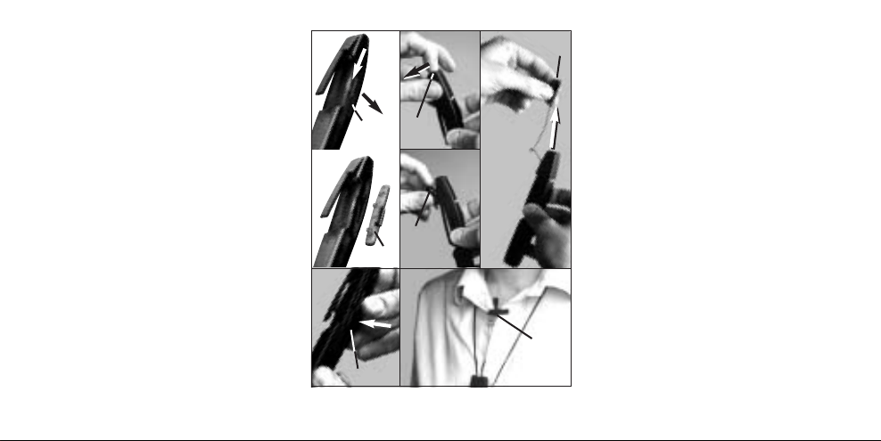
4.3 Detaching the Microphone
Refer to fig. 5):
If feedback occurs even at low volume
levels, you can detach the microphone
from the transmitter and position it
closer to the talker's mouth to reduce
the risk of acoustic feedback.
1. Unlock and remove the cable compartment lid (1).
2. Place your fingernail against the
2a.
1. 3.
2b.
4.
Fig. 5: Detaching the microphone.
5./6./7.
microphone body and pull the microphone (3) out of the microphone
compartment.
3. Pull the microphone (3) away from
the transmitter.
4. Replace the cable compartment lid (1)
on the cable compartment and press
the lid (1) down to make it snap shut.
5. Put the transmitter in the shirt pocket
or outside breast pocket or hang it
around the talker's neck with the
necklace cord.
6. Clamp the microphone (3) on the selvage or the collar as close as
possible to the talker's mouth.
7. Turn the microphone (3) to aim it at
the talker's mouth.
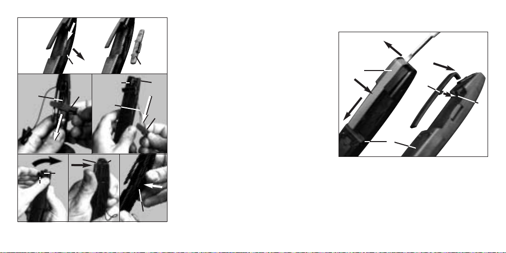
4.4 Mounting the Microphone on
the Transmitter
Refer to fig. 6:
1. Unlock and remove the cable compartment lid (1).
15
Page 16
1.
2a. 2b.
3.
5.
4.
Fig. 6: Mounting the microphone.
16
2. Use the cable compartment lid (1) to
pull the microphone cable (2) down to
the point that the microphone (3) will
rest against the microphone com-
partment (4).
3. Set the microphone clamp (5) parallel
to the microphone (3).
4. Press the microphone (3) into the
microphone compartment (4) to the
point that the microphone (3) snaps
into place.
5. Stow the microphone cable (2) in the
cable compartment and replace the
cable compartment lid (1) on the
cable compartment.
4.5 Handheld Use
For interviews and similar applications,
you can hold the transmitter in your
hand like a normal microphone.
Talk into the microphone from approx.
1 foot (30 cm) away.
4.6 Replacing the Clip (Fig. 7)
1.
4.
2.
3.
Fig. 7: Replacing the Clip
If the color code clip looks too garish
you can replace it with the supplied
black clip.
1. Use a screwdriver to lever the clip (1)
away from the front end of the transmitter (2).
Page 17

2. Press down on the clip (1) and pull
the clip (1) away from the transmitter
(2) in the direction of the arrow.
3. Nest the hook (3) on the black
replacement clip into the matching
opening (4) in the transmitter (2).
4. Press the bent end of the replacement clip against the transmitter (2)
to make it snap into place.
4.7 Troubleshooting
For troubleshooting hints, refer to your
receiver manual.
5 Cleaning
To clean the transmitter case,
use a soft cloth moistened with
water.
6 Specifications
Carrier frequency range 710 to 865 MHz
Modulation FM
Audio bandwidth 40 to 20,000 Hz
Frequency stability (-10°C to +50°C) ±15 kHz
Rated deviation 15 kHz (SP1, SP2: 13.5 kHz)
T.H.D. at 1 kHz typ. 0.8%
Compander integrated
Signal/noise ratio typ. 103 dB(A)
RF output typ. 5 mW
Current consumption typ. 75 mA
Power requirement single 1.5-V AAA size battery
Battery life >10 hours (dry battery)
>5 hours (rechargeable battery)
Audio input level for rated deviation 300 mV/1 kHz
Size (WxDxH) 20 x 25 x 145 mm (0.8 x 1 x 5.7 in.)
Net weight 36 g (1.3 oz.)
This product complies with the following standards: EN60065:1998, EN301 489-9
v.1.1.1(09-2000), and EN300 422-2 v.1.1.1(07-2000).
17
Page 18

1 Sécurité et
écologie
1.1. Sécurité
1. Ne placez jamais l’appareil à un
endroit où il risque d’être exposé
directement au soleil, à une atmosphère poussiéreuse, à l’humidité, à la
pluie, aux vibrations ou aux secousses.
1.2. Ecologie
1. Conformez-vous aux règlements en
vigueur pour la mise au rebut des
piles usées. Ne mettez jamais des
piles ni au feu (risque d’explosion) ni
aux ordures ménagères.
2. Si vous mettez l'appareil à la ferraille,
enlevez les piles ou les accus, séparez le boîtier, l'électronique et les
câbles et éliminez les différents éléments conformément aux règlements
en vigueur.
18
2 Description
2.1 Introduction
choisi un produit AKG.
Pour profiter au maximum des avantages que vous offre le WMS 40, lisez très
attentivement ce mode d’emploi avant
la mise en service de l’appareil.
Conservez soigneusement le mode
d’emploi pour pouvoir le consulter lorsque vous vous posez des questions.
Nous vous souhaitons beaucoup de
succès.
2.2. Equipement fourni
1
MP 40
micropen
Contrôlez si le carton contient bien tous
Nous vous remercions d’avoir
émetteur
1 cordelière
1
clip de
rechange,
noir
1 pile
dimension
AAA
les éléments énumérés ci-dessus. Si ce
n’est pas le cas, veuillez contacter votre
distributeur AKG.
2.3 Accessoires optionnels
Chargeur CU 40
2.4 Description
Le MP 40
miniature équipé du microphone électrostatique C 407 omnidirectif. Cet
émetteur a été conçu spécialement pour
la transmission de la parole en liaison
avec les récepteurs AKG de la gamme
WMS 40.
Le MP 40
une porteuse fixe, stabilisée par quartz,
dans la gamme de fréquences UHF de
710 à 865 MHz, possède une antenne
dipôle intégrée dans le boîtier.
micropen
micropen
est un émetteur
qui fonctionne sur
Page 19

Le micro est encastré dans un logement
sur le haut de l’émetteur. Il est doté
d’une agrafe et est relié à l’émetteur par
un câble de 20 cm environ. On peut
donc sortir le micro de l’émetteur et le
fixer aux vêtements.
Le clip au dos de l’émetteur permet de
fixer celui-ci p.ex. à la poche de chemise. La couleur du clip indique la fréquence porteuse. Vous pouvez, si vous le
souhaitez, remplacer le clip de couleur
par le clip noir fourni.
Vous pouvez aussi utiliser la cordelière
qui permet de porter l’émetteur autour
du cou.
2.5 Eléments de commande
1 ON/MUTE/OFF: Ce curseur peut
occuper trois positions :
ON : L’émetteur est sous tension.
M : Le signal audio venant du micro
est sur muet mais l’émetteur reste
sous tension et sur la porteuse HF.
(Cf. Fig. 1)
Fig. 1 : Eléments de commande du MP 40
Ceci permet de couper le micro sans
que le récepteur ne soit perturbé par
d’autres émetteurs.
OFF : L’émetteur n’est pas sous tension.
2 LED témoin : Cette LED indique l’u-
sure de la pile.
La LED lance un éclair quand on met
l’émetteur sous tension puis s’éteint
aussitôt : la pile est en bon état.
La LED reste allumée : la pile n’assure plus que 60 minutes d’autonomie.
3 Potentiomètre d’entrée : règle la
sensibilité de l’entrée audio.
4Compartiment de la pile pour une
pile de 1,5 V, dimension AAA
(fournie).
5 Contacts pour charger un accu
dans le compartiment de la pile à l’aide du chargeur optionnel CU 40.
6 Clip : permettant de fixer l’émetteur à
la poche de chemise ou à la poche
de poitrine d’un veston.
19
Page 20

La couleur du clip correspond à la
porteuse de l’émetteur.
7 Microphone
8Couvercle du logement du câble :
le câble du micro de 20 cm environ
est logé sous le couvercle.
20
3 Mise en service
3.1 Mise en place/remplacement et essai de la pile
Voir Fig. 2 :
1. Poussez le fermoir du couvercle du
compartiment de la pile (1) vers le
bas.
2. Enlevez le couvercle du compartiment de la pile (1) en le faisant glisser
vers le bas.
Important : La plaque de mousse à
l’intérieur du couvercle du compartiment de la pile (1) maintient la pile en
position. N’enlevez pas cette plaque,
sinon la pile ne serait pas maintenue
correctement et risquerait de provoquer des bruits importuns.
3. Enlevez, le cas échéant, la pile
épuisée ou défectueuse se trouvant
dans le compartiment.
4. Mettez la pile fournie ou la nouvelle
Fig. 2 : Mise en place de la pile
Page 21

pile (2) dans le compartiment comme
indiqué à la Fig. 2.
5. Faites occuper au curseur
ON/MUTE/OFF (3) la position ON.
La LED témoin (4) lance un éclair. Si
la pile est en bon état, la LED (4) s’éteint aussitôt.
Si la LED (4) reste allumée, la pile
n’assure plus que 60 minutes d’autonomie. Remplacez-la dès que possible par une pile fraîche.
Si la LED (4) ne s’allume pas, la pile
est épuisée et doit être changée.
6. Remettez le couvercle du compartiment de la pile (1) sur l’émetteur en le
faisant glisser dans le sens inverse de
la flèche jusqu’à enclenchement.
3.2 Fonctionnement sur accu
Voir Fig. 3:
Au lieu d’une pile normale, vous pouvez
également utiliser un accu de 1,5 V.
Nous recommandons les accus NiMH,
type SANYO HR-4U (650 mAh) ou
Panasonic Rechargeable PRO+
(550 mAh).
Fig. 3 : Recharge de l’accu à l’aide du
chargeur optionnel CU 40
Pour recharger l’accu il suffit d’introduire
l’émetteur (1) dans le chargeur optionnel
CU 40 (2) comme indiqué à la Fig. 3.
Pour plus de détails, veuillez consulter le
mode d’emploi du chargeur CU 40.
4 Mode opératoire
4.1 Fixation de l’émetteur
poche de chemise ou dans la poche de
poitrine extérieure du veston de sorte
que le clip (2) se trouve à l’extérieur et
que le micro (3) soit tourné vers le haut.
Fig. 4 : Fixation de l’émetteur
Fixez l’émetteur (1) dans la
21
Page 22

En l’absence de poche appropriée,
accrochez la cordelière (4) au clip (2) et
passez-la autour du cou (Fig. 4).
4.2 Réglage de niveau (Cf. Fig. 1)
1. Contrôlez si le récepteur a bien le
même code couleur que l’émetteur.
2. A l’aide d’un petit tournevis, réglez le
potentiomètre d’entrée (3) de l’émetteur sur la position médiane, à égale
distance des butées droite et gauche.
3. Mettez l’émetteur sous tension en
amenant le curseur ON/MUTE/OFF
(1) sur ON.
4. Mettez le récepteur et l’équipement
audio sous tension.
5. Prononcez quelques phrase sur un
ton normal.
6. Si votre voix arrive déformée aux
haut-parleurs, faites tourner le potentiomètre d’entrée (3) dans le sens
inverse des aiguilles de la montre jusqu’à disparition des distorsions.
22
Si votre voix arrive sous un niveau
trop faible aux haut-parleurs, faites
tourner le potentiomètre d’entrée (3)
dans le sens des aiguilles de la montre. Si les haut-parleurs se mettent à
siffler parce qu’il y a du larsen tournez aussitôt le réglage (3) dans le
sens inverse jusqu’à ce que les sifflements s’arrêtent.
4.3 Détacher le micro de
l’émetteur (voir Fig. 5)
Si le larsen se produit dès un faible volume, vous pouvez détacher le micro de
l’émetteur et le positionner plus près des
lèvres. Vous réduisez ainsi le risque
d’accrochage.
1. Déverrouillez le couvercle du logement du câble (1) et enlevez-le.
2. Glissez l’ongle sous le boîtier du
micro (3) et extrayez-le de son logement.
2a.
1. 3.
2b.
4.
Fig. 5 : Détacher le micro de l’émetteur
5./6./7.
Page 23

3. Eloignez le micro (3) de l’émetteur.
4. Remettez le couvercle du logement
du câble (1) en place en le faisant
glisser jusqu’à enclenchement.
5. Mettez l’émetteur dans la poche de
chemise ou dans la poche extérieure
du veston ou accrochez-le à la cordelière pour le mettre autour du cou.
6. Fixez le micro (3) à la boutonnière ou
au col, aussi près que possible des
lèvres du locuteur.
7. Orientez le micro (3) vers les lèvres du
locuteur.
4.4 Montage du micro sur l’émetteur
Voir Fig. 6 :
1. Déverrouillez le couvercle du logement du câble (1) et enlevez-le.
2. A l’aide du couvercle du logement du
câble (1), tirez le câble du micro (2)
vers le bas jusqu’à ce que le micro (3)
repose sur le moulage (4).
3. Orientez l’attache du micro (5) par-
1.
2a. 2b.
3.
4.
Fig. 6 : Montage du micro
allèlement au micro (3).
4. Enfoncez le micro (3) dans le moulage (4) jusqu’à ce qu’il s’enclenche.
5. Rangez le câble du micro (2) dans
5.
son compartiment et remettez le couvercle (8) sur le compartiment du
câble.
4.5 Utilisation de l’émetteur en
tant que micro à main
Vous pouvez aussi, par exemple pour les
interviews, tenir l’émetteur à la main,
comme un micro normal.
Le micro doit se trouver à environ 30 cm
des lèvres du locuteur.
4.6 Remplacement du clip (Fig. 7)
Si le clip de couleur se voit trop vous
pouvez le remplacer par le clip noir
fourni :
23
Page 24

1.
4.
2.
3.
Fig. 7 : Remplacement du clip
1. A l’aide d’un tournevis, soulevez le
clip (1) sur l’avant pour le détacher de
l’émetteur (2).
2. Exercez une pression sur le clip (1) et
tirez-le vers le bas (dans le sens de la
flèche).
3. Introduisez le crochet (3) du clip noir
24
dans l’encoche (4) de l’émetteur (2).
4. Appuyez sur l’extrémité recourbée du
clip jusqu’à ce que celui-ci s’enclenche dans l’émetteur (2).
4.7 Dépannage
Vous trouverez les instructions relatives
au dépannage dans le mode d’emploi de
votre récepteur.
5 Nettoyage
Le boîtier de l’émetteur se nettoie avec un chiffon humecté
d’eau.
Page 25

6 Caractéristiques techniques
Fréquence porteuse 710 - 865 MHz
Modulation FM
Bande passante audio 40 - 20.000 Hz
Stabilité de fréquence (entre -10°C et +50°C) ±15 kHz
Excursion nominale 15 kHz (SP1, SP2 : 13,5 kHz)
Distorsion typ. (par harmonique) pour 1 kHz 0,8 %
Compresseur-expanseur intégré
Rapport signal sur bruit typ. 103 dB (A)
Puissance sortie HF typ. 5 mW
Consommation typ. 75 mA
Alimentation 1 pile de 1,5 V, dimension AAA
Autonomie > 10 h (pile), > 5 h (accu)
Niveau d’entrée audio pour l’excursion nominale 300 mV/1kHz
Dimensions (l x p x h) 20 x 25 x 145 mm
Poids net 36 g
Ce produit est conforme aux normes EN60065:1998, EN301 489-9 v.1.1.1(09-2000) et
EN300 422-2 v.1.1.1(07-2000).
25
Page 26

1 Sicurezza ed
ambiente
1.1 Sicurezza
1. Non esponete l’apparecchio diretta-
mente al sole, alla polvere e all'umidità,
alla pioggia, a vibrazioni o a colpi.
1.2 Ambiente
1. Smaltite le batterie usate e gli accu-
mulatori usati sempre conformemente alle norme di smaltimento rispettivamente vigenti. Non gettate le batterie o gli accumulatori nel fuoco
(pericolo di esplosione) o nei rifiuti
residui.
2. Se rottamate l’apparecchio, togliete
le batterie risp. gli accumulatori,
separate scatola, elettronica e cavi e
smaltite tutti i componenti conformemente alle norme di smaltimento
vigenti per essi.
26
2 Descrizione
2.1 Introduzione
prodotto dell‘AKG. Leggete per favore
attentamente le istruzioni per l’uso
prima di usare l’apparecchio e conservate le istruzioni per l’uso per poterle
consultare in caso di necessità. Vi auguriamo buon divertimento e molto successo!
2.2. In dotazione
Controllate per favore se la confezione
contiene tutti i componenti di cui sopra.
Vi ringraziamo di aver scelto un
1 MP 40
micropen
1
cordon-
cino
1 clip di
riserva,
nero
1 batteria
dimensione
AAA
Se manca qualcosa rivolgetevi al vostro
rivenditore AKG.
2.3 Accessori raccomandati
Stazione di carica CU 40
2.4 Descrizione
L’MP 40
miniatura con un microfono staccabile a
condensatore C 407, dalla direttività
omnidirezionale. Il trasmettitore è stato
sviluppato appositamente per la trasmissione della lingua parlata, da realizzarsi insieme ai ricevitori del sistema
WMS 40 della AKG.
L’MP 40
quenza portante fissa, stabilizzata a
quarzo, nella gamma delle frequenze
UHF da 710 a 865 MHz ed è dotato di
un’antenna a dipolo integrata nella scatola del trasmettitore.
micropen
micropen
è un trasmettitore in
lavora su una fre-
Page 27

Il microfono si trova in uno scomparto
disposto all’estremità superiore del trasmettitore. Il microfono è dotato di un clip
di fissaggio ed è collegato al trasmettitore attraverso un cavo lungo 20 cm circa.
Potete anche staccare il microfono dal
trasmettitore e fissarlo sull’abbigliamento.
Il clip sul retro del trasmettitore vi permette di fissare il trasmettitore p.e. nella tasca
della camicia. Il colore del clip corrisponde alla frequenza portante del trasmettitore. Potete anche sostituire il clip con il
clip di riserva nero in dotazione.
Il cordoncino in dotazione serve per
portare il trasmettitore a tracolla.
2.5 Elementi di comando (vedi fig. 1)
1 ON/MUTE/OFF: Questo interruttore
a scorrimento ha tre posizioni:
ON: L’alimentazione del trasmettitore
è inserita.
M: Il segnale audio proveniente dal
microfono è silenziato, la tensione
Fig. 1: Elementi di comando dell’MP 40
d’alimentazione e la frequenza portante RF rimangono inseriti. In questo
modo il trasmettitore non viene
disturbato da altri trasmettitori anche
quando il microfono non è acceso.
OFF: L’alimentazione del trasmettitore è spenta.
2 LED di controllo: Questo LED indica
lo stato di carica della batteria.
Il LED si accende brevemente al
momento dell’accensione e si spegne subito dopo: la batteria è o.k.
Il LED rimane acceso permanentemente: la batteria si esaurirà nei prossimi 60 minuti circa.
3 Regolatore del livello d’ingresso:
regola la sensibilità dell’ingresso audio.
4 Scomparto batteria per 1 batteria da
1,5 V dimensione AAA (in dotazione).
5 Contatti di carica per caricare un
accumulatore nello scomparto batteria con l’aiuto dell’opzionale stazione
di carica CU 40.
27
Page 28

6 Clip di fissaggio: Per fissare il tras-
mettitore nella tasca della camicia o
della giacca.
Il colore del clip indica la frequenza
portante del trasmettitore:
7 Microfono
8 Coperchio scomparto cavo: Nello
scomparto del cavo, sotto il
coperchio, si trova il cavo microfonico lungo 20 cm circa.
28
3 Messa in funzione
3.1 Inserire/sostituire e
testare la batteria
Vedi fig. 2:
1. Premete verso il basso il gancio ad
innesto disposto sul coperchio dello
scomparto batteria (1).
2. Sfilate il coperchio dello scomparto
batteria (1) dal trasmettitore tirando il
coperchio verso il basso.
Importante: Il cuscinetto in espanso fis-
sato sul lato interno del coperchio
dello scomparto batteria (1) fissa la
batteria nella sua posizione. Non
togliete il cuscinetto perché altrimenti la batteria non è fissata bene nello
scomparto e può causare rumori.
3. Se c’è una batteria esausta o difettosa nello scomparto batteria, toglietela.
4. Inserite la batteria in dotazione o una
Fig. 2: Come inserire la batteria
Page 29

nuova (2) nello scomparto batteria
come indicato nella fig. 2.
5. Portate l’interruttore ON/MUTE/OFF
(3) in posizione ON.
Il LED di controllo (4) si accende brevemente. Se la batteria è in buono
stato, il LED di controllo (4) si spegne
subito.
Se il LED di controllo (4) si accende
rimanendo acceso, la batteria si
esaurirà nei prossimi 60 minuti circa.
Sostituitela al più presto con una
nuova.
Se il LED di controllo (4) non si
accende nemmeno brevemente, la
batteria è esausta. Inserite una batteria nuova.
6. Mettete il coperchio dello scomparto
batteria (1) sul trasmettitore, facendolo scorrere contro la direzione della
freccia fin quando il coperchio (1)
scatta.
3.2 Esercizio con accumulatori
Vedi fig. 3:
Fig. 3: Come caricare l’accumulatore
con l’opzionale stazione di carica CU 40
Potete far funzionare il trasmettitore
anche con un accumulatore da 1,5 V al
posto di una batteria. Vi raccomandiamo
di usare accumulatori NiMH del tipo
SANYO HR-4U (650 mAh) oppure del
tipo Panasonic Rechargeable PRO+
(550 mAh).
Per caricare l’accumulatore, basta piazzare il trasmettitore (1) nell’opzionale
stazione di carica CU 40 (2) come indicato nella fig. 3.
Per indicazioni più dettagliate consultate
le istruzioni per l’uso della stazione di
carica CU 40.
29
Page 30

4 Impiego
4.1 Come fissare il
trasmettitore
Vedi fig. 4:
Fig. 4: Come fissare il trasmettitore
Inserite il trasmettitore (1) con il clip di
fissaggio (2) rivolto verso l’esterno nella
30
tasca della camicia o nella tasca esterna
della giacca in modo che il microfono (3)
punti verso l’alto.
Se non c’è una tasca dove piazzare il
trasmettitore, inserite il cordoncino in
dotazione (4) nel clip di fissaggio (2) e
appendete il trasmettitore intorno al
collo.
4.2 Come regolare il livello
1. Controllate se il ricevitore ha lo stesso codice di colore del trasmettitore.
2. Aprite il regolatore del livello d’ingresso (3) disposto sul trasmettitore
girandolo con un piccolo cacciavite
fin quando si trova al centro tra arresto sinistro e quello destro.
3. Inserite il trasmettitore portando l’interruttore ON/MUTE/OFF (1) in posizione ON.
4. Inserite il ricevitore e l’impianto
audio.
5. Dite alcune frasi con la vostra voce
(vedi fig. 1)
abituale.
6. Se la vostra voce viene riprodotta
distorta dagli altoparlanti, portate
indietro il regolatore del livello d’ingresso (3) in senso antiorario fin
quando non sentite più distorsioni.
Se la vostra voce viene riprodotta
troppo bassa dagli altoparlanti, portate avanti il regolatore del livello d’ingresso (3) girandolo in senso orario.
Se gli altparlanti cominciano a fischiare a causa del feedback acustico,
riportate subito indietro il regolatore
del livello d’ingresso (3) fin quando il
fischio cessa.
4.3 Come staccare il microfono
Vedi fig. 5:
Se si verificano dei feedback già a volumi bassi, potete staccare il microfono
dal trasmettitore e posizionarlo più vicino alla bocca. In questo modo riducete il
pericolo di feedback acustici.
Page 31

2a.
1. 3.
2b.
4.
Fig. 5: Come staccare il microfono
5./6./7.
1. Sbloccate il coperchio dello scom-
parto del cavo (1) e sfilatelo.
2. Estraete il microfono (3) dallo scomparto microfonico mettendo l’unghia
di un dito nell’apposita sede sul
corpo microfonico.
3. Sfilate il microfono (3) dal trasmettitore.
4. Rimontate il coperchio dello scomparto del cavo (1) sullo scomparto del
cavo e premetelo verso il basso fin
quando scatta.
5. Mettete il trasmettitore nella tasca
della camicia o nella tasca esterna
della giacca o appendetelo sul collo
servendovi del cordoncino in dotazione.
6. Fissate il microfono (3) sull’orlo dei
bottoni o sul bavero, il più vicino possibile alla bocca dell’oratore.
7. Girate il microfono (3) in modo che
punti verso la bocca dell’oratore.
4.4 Come montare il microfono sul
trasmettitore
Vedi fig. 6:
1. Sbloccate il coperchio dello scomparto del cavo (1) e sfilatelo.
2. Tirate il cavo microfonico (2) verso il
basso tramite il coperchio dello
scomparto del cavo (1), fin quando il
microfono (3) viene a trovarsi sullo
scomparto microfonico (4).
3. Girate il clip microfonico (5) in modo
che sia parallelo al microfono (3).
4. Premete il microfono (3) nello scomparto microfonico (4) fin quando il
microfono (3) scatta.
5. Mettete il cavo microfonico (2) nello
scomparto del cavo e rimettete il
coperchio (8) sullo scomparto del
cavo.
31
Page 32

1.
2a. 2b.
3.
5.
4.
Fig. 6: Come montare il microfono
32
4.5 Uso del trasmettitore come
microfono a mano
Potete tenere il trasmettitore anche in
mano, come un microfono normale, p.e.
durante le interviste.
Parlate nel microfono da una distanza di
30 cm circa.
4.6 Come sostituire il clip di
fissaggio (vedi fig. 7)
Se il clip a colore è troppo vistoso, potete sostituirlo con il clip nero in dotazione:
1. Staccate il clip di fissaggio (1) dal lato
anteriore del trasmettitore (2) servendovi di un cacciavite.
2. Premete il clip di fissaggio (1) e sfilatelo
dal trasmettitore (2) tirandolo verso il
basso in direzione della freccia.
3. Inserite il gancio (3) del clip di riserva
nero nella rientranza (4) sul trasmettitore (2).
3. Premete l’estremità curva del clip di
2.
Fig 7: Come sostituire il clip di fissaggio
riserva contro il trasmettitore (2) fin
quando il clip di riserva scatta.
4.7 Difetti e rimedi
Le indicazioni come rimediare a difetti
sono contenute nelle istruzioni per l’uso
del vostro ricevitore.
1.
4.
3.
Page 33

5 Pulizia
Pulite la scatola del trasmettitore con un panno inumi-
dito d’acqua.
6 Dati tecnici
Frequenza portante 710 - 865 MHz
Modulazione FM
Gamma di trasmissione audio 40 - 20.000 Hz
Stabilità della frequenza (da -10°C a +50°C) ±15 kHz
Deviazione nominale 15 kHz (SP1, SP2: 13,5 kHz)
Fattore di distorsione ad 1 kHz tip. 0,8%
Compander integrato
Rapporto segnale/rumore tip. 103 dB(A)
Potenza d’uscita RF tip. 5 mW
Assorbimento tip. 75 mA
Alimentazione 1 batteria da 1,5 V
dimensione AAA
Durata d’esercizio >10 h (batteria),
>5 h (accumulatore)
Livello d’ingresso audio per deviazione nominale 300 mV/1 kHz
Dimensioni (larghezza x profondità x altezza) 20 x 25 x 145 mm
Peso netto 36 g
Questo prodotto corrisponde alle norme EN60065:1998, EN301 489-9 v.1.1.1
(09-2000) e EN300 422-2 v.1.1.1(07-2000).
33
Page 34

1 Seguridad y medio
ambiente
1.1 Seguridad
1. No exponer el aparato directamente
al sol, a polvo o humedad intensos, a
la lluvia, a vibraciones o a golpes.
1.2 Medio ambiente
1. Las pilas y los acumuladores usados
deben eliminarse atendiendo a las
correspondientes disposiciones de
eliminación de residuos vigentes. Las
pilas o acumuladores no deben tirarse ni al fuego (peligro de explosión)
ni a la basura residual.
2. Para desguazar el aparato hay que
sacar las pilas o los acumuladores,
separar la caja, la electrónica y el
cable y proceder a la eliminación de
todos los componentes atendiendo a
las correspondientes disposiciones
de eliminación de residuos vigentes.
34
2 Descripción
2.1 Introducción
decidido por un producto de la empresa
AKG. Tómese, por favor, unos momentos para leer el Modo de Empleo antes
de usar el aparato. Guarde las instrucciones de empleo en un lugar seguro de
modo que pueda consultarlas si se le
presenta alguna duda. ¡Que se divierta y
que tenga mucho éxito con su nuevo
equipo!
2.2. Volumen de suministros
1 emisor
MP 40
micropen
Sírvase controlar si el embalaje contiene
Muchas gracias por haberse
1 cordón 1 clip de
reserva,
negro
1 pila
tamaño
AAA
todas las piezas indicadas arriba. Si falta
algo, le rogamos dirigirse a su distribuidor AKG.
2.3 Accesorios recomendados
Estación de carga CU 40
2.4 Descripción
El MP 40
ra con un micrófono de condensador C
407 desmontable y con característica
omnidireccional. El emisor ha sido desarrollado especialmente para la transmisión
de palabra en combinación con los
receptores del sistema WMS 40 de AKG.
El MP 40
frecuencia portadora fija estabilizada
con cuarzo en la gama de frecuencias
portadoras UHF de 710 a 865 MHz y
está equipado con una antena dipolo
integrada en la caja.
micropen
micropen
es un emisor miniatu-
funciona con una
Page 35

El micrófono está alojado en un compartimiento en la parte superior del emisor.
Dispone de una grapa de sujeción y está
conectado al emisor con un cable de 20
cm de largo. Por lo tanto, se puede retirar el micrófono del emisor y sujetarlo en
prendas de vestir.
El clip en la parte de atrás del emisor le
permite, por ejemplo, sujetar el emisor en
el bolsillo de la camisa. El color del clip
corresponde a la frecuencia portadora del
emisor, pero lo puede reemplazar por el
clip de reserva negro suministrado.
Con el cordón suministrado, también
puede colgarse el emisor al cuello.
2.5 Elementos de mando (véase Fig. 1)
1 ON/MUTE/OFF: este conmutador
corredizo tiene tres posiciones:
ON: la alimentación de corriente para
el emisor está conectada.
M: la señal audio que proviene del
micrófono está en mudo, pero la ali-
Fig. 1: Elementos de mando del MP 40
mentación de corriente y la frecuencia portadora de AF siguen conectadas. Esto hace que el receptor no se
vea perturbado por otros emisores a
pesar de tener el micrófono desconectado.
OFF: la alimentación de corriente del
emisor está desconectada.
2 LED de control: este LED indica el
estado de carga de la pila.
El LED se ilumina brevemente al
encender el emisor y luego se apaga:
la pila está en orden.
El LED se ilumina en forma constante: la pila estará agotada en aprox. 60
minutos.
3 Control de nivel de entrada: ajusta
la sensibilidad de la entrada audio.
4 Caja de pilas para 1 pila de 1,5 V
tamaño AAA (suminstrada).
5 Contactos de carga para cargar un
acumulador con la estación de carga
opcional CU 40.
35
Page 36

6Clip de sujeción: para sujetar el emi-
sor en el bolsillo de la camisa o en el
bolsillo superior de la americana.
El color del clip de sujeción indica la
frecuencia portadora del emisor.
7 Micrófono
8Tapa de la caja del cable: debajo de
la tapa de la caja del cable se encuentra el cable microfónico de 20 cm
de largo.
36
3 Puesta en
funcionamiento
3.1 Colocar/cambiar y
ensayar la pila (véase Fig. 2)
1. Apriete hacia abajo el gancho de presión de la tapa de la caja de pilas (1).
2. Retire la tapa de la caja de pilas (1)
del emisor, tirando hacia abajo.
Importante: el relleno de goma espuma
en el interior de la tapa de la caja de
pilas (1) fija la pila en su posición. ¡El
relleno no se debe quitar, puesto que
de hacerlo, la pila no quedará bien
fijada en la caja, lo que puede producir ruidos de tableteo!
3. Si en la caja de pilas hay una pila
descargada o defectuosa, sírvase
sacarla.
4. Coloque la pila suministrada o nueva
(2) en la caja de pilas, tal como se
indica en la Fig. 2.
Fig. 2: Introducir la pila
Page 37

5. Coloque el conmutador ON/MUTE/
OFF (3) en ON.
El LED de control (4) relampaguea
brevemente. Si la pila está en buen
estado, el LED de control (4) se vuelve a apagar.
Cuando el LED de control (4) empieza a iluminarse constantemente, la
pila estará agotada en aprox. 60
minutos. Cambie la pila cuanto antes
por una nueva.
Si el LED de control (4) no relampaguea, la pila está agotada. Coloque
una pila nueva.
6. Empuje la tapa de la caja de pilas (1)
sobre el emisor en dirección contraria a
la flecha, hasta que quede enclavada.
3.2 Funcionamiento con
acumulador (véase Fig. 3)
El emisor se puede hacer funcionar también con un acumulador de 1,5 V en lugar
de una pila normal. Recomendamos los
acumuladores NiMH del tipo SANYO
HR-4U (650 mAh) o Panasonic Rechargeable PRO+ (550 mAh).
Fig. 3: Cargar el acumulador con la
estación de carga opcional CU 40
Para cargar el acumulador tiene que
poner el emisor (1) en la estación de
carga opcional CU 40 (2), tal como se
indica en la Fig. 3.
Puede encontrar más indicaciones al
respecto en el Modo de empleo de la
estación de carga CU 40.
4 Aplicaciones
4.1 Sujetar el emisor
Coloque el emisor (1), con el clip de
sujeción (2) hacia afuera, de tal forma en
el bolsillo de la camisa o en el bolsillo
superior de la americana, que el micrófono (3) indique hacia arriba.
Fig. 4: Sujetar el emisor
Véase Fig. 4:
37
Page 38

Si no hay bolsillo disponible, ponga el
cordón (4) suministrado en el clip de
sujeción (2) y cuélgueselo al cuello.
4.2 Controlar el nivel (véase Fig. 1)
1. Controle de que el receptor esté marcado con el mismo código de color
que el emisor.
2. Gire el control de nivel de entrada (3)
del emisor con un desatornillador
hasta el centro, entre el tope izquierdo y derecho.
3. Encienda el emisor, colocando el
conmutador ON/MUTE/OFF (1) en
ON.
4. Encienda el receptor y el equipo
audio.
5. Hable unas frases con su voz normal.
6. Si su voz suena distorsionada en los
altavoces, gire el control de nivel de
entrada (3) hacia atrás en sentido
contrario a las agujas del reloj hasta
que ya no oiga ninguna distorsión.
38
Si su voz suena muy baja en los altavoces, gire el control de nivel de entrada (3) en sentido de las agujas del
reloj. Si los altavoces empiezan a silbar debido a la retroalimentación
acústica, gire el control de nivel de
entrada (3) inmediatamente de vuelta
hasta que cese el silbido.
4.3 Retirar el micrófono (véase Fig. 5)
Si con un volumen bajo se produce
retroalimentación, puede retirar el micrófono (3) del emisor y colocarlo más
cerca de la boca. De esa forma se reduce el peligro de la retroalimentación acústica.
1. Desenclave la tapa de la caja del
cable (1) y retírela.
2. Ponga la uña en el cuerpo del micrófono y saque el micrófono (3) de la
caja, tirándolo.
3. Retire el micrófono (3) del emisor.
2a.
1. 3.
2b.
4.
Fig. 5: Quitar el micrófono
5./6./7.
Page 39

4. Vuelva a colocar la tapa de la caja del
cable (1) sobre la caja y apriete hasta
que se enclave la tapa.
5. Fije el emisor en el bolsillo de la camisa o en el bolsillo superior de la americana o cuélgueselo al cuello con el
cordón.
6. Fije el micrófono (3) en el ribete de
botones o en el cuello, lo más cerca
posible de la boca del orador.
7. Gire el micrófono (3) hasta que indique hacia la boca del orador.
4.4 Montar el micrófono en el emisor
Véase Fig. 6:
1. Desenclave la tapa de la caja del
cable (1) y retírela.
2. Con la tapa de la caja del cable (1)
tire el cable microfónico (2) hacia
abajo hasta que el micrófono esté
sobre la caja del micrófono (4).
3. Gire la grapa del micrófono (5) en
forma paralela al micrófono (3).
1.
2a. 2b.
3.
4.
Fig. 6: Montar el micrófono
4. Empuje el micrófono (3) hacia adentro en la caja del micrófono (4) hasta
que se enclave.
5. Guarde el cable microfónico (2) en la
5.
caja del cable y vuelva a colocar la
tapa (8) en la caja.
4.5 El emisor como micrófono
manual
Para entrevistas, por ejemplo, puede
sostener el emisor en la mano como un
micrófono normal.
Hable en el micrófono a una distancia de
aprox. 30 cm.
4.6 Sustituir el clip de sujeción
Véase Fig. 7:
Si el clip de sujeción es demasiado
vistoso, lo puede sustituir por el clip
negro suministrado:
1. Haga palanca con un desatornillador
39
Page 40

en la parte delantera del emisor (2)
para sacar el clip de sujeción (1).
1.
4.
2.
3.
Fig. 7: Sustituir el clip de sujeción
2. Apriete sobre el clip de sujeción (1) y
retírelo del emisor (2), tirando hacia
abajo (en dirección de la flecha).
3. Cuelgue el gancho (3) del clip de
sujeción de reserva en el sacado (4)
40
del emisor (2).
4. Apriete el extremo curvo del clip de
sujeción de reserva contra el emisor
(2) hasta que se enclave el clip.
4.7 Reparación de desperfectos
Las indicaciones para la reparación de
desperfectos las encuentra en el Modo
de empleo de su receptor.
5 Limpieza
Limpie la caja del emisor con un
paño humedecido en agua.
Page 41

6 Datos técnicos
Frecuencia portadora 710 – 865 MHz
Modulación FM
Ancho de banda de transmisión audio 40 – 20.000 Hz
Estabilidad de frecuencia (-10°C hasta +50°C) ±15 kHz
Desviación nominal 15 kHz (SP1, SP2: 13,5 kHz)
Factor de distorsión no lineal con 1 kHz típ. 0,8%
Compansor integrado
Relación señal a ruido típ. 103 dB(A)
Potencia de salida AF típ. 5 mW
Toma de corriente típ. 75 mA
Alimentación de corriente 1 pila de 1,5 V tamaño AAA
Horas de servicio >10 h (pila), >5 h (acumulador)
Nivel de entrada audio para desviación nominal 300 mV/1 kHz
Dimensiones (an x prof x al) 20 x 25 x 145 mm
Peso neto 36 g
Este producto corresponde a las normas EN60065:1998, EN301 489-9 v.1.1.1
(09-2000) y EN300 422-2 v.1.1.1(07-2000).
41
Page 42

1 Segurança e meio
ambiente
1.1 Segurança
1. Não exponha o dispositivo à
radiação solar, poeira ou umidade,
chuva, vibrações e golpes.
1. Pilhas e acumuladores esgotados
deverão ser eliminados conforme as
respectivas normas estabelecidas
por lei. Não jogue as pilhas no fogo
(perigo de explosão) nem no lixo
doméstico.
2. Quando pretende desfazer-se do
aparelho, remova as pilhas ou os
acumuladores, separe a carcaça, a
eletrônica e os cabos e providencie
que estes serão eliminados conforme
as normas estabelecidas por lei.
42
2 Descrição
2.1 Introdução
por um produto da AKG. Por favor reserve alguns minutos para ler este manual
antes de acionar este equipamento e
guarde as instruções cuidadosamente
para sempre poder consultá-las em
caso de aparecerem quaisquer perguntas. Divirta-se e bom trabalho!
2.2 Volume de fornecimento
1
MP 40
micropen
Verifique se a embalagem contém todos
os componentes acima indicados.
Agradecemos a sua preferência
Emissor
1 Corda
1 Presilha
de reposição
1 Pilha
tamanho
AAA
Caso falte algo, favor entre em contato
com a concessionária da AKG.
2.3 Acessórios recomendados
Carregador CU 40
2.4 Descrição
O MP 40
com microfone condensador removível
C 407 de característica omnidirecional.
O emissor foi desenvolvido especialmente para a transmissão de fala em
conexão com os receptores do sistema
WMS 40 da AKG.
O MP 40
qüência portadora fixa e estabilizada a
cristal dentro da faixa de UHF de 710 a
865 MHz e está provido duma antena
bipolar integrada na carcaça.
O microfone encontra-se num comparti-
micropen
micropen
é um mini-emissor
funciona numa fre-
Page 43

mento na parte superior do emissor. O
microfone possui uma presilha e um
cabo de ca. 20 cm que o conecta com o
emissor, o que lhe permite retirar o
microfone do emissor e fixá-lo na roupa.
A presilha na parte traseira do emissor
possibilita fixar o emissor por exemplo
no bolso da camisa. A cor da presilha
corresponde à freqüência portadora do
emissor. Pode, porém, trocar a presilha
pela presilha de reposição preta fornecida na embalagem.
Pode também pendurar o emissor no
pescoço com a corda fornecida na
embalagem.
2.5 Elementos de controle (Veja fig. 1)
1 ON/MUTE/OFF: esta barra deslizan-
te possui três posições:
ON: a alimentação de corrente do
emissor está ligada.
M: o sinal de áudio proveniente do
microfone está mudo, a alimentação
Fig. 1: Elementos de controle do MP 40
de corrente e a freqüência portadora
RF, porém, permanecem ligadas.
Desta forma o emissor não é perturbado por outros emissores embora o
microfone esteja desligado.
OFF: a alimentação de corrente do
emissor está desligada.
2 LED de controle: este LED indica o
estado de carga das pilhas.
O LED acende-se brevemente quando liga o aparelho e apaga-se depois:
a pilha está em ordem.
O LED permanece aceso: a pilha
estará esgotada dentro de 60 minutos.
3Ajuste do nível de entrada: ajusta a
sensibilidade da entrada de áudio.
4 Compartimento de pilha para 1
pilha de 1,5 V tamanho AAA (fornecida na embalagem).
5 Contatos de carga para carregar um
acumulador no compartimento de
pilha através do carregador opcional
CU 40.
43
Page 44

6Presilha para fixar o emissor no
bolso duma camisa ou dum paletó.
A cor da presilha indica a freqüência
portadora do emissor:
7 Microfone
8Tampa do compartimento de
cabos: no compartimento de cabos
embaixo da tampa encontra-se o
cabo do microfone de ca. 20 cm de
comprimento.
3 Acionamento
3.1 Colocar/trocar a pilha e
testá-la
Veja fig. 2:
1. Empurre o gancho de engate na
tampa do compartimento de pilha (1)
para baixo.
2. Retire a tampa do compartimento de
pilha (1) do emissor vindo do lado de
baixo.
3. Se houver uma pilha gasta ou defeituosa no compartimento de pilha,
retire-a.
4. Coloque a pilha nova ou a pilha forne-
44
Importante: o cubinho de borracha
esponjosa no interior da tampa do
compartimento de pilha (1) fixa a
pilha na sua posição. Não retire o
cubinho de borracha esponjosa porque senão a pilha não está fixada
corretamente no compartimento.
Fig. 2: Colocar a pilha
Page 45

cida na embalagem (2) no compartimento como é mostrado na fig. 2.
5. Posicione o comutador ON/MUTE/
OFF (3) em ON.
O LED de controle (4) acende-se brevemente. Quando a pilha está em
ordem, o LED de controle apaga-se.
Se o LED de controle (4) permanece
aceso a pilha estará esgotada dentro
de ca. 60 minutos Troque-a depressa
por uma pilha nova.
Se o LED de controle (4) não se acender, a pilha está esgotada. Coloque
uma pilha nova.
6. Empurre a tampa do compartimento
de pilha (1) no emissor contra o sentido da seta, até a tampa do compartimento (1) engatar.
3.2 Uso com acumulador (Veja fig. 3)
Em vez de usar uma pilha normal, pode
operar o emissor também com um acumulador de 1,5 V. Recomendamos acu-
muladores NiMH do tipo SANYO HR-4U
(650 mAh) ou Panasonic Rechargeable
PRO+ (550 mAh).
Para carregar o acumulador só precisa
colocar o emissor (1) no carregador
opcional CU 40 (2) como demonstrado
na fig. 3.
Mais informações encontrará no manual
do usuário do carregador CU 40.
4 Operação
4.1 Fixar o emissor
Veja fig. 4:
Fixe o emissor (1) com a presilha (2) no
bolso da camisa ou do paletó de maneira a direcionar o microfone (3) para cima.
45
Fig. 3: Carregar acumuladores com o
carregador opcional CU 40
Fig. 4: Fixar o emissor
Page 46

Se não dispor de um bolso onde possa
fixar o emissor, enfie a corda fornecida
na embalagem na presilha (2) e pendure
a corda no pescoço (veja fig. 4).
4.2 Ajustar o nível (Veja fig. 1)
1. Certifique-se que o emissor está
marcado com a mesma cor do que o
emissor.
2. Gire o ajuste do nível (3) no emissor
com uma chave de fenda pequena
até o meio entre o ponto final direito
e o ponto final esquerdo.
3. Ligue o emissor posicionando o
comutador ON/MUTE/OFF (1) em
ON.
4. Ligue o receptor e a instalação de
áudio.
5. Diga umas frases em voz normal.
6. Se a sua voz aparecer distorcida nos
alto-falantes vire o ajuste do nível de
entrada (3) no sentido anti-horário até
a distorção desaparecer.
Se sua voz soar demasiadamente
baixo, gire o ajuste do nível de entrada (3) no sentido horário. Se os altofalantes começarem a emitir assobios devido a realimentação acústica,
gire o ajuste do nível de entrada (3)
para trás até os assobios desaparecerem.
4.3 Retirar o microfone (Veja fig. 5)
Se houver realimentações mesmo com
volume baixo, poderá retirar o microfone
do emissor para posicioná-lo mais perto
da boca. Desta forma reduz o perigo de
realimentações acústicas.
1. Desengate e retire a tampa do compartimento do cabo (1).
2. Posicione a unha do dedo no corpo
do microfone, tirando o microfone (3)
para fora do compartimento do
microfone.
3. Remova o microfone (3) do emissor.
46
Fig. 5: Retirar o microfone
1. 3.
4.
5./6./7.
2a.
2b.
Page 47

4. Recoloque a tampa do compartimento do cabo (1) no compartimento e
pressione-a até engatar.
5. Fixe o emissor no bolso da camisa
ou no bolso externo do paletó ou
pendure-o no pescoço com a corda.
6. Fixe o microfone (3) na parte dos
botões ou no colarinho do locutor o
mais próximo possível da boca.
7. Gire o microfone (3) de maneira a
apontar para a boca do locutor.
4.4 Instalar o microfone no emissor
Veja fig. 6:
1. Desengate e retire a tampa do compartimento do cabo (1).
2. Puxe com a tampa do compartimento (1) o cabo do microfone (2) para
baixo até o microfone (3) se encontrar em cima do compartimento do
microfone (4).
3. Gire a presilha do microfone (5) até se
encontrar em posição paralela ao
microfone (3).
4. Pressione o microfone (3) para dentro
do compartimento do microfone (4),
até o microfone (3) engatar.
5. Coloque o cabo do microfone (2) no
compartimento do cabo e feche a
tampa do compartimento do microfone (1).
4.5 O emissor como microfone de
mão
Pode segurar o emissor nas mãos, utilizando-o como microfone normal, por
exemplo em entrevistas.
Fale no microfone a uma distância de
ca. 30 cm.
4.6 Trocar a presilha (Veja fig. 7)
Se achar a presilha colorida muito chamativa, poderá substitui-la pela presilha
preta:
47
Fig. 6: Montagem do microfone
1.
3.
4.
5.
2a. 2b.
Page 48

1. Levante com uma chave de fenda a
presilha (1) no lado da frente do
emissor (2).
2. Pressione a presilha (1) e puxe a presilha (1) para baixo (em direção da
seta) retirando-a do emissor (2).
3. Ponha o gancho (3) da presilha de
reposição preta na cavidade (4) do
emissor (2) até engatar na mesma.
3. Empurre o fim curvado da presilha de
reposição contra o emissor (2) até a
presilha engatar.
4.7 Resolver problemas
Os avisos para resolver problemas
encontrará no manual do usuário do seu
receptor.
5 Limpeza
Limpe a carcaça do emissor
com um pano molhado em
água.
48
Fig. 7: Trocar a presilha
1.
2.
3.
4.
Page 49

6 Dados técnicos
Freqüência portadora 710 - 865 MHz
Modulação FM
Largura de banda áudio 40 - 20.000 Hz
Estabilidade de freqüência (-10°C a +50°C) ±15 kHz
Desvio nominal 15 kHz (SP1, SP2: 13,5 kHz)
Distorção não-linear em 1 kHz typ. 0,8%
Compressor/Expansor integrado
Relação sinal/ruído tip. 103 dB(A)
Potência de saída RF tip. 5 mW
Consumo de corrente tip. 75 mA
Alimentação de corrente pilha de 1 x 1,5 V tamanho AAA
Funcionamento >10 h (pilha), >5 h (acumulador)
Nível de entrada para desvio nominal 300 mV/1 kHz
Dimensões (LxPxA) 20 x 25 x 145 mm
Peso neto 36 g
Este produto corresponde às normas EN60065:1998, EN301 489-9 v.1.1.1
(09-2000) e EN300 422-2 v.1.1.1(07-2000).
49
Page 50

Notizen - Notes - Notes - Note - Notas - Notas
Page 51

Notizen - Notes - Notes - Note - Notas - Notas
Page 52

Mikrofone · Kopfhörer · Drahtlosmikrofone · Drahtloskopfhörer · Kopfsprechgarnituren · Akustische Komponenten
Microphones · Headphones · Wireless Microphones · Wireless Headphones · Headsets · Electroacoustical Components
Microphones · Casques HiFi · Microphones sans fil · Casques sans fil · Micros-casques · Composants acoustiques
Microfoni · Cuffie HiFi · Microfoni senza filo · Cuffie senza filo · Cuffie-microfono · Componenti acustici
Micrófonos · Auriculares · Micrófonos inalámbricos · Auriculares inalámbricos · Auriculares con micrófono · Componentes acústicos
Microfones · Fones de ouvido · Microfones s/fios · Fones de ouvido s/fios · Microfones de cabeça · Componentes acústicos
Technische Änderungen vorbehalten. Specifications subject to change without notice. Ces caractéristiques sont susceptibles de modifications.
Ci riserviamo il diritto di effettuare modifiche tecniche. Nos reservamos el derecho de introducir modificaciones técnicas. Especificações sujeitas à mudanças sem aviso prévio.
AKG Acoustics GmbH
Lemböckgasse 21–25, P.O.B. 158, A-1230 Vienna/AUSTRIA, Tel: (+43 1) 86 654-0*, Fax: (+43 1) 86 654-7516,
www.akg.com, e-mail: sales@akg.com, Hotline: (+43 676) 83200 888, hotline@akg.com
AKG Acoustics GmbH
Bodenseestraße 228, D-81243 München/GERMANY, Tel: (+49 89) 87 16-0, Fax: (+49 89) 87 16-200,
www.akg-acoustics.de, e-mail: info@akg-acoustics.de, Hotline: (+49 89) 87 16-22 50, hotlinede@akg.com
AKG ACOUSTICS, U.S.
914 Airpark Center Drive, Nashville, TN 37217, U.S.A., Tel: (+1 615) 620-3800, Fax: (+1 615) 620-3875,
www.akgusa.com, e-mail: akgusa@harman.com
For other products and distributors worldwide see our website: www.akg.com
10/03/9100 U 1102
 Loading...