

Page 1
MICROLITE
WEARABLE MICROPHONES
LOW–PROFILE, ULTRA-MINIATURE MICROPHONES
FOR THEATER, BROADCAST AND CONFERENCES
3 BEDIENUNGSANLEITUNG
Vor Inbetriebnahme des Gerätes lesen!
53 USER INSTRUCTIONS
Read the manual before using the equipment!
102 MODE D’EMPLOI
Lire cette notice avant d’utiliser le système!
154 MODO DE EMPLEO
¡Consulte el manual antes de utilizar el equipo!
Page 2

Page 3

1 ALLGEMEINES 6
1.1 Zweck der Bedienungsanleitung 6
1.2 Aufbewahrung der Bedienungsanleitung 6
1.3 Erklärung der verwendeten Symbole 6
1.4 Bestimmungsgemäße Verwendung 7
1.5 Haftung und Gewährleistung 7
1.6 Beschädigungsgefahr 7
1.7 Sicherheit und Umwelt 8
1.7.1 Sicherheit 8
1.8 Umwelt 9
2 KONFORMITÄTSERKLÄRUNG 9
3 MICROLITE: BESCHREIBUNG ALLGEMEIN 10
3.1 Einleitung 10
3.2 Kurzbeschreibung 10
3.3 Varianten der MicroLite Serie 10
4 LAVALIERMIKROFONE 11
4.1 Lieferumfang 12
4.2 Zubehör 12
4.2.1 Gitterkappe 13
4.2.2 Lavalierclips 13
4.2.3 Windschutz 14
4.2.4 Make‑Up Schutz 14
4.2.5 AKG Adapter‑Stecker 15
4.2.6 Etui mit Sichtfenster 15
4.3 Lavaliermikrofon anbringen 16
4.3.1 Make‑Up Schutz anbringen 17
4.4 Anwendung des Mikrofons 17
4.5 Reinigung des Mikrofons 17
5 OHRBÜGELMIKROFONE 18
5.1 Lieferumfang 19
5.2 Zubehör 19
5.2.1 Gitterkappe 20
5.2.2 Kabelclip 20
5.2.3 Windschutz 21
5.2.4 Make‑Up Schutz 21
5.2.5 Schweißschutz 22
INHALT
MICROLITE MANUAL 3
Page 4

INHALT
5.2.6 AKG Adapter‑Stecker 22
5.2.7 Etui mit Sichtfenster 23
5.3 Ohrbügelmikrofon anbringen 24
5.3.1 Make‑Up Schutz anbringen 26
5.4 Anwendung des Mikrofons 26
5.5 Reinigung des Mikrofons 26
6 KOPFBÜGELMIKROFONE 27
6.1 Lieferumfang 28
6.2 Zubehör 28
6.2.1 Gitterkappe 29
6.2.2 Kabelclip 29
6.2.3 Windschutz 29
6.2.4 Make‑Up Schutz 30
6.2.5 Schweißschutz 30
6.2.6 AKG Adapter‑Stecker 31
6.2.7 Etui mit Sichtfenster 31
6.3 Kopfbügelmikrofon anbringen 32
6.4 Anwendung des Mikrofons 34
6.5 Reinigung des Mikrofons 34
7 MIKROFON ANSCHLIESSEN 35
7.1 Anschluss an AKG Funksysteme 35
7.2 Anschluss an alternative Funksysteme 35
7.3 Anschluss an herkömmliche Mischpulte via Kabel 36
7.4 Optionales Zubehör 36
7.4.1 Adapter‑Stecker für alternative Systeme 36
7.4.2 Phantomspeiseadapter 37
8 ANWENDUNG 38
8.1 Allgemeines 38
8.2 Anwendungstipps 38
8.2.1 Positionierung des Mikrofons 38
8.2.2 Störungen durch Einstreuungen vermeiden 38
8.2.3 Phase drehen 39
8.3 Lavaliermikrofon anwenden 40
8.3.1 Sprachübertragung 40
8.3.2 Aufnahme‑ oder Stützmikrofon 40
8.3.3 Theater, Musical, Oper 41
8.3.4 Abnahme von Musikinstrumenten 41
MICROLITE MANUAL4
Page 5

8.4 Ohrbügelmikrofon und Kopfbügelmikrofon 42
8.4.1 Sprach‑ und Gesangsübertragung 42
8.4.2 Abnahme von Musikinstrumenten 43
9 REINIGUNG 43
9.1 Mikrofon 43
9.2 Ohrbügel 44
9.3 Schutzkappe 44
9.4 Windschutz 45
9.5 Make‑Up Schutz 45
10 TECHNISCHE DATEN 46
10.1 XX81 MD 46
10.1.1 Frequenzgang 46
10.1.2 Polardiagramm 46
10.1.3 Spezikationen 47
10.2 XX82 MD 48
10.2.1 Frequenzgang 48
10.2.2 Polardiagramm 48
10.2.3 Spezikationen 49
11 FEHLERBEHEBUNG 50
INHALT
MICROLITE MANUAL 5
Page 6

ALLgEMEINES
1 Allgemeines
Zweck der
Bedienungsanleitung
Aufbewahrung der
Bedienungsanleitung
Verwendete
Symbole
1.1 Zweck der Bedienungsanleitung
Die vorliegende Bedienungsanleitung soll Sie befähigen, das Gerät:
• sicher zu bedienen
• laut bestimmungsgemäßer Verwendung nutzen zu können.
1.2 Aufbewahrung der Bedienungsanleitung
Bewahren Sie die Bedienungsanleitung sorgfältig auf oder hinterle‑
gen Sie sie elektronisch an einem leicht zugänglichen Ort.
Geben Sie diese Bedienungsanleitung an nachfolgende Besitzer
weiter.
Die vorliegende Bedienungsanleitung ist ein wesentlicher
Bestandteil des Gerätes.
1.3 Erklärung der verwendeten Symbole
Beschreibt nützliche Informationen und
AnwendungshinweisefüreinenefzientenBetriebdes
Gerätes
Gibt Hinweis auf weiterführende Informationen und
Downloads im Internet.
MICROLITE MANUAL6
Page 7

Beschreibt Informationen zur fachgerechten
Entsorgung der beschriebenen Komponenten.
Beschreibt Hinweise zur fachgerechten Entsorgung
der Verpackung.
ALLgEMEINES
1.4 Bestimmungsgemäße Verwendung
Die Mikrofone der Serie MicroLite sind ausschließlich zur
Übertragung von Schall und Sprache konzipiert.
1.5 Haftung und Gewährleistung
AKG Acoustics GmbH übernimmt keine Haftung und keine Gewähr
für Schäden, wenn:
• die Mikrofone der Serie MicroLite für andere Zwecke einge‑
setzt werden, als unter Bestimmungsgemäße Verwendung
beschrieben ist
• durch unsachgemäße Bedienung Schaden entsteht
• Änderungen an den Mikrofonen durchgeführt werden
• Dokumente nicht aktuell gehalten werden.
Bestimmungs-
gemäße
Verwendung
Haftung und
Gewähr-
leistung
1.6 Beschädigungsgefahr
Überprüfen Sie, ob das Gerät, an das Sie das Mikrofon anschließen
möchten, den gültigen Sicherheitsbestimmungen entspricht und
mit einer Sicherheitserdung versehen ist.
MICROLITE MANUAL 7
Page 8

ALLgEMEINES
1.7 Sicherheit und Umwelt
Sicherheit
1.7.1 Sicherheit
• Schützen Sie das Gerät vor
- direkter Sonneneinstrahlung
- starker Staub‑ und Feuchtigkeitseinwirkung
- Regen
- Vibrationen oder Schlägen.
• Schütten Sie keine Flüssigkeiten auf das Gerät.
• Das Gerät darf nur in trockenen Räumen eingesetzt werden.
• Das Gerät darf nur von autorisiertem Fachpersonal geöffnet,
gewartet und repariert werden. Im Inneren des Gehäuses
bendensichkeinerleiTeile,dievomLaiengewartet,repariert
oder ausgetauscht werden können.
• Legen Sie das Gerät nicht in die Nähe von Wärmequellen wie
z.B. Radiatoren, Heizungsrohren, Verstärkern, usw.
• Setzen Sie das Gerät nicht extremen Kräften aus und ziehen
Sie nicht am Kabel.
• Verwenden Sie das Gerät nur für die in der
Bedienungsanleitung beschriebenen Anwendungen.
Für Schäden infolge unsachgemäßer Handhabung oder
missbräuchlicher Verwendung kann AKG keine Haftung
übernehmen.
MICROLITE MANUAL8
Page 9

KONfORMITäTSERKLäRuNg
1.8 Umwelt
• Am Ende der Lebensdauer des Produkts trennen Sie
Gehäuse, Elektronik und Kabel voneinander und entsorgen
Sie alle Komponenten gemäß den dafür geltenden
Entsorgungsvorschriften.
• Die Verpackung ist wiederverwertbar. Entsorgen Sie die
Verpackung in einem dafür vorgesehenen Sammelsystem.
2 Konformitätserklärung
Dieses Produkt entspricht den in der Konformitätserklärung
angegebenen Normen. Sie können die Konformitätserklärung per
E‑Mail von sales@akg.com anfordern oder unter www.akg.com
downloaden.
MICROLITE MANUAL 9
Page 10

MICROLITE: BESCHREIBuNg ALLgEMEIN
3 MicroLite: Beschreibung allgemein
Einleitung
Kurzbeschreibung
Varianten
3.1 Einleitung
Vielen Dank, dass Sie sich für ein Produkt von AKG entschie‑
den haben. Lesen Sie die Bedienungsanleitung aufmerksam
durch, bevor Sie das Gerät benutzen und bewahren Sie die
Bedienungsanleitung sorgfältig auf, damit Sie jederzeit darin nach‑
schlagen können. Wir wünschen Ihnen viel Spaß und Erfolg!
3.2 Kurzbeschreibung
Die Mikrofone der MicroLite Serie sind professionelle
Kondensatormikrofone mit nierenförmiger oder kugelförmiger
Richtcharakteristik. Die Mikrofone sind speziell für den Einsatz in
folgenden High‑End Bereichen konzipiert:
• Musicals
• Theater
• TV‑Shows
• Präsentationen
Die kompakte Größe garantiert optimalen Komfort. Zudem
zeichnen sich die Mikrofone durch beste Klangqualität und hohe
Lebensdauer aus.
Die AKG MicroLite Serie ist mit allen gängigen Drahtlossystemen
kompatibel und kann an ein XLR Kabel angeschlossen werden.
3.3 Varianten der MicroLite Serie
Jeweils mit Nieren‑ und Kugelcharakteristik, sind folgende
Varianten innerhalb der MicroLite Serie verfügbar:
• Lavaliermikrofone (siehe Seite 11 ff.)
• Ohrbügelmikrofone (siehe Seite 18 ff.)
• Kopfbügelmikrofone (siehe Seite 27 ff.)
MICROLITE MANUAL10
Page 11
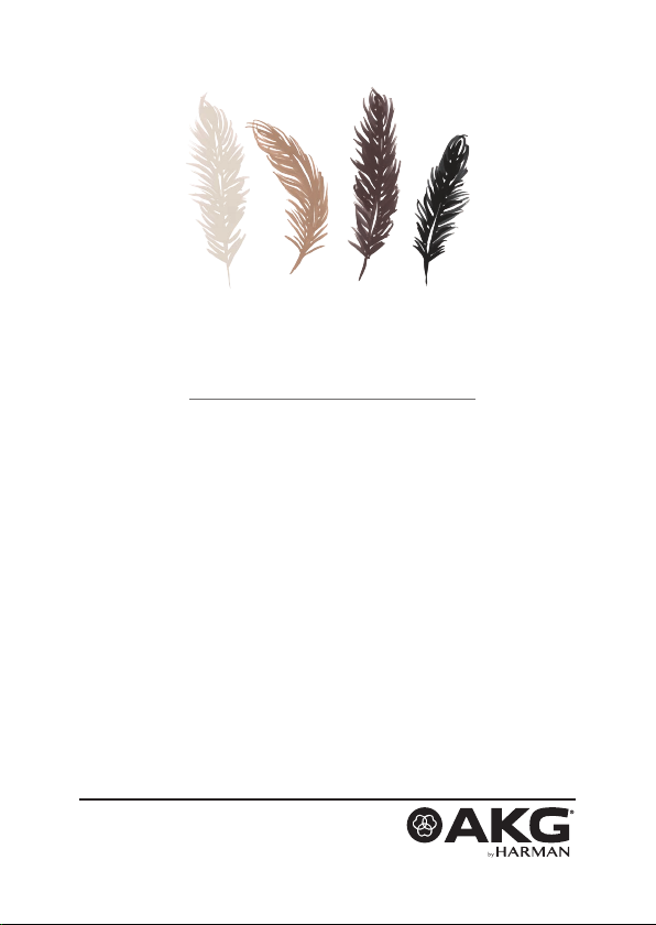
4 Lavaliermikrofone
Die Lavaliermikrofone LC81 MD sind Mikrofone mit nierenförmiger
Richtcharakteristik und sind in den Farben schwarz, weiß, beige
und cocoa erhältlich.
Die Lavaliermikrofone LC82 MD sind Mikrofone mit kugelförmiger
Richtcharakteristik und sind in den Farben schwarz, weiß, beige
und cocoa erhältlich.
Die Lavaliermikrofone in weiß und schwarz sind für die Montage
an der Kleidung vorgesehen und verfügen über eine Kabellänge
von 1 m.
Die Lavaliermikrofone in beige und cocoa sind zum Einschminken
im Kopfbereich vorgesehen und verfügen über eine Kabellänge
von 1,30 m.
Entsprechende Clips sind jeweils im Lieferumfang enthalten.
LAvALIERMIKROfONE
LC81 MD
LC82 MD
10
MM
1 Mikrofonkapsel
2 Ausnehmung für Clipspange (H1 und H2)
3 Mikrofonkabel
MICROLITE MANUAL 11
0,5
INCH
Abb. 1: LC81 MD (links) und LC82 MD (rechts)
1
10
2
MM
3
0,5
INCH
Page 12

LAvALIERMIKROfONE
4.1 Lieferumfang
Lieferumfang
Lavaliermikrofon
Mikrofon
Zubehör
LC81 MD
LC82 MD
Kontrollieren Sie, ob die Verpackung alle unten angeführten Teile
enthält.
Alle, für die Anwendung mit AKG Funksystemen benötigten
Zubehörteile sind bereits beigepackt. Adapterstecker für andere
FunksystemendenSieaufSeite36.
Die Mikrofone der MicroLite Serie sind Kondensatormikrofone und
benötigen daher eine Spannungsversorgung. Das entsprechende
Netzteil mit Phantomspeisung ist als optionales Zubehör erhältlich.
Siehe dazu Seite 36 ff.
Optionales Zubehör kann bei Bedarf nachgekauft werden.
• 1x LC81 MD (Lavaliermikrofon mit nierenförmiger
Richtcharakteristik in schwarz, weiß, beige oder cocoa)
• 1x LC82 MD (Lavaliermikrofon mit kugelförmiger
Richtcharakteristik in schwarz, weiß, beige oder cocoa)
4.2 Zubehör
Mikrofon inkl. Kabel 1 1
MDA1 Microdot Adapter AKG 1 1
WM81/WM82 Gitterkappe 2 2
W81/W82 Schaumstoff Windschutz 3 3
MUP81/MUP82 Make‑Up Schutz 3 3
LC81 MD
LC82 MD
schwarz/weiß
LC81 MD
LC82 MD
beige/cocoa
MICROLITE MANUAL12
Page 13
LAvALIERMIKROfONE
LC81 MD
LC82 MD
schwarz/weiß
LC81 MD
LC82 MD
beige/cocoa
H1 Magnetclip 1
H2 Krokoclip 1
H3 Kabelclip 1 1
Transportetui mit Sichtfenster 1 1
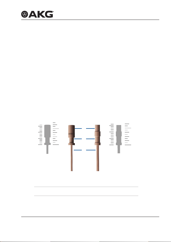
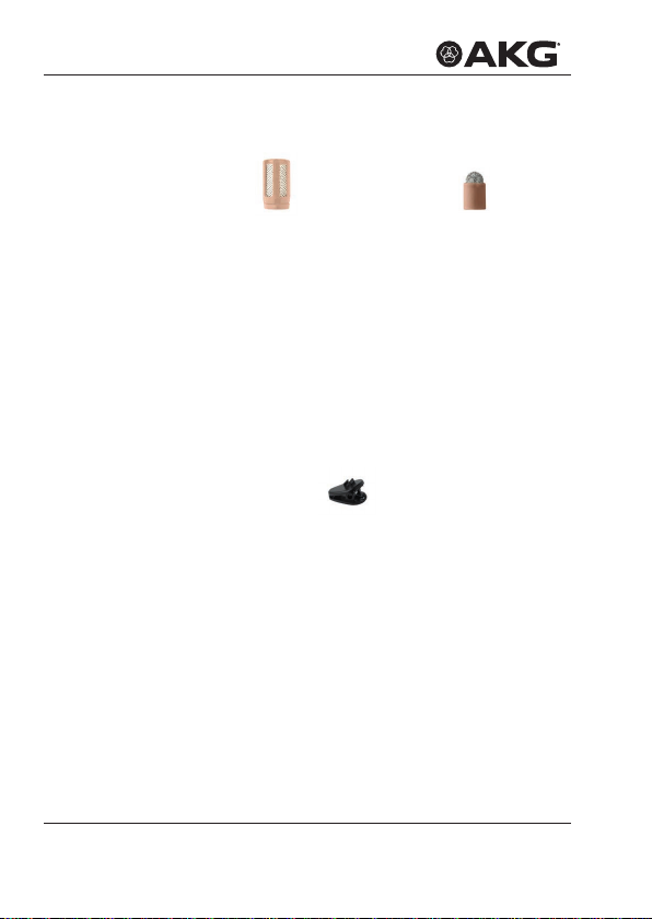
4.2.1 Gitterkappe
Abb. 2: WM81
Gitterkappe für LC81 MD
Die mitgelieferte Gitterkappe (WM81, WM82) besteht aus mehreren
Schichten verschiedenen Materials.
Die Gitterkappe dient dem Schutz vor Staub und Make‑Up. Zudem
schützt die Gitterkappe die Mikrofonmembran vor Wind‑ und
Poppgeräuschen.
Abb. 3: WM82
Gitterkappe für LC82 MD
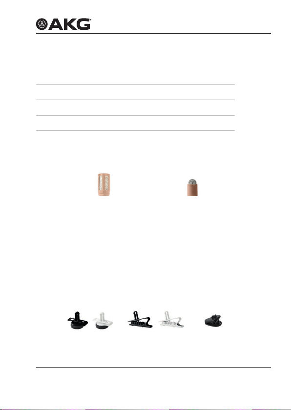
4.2.2 Lavalierclips
Die MicroLite Serie bietet drei verschiedene Lavalierclips zum
Befestigen des Mikrofons an der Kleidung:
Abb. 4: H1
Magnetclip
Abb. 5: H2
Krokoclip
Abb. 6: H3
Kabelclip
Gitterkappe
Lavalierclips
MICROLITE MANUAL 13
Page 14
LAvALIERMIKROfONE
Das Mikrofon wird am Gehäuse durch die Spange am Clip ange‑
bracht: Dadurch wird das Mikrofonkabel geschützt.
Der Kabelclip dient zum Befestigen des Kabels an der Kleidung.
Der Kabelclip dient der Zugentlastung des Mikrofonkabels.
Windschutz
Make-Up
Schutz
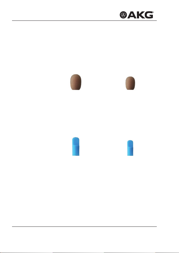
4.2.3 Windschutz
Abb. 7: W81
Windschutz für LC81 MD
Zum Abschirmen des Mikrofons vor Wind bei Aufnahmen im
Außenbereich wird über die Gitterkappe der Windschutz (W81,
W82) gestülpt, dadurch bleibt das Klangbild sauber und das
Mikrofon ist optimal geschützt.
Abb. 8: W82
Windschutz für LC82 MD
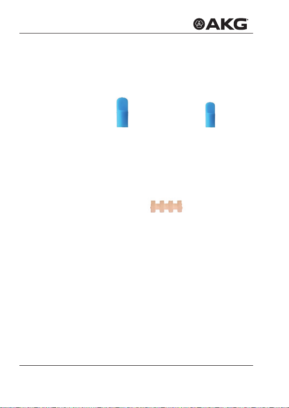
4.2.4 Make-Up Schutz
Abb. 9: MUP81
Make-Up Schutz für LC81 MD
Zum Schutz vor Make‑up während des Schminkvorgangs wird der
Make‑Up Schutz (MUP81, MUP82) auf das Mikrofon gesetzt.
Abb. 10: MUP82
Make-Up Schutz für LC82 MD
MICROLITE MANUAL14
Page 15
LAvALIERMIKROfONE
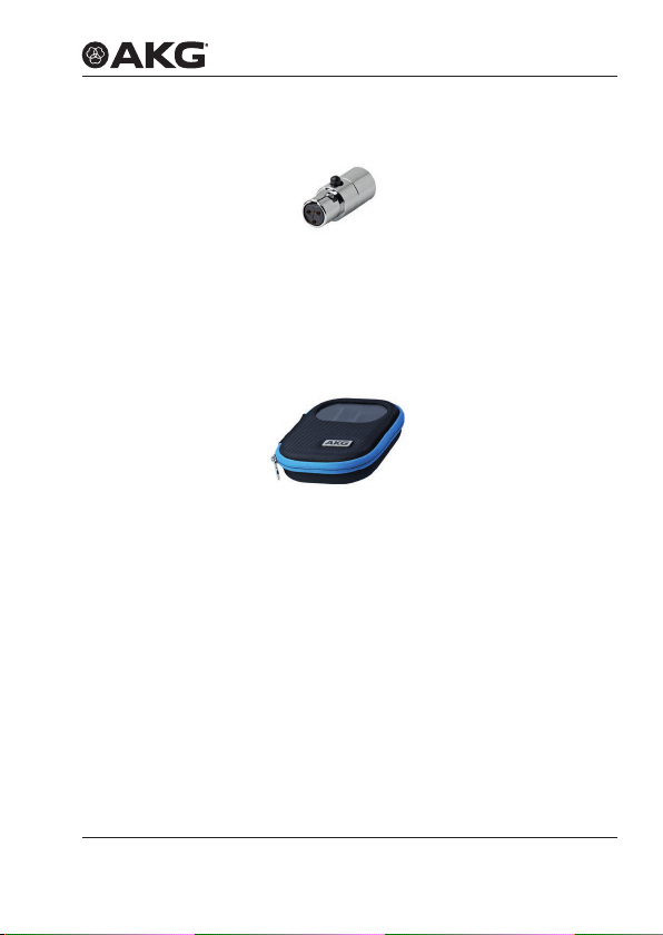
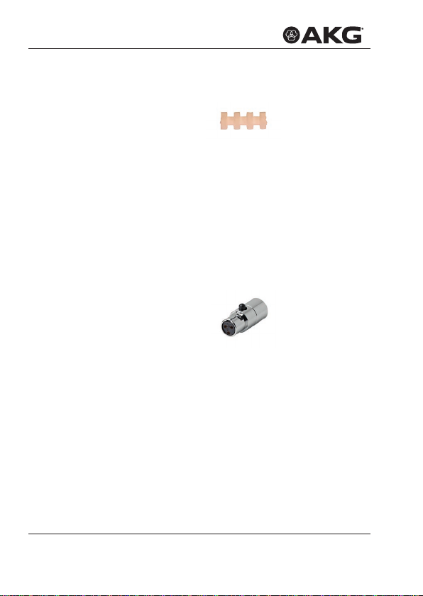
4.2.5 AKG Adapter-Stecker
Abb. 11: MDA1 AKG Adapter-Stecker
Der mitgelieferte Adapter‑Stecker MDA1 AKG verbindet die
Mikrofone der MicroLite Serie mit Taschensendern von AKG mit
3‑poligem Mini‑XLR Eingang.
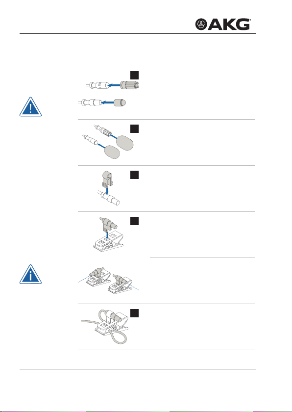
4.2.6 Etui mit Sichtfenster
Abb. 12: Etui mit Sichtfenster
Zum sicheren Verstauen des Lavaliermikrofons dient das mitgelie‑
ferte Etui. Das eingebaute Sichtfenster erlaubt jederzeit, die Farbe
bzw. die Art des Mikrofons zu überprüfen, ohne das Etui öffnen zu
müssen.
AKG Adapter-
Stecker
Etui
MICROLITE MANUAL 15
Page 16
LAvALIERMIKROfONE
Lavaliermikrofon
anbringen
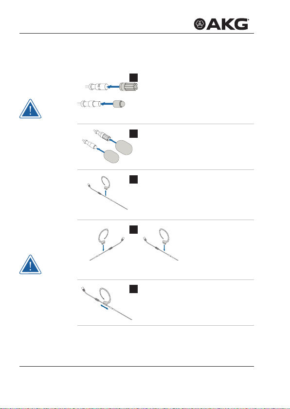
4.3 Lavaliermikrofon anbringen
Entnehmen Sie das Mikrofon dem
1
Etui und setzen Sie die Schutzkappe
auf die Mikrofonkapsel.
Achten Sie bei LC81 darauf, dass die
Schutzkappe die Schalleintrittslöcher
vollständig bedeckt!
Setzen Sie bei Bedarf den
2
Windschutz auf die Schutzkappe.
Befestigen Sie das Mikrofon an
3
der Ausnehmung unterhalb der
Mikrofonkapsel in der Spange des
Clips.
Drücken Sie die Beinchen der Spange
4
leicht zusammen und haken Sie sie in
eines der Löcher des Clips ein.
Hinweis:
Das Mikrofon kann je nach Bedarf
quer zum Clip bzw. in Richtung des
Clips eingehakt werden.
Fädeln Sie das Mikrofonkabel durch
5
die Kabelführungen des Clips und
bringen Sie das Mikrofon an ge‑
wünschter Stelle an.
MICROLITE MANUAL16
Page 17
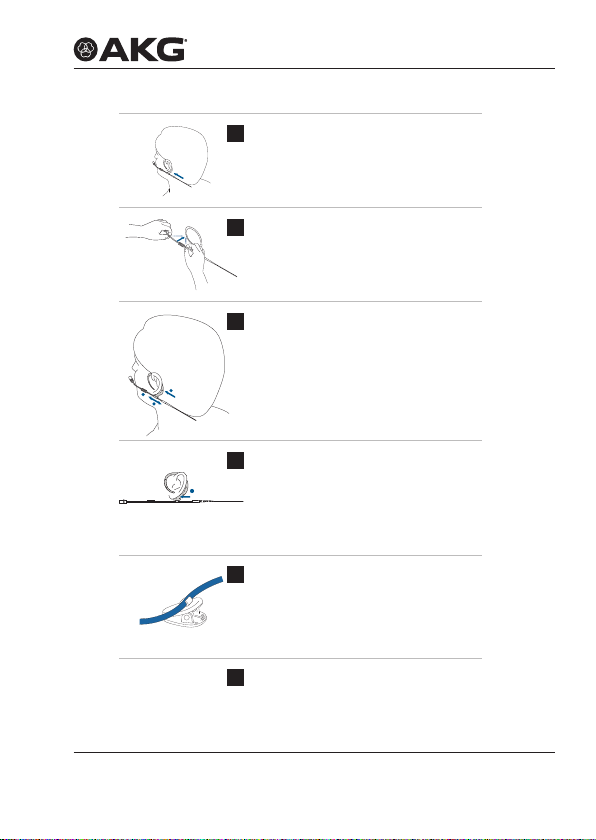
Zur Zugentlastung des Kabels
6
verwenden Sie den Kabelclip H3 (im
Lieferumfang von LCXX MD in beige
und cocoa enthalten):
Drücken Sie das Kabel in den
Kabelclip ein und bringen Sie den
Clip an der Kleidung an.
Schließen Sie das Mikrofon an. Siehe
7
dazu Seite 35 ff.
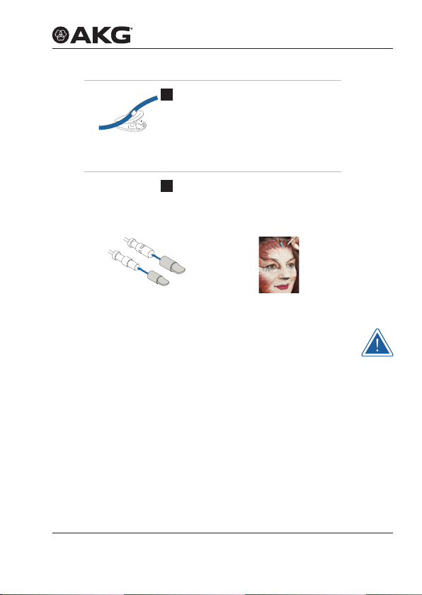
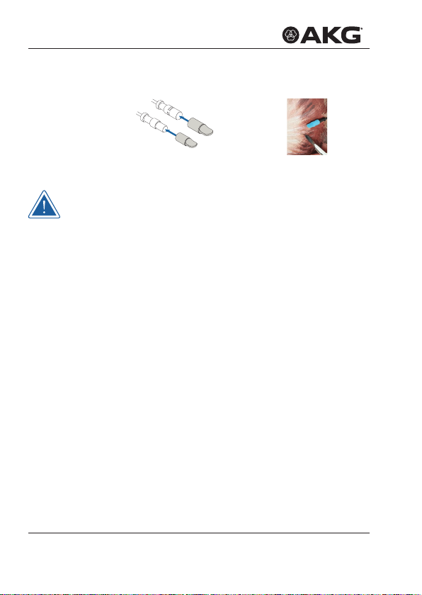
4.3.1 Make-Up Schutz anbringen
LAvALIERMIKROfONE
Abb. 13: Make-Up Schutz
anbringen
Wird das Mikrofon in die Maske mit eingebaut, setzen Sie den
Make‑Up Schutz während des Schminkvorgangs direkt auf die
Mikrofonkapsel!
Setzen Sie nach Entfernen des Make‑Up Schutzes die
Schutzkappe wieder auf! Bei Bedarf kann über die Schutzkappe
wiederum der Windschutz gestülpt werden.
Abb. 14: Lavaliermikrofon mit Make-Up
Schutz während Schminkvorgang
4.4 Anwendung des Mikrofons
Details zur Anwendung siehe ab Seite 38 ff.
4.5 Reinigung des Mikrofons
Details zur Reinigung der einzelnen Teile siehe ab Seite 43 ff.
MICROLITE MANUAL 17
Page 18
OHRBügELMIKROfONE
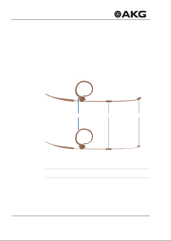
5 Ohrbügelmikrofone
EC81 MD
EC82 MD
Die Ohrbügelmikrofone EC81 MD sind Mikrofone mit nierenförmi‑
ger Richtcharakteristik und sind in den Farben beige und cocoa
erhältlich.
Die Ohrbügelmikrofone EC82 MD sind Mikrofone mit kugelförmi‑
ger Richtcharakteristik und sind in den Farben beige und cocoa
erhältlich.
1 Ohrbügel
2 Abtropfring
3 Mikrofonkapsel
31 2
Abb. 15: EC81 MD (oben) und EC82 MD (unten)
MICROLITE MANUAL18
Page 19

OHRBügELMIKROfONE
5.1 Lieferumfang
Kontrollieren Sie, ob die Verpackung alle unten angeführten Teile
enthält.
Alle, für die Anwendung mit AKG Funksystemen benötigten
Zubehörteile sind bereits beigepackt. Adapterstecker für andere
FunksystemendenSieaufSeite36.
Die Mikrofone der MicroLite Serie sind Kondensatormikrofone und
benötigen daher eine Spannungsversorgung. Das entsprechende
Netzteil mit Phantomspeisung ist als optionales Zubehör erhältlich.
Siehe dazu Seite 36 ff.
Optionales Zubehör kann bei Bedarf nachgekauft werden.
• 1x EC81 MD (Ohrbügelmikrofon mit nierenförmiger
Richtcharakteristik in beige oder cocoa)
• 1x EC82 MD (Ohrbügelmikrofon mit kugelförmiger
Richtcharakteristik in beige oder cocoa)
Lieferumfang
Ohrbügel-
mikrofon
Mikrofon
5.2 Zubehör
Mikrofon inkl. Kabel 1 1
MDA1 Microdot Adapter AKG 1 1
EC81 MD
beige/cocoa
EC82 MD
beige/cocoa
Zubehör
EC81 MD
EC82 MD
WM81/WM82 Gitterkappe 2 2
W81/W82 Schaumstoff Windschutz 3 3
MUP81/MUP82 Make‑Up Schutz 3 3
H3 Kabelclip 1 1
Transportetui mit Sichtfenster 1 1
MICROLITE MANUAL 19
Page 20
OHRBügELMIKROfONE
Gitterkappe
Kabelclip
5.2.1 Gitterkappe
Abb. 16: WM81
Gitterkappe für EC81 MD
Die mitgelieferte Gitterkappe (WM81, WM82) besteht aus mehreren
Schichten verschiedenen Materials.
Die Gitterkappe dient dem Schutz vor Staub und Make‑Up. Zudem
schützt die Gitterkappe die Mikrofonmembran vor Wind‑ und
Poppgeräuschen.
Abb. 17: WM82
Gitterkappe für EC82 MD
5.2.2 Kabelclip
Der Kabelclip dient zum Befestigen des Kabels an der Kleidung,
wodurch eine Zugentlastung des Mikrofonkabels erreicht wird.
Abb. 18: H3 Kabelclip
Das Mikrofon wird am Gehäuse durch die Spange am Clip ange‑
bracht: Dadurch wird das Mikrofonkabel geschützt.
MICROLITE MANUAL20
Page 21

OHRBügELMIKROfONE
5.2.3 Windschutz
Abb. 19: W81
Windschutz für EC81 MD
Zum Abschirmen des Mikrofons vor Wind bei Aufnahmen im
Außenbereich wird über die Gitterkappe der Windschutz (W81,
W82) gestülpt, dadurch bleibt das Klangbild sauber und das
Mikrofon ist optimal geschützt.
Abb. 20: W82
Windschutz für EC82 MD
5.2.4 Make-Up Schutz
Abb. 21: MUP81
Make-Up Schutz für EC81 MD
Zum Schutz vor Make‑up während des Schminkvorgangs wird der
Make‑Up Schutz (MUP81, MUP82) auf das Mikrofon gesetzt.
Abb. 22: MUP82
Make-Up Schutz für EC82 MD
Windschutz
Make-Up
Schutz
MICROLITE MANUAL 21
Page 22
OHRBügELMIKROfONE
Schweiß
schutz
AKG AdapterStecker
5.2.5 Schweißschutz
Abb. 23: Abtropfring
Die Ohrbügelmikrofone sind mit einem patentierten Abtropfring
ausgestattet, der am Drahtbügel angebracht ist.
Der Abtropfring erschwert das Eindringen von Schweiß und
Schminke in den Kapselbereich.
Dies verhindert, dass das Mikrofon verstopft wird, was zu dumpfem
KlangundgeringererEmpndlichkeitdesMikrofonsführenwürde.
5.2.6 AKG Adapter-Stecker
Abb. 24: MDA1 AKG Adapter-Stecker
Der mitgelieferte Adapter‑Stecker MDA1 AKG verbindet die
Mikrofone der MicroLite Serie mit Taschensendern von AKG mit
3‑poligem Mini‑XLR Eingang.
MICROLITE MANUAL22
Page 23

OHRBügELMIKROfONE
5.2.7 Etui mit Sichtfenster
Abb. 25: Etui mit Sichtfenster
Zum sicheren Verstauen des Lavaliermikrofons dient das mitgelie‑
ferte Etui. Das eingebaute Sichtfenster erlaubt jederzeit, die Farbe
bzw. die Art des Mikrofons zu überprüfen, ohne das Etui öffnen zu
müssen.
Etui
MICROLITE MANUAL 23
Page 24
OHRBügELMIKROfONE
Ohrbügelmikrofon
anbringen
5.3 Ohrbügelmikrofon anbringen
Entnehmen Sie das Mikrofon dem
1
Etui und setzen Sie die Schutzkappe
auf die Mikrofonkapsel.
Achten Sie bei LC81 darauf, dass die
Schutzkappe die Schalleintrittslöcher
vollständig bedeckt!
Setzen Sie bei Bedarf den
2
Windschutz auf die Schutzkappe.
Der Ohrbügel wird standardmä‑
3
ßig für das Tragen am linken Ohr
ausgeliefert.
Nehmen Sie den Ohrbügel ab, falls
Sie das Mikrofon am rechten Ohr
tragen möchten.
4
Achten Sie darauf, den Ohrbügel auf
denabgeachtenTeilzustecken.
Stellen Sie die Position des Mikrofons
5
ein, dazu den Ohrbügel entlang dem
abgeachtenDrahtteilverschieben.
Stecken Sie den
Ohrbügel auf der
gewünschten Seite
auf.
MICROLITE MANUAL24
Page 25
OHRBügELMIKROfONE
Legen Sie den Ohrbügel über das
6
Ohr, sodass die Verstärkung des
Ohrbügels hinter dem Ohrläppchen
eng anliegt.
Falls das Mikrofon zu locker sitzt,
7
nehmen Sie das Mikrofon nochmals
ab und biegen Sie den Drahtbügel
vorsichtig etwas nach innen.
Positionieren Sie das Mikrofon so,
8
dass die Mikrofonkapsel von ca.
1 cm Abstand auf den Mundwinkel
zeigt (1).
1
2
3
3
Achten Sie darauf, dass der
Schweißschutz auf der Haut anliegt
und nicht der Drahtbügel (2).
Achten Sie darauf, dass die
9
Verstärkung des Ohrbügels hinter
dem Ohrläppchen eng anliegt (3).
Fixieren Sie bei Bedarf den
Drahtbügel mit einem Tape an der
Wange.
Zur Zugentlastung des Kabels
10
verwenden Sie den mitgelieferten
Kabelclip H3:
Drücken Sie das Kabel in den
Kabelclip ein und bringen Sie den
Clip an der Kleidung an.
Schließen Sie das Mikrofon an. Siehe
11
dazu ab Seite 35 ff.
MICROLITE MANUAL 25
Page 26
OHRBügELMIKROfONE
Make-Up
Schutz
anbringen
Anwendung
Reinigung
5.3.1 Make-Up Schutz anbringen
Abb. 26: Make-Up Schutz
anbringen
Wird das Mikrofon in die Maske mit eingebaut, setzen Sie den
Make‑Up Schutz während des Schminkvorgangs direkt auf die
Mikrofonkapsel!
Setzen Sie nach Entfernen des Make‑Up Schutzes die
Schutzkappe wieder auf! Bei Bedarf kann über die Schutzkappe
wiederum der Windschutz gestülpt werden.
Abb. 27: Mikrofon mit Make-Up Schutz
während Schminkvorgang
5.4 Anwendung des Mikrofons
Details zur Anwendung siehe ab Seite 38 ff.
5.5 Reinigung des Mikrofons
Details zur Reinigung der einzelnen Teile siehe ab Seite 43 ff.
MICROLITE MANUAL26
Page 27
KOPfBügELMIKROfONE
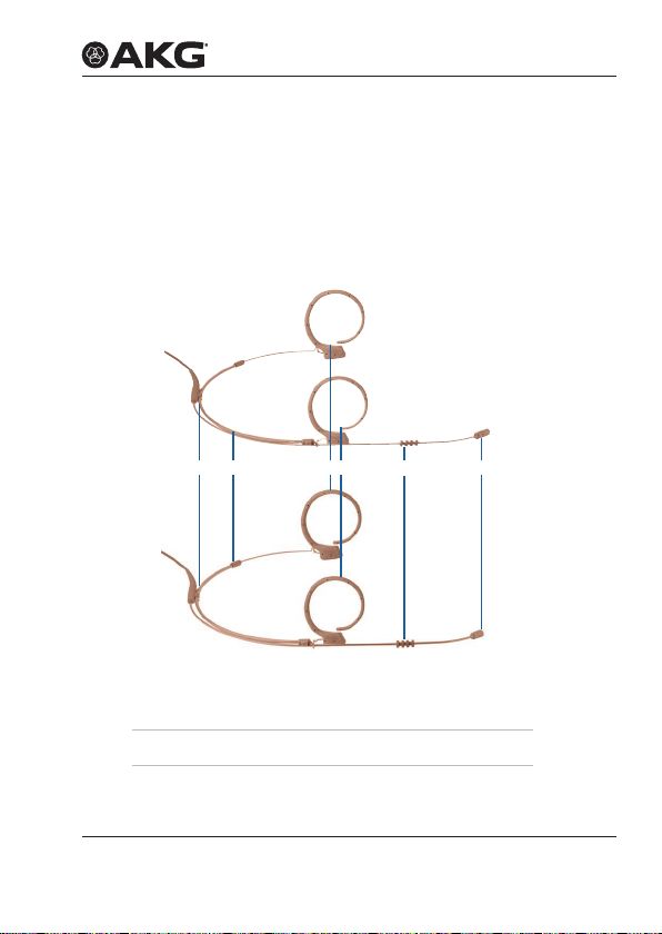
6 Kopfbügelmikrofone
Die Kopfbügelmikrofone HC81 MD sind Mikrofone mit nierenför‑
miger Richtcharakteristik und sind in den Farben beige und cocoa
erhältlich.
Die Kopfbügelmikrofone HC82 MD sind Mikrofone mit kugelför‑
miger Richtcharakteristik und sind in den Farben beige und cocoa
erhältlich.
HC81 MD
HC82 MD
321
Abb. 28: HC81 MD (oben) und HC82 MD (unten)
1 Zugentlastung für
Mikrofonkabel
2 Kopfbügel 5 Mikrofonkapsel
3 Ohrbügel
MICROLITE MANUAL 27
4
4 Abtropfring
5
Page 28

KOPfBügELMIKROfONE
6.1 Lieferumfang
Lieferumfang
Kopfbügelmikrofon
Mikrofon
Kontrollieren Sie, ob die Verpackung alle unten angeführten Teile
enthält.
Alle, für die Anwendung mit AKG Funksystemen benötigten
Zubehörteile sind bereits beigepackt. Adapterstecker für andere
FunksystemendenSieaufSeite36.
Die Mikrofone der MicroLite Serie sind Kondensatormikrofone und
benötigen daher eine Spannungsversorgung. Das entsprechende
Netzteil mit Phantomspeisung ist als optionales Zubehör erhältlich.
Siehe dazu Seite 36 ff.
Optionales Zubehör kann bei Bedarf nachgekauft werden.
• 1x HC81 MD (Kopfbügelmikrofon mit nierenförmiger
Richtcharakteristik in beige oder cocoa)
• 1x HC82 MD (Kopfbügelmikrofon mit kugelförmiger
Richtcharakteristik in beige oder cocoa)
Zubehör
HC81 MD
HC82 MD
6.2 Zubehör
HC81 MD
beige/cocoa
Mikrofon inkl. Kabel 1 1
MDA1 Microdot Adapter AKG 1 1
WM81/WM82 Gitterkappe 2 2
W81/W82 Schaumstoff Windschutz 3 3
MUP81/MUP82 Make‑Up Schutz 3 3
H3 Kabelclip 1 1
Transportetui mit Sichtfenster 1 1
beige/cocoa
MICROLITE MANUAL28
HC82 MD
Page 29
KOPfBügELMIKROfONE
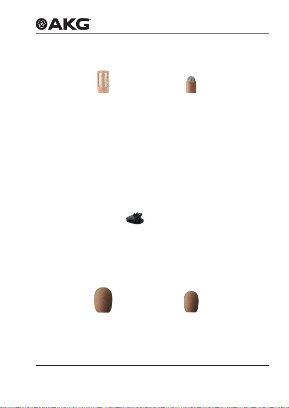
6.2.1 Gitterkappe
Abb. 29: WM81
Gitterkappe für EC81 MD
Die mitgelieferte Gitterkappe (WM81, WM82) besteht aus mehreren
Schichten verschiedenen Materials.
Die Gitterkappe dient dem Schutz vor Staub und Make‑Up. Zudem
schützt die Gitterkappe die Mikrofonmembran vor Wind‑ und
Poppgeräuschen.
Abb. 30: WM82
Gitterkappe für EC82 MD
6.2.2 Kabelclip
Der Kabelclip dient zum Befestigen des Kabels an der Kleidung,
wodurch eine Zugentlastung des Mikrofonkabels erreicht wird.
Abb. 31: H3 Kabelclip
Das Mikrofon wird am Gehäuse durch die Spange am Clip ange‑
bracht: Dadurch wird das Mikrofonkabel geschützt.
6.2.3 Windschutz
Abb. 32: W81
Windschutz für EC81 MD
Zum Abschirmen des Mikrofons vor Wind bei Aufnahmen im
Außenbereich wird über die Gitterkappe der Windschutz (W81,
Abb. 33: W82
Windschutz für EC82 MD
Gitterkappe
Kabelclip
Windschutz
MICROLITE MANUAL 29
Page 30
KOPfBügELMIKROfONE
W82) gestülpt, dadurch bleibt das Klangbild sauber und das
Mikrofon ist optimal geschützt.
Make-Up
Schutz
Schweiß
schutz
6.2.4 Make-Up Schutz
Abb. 34: MUP81
Make-Up Schutz für EC81 MD
Zum Schutz vor Make‑up während des Schminkvorgangs wird der
Make‑Up Schutz (MUP81, MUP82) auf das Mikrofon gesetzt.
Abb. 35: MUP82
Make-Up Schutz für EC82 MD
6.2.5 Schweißschutz
Abb. 36: Abtropfring
Die Kopfbügelmikrofone sind mit einem patentierten Abtropfring
ausgestattet, der am Drahtbügel angebracht ist.
Der Abtropfring erschwert das Eindringen von Schweiß und
Schminke in den Kapselbereich.
Dies verhindert, dass das Mikrofon verstopft wird, was zu dumpfem
KlangundgeringererEmpndlichkeitdesMikrofonsführenwürde.
MICROLITE MANUAL30
Page 31

KOPfBügELMIKROfONE
6.2.6 AKG Adapter-Stecker
Abb. 37: MDA1 AKG Adapter-Stecker
Der mitgelieferte Adapter‑Stecker MDA1 AKG verbindet die
Mikrofone der MicroLite Serie mit Taschensendern von AKG mit
3‑poligem Mini‑XLR Eingang.
6.2.7 Etui mit Sichtfenster
Abb. 38: Etui mit Sichtfenster
Zum sicheren Verstauen des Lavaliermikrofons dient das mitgelie‑
ferte Etui. Das eingebaute Sichtfenster erlaubt jederzeit, die Farbe
bzw. die Art des Mikrofons zu überprüfen, ohne das Etui öffnen zu
müssen.
AKG Adapter-
Stecker
Etui
MICROLITE MANUAL 31
Page 32

KOPfBügELMIKROfONE
Kopfbügelmikrofon
anbringen
6.3 Kopfbügelmikrofon anbringen
Entnehmen Sie das Mikrofon dem
1
Etui und setzen Sie die Schutzkappe
auf die Mikrofonkapsel.
Achten Sie bei LC81 darauf,
dass die Schutzkappe die
Schalleintrittslöcher vollständig
bedeckt!
Setzen Sie bei Bedarf den
2
Windschutz auf die Schutzkappe.
3
Stellen Sie die Position des
4
Mikrofons ein, dazu den Draht der
exiblenOhrbügelanderSchlinge
gleichmäßig bei beiden Seiten aus
dem Kopfbügel herausziehen.
Setzen Sie das Mikrofon von hinten
5
auf,dabeidieexiblenOhrbügel
über das Ohr legen, sodass die
Verstärkung jeweils hinter dem
Ohrläppchen anliegt.
Falls das Mikrofon zu locker sitzt,
6
nehmen Sie das Mikrofon nochmals
ab und biegen Sie den Drahtbügel
vorsichtig etwas nach innen.
Klappen Sie die
Ohrbügel senkrecht
nach oben, je
nachdem, ob Sie
das Mikrofon links
oder rechts tragen
möchten.
MICROLITE MANUAL32
Page 33

KOPfBügELMIKROfONE
Setzen Sie das Mikrofon wieder auf
7
und justieren Sie den Kopfbügel,
dazu den Bügel von hinten an den
Nacken drücken, bis er eng anliegt.
Positionieren Sie das Mikrofon so,
8
dass die Mikrofonkapsel von ca.
1 cm Abstand auf den Mundwinkel
zeigt (1).
3
2
1
3
Achten Sie darauf, dass der
Schweißschutz auf der Haut anliegt
und nicht der Drahtbügel (2).
Achten Sie darauf, dass die
9
Verstärkung des Ohrbügels hinter
dem Ohrläppchen eng anliegt (3).
Fixieren Sie bei Bedarf den
Drahtbügel mit einem Tape an der
Wange.
Wir empfehlen, die korrekte
Sitzposition des Kopfbügelmikrofons
vor einem Spiegel zu kontrollie‑
ren. Alternativ kann eine zweite
Person die korrekte Sitzposition
kontrollieren.
Zur Zugentlastung des Kabels
10
verwenden Sie den mitgelieferten
Kabelclip H3:
Drücken Sie das Kabel in den
Kabelclip ein und bringen Sie den
Clip an der Kleidung an.
Schließen Sie das Mikrofon an.
11
Siehe dazu ab Seite 35 ff.
MICROLITE MANUAL 33
Page 34

KOPfBügELMIKROfONE
6.4 Anwendung des Mikrofons
Details zur Anwendung siehe ab Seite 38 ff.
6.5 Reinigung des Mikrofons
Details zur Reinigung der einzelnen Teile siehe ab Seite 43 ff.
MICROLITE MANUAL34
Page 35

MIKROfON ANSCHLIESSEN
7 Mikrofon anschließen
7.1 Anschluss an AKG Funksysteme
Zum Anschluss an AKG
Funksysteme schrau‑
ben Sie den mitgelieferten
MDA1 AKG Adapter‑Stecker auf den
Microdot‑Stecker auf.
7.2 Anschluss an alternative Funksysteme
AKG garantiert nicht die Kompatibilität mit Funksystemen von
Fremdmarken und übernimmt diesbezüglich keine Haftung!
Entnehmen Sie nähere Informationen den Bedienungsanleitungen
der Funksysteme der jeweiligen Hersteller.
Zum Anschluss an alternative
1
Funksysteme tauschen Sie den
AKG Adapter‑Stecker gegen den
entsprechenden Adapter‑Stecker
aus.
Schrauben Sie den entsprechenden
2
Adapter auf. (Siehe dazu auf 36 ff)
Anschluss
AKG
Funk systeme
Alternative
Funk systeme
MICROLITE MANUAL 35
Page 36

MIKROfON ANSCHLIESSEN
7.3 Anschluss an herkömmliche Mischpulte via Kabel
7.4 Optionales Zubehör
7.4.1 Adapter-Stecker für alternative Systeme
Alle MicroLite Mikrofone sind mit einem Kabel mit Microdot‑Stecker
ausgestattet: Die Mikrofone sind somit mit einer Vielzahl von
Drahtlossystemen (AKG®, Audio‑Technica®, Beyerdynamic,
Lectrosonics®, Sennheiser® und Shure®) verwendbar.
Zum Anschluss an alternati‑
1
ve Mischpulte tauschen Sie
den AKG Adapter‑Stecker
gegen den entsprechenden
Phantomspeiseadapter (MDPA) aus.
Schließen Sie den
2
Phantomspeiseadapter (MDPA) an
(Siehe dazu auch auf Seite 36 ff).
Die Mikrofone der MicroLite
Serie sind Kondensatormikrofone
und benötigen daher eine
Spannungsversorgung.
Schließen Sie das Mikrofon
3
an einen symmetrischen
XLR‑Mikrofoneingang mit
Phantomspeisung an.
Schließen Sie das Kabel des
Mikrofoneingangs an das Mischpult
an.
1
1 Audio‑Technica®, Beyerdynamic, Lectrosonics®, Sennheiser® und Shure
sind eingetragene Warenzeichen der jeweiligen Hersteller
MICROLITE MANUAL36
®
Page 37

MIKROfON ANSCHLIESSEN
DieentsprechendenAdapterndenSienebenweiterem,optiona‑
lem Zubehör auf unserer Homepage www.akg.com.
MDA2 SEN1 MDA3 SEN2 MDA4 SHU MDA5 AT MDA6 BD MDA7 LEC
AKG garantiert nicht die Kompatibilität mit Funksystemen von
Fremdmarken und übernimmt diesbezüglich keine Haftung.
Abb. 39: Microdot-Adapter
7.4.2 Phantomspeiseadapter
Abb. 40: Phantomspeiseadapter (MDPA)
Für volle Flexibilität mit dem MicroLite Mikrofon kann auf eine
verkabelte Anwendung mit Hilfe des Phantomspeiseadapters
umgeschaltet werden.
Der Phantomadapter verfügt über:
• Microdot Eingang
• XLR Ausgang
• Low‑Cut Filter (zuschaltbar)
• Phasendrehung (umsteckbar per Jumper auf Platine, siehe
dazu Seite 39)
MICROLITE MANUAL 37
Page 38

ANWENduNg
Anwendung
Mikrofon
positionieren
Störungen
vermeiden
8 Anwendung
8.1 Allgemeines
Der große Vorteil eines Mikrofons, das an der Kleidung, am Kopf
oder in der Maske befestigt ist, besteht darin, dass der Abstand
zwischen Mikrofon und dem Mund des Anwenders immer gleich
bleibt.
Damit sind keine Pegelschwankungen zu befürchten.
Die Bewegungsfreiheit bleibt erhalten, die Hände bleiben frei.
8.2 Anwendungstipps
8.2.1 Positionierung des Mikrofons
Bei Mikrofonen mit nierenförmiger Richtcharakteristik muss bei der
Positionierung folgendes beachtet werden:
• Je näher das Mikrofon an der Schallquelle positioniert wird,
umso eher werden niedrige Frequenzen eingefangen.
• Mikrofone mit nierenförmiger Richtcharakteristik reagieren
sensibel auf Körper‑ und Windgeräusche.
8.2.2 Störungen durch Einstreuungen vermeiden
• Verlegen Sie zur Vermeidung von Störungen bzw.
Einstreuungen sämtliche Leitungen, speziell die der
Mikrofoneingänge, getrennt von Starkstromleitungen und
Netzleitungen.
• Bei Verlegung in Schächten oder Kabelkanälen achten Sie
darauf, die Übertragungsleitungen in einem separaten Kanal
unterzubringen.
MICROLITE MANUAL38
Page 39

8.2.3 Phase drehen
B
JPhase180
+
Jumper
Abb. 41: Phantomspeiseadapter
Die Phase des Signals kann über den Phantomspeiseadapter um
180° gedreht werden.
1) Schrauben Sie die Kreuzschlitzschraube am Gehäuse
Phantomspeiseadapters auf.
2) Nehmen Sie das Gehäuse ab.
3) Ziehen Sie den Jumper ab und stecken Sie ihn auf nur einen
Pin auf.
4) Setzen Sie das Gehäuse auf.
5) Drehen Sie die Schraube fest.
ANWENduNg
+
MICROLITE MANUAL 39
Page 40

ANWENduNg
8.3 Lavaliermikrofon anwenden
Sprachübertragung
Aufnahme-
und
Stützmikrofon
8.3.1 Sprachübertragung
min. 10 cm
Abb. 42: Sprachübertragung
Für eine optimale Sprachübertragung, befestigen Sie das Mikrofon
mit dem Krokoclip an der Kleidung. Positionien Sie das Mikrofon so
nahe wie möglich beim Mund des Redners.
Je geringer der Abstand zwischen dem Mikrofon und der
Schallquelle, umso geringer ist die Gefahr akustischer
Rückkopplungen und umso geringer ist der Raumanteil im
Aufnahmesignal.
8.3.2 Aufnahme- oder Stützmikrofon
Abb. 43: Mikrofon an Dekorationsteil befestigt
MICROLITE MANUAL40
Page 41

Befestigen Sie das Mikrofon mit dem Krokoclip oder dem
Magnetclip an einem geeigneten Dekorationsteil (z.B. Kulisse,
Hintergrund, Vorhang o.ä.).
ANWENduNg
8.3.3 Theater, Musical, Oper
Abb. 44: Sprach- und Gesangsübertragung
Befestigen Sie das Mikrofon in der Maske möglichst nahe beim
Mund.
8.3.4 Abnahme von Musikinstrumenten
Das Mikrofon kann an vielen Instrumenten (z.B.
Streichinstrumenten, Gitarre, Blasinstrumenten) befestigt werden.
DasichdasMikrofonsehrnaheanderSchallquellebendet,brau‑
chen Sie den Gain‑Regler am Mischpult nur wenig aufzudrehen.
Beim Einsatz in Beschallungsanlagen ist daher die
Rückkopplungsgefahr sehr gering.
Um die optimale Position des Mikrofons am Instrument zu ermit‑
teln, befestigen Sie das Mikrofon an verschiedenen Stellen am
Instrument und vergleichen Sie den Klang.
Bei Blasinstrumenten können Sie den mitgelieferten Windschutz
verwenden, um zu starke Blasgeräusche zu dämpfen.
Theater,
Musical, Oper
Abnahme
von Musik-
instrumenten
MICROLITE MANUAL 41
Page 42

ANWENduNg
Violine
Sprachübertragung
Violine
Abb. 45: Mikrofon zur Abnahme der Violine
Falls das Mikrofon nicht an der Violine selbst befestigt werden kann
oder darf, können Sie das Mikrofon mit einem Klebeband an der
Wange des Künstlers befestigen.
Alternativ können Sie ein Ohrbügel‑ oder Kopfbügelmikrofon
verwenden.
Diese Methode hat folgende Vorteile:
• DerKlangderViolinewirdnichtbeeinusst.
• Es besteht keine Gefahr, die Violine durch Klebeband o.ä. zu
beschädigen.
• Die Violine benötigt keinerlei Kabelverbindung.
8.4 Ohrbügelmikrofon und Kopfbügelmikrofon
8.4.1 Sprach- und Gesangsübertragung
Befestigen Sie das Mikrofon wie in Abschnitt 5 und 6.3 beschrie‑
ben.
Darauf achten, dass das Mikrofon von ca. 1 cm Entfernung auf den
Mundwinkel zeigt.
MICROLITE MANUAL42
Page 43

REINIguNg
8.4.2 Abnahme von Musikinstrumenten
Befestigen Sie das Mikrofon wie in Abschnitt 5 und 6.3 beschrie‑
ben.
Darauf achten, dass das Mikrofon von ca. 1 cm Entfernung auf den
Mundwinkel zeigt.
Bei Blasinstrumenten können Sie den mitgelieferten Windschutz
verwenden, um zu starke Blasgeräusche zu dämpfen.
9 Reinigung
Reinigen Sie folgende Teile, bevor Sie das Mikrofon im Etui
aufbewahren:
• Mikrofon
• Ohrbügel
• Schutzkappe
• Windschutz
• Make‑Up Schutz
Verstauen Sie das Mikrofon im Etui.
9.1 Mikrofon
Reinigen Sie das Gehäuse des Mikrofons mit einem feuchten Tuch.
Verwenden Sie keine Reinigungsmittel.
Abnahme
von Musik-
instrumenten
Mikrofon
MICROLITE MANUAL 43
Page 44

REINIguNg
Ohrbügel
Schutzkappe
9.2 Ohrbügel
9.3 Schutzkappe
Ziehen Sie beim Ohrbügelmikrofon
1
den Ohrbügel vom Draht.
Klappen Sie beim
2
Kopfbügelmikrofon die Ohrbügel
senkrecht nach innen.
Ziehen Sie die Ohrbügel an der
3
unteren Verstärkung vom Draht.
Waschen Sie die Ohrbügel in
4
60 bis 70 °C heißem Seifenwasser.
Lassen Sie die Ohrbügel vollständig
trocknen.
Schieben Sie die Ohrbügel wieder
auf den Draht.
Ziehen Sie die Schutzkappe vom
1
Mikrofon ab.
MICROLITE MANUAL44
Page 45

Waschen Sie die Schutzkappe in
2
lauwarmem Seifenwasser.
Lassen Sie die Schutzkappe
vollständig trocknen, bevor Sie sie
wieder verwenden.
REINIguNg
9.4 Windschutz
Ziehen Sie den Windschutz vom
1
Mikrofon ab.
Waschen Sie den Windschutz in
2
lauwarmem Seifenwasser.
Lassen Sie den Windschutz vollstän‑
dig trocknen, bevor Sie ihn wieder
verwenden.
9.5 Make-Up Schutz
Ziehen Sie den Make‑Up Schutz
1
vom Mikrofon ab.
Waschen Sie den Make‑Up Schutz
2
in lauwarmem Seifenwasser.
Lassen Sie den Make‑Up Schutz
vollständig trocknen, bevor Sie ihn
wieder verwenden.
MICROLITE MANUAL 45
Windschutz
Make-Up
Schutz
Page 46

TECHNISCHE dATEN
10 Technische Daten
XX81 MD
Frequenzgang
XX81 MD
Polardiagramm
XX81 MD
10.1 XX81 MD
10.1.1 Frequenzgang
Abb. 46: Frequenzgang XX81 MD
10.1.2 Polardiagramm
Abb. 47: Polardiagramm XX81 MD
MICROLITE MANUAL46
Page 47

TECHNISCHE dATEN
10.1.3 Spezikationen
Kapsel Kapsel mit Kondensatormikrofon
Richtcharakteristik Niere
Übertragungsbereich 20 bis 20 000 Hz (2 – 3 cm)
Empndlichkeit 13 mV/Pa
Geräuschpegelabstand 57 dB(A)
Grenzschalldruck
Klirrfaktor bei
1 000 Hz/120 dB
Elektrische Impedanz bei
1 000Hz
Eigenrauschen 35,5 mV
Erforderliche Spannung
(typische AKG Spannungs‑
versorgung)
Abmessungen Mikrofon (Kapsel):
Gewicht (inkl. Kabel) LC:
Anschluss 1 Microdot
Anschluss 2 alle gängigen Marken
145 dB
<1%
5 000 Ohm
5 V bei 4,5 kOhm, zweiadrige
Spannungsversorgung
∅ 4,4 mm
Länge: 8,5 mm
Kabel:
∅ 1,4 mm
5,3 g
EC:
7,6 g
HC:
11,7 g
Spezikation
XX81 MD
MICROLITE MANUAL 47
Page 48

TECHNISCHE dATEN
XX82 MD
Frequenzgang
XX82 MD
Polardiagramm
XX82 MD
10.2 XX82 MD
10.2.1 Frequenzgang
Abb. 48: Frequenzgang XX82 MD
10.2.2 Polardiagramm
Abb. 49: Polardiagramm XX82 MD
MICROLITE MANUAL48
Page 49

TECHNISCHE dATEN
10.2.3 Spezikationen
Kapsel Kapsel mit Kondensatormikrofon
Richtcharakteristik Kugel
Übertragungsbereich 20 bis 20 000 Hz (2 – 3 cm)
Empndlichkeit 15 mV/Pa
Geräuschpegelabstand 63 dB(A)
Grenzschalldruck
Klirrfaktor bei
1 000 Hz/120 dB
Elektrische Impedanz bei
1 000 Hz
Eigenrauschen 31,2 mV
Erforderliche Spannung
(typische AKG Spannungs‑
versorgung)
Abmessungen Mikrofon (Kapsel):
Gewicht (inkl. Kabel) LC:
Anschluss 1 Microdot
Anschluss 2 alle gängigen Marken
145 dB
<1%
5 000 Ohm
5 V bei 4,5 kOhm, zweiadrige
Spannungsversorgung
∅ 3,6 mm;
Länge: 7,2 mm
Kabel:
∅ 1,4 mm
5,3 g
EC:
7,6 g
HC:
11,7 g
Spezikation
XX82 MD
MICROLITE MANUAL 49
Page 50

fEHLERBEHEBuNg
11 Fehlerbehebung
Fehler Mögliche Ursache Abhilfe
Kein Ton Mischpult und/
oder Verstärkger
ausgeschaltet
Kanal‑Fader oder
Summenpegelregler
am Mischpult oder
Lautstärkeregler des
Verstärkers
steht auf Null
Mikrofon nicht
an Mischpult
oder Verstärker
angeschlossen
Kabelstecker nicht richtig
angesteckt
Kabel defekt Kabel überprüfen und falls
Keine Speisespannung Phantomspeisung einschalten.
Mischpult und/oder Verstärker
einschalten
Kanal‑Fader oder
Summenpegelregler
am Mischpult oder
Lautstärkeregler des
Verstärkers auf gewünschten
Pegel ein stellen
Mikrofon an Mischpult oder
Verstärker anschließen
Kabelstecker nochmals
anstecken
nötig ersetzen
Kabel überprüfen und falls
nötig ersetzen
MICROLITE MANUAL50
Page 51

fEHLERBEHEBuNg
Fehler Mögliche Ursache Abhilfe
Verzerrungen Gain‑Regler am
Auslöschung
mancher
Frequenzen
Lesen Sie zudem die Bedienungsanleitung des Senders und des
Empfängers!
Mischpult zu weit
aufgedreht
Mischpulteingang zu
empndlich
Phase verschoben Phase kann um 180°
Gain‑Regler zurückdrehen
Vorabschwächung zwischen
Mikrofonkabel und Eingang
stecken
verschoben werden
Siehe dazu Seite 39
MICROLITE MANUAL 51
Page 52

MICROLITE MANUAL52
Page 53

CONTENTS
1 GENERAL 56
1.1 Purpose of this user instructions 56
1.2 Storing this user instructions 56
1.3 Explanation of the symbols used 56
1.4 Correct use 57
1.5 Liability and warranty 57
1.6 Risk of damage 57
1.7 Safety and environment 58
1.7.1 Safety 58
1.8 Environment 59
2 DECLARATION OF CONFORMITY 59
3 MICROLITE: GENERAL DESCRIPTION 60
3.1 Introduction 60
3.2 Brief Description 60
3.3 MicroLite series variants 60
4 LAVALIER MICROPHONES 61
4.1 Package content 62
4.2 Accessories 63
4.2.1 Wire‑mesh grill 63
4.2.2 Lavalier clips 64
4.2.3 Wind screen 64
4.2.4 Make‑up cover 65
4.2.5 AKG adapter plug 65
4.2.6 Case with window 65
4.3 Attaching the lavalier microphone 66
4.3.1 Attaching the make‑up cover 67
4.4 Using the microphone 68
4.5 Cleaning the microphone 68
5 EAR HOOK MICROPHONE 69
5.1 Package content 70
5.2 Accessories 70
5.2.1 Wire‑mesh grill 71
5.2.2 Cable clip 71
5.2.3 Wind screen 71
5.2.4 Make‑up cover 72
5.2.5 Protection against sweat 72
MICROLITE MANUAL 53
Page 54

CONTENTS
5.2.6 AKG adapter plug 73
5.2.7 Case with window 73
5.3 Attaching the ear hook microphone 74
5.3.1 Attaching the make‑up cover 76
5.4 Using the microphone 76
5.5 Cleaning the microphone 76
6 HEADWORN MICROPHONES 77
6.1 Package content 78
6.2 Accessories 78
6.2.1 Wire‑mesh grill 79
6.2.2 Cable clip 79
6.2.3 Wind screen 79
6.2.4 Make‑up cover 80
6.2.5 Protection against sweat 80
6.2.6 AKG adapter plug 81
6.2.7 Case with window 81
6.3 Attaching the headworn microphone 82
6.4 Using the Microphone 84
6.5 Cleaning the microphone 84
7 CONNECTING THE MICROPHONE 84
7.1 Connecting the microphone to an AKG wireless system 84
7.2 Connecting the microphone to an alternative wireless system 84
7.3 Connection to conventional mixing console
7.4 Optional accessories 85
7.4.1 Adapter plug for alternative systems 85
7.4.2 Phantom power adapter 86
8 USE 87
8.1 General 87
8.2 Tips for use 87
8.2.1 Positioning the microphone 87
8.2.2 Avoiding disturbances from electrical interference 87
8.2.3 Rotating the phase 88
8.3 Using a lavalier microphone 89
8.3.1 Voice transmission 89
8.3.2 Recording microphone or spot microphone 90
8.3.3 Theater, musical or opera 90
using a cable 85
MICROLITE MANUAL54
Page 55

CONTENTS
8.3.4 Recording musical instruments 91
8.4 Ear hook microphone and headworn microphone 92
8.4.1 Transmitting voices or songs 92
8.4.2 Recording musical instruments 92
9 CLEANING 93
9.1 Microphone 93
9.2 Ear clip 93
9.3 Protective cap 94
9.4 Wind screen 95
9.5 Make‑up cover 95
10 TECHNICAL DATA 96
10.1 XX81 MD 96
10.1.1 Frequency response 96
10.1.2 Polar pattern 96
10.1.3 Specications 97
10.2 XX82 MD 98
10.2.1 Frequency response 98
10.2.2 Polar pattern 98
10.2.3 Specications 99
11 TROUBLESHOOTING 100
MICROLITE MANUAL 55
Page 56

gENERAL
1 General
Purpose of this
user instructions
Storing this
user instructions
Symbols used
1.1 Purpose of this user instructions
This user instructions is intended to enable you to:
• Operate the equipment safely
• Use the equipment correctly.
1.2 Storing this user instructions
Keep this user instructions in a safe place or store it electronically
in an easily accessible location.
Pass this user instructions on to subsequent owners.
This user instructions is an important part of the equipment.
1.3 Explanation of the symbols used
Describes useful information and application notes for
efcientoperationoftheequipment
Provides reference to more in‑depth information and
downloads online.
MICROLITE MANUAL56
Page 57

Includes information on the correct disposal of the
components described.
Describes instructions on how to dispose of packaging
correctly.
gENERAL
1.4 Correct use
The microphones from the MicroLite series are designed exclusi‑
vely for the transmission of sounds and voices.
1.5 Liability and warranty
AKG Acoustics GmbH accepts no liability or warranty for damage,
if
• Microphones from the MicroLite series are used for purposes
other than those described as intended use
• Damage is incurred due to incorrect operation
• Modicationsaremadetothemicrophones
• Documents are not kept up‑to‑date.
Correct use
Liability and
warranty
1.6 Risk of damage
Make sure that the piece of equipment your microphone will be
connectedtofulllsthesafetyregulationsimplementedinyour
countryandisttedwithagroundlead.
MICROLITE MANUAL 57
Page 58

gENERAL
1.7 Safety and environment
Safety
1.7.1 Safety
• Protect the equipment against
- Direct sunlight
- Theimpactofsignicantdustandhumidity
- Rain
- Vibrations or knocks.
• Do not spill liquids on the equipment.
• The equipment must only be used in dry rooms.
• The equipment must only be opened, serviced and repaired
by authorized personnel. The housing contains no user‑ser‑
viceable parts.
• Do not place the equipment near heat sources such as radi‑
ators,heatingducts,ampliers,etc.
• Do not expose the equipment to extreme forces and do not
pull on the cable.
• Only use the equipment for the applications described in this
user instructions. AKG cannot accept any liability for damages
resulting from improper handling or misuse.
MICROLITE MANUAL58
Page 59

dECLARATION Of CONfORMITy
1.8 Environment
• At the end of the product's service life, disconnect the
housing, electronics and cable from each other and discard
all components in accordance with applicable disposal
regulations.
• The packaging is recyclable. Dispose of the packaging via an
appropriate collection system provided for this purpose.
2 Declaration of Conformity
This product conforms to the standards listed in the Declaration
of Conformity. You can request the Declaration Of Conformity by
E‑Mail from sales@akg.com or download it from www.akg.com.
MICROLITE MANUAL 59
Page 60

MICROLITE: gENERAL dESCRIPTION
3 MicroLite: General description
Introduction
Brief
description
Versions
3.1 Introduction
Thank you for deciding to buy an AKG product. Read the user
instructions carefully before using the equipment and keep the user
instructions in a safe place so that you can refer to it at any time in
the future. We hope you enjoy the equipment and good luck!
3.2 Brief Description
The microphones from the MicroLite series are professional cardi‑
oid or omnidirectional condenser microphones. The microphones
arespecicallydesignedforuseinthefollowinghighendareas:
• Musicals
• Theater
• TV shows
• Presentations
The compact size ensures optimum comfort. Additionally, the
microphones feature the best sound quality and long service life.
The AKG MicroLite series is compatible with all common wireless
systems and can connect to an XLR cable.
3.3 MicroLite series variants
The following variants, each being cardioid and omnidirectional, are
available within the MicroLite series:
• Lavalier microphones (see pages 61 ff.)
• Ear hook microphones (see pages 69 ff.)
• Headworn microphones (see pages 77 ff.)
MICROLITE MANUAL60
Page 61

LAvALIER MICROPHONES
4 Lavalier microphones
The LC81 MD lavalier microphones are cardioid condenser micro‑
phones and are available in black, white, beige and cocoa.
The LC82 MD lavalier microphones are omnidirectional condenser
microphones and are available in black, white, beige and cocoa.
The lavalier microphones in black and white are designed to be
attached to clothing and have a 1 m cable.
The lavalier microphones in beige and cocoa are designed to be
used with make‑up in the head area and have a 1.3 m cable.
The corresponding clips for each of these microphones are inclu‑
ded in the package content.
LC81 MD
LC82 MD
10
MM
1 Microphone capsule
2 Recess for clip clasp (H1 and H2)
3 Microphone cable
MICROLITE MANUAL 61
0.5
INCH
Fig. 1: LC81 MD (left) and LC82 MD (right)
1
10
2
MM
3
0.5
INCH
Page 62

LAvALIER MICROPHONES
4.1 Package content
Lavalier
microphone
package
content
Microphone
Checktoensurethatthepackagecontainsallpartsspecied
below.
All accessory parts necessary for use with AKG wireless systems
are enclosed. Adapter plugs for other wireless systems can be
found on page 85.
The microphones in the MicroLite series are condenser micropho‑
nes. As a result, they require a power supply. The corresponding
power adapter with phantom power is available as an optional
accessory.
For more information, see pages 85 ff.
Optional accessories can be purchased later as required.
• 1x LC81 MD (lavalier cardioid condenser microphone in black,
white, beige or cocoa)
• 1x LC82 MD (lavalier omnidirectional condenser microphone
in black, white, beige or cocoa)
MICROLITE MANUAL62
Page 63

LAvALIER MICROPHONES
4.2 Accessories
LC81 MD
LC82 MD
black/white
Microphone including cable 1 1
MDA1 Microdot Adapter AKG 1 1
WM81/WM82 Wire‑mesh grill 2 2
W81/W82 Foam wind screen 3 3
MUP81/MUP82 Make‑up cover 3 3
H1 Magnet clip 1
H2 Crocodile clip 1
H3 Cable clip 1 1
Transport case with window 1 1
LC81 MD
LC82 MD
black/white
LC81 MD
LC82 MD
accessories
4.2.1 Wire-mesh grill
Fig. 2: WM81
Wire-mesh grill for LC81 MD
The supplied wire‑mesh grill (WM81, WM82) consists of several
layers of different materials.
The wire‑mesh grill is used as protection against dirt and make‑up.
Additionally, the wire‑mesh grill protects the microphone membra‑
ne from wind and pop noise.
Fig. 3: WM82
Wire-mesh grill for LC82 MD
Wire-mesh
grill
MICROLITE MANUAL 63
Page 64

LAvALIER MICROPHONES
Lavalier clips
Wind screen
4.2.2 Lavalier clips
The MicroLite series offers three different lavalier clips for attaching
the microphone to clothing:
Fig. 4: H1
Magnet clip
The microphone is attached to the housing by the clasp on the clip:
This helps ensure the microphone cable is protected.
The cable clip is used to fasten the cable to the article of clothing.
The cable clip is used for the strain relief of the microphone cable.
Fig. 5: H2
Crocodile clip
4.2.3 Wind screen
Fig. 7: W81
Wind screen for LC81 MD
The wind screen (W81, W82) is placed over the wire‑mesh grill to
shield the microphone from picking up wind outdoors. This ensures
the sound is clean and the microphone is optimally protected.
Fig. 8: W82
Wind screen for LC82 MD
Fig. 6: H3
Cable clip
MICROLITE MANUAL64
Page 65

LAvALIER MICROPHONES
4.2.4 Make-up cover
Fig. 9: MUP81
Make-up cover for LC81 MD
The make‑up cover (MUP81, MUP82) is placed on the microphone
to protect it during the make‑up application process.
Fig. 10: MUP82
Make-up cover for LC82 MD
4.2.5 AKG adapter plug
Fig. 11: MDA1 AKG adapter plug
The suppled MDA1 AKG adapter plug connects the MicroLite
series microphone to the AKG bodypack transmitter with a 3‑pin
Mini‑XLR input.
4.2.6 Case with window
Fig. 12: Case with window
The supplied case is used as a secure way of storing the lavalier
microphone. The built‑in window enables you to check the color or
type of microphone at any time without having to open the case.
Make-up
cover
AKG adapter
plug
Case
MICROLITE MANUAL 65
Page 66

LAvALIER MICROPHONES
Attaching
the lavalier
microphone
4.3 Attaching the lavalier microphone
Remove the microphone from the
1
case and place the protective cap on
the microphone capsule.
When attaching the LC81, make sure
the protective cap covers the sound
entry holes completely!
Place the wind screen on the protec‑
2
tive cap if necessary.
Fasten the microphone into the clip
3
clasp on the recess below the micro‑
phone capsule.
Gently push the legs of the clasp
4
together and clasp it into one of the
clip holes.
Note:
If necessary, the microphone can be
clasped laterally to the clip or in the
direction of the clip.
Thread the microphone cable through
5
the clip's cable glands and attach the
microphone in the desired position.
MICROLITE MANUAL66
Page 67

To support the cable, use the H3
6
cable clip (provided in the LCXX MD
package content, available in beige
or cocoa):
Press the cable into the cable clip
and attach the clip to the article of
clothing.
Connect the microphone. For more
7
information, see pages 84 ff.
4.3.1 Attaching the make-up cover
LAvALIER MICROPHONES
Fig. 13: Attaching
the make-up cover
If the microphone is built into the mask, place the make‑up cover
directly on the microphone capsule during the make‑up application
process!
Place the protective cap back on after removing the make‑up
cover! If necessary, the wind screen can be placed over the
protective cap.
Fig. 14: Lavalier microphone with
make-up cover during make-up
application
MICROLITE MANUAL 67
Page 68

LAvALIER MICROPHONES
4.4 Using the microphone
For details on use, see from page 87 ff.
4.5 Cleaning the microphone
For details on cleaning the individual parts, see from page 93 ff.
MICROLITE MANUAL68
Page 69

EAR HOOK MICROPHONE
5 Ear hook microphone
The EC81 MD ear hook microphones are cardioid condenser
microphones and are available in beige and cocoa.
The EC82 MD ear hook microphones are omnidirectional conden‑
ser microphones and are available in beige and cocoa.
Fig. 15: EC81 MD (top) and EC82 MD (bottom)
1 Ear clip
2 Moisture shield
3 Microphone capsule
EC81 MD
EC82 MD
31 2
MICROLITE MANUAL 69
Page 70

EAR HOOK MICROPHONE
5.1 Package content
Ear hook
microphone
package
content
Microphone
Checktoensurethatthepackagecontainsallpartsspecied
below.
All accessory parts necessary for use with AKG wireless systems
are enclosed. Adapter plugs for other wireless systems can be
found on page 85.
The microphones in the MicroLite series are condenser micropho‑
nes. As a result, they require a power supply. The corresponding
power adapter with phantom power is available as an optional
accessory.
For more information, see pages 85 ff.
Optional accessories can be purchased later as required.
• 1x EC81 MD (ear hook cardioid condenser microphone in
beige or cocoa)
• 1x EC82 MD (ear hook omnidirectional condenser microphone
in beige or cocoa)
EC81 MD
EC82 MD
accessories
5.2 Accessories
EC81 MD
beige/cocoa
EC82 MD
beige/cocoa
Microphone including cable 1 1
MDA1 Microdot Adapter AKG 1 1
WM81/WM82 Wire‑mesh grill 2 2
W81/W82 Foam wind screen 3 3
MUP81/MUP82 Make‑up cover 3 3
H3 Cable clip 1 1
Transport case with window 1 1
MICROLITE MANUAL70
Page 71

EAR HOOK MICROPHONE
5.2.1 Wire-mesh grill
Fig. 16: WM81
Wire-mesh grill for EC81 MD
The supplied wire‑mesh grill (WM81, WM82) consists of several
layers of different materials.
The wire‑mesh grill is used as protection against dirt and make‑up.
Additionally, the wire‑mesh grill protects the microphone membra‑
ne from wind and pop noise.
Fig. 17: WM82
Wire-mesh grill for EC82 MD
5.2.2 Cable clip
The cable clip is used to fasten the cable to the article of clothing,
which relieves stress on the microphone cable.
Fig. 18: H3 Cable clip
The microphone is attached to the housing by the clasp on the clip:
This helps ensure the microphone cable is protected.
5.2.3 Wind screen
Fig. 19: W81
Wind screen for EC81 MD
The wind screen (W81, W82) is placed over the wire‑mesh grill to
shield the microphone from picking up wind outdoors. This ensures
the sound is clean and the microphone is optimally protected.
Fig. 20: W82
Wind screen for EC82 MD
Wire-mesh
grill
Cable clip
Wind screen
MICROLITE MANUAL 71
Page 72

EAR HOOK MICROPHONE
Make-up
cover
Protection
against
sweat
5.2.4 Make-up cover
Fig. 21: MUP81
Make-up cover for EC81 MD
The make‑up cover (MUP81, MUP82) is placed on the microphone
to protect it during the make‑up application process.
Fig. 22: MUP82
Make-up cover for EC82 MD
5.2.5 Protection against sweat
Fig. 23: Moisture shield
The ear hook microphones are equipped with a patented moisture
shield that is attached to the wire frame.
The moisture shield prevents sweat and make‑up from penetrating
into the capsule area.
This prevents the microphone from being blocked, which could
lead to dull sound and lower microphone sensitivity.
MICROLITE MANUAL72
Page 73

EAR HOOK MICROPHONE
5.2.6 AKG adapter plug
Fig. 24: MDA1 AKG adapter plug
The suppled MDA1 AKG adapter plug connects the MicroLite
series microphone to the AKG bodypack transmitter with a 3‑pin
Mini‑XLR input.
5.2.7 Case with window
Fig. 25: Case with window
The supplied case is used as a secure way of storing the lavalier
microphone. The built‑in window enables you to check the color or
type of microphone at any time without having to open the case.
AKG adapter
plug
Case
MICROLITE MANUAL 73
Page 74

EAR HOOK MICROPHONE
Attaching
the ear hook
microphone
5.3 Attaching the ear hook microphone
Remove the microphone from the
1
case and place the protective cap on
the microphone capsule.
When attaching the LC81, make sure
the protective cap covers the sound
entry holes completely!
Place the wind screen on the protecti‑
2
ve cap if necessary.
The ear clip included in standard deli‑
3
very is to be worn on the left ear.
Remove the ear clip if you want to
wear the microphone on your right
ear.
4
Make sure you place the ear clip on
theattenedportion.
Adjust the position of the microphone
5
bymovingtheearclipalongtheat
part of the wire.
Attach the ear clip
on the desired side.
MICROLITE MANUAL74
Page 75

EAR HOOK MICROPHONE
Place the ear clip over your ear so
6
thattheearclip'sampliertssnugly
behind your earlobe.
If the microphone is too loose, remo‑
7
ve the microphone again and
carefully bend the wire frame
inwards.
Position the microphone so that the
8
microphone capsule is approximately
1 cm away from the corner of your
mouth (1).
1
2
3
3
Make sure the piece intended to
protect against sweat is positioned
against the skin and not against the
wire frame (2).
Makesuretheearclip'samplierts
9
snugly behind your earlobe (3).
If necessary, attach the wire frame to
your cheek using a piece of tape.
Use the supplied H3 cable clip as a
10
strain relief:
Press the cable into the cable clip
and attach the clip to the article of
clothing.
Connect the microphone. For more
11
information, see from page 84 ff.
MICROLITE MANUAL 75
Page 76

EAR HOOK MICROPHONE
Attaching the
make-up cover
Use
Cleaning
5.3.1 Attaching the make-up cover
Fig. 26: Attaching
the make-up cover
If the microphone is built into the mask, place the make‑up cover
directly on the microphone capsule during the make‑up application
process!
Place the protective cap back on after removing the make‑up
cover! If necessary, the wind screen can be placed over the
protective cap.
Fig. 27: Microphone with make-up
cover during make-up application
5.4 Using the microphone
For details on use, see from page 87 ff.
5.5 Cleaning the microphone
For details on cleaning the individual parts, see from page 93 ff.
MICROLITE MANUAL76
Page 77

HEAdWORN MICROPHONES
6 Headworn microphones
The HC81 MD headworn microphones are cardioid condenser
microphones and are available in beige and cocoa.
The HC82 MD headworn microphones are omnidirectional conden‑
ser microphones and are available in beige and cocoa.
HC81 MD
HC82 MD
321
Fig. 28: HC81 MD (top) and HC82 MD (bottom)
1 Strain relief for micropho‑
ne cable
2 Headset 5 Microphone capsule
3 Ear clip
MICROLITE MANUAL 77
4
4 Moisture shield
5
Page 78

HEAdWORN MICROPHONES
6.1 Package content
Headworn
microphone
package
content
Microphone
Checktoensurethatthepackagecontainsallpartsspecied
below.
All accessory parts necessary for use with AKG wireless systems
are enclosed. Adapter plugs for other wireless systems can be
found on page 85.
The microphones in the MicroLite series are condenser micropho‑
nes. As a result, they require a power supply. The corresponding
power adapter with phantom power is available as an optional
accessory.
For more information, see pages 85 ff.
Optional accessories can be purchased later as required.
• 1x HC81 MD (headworn cardioid condenser microphone in
beige or cocoa)
• 1x HC82 MD (headworn omnidirectional condenser micropho‑
ne in beige or cocoa)
HC81 MD
HC82 MD
accessories
6.2 Accessories
HC81 MD
beige/cocoa
Microphone including cable 1 1
MDA1 Microdot Adapter AKG 1 1
WM81/WM82 Wire‑mesh grill 2 2
W81/W82 Foam wind screen 3 3
MUP81/MUP82 Make‑up cover 3 3
H3 Cable clip 1 1
Transport case with window 1 1
beige/cocoa
MICROLITE MANUAL78
HC82 MD
Page 79

HEAdWORN MICROPHONES
6.2.1 Wire-mesh grill
Fig. 29: WM81
Wire-mesh grill for EC81 MD
The supplied wire‑mesh grill (WM81, WM82) consists of several
layers of different materials.
The wire‑mesh grill is used as protection against dirt and make‑up.
Additionally, the wire‑mesh grill protects the microphone membra‑
ne from wind and pop noise.
Fig. 30: WM82
Wire-mesh grill for EC82 MD
6.2.2 Cable clip
The cable clip is used to fasten the cable to the article of clothing,
which relieves stress on the microphone cable.
Fig. 31: H3 Cable clip
The microphone is attached to the housing by the clasp on the clip:
This helps ensure the microphone cable is protected.
6.2.3 Wind screen
Fig. 32: W81
Wind screen for EC81 MD
Fig. 33: W82
Wind screen for EC82 MD
Wire-mesh
grill
Cable clip
Wind screen
MICROLITE MANUAL 79
Page 80

HEAdWORN MICROPHONES
The wind screen (W81, W82) is placed over the wire‑mesh grill to
shield the microphone from picking up wind outdoors. This ensures
the sound is clean and the microphone is optimally protected.
Make-up cover
Protection
against sweat
6.2.4 Make-up cover
Fig. 34: MUP81
Make-up cover for EC81 MD
The make‑up cover (MUP81, MUP82) is placed on the microphone
to protect it during the make‑up application process.
Fig. 35: MUP82
Make-up cover for EC82 MD
6.2.5 Protection against sweat
Fig. 36: Moisture shield
The headworn microphones are equipped with a patented moisture
shield that is attached to the wire frame.
The moisture shield prevents sweat and make‑up from penetrating
into the capsule area.
This prevents the microphone from being blocked, which could
lead to dull sound and lower microphone sensitivity.
MICROLITE MANUAL80
Page 81

HEAdWORN MICROPHONES
6.2.6 AKG adapter plug
Fig. 37: MDA1 AKG adapter plug
The suppled MDA1 AKG adapter plug connects the MicroLite
series microphone to the AKG bodypack transmitter with a 3‑pin
Mini‑XLR input.
6.2.7 Case with window
Fig. 38: Case with window
The supplied case is used as a secure way of storing the lavalier
microphone. The built‑in window enables you to check the color or
type of microphone at any time without having to open the case.
AKG adapter
plug
Case
MICROLITE MANUAL 81
Page 82

HEAdWORN MICROPHONES
Attaching the
headworn
microphone
6.3 Attaching the headworn microphone
Remove the microphone from the
1
case and place the protective cap
on the microphone capsule.
When attaching the LC81, make
sure the protective cap covers the
sound entry holes completely!
Place the wind screen on the protec‑
2
tive cap if necessary.
3
Adjust the position of the micropho‑
4
ne by grasping the loop and pulling
the ear clip wire the same distance
out of the headset on both sides.
Place the microphone on your head
5
frombehind,positioningtheexible
ear clips over your ears so that the
eachoftheampliersarebehind
your earlobe.
If the microphone is too loose,
6
remove the microphone again
and carefully bend the wire frame
inwards.
Fold the ear clip
upwards in a vertical
direction depending
on whether you want
to wear the micro‑
phone on the left or
the right.
MICROLITE MANUAL82
Page 83

HEAdWORN MICROPHONES
Place the microphone on your head
7
again and adjust the headset by
pushing the clip toward your neck
frombehinduntilittssnugly.
Position the microphone so that the
8
microphone capsule is approxima‑
tely 1 cm away from the corner of
your mouth (1).
3
2
1
3
Make sure the piece intended to
protect against sweat is positioned
against the skin and not against the
wire frame (2).
Makesuretheearclip'samplierts
9
snugly behind your earlobe (3).
If necessary, attach the wire frame
to your cheek using a piece of tape.
We recommend using a mirror to
check the correct position of the
headworn microphone. Alternatively,
a second person can help ensure
the headworn microphone is in the
correct position.
Use the supplied H3 cable clip as a
10
strain relief:
Press the cable into the cable clip
and attach the clip to the article of
clothing.
Connect the microphone. For more
11
information, see from page 84 ff.
MICROLITE MANUAL 83
Page 84

CONNECTINg THE MICROPHONE
6.4 Using the Microphone
For details on use, see from page 87 ff.
6.5 Cleaning the microphone
For details on cleaning the individual parts, see from page 93 ff.
Connection
7 Connecting the microphone
AKG
wireless
system
Alternative
wireless
systems
7.1 Connecting the microphone to an AKG wireless system
Screw the supplied MDA1 AKG ad‑
apter plug into the Microdot plug
to connect it to an AKG wireless
system.
7.2 Connecting the microphone to an alternative wireless system
AKG makes no guarantee of compatibility to third‑party wireless
systems and assumes no liability in this respect!
For more information, refer to the user instructions from the respec‑
tive wireless system manufacturer.
Replace the AKG adapter plug with
1
the corresponding adapter plug to
connect it to an alternative wireless
system.
Screw on the corresponding adap‑
2
ter. (For more information, see from
page 85 ff)
MICROLITE MANUAL84
Page 85

CONNECTINg THE MICROPHONE
7.3 Connection to conventional mixing console using a cable
Replace the AKG adapter plug with
1
the corresponding phantom power
adapter (MDPA) to connect it to an
alternative mixing console.
Connect the phantom power adapter
2
(MDPA) (for more information, see
from page 85 ff).
The microphones in the MicroLite
series are condenser microphones.
As a result, they require a power
supply.
Connect the microphone to a
3
balanced XLR microphone input with
phantom power.
Connect the microphone input cable
to the mixing console.
7.4 Optional accessories
7.4.1 Adapter plug for alternative systems
All MicroLite microphones are equipped with a cable and a
Microdot plug: This ensures the microphones can be used with
a wide variety of wireless systems (AKG®, Audio‑Technica®,
Beyerdynamic, Lectrosonics®, Sennheiser® and Shure®).
1
1 Audio‑Technica®, Beyerdynamic, Lectrosonics®, Sennheiser® and Shure
are registered trademarks of the respective manufacturers
®
MICROLITE MANUAL 85
Page 86

CONNECTINg THE MICROPHONE
In addition to a wide variety of optional accessories, the correspon‑
ding adapters can be found on our website www.akg.com.
MDA2 SEN1 MDA3 SEN2 MDA4 SHU MDA5 AT MDA6 BD MDA7 LEC
AKG makes no guarantee of compatibility to third‑party wireless
systems and assumes no liability in this respect.
Fig. 39: Microdot Adapter
7.4.2 Phantom power adapter
Fig. 40: Phantom power adapter (MDPA)
ToensurecompleteexibilitywiththeMicroLitemicrophone,
users can switch to a wired application using the phantom power
adapter.
The phantom adapter is equipped with:
• Microdot input
• XLR output
• Lowcutlter(switchable)
• Phase rotation (can be plugged in via a jumper on the board,
for more information, see page 88)
MICROLITE MANUAL86
Page 87

uSE
8 Use
8.1 General
The major advantage of a microphone that is attached to an article
of clothing, on the user's head or in their mask is that the distance
between the microphone and the user's mouth is always the same.
This ensures there is no need to worry about the microphone level
uctuating.
The freedom of movement is preserved and hands remain free.
8.2 Tips for use
8.2.1 Positioning the microphone
The following must be taken into consideration when positioning
cardioid condenser microphones:
• The closer the microphone is positioned to the sound source,
the more low frequencies are captured.
• Cardioid condenser microphones are sensitive to body noises
and wind noises.
8.2.2 Avoiding disturbances from electrical interference
• To avoid hum or interference, route all audio lines, particularly
those connected to the microphone inputs, away from power
lines of any type.
• If you use cable ducts, be sure to use separate ducts for the
audio lines.
Use
Positioning
the micro-
phone
Avoiding
interference
MICROLITE MANUAL 87
Page 88

uSE
8.2.3 Rotating the phase
B
+
Fig. 41: Phantom power adapter
The signal phase can be rotated by 180° using the phantom power
adapter.
1) Screw the Phillips‑head screw into the phantom adapter's
housing.
2) Remove the housing.
3) Remove the jumper and plug it into only one pin.
4) Put the housing on.
5) Tighten the screws.
+
JPhase180
Jumper
MICROLITE MANUAL88
Page 89

8.3 Using a lavalier microphone
uSE
8.3.1 Voice transmission
min. 10 cm
Fig. 42: Voice transmission
Fasten the microphone to a piece of clothing with the crocodile clip
to ensure optimal voice transmission. Position the microphone as
close as possible to the speaker's mouth.
The smaller the distance between the microphone and the sound
source, the lower the risk of acoustic feedback and the less room
noise will be picked up in the audio signal.
Voice
transmission
MICROLITE MANUAL 89
Page 90

uSE
Recording
microphone
and spot
microphone
Theater,
musical or
opera
8.3.2 Recording microphone or spot microphone
Fig. 43: Microphone attached to a decorative piece
Fasten the microphone to a suitable decorative piece using the
crocodile clip or the magnet clip (e.g. a backdrop, background or
curtain).
8.3.3 Theater, musical or opera
Fig. 44: Transmitting voices or songs
Attach the microphone in the mask as close as possible to the
mouth.
MICROLITE MANUAL90
Page 91

uSE
8.3.4 Recording musical instruments
The microphone can be attached to a variety of different instru‑
ments (e.g. string instruments, guitars, wind instruments).
You only need to rotate the gain controller on the mixing console
slightly because the microphone is located very close to the sound
source.
For this reason, feedback occurs only in very low levels in PA
systems.
Attach the microphone to different positions on the instrument
and compare the sound to determine the optimal position of the
microphone on an instrument.
You can use the supplied wind screen on wind instruments to
dampen the sounds of rushing air.
Violin
Fig. 45: Microphone for recording the violin
The microphone can be fastened to the performer's cheek using a
piece of tape if the microphone cannot or should not be attached
to the violin itself.
Alternatively, you can use the ear clip or the headworn microphone.
Recording
musical
instruments
Violin
MICROLITE MANUAL 91
Page 92

uSE
This method offers the following advantages:
• Thesoundoftheviolinisnotinuenced.
• There is no risk of damaging the violin by using tape.
• The violin does not require a cable connection.
8.4 Ear hook microphone and headworn microphone
Voice
transmission
Recording
musical
instruments
8.4.1 Transmitting voices or songs
Attach the microphone as described in section 5 and 6.3.
Make sure that the microphone is approximately 1 cm away from
the corner of your mouth.
8.4.2 Recording musical instruments
Attach the microphone as described in section 5 and 6.3.
Make sure that the microphone is approximately 1 cm away from
the corner of your mouth.
You can use the supplied wind screen on wind instruments to
dampen the sounds of rushing air.
MICROLITE MANUAL92
Page 93

9 Cleaning
Clean the following parts before you store the microphone in the
case:
• Microphone
• Ear clip
• Protective cap
• Wind screen
• Make‑up cover
Stow the microphone in the case.
CLEANINg
9.1 Microphone
Use a damp cloth to clean the microphone housing.
Do not use any cleaning agents.
9.2 Ear clip
Pull the ear clip from the wire on the
1
ear hook microphone.
Fold the ear clip vertically inward on
2
the headworn microphone.
MICROLITE MANUAL 93
Microphone
Ear clip
Page 94

CLEANINg
Pull the ear clip from the wire on the
3
loweramplier.
Wash the ear clip in hot, soapy
4
water (60 to 70 °C).
Allow the ear clip to dry completely.
Push the ear clip back on to the
wire.
Protective
cap
9.3 Protective cap
Remove the protective cap from the
1
microphone.
Wash the protective cap in warm,
2
soapy water.
Allow the protective cap to dry com‑
pletely before using it again.
MICROLITE MANUAL94
Page 95

CLEANINg
9.4 Wind screen
9.5 Make-up cover
Remove the wind screen from the
1
microphone.
Wash the wind screen in warm,
2
soapy water.
Allow the wind screen to dry com‑
pletely before using it again.
Remove the make‑up cover from the
1
microphone.
Wash the make‑up cover in warm,
2
soapy water.
Allow the make‑up cover to dry
completely before using it again.
Wind screen
Make-up cover
MICROLITE MANUAL 95
Page 96

TECHNICAL dATA
10 Technical data
XX81 MD
XX81 MD
frequency
response
XX81 MD
polar pattern
10.1 XX81 MD
10.1.1 Frequency response
Fig. 46: XX81 MD frequency response
10.1.2 Polar pattern
Fig. 47: XX81 MD polar pattern
MICROLITE MANUAL96
Page 97

TECHNICAL dATA
10.1.3 Specications
Capsule Capsule with condenser microphone
Directivity pattern Cardioid
Frequency range 20 to 20,000 Hz (2 – 3 cm)
Sensitivity 13 mV/Pa
Signal‑to‑noise ratio 57 dB(A)
Max. SPL
(sound pressure level)
THD (total harmo‑
nic distortion) at
1,000 Hz/120 dB
Electric impedance at
1,000 Hz
Equivalent noise level 35.5 mV
Required voltage (typical
AKG power requirement)
Dimensions
Weight (including cable) LC:
Connection 1 Microdot
Connection 2 All common brands
145 dB
<1%
5,000 ohms
5 V at 4.5 kOhm, two‑wire power
requirement
Microphone (capsule):
∅ 4.4 mm
Length: 8.5 mm
Cable:
∅ 1.4 mm
5.3 g
EC:
7.6 g
HC:
11.7 g
XX81 MD
specication
MICROLITE MANUAL 97
Page 98

TECHNICAL dATA
XX82 MD
XX82 MD
frequency
response
XX82 MD
polar pattern
10.2 XX82 MD
10.2.1 Frequency response
Fig. 48: XX82 MD frequency response
10.2.2 Polar pattern
Fig. 49: XX82 MD polar pattern
MICROLITE MANUAL98
Page 99

TECHNICAL dATA
10.2.3 Specications
Capsule Capsule with condenser microphone
Directivity pattern Omnidirectional
Frequency range 20 to 20,000 Hz (2 – 3 cm)
Sensitivity 15 mV/Pa
Signal‑to‑noise ratio 63 dB(A)
Max. SPL
(sound pressure level)
THD (total harmo‑
nic distortion) at
1,000 Hz/120 dB
Electric impedance at
1,000 Hz
Equivalent noise level 31.2 mV
Required voltage (typical
AKG power requirement)
Dimensions
Weight (including cable) LC:
Connection 1 Microdot
Connection 2 All common brands
145 dB
<1%
5,000 ohms
5 V at 4.5 kOhm, two‑wire power
requirement
Microphone (capsule):
∅ 3.6 mm;
Length: 7.2 mm
Cable:
∅ 1.4 mm
5.3 g
EC:
7.6 g
HC:
11.7 g
XX82 MD
specication
MICROLITE MANUAL 99
Page 100

TROuBLESHOOTINg
11 Troubleshooting
Problem Possible cause Remedy
No sound Power to mixing
console and/or
amplierisoff
Channel fader or
master level controller
on the mixing console
or volume control on
amplierisatzero
Microphone is not
connected to mixing
consoleoramplier
Cable connector not
plugged in correctly
The cable is defective Check the cable and replace if
No supply voltage Switch on phantom power.
Switch on power to mixing console
oramplier
Set channel fader or master level
controller on mixing console or
volumecontrolonamplierto
desired level
Connect microphone to mixing
consoleoramplier
Plug in cable connector again
necessary
Check the cable and replace if
necessary
MICROLITE MANUAL100
 Loading...