

Page 1
GB 40 FLEXX
BEDIENUNGSANLEITUNG . .S. 2
Bitte vor Inbetriebnahme des Gerätes lesen!
USER INSTRUCTIONS . . . . . . . .p. 10
Please read the manual before using the equipment!
MODE D’EMPLOI . . . . . . . . . . . . . . . .p. 18
Veuillez lire cette notice avant d’utiliser le système!
ISTRUZIONI PER L’USO . . . . .p. 26
Prima di utilizzare l’apparecchio, leggere il manuale!
MODO DE EMPLEO . . . . . . . . . . . .p. 34
¡Sirvase leer el manual antes de utilizar el equipo!
INSTRUÇÕES DE USO . . . . . . . .p. 42
Favor leia este manual antes de usar o equipamento!
guitarbug
Page 2

Inhaltsverzeichnis
Seite
1 Sicherheit und Umwelt........................................................................3
1.1 Sicherheit..................................................................................3
1.2 Umwelt .....................................................................................3
2 Beschreibung ......................................................................................3
2.1 Einleitung ..................................................................................3
2.2 Lieferumfang .............................................................................3
2.3
Optionales Zubehör....................................................................3
2.4 Beschreibung ............................................................................3
2.5 Bedienelemente.........................................................................4
3 Inbetriebnahme...................................................................................5
3.1 Batterie einlegen/tauschen und testen ........................................5
3.2 Betrieb mit Akku ........................................................................6
4 Anwendung .........................................................................................7
4.1 Sender befestigen......................................................................7
2
Seite
4.2 Pegel einstellen .........................................................................7
4.3 Instrumente mit versenkter Ausgangsbuchse...............................7
4.4 Sender stabilisieren ...................................................................8
4.5 Fehlerbehebung.........................................................................8
5 Reinigung............................................................................................8
6 Technische Daten ................................................................................9
GB 40 FLEXX guitarbug
Page 3
!
L
1 Sicherheit und Umwelt
1.1 Sicherheit
1. Setzen Sie das Gerät nicht direkter Sonneneinstrahlung, starker Staub- und Feuchtigkeitseinwirkung, Regen, Vibrationen oder Schlägen
aus.
1.2 Umwelt
1. Entsorgen Sie verbrauchte Batterien und Akkus
immer gemäß den jeweils geltenden
Entsorgungsvorschriften. Werfen Sie Batterien
oder Akkus weder ins Feuer (Explosionsgefahr)
noch in den Restmüll.
2. Wenn Sie das Gerät verschrotten, entfernen Sie
die Batterien bzw. Akkus, trennen Sie Gehäuse,
Elektronik und Kabel und entsorgen Sie alle
Komponenten gemäß den dafür geltenden Entsorgungsvorschriften.
3. Die Verpackung ist recyclierbar. Entsorgen Sie
die Verpackung in einem dafür vorgesehenen
Sammelsystem.
GB 40 FLEXX guitarbug
2 Beschreibung
2.1 Einleitung
Vielen Dank, dass Sie sich für ein Produkt aus dem
Hause AKG entschieden haben. Bitte lesen Sie
die Bedienungsanleitung aufmerksam durch,
bevor Sie das Gerät benützen, und bewahren Sie
die Bedienungs anleitung sorgfältig auf, damit Sie
jederzeit nachschlagen können. Wir wünschen
Ihnen viel Spaß und Erfolg!
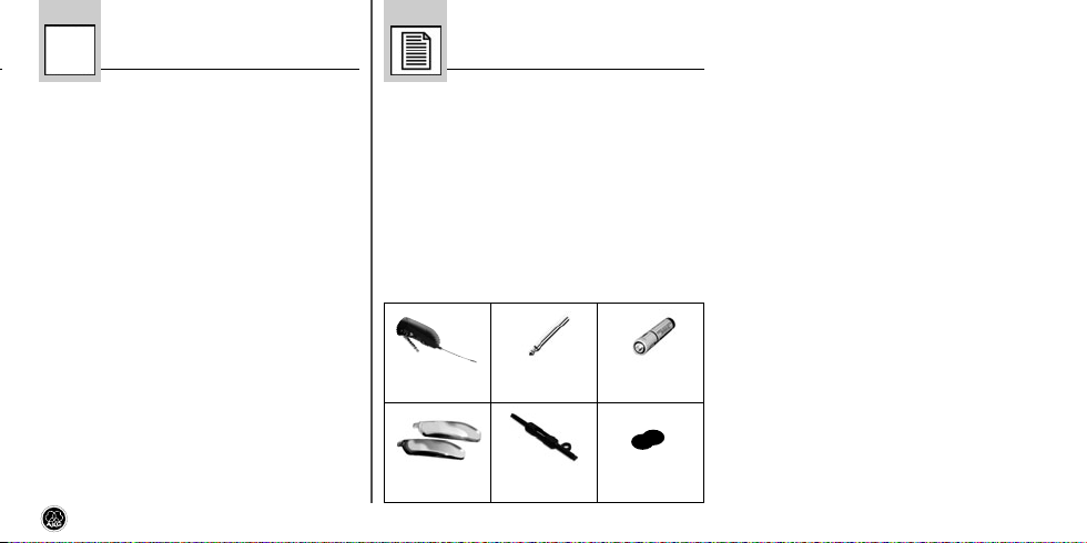
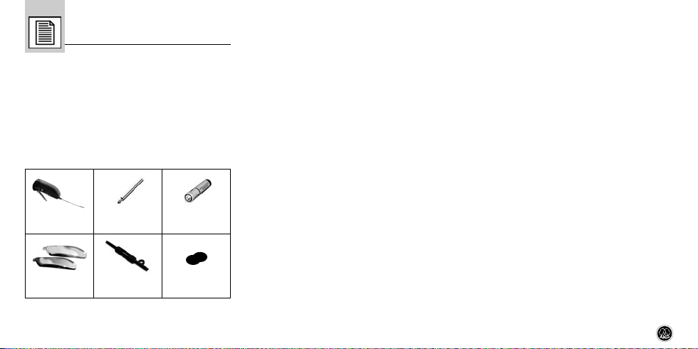
2.2 Lieferumfang
1 Sender
GB 40 FLEXX
2 Batterie -
deckel
1 Adapter -
stecker, lang
1 Schrauben-
zieher
1 Batterie
Größe AAA
1 Klett-
verschluss
• Kontrollieren Sie bitte, ob die Verpackung alle
oben angeführten Teile enthält. Falls etwas fehlt,
wenden Sie sich bitte an Ihren AKG-Händler.
2.3 Optionales Zubehör
• Optionales Zubehör finden Sie im aktuellen
AKG-Katalog/Folder oder auf www.akg.com.
Ihr Händler berät Sie gerne.
2.4 Beschreibung
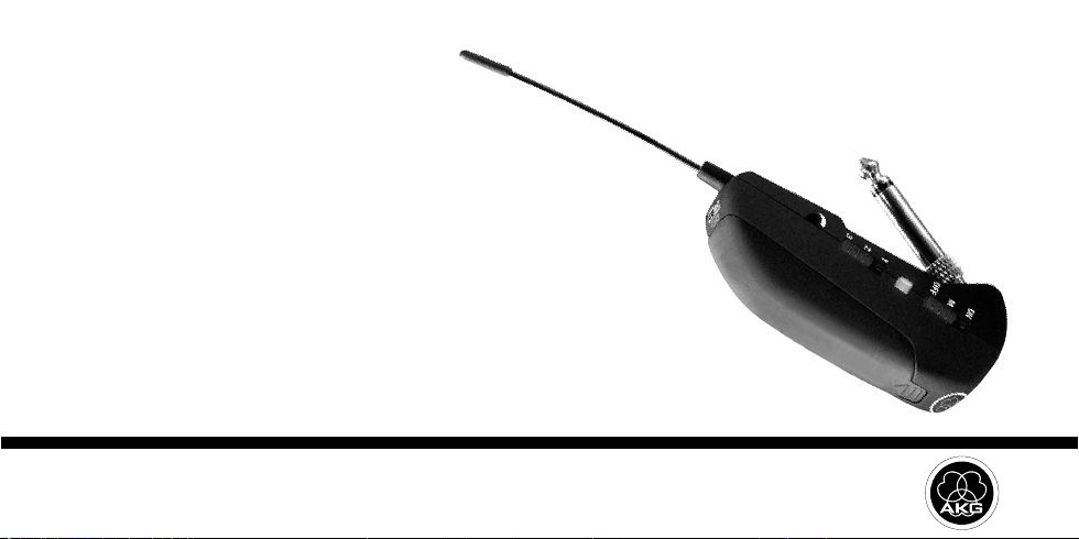
Der GB 40 FLEXX ist ein Miniatursender der Serie
WMS 40 microtools, der speziell für E-Gitarren und
E-Bässe entwickelt wurde, aber auch für
Keyboards geeignet ist.
Der Sender ist mit einem fix verbundenen, schwenkbaren 6,3 mm-Klinken stecker ausgestattet, mit
dem Sie den Sender direkt an die Ausgangsbuchse
Ihres Instruments anstecken können. Eine eingebaute Feder zieht den Sender zum Instrument und
fixiert ihn dadurch sicher am Instrument. Die Unterseite des Senders ist mit einer Auflage aus weichem Kunst stoff ausgestattet, der am Instru ment
keine Spuren hinterlässt.
3
Page 4
Das mitgelieferte Klettband ermöglicht Ihnen, den
Sender zusätzlich zu stabilisieren.
Der GB 40 FLEXX arbeitet auf drei schaltbaren,
quarzstabilisierten Trägerfrequenzen inner halb des
bei der Bestellung gewählten Trägerfrequenzbandes (Bandbreite 3 MHz) im UHF-Träger fre quenzbereich von 660 bis 865 MHz und ist mit einer fix
montierten flexiblen Antenne ausgestattet.
Sie können den Batteriefachdeckel gegen einen der
beiden mitgelieferten Ersatzdeckel austauschen.
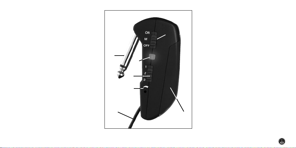
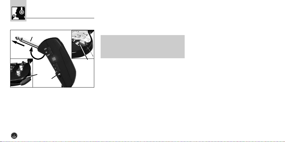
2.5 Bedienelemente (siehe Abb. 1)
1 ON/MUTE/OFF: Dieser Schiebe schalter hat
drei Stellungen:
ON: Die Spannungsversorgung für den Sender
ist eingeschaltet.
M: Das vom Instrument kommende Audio-signal ist stummgeschaltet, Spannungsversor gung und HF-Trägerfrequenz bleiben jedoch
eingeschaltet. Dadurch wird der Empfänger
trotz abgeschaltetem Mikrofon nicht durch
andere Sender gestört.
4
Abb. 1: Bedienelemente GB 40 FLEXX
OFF: Die Spannungsversorgung für den Sender ist ausgeschaltet.
2 Batteriefach für 1 Stk. 1,5 V-Batterie Größe
AAA (mitgeliefert).
3 Kontroll-LED: Diese LED zeigt die Betriebs-
bereitschaft des Senders an.
LED leuchtet grün: Batterie in Ordnung.
LED leuchtet rot: Ab dem Zeitpunkt, wo die
LED auf rot wechselt, reicht die Batteriekapazität noch für maximal 1 Betriebsstunde. Wir
empfehlen, die Batterie sobald wie möglich
gegen eine neue auszutauschen.
4 Eingangspegelregler: Stellt die Empfindlich-
keit des Audioeingangs ein.
5 Klinkenstecker: 6,3 mm-Mono-Klinkenstecker
zum direkten Anschluss des Senders an einen
Klinkenausgang.
6 Flexible Antenne
7 Frequenzwahlschalter: Mit diesem Schiebe-
schalter können Sie den Sender auf eine von
drei verschie denen Trägerfre quenzen innerhalb
des Trägerfrequenzbandes des Senders einstellen.
GB 40 FLEXX guitarbug
Page 5
8 Trägerfrequenzetikette: An der Rückseite des
Senders ist eine Haftetikette mit der Bezeichnung des Träger frequenzbandes, dem entsprechenden Farbcode und den drei Träger frequenzen angebracht. Eine Farbcode-Tabelle
finden Sie im Beiblatt ("Manual Supplement")
zur Bedienungsanleitung.
GB 40 FLEXX guitarbug
3 Inbetriebnahme
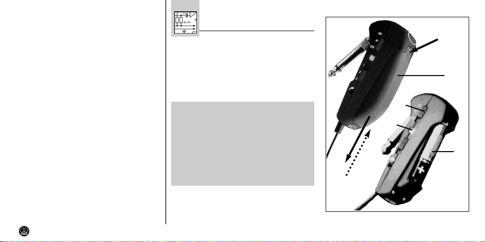
3.1 Batterie einlegen/austauschen und testen
(siehe Abb. 2)
1. Drücken Sie den Schnapphaken am Batteriefach deckel (1) nach unten.
2. Ziehen Sie den Batteriefachdeckel (1) nach unten vom Sender ab.
Wichtig!
!
Der Schaumstoffpolster an der Innen-
L
seite des Batterie fachdeckels (1)
fixiert die Batterie in ihrer Position.
Entfernen Sie den Schaum stoffpolster nicht, da die Batterie ansonsten nicht richtig im Batterie fach
fixiert ist und Klapper geräusche verursachen kann.
3. Wenn sich eine leere oder defekte Batterie im
Batteriefach befindet, nehmen Sie diese heraus.
Abb. 2: Batterie einlegen
5
Page 6

4. Legen Sie die mitgelieferte bzw. neue Batterie
(2) wie in Abb. 2 gezeigt in das Bateriefach ein.
5. Stellen Sie den ON/MUTE/OFF-Schalter (3) auf
ON.
Wenn die Batterie in gutem Zustand ist, blitzt
die Kontroll-LED (4) kurz rot auf und beginnt
danach grün zu leuchten.
Wenn die Kontroll-LED (4) rot zu leuchten
beginnt, ist die Batterie in ca. 60 Minuten erschöpft. Tauschen Sie die Batterie möglichst
bald gegen eine frische aus.
Wenn die Kontroll-LED (4) nicht aufblitzt, ist die
Batterie erschöpft. Legen Sie eine neue Batterie ein.
6. Schieben Sie den Batteriefachdeckel (1) gegen
die Pfeilrichtung auf den Sender, bis der Batteriefach deckel (1) einrastet.
3.2 Betrieb mit Akku
Sie können den Sender anstelle einer normalen
Batterie auch mit einem 1,2 V-Akku betreiben. Wir
empfehlen NiMH-Akkus des Typs SANYO HR-4U
(650 mAh) oder Panasonic Rechargeable PRO+
(550 mAh).
Hinweis: Wenn Sie einen Akku verwenden,
wechselt die LED 15 - 20 Minuten, bevor der
Akku erschöpft ist, auf rot!
6
GB 40 FLEXX guitarbug
Page 7
4 Anwendung
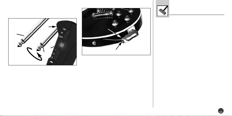
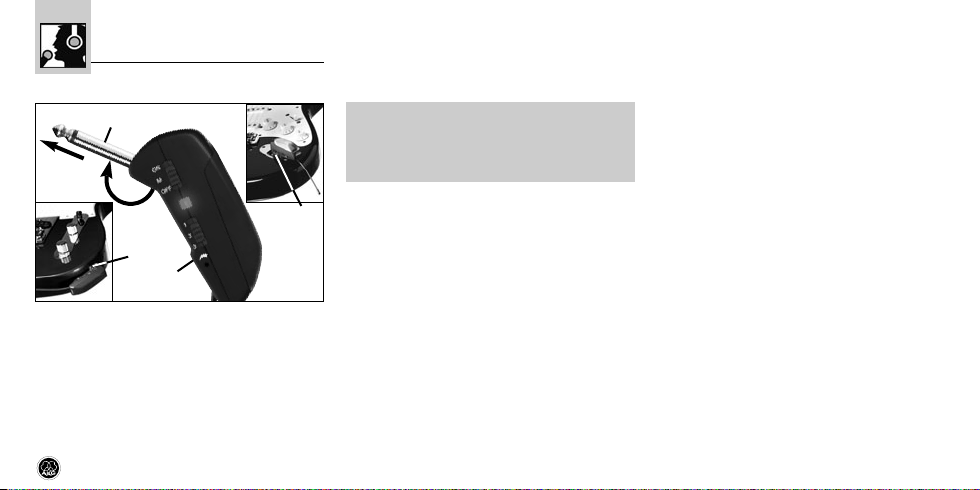
4.1 Sender befestigen (siehe Abb. 3)
Abb. 1: Sender am Instrument befestigen
1. Schwenken Sie den Klinken stecker (1) bis zum
Anschlag vom Sender (2) weg.
2. Stecken Sie den Klinkenstecker (1) bis zum
Anschlag in die Klinken-Ausgangsbuchse (3)
Ihres Instru ments hinein.
Die im Sender eingebaute Feder fixiert den
GB 40 FLEXX guitarbug
Sender sicher am Instrument. Die Auflage aus
weichen Kunststoff an der Unterseite des
Senders hinterlässt keine Spuren an der
Oberfläche des Instruments.
Wichtig!
!
L
Um Beschädigungen des Senders zu
vermeiden, legen oder stellen Sie das
Instrument niemals auf den Sender.
4.2 Pegel einstellen (siehe Abb. 1 und Bedie-
nungsanleitung des Empfängers SR 40 FLEXX)
1. Stellen Sie den Frequenzwahlschalter (7) am
Sender und den Frequenzwahlschalter am
Empfän ger SR 40 FLEXX auf dieselbe Position
(1 - 1, 2 - 2 oder 3 - 3).
2. Drehen Sie den Eingangspegelregler (4) am
Sender mit dem mitgelieferten Schraubenzieher bis zur Mitte zwischen linkem und rechtem
Anschlag auf.
3. Schalten Sie den Sender ein, indem Sie den
ON/MUTE/OFF-Schalter (1) auf ON stellen.
4. Stellen Sie den SQUELCH-Regler am
Empfänger auf Minimum und schalten Sie
den Empfänger und die Audioanlage ein.
5. Drehen Sie den Volume-Regler Ihres Instruments voll auf und spielen Sie einige Takte.
6. Sollte Ihr Instrument verzerrt klingen, drehen
Sie den Eingangspegelregler (4) am Sender so
weit gegen den Uhrzeiger sinn zurück, bis Sie
keine Verzerrung mehr hören.
Sollte Ihr Instrument zu leise klingen, drehen
Sie den Eingangspegelregler (4) im Uhrzeigersinn auf. Sobald Ihr Instrument zu verzerren
beginnen, drehen Sie den Eingangspegelregler
(4) wieder zurück, bis die Verzerrung verschwindet.
4.3 Instrumente mit versenkter Ausgangs-
buchse (siehe Abb. 4 auf Seite 8)
Wenn Ihr Instrument eine versenkte Ausgangsbuchse besitzt, ist der Klinkenstecker am Sender
möglicherweise zu kurz, um den elektrischen Kontakt zum Sender herzustellen.
7
Page 8
Montieren Sie in diesem Fall den mitgelieferten
längeren Adapterstecker:
5 Reinigung
• Reinigen Sie das Gehäuse des Senders mit
einem mit Wasser befeuchteten Tuch.
Abb. 4: Adapterstecker anbringen.
1. Schrauben Sie den Klinkenstecker (1) vom
Sender (2) ab.
2. Schrauben Sie den Adapterstecker (3) auf den
Gewindestecker (4) am Sender (2) auf.
4.4 Sender stabilisieren (s. Abb. 5)
• Verwenden Sie zum Sabilisieren des Senders
den mitgelieferten Klettverschluss:
8
Abb. 5: Sender stabilisieren
1. Ziehen Sie die Schutzfolie von der Rückseite
des einen Teils ab und kleben Sie ihn auf die
Rückseite des Senders.
2. Ziehen Sie die Schutzfolie von der Rückseite
des zweiten Teils ab und kleben Sie ihn auf das
Instrument.
4.5 Fehlerbehebung
Hinweise zur Fehlerbehebung finden Sie in der
Bedienungsanleitung des Empfängers SR 40 FLEXX.
GB 40 FLEXX guitarbug
Page 9

6 Technische Daten
Trägerfrequenz 660 - 865 MHz
Modulation FM
Frequenzstabilität (-10°C bis +50°C): ±15 kHz
HF-Ausgangsleistung typ. 5 mW
Kompander integriert
Audioübertragungsbandbreite 40 - 20.000 Hz
Audio-Eingangsimpedanz 1 MOhm
Max. Audio-Eingangspegel 1100 mV/1 kHz
Klirrfaktor bei 1 kHz typ. 0,8%
Signal/Rauschabstand typ. 103 dB(A)
Spannungsversorgung 1 x 1,5 V-Batterie Größe AAA
Stromaufnahme typ. 75 mA
Betriebszeit >11 h (Batterie), >6 h (Akku)
Abmessungen (BxTxH) 76 x 20 x 28 mm
Nettogewicht (ohne Batterie) 28 g
GB 40 FLEXX guitarbug
Dieses Produkt entspricht den in der Konformitätserklärung angegebenen
Normen. Sie können die Konformitätserklärung auf http://www.akg.com oder
per E-Mail an sales@akg.com anfordern.
9
Page 10

Table of Contents
Page
FCC Statement .....................................................................................11
1 Safety and Environment....................................................................11
1.1 Safety .....................................................................................11
1.2 Environment ............................................................................11
2 Description........................................................................................12
2.1 Introduction .............................................................................12
2.2 Packing List.............................................................................12
2.3
Optional Accessories................................................................12
2.4 Descriptiuon ............................................................................12
2.5 Controls ..................................................................................12
3 Setting Up .........................................................................................13
3.1 Inserting/Replacing and Testing Batteries..................................13
3.2 Using Rechargeable Batteries ...................................................14
10
Page
4 Operating Notes ................................................................................15
4.1 Attaching the Transmitter .........................................................15
4.2 Setting Gain ............................................................................15
4.3 Instruments with Recessed Output Jacks ..................................15
4.4 Stabilizing the Transmitter ........................................................16
4.5 Troubleshooting .......................................................................16
5 Cleaning ............................................................................................16
6 Specifications....................................................................................17
GB 40 FLEXX guitarbug
Page 11
FCC Statement
This equipment has been tested and found to
comply with the limits for a Class B digital device,
pursuant to Part 74 of the FCC Rules. These limits are designed to provide reasonable protection
against harmful interference in a residential installation. This equipment generates, uses, and can
radiate radio frequency energy and, if not installed
and used in accordance with the instructions, may
cause harmful interference to radio communications. However, there is no guarantee that interference will not occur in a particular installation. If
this equipment does cause harmful interference to
radio or television reception, which can be determined by turning the equipment off and on, the
user is encouraged to try to correct the interference by one or more of the follow ing measures:
• Reorient or relocate the receiving antenna.
• Increase the separation between the equipment and the receiver.
• Connect the equipment into an outlet on a circuit different from that to which the receiver is
connected.
• Consult the dealer or an experienced radio/TV
technician for help.
Shielded cables and I/O cords must be used for
this equipment to comply with the relevant FCC
regulations.
Changes or modifications not expressly approved
in writing by AKG Acoustics may void the user’s
authority to operate this equipment.
!
L
1 Safety and Environment
1.1 Safety
1. Do not expose the equipment to direct sunlight, excessive dust, mois ture, rain, mechanical vibrations, or shock.
1.2 Environment
1. Be sure to dispose of used batteries as
required by local waste disposal rules. Never
throw batteries into a fire (risk of explosion) or
garbage bin.
2. When scrapping the equipment, remove the
batteries, separate the case, circuit boards,
and cables, and dispose of all components in
accord ance with local waste disposal rules.
3. The packaging of the equipment is recyclabe.
To dispose of the packaging, make sure to use
a collection/recycling system provided for that
purpose and observe local legislation relating
to waste disposal and recycling.
GB 40 FLEXX guitarbug
11
Page 12
2 Description
2.1 Introduction
Thank you for purchasing an AKG product. Please
take a few minutes to read the instructions
below carefully before operating the equipment. Please keep the Manual for future refer-
ence. Have fun and impress your audience!
2.2 Packing List
1 GB 40 FLEXX
transmitter
2 battery com-
partment lids 1 screwdriver
1 long adapter
plug
• Check that the package contains all the parts
12
1 AAA size
dry batery
1 pairf of
Velcro pads
listed above. If anything is missing, please contact your AKG dealer.
2.3 Optional Accessories
• For optional accessories, refer to the current
AKG catalog or folder, or visit www.akg.com.
Your dealer will be glad to help.
2.4 Description
The GB 40 FLEXX is a WMS 40 microtools Series
miniature transmitter that has been specifically
designed for electric guitars and basses but is also
suited for keyboards.
The transmitter features a permanently attached,
swiveling 1/4" jack plug that allows you to plug the
transmitter directly into the output jack of your
instrument. A built-in spring presses the transmitter against the instrument to hold it securely in
place. The bottom of the transmitter is fitted with a
soft plastic pad that will leave no trace on the
instrument.
The supplied Velcro pads allow you to attach the
transmitter even more firmly to the instrument.
Operating in the 660 MHz to 865 MHz UHF range, the
GB 40 FLEXX provides three selectable, quartz stabilized carrier frequencies within the 3-MHz-wide frequency band you specified at the time of ordering
and
uses a permanently attached flexible antenna.
You can replace the black battery cover with one
of the supplied replacement covers.
2.5 Controls (refer to fig. 1 on page 13)
1 ON/MUTE/OFF: This slide switch provides
three positions:
ON: Power to the transmitter is on.
M: The signal delivered by the microphone is
muted while power and the RF carrier frequency remain on. This prevents the receiver respond ing to interference from other transmitters.
OFF: Power to the transmitter is off.
2 Battery compartment for one 1.5-V AAA size
battery (supplied).
GB 40 FLEXX guitarbug
Page 13
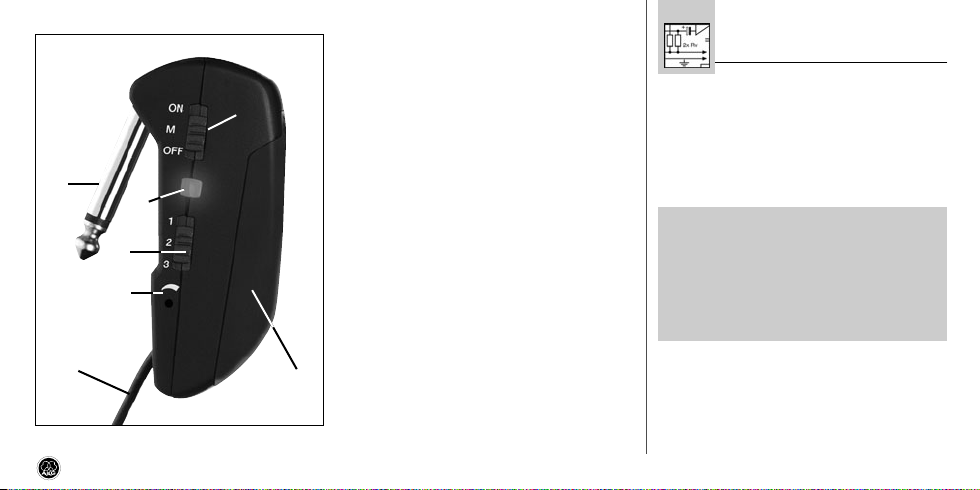
Fig. 1: GB 40 FLEXX controls
GB 40 FLEXX guitarbug
3 Status LED: Indicates the transmitter's operat-
ing status.
LED lit green: Battery is OK.
LED lit red: From the moment the LED changes
to red, the battery capacity will provide a maximum of one operating hour. We recommend
replacing the battery with a new one as soon
as possible.
4 Input Gain: This rotary pot sets the sensitivity
of the transmitter’s audio section.
5 Jack plug: 1/4" TS jack plug for plugging the
transmitter directly into an instrument output
jack.
6 Flexible antenna
7 This slide switch tunes the transmitter to one of
three different carrier frequencies within the
transmitter's carrier frequency band.
8 Carrier frequency label: The label on the trans-
mitter rear panel indicates the name of the carrier frequency band and the three carrier frequencies of your transmitter. Refer to the Manual
Supplement sheet for a color code table.
3.1 Inserting/Replacing and Testing Batteries
(refer to fig. 2 on page 14)
1. Depress the snap hook on the battery com-
2. Pull the battery compartment lid (1) down to
3. If there is a dead or defective battery inside the
4. Insert the supplied or new battery (2) into the
5. Set the ON/MUTE/OFF switch (3) to ON.
3 Setting Up
partment lid (1).
remove it from the transmitter.
Important!
!
L
The foam pad on the inside of the battery compartment lid (1) holds the
battery in place. Do not remove the
foam pad. If you do, the battery will
not be held in place properly and may
cause a rattling noise.
battery compartment, remove the battery.
battery compartment as shown in fig. 2.
13
Page 14
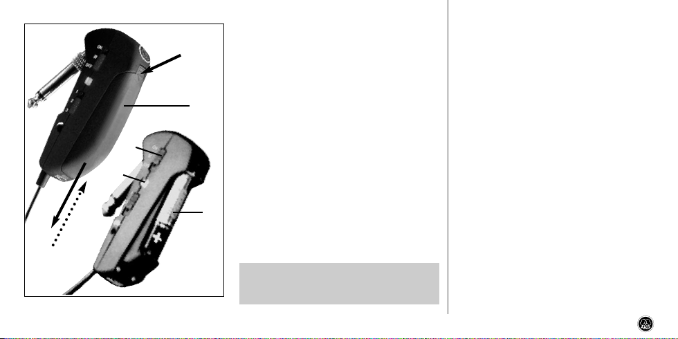
Fig. 2: Inserting a battery.
14
As long as the battery is in good con dition, the
status LED (4) will flash red momentar ily and
will then be lit green constantly.
If the status LED (4) lights red constantly the
battery will be dead within about 60 minutes.
Replace the battery with a new one as soon as
possible.
If the status LED (4) fails to flash momentarily
the battery is dead. Insert a new battery.
6. Slide the battery compartment lid (1) onto the
transmitter against the direction of the arrow to
the point that the lid (1) will click shut.
3.2 Using Rechargeable Batteries)
Instead of dry batteries, you can also use a 1.2-V
rechargeable battery to power the transmitter. We
recommend SANYO HR-4U (650 mAh) or Panasonic Rechargeable PRO+ (550 mAh) NiMH rechargeable batteries.
Note: If you use a rechargeable battery, the LED
will switch to red 15 to 20 minutes before the
battery will be dead!
GB 40 FLEXX guitarbug
Page 15
4 Operating Notes
4.1 Attaching the Transmitter (refer to fig. 3)
Fig. 3: Fixing the transmitter on the instrument.
1. Swivel the jack plug (1) away from the transmitter (2) to the stop.
2. Insert the jack plug (1) all the way into the output jack (3) on your instrument.
The spring inside the transmitter will hold the
transmitter securely in place on the instrument.
GB 40 FLEXX guitarbug
The soft plastic pad on the bottom of the transmitter will leave no trace on the instrument surface.
Important!
!
To avoid damaging the transmitter,
L
NEVER place the instrument on top of
the transmitter.
4.2 Setting Levels (refer to fig. 1
and SR 40 FLEXX receiver manual)
1. Set the frequency selector (7) on the transmitter and the frequency selector on the SR 40 FLEXX
receiver to the same positions (1 - 1, 2 - 2, or
3 - 3).
2. Use the supplied screwdriver to turn the input
gain control (4) on the transmitter to a position
halfway between the left and right stops.
3. Set the ON/MUTE/OFF switch (1) to ON to
switch power to the transmitter on.
4. Set the SQUELCH control on the receiver to
minimum and switch power to your receiver
and sound system on.
5. Turn the volume control on your instrument all
the way CW and play a few bars.
6. If your instrument sounds distorted turn the
input gain control (4) down CCW to the point
that you will hear no more distortion.
If your instrument sounds too quiet, turn the
input gain control (4) up CW. As soon as your
instrument sound becomes distorted, turn the
input gain control (4) back down CCW to the
point that the distortion will stop.
4.3 Instruments with Recessed Output Jacks
(refer to fig. 4 on page 16)
If your instrument has a recessed output jack, the
jack plug on the transmitter may be too short to
make contact be tween the instrument and transmitter.
In this case, mount the supplied long adapter plug:
1. Unscrew the jack plug (1) from the transmitter
(2) CCW.
15
Page 16
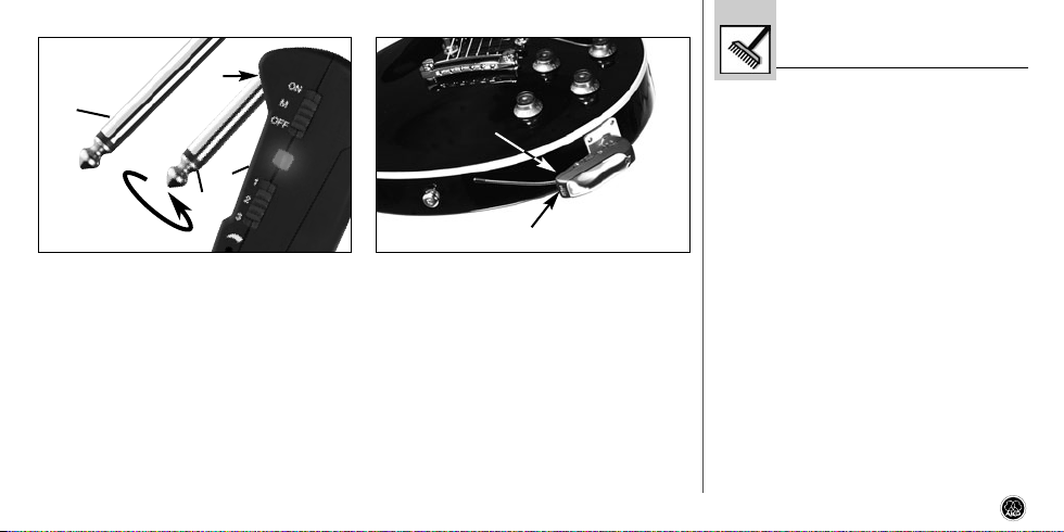
Fig. 4: Mounting the adapter plug. Fig. 5: Stabilizing the transmitter.
5 Cleaning
• To clean the transmitter case, use a soft cloth
moistened with water.
2. Screw the adapter plug (3) onto the threaded
plug (4) on the transmitter (2) CW.
4.4 Stabilizing the Transmitter (refer to fig. 5)
• Use the supplied Velcro pads to make the
transmitter sit more securely on your instrument:
1. Remove the backing from one of the pads and
attach it to the transmitter rear panel.
16
2. Remove the backing from the other pad and
attach it to the instrument.
4.5 Troubleshooting
• For troubleshooting hints, refer to the instruction manual of your SR 40 FLEXX receiver.
GB 40 FLEXX guitarbug
Page 17

6 Specifications
Carrier frequency range 660 to 865 MHz
Modulation FM
Frequency stability (-10°C to +50°C) ±15 kHz
RF output typ. 5 mW
Compander integrated
Audio bandwidth 40 to 20,000 Hz
Audio input impedance 1 Mohm
Max. audio input level 1100 mV/1 kHz
T.H.D. at 1 kHz typ. 0.8%
Signal/noise ratio typ. 103 dB(A)
Power requirement single 1.5-V AAA size battery
Current consumption typ. 75 mA
Battery life >11/>6 hours (dry/rechargeable battery)
Size (WxDxH) 76 x 20 x 28 mm (3 x 0.8 x 1.1 in.)
Net weight 28 g (1 oz.)
GB 40 FLEXX guitarbug
This product conforms to the standards listed in the Declaration of
Conformity. To order a free copy of the Declaration of Conformity, visit
http://www.akg.com or contact sales@akg.com.
17
Page 18

Sommaire
Page
1 Sécurité et écologie ..........................................................................19
1.1 Sécurité ..................................................................................19
1.2 Ecologie ..................................................................................19
2 Description........................................................................................19
2.1 Introduction .............................................................................19
2.2 Equipement fourni....................................................................19
2.3
Accessoires optionnels.............................................................19
2.4 Description ..............................................................................19
2.5 Eléments de commande...........................................................20
3 Mise en service.................................................................................21
3.1 Mise en place/remplacement et essai de la pile ........................21
3.2 Fonctionnement sur accu .........................................................22
4 Mode opératoire................................................................................23
4.1 Fixation de l’émetteur ..............................................................23
18
Page
4.2 Réglage de niveau ...................................................................23
4.3 Instruments avec prise sortie noyée ..........................................23
4.4 Stabilisation de l’émetteur ........................................................24
4.5 Dépannage..............................................................................24
5 Nettoyage..........................................................................................24
6 Caractéristiques techniques .............................................................25
GB 40 FLEXX guitarbug
Page 19

!
L
1 Sécurité et écologie
1.1. Sécurité
1. Ne placez jamais l’appareil à un endroit où il
risque d’être exposé directement au soleil, à
une atmosphère poussiéreuse, à l’humidité, à
la pluie, aux vibrations ou aux secousses.
1.2. Ecologie
1. Conformez-vous aux règlements en vigueur
pour la mise au rebut des piles usées. Ne mettez jamais des piles ni au feu (risque d’explosion) ni aux ordures ménagères.
2. Si vous mettez l'appareil à la ferraille, enlevez
les piles ou les accus, séparez le boîtier, l'électronique et les câbles et éliminez les différents
éléments conformément aux règlements en
vigueur.
3. L'emballage est recyclable. Déposez l'emballage dans un récipient de collecte prévu à cet
effet.
GB 40 FLEXX guitarbug
2 Description
2.1 Introduction
Nous vous remercions d’avoir choisi un produit
AKG. Veuillez lire très attentivement ce mode
d’emploi avant la mise en service de l’appareil.
Conservez soigneusement le mode d’emploi pour
pouvoir le consulter lorsque vous vous posez des
questions. Nous vous souhaitons beaucoup de
succès.
2.2. Equipement fourni
1 émetteur
GB 40 FLEXX
2 couvercles 1 tournevis
1 adaptateur
long
1 pile dimen-
sion AAA
2 disques auto-
agrippants
• Contrôlez si le carton contient bien tous les éléments énumérés ci-dessus. Si ce n’est pas le
cas, veuillez contacter votre distributeur AKG.
2.3 Accessoires optionnels
• Vous trouverez la liste des accessoires optionnels dans le catalogue/dépliant AKG actuel ou
sur www.akg.com. Votre fournisseur se tient à
votre disposition pour vous conseiller.
2.4 Description
Le GB 40 FLEXX est un émetteur miniature de la
gamme WMS 40 microtools ; spécialement conçu
pour la guitare électrique et la basse électrique, il
peut aussi être utilisé pour le clavier.
L’émetteur comporte une fiche jack de 6,35 mm
orientable, à montage fixe, grâce à laquelle vous
pouvez brancher l’émetteur directement sur la prise
sortie de votre instrument. La sécurité de la fixation
est assurée par un ressort incorporé qui tire l’émetteur vers l’instrument. La face inférieure de l’émetteur est revêtue d’une couche de matière plastique
souple ne laissant aucune trace sur l’instrument.
19
Page 20

Les disques autoagrippants fournis permettent une
fixation plus stable de l’émetteur sur l’instrument.
Dans la plage de fréquences choisie lors de la
commande (plage de 3 MHz), le GB 40 FLEXX dispose de trois fréquences porteuses commutables,
stabilisées par cristal, dans la gamme UHF de 660
à 865 MHz ; il possède une antenne souple montée à demeure.
Vous pouvez remplacer le couvercle noir par un
des couvercles de rechange fournis.
2.5 Eléments de commande (voir Fig. 1)
1 ON/MUTE/OFF : Ce curseur peut occuper trois
positions :
ON : L’émetteur est sous tension.
M : Le signal audio venant du micro est sur
muet mais l’émetteur reste sous tension et sur
la porteuse HF. Ceci permet de couper le micro
sans que le récepteur ne soit perturbé par
d’autres émetteurs.
OFF : L’émetteur n’est pas sous tension.
20
2 Compartiment de la pile pour une pile de
1,5 V, dimension AAA (fournie).
3 LED témoin : Ce témoin indique le statut de
disponibilité de l’émetteur.
Le témoin LED s’allume en vert : la pile est
chargée.
Le témoin LED s’allume en rouge : au moment où le témoin passe au rouge, l’autonomie
de la pile n’est plus que de 1 heure. Il est
recommandé de la remplacer au plus vite par
une pile neuve.
4 Potentiomètre d’entrée : règle la sensibilité
de l’entrée audio.
5 Fiche Jack : Jack mono de 6,3 mm pour le
raccordement direct de l’émetteur sur une sortie Jack.
6 Antenne souple
7 Sélecteur de fréquence : ce curseur permet
de sélectionner pour l'émetteur l’une des trois
fréquences porteuses disponibles dans la
gamme des fréquences porteuses de l'émetteur.
Fig. 1 : Eléments de commande sur le GB 40 FLEXX
GB 40 FLEXX guitarbug
Page 21

8 Étiquette des fréquences porteuses : au dos
de l’émetteur, une étiquette indique la gamme
de fréquences porteuses, le code couleur correspondant et les trois fréquences porteuses.
GB 40 FLEXX guitarbug
3 Mise en service
3.1 Mise en place/remplacement et essai de
la pile (voir Fig. 2)
1. Poussez le fermoir du couvercle du compartiment de la pile (1) vers le bas.
2. Enlevez le couvercle du compartiment de la
pile (1) en le faisant glisser vers le bas.
Important !
!
La plaque de mousse à l’intérieur du
L
couvercle du compartiment de la pile
(1) maintient la pile en position.
N’enlevez pas cette plaque, sinon la
pile ne serait pas maintenue correctement et risquerait de provoquer des
bruits importuns.
3. Enlevez, le cas échéant, la pile épuisée ou
défectueuse se trouvant dans le compartiment.
4. Mettez la pile fournie ou la nouvelle pile (2)
dans le compartiment comme indiqué à la
Fig. 2.
Fig. 2 : Mise en place de la pile
21
Page 22

5. Faites occuper au curseur ON/MUTE/OFF (3) la
position ON.
Si la pile est en bon état, la LED témoin (4)
lance un éclair rouge et s’allume en vert aussitot.
Si la LED (4) s’allume en rouge, la pile n’assure plus que 60 minutes d’autonomie. Remplacez-la dès que possible par une pile fraîche.
Si la LED (4) ne s’allume pas, la pile est épuisée et doit être changée.
6. Remettez le couvercle du compartiment de la
pile (1) sur l’émetteur en le faisant glisser dans
le sens inverse de la flèche jusqu’à enclenchement.
3.2 Fonctionnement sur accu
Au lieu d’une pile normale, vous pouvez également
utiliser un accu de 1,2 V. Nous recommandons les
accus NiMH, type SANYO HR-4U (650 mAh) ou
Panasonic Rechargeable PRO+ (550 mAh).
Remarque : Si vous utilisez un accu rechargea-
ble, le témoin passe au rouge 15 - 20 minutes avant que l’accu ne soit complètement
épuisé !
22
GB 40 FLEXX guitarbug
Page 23

4 Mode opératoire
4.1 Fixation de l’émetteur
(voir Fig. 3)
Fig. 3 : Fixation de l’émetteur sur l’instrument
1. Faites pivoter la fiche Jack (1) en l’éloignant de
l’émetteur (2) jusqu’en position de butée.
2. Enfoncez la fiche Jack (1) à fond dans la prise
sortie (3) de votre instrument.
Le ressort intégré dans l’émetteur fixe celui-ci
GB 40 FLEXX guitarbug
en toute sécurité sur l’instrument. La couche
de matière plastique souple revêtant la face
inférieure de l’émetteur ne laisse aucune trace
sur l’instrument.
Important !
!
Pour ne pas endommager l'émetteur,
L
n’appuyez JAMAIS l'instrument sur
l'émetteur.
4.2 Réglage de niveau (voir Fig. 1 et la notice du
récepteur SR 40 FLEXX)
1. Placez le sélecteur de fréquence de l’émetteur
(7) et le sélecteur de fréquence du récepteur
SR 40 FLEXX sur la même position (1 - 1,
2 - 2 ou 3 - 3).
2. A l’aide du tournevis fourni, réglez le potentiomètre d’entrée (4) de l’émetteur sur la position
médiane, à égale distance des butées droite et
gauche.
3. Mettez l’émetteur sous tension en amenant le
curseur ON/MUTE/OFF (1) sur ON.
4. Réglez la commande de SQUELCH du ré-
cepteur sur la position minimale et mettez le
récepteur et l’équipement audio sous tension.
5. Tournez à fond le bouton de réglage de volume
de votre instrument et jouez quelques mesures.
6. Si le son présente des distorsions, faites tourner le potentiomètre d’entrée (4) de l’émetteur
dans le sens inverse des aiguilles de la montre
jusqu’à disparition des distorsions.
Si le son n’arrive pas sous un volume suffisant
aux haut-parleurs, faites tourner le potentiomètre d’entrée (4) dans le sens des aiguilles de
la montre. Dès qu’apparaissent des distorsions
faites tourner le potentiomètre d’entrée (4)
dans le sens inverse jusqu’à disparition des
distorsions.
4.3 Instruments avec prise sortie noyée
(voir Fig. 4 de la page 24)
Si votre instrument a une prise sortie noyée, il se
peut que la fiche Jack de l’émetteur soit trop courte pour établir le contact avec l’émetteur.
23
Page 24

Dans ce cas, montez l’adaptateur pour prise sortie
fourni :
5 Nettoyage
• Nettoyez le boîtier de l'émetteur avec un chif-
fon légèrement humide (eau claire).
Fig. 4 : Montage de l’adaptateur
1. Dévissez la fiche Jack (1) de l’émetteur (2).
2. Vissez l’adaptateur (3) sur la fiche filetée (4) de
l’émetteur (2).
4.4 Stabilisation de l’émetteur (voir Fig. 5)
• Pour stabiliser l’émetteur, utilisez les disques
autoagrippants fournis:
24
Fig. 5: Stabilisation de l’émetteur
1. Collez l’un des disques au dos de l’émetteur
après avoir enlevée le film de protection.
2. Collez le deuxième disque, après avoir enlevée
le film de protection, sur l’instrument.
4.5 Dépannage
• Vous trouverez les instructions relatives au
dépannage dans le mode d’emploi de votre
récepteur.
GB 40 FLEXX guitarbug
Page 25

6 Caractéristiques techniques
Fréquence porteuse 660 - 865 MHz
Modulation FM
Stabilité de fréquence (entre -10°C et +50°C) : ±15 kHz
Puissance sortie HF typ. 5 mW
Compresseur-expanseur intégré
Bande passante audio 40 - 20.000 Hz
Impédance d’entrée audio 1 Mohm
Niveau d’entrée audio maxi. 1100 mV/1 kHz
Distorsion typ. (par harmonique)
pour 1 kHz 0,8 %
Rapport signal sur bruit typ. 103 dB (A)
Alimentation 1 pile de 1,5 V, dimension AAA
Consommation typ. 75 mA
Autonomie > 11 h (pile), > 6 h (accu)
Dimensions (l x p x h) 76 x 20 x 28 mm
Poids net 28 g
GB 40 FLEXX guitarbug
Ce produit est conforme aux normes citées dans la Déclaration de
Conformité, dont vous pouvez prendre connaissance en consultant le site
http://www.akg.com ou en adressant un e-mail à sales@akg.com.
25
Page 26

Indice
Pagina
1 Sicurezza ed ambiente......................................................................27
1.1 Sicurezza ................................................................................27
1.2 Ambiente ................................................................................27
2 Descrizione........................................................................................27
2.1 Introduzione.............................................................................27
2.2 In dotazione.............................................................................27
2.3
Accessori opzionali ..................................................................27
2.4 Descrizione..............................................................................27
2.5 Elementi di comando ...............................................................28
3 Messa in funzione.............................................................................29
3.1 Inserire/sostituire e testare la batteria .......................................29
3.2 Esercizio con accumulatori .......................................................30
4 Impiego .............................................................................................31
4.1 Come fissare il trasmettitore.....................................................31
26
Pagina
4.2 Come regolare il livello .............................................................31
4.3 Strumenti con presa d’uscita a scomparsa................................31
4.4 Come stabilizzare il trasmettitore ..............................................32
4.5 Difetti e rimedi.........................................................................32
5 Pulizia ..............................................................................................32
6 Dati tecnici........................................................................................33
GB 40 FLEXX guitarbug
Page 27

!
L
1 Sicurezza ed ambiente
1.1 Sicurezza
1. Non esponete l’apparecchio direttamente al
sole, alla polvere e all'umidità, alla pioggia, a
vibrazioni o a colpi.
1.2 Ambiente
1. Smaltite le batterie usate e gli accumulatori
usati sempre conformemente alle norme di
smaltimento rispettivamente vigenti. Non gettate le batterie o gli accumulatori nel fuoco
(pericolo di esplosione) o nei rifiuti residui.
2. Se rottamate l’apparecchio, togliete le batterie
risp. gli accumulatori, separate scatola, elettronica e cavi e smaltite tutti i componenti conformemente alle norme di smaltimento vigenti per
essi.
3. L'imballaggio è riciclabile. Smaltite l'imballaggio in un apposito sistema di raccolta.
GB 40 FLEXX guitarbug
2 Descrizione
2.1 Introduzione
Vi ringraziamo di aver scelto un prodotto dell‘AKG.
Leggete per favore attentamente le istruzioni
per l’uso prima di usare l’apparecchio e con-
servate le istruzioni per l’uso per poterle consultare in caso di necessità. Vi auguriamo buon divertimento e molto successo!
2.2. In dotazione
1 trasmettitore
GB 40 FLEXX
2
coperchi
batteria
1 adattatore
lungo
1 cacciavite
1 batteria
tipo AAA
2 dischi
velcrati
• Controllate per favore se la confezione contiene tutti i componenti di cui sopra. Se manca
qualcosa rivolgetevi al vostro rivenditore AKG.
2.3 Accessori opzionali
• Accessori opzionali si trovano nel catalogo/folder attuale dell'AKG o al sito www.akg.com. Il
vostro rivenditore è a vostra disposizione per
eventuali consigli.
2.4 Descrizione
Il GB 40 FLEXX è un trasmettitore in miniatura della
serie WMS 40 microtools, sviluppato appositamente per chitarre elettriche e bassi elettrici, ma adatto anche per keyboards.
Il trasmettitore è dotato di un girevole connettore
jack da 6,3 mm montato in modo fisso con il quale
potete collegare il trasmettitore direttamente alla
presa d’uscita del vostro strumento. Una molla
integrata avvicina il trasmettitore allo strumento fissandolo così in modo sicuro sullo strumento. Il lato
inferiore del trasmettitore è provvisto di uno strato
27
Page 28

di morbida materia sintetica per evitare che il trasmettitore lasci tracce sullo strumento. I dischi velcrati in dotazione permettono una fissazione ancora più stabile sullo strumento.
Il GB 40 FLEXX offre tre frequenze portanti regolabili, stabilizzate a quarzo, all’interno della gamma
delle frequenze prescelta al momento dell’ordine
(gamma 3 MHz), nella gamma delle frequenze portanti UHF da 660 MHz a 865 MHz ed è dotato di
un’antenna flessibile montata in modo fisso.
Potete sostituire il coperchio nero dello scomparto
batteria con uno dei coperchi in dotazione.
2.5 Elementi di comando (vedi fig. 1)
1 ON/MUTE/OFF: Questo interruttore a scorri-
mento ha tre posizioni:
ON: L’alimentazione del trasmettitore è inserita.
M: Il segnale audio proveniente dal microfono
è silenziato, la tensione d’alimentazione e la
frequenza portante RF rimangono inseriti. In
questo modo il trasmettitore non viene disturbato da altri trasmettitori anche quando il
28
Fig. 1: Elementi di comando del GB 40 FLEXX
microfono non è acceso.
OFF: L’alimentazione del trasmetti tore è spenta.
2 Scomparto batteria per 1 batteria da 1,5 V
dimensione AAA (in dotazione).
3 LED di controllo: Questo LED indica lo stato
d’esercizio del trasmettitore.
Il LED è acceso di verde: Batteria o.k.
Il LED è acceso di rosso: A partire dal
momento in cui il LED passa sul rosso, la capacità della batteria basta solo per al massimo
un’ora d’esercizio. Raccomandiamo di sostituire la batteria quanto prima con una nuova.
4 Regolatore del livello d’ingresso: regola la
sensibilità dell’ingresso audio.
5 Connettore jack: connettore jack mono da 6,3
mm per collegare il trasmettitore direttamente
ad un’uscita jack.
6 Antenna flessibile
7 Selettore delle frequenze: Con questo inter-
ruttore a scorrimento potete portare il trasmettitore su una delle tre differenti frequenze portanti, disponibili entro la gamma delle frequenze portanti del trasmettitore.
GB 40 FLEXX guitarbug
Page 29

8 Etichetta delle frequenze portanti: Sul retro
del trasmettitore è disposta un’etichetta adesiva recante il nome della gamma delle frequenze portanti, il relativo codice colori e le tre frequenze portanti. La tabella del codice colori si
trova nel foglio illustrativo ("Manual
Supplement") delle istruzioni per l’uso.
GB 40 FLEXX guitarbug
3 Messa in funzione
3.1 Inserire/sostituire e testare la batteria
(vedi fig. 2)
1. Premete verso il basso il gancio ad innesto disposto sul coperchio dello scomparto batteria
(1).
2. Sfilate il coperchio dello scomparto batteria (1)
dal trasmettitore tirando il coperchio verso il
basso.
Importante!
!
Il cuscinetto in espanso fissato sul
L
lato interno del coperchio dello scomparto batteria (1) fissa la batteria
nella sua posizione. Non togliete il
cuscinetto perché altrimenti la batteria non è fissata bene nello scomparto e può causare rumori.
3. Se c’è una batteria esausta o difettosa nello
scomparto batteria, toglietela.
Fig. 2: Come inserire la batteria
29
Page 30

4. Inserite la batteria in dotazione o una nuova (2)
nello scomparto batteria come indicato nella
fig. 2.
5. Portate l’interruttore ON/MUTE/OFF (3) in posizione ON.
Se la batteria è in buono stato, il LED di controllo (4) si accende brevemente di rosso e poi
si accende rimanendo acceso di verde.
Se il LED di controllo (4) si accende rimanendo
acceso di rosso, la batteria si esaurirà nei prossimi 60 minuti circa. Sostituitela al più presto
con una nuova.
Se il LED di controllo (4) non si accende nemmeno brevemente, la batteria è esausta.
Inserite una batteria nuova.
6. Mettete il coperchio dello scomparto batteria
(1) sul trasmettitore, facendolo scorrere contro
la direzione della freccia fin quando il coperchio (1) scatta.
3.2 Esercizio con accumulatori
Potete far funzionare il trasmettitore anche con un
accumulatore da 1,2 V al posto di una batteria. Vi
raccomandiamo di usare accumulatori NiMH del
tipo SANYO HR-4U (650 mAh) oppure del tipo
Panasonic Rechargeable PRO+ (550 mAh).
Avvertenza: Se usate un accumulatore, il LED
passa sul rosso 15 - 20 minuti prima che
l’accumulatore sia esausto.
30
GB 40 FLEXX guitarbug
Page 31

4 Impiego
4.1 Come fissare il trasmettitore (vedi fig. 3)
Fig. 3: Come fissare il trasmettitore
1. Girate il connettore jack (1) fino all’arresto in
modo che non punti sul trasmettitore (2).
2. Inserite il connettore jack (1) fino all’arresto
nella presa jack d’uscita (3) del vostro strumento.
La molla integrata nel trasmettitore fissa il tra-
GB 40 FLEXX guitarbug
smettitore in modo sicuro sullo strumento. Lo
strato in morbida materia sintetica sul lato inferiore del trasmettitore evita che il trasmettitore
lasci tracce sulla superficie dello strumento.
Importante!
!
L
Per evitare eventuali danni al trasmettitore, non appoggiate MAI lo
strumento sul trasmettitore stesso.
4.2 Come regolare il livello (vedi fig. 1 e le
istruzioni per l’uso del ricevitore SR 40 FLEXX)
1. Portate il selettore delle frequenze (1) disposto
sul trasmettitore e il selettore delle frequenze
(2) disposto sul ricevitore SR 40 FLEXX sulla
stessa posizione (1 - 1, 2 - 2 o 3 - 3).
2. Aprite il regolatore del livello d‘ingresso (4) sul
trasmettitore girandolo con il piccolo cacciavite
in dotazione fin quando si trova al centro tra
arresto sinistro e quello destro.
3. Inserite il trasmettitore portando l’interruttore
ON/MUTE/OFF (1) in posizione ON.
4. Portate il regolatore SQUELCH disposto sul
ricevitore sulla posizione minima e inserite il
ricevitore e l’impianto audio.
5. Aprite il regolatore del volume del vostro
strumento completamente e suonate alcune
battute.
6. Se la riproduzione del vostro strumento presenta distorsioni, portate indietro il regolatore
del livello d’ingresso (4) sul trasmettitore girandolo in senso antiorario fin quando non si sentono più distorsioni.
Se la riproduzione del vostro strumento è troppo bassa, aprite il regolatore del livello d’ingresso (4) di più girandolo in senso orario. Se il
vostro strumento comincia a produrre distorsioni, riportate indietro il regolatore del livello
d’ingresso (4) fin quando le distorsioni scompaiono.
4.3 Strumenti con presa d’uscita a scomparsa
(vedi fig. 4 a pagina 32)
Se il vostro strumento ha una presa d’uscita a
scomparsa, il connettore jack sul trasmettitore
potrebbe essere troppo corto per stabilire il contatto elettrico con il trasmettitore.
31
Page 32

Montate in questo caso il connettore adattatore più
lungo in dotazione:
5 Pulizia
• Pulite la scatola del trasmettitore con un panno
inumidito d’acqua.
Fig. 4: Come montare il connettore adattatore
1. Svitate il connettore jack (1) dal trasmettitore (2).
2. Avvitate il connettore adattatore (3) sul connettore filettato (4) del trasmettitore (2).
4.4 Come stabilizzare il trasmettitore
• Per fissare il trasmettotire in mod più stabile,
usate i dischi velcrati in dotazione:
32
Fig. 5: Stabilizzazione del trasmettitore
1. Sfilate il foglio di protezione dal retro di un
disco e incollatelo sul lato posteriore del trasmettitore.
2. Sfilate il foglio di protezione dal retro dell’altro
disco ed incollatelo sulo strumento.
4.5 Difetti e rimedi
• Le indicazioni come rimediare a difetti sono
contenute nelle istruzioni per l’uso del vostro
ricevitore.
GB 40 FLEXX guitarbug
Page 33

6 Dati tecnici
Frequenza portante 660 - 865 MHz
Modulazione FM
Stabilità della frequenza (da -10°C a +50°C): ±15 kHz
Potenza d’uscita RF tip. 5 mW
Compander integrato
Gamma di trasmissione audio 40 - 20.000 Hz
Impedenza d’ingresso audio 1 Mohm
Livello d’ingresso audio massimo 1100 mV/1 kHz
Fattore di distorsione ad 1 kHz tip. 0,8%
Rapporto segnale/rumore tip. 103 dB(A)
Alimentazione 1 batteria da 1,5 V dimensione AAA
Assorbimento tip. 75 mA
Durata d’esercizio >11 h (batteria), >6 h (accumulatore)
Dimensioni (largh. x prof. x alt.) 76 x 20 x 28 mm
Peso netto 28 g
GB 40 FLEXX guitarbug
Questo prodotto corrisponde alle norme elencate nella dichiarazione di conformità, che è disponibile al sito http://www.akg.com oppure all'indirizzo
email sales@akg.com.
33
Page 34

Índice
Página
1 Seguridad y medio ambiente............................................................35
1.1 Seguridad................................................................................35
1.2 Medio ambiente.......................................................................35
2 Descripción .......................................................................................35
2.1 Introducción ............................................................................35
2.2 Volumen de suministros ...........................................................35
2.3
Accesorios opcionales..............................................................35
2.4 Descripción .............................................................................35
2.5 Elementos de mando ...............................................................36
3 Puesta en funcionamiento ................................................................37
3.1 Colocar/cambiar y ensayar la pila .............................................37
3.2 Funcionamiento con acumulador ..............................................38
4 Aplicaciones......................................................................................39
4.1 Sujetar el transmisor................................................................39
34
Página
4.2 Ajustar el nivel.........................................................................39
4.3 Instrumentos con jack de salida empotrado...............................40
4.4 Estabilización del transmisor.....................................................40
4.5 Reparación de desperfectos .....................................................40
5 Limpieza............................................................................................40
6 Datos técnicos...................................................................................41
GB 40 FLEXX guitarbug
Page 35

!
L
1 Seguridad y medio ambiente
1.1 Seguridad
1. No exponer el aparato directamente al sol, a
polvo o humedad intensos, a la lluvia, a vibraciones o a golpes.
1.2 Medio ambiente
1. Las pilas y los acumuladores usados deben eliminarse atendiendo a las correspondientes disposiciones de eliminación de residuos vigentes. Las pilas o acumuladores no deben tirarse
ni al fuego (peligro de explosión) ni a la basura
residual.
2. Para desguazar el aparato hay que sacar las
pilas o los acumuladores, separar la caja, la
electrónica y el cable y proceder a la eliminación de todos los componentes atendiendo a
las correspondientes disposiciones de eliminación de residuos vigentes.
3. El embalaje es reciclable. Elimine el embalaje
en un sistema de recogida previsto para ello.
GB 40 FLEXX guitarbug
2 Descripción
2.1 Introducción
Muchas gracias por haberse decidido por un producto de la empresa AKG. Tómese, por favor, unos
momentos para leer el Modo de Empleo antes de
usar el aparato. Guarde las instrucciones de empleo
en un lugar seguro de modo que pueda consultarlas
si se le presenta alguna duda. ¡Que se divierta y que
tenga mucho éxito con su nuevo equipo!
2.2. Volumen de suministros
1 transmisor
GB 40 FLEXX
2 tapas
de pilas
1 conector
adaptador largo
1 desatorn-
illador 2 discos velcro
tamaño AAA
1 pila
• Sírvase controlar si el embalaje contiene todas
las piezas indicadas arriba. Si falta algo, le
rogamos dirigirse a su distribuidor AKG.
2.3 Accesorios recomendados
• Los accesorios opcionales los encontrará en el
más reciente Catálogo/Folleto de AKG o en
www.akg.com. Su distribuidor lo asesorará con
mucho gusto.
2.4 Descripción
El GB 40 FLEXX es un transmisor miniatura de la
serie WMS 40 microtools, desarrollado especialmente para guitarras y contrabajos eléctricos, pero
que también se puede usar para instrumentos de
teclado.
El transmisor dispone de una clavija jack de
6,3 mm, fija y orientable, que puede conectar directamente al jack de salida de su instrumento. Un
resorte integrado tira el transmisor hacia el instrumento, fijándolo firmemente en el mismo. La parte
inferior del transmisor tiene una capa de material
sintético blando que no deja huellas en el instrumento.
35
Page 36

Los discos velcro suministradas permiten una estabilización adicional del transmisor en el instrumento.
El transmisor de bolsillo GB 40 FLEXX ofrece tres
frecuencias portadoras estabilizadas por cuarzo y
regulables dentro de la banda de frecuencias elegida con el pedido (ancho de banda 3 MHz) en la
gama de frecuencia portadora UHF de 660 MHz a
865 MHz y está equipado con una antena fija flexible. La tapa de la caja de pilas negra la puede
reemplazar por una de las tapas suministradas.
2.5 Elementos de mando (véase Fig. 1)
1 ON/MUTE/OFF: este conmutador corredizo
tiene tres posiciones:
ON: la alimentación de corriente para el transmisor está conectada.
M: la señal audio que proviene del micrófono
está en mudo, pero la alimentación de corriente y la frecuencia portadora de AF siguen
conectadas. Esto hace que el receptor no se
vea perturbado por otros transmisores a pesar
de tener el micrófono desconectado.
36
Fig. 1: Elementos de mando del GB 40 FLEXX
OFF: la alimentación de corriente del transmisor está desconectada.
2 Caja de pilas para 1 pila de 1,5 V tamaño AAA
(suminstrada).
3 LED de control: este LED indica el estado de
servicio del transmisor.
El LED se ilumina de verde: la pila está en
orden.
l LED se ilumina de rojo: a partir del momen-
to en que el LED cambia a rojo, la capacidad de
la pila es todavía de un máximo de 1 hora de
servicio. Recomendamos recambiar la pila
cuanto antes por una nueva.
4 Control de nivel de entrada: ajusta la sensi-
bilidad de la entrada audio.
5 Clavija jack: clavija jack mono de 6,3 mm
para conectar directamente el transmisor a un
jack de salida
6 Antena flexible
7 Conmutador de frecuencias: con este conmu-
tador corredizo puede regular el transmisor en
una de tres frecuencias portadoras diferentes
dentro de la banda de frecuencias del transmisor.
GB 40 FLEXX guitarbug
Page 37

8 Etiqueta de frecuencia portadora: en la
placa posterior del transmisor está pegada una
etiqueta con la designación de la banda de frecuencias portadoras, el correspondiente código de colores y las tres frecuencias portadoras.
En el Suplemento al Manual de Instrucciones
("Manual Supplement") se encuentra una tabla
con el código de colores.
GB 40 FLEXX guitarbug
3 Puesta en funcionamiento
3.1 Colocar/cambiar y ensayar la pila (véase
Fig. 2)
1. Apriete hacia abajo el gancho de presión de la
tapa de la caja de pilas (1).
2. Retire la tapa de la caja de pilas (1) del transmisor, tirando hacia abajo.
¡Importante!
!
El relleno de goma espuma en el inte-
L
rior de la tapa de la caja de pilas (1)
fija la pila en su posición. ¡El relleno
no se debe quitar, puesto que de
hacerlo, la pila no quedará bien fijada
en la caja, lo que puede producir ruidos de tableteo!
3. Si en la caja de pilas hay una pila descargada
o defectuosa, sírvase sacarla.
4. Coloque la pila suministrada o nueva (2) en la
caja de pilas, tal como se indica en la Fig. 2.
Fig. 2: Introducir la pila
37
Page 38

5. Coloque el conmutador ON/MUTE/OFF (3) en
ON.
Si la pila está en buen estado, el LED de control (4) se ilumina de rojo brevemente y después emitirá luz verde.
Cuando el LED de control (4) empieza a emitir
luz roja constantemente, la pila estará agotada
en aprox. 60 minutos. Cambie la pila cuanto
antes por una nueva.
Si el LED de control (4) no relampaguea, la pila
está agotada. Coloque una pila nueva.
6. Empuje la tapa de la caja de pilas (1) sobre el
transmisor en dirección contraria a la flecha,
hasta que quede enclavada.
3.2 Funcionamiento con acumulador
El transmisor se puede hacer funcionar también
con un acumulador de 1,2 V en lugar de una pila
normal. Recomendamos los acumuladores NiMH
del tipo SANYO HR-4U (650 mAh) o Panasonic
Recharge able PRO+ (550 mAh).
Nota: Si se utiliza un acumulador, 15 minutos
antes de que éste esté agotado, el LED pasa
a rojo.
38
GB 40 FLEXX guitarbug
Page 39

4 Aplicaciones
4.1 Sujetar el transmisor (véase Fig. 3)
Fig. 3: Sujetar el transmisor
1. Gire la clavija jack (1) alejándola del transmisor
(2) hasta que llegue al tope.
2. Introduzca la clavija jack (1) hasta el tope en el
jack de salida (3) de su instrumento.
El resorte integrado en el transmisor lo fija en
forma segura en el instrumento. La capa de
GB 40 FLEXX guitarbug
material sintético blando en la parte inferior del
transmisor no deja ninguna huella en la superficie del instrumento.
¡Importante!
!
Para evitar daños al transmisor, no
L
apoye NUNCA el instrumento en el
transmisor.
4.2 Ajustar el nivel (véase Fig. 1 y el Modo de
empleo del receptor SR 40 FLEXX)
1. Coloque el conmutador de frecuencias (1) del
transmisor y el conmutador de frecuencias (2)
del receptor SR 40 FLEXX en la misma posición
(1-1, 2-2 ó 3-3).
2. Gire el control de nivel de entrada (4) del transmisor con el pequeño desatornillador suministrado hasta el centro, entre el tope izquierdo y
derecho.
3. Encienda el transmisor, colocando el conmutador ON/MUTE/OFF (1) en ON.
4. Coloque el regulador SQUELCH del receptor
en mínimo y encienda el receptor y el equipo
audio.
5. Ponga el regulador de volumen de su instrumento al máximo y toque unos compases.
6. Si su instrumento suena distorsionado, gire el
control de nivel de entrada (4) del transmisor
hacia atrás en sentido contrario a las agujas
del reloj hasta que ya no oiga ninguna distorsión.
Si su instrumento suena muy bajo, gire el control de nivel de entrada (4) en sentido de las
agujas del reloj. En cuanto su instrumento
empiece a distorsionar, gire otra vez el control
de nivel de entrada (4) hacia atrás, hasta que
desaparezca la distorsión.
4.3 Instrumentos con jack de salida empotra-
do (véase Fig. 4 en la página 40)
Si su instrumento tiene un jack de salida empotrado, la clavija jack del transmisor será quizás muy
corta para hacer contacto con el transmisor.
En ese caso, monte el conector adaptador más
largo suministrado:
39
Page 40

Fig. 4: Montaje del conector adaptador Fig. 5: Estabilizar el transmisor
5 Limpieza
• Limpie la caja del transmisor con un paño
humedecido en agua.
1. Desatornille la clavija jack (1) del transmisor (2).
2. Atornille el conector adaptador (3) en el conector de rosca (4) del transmisor (2).
4.4 Estabilización del transmisor (véase Fig. 5)
• Utilice los discos velcor suministrados para
sujetar el transmisor de manera más estable
en el instrumento:
1. Saque la protección del dorso de una de los
40
discos velcro y pegue el disco sobre el dorso
del transmisor.
2. Saque la protección del dorso del otra disco
velcro y péguelo al instrumento.
4.5 Reparación de desperfectos
• Las indicaciones para la reparación de desperfectos las encuentra en el Modo de empleo del
receptor SR 40 FLEXX.
GB 40 FLEXX guitarbug
Page 41

6 Datos técnicos
Frecuencia portadora: 660 – 865 MHz
Modulación: FM
Estabilidad de frecuencia (-10°C hasta +50°C): ±15 kHz
Potencia de salida RF típ.: 5 mW
Compansor: integrado
Ancho de banda de transmisión audio: 40 – 20.000 Hz
Impedancia de entrada audio: 1 Mohmio
Nivel de entrada audio máx.: 1100 mV/1 kHz
Factor de distorsión no lineal con 1 kHz típ.: 0,8%
Relación señal a ruido típ.: 103 dB(A)
Alimentación de corriente: 1 pila de 1,5 V tamaño AAA
Toma de corriente típ.: 75 mA
Horas de servicio: >11 h (pila), >6 h (acumulador)
Dimensiones (an x prof x al): 76 x 20 x 28 mm
Peso neto: 28 g
GB 40 FLEXX guitarbug
Este aparato corresponde a las normas citadas en la declaración de conformidad. Esta última está disponible en el sitio http://www.akg.com o puede
ser solicitada al correo electrónico sales@akg.com.
41
Page 42

Índice
Página
1 Segurança e meio ambiente.............................................................43
1.1 Segurança...............................................................................43
1.2 Meio ambiente.........................................................................43
2 Descrição ..........................................................................................43
2.1 Introdução ...............................................................................43
2.2 Coneúdo da embalagem ..........................................................43
2.3
Acessórios opcionais................................................................43
2.4 Descrição ................................................................................43
2.5 Elementos de controle..............................................................44
3 Acionamento .....................................................................................45
3.1 Colocar/trocar a pilha e testá-la................................................45
3.2 Uso com acumulador ...............................................................46
4 Operação...........................................................................................47
4.1 Fixar o emissor ........................................................................47
42
Página
4.2 Ajustar o nível..........................................................................47
4.3 Instrumentos com saída embutida ............................................47
4.4 Estabilizar o emissor ................................................................48
4.5 Resolver problemas .................................................................48
5 Limpeza.............................................................................................48
6 Especificações ..................................................................................49
GB 40 FLEXX guitarbug
Page 43

!
L
1 Segurança e meio ambiente
1.1 Segurança
1. Não exponha o dispositivo à radiação solar,
poeira ou umidade, chuva, vibrações e golpes.
1.2 Meio ambiente
1. Pilhas e acumuladores esgotados deverão ser
eliminados conforme as respectivas normas
estabelecidas por lei. Não jogue as pilhas no
fogo (perigo de explosão) nem no lixo doméstico.
2. Quando pretende desfazer-se do aparelho,
remova as pilhas ou os acumuladores, separe
a carcaça, a eletrônica e os cabos e providencie que estes serão eliminados conforme as
normas estabelecidas por lei.
3. A embalagem é reciclável. Elimine a embalagem num sistema de colheita apropriado.
GB 40 FLEXX guitarbug
2 Descrição
2.1 Introdução
Agradecemos a sua preferência por um produto da
AKG. Por favor reserve alguns minutos para ler
este manual antes de acionar este equipamento e guarde as instruções cuidadosamente para
sempre poder consultá-las em caso de aparecerem
quaisquer perguntas. Divirta-se e bom trabalho!
2.2 Conteúdo da embalagem
1 emissor
GB 40 FLEXX
2 tampas de
pilha
1 adaptador
comprido
1 chave de
parafuso
1 pilha
tamanho AAA
2 discos de
velcro
• Verifique se a embalagem contém todos os
componentes acima indicados. Caso falte algo,
favor entre em contato com a concessionária
da AKG.
2.3 Acessórios opcionais
• Os acessórios opcionais encontrará no catálogo/na brochura atual da AKG ou em
www.akg.com. A concessionária terá mais
informações disponíveis.
2.4 Descrição
O GB 40 FLEXX é um miniemissor da série WMS
40 microtools que foi desenvolvido especialmente
para guitarra elétrica e baixo elétrico, mas que
pode ser usado também para teclados.
O emissor está provido de um plugue jack giratório
de 6,3 mm que lhe permite ligar o emissor diretamente à saída do seu instrumento. Uma mola integrada aproxima o emissor do instrumento, fixandoo de forma segura no instrumento. O lado de baixo
do emissor está provido de uma proteção de plástico mole que não deixa quaisquer vestígios no instrumento.
43
Page 44

Os discos de velcro incluídos na embalagem permitem uma fixação mais estável do emissor no instrumento.
O GB 40 FLEXX funciona na faixa de freqüência portadora UHF de 660 MHz a 865 MHz. Proporciona
três freqüências portadoras comutáveis e estabilizadas a cristal dentro da banda de freqüências escolhida no seu pedido (largura da banda 3 MHz) e
está provido duma antena flexível fixa.
Pode substituir a tampa preta por uma das tampas
de reposição fornecidas na embalagem.
2.5 Elementos de controle (veja fig. 1)
1 ON/MUTE/OFF: esta barra deslizante possui
três posições:
ON: a alimentação de corrente do emissor está
ligada.
M: o sinal de áudio proveniente do microfone
está mudo, a alimentação de corrente e a freqüência portadora RF, porém, permanecem
ligadas. Desta forma o emissor não é perturbado por outros emissores embora o microfone
esteja desligado.
44
Fig. 1: Controles do GB 40 FLEXX
OFF: a alimentação de corrente do emissor
está desligada.
2 Compartimento de pilha para 1 pilha de 1,5 V
tamanho AAA (fornecida na embalagem).
3 LED de controle: este LED indica que o emis-
sor está pronto para operação.
O LED brilha em cor verde: a pilha está em
ordem.
O LED brilha em cor vermelha: a partir do
momento em que o LED muda para a cor vermelha, a capacidade da pilha chega apenas
para 1 hora no máximo. Recomendamos substituir a pilha o mais depressa possível por uma
pilha nova.
4 Ajuste do nível de entrada: ajusta a sensibi-
lidade da entrada de áudio.
5 Plugue jack de 6,3 mm para a conexão dire-
ta a uma saída jack.
6 Antena flexível
7 Selector de freqüência: com esta chave des-
lizante pode ajustar o emissor a uma das três
freqüências portadoras diferentes dentro da
banda de freqüências portadoras do emissor.
GB 40 FLEXX guitarbug
Page 45

8 Etiqueta de freqüência portadora: no lado
de trás do emissor encontra-se uma etiqueta
adesiva, indicando a banda de freqüências portadoras e o respectivo código de cores assim
como as três freqüências portadoras do emissor.
3 Acionamento
3.1 Colocar/trocar a pilha e testá-la (veja fig. 2)
1. Empurre o gancho de engate na tampa do
compartimento de pilha (1) para baixo.
2. Retire a tampa do compartimento de pilha (1)
do emissor vindo do lado de baixo.
GB 40 FLEXX guitarbug
Importante!
!
O cubinho de borracha esponjosa no
L
interior da tampa do compartimento
de pilha (1) fixa a pilha na sua posição. Não retire o cubinho de borracha
esponjosa porque senão a pilha não
está fixada corretamente no compartimento.
3. Se houver uma pilha gasta ou defeituosa no
compartimento de pilha, retire-a.
4. Coloque a pilha nova ou a pilha fornecida na
embalagem (2) no compartimento como é mostrado na fig. 2.
Fig. 2: Colocar a pilha
45
Page 46

5. Posicione o comutador ON/MUTE/OFF (3) em
ON.
Quando a pilha está em ordem, o LED de controle (4) acende-se brevemente em cor vermelha a depois brilhará em cor verde
Quando o LED de controle (4) começa a brilhar
em cor vermelha, a pilha estará esgotada dentro de ca. 60 minutos Troque-a depressa por
uma pilha nova.
Se o LED de controle (4) não se acender, a pilha
está esgotada. Coloque uma pilha nova.
6. Empurre a tampa do compartimento de pilha
(1) no emissor contra o sentido da seta, até a
tampa do compartimento (1) engatar.
3.2 Uso com acumulador
Em vez de usar uma pilha normal, pode operar o
emissor também com um acumulador de 1,2 V.
Recomendamos acumuladores NiMH do tipo
SANYO HR-4U (650 mAh) ou Panasonic Rechargeable PRO+ (550 mAh).
Nota: Se usar um acumulador, o LED mudará
para vermelho 15 minutos antes de o acumulador ficar esgotado!
46
GB 40 FLEXX guitarbug
Page 47

4 Operação
4.1 Fixar o emissor (veja fig. 3)
Fig. 3: Fixar o emissor no instrumento
1. Gire o plugue jack (1) para fora do emissor (2)
até o ponto final.
2. Enfie o plugue jack (1) até atingir o ponto final
na saída jack (3) do seu instrumento.
A mola integrada no emissor fixa de forma
GB 40 FLEXX guitarbug
segura o emissor no instrumento. O lado de
baixo do emissor com a proteção de plástico
mole não deixa quaisquer vestígios no instrumento.
Importante!
!
Para evitar prejuízos ao emissor,
L
NUNCA apóie o instrumento no mesmo
emissor.
4.2 Ajustar o nível (veja fig. 1 e o manual de ins-
truções do receptor SR 40 FLEXX)
1. Coloque a chave de seleção de freqüências (1)
no emissor e a chave de seleção de freqüências (2) no receptor SR 40 FLEXX na mesma
posição (1 - 1, 2 - 2 ou 3 - 3).
2. Gire o ajuste do nível (4) no emissor com a
chave de prarfuso pequena fornecida na
embalagem até o meio entre os pontos finais
direito e esquerdo.
3. Ligue o emissor posicionando o comutador
ON/MUTE/OFF (1) em ON.
4. Ajuste o regulador SQUELCH no receptor ao
valor mínimo e ligue o receptor e a instalação
de áudio.
5. Abra o volume do seu instrumento ao máximo
e toque alguns compassos.
6. Se o som do seu instrumento estiver distorcido, vire o ajuste do nível de entrada (4) no sentido anti-horário até a distorção desaparecer.
Se o som do seu instrumento estiver demasiadamente baixo, gire o ajuste do nível de entrada (4) no sentido horário. Logo que aparecerem distorções no som do seu instrumento,
gire o ajuste do nível de entrada (4) para trás
até as distorções desaparecerem.
4.3 Instrumentos com saída embutida
(veja fig. 4 na página 48)
Se o seu instrumento possuir uma saída embutida
o plugue jack no emissor talvez não consiga estabelecer o contato elétrico.
Neste caso instale o plugue adaptador fornecido na
embalagem:
47
Page 48

Fig. 4: Fixar o plugue adaptador. Fig. 5: Estabilizar o emissor no instrumento.
5 Limpeza
• Limpe a carcaça do emissor com um pano
umedecido com água.
1. Desenrosque o plugue jack (1) do emissor (2).
2. Rosque o plugue adaptador (3) no plugue roscado (4) do emissor (1).
4.4 Estabilizar o emissor (veja fig. 5)
• Utilize os discos de velcro fornecidas na embalagem para fixar o emissor de forma mais estável no emissor:
48
1. Retire a folha de proteção do lado de trás de
um dos discos e cole-o no lado de trás do
emissor.
2. Cole o outro disco de velcro no instrumento.
4.5 Resolver problemas
• Os avisos para resolver problemas encontrará
no manual do usuário do receptor SR 40 FLEXX.
GB 40 FLEXX guitarbug
Page 49

6 Especificações
Freqüência portadora 660 - 865 MHz
Modulação FM
Estabilidade de freqüência (-10°C a +50°C): ±15 kHz
Potência de saída RF tip. 5 mW
Compressor/Expansor integrado
Largura de banda áudio 40 - 20.000 Hz
Impedância de entrada de áudio 1 Mohm
Nível de entrada de áudio máx. 1100 mY/1 kHz
Distorção não-linear em 1 kHz typ. 0,8%
Relação sinal/ruído tip. 103 dB(A)
Alimentação de corrente pilha de 1 x 1,5 V tamanho AAA
Consumo de corrente tip. 75 mA
Funcionamento >11 h (pilha), >6 h (acumulador)
Dimensões (LxPxA) 76 x 20 x 28 mm
Peso neto 28 g
GB 40 FLEXX guitarbug
Este produto corresponde às normas citadas na declaração de conformidade,
que pode pedir na nossa página da web http://www.akg.com, ou enviandonos um email para sales@akg.com.
49
Page 50

Notizen | Notes | Notes | Note | Notas | Notas
50
GB 40 FLEXX guitarbug
Page 51

Notizen | Notes | Notes | Note | Notas | Notas
GB 40 FLEXX guitarbug
51
Page 52

Mikrofone · Kopfhörer · Drahtlosmikrofone · Drahtloskopfhörer · Kopfsprechgarnituren · Akustische Komponenten Microphones | Headphones · Wireless Microphones · Wireless Headphones · Headsets ·
Electroacoustical Components | Microphones · Casques HiFi · Microphones sans fil · Casques sans fil · Micros-casques · Composants acoustiques | Microfoni · Cuffie HiFi · Microfoni senza filo · Cuffie senza
filo · Cuffie-microfono · Componenti acustici | Micrófonos · Auriculares · Micrófonos inalámbricos · Auriculares inalámbricos · Auriculares con micrófono · Componentes acústicos | Microfones · Fones de ouvido · Microfones
s/fios · Fones de ouvido s/fios · Microfones de cabeça · Componentes acústicos
AKG Acoustics GmbH
Lemböckgasse 21–25, 1230 Vienna/AUSTRIA, phone: +43-1 86654-0*
e-mail: sales@akg.com
For other products and distributors worldwide visit www.akg.com
Technische Änderungen vorbehalten. Specifications subject to change without notice. Ces caractéristiques sont susceptibles de modifications. Ci riserviamo il diritto di effettuare modifiche tecniche. Nos reservamos el derecho de introducir modificaciones técnicas. Especificações sujeitas a mudanças sem aviso prévio.
Printed in China (P.R.C.)
10/08/9100 U 12910
 Loading...