

Page 1

DMS700
USER INSTRUCTIONS . . . . . . . .p. 2
Please read the manual before using the equipment!
BEDIENUNGSANLEITUNG . . S. 30
Bitte vor Inbetriebnahme des Gerätes lesen!
MODE D’EMPLOI . . . . . . . . . . . . . . . . p. 58
Veuillez lire cette notice avant d’utiliser le système!
MODO DE EMPLEO . . . . . . . . . . . . p. 8 6
¡Sirvase leer el manual antes de utilizar el equipo!
Firmware V 2.0
Page 2

DMS
700
Thank you
Symbols Used
Important Note!
for purchasing an AKG product. This manual contains important instructions for setting up and operating your equipment. Please take a few minutes to read the instructions below carefully be-
fore operating the equipment. Please keep the manual for future reference. We hope you enjoy
using your system!
The lightning flash with arrowpoint in an equilateral triangle means that there are dangerous voltages present within the unit.
↯
L
The exclamation point in an equilateral triangle on the equipment indicates that it is necessary for the user to refer to the User Manual. In the User Manual, this symbol marks in-
!
L
structions that the user must follow to ensure safe operation of the equipment.
• AKG continually improves the internal firmwareof the DMS700 system in order tomeet
!
L
changing customer needs in the best possible way. Should your system use a different
firmware versionthan the one described inthis usermanual, somefunctions maydiffer
from the related instructions.
• To find out the actual firmware version implemented in your system,please check the
menu. Thefirmware version described in this user manual is stated on thecover page.
• Before you read on, we recommend comparing the receiver firmware version against
the version described in the manual. If the two versions are not identical, please visit
www.akg.com to find out about the latest changes.
FCC Statement
The DHT 700 D5, DHT 700 D7,DHT 700 C5, and DPT 700 have been tested and found to comply with the limits for a low-power auxiliary station pursuant to Part 74 of the FCC Rules.The DSR
700 has been tested and found to comply with the limits for a Class B digital device, pursuant to
Part 15 of the FCC Rules. These limits are designed to provide reasonable protection against
harmful interference in a residential installation.This equipment generates,uses, and can radiate
radio frequency energy and, if not installed and used in accordance with the instructions, may
cause harmful interference to radio communications. However, there is no guarantee that interference willnot occur in a particular installation.If this equipment does cause harmful interference
to radio or television reception,which can bedetermined by turningthe equipment off and on, the
user is encouraged to try to correct the interference by one or more of the following measures:
• Reorient or relocate the receiving antenna.
• Increase the separation between the equipment and the receiver.
• Connect the equipment into an outlet ona circuit differentfrom thatto which the receiver
is connected.
• Consult the dealer or an experienced radio/TV technician for help.
Shielded cables and I/O cords must be used for this equipment to comply with the relevant FCC
regulations.
Changes or modifications not expressly approved in writing by AKGAcoustics may void the user’s
authority to operate this equipment.
The DSR 700 complies with Part 15 of the FCC Rules. Operation is subject to the following two
conditions:(1) this device may not cause harmful interference,and (2)this device must accept any
interference received, including interference that may cause undesired operation.
2
Page 3

Table of Contents
1 Safety and Environment ...........................................................................................................4
Safety........................................................................................................................................4
Environment...............................................................................................................................4
2 Packing List..............................................................................................................................5
3 General.....................................................................................................................................6
DMS 700...................................................................................................................................6
4 Setting Up.................................................................................................................................8
Inserting Batteries into theTransmitter..........................................................................................8
Connecting Antennas ..................................................................................................................8
Positioning the Receiver ..............................................................................................................8
Connecting the Receiver to aMixer/Amplifier.................................................................................8
Ground Lift (16, 19).....................................................................................................................9
Connecting the Receiver to Power ................................................................................................9
TransmitterSILENT Mode ............................................................................................................9
Receiver LOCKMode...................................................................................................................9
Optional externalMUTE switch.....................................................................................................9
5 Operating Notes......................................................................................................................10
SELECT Control(5)....................................................................................................................10
CH1 / CH2 Buttons (10/ 12) ......................................................................................................10
BACK Button (4)........................................................................................................................10
DSP Button (2)..........................................................................................................................10
Checking theAudio Signal– Headphones CH1 / CH2Buttons (6)...................................................10
6 Display....................................................................................................................................11
Main Window............................................................................................................................11
Channel InformationWindow .....................................................................................................11
Battery Status Indication............................................................................................................11
Audio Meter .............................................................................................................................11
MUTE Indication (F) ...................................................................................................................11
Antenna Indication....................................................................................................................12
Status &Warning Messages......................................................................................................12
7 DSR 700 Menu.......................................................................................................................14
QUICK SETUP...........................................................................................................................15
CHANNEL.................................................................................................................................16
AUDIO......................................................................................................................................17
ENVIR. SCAN ............................................................................................................................18
REHEARSAL .............................................................................................................................18
UTILITY ....................................................................................................................................19
8 DPT 700 /DHT 700 Menus......................................................................................................20
Standard Startup ......................................................................................................................20
Silent Mode Startup...................................................................................................................21
9 Function Description ..............................................................................................................22
QUICK SETUP...........................................................................................................................22
CHANNEL Menu........................................................................................................................22
AUDIO Menu.............................................................................................................................23
ENVIRONMENT SCAN................................................................................................................24
REHEARSAL - Sound Check.......................................................................................................24
UTILITY Menu...........................................................................................................................24
10 Cleaning ..................................................................................................................................25
11 Troubleshooting.......................................................................................................................26
12 Specifications..........................................................................................................................28
DMS 700 Digital Microphone System..........................................................................................28
DSR 700 DigitalTrueDiversity Receiver......................................................................................28
DPT 700 Digital Bodypack Transmitter .......................................................................................28
DHT 700 Digital Handheld Transmitter........................................................................................29
DMS
700
3
Page 4
!
L
Safety
1 Safety and Environment
• Do notspill any liquids on the equipmentand do not drop any objects through theventilation slots
in the equipment.
• The equipment may be used in dry rooms only.
• The equipment should be opened, serviced, and repaired by authorized personnel only. The
equipment contains no user-serviceable parts.
• Before connecting the equipmentto power, check that theAC mains voltage stated on the equipment is identical to the AC mains voltage available where you will use the equipment.
• Operate the equipment off voltages between 90 VAC and 240 VAC only. Using a different power
voltage may cause serious damage to the unit!
• If any solid object or liquid penetrates into the equipment, shut down the sound system immediately. Disconnect the power cable from the power outlet immediately and have the equipment
checked by AKG service personnel.
• Do not place the equipment near heat sources such as radiators, heating ducts, or amplifiers,
etc. and do not expose it to direct sunlight, excessive dust, moisture, rain, mechanical vibrations, or shock.
• Toavoid hum or interference, route all audio lines,particularly those connected to the audio output, away from power lines of any type. If you use cable ducts or conduits, be sure to use separate ones for the audio lines.
• Clean the equipmentwith a moistened (not wet) cloth only. Be sure to disconnectthe equipment
from the power outlet before cleaning the equipment! Never use acidic or scouring cleaners or
cleaning agents containing alcohol or solvents since these may damage the enamel and plastic
parts.
• Use the equipment for the applications described in this manual only.AKG cannot acceptany liability for damages resulting from improper handling or misuse.
Environment
4
• Be sure to dispose of used batteries as required by local waste disposal rules. Never throw batteries into a fire (risk of explosion) or garbage bin.
• The packaging of the equipment is recyclable.Dispose of the packaging in an appropriate container provided by the local waste collection/recycling entity and observe all local legislation relating to waste disposal and recycling.
• When scrapping the equipment, remove the batteries,separate the case, circuitboards, and cables, and dispose of all components in accordance with local waste disposal rules.
Page 5

2 Packing List
• Check that the package contains all the parts listed below.If anything is missing, please contact
your AKG dealer.
DMS
700
• 1 x DSR 700 receiver
• 2 x BNC UHF antennas
• 2 x 0110E01890 front-mount antenna cables
• 1 x EU-standard IEC power cord
• 1 x US-standard IEC power cord
• DPT 700 transmitter
• 2 x LR6 AA dry batteries
• DHT 700 transmitter
• 2 x LR6 AA dry batteries
• Stand adapter
• Windscreen
• CU 700 – Charging unit for DPT 700 / DHT 700
• MK/GL – Guitar cable/Instrument cable
• W 3004 – Windscreen
• RMS 4000 – Remote mute switch
• Various microphones for DPT 700
• SRA 2 W – Passive directional antenna
• SRA 2 B/W – Active directional antenna
• RA 4000 W – Passive omnidirectional antenna
• RA 4000 B/W – Active omnidirectional antenna
• PS 4000 W – Active antenna splitter
• AB 4000 – Antenna booster
• MK PS – Antenna cable, 2 feet/65 cm
• MKA 20 – Antenna cable, 66 feet/20 m
• 0110E01890 – Front-mount antenna cable
DSR 700
DPT 700
DHT 700 D5, DHT 700 D7,
DHT 700 C5
Optional Accessories
Antenna Accessories
• For more options and antenna accessories, please refer to the current AKG catalog or folder, or
visit www.akg.com.Your dealer will be glad to help.
5
Page 6

DMS
700
3 General
DMS 700
DSR 700
Co ntr ols
Refer to page i.
The DMS 700 wireless microphone system is comprised of the DSR 700 stationary digital
true-diversity receiver, handheld transmitters DHT 700 C5 with an AKG C 5 microphone element,
DHT 700 D7 with an AKG D7 micropone element, DHT 700 D5 with an AKG D 5 microphone element, and the DPT 700 bodypack transmitter. The receiver and transmitters operate in a 155 MHz
(max.) sub-band of each frequency set within the UHF band from 548 MHz to 865 MHz. You can select the receiving frequency from pre-programmed frequency groups and sub-channels of your receiver or set it directly in 25 kHz-increments. Both the handheld and bodypack transmitters are set
to the parameters selected on the receiver via infrared transmission.
1. POWER: ON/OFF switch
2. DSP button
3. Graphic display
4. BACK button
5. SELECT control (turn lef/ right, push)
6. Headphone buttons (CH1, CH2)
7. Headphone output, ¼”/6.3mm jack socket
8. Infrared data synchronization window
9. RF signal level LED meter
10. Channel selection for channel CH1
11. Backlit status ring for channel CH1 & CH2 (red=warning, green=OK)
12. Channel selection for channel CH2
13. Opening for antenna front mounting
14. BNC socket, antenna inputA
15. BNC socket, antenna input B
16. GND-Lift XLR output channel CH1
17. XLR socket (male), analog audio output CH1,balanced
18. ¼”/6.3mm jack socket, analog audio output CH1,unbalanced
19. GND Lift XLR output channel CH2
20. XLR socket (male), analog audio output CH2,balanced
21. ¼”/6.3mm jack socket, analog audio output CH2,unbalanced
22. Data interface, RJ11 socket for connecting the receiver to a computer via a HUB 4000 Q
23. BNC socket, AES-EBU wordclock IN (48kHz)
24. XLR socket (male), digital AES-EBU audio output CH1 & CH2 (48 kHz)
25. IEC mains connector (90 to 240 VAC)
Gr aph ic Display
Refer to page i.
6
A. Alphanumeric name line
B. Current group & channel numbers
C. 7-digit transmitter battery status indicator
D. LOCK symbol
E. Audio signal level meter
F. MUTE symbol
G. Current frequency line
H. Currently active antenna line
Page 7

3 General
DMS
700
1. Graphic display
2. Mute switch
3. ¼ wave antenna
4. Infrared window for data synchronization
5. Status LED (red=warning, green=OK)
6. Power ON/OFF button
7. Battery compartment cover
8. 3-pin male mini-XLR (TB3M) audio input for microphones and instruments
9. Battery compartment for two 1.5 V LR6 AA batteries or 1.2 VAA NiMH rechargeable batteries
(>2100 mAh)
10. 0.1”/2.5-mm jack socket for external mute switch
11. Charging contacts
12. Battery compartment release buttons
A. Alphanumeric name line
B. Current group & channel numbers
C. 7-digit battery status display
D. Country or RF output level line
E. Active encryption symbol
F. Active mute symbol
1. Graphic display
2. Mute button
3. Charging contacts, helical antenna
4. Infrared window for data synchronization
5. Status LED (red=warning, green=OK)
6. Power ON/OFF button
7. Battery compartment cover
8. Microphone element
9. Battery compartment for two 1.5 V LR6 AA batteries or 1.2 VAA NiMH rechargeable batteries
(>2100 mAh)
DPT 700
Co ntr o ls
Refer to page i.
Gr aph ic Display
Refer to page i.
DHT 700
Co ntr ols
Refer to page ii.
A. Alphanumeric name line
B. Current group & channel numbers
C. 7-digit battery status display
D. Country or RF output level line
E. Active encryption symbol
F. Active mute symbol
Gr aph ic Display
Refer to page ii.
7
Page 8

DMS
700
4 Setting Up
• Prior to using your DMS 700, make certain that the transmitter and receiver are tuned
to the same frequency.
Inserting Batteries
into the Transmitter
Connecting Antennas
Re mot e Antennas
An ten na
Fr ont -mo unt Cabl e
Positioning the Receiver
1. Open the battery compartment cover (9).
2. Insert the supplied battery into the battery compartment, aligning the battery according to the
polarity symbols. If you insert the battery the wrong way, the transmitter will not be powered.
3. Close the battery compartment cover (9).
The supplied ¼-wave antennas can be mounted quickly and easily and are suitable for applications
where a direct line of sight between the transmitter and the receiver antenna is available.
• You should use remote-mounted antennas if the receiver’s position doesn’t allow the best reception.
- Connect the remote antennas to the BNC sockets (14, 15) on the receiver rear panel.
- Use RG58 cable to connect the antennas.
- For details on antennas, accessories, and frequency planning support visit our website at
www.akg.com.
• Use the BNC extension cable (AKG part #0110E01890) for mounting the ¼-wave antennas on
the front panel (13).
Signal reflections off metal objects,walls, ceilings, etc. or the shadow effects of musicians and other
people may weaken or block the direct transmitted signal.
For best results, place the receiver or remote antennas as follows:
• Place the receiver/antennas near the performance area (stage). Make sure, though, that the
transmitter won’t be used within 10 ft (3 m) of the receiver. Optimum separation is at least 16 ft.
(5 m).Check that you can see the receiver from where you will be using thetransmitter.Shadow
effects caused by people or objects can disrupt the radio link.
• Place the receiver at least 5 ft. (~1.5 m) away from any large metal objects, walls, scaffolding,
ceilings, etc.
• You can use the receiver either free-standing or mounted in a 19" equipment rack.
• If you install one or more receivers into a 19" rack, either mount the supplied antennas on the
receiver front panel(s) or use remote antennas. This is the only way to ensure optimum reception quality.
Connecting the Receiver to
a Mixer/Amplifier
An alo g output
Di git al Output
For details on the AES-EBU
output visit www.akg.com.
8
Youcan connect the receiver’s two analog XLR (17,20) andtwo analog ¼”/6.3mm jack(18, 21)outputs at any time. Use the receiver’s AUDIO Menu to adjust the output level as needed.
• Connect the audio output to the desired input:
a) BALANCED XLR-output - microphone input: set the output level switch to "-30 dB".
b) BALANCED XLR-output - line input: set the output level switch to "0 dB".
c) UNBALANCED 1/4” output - unbalanced 1/4" microphone or line input jack.
• Use the AES-EBU digital balanced XLR (24) output to feed the audio signals of both receivers to
an AES-EBU digital input.
The built-in Wordclock generator supports a sampling rate of 48 kHz. You can connect an external 48 kHz clock generator to the Wordclock IN (23) BNC socket to synchronize all your digital signals.
Page 9
4 Setting Up
The receiver will automatically detect an external 48 kHz clock and then use the external clock.
You can check the Wordclock status in the Channel Information window.
DMS
700
This switch allows you to remove hum caused by ground loops.
• To open the chassis ground connection, set the GROUND LIFT switch to the LIFT position.
You can check the GND LIFT status in the Channel Information window.
• Check that the AC mains voltage stated on the rear panel is identical to the AC supply
voltage available where your system will be used. Using the power supply with a different AC voltage may cause damage to the unit.
• Plug the power cord into the AC IN socket (25) on the receiver’s rear panel and the other end of
the power cord into a convenient power outlet.
We recommend setting the carrier frequency in SILENT mode only (RF OFF).
• To engage SILENT mode, push and
hold the MUTE switch (2) while turning
on (6) the transmitter. This is the only
way tomake sureyou won't go "on air"
on a frequency that is not allocated or
coordinated and risk "jamming" or interfering with some other RF device or wireless system.
The receiver is electronically locked so that you won’t make any unintended adjustments.
The "LOCK" label (D) is shown on the display.
• To enter SETUP mode, press and hold the SELECTcontrol (5) until the "LOCK" label disappears.
After approximately 4 minutes with no action, the receiver will automatically switch into LOCK
mode.
• To disable the automatic LOCK function, call up the AUTOLOCK sub-menu and select "OFF".
Ground Lift (16, 19)
Connecting the Receiver to
Power
Important!
!
L
Transmitter SILENT Mode
Receiver LOCK Mode
The optional RMS 4000 Remote Mute Switch allows muting of the transmitter if it is mounted in a
position where it is difficult or impossible to use the "on-board" MUTE switch.
Optional
external MUTE switch
9
Page 10

DMS
700
5 Operating Notes
SELECT Control (5)
LOCK Mode:
SETUP Mode:
CH1 / CH2 Buttons
(10 / 12)
LOCK Mode:
SETUP Mode:
BACK Button (4)
DSP Button (2)
Refer to Section 9.
Controls the various operating parameters of the receiver.
The SELECT control has the following functions:
• Long push: Unlocks receiver (switches to SETUP mode).
• Short push: Confirms status and warning messages.
• Turn left or right: No function.
• Long push: Locks the receiver (switches to LOCK Mode).
• Short push: Calls up the selected menu or confirms a selected setting.
• Turn left or right: Select menus or change the selected setting.
Depending on the current menu the channel keys have different functions.
• General View: Call up the channel information window.
• General View: Call up the channel information window.
• Quick Setup Menu: From the CHANNEL LIST, you can directly select and synchronize any open
channel.
• Channel Menu: You can directly open a sub-menu (Frequency, Group/Channel, Name…) with
the desired channel. The channel sub-menu lets you select a different channel.
• Audio Menu:From the GAIN, DSP,and ATTENUATION PAD sub-menus, CH1and CH2 let you select receiver channel CH1 or CH 2.
• Rehearsal Menu: Select the displayed graph.
A short push will close the current menu and all unconfirmed values are erased.
Holding the BACK key will close all menus, all unconfirmed values are erased and the general window is activated.
The DSP button allows you to bypass the LOW CUT filter, EQ, COMPRESSOR, and LIMITER for each
channel individually.
• The DSP sub-menu in the AUDIO menu allows you to adjust all signal processor parameters.
Checking the Audio
Signal – Headphones CH1
and CH2 Buttons (6)
10
1. To monitor the audio signal, connectheadphones witha ¼”/6.3mmTRS plug to the headphones
output (7).
2. To activate the audio output, push the headphones CH1 or CH2 button next to the headphones
socket briefly.
3. To deactivate the audio push the headphones CH1 or CH2 button for more than 1 second.
• You can adjust the headphone volume with the SELECT control directly after pushing the headphones section CH1 or CH2 button.
Page 11
6 Display
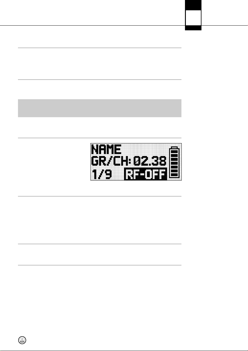
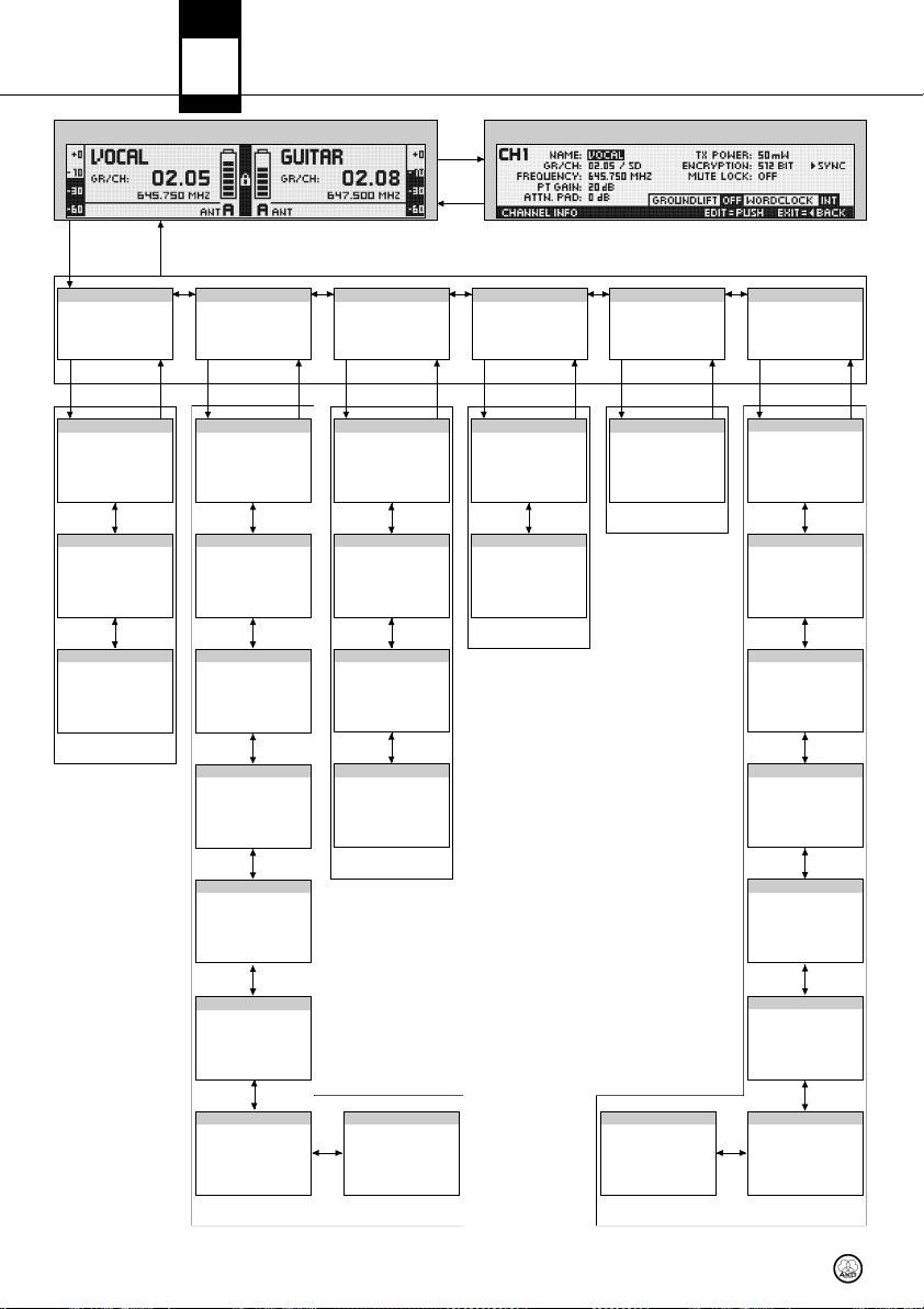
The general window shows all necessary parameters foroperation. In addition to a freely-selectable
name, the current frequency, the current group and channel, you can check the audio level,the active antenna, and the remaining use time of the transmitter battery. In case of a critical fault condition (audio mute, low battery, audio clip) you will see a warning message.
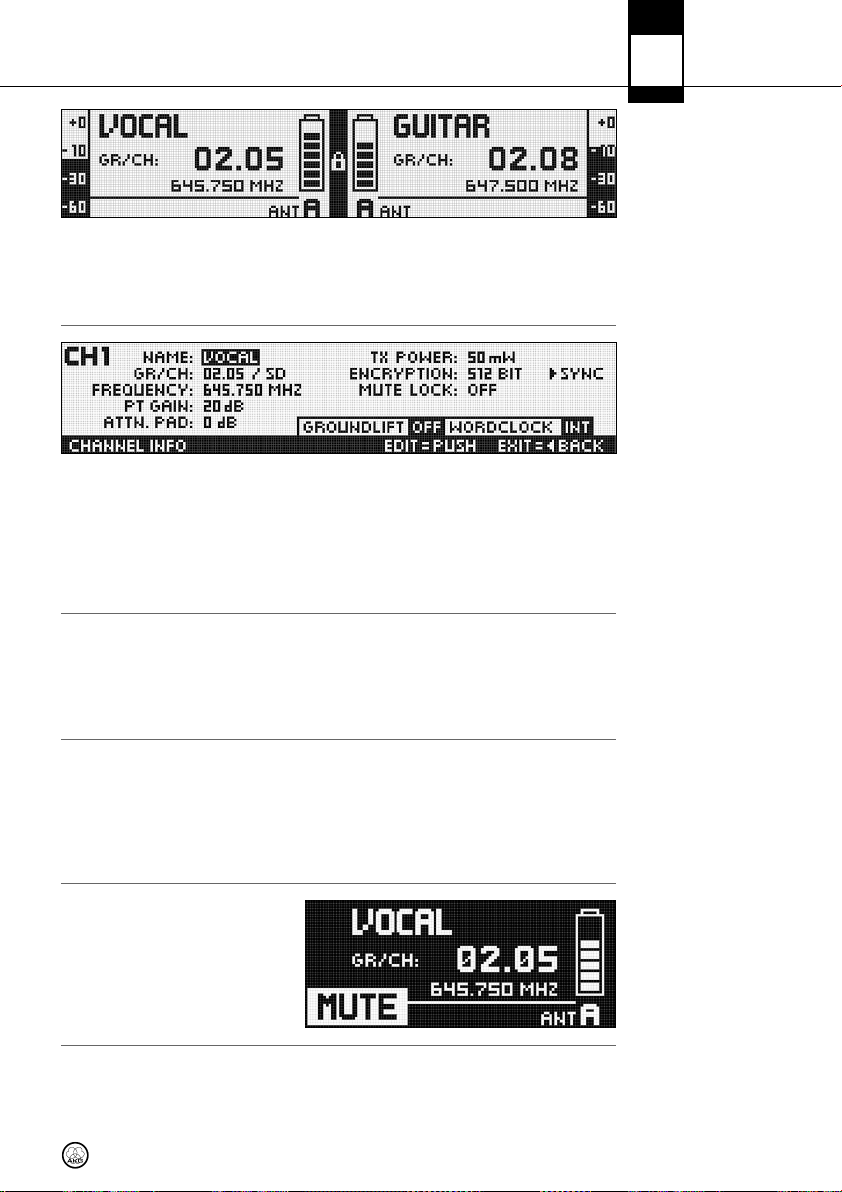
The Channel Information window provides a quick overview of the tuning parameters (group/channel, frequency,name, country, bodypack audio input gain,attenuation pad, transmission power, encryption, and mute lock). All these parameters can be set and synchronized.The GROUNDLIFT and
WORDCLOCK fields inidcate the related current status.
• To call up the channel information window, simply push the CH1 or CH2 button from the general window.
DMS
700
Main Window
Channel Information
Window
The battery symbols on the transmitter (C) and receiver (C) let you check the transmitter’s remaining battery capacity at aglance. Each segment equalsapproximately 1 hour of remaining battery life.
If no battery voltage is detected or the information is invalid,no information is shown on the display.
Approximately 1 hour before the battery will be dead the “LOW BATT” warning appears and the LED
ring turns red.
The audio meter (E) indicates the audio output level of the receiver.
• To match the receiver’s output level to the connected mixer, you can adjust the level using the
GAIN parameter in the AUDIO menu.
The outputlevel isnot properlyadjusted ifthe audiometer goesoff-scale orthe inputon the connected device is overloaded.
The audio outputis muted.The status LED
ring (11) is lit red.Since power and the RF
section remainON, no unwanted noise will
become audible from the sound system
when you mute the audio signal.
Battery Status
Indication
Audio Meter (E)
MUTE Indication (F)
11
Page 12
DMS
700
6 Display
Antenna Indication
Status & Warning
Messages
Status messages
in order of priority:
The DSR 700 receiveris a special digital true-diversity design with an integratedantenna splitter.The
antenna field (H) indicates the active antenna.
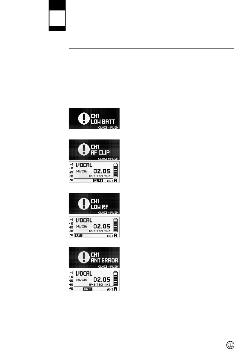
The statusand warningindication function provides visual warnings toalert youwhen selectablecritical system conditions occur. If one of the selected conditions occurs, the LED ring (11) around the
SELECT controlwill change from green to redand a warning message will appear on the displaythat
describes the current fault condition. The warning messages appear in the order of priority.
Depending on the type ofwarning, alarge message (upper field) isshown permanently or for 5 secs.
A small message (bottom line) is displayedfor as long asthe warning is not confirmed.The selected
warning functions are active in LOCK and ACTIVE modes.
• To delete a warning message from the display, press the SELECT control briefly.
1. LOW BATT: Transmitter battery capacity is low. The LED ring is
lit red and a large warning message displayed permanently.
2. AF CLIP: Audio overload in transmitter A/D converter. The LED
ring is lit red and a large warning message displayed for 5 secs.
or as long as the fault condition lasts.
A small warning message is displayed in the main window until
the warning is confirmed.
3. RF LOW: The field strength of the received RF signal is too low,
the receiver’s audio output is muted to prevent unwanted noise.
The LEDring is lit red and a large warning message displayed for
5 secs. or as long as the fault condition lasts.
A small warning message is displayed in the main window until
the warning is confirmed.
4. ANT ERROR: The same antenna has been active for more than
one minute.The LED ring is lit red and a large warning message
displayed for 5 secs. or as long as the fault condition lasts.
A small warning message is displayed in the main window until
the warning is confirmed.
12
Page 13
6 Display
DMS
700
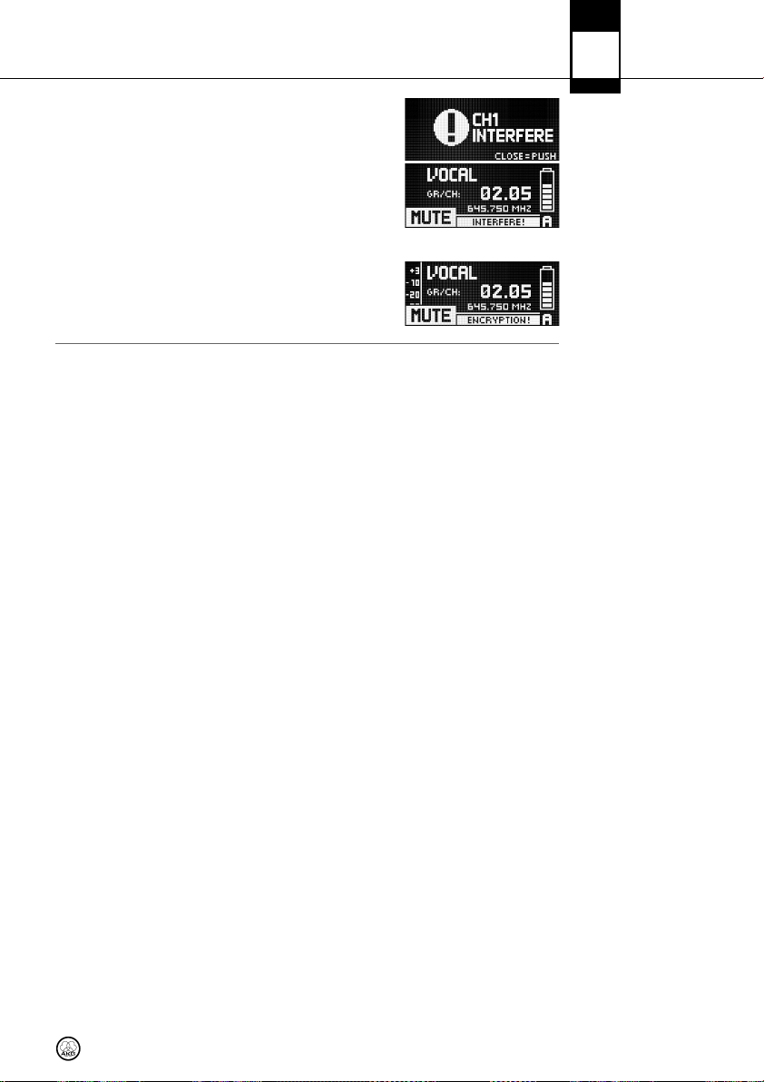
1. INTERFERE: Signal interference from other wireless systems,
TV, radio, CB radios, or defective electrical appliances or installations has been detected.
2. ENCRYPTION: The Encryption scheme has not been set properly.
Warning messages
in order of priority:
13
Page 14
DMS
700
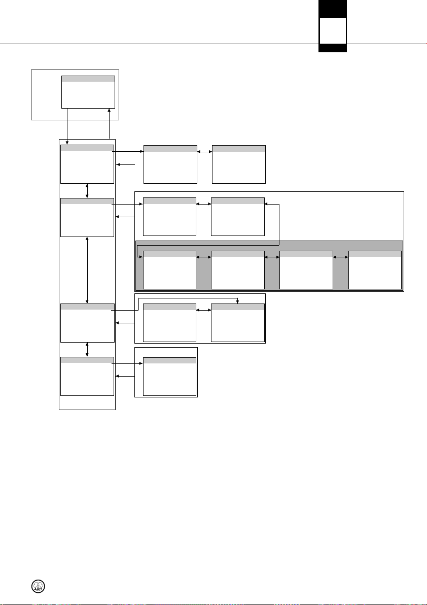
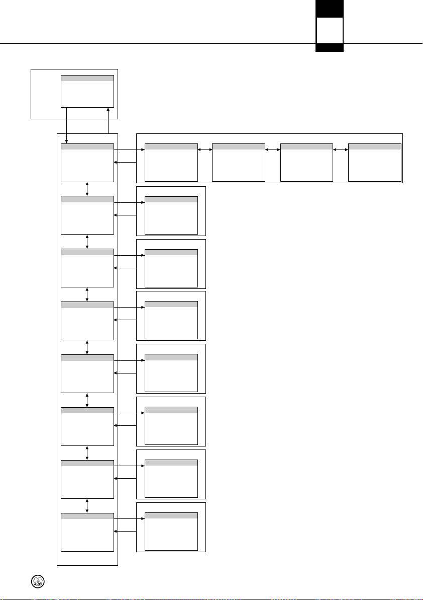
7 DSR 700 Menu
SELE CT BAC K
QUI CK SE TUP
Sea rchin g and s ettin g
clea n car rier fr equen cies
SELE CT BAC K
START SETUP
Sca nning th e ch annel
gro ups t o fin d, set , and
sync hron ize cl ean cha nnels
< >
CHA NNEL LI ST
List o f la st sc an re sults
< >
CON TINUE S CAN
Sta rt a ne w sca n to fi nd
ano ther se t of cle an
chan nels
QUI CK SE TUP M ENU
AIN WIND OW
M
< > < > < > < > < >
CHA NNEL
Set ting par amet ers
man ually
Syn chron ize c hanne l
SELE CT BAC K SELE CT BAC K SELE CT BACK S ELEC T BACK S ELECT B ACK
GRO UP/CH ANNEL
Set ting gro up a nd ch annel
man ually
< >
FRE QUENC Y
Set ting fr equen cy
man ually
< >
NAM E
Assi gnin g a n ame t o the
sele cted ch anne l
< >
PT GA IN
Set ting DPT 7 00 au dio
inpu t ga in
Set ting aud io e ffect s:
gain , low c ut, EQ ,
com press or, and li mite r
Set ting inp ut l evel to DS P
chai n
Set ting aud io e ffect s
ATTE NUATIO N PAD
Set ting aud io o utput l evel
HP GA IN
Adju stin g hea dphon e
vol ume
AUD IO
AIN
G
DSP
CH 1/ CH2
BA CK
ENV IR. SC AN
Sea rchin g fre quenc y ban d
for ac tive ra dio
fre quenc ies
UNL IMITE D SCA N
Sea rchin g ent ire
fre quency b and
< >
LIM IT SC AN
Lim it se arch to se lect able
par t of fr equen cy ban d
>
<
< >
ENV IR. SC AN ME NU
HAN NEL I NFORMATIO N WINDOW
C
Chec king RF r ecept ion
are a
START CHECK
Chec king RF r ecept ion
are a
< >
REH EARSA L MEN U
REH EARSA L
Gen eral se tting s
Pro gramm ing v isual
war nings fo r cr itica l
cond itio ns
Set ting spe cial fr eque ncy
pre sets
Turni ng au toma tic l ockin g
func tion ON o r OFF
Chan ging di spla y
app earan ce
UTI LITY
TATUS
S
< >
COU NTRY
>
<
AUT OLOCK
< >
DIS PLAY M ODE
< >
TRA NSM. P OWER
Set ting tr ansmi tter
RF out put p ower
< >
ENC RYPTI ON
Sel ectin g enc rypti on ke y:
OFF /32-b it/51 2-bit
< >
MUT E LOC K
Dea ctiva te th e tra nsmit ter
audi o mu te bu tton
< >
CHA NNEL ME NU
AUD IO ME NU
SYNCHR .TRANSMITT ER
Trans fer a ll se lecte d
val ues t o the t ransm itter
via in frar ed
WARN ING LI ST
Las t 25 war ning s
< >
UTI LITY ME NU
< >
DIS PLAY C ONTRA ST
Chan ging di spla y con trast
< >
FACT ORY R ESET
Rese ttin g all p arame ters
to the ir d efaul t val ues
< >
INF O
Call ing up so ftwar e an d
har dware in form ation
14
Page 15
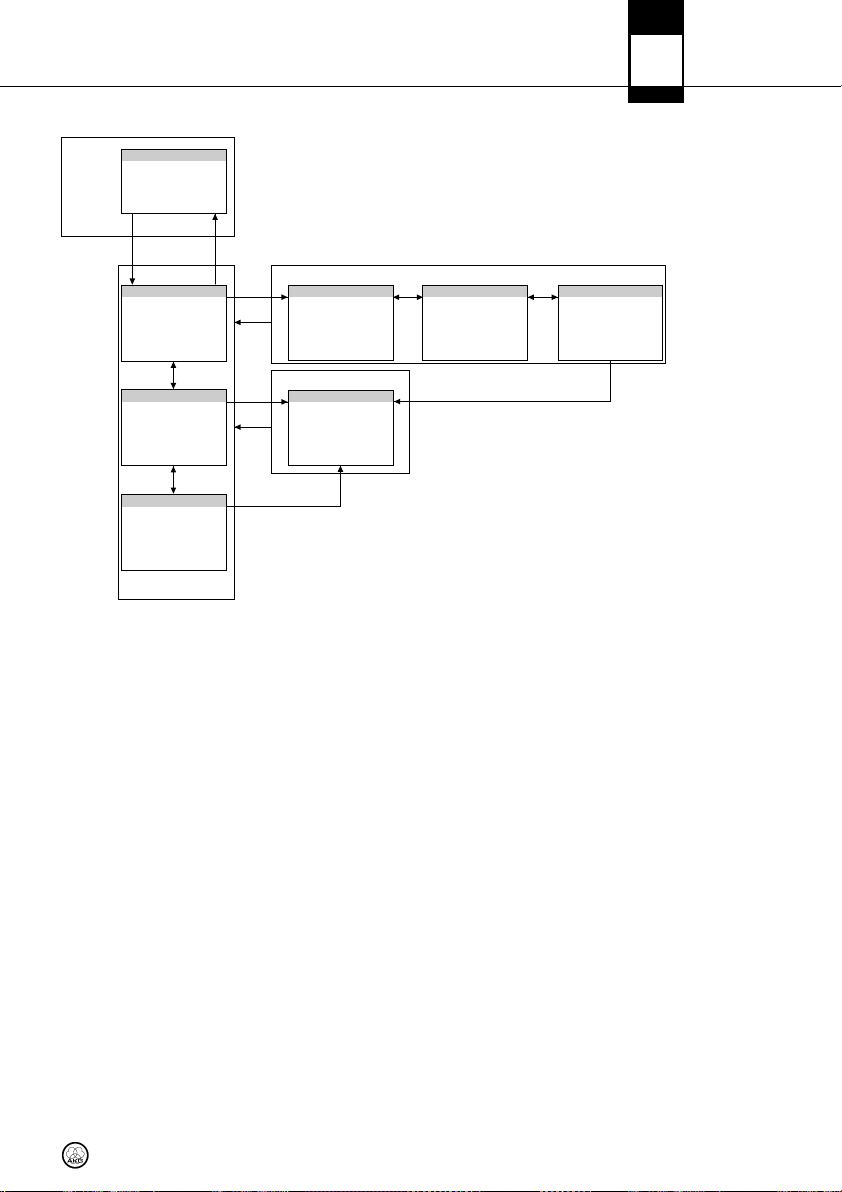
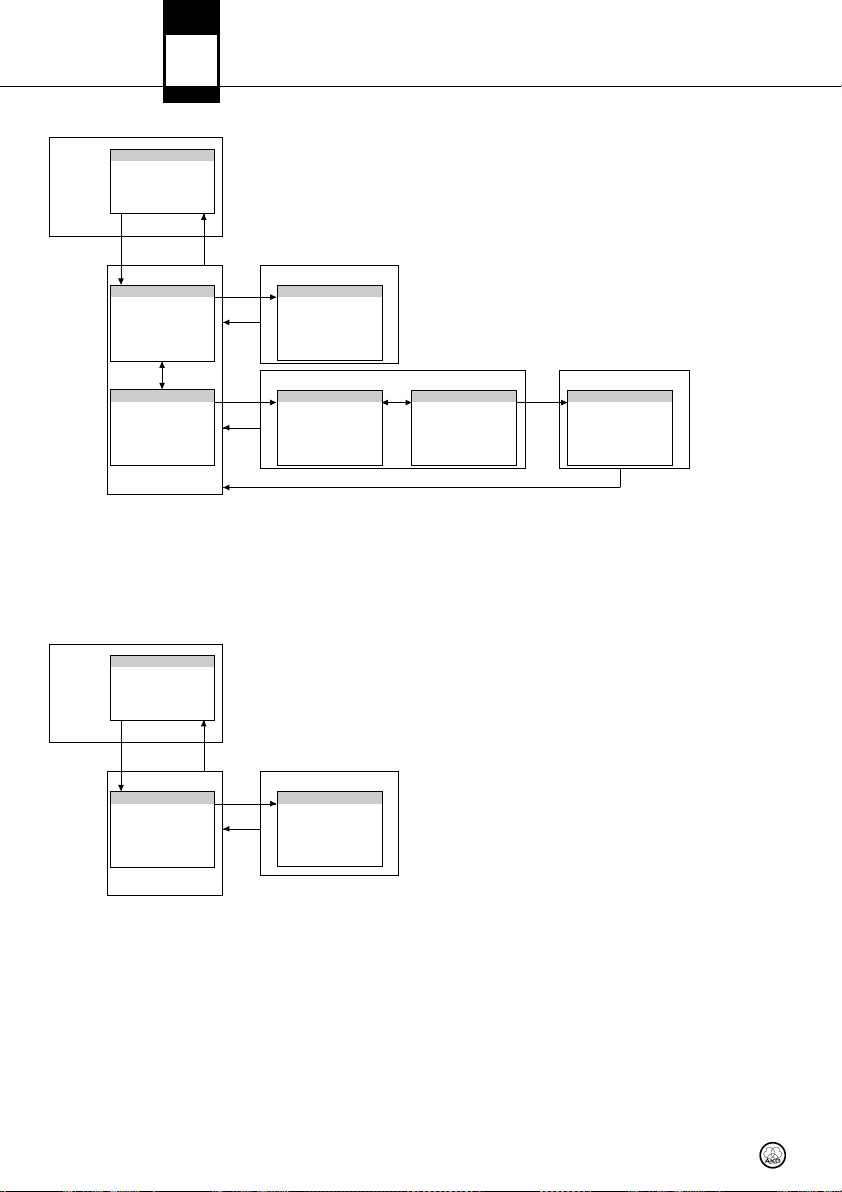
QUICK SETUP
QUI CK SE TUP
Sea rchin g and s ettin g
clea n car rier fr equen cies
MEN U
SELE CT BAC K
7 DSR 700 Menu
DMS
700
START SETUP
Sca nning th e ch annel
gro ups t o fin d, set a nd
sync hron ize cl ean cha nnels
< >
CHA NNEL LI ST
ist of l ast s can r esul t
L
>
<
CON TINUE S CAN
Sta rt a ne w sca n to fi nd
ano ther se t of cle an
chan nels
UIC K SET UP ME NU
Q
SELE CT
BA CK
SELE CT
BA CK
SELE CT
NO. CH ANNEL S
Numb er o f req uired
chan nels
ELEC T: sele ct/s tore va lue
S
< > : Numb er
CHA NNEL LI ST
List o f cle an ch annel s
SEL ECT: sho w fr equen cies
< > : Chan nel
CH1/ CH2: as sign ch annel
and sy nchro nize
< >
LIM IT FR EQ.. R ANGE
Lim it sc annin g fre quenc y
ran ge
ELEC T: sele ct/s tore va lue
S
< > : Freq uenci es
< >
START SCAN
Sta rt ne w sca n
SEL ECT: sta rt
15
Page 16
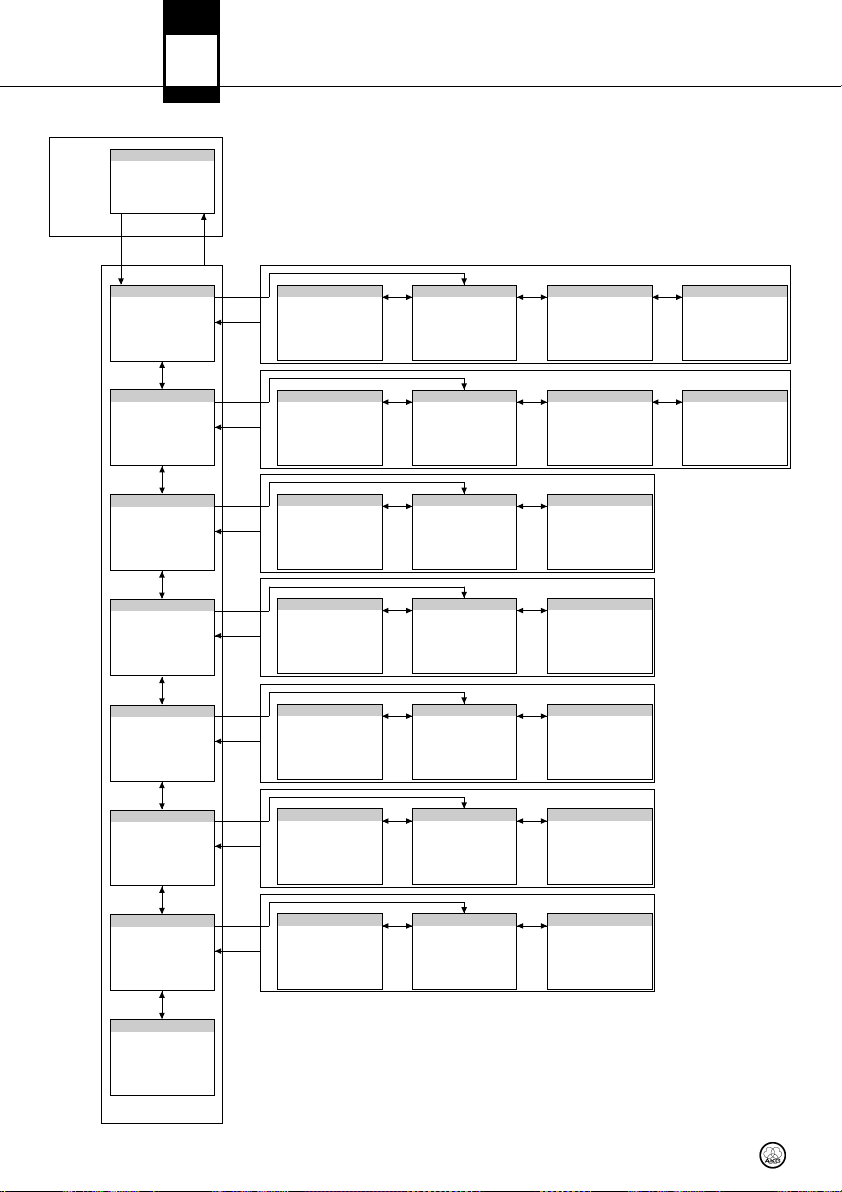
CHANNEL
MEN U
DMS
700
CHA NNEL
Set ting par amet ers
man ually
Syn chron ize c hanne l
SELE CT BAC K
7 DSR 700 Menu
GRO UP/CH ANNEL
Set ting gro up a nd ch annel
man ually
< >
FRE QUENC Y
ett ing f reque ncy
S
man ually
>
<
NAM E
Assi gnin g a n ame t o the
sele cted ch anne l
< >
T G AIN
P
Set ting DPT 7 00 au dio
inpu t ga in
< >
TRA NSM. P OWER
Set ting tr ansmi tter RF
out put p ower
< >
ENC RYPTI ON
Sel ectin g enc rypti on ke y:
OFF /32-b it/51 2-bit
SELE CT
CH1, CH 2
BA CK
SELE CT
CH1, CH 2
BA CK
SELE CT
H1, CH2
C
BA CK
SELE CT
CH1, CH 2
BA CK
SELE CT
CH1, CH 2
BA CK
SELE CT
CH1, CH 2
BA CK
CH1 /CH2
Sel ectin g cur rent ch annel
SEL ECT: sel ect/ store v alue
>: C H1/CH 2
<
CH1 /CH2
Sel ectin g cur rent ch annel
SEL ECT: sel ect/ store v alue
< > : CH1/ CH2
CH1 /CH2
ele cting cu rren t cha nnel
S
SEL ECT: sel ect/ store v alue
< > : CH1/ CH2
H1/ CH2
C
Sel ectin g cur rent ch annel
SEL ECT: sel ect/ store v alue
< > : CH1/ CH2
CH1 /CH2
Sel ectin g cur rent ch annel
SEL ECT: sel ect/ store v alue
< > : CH1/ CH2
CH1 /CH2
Sel ectin g cur rent ch annel
SEL ECT: sel ect/ store v alue
< > : CH1/ CH2
SELECT
< >
Sel ectin g gro up
SEL ECT: sel ect
>: G roup
<
SELECT
< >
Sel ectin g fre quenc y
SEL ECT: sel ect
< > : MHz
SELECT
< >
0 ch arac ters
1
SEL ECT: sel ect/ store
< > : Char acter
SELECT
< >
Sel ectin g aud io in put g ain
SEL ECT: sel ect/ store v alue
< > : 0, +1 0, +2 0 dB
SELECT
TRA NSM. P OWER
< >
Sel ectin g tra nsmit ter
RF out put p ower
SEL ECT: sel ect/ store
< > : RF p ower
SELECT
ENC RYPTI ON
< >
Sel ectin g enc rypti on ke y
SEL ECT: sel ect/ store v alue
< > : OFF/ 32-bi t/512 -bit
GRO UP
MHz
NAM E
T G AIN
P
SELECT
< >
Sel ectin g cha nnel
SEL ECT: sel ect/ store
>: C hanne l
<
SELECT
< >
Sel ectin g fre quenc y
SEL ECT: sel ect/ store
< > : kHz
SELECT
< >
ynch roni zing tr ansmi tter
S
SEL ECT: Sta rt
SELECT
< >
Syn chron izing t ransm itter
SEL ECT: Sta rt
SELECT
< >
Syn chron izing t ransm itter
SEL ECT: Sta rt
SELECT
< >
Syn chron izing t ransm itter
SEL ECT: Sta rt
CHA NNEL
KHz
SYN C
YNC
S
SYN C
SYN C
SELECT
< >
Syn chron izing t ransm itter
SEL ECT: Sta rt
SELECT
< >
Syn chron izing t ransm itter
SEL ECT: Sta rt
SYN C
SYN C
< >
MUT E LOC K
Dea ctiva ting th e
tra nsmit ter a udio mu te
butt on
< >
SYNCHR .TRANSMITT ER
Trans fer a ll se lecte d
val ues t o the t ransm itter
via in frar ed
SELE CT
CH1, CH 2
BA CK
CH1 /CH2
Sel ectin g cur rent ch annel
SEL ECT: sel ect/ store v alue
< > : CH1/ CH2
SELECT
< >
Dea ctiva te/ov errid e
tra nsmit ter m ute b utton
SEL ECT: sel ect/ store
< > : ON/O FF
MUT E LOC K
SELECT
< >
Syn chron izing t ransm itter
SEL ECT: Sta rt
SYN C
CHA NNEL ME NU
16
Page 17
AUDIO
MEN U
AUD IO
Set ting aud io e ffect s:
gain , low c ut, EQ ,
com press or, and li mite r
SELE CT BAC K
7 DSR 700 Menu
DMS
700
AIN
G
Set ting inp ut l evel to DS P
hain
c
< >
DSP
Set ting aud io e ffect s
>
<
TTE NUATIO N PAD
A
Set ting aud io o utput l evel
< >
HP GA IN
Adju stin g hea dphon e
vol ume
AUD IO ME NU
SELE CT
CH1, CH 2
BA CK
SELE CT
H1, CH2
C
BA CK
SELE CT
CH1, CH 2
BA CK
SELE CT
CH1, CH 2
BA CK
CH1 /CH2
Sel ectin g cur rent ch annel
SEL ECT: sel ect/ store v alue
< > : CH1/ CH2
PRO FILE
Sel ectin g pro file
SEL ECT: sel ect/ store
< > : Prof ile
OW CU T
L
Set ting lo w cut f reque ncy
SEL ECT: sel ect/ store
< > : Freq uency
CH1 /CH2
Sel ectin g cur rent ch annel
SEL ECT: sel ect/ store
< > : CH1/ CH2
HP LE VEL
Adju stin g hea dphon e
vol ume
SEL ECT: sel ect/ store
< > : Leve l
SELECT
< >
Adju stin g inp ut le vel t o
DSP (a udio) c hain
SEL ECT: sel ect/ store
< > : Gain
SELECT
>
<
Sto ring DSP s ettin gs i n a
pro file wit h a nam e
SEL ECT: sel ect/ store
< > : Prof ile & c harac ter
SELECT
< >
Set ting 3 B and EQ
SEL ECT: sel ect/ store
< > : Leve l & f reque ncy
SELECT
ATTE NUATIO N PAD
>
<
Sel ectin g aud io ou tput
gain
SEL ECT: sel ect/ store
< > : 0dB/ -30dB
GAI N
SAV E
SELECT
>
<
SELECT
Q
E
OMP RESSO R
C
< >
Set ting gai n, th resho ld,
rat io, at tack , and re lease
SEL ECT: sel ect/ store
< > : Value
SELECT
< >
DSP
IMI TER
L
Set ting thr esho ld
SEL ECT: sel ect/ store
< > : Value
17
Page 18
ENVIR. SCAN
ENV IR. SC AN
Sea rchin g fre quenc y ban d
for ac tive ra dio
MEN U
fre quenc ies
SELE CT BAC K
DMS
700
7 DSR 700 Menu
UNL IMITE D SCA N
Sea rchin g ent ire
fre quency b and
imit s earch t o sel ecta ble
L
par t of fr equen cy ban d
ENV IR. SC AN ME NU
REHEARSAL
Chec king RF r ecept ion
are a
MEN U
SELE CT BAC K
Chec king RF r ecept ion
are a
< >
LIM IT SC AN
REH EARSA L
START CHECK
SELE CT
BA CK
SELE CT SELE CT
BA CK
SELE CT
BA CK
GRA PH
Sca n act ive
SEL ECT: Zoo m
>: N aviga te
<
LIM IT FR EQ. RA NGE
Lim it fr equen cy ra nge
SEL ECT: sel ect & s tore
< > : Freq uency
GRA PH
Sca nning CH 1& CH2
SEL ECT: Zoo m
< > : Navi gate
CH1, C H2: se lect ch annel
< >
START SCAN
Sta rt ne w sca n
SEL ECT: Sta rt
GRA PH
Sca n act ive
SEL ECT: Zoo m
< > : Navi gate
BA CK
REH EARSA L MEN U
18
Page 19
UTILITY
MEN U
UTI LITY
Gen eral se tting s
SELE CT BAC K
7 DSR 700 Menu
DMS
700
STATU S
Pro gramm ing v isual
war nings fo r cr itica l
cond itio ns
< >
AUT OLOCK
urni ng a utoma tic l ockin g
T
func tion ON o r OFF
< >
OUN TRY
C
Set ting spe cial fr eque ncy
pre sets
< >
DIS PLAY M ODE
Chan ging di spla y
app earan ce
< >
DIS PLAY C ONTRA ST
Chan ging di spla y con trast
< >
FACT ORY R ESET
Rese ttin g all p arame ters
to the ir d efaul t val ues
ELE CT
S
BA CK
SELE CT
BA CK
SELE CT
BA CK
SELE CT
BA CK
SELE CT
BA CK
SELE CT
BA CK
RF LO W
Warn ing: no tr ansmi tter
RF sig nal r ecei ved
ELEC T: sele ct/s tore
S
< > : ON/O FF
AUT OLOCK
Turni ng au toma tic l ockin g
func tion ON o r OFF
SEL ECT: sel ect/ store
< > : ON/O FF
OUN TRY
C
Set ting sta ndar d or
peci al f reque ncy p reset s
s
SEL ECT: sel ect/ store
< > : Coun try
DIS PLAY M ODE
Swit chin g bet ween
4 di fffe rent wi ndows
SEL ECT: sel ect/ store
< > : Mode
DIS PLAY C ONTRA ST
Sel ectin g dis play co ntras t
SEL ECT: sel ect/ store
< > : Value
FACT ORY R ESET
Rese ttin g all p arame ters
to the ir d efaul t val ues
< > : YES/ NO
SELECT
< >
Warn ing: tra nsmi tter re mai ning ba ttery c apaci ty
s lo w
i
SEL ECT: sel ect/ store
< > : ON/O FF
LOW B ATT
SELECT
< >
Warn ing: aud io o verlo ad
at tr ansmi tter A /D
onv erter i nput
c
SEL ECT: sel ect/ store
< > : ON/O FF
AUD IO CL IP
SELECT
< >
Warn ing: ant enna in put
pro blem on re ceive r
ELEC T: sele ct/s tore
S
< > : ON/O FF
ANT E RROR
< >
INF O
Call ing up so ftwar e an d
har dware in form ation
< >
WARN ING LI ST
Las t 25 war ning s
UTI LITY ME NU
SELE CT
BA CK
SELE CT
BA CK
INF O
Sof tware a nd ha rdwar e
ver sion
WARN ING LI ST
< > : Navi gate
19
Page 20
DMS
700
Preset Mode
Frequency Mode
8 DPT 700 / DHT 700 Menus
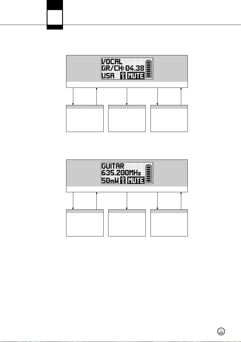
Standard Startup
ress ON/OFF button .
P
n sy nchr onizi ng a pr eset Gr oup & C hanne l, the d ispla y sho ws G R/CH an d the s elect ed co untry c ode.
O
MUT E Hold O N/O FFMUT E
UTE
M
Trans mitte r sen ds si gnal to m ute
ece iver au dio o utput .
r
GR/C H & Cou ntry s creen a ltern ates wi th Fr equen cy & Po wer
cre en.
s
HUT DOWN
S
Hol ding ON/ OFF wil l shu t do wn
he tra nsmit ter.
t
Warn ing
Even t
ARN ING
W
LOW BAT T or AUD IO C LIP
Pres s
ON/O FF
MUT E
or
n sy nchr onizi ng a ma nuall y-sel ected f reque ncy, th e dis play sh ows the s elect ed fr eque ncy an d RF ou tput le vel.
O
Pres s
ON/O FF
MUT E Hold O N/O FFMUT E
MUT E
Trans mitte r sen ds si gnal to m ute
rec eiver a udio out put.
SHU TDOWN
Hol ding ON/ OFF wil l shu t do wn
the tr ansm itter.
Warn ing
Even t
WARN ING
LOW BAT T or AUD IO C LIP
MUT E
or
20
Page 21
8 DPT 700 / DHT 700 Menus
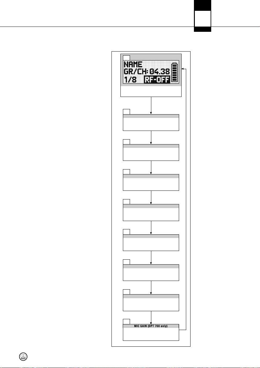
Silent Mode Startup
ress ON/OFF and MUTE buttons .
P
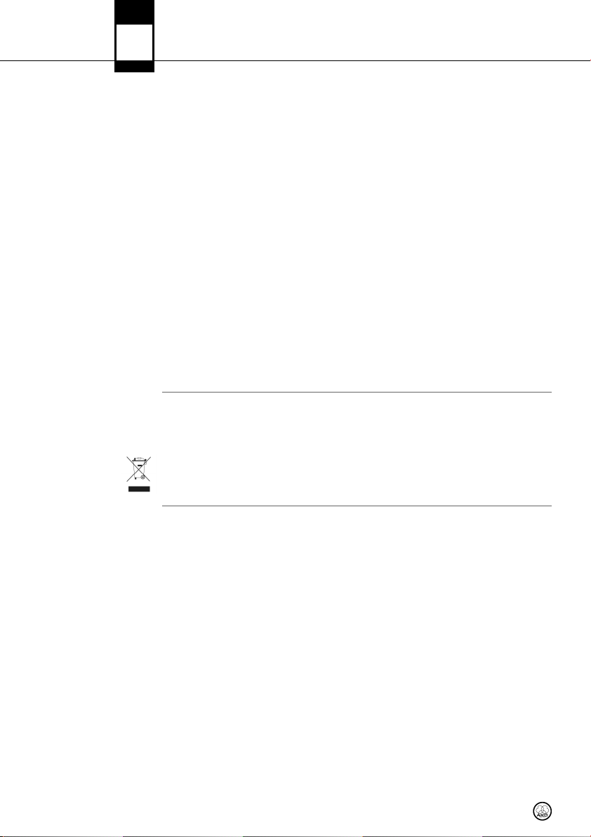
/9
1
Disp lay sho ws N AME a nd Gr oup/ Chan nel. De vice
oes no t tr ansmi t any d ata t o rec eive r (RF -OFF) .
d
MUT E
2/ 9
GRO UP/ CHANN EL
Disp lay sho ws g roup/ chann el an d fre quenc y.
(RF -OF F)
DMS
700
Silent Mode
3/ 9
Disp lay sho ws f reque ncy a nd co untry c ode.
(RF -OF F)
4/ 9
Disp lay sho ws c ountr y cod e an d ser ial
numb er.
(RF -OF F)
5/ 9
Disp lay sho ws s erial n umber a nd
sof tware v ersio n.
(RF -OF F)
6/ 9
Disp lay sho ws s oftwa re ve rsion .
(RF -OF F)
7/ 9
Disp lay sho ws h ardwa re ve rsion a nd
fre quency b and.
(RF -OF F)
8/ 9
Disp lay sho ws f reque ncy b and a nd tr ansmi tter
nam e.
(RF -OF F)
9/ 9
Disp lay sho ws m icrop hone ga in se tting .
(RF -OF F)
MUT E
REQ UENCY
F
MUT E
COU NTRY
UTE
M
SER IAL N UMBER
MUT E
SW VE RSION
MUT E
HW VE RSION
MUT E
BAN D
MUT E
MIC G AIN ( DPT 70 0 onl y)
INF O MEN U
MUT E
21
Page 22

DMS
700
9 Function Description
QUICK SETUP
CHANNEL Menu
GR OUP / CHANNEL
IImmppoorrttaanntt!!
TR ANS M. PO WER
!
L
FR EQU ENC Y
NA ME
PT GAIN
EN CRYPTION
For details, visit
www.akg.com.
The DSR 700 has been designed for use in large multi-channel systems. To find intermodulationfree and clean carrier frequencies quickly and easily, we recommend using the QUICK SETUP function to find all required channels.
1. To start QUICK SETUP, select the START SETUP menu, set the required number of channels as
well as the required frequency ranges and start scanning.
The scan procedure can take up to one minute. The CHANNEL LIST shows you clean channels
in a user-friendly list.
2. To assign and synchronize a clean channel to the receiver you can use the channel button.
3. Use the CONTINUE SCAN sub-menu to search for other frequencies.
All channel-specific parameters such as GROUP/CHANNEL, FREQUENCY, NAME, PT GAIN, TRANSMISSION POWER, ENCRYPTION and MUTE LOCK can be set and adjusted manually.
The DSR 700 receiver provides frequency groups with specially calculated frequencies. In the
GROUP/CHANNEL menu you can set and synchronize a channel (frequency) manually.
• Make certain that all selected channels are from the same Group within the same Preset. To find clean channels we recommend using the QUICK SETUP function.
The FREQUENCY sub-menu allows frequency adjustments in 25-kHz increments.
You can enter any name (the name of a performer or instrument, etc) for each channel.
This sub-menu allows you to match the audio input gain of the DPT 700 bodypack transmitter to the
microphone connected to the audio input.
The TRANSM.POWER sub-menu lets you adjust the RF output power of the synchronized transmitter.
If you turn on the encryption function, the receiver will calculate a unique key every time that you synchronize the transmitter. The receiver uploads the key during the infrared synchronization process.
You cannot read out the encryption key and it is not possible to set two transmitters to the same key.
MU TE LOC K
SY NCH R. T RAN SMI TTE R
22
• For transmitters with firmware versions lower than 2.0, select 32-bit encryption. (These trans-
Note:
mitters will not function with 512-bit encryption.)
• For transmitters with firmware version 2.0 and higher, you can select 512-bit encryption for
the highest possible security.
• If you use a backup transmitter you must turn off the signal encryption function.
MUTE LOCK deactivates the mute button on the transmitter. The user of the synchronized transmitter cannot mute the audio signal locally.
During the infrared synchronization process the receiver overwrites all previously selected transmitter settings (Group/Channel, frequency, name, bodypack gain, transmission power, encryption key,
and mute lock).
• To program the transmitter to the settings you selected on the receiver, start the transmitter synchronization from the receiver menu and point the infrared sensor (4) on the transmitter at the
infrared emitter (8) on the receiver from a distance of 4 inches/10 cm max.
Page 23
9 Function Description
DMS
700
GAIN allows you to set the the input level to the DSP audio processing section.
The built-in digital signal processor with several processing functions lets you control your audio sig-
GA IN
DS P
nal directly from the receiver. The following dynamics processors are available:
• Low Cut (frequency: 10 to 300 Hz))
• 3-band Equalizer (low frrequencies: ±20 dB, 80 Hz shelving; mid frequencies: ±20 dB, 100 Hz
to 10 kHz, Q = 2 parametric; high frequencies: ±20 dB, 8 kHz shelving)
• dbx®Compressor (threshold: -60 to 9 dBV; ratio: 1:1 to 1:10; gain: 0 to 20 dB: attack: 1 to
100 msecs.; release: 1 to 2000 msecs.)
• dbx®Limiter (threshold: -20 to 9 dBV)
All settings can be stored together with a freely selectable name in one of nine DSP Profiles.
AUDIO Menu
• Profile changes apply to both channels. All settings previously stored in a Profile will
be overwritten.
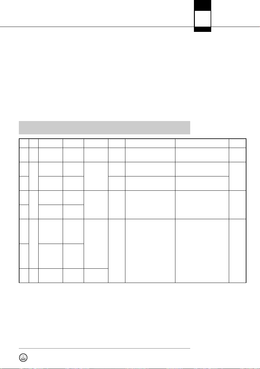
LOW CUT EQ COMPRESSOR LIMITER
Freq.
No. Profile Name Application
1
2 Head-worn Present PT 40 OFF -25 1.5:1 56207
3
4 Head-worn Music PT
Handheld Present HT
Presenter
Handheld Music HT
Music
Inexperienced
users,
PowerPoint,
places
of worship,
presenters
Experts,
vocalists,
rock bands,
Karaoke,
musical
Low Mid MidFreq High
[Hz]
dB] [dB] [kHz] [dB]
77 00 1.0 3.0 -30 2.1:1 31 71
40 OFF OFF 9
Threshold Ratio Gain Attack Release
[dB] [kHz] [ms] [ms]
!
L
IImmppoorrttaanntt!!
Threshold
[dB]
0
Beginners and
experts,
trumpet,
tuba,
drums
El. guitar,
bass guitar, ac-
tive acoustic
guitar
OFF OFF OFF 9
7 - 9
Instrument
5
6
microphone
w/bodypack
Instrument
Guitar
w/bodypack
–
User User 1 - 3 –
Instru PT
Guitar PT
DS P P rof ile s - Fa cto ry Def aul t S ett ing s
The DSP button provides a bypass function for LOW CUT, EQ, COMPRESSOR and LIMITER for each
channel separately.
Matches the receiver’s BALANCED output level to the input gain of the connected equipment . If you
are using a MIC input on your mixer, the 0 dB level might overload the input. In that case, set the receiver’s ATTENUATION PAD to -30 dB to reduce the output level.
The UNBALANCED line output level is not adjustable.
DS P B utt on
ATTENUAT ION PAD
23
Page 24
DMS
700
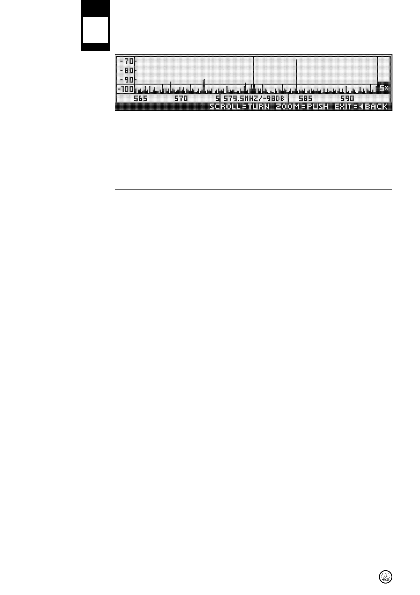
ENVIRONMENT SCAN
9 Function Description
The Environment Scan function turns the receiver into a spectrum analyzer. UNLIMITED SCAN automatically searches the receiver's entire frequency band ±6 MHz for active radio frequencies. LIMIT
SCAN scans only part of the receiver’s frequency range. During the search, the audio output is muted
and the display shows a frequency graph.
• You can navigate (CW, CCW) and zoom (push) through the graph using the SELECT control.
REHEARSAL –
Sound Check
UTILITY Menu
STATU S
Status indications
in order of priority:
The Rehearsal Scan function converts the receiver to an RF recorder to check the transmitter RF level
in your reception area. Maximum recording time is four minutes.
1. Start this function and walk around the desired coverage area with the synchronized transmitter. The graphic display indicates the received signal level as it varies over time.
2. To mark some positions, you can use the transmitter MUTE button to set markers on the receiver display.
• You can navigate (CW, CCW) and zoom (push) through the graph using the SELECT control.
• The received signal level should never drop below -85 dBm. You can optimize signal reception
by changing the position of the connected antennas.
The STATUS sub-menu lets you activate a visual warning that alerts you of selected critical system
conditions. If one of the selected conditions occurs, the LED ring around the SELECT control will
change from green to red and a warning message will appear on the display that describes the problem condition. The warning messages appear in the order of priority.
The LED ring is lit red and a large warning message displayed for 5 secs or as long as the fault condition lasts.
A small warning message is displayed until the warning is confirmed.
The selected warning functions are active in LOCK and ACTIVE modes.
• To delete a warning message from the display, press the SELECT control briefly.
LOW BATT: The transmitter’s remaining battery capacity is low. A large warning message is dis-
played permanently and the LED ring is lit red.
AF CLIP: Audio overload in transmitter A/D converter. The LED ring is lit red and a large warning mes-
sage displayed for 5 secs. or as long as the fault condition lasts.
A small warning message is displayed in the main window until the warning is confirmed.
• Reduce the audio input level.
RF LOW: The field strength of the received RF signal is so low that the receiver’s audio output is
muted to prevent unwanted noise. The LED ring is lit red and a large warning message displayed
for 5 secs. or as long as the fault condition lasts.
A small warning message is displayed in the main window until the warning is confirmed.
ANT ERROR: The same antenna has been active for at least two minutes. The LED ring is lit red and
a large warning message displayed for 5 secs.
A small warning message is displayed in the main window until the warning is confirmed.
• Check if an antenna cable is broken or incorrectly connected.
24
Page 25
9 Function Description
DMS
700
When you turn the receiver on for the first time, the receiver will ask you to select a country.
• From the UTILITY - COUNTRY menu, you should normally select SD (Standard), EU (EUROPE), or
US (USA).
• For some specific countries, you may have to choose one of the internally-stored frequency presets.
• For all other countries, use the SD setting.
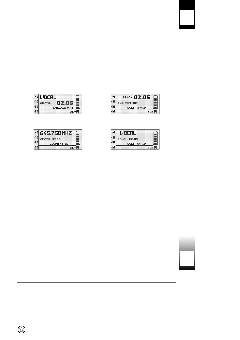
This menu lets you change the display appearance. You can choose from four different displays:
MAIN GROUP/CHANNEL
FREQUENCY NAME
The DISPLAY CONTRAST sub-menu allows you to adjust the contrast of the display for use in varying lighting conditions.
The FACTORY RESET sub-menu allows you to reset all parameters to their default values.
CO UNT RY
DI SPL AY MODE
DI SPL AY CONTRAST
FACT ORY RESET
The INFO sub-menu lets you call up software information about your receiver and the transmitter synchronized to it.
WARNING LIST stores the last 25 warnings.
10 Cleaning
• Use a soft cloth moistened with water to clean the surfaces of the equipment.
IN FO
WARNING LIST
DMS
700
25
Page 26
DMS
700
11 Troubleshooting
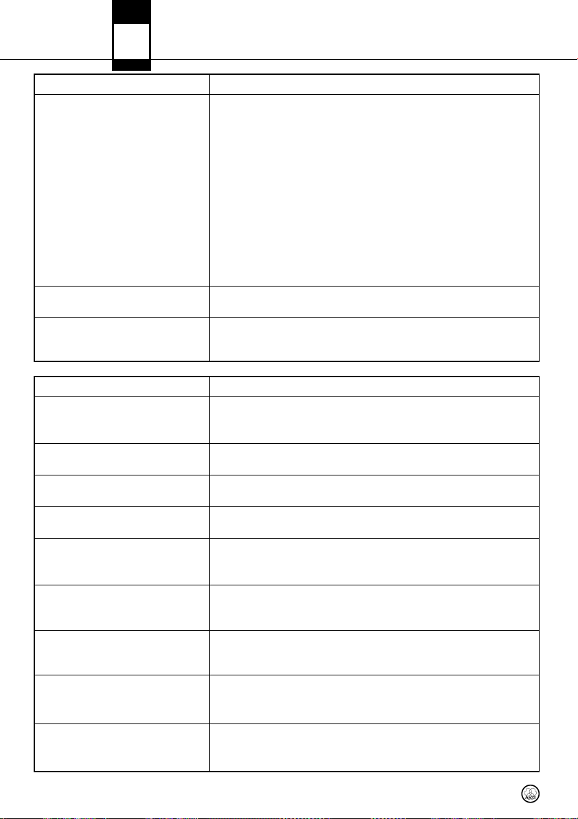
Problem Possible Cause / Remedy
• Interference from other wireless systems, TV, radio, CB radios, defective electrical appliances or wiring.
• Transmitter is tuned to different frequency than receiver.
• Transmitter is "OFF" or transmitter MUTE switch set to "MUTE".
• Power cord is not connected to receiver and/or power outlet.
• Receiver is OFF.
No sound.
Distortion.
Momentary loss of sound ("dropouts")
at some points within performance
area.
Status/Error/Warning Message Problem / Remedy
RF LOW
AF CLIP
ANT ERROR
LOW BATT
SYSTEM ERRROR
RF ERROR, PLL ERROR
UPDATE FIRMWARE
INTERFERE ERROR
ENCRYPTION!
• Receiver is not connected to sound system.
• Microphone or instrument is not connected to bodypack transmitter.
• Transmitter batteries are not inserted properly.
• Transmitter batteries are dead.
• Transmitter is too far away from receiver.
• Obstructions between transmitter and receiver are blocking the signal.
• Receiver is invisible from transmitter location.
• Receiver too close to metal objects.
• Software versions of the transmitter and receiver do not match.
• Gain settings are too low or too high.
• DSP functions are not set properly.
• Relocate receiver or re-orient the antennas. If dead spots persist, mark and
avoid them.
• Transmitter is too far away from receiver.
• The field strength of the received RF signal is so low that the receiver audio
output is muted to prevent unwanted noise.
- Re-locate receiver or use remote antennas.
• Audio overload in transmitter A/D converter.
- Reduce audio input level.
• The same antenna has been active for at least two minutes.
- Check if antenna cable(s) is/are broken or incorrectly connected.
• Transmitter battery capacity is low.
- Insert new batteries.
• Internal error.
- Switch power to receiver OFF and back ON after about 10 seconds. If the
problem persists, contact your AKG Service Center.
• Receiver cannot lock on to the selected frequency.
- Push SELECT briefly to confirm error and select a different frequency.
- If the problem persists, contact your AKG Service Center.
• System is ready for software update.
- Switch power to receiver OFF and back ON after about 10 seconds.
- If the problem persists, contact your AKG Service Center.
• Transmitter signal is being “jammed” by other wireless systems, TV, radio, CB
radios, or defective electrical appliances or installations.
- Change frequency or switch off interfering device.
• Encryption is not set properly.
- Synchronize transmitter.
• Interference from other DMS 700 transmitter.
26
Page 27

DMS
11 Troubleshooting
SYNC Messages Problem / Remedy
WRONG DEVICE • Transmitter frequency band does not match the receiver’s frequency band.
ERROR DEVICE
TIMEOUT • No infrared data detected.
• Error in transmitter ID data.
- If the problem occurs frequently, contact your AKG Service Center.
700
27
Page 28

DMS
700
12 Specifications
DMS 700 Digital
Microphone System
DSR 700 Digital
True Diversity Receiver
Carrier frequency range Band 1: 548.1 to 697.9 MHz
Switching bandwidth ≤ 155 MHz (depending on local regulations)
Audio bandwidth 25 Hz to 20 kHz (±3 dB)
T.H.D. ≤ 0.05 %
Signal/noise ratio (A-weighted) Analog: XLR balanced, typ. 115 dB(A)
Audio sampling rate 24 Bit / 44.1 kHz
Modulation Digital
Bit rate < 200 kbps
Compression AKG premium audio compression technology
Latency 3.5 msecs.
Encryption 32-bit, 512-bit selectable (no added latency)
Temperature range 14 to 131°F / -10 to 55°C
Carrier frequency range Band 1: 548.1 to 697.9 MHz
Switching Bandwidth ≤ 155 MHz (country dependent)
Channels 2 (Dual Receiver)
Sensitivity 10 dBµV / -97 dBm
Image & spurious rejection ≥ 95 dB
Receiver type Super heterodyne
Diversity system Digital true diversity
Antenna inputs 2 x 50-ohm BNC female connector
Audio outputs 2 x analog: balanced XLR
Audio output level
Low cut 10 to 300 Hz
Equalizer 3-band (parameters: LF gain, mid gain, mid frequency,
Compressor dbx®(parameters: gain, threshold, ratio, attack, release)
Limiter dbx®(parameter: threshold)
Transmitter battery meter 7-segment bargraph
PC interface
Power supply 90 to 240 VAC, 50 to 60 Hz, 0.4 A
Dimensions Standard 1U rack-mount case
Net weight 5.1 lbs. / 2.3 kg
Band 2: 710.1 to 864.9 MHz
Digital: AES-EBU, typ. 120 dB(A)
Band 2: 710.1 to 864.9 MHz
2 x analog: unbalanced ¼” jack
1 x digital: AES-EBU XLR (48 kHz) w/ BNC Wordclock IN
XLR balanced: +15 dBu (max.); 1/4" jack unbalanced: +9 dBu
HF gain)
Ethernet via HUB 4000 Q, HiQnet System Architect software
18.9(W) x 1.7(H) x 7.87(D )in. / 480(W) x 43(H) × 200(D) mm
DPT 700 Digital
Bodypack Transmitter
28
Carrier frequency range Band 1: 548.1 to 697.9 MHz
Band 2: 710.1 to 864.9 MHz
Switching bandwidth ≤ 155 MHz (country dependent)
RF output power 10, 20, 30, 50 mW (ERP max.),
software-adjustable (depending on local regulations)
Spurious ≤ -70 dBc
Antenna ¼- wave antenna
Audio input TB3M / 3-pin mini XLR socket (3 Vrms max.)
Audio input gain 0, +10, +20 dB selectable
Battery life ≥ 7 hours (2 x 1.5-V LR6 AA size batteries)
≥ 8 hours (2 x 1.2-V AA size NiMH >2100 mAh recharge
able batteries)
Dimensions 3.3(W )x 2.5(H) x 0.86(D ) in.
83.5(W) × 64.1(H) x 22(D) mm
Net weight 2.9 oz / 82 g without batteries
Page 29

DMS
700
Carrier frequency range Band 1: 548.1 to 697.9 MHz
Band 2: 710.1 to 864.9 MHz
Switching Bandwidth ≤ 155 MHz (country-dependent)
RF output power 10, 20, 30, 50 mW (ERP max.),
software-adjustable (depending on local regulations)
Spurious ≤ -70 dBc
Antenna Built-In helical antenna
Microphone element DHT 700 D5: dynamic microphone (supercardioid)
DHT 700 D7: dynamic microphone (supercardioid)
DHT 700 C5: condenser microphone (cardioid)
Max. SPL DHT 700 D5: ≤ 140 dB SPL
DHT 700 D7: ≤ 140 dB SPL
DHT 700 C5: ≤ 144 dB SPL
Battery life ≥ 7 hours (2 x 1.5-V LR6 AA batteries)
≥ 8 hours (2 x 1.2-V AA size NiMH >2100 mAh recharge
able batteries)
Dimensions 2(dia.) × 9.1(L) in. / 52(dia.) × 231(L) mm
Net weight 11.8 oz / 336 g
This product conforms to the standards listed in the Declaration of Conformity. To order a free
copy of the Declaration of Conformity, visit http://www.akg.com or contact sales@akg.com.
DHT 700 Digital
Handheld Transmitter
29
Page 30

DMS
700
Vielen Dank,
Verwendete Symbole
WWiicchhttiiggeerr HHiinnwweeiiss::
dass Sie sich für ein Produkt aus dem Hause AKG entschieden haben. Bitte lesen Sie die Bedienungsanleitung aufmerksam durch, bevor Sie das Gerät benützen, und bewahren Sie die Bedie-
nungsanleitung sorgfältig auf, damit Sie jederzeit nachschlagen können. Wir wünschen Ihnen viel
Spaß und Erfolg!
Der Blitz im gleichseitigen Dreieck bedeutet, dass im Gerät gefährliche Spannungen vor-
handen sind.
↯
L
Das Rufzeichen im gleichseitigen Dreieck am Gerät ist eine Aufforderung, die Bedie-
nungsanleitung zu lesen. In der Bedienungsanleitung kennzeichnet dieses Symbol Anwei-
!
L
sungen, die zum sicheren Betrieb des Geräts unbedingt zu befolgen sind.
• Die interne Firmware des Systems DMS 700 wird ständig verbessert, um Kundenan-
!
L
forderungen optimal gerecht zu werden. Sollte Ihr System bereits mit einer höheren
Firmware als der in dieser Bedienungsanleitung beschriebenen ausgestattet sein, können manche Funktionen von der Beschreibung abweichen.
• Die aktuelle Firmware-Version des Empfängers können Sie im Menü abrufen. Die in der
Bedienungsanleitung beschriebene Firmware-Version ist auf der Titelseite angegeben.
• Wir empfehlen, vor dem Weiterlesen zu überprüfen, ob die Firmware-Version des Empfängers mit der in der Bedienungsanleitung beschriebenen Version übereinstimmt.
Wenn dies nicht der Fall ist, finden Sie die jeweils neuesten Änderungen im Internet
unter www.akg.com
30
Page 31

Inhaltsverzeichnis
1 Sicherheit und Umwelt ...........................................................................................................32
Sicherheit.................................................................................................................................32
Umwelt ....................................................................................................................................32
2 Lieferumfang..........................................................................................................................33
3 Allgemeines............................................................................................................................34
DMS 700.................................................................................................................................34
4 Inbetriebnahme ......................................................................................................................36
Batterien in den Sender einlegen................................................................................................36
Antennen anschließen...............................................................................................................36
Empfänger positionieren............................................................................................................36
Empfänger an ein Mischpult/einen Verstärker anschließen ...........................................................36
Ground Lift (16, 19)...................................................................................................................37
Empfänger an das Stromnetz anschließen...................................................................................37
SILENT-Modus des Senders ......................................................................................................37
Lock-Modus (Tastensperre) des Empfängers ...............................................................................37
Externer MUTE-Schalter (optional) ..............................................................................................37
5 Bedienungshinweise ..............................................................................................................38
SELECT-Rad.............................................................................................................................38
Taste CH1, CH 2 (10 / 12) ..........................................................................................................38
BACK-Taste (4) .........................................................................................................................38
DSP-Taste (2) ...........................................................................................................................38
Audiosignal abhören - Taste Headphones CH1, CH 2 (6) ...............................................................38
6 Display....................................................................................................................................39
Hauptfenster ............................................................................................................................39
Kanalfenster.............................................................................................................................39
Batterieanzeige.........................................................................................................................39
Audiopegelanzeige (E)...............................................................................................................39
MUTE-Anzeige (F).....................................................................................................................39
Antennenanzeige......................................................................................................................40
Zustands- und Warnmeldungen .................................................................................................40
7 Menüstruktur DSR 700 ...........................................................................................................42
QUICK SETUP...........................................................................................................................43
CHANNEL.................................................................................................................................44
AUDIO......................................................................................................................................45
ENVIR. SCAN ............................................................................................................................46
REHEARSAL .............................................................................................................................46
UTILITY ....................................................................................................................................47
8 Menüstruktur DPT 700 / DHT 700 ...........................................................................................48
Einschalten im Normalbetrieb ....................................................................................................48
Einschalten im SILENT-Modus....................................................................................................49
9 Funktionsbeschreibung..........................................................................................................50
QUICK SETUP...........................................................................................................................50
CHANNEL.................................................................................................................................50
AUDIO......................................................................................................................................51
ENVIRONMENT SCAN................................................................................................................52
REHEARSAL - SOUND CHECK ....................................................................................................52
UTILITY ....................................................................................................................................52
10 Reinigung...............................................................................................................................53
11 Fehlerbehebung .....................................................................................................................54
12 Technische Daten ...................................................................................................................56
Systemdaten DMS 700 .............................................................................................................56
Digitaler True Diversity-Empfänger DSR 700................................................................................56
Digitaler Taschensender SPT 700...............................................................................................56
Digitaler Handsender DHT 700...................................................................................................57
DMS
700
31
Page 32

!
L
1 Sicherheit und Umwelt
Sicherheit
Umwelt
• Setzen Sie das Gerät nicht direkter Sonneneinstrahlung, starker Staub- und Feuchtigkeitseinwirkung, Regen, Vibrationen oder Schlägen aus.
• Schütten Sie keine Flüssigkeiten auf das Gerät und lassen Sie keine sonstigen Gegenstände
durch die Lüftungsschlitze in das Gerät fallen.
• Das Gerät darf nur in trockenen Räumen eingesetzt werden.
• Das Gerät darf nur von autorisiertem Fachpersonal geöffnet, gewartet und repariert werden. Im
Inneren des Gehäuses befinden sich keinerlei Teile, die vom Laien gewartet, repariert oder ausgetauscht werden können.
• Prüfen Sie vor Inbetriebnahme des Gerätes, ob die auf dem Gerät angegebene Betriebsspannung
der Netzspannung am Einsatzort entspricht.
• Betreiben Sie das Gerät ausschließlich an einer Netzspannung zwischen 90 und 240 V AC. Andere Stromarten und Spannungen könnten das Gerät ernsthaft beschädigen!
• Brechen Sie den Betrieb der Anlage sofort ab, wenn ein fester Gegenstand oder Flüssigkeit in
das Geräteinnere gelangen sollte. Ziehen Sie in diesem Fall sofort das Netzkabel des Netzgeräts
aus der Steckdose und lassen Sie das Gerät von unserem Kundendienst überprüfen.
• Stellen Sie das Gerät nicht in der Nähe von Wärmequellen wie z. B. Radiatoren, Heizungsrohren,
Verstärkern, usw. auf und setzen Sie es nicht direkter Sonneneinstrahlung, starker Staub- und
Feuchtigkeitseinwirkung, Regen, Vibrationen oder Schlägen aus.
• Verlegen Sie zur Vermeidung von Störungen bzw. Einstreuungen sämtliche Leitungen, speziell die
am Audioausgang, getrennt von Starkstromleitungen und Netzleitungen. Bei Verlegung in Schächten oder Kabelkanälen achten Sie darauf, die Übertragungsleitungen in einem separaten Kanal
unterzubringen.
• Reinigen Sie das Gerät nur mit einem feuchten, aber nicht nassen Tuch. Ziehen Sie unbedingt
das Netzkabel des Geräts vorher aus der Steckdose! Verwenden Sie keinesfalls scharfe oder
scheuernde Reinigungsmittel sowie keine, die Alkohol oder Lösungsmittel enthalten, da diese den
Lack sowie die Kunststoffteile beschädigen könnten.
• Verwenden Sie das Gerät nur für die in dieser Bedienungsanleitung beschriebenen Anwendungen. Für Schäden infolge unsachgemäßer Handhabung oder missbräuchlicher Verwendung kann
AKG keine Haftung übernehmen.
• Entsorgen Sie leere Batterien stets gemäß den jeweils geltenden Entsorgungsvorschriften. Werfen Sie Batterien keinesfalls ins Feuer (Explosionsgefahr) oder in den Hausmüll.
• Die Verpackung ist recyclierbar. Entsorgen Sie die Verpackung in einem dafür vorgesehenen
Sammelsystem.
• Wenn Sie das Gerät verschrotten, entfernen Sie die Batterien, trennen Sie Gehäuse, Elektronik
und Kabel und entsorgen Sie alle Komponenten gemäß den dafür geltenden Entsorgungsvorschriften.
32
Page 33

2 Lieferumfang
• Kontrollieren Sie bitte, ob die Verpackung alle unten angeführten Teile enthält. Falls etwas fehlt,
wenden Sie sich bitte an Ihren AKG-Händler.
DMS
700
• 1 x Empfänger DSR 700
• 2 x BNC UHF-Antennen
• 2 x Antennenkabel für Frontmontage 0110E01890
• 1 x Kaltgeräte-Netzkabel nach EU-Norm
• 1 x Kaltgeräte-Netzkabel nach US-Norm
• Taschensender DPT 700
• 2 x Batterien LR6 (Größe AA)
• Handsender DHT 700
• 2 x Batterien LR6 (Größe AA)
• Stativanschluss
• Windschutz
• CU 700 — Ladegerät für DPT 700 und DHT 700
• MK/GL — Gitarren/Instrumentenkabel
• W 3004 — Windschutz
• RMS 4000 — externen MUTE-Schalter
• Verschiedenen Mikrofone für DPT 700
• SRA 2 W — passive Richtantenne
• SRA 2 B/W — aktive Richtantenne
• RA 4000 W — passive Rundumantenne
• RA 4000 B/W — aktive Rundumantenne
• PS 4000 W — aktiver Antennensplitter
• AB 4000 — Antennenbooster
• MK PS — Antennenkabel, 65 cm
• MKA 20 — Antennenkabel, 20 m
• 0110E01890 — Antennenkabel für Frontmontage
DSR 700
DPT 700
DHT 500 D5, DHT D7,
DHT 700 C5
Optionales Zubehör
Antennenzubehör
• Weitere Optionen und Antennenzubehör finden Sie im aktuellen AKG-Katalog/Folder oder auf
www.akg.com. Ihr Händler berät Sie gerne.
33
Page 34

DMS
700
3 Allgemeines
DMS 700
DSR 700
Be die nel eme nte :
Siehe Seite i.
Das DMS 700 besteht aus dem digitalen stationären True Diversity-Empfänger DSR 700, den
Handsendern DHT 700 C5 mit AKG-Mikrofonkopf C 5, DHT 700 D7 mit AKG-Mikrofonkopf D 7,
DHT 700 D5 mit AKG-Mikrofonkopf D 5, sowie dem Taschensender DPT 700. Sowohl der Empfänger als auch die Sender arbeiten in einer Schaltbandbreite von bis zu 155 MHz im jeweiligen Frequenzset innerhalb eines UHF-Bands von 548 bis 865 MHz. Sie können die 'Empfangsfrequenz aus
den vorprogrammierten Frequenzgruppen und Subkanälen Ihres Empfängers auswählen oder in 25kHz-Schritten direkt einstellen. Sowohl der Hand- als auch der Taschensender werden via Infrarotübertragung auf die am Empfänger eingestellten Parameter programmiert.
1. POWER: Ein/Ausschalter
2. DSP-Taste
3. Display
4. BACK-Taste
5. SELECT-Rad (links/rechts drehen, drücken)
6. Kopfhörertasten (CH1, CH2)
7. Kopfhörerausgang: 6,3-mm-Klinkenbuchse
8. Infrarot-Sendefenster zur Datensynchronisation
9. HF-Pegelanzeige
10. Kanalwahltaste für Kanal CH1
11. Leuchtring zur Statusanzeige für Kanal CH1 und CH2 (rot = Warnung, grün = OK)
12. Kanalwahltaste für Kanal CH2
13. Öffnung für Antennen-Frontmontage
14. Antenneneingang A: BNC-Buchse
15. Antenneneingang B: BNC-Buchse
16. GROUND LIFT-Schalter für XLR-Ausgang von Kanal CH1
17. Symmetrischer analoger Audioausgang, Kanal CH1, an XLR-Buchse (männlich)
18. Unsymmetrischer analoger Audioausgang, Kanal CH1, an 6,3-mm-Klinkenbuchse
19. GROUND LIFT-Schalter für XLR-Ausgang von Kanal CH2
20. ymmetrischer analoger Audioausgang, Kanal CH2, an XLR-Buchse (männlich)
21. Unsymmetrischer analoger Audioausgang, Kanal CH2, an 6,3-mm-Klinkenbuchse
22. Datenschnittstelle: RJ11-Buchse zum Anschluss des Empfängers an einen Computer über
HUB 4000 Q
23. AES-EBU WORDCLOCK IN (48 kHz): BNC-Buchse
24. Digitaler AES-EBU Audioausgang, CH 1 und CH 2 (48 kHz), an XLR-Buchse (männlich)
25. Kaltgeräte-Netzanschluss (90 - 240 V AC)
Di spl ay:
Siehe Seite i.
34
A. Alphanumerische Namensanzeige
B. Aktuelle Gruppen- und Kanalnummer
C. 7-teilige Statusanzeige der Senderbatterie
D. Symbol für LOCK-Modus (Tastensperre)
E. Audiopegelanzeige
F. MUTE (Stummschaltungs-)-Symbol
G. Aktuelle Frequenz
H. Momentan aktive Antenne
Page 35

DMS
700
1. Display
2. MUTE-Schalter
3. λ/4-Antenne
4. Infrarot-Empfängerdiode zur Sendersynchronisation
5. Status-LED (rot = Warnung, grün = OK)
6. Ein/Ausschalter
7. Batteriefachdeckel
8. Audioeingang für Mikrofon oder Instrument: 3-pol. Mini-XLR-Buchse (TB3M)
9. Batteriefach für 2 LR6 (AA) 1,5-V-Batterien oder 1,2-V-NiMH-Akkus Größe AA (>2100 mAh)
10. 2,5-mm Klinkenbuchse für externen MUTE-Schalter
11. Ladekontakte
12. Verriegelungsknopf für Batteriefachdeckel
A. Alphanumerische Namensanzeige
B. Aktuelle Gruppen- und Kanalnummer
C. 7-teilige Statusanzeige der Senderbatterie
D. Ländercode oder HF-Pegel
E. Symbol für aktive Verschlüsselung
F. Symbol für aktivierte Stummschaltung
1. Display
2. MUTE-Schalter
3. Ladekontakte, Wendelantenne
4. Infrarot-Empfängerdiode zur Sendersynchronisation
5. Status-LED (rot = Warnung, grün = OK)
6. Ein/Ausschalter
7. Batteriefachdeckel
8. Mikrofonkopf
9. Batteriefach für 2 LR6 (AA) 1,5-V-Batterien oder 1,2-V-NiMH-Akkus Größe AA (>2100 mAh)
DPT 700
Be die nel eme nte
Siehe Seite i.
Di spl ay:
Siehe Seite i.
DHT 700
Be die nel eme nte :
Siehe Seite ii.
A. Alphanumerische Namensanzeige
B. Aktuelle Gruppen- und Kanalnummer
C. 7-teilige Statusanzeige der Senderbatterie
D. Ländercode oder HF-Pegel
E. Symbol für aktive Verschlüsselung
F. Symbol für aktivierte Stummschaltung
Di spl ay:
Siehe Seite ii.
35
Page 36

DMS
700
4 Inbetriebnahme
• Bevor Sie Ihr DSM 700 in Betrieb nehmen, kontrollieren Sie, ob Sender und Empfänger
auf dieselbe Frequenz abgestimmt sind.
in den Sender einlegen
Batterien
Antennen anschließen
Ab ges etz te An ten nen
An ten nen kab el
fü r F ron tmo nta ge
Empfänger positionieren
1. Öffnen Sie den Batteriefachdeckel (9).
2. Legen Sie die beiden mitgelieferten Batterien entsprechend den Symbolen im Batteriefach in
das Batteriefach ein. Wenn Sie die Batterien falsch einlegen, wird der Sender nicht mit Strom versorgt.
3. Schließen Sie den Batteriefachdeckel (9).
Die mitgelieferten λ/4-Antennen sind einfach und rasch zu montieren und eignen sich für alle Anwendungen, wo Sichtverbindung zwischen Sender und Empfängerantenne besteht.
• Wenn an der Empfängerposition keine optimalen Empfangsbedingungen herrschen, verwenden
Sie abgesetzte Antennen.
- Verbinden Sie die abgesetzten Antennen mit den BNC-Buchsen (14) und (15) an der Rückseite
des Empfängers.
- Verwenden Sie dazu RG58-Kabel.
- Nähere Informationen über Antennen, Zubehör und Hilfe bei der Frequenzplanung finden Sie auf
unserer Website www.akg.com.
• Mit dem BNC-Frontmontagekabel (AKG-Teilenr. 0110E01890) können Sie die λ/4-Antennen an
der Frontplatte (13) montieren.
Reflexionen des Sendersignals an Metallteilen, Wänden, Decken, etc. oder Abschattungen durch
menschliche Körper können das direkte Sendersignal schwächen bzw. auslöschen.
Stellen Sie den Empfänger bzw. die abgesetzten Antennen daher wie folgt auf:
• Positionieren Sie den Empfänger/die Antennen immer in der Nähe des Aktionsbereiches (Bühne),
achten Sie jedoch auf einen Mindestabstand zwischen Sender und Empfänger/Antennen von
3 m bis optimal 5 m. Voraussetzung für optimalen Empfang ist Sichtverbindung zwischen Sender
und Empfänger/Antennen. Abschattungen des Sendersignals durch Personen oder Gegenstände
können die Funkverbindung unterbrechen.
• Positionieren Sie den Empfänger/die Antennen in einem Abstand von mehr als 1,5 m von großen
metallenen Gegenstände, Wänden, Bühnengerüsten, Decken, u.ä.
• Sie können den Empfänger entweder freistehend aufstellen oder in einem 19"-Rack montieren.
• Wenn Sie einen oder mehrere Empfänger in ein 19"-Rack einbauen, montieren Sie entweder die
mitgelieferten Antennen an der Empfänger-Frontplatte oder verwenden Sie abgesetzte Antennen.
Nur so kann eine optimale Empfangsqualität gewährleistet werden.
Empfänger an ein
Mischpult/einen Verstärker
anschließen
An alo gau sga ng
36
Sie können sowohl die beiden analogen XLR-Ausgänge (17, 20) als auch die beiden analogen
6,3-mm-Klinkenausgänge jederzeit anschließen. Den Ausgangspegel können Sie im Menü AUDIO
entsprechend einstellen.
• Verbinden Sie den Audioausgang mit dem gewünschten Eingang:
a) BALANCED-Buchse (XLR) - Mikrofoneingang: Ausgangspegel-Schalter in Stellung "-30 dB".
b) BALANCED-Buchse (XLR) - Line-Eingang: Ausgangspegel-Schalter in Stellung "0 dB".
c) UNBALANCED-Buchse (6,3-mm-Klinke) - unsymmetrischer Mikrofon- oder Line-Eingang an
6,3-mm-Klinkenbuchse.
Page 37

4 Inbetriebnahme
DMS
700
• Verbinden Sie den symmetrischen AES-EBU-Digitalausgang an der XLR-Buchse (24) mit dem
gewünschten AES-EBU-Digitaleingang.
Der eingebaute Wordclock-Generator unterstützt eine Abtastrate von 48 kHz. Zum Synchronisieren aller Digitalsignale Ihrer Anlage können Sie einen externen 48-kHz-Taktgenerator an
die BNC-Buchse Wordclock IN (23) anschließen.
Der Empfänger erkennt das externe 48-kHz-Taktsignal automatisch und nutzt ab diesem Zeitpunkt das externe Takt-signal. Den momentanen Taktstatus können Sie im Kanalfenster überprüfen.
Mit diesem Schalter können Sie durch Erdschleifen verursachte Brummgeräusche beheben.
• Um die Gehäusemasseverbindung aufzutrennen, schieben Sie den GROUND LIFT-Schalter in die
LIFT-Stellung.
Die Schalterstellung wird im Kanalfenster angezeigt.
• Kontrollieren Sie, ob die an der Rückseite des Empfängers angegebene Netzspannung
mit der Netzspannung am Einsatzort übereinstimmt. Der Betrieb des Geräts an einer
anderen Netzspannung kann zu Schäden am Gerät führen.
• Stecken Sie das Netzkabel an die AC IN-Buchse (25) an der Rückseite des Empfängers und an
eine geeignete Netzsteckdose an.
Wir empfehlen, die Trägefrequenz im
Silent-Modus (keine HF-Ausstrahlung)
einzustellen.
• Um in den Silent-Modus zu gelangen,
halten Sie den MUTE-Schalter (2)
gedrückt, während Sie den Sender einschalten (6). Nur so können Sie sicher
sein, nicht auf einer nicht genehmigten Frequenz "auf Sendung zu gehen" und eventuell andere
Funkdienste oder Drahtlosmikrofone zu stören.
Di git ala usg ang
Näheres zum AES-EBUAusgang finden Sie auf
www.akg.com.
Ground Lift (16, 19)
Empfänger an das
Stromnetz anschließen
WWiicchhttiigg!!
!
L
SILENT-Modus des Senders
Der Empfänger ist elektronisch gesperrt, so dass Sie keine Einstellungen unabsichtlich verändern
können.
Am Display leuchtet das Symbol "LOCK" (D).
• Um in den SETUP-Modus zu gelangen, drücken Sie das SELECT-Rad (5) so lange, bis das Symbol "LOCK" verschwindet. Nach ca. 4 Minuten ohne Tastenbetätigung schaltet der Empfänger automatisch in den Lock-Modus um.
• Um dIe automatische Sperrfunktion abzuschalten, wählen Sie "OFF" im Untermenü AUTOLOCK.
Der optionale externe MUTE-Schalter RMS 4000 erlaubt es, den Taschensender auch dann stumm
zu schalten, wenn der Sender so angebracht ist, dass der eingebaute MUTE-Schalter schwer zu erreichen ist.
LOCK-Modus
des Empfängers
Externer MUTE-Schalter
(optional)
37
Page 38

DMS
700
5 Bedienungshinweise
SELECT-Rad (5)
LO CK- Mod us:
SE TUP -Mo dus :
Taste CH1, CH2 (10 / 12)
LO CK- Mod us:
SE TUP -Mo dus :
BACK-Taste (4)
DSP-Taste (2)
Siehe Kapitel 9.
Stellt die verschiedenen Parameter des Empfängers ein.
Das SELECT-Rad hat folgende Funktionen:
• Lang drücken: Empfänger entsperren (auf SETUP-Modus umschalten)
• Kurz drücken: Zustands- und Warnmeldungen bestätigen
• Nach links oder rechts drehen: Keine Funktion
• Lang drücken: Empfänger sperren (auf LOCK-Modus umschalten)
• Kurz drücken: Gewähltes Menü aufrufen oder gewählte Einstellung bestätigen
• Nach links oder rechts drehen: Menü wählen oder gewählte Einstellung verändern
Diese beiden Tasten haben je nach aktuellem Menü verschiedene Funktionen -
• Hauptfenster: Kanalfenster aufrufen
• Hauptfenster: Kanalfenster aufrufen
• Menü QUICK SETUP: In der Kanalliste können Sie jeden freien Kanal direkt anwählen und synchronisieren.
• Kanalmenü: Sie können direkt ein Untermenü (Frequency, Group/Channel, Name...) mit dem gewünschten Kanal öffnen. Im Kanal-Untermenü können Sie einen anderen Kanal wählen.
• Menü AUDIO: In den Untermenüs GAIN, DSP und ATTENUATION PAD können Sie den Empfängerkanal CH1 oder CH2 wählen.
• Menü REHEARSAL: Die dargestellte Kurve wählen
Wenn Sie die Taste kurz drücken, wird das aktuelle Menü geschlossen und alle unbestätigten Werte
gelöscht.
Wenn Sie die Taste gedrückt halten, werden alle Menüs geschlossen, alle unbetätigten Werte gelöscht
und das Hauptfenster aktiviert.
Die DSP-Taste erlaubt Ihnen, die Funktionen LOW CUT, EQ, COMPRESSOR und LIMITER für jeden
Kanal separat wegzuschalten.
• Im Untermenü DSP des Menüs AUDIO können Sie alle Parameter des digitalen Signalprozessors
einstellen.
Audiosignal abhören -
Taste Headphones
38
CH1, CH2 (6)
1. Um das Audiosignal abzuhören, stecken Sie einen Kopfhörer mit 6,3-mmStereoklinkenstecker an den Kopfhörerausgang (7) an.
2. Drücken Sie kurz die Taste Headphones CH1 oder CH2 neben der Kopfhörerbuchse, um den
Audioausgang zu aktivieren.
3. Um das Audiosignal abzuschalten, drücken Sie Headphones CH1 oder CH2 länger als 1 Sekunde lang.
• Unmittelbar nachdem Sie die Taste CH1 oder CH2 in der Headphones-Sektion gedrückt haben,
können Sie die Kopfhörer-Lautstärke mit dem SELECT-Rad einstellen.
Page 39

6 Display
Das Hauptfenster zeigt alle für den Betrieb erforderlichen Parameter an. Neben einem frei wählbaren Namen, der aktuellen Frequenz, Gruppe und Kanal können Sie die Audiopegel, die aktive Antenne
und die verbleibende Betriebszeit der Senderbatterie kontrollieren. Bei kritischen Betriebszuständen
(kein Audiosignal, Batterie fast leer, Audio-Clipping) erscheint eine Warnmeldung.
Das Kanalfenster bietet einen raschen Überblick über die Abstimmparameter (Gruppe/Kanal, Frequenz, Name, Land, Audioeingangspegel des Taschensenders, Abschwächung (PAD), Sendeleistung,
Verschlüsselung und MUTE LOCK). Sie können alle Parameter einstellen und an den Sender übertragen. Die Felder GROUNDLIFT und WORDCLOCK zeigen den entsprechenden aktuellen Betriebszustand an.
• Um das Kanalfenster aufzurufen, drücken Sie im Hauptfenster die Taste CH1 oder CH 2.
DMS
700
Hauptfenster
Kanalfenster
Die Batteriesymbole am Sender (C) und Empfänger (C) erlauben Ihnen, die Restkapazität der Senderbatterie auf einen Blick zu kontrollieren. Jedes Segment entspricht ca. 1 Stunde Restspielzeit.
Wenn keine Batteriespannung gemessen wird oder die Information ungültig ist, erfolgt keine Anzeige am Display. Etwa 1 Stunde, bevor die Batterie leer ist, erscheint die Warnmeldung "LOW BATT"
und der Leuchtring wechselt auf rot.
Die Audiopegelanzeige (E) zeigt den Audio-Ausgangspegel des Empfängers an.
• Um den Ausgangspegel des Empfängers an das angeschlossene Mischpult anzupassen, können
Sie im Untermenü GAIN des Menüs AUDIO den Ausgangspegel einstellen. Wenn kein Pegel angezeigt oder die Eingangsstufe des angeschlossenen Geräts übersteuert wird, ist der Ausgangspegel nicht korrekt eingestellt.
Der Audioausgang ist stummgeschaltet.
Der Leuchtring (11) leuchtet rot. Da die
Stromversorgung und die HF-Sektion eingeschaltet bleiben, werden keine Störgeräusche hörbar, wenn Sie das Audiosignal
stumm schalten.
Batterieanzeige
Audiopegelanzeige (E)
MUTE-Anzeige (F)
39
Page 40

DMS
700
6 Display
Antennenanzeige
Zustands-
und Warnmeldungen
Zustandsanzeigen nach
Dringlichkeitsstufe:
Der Empfänger DSR 700 ist ein speziell entwickelter digitaler True Diversity-Empfänger mit integriertem Antennensplitter. Das Antennenfeld (H) zeigt die momentan aktive Antenne an.
Diese Funktion macht Sie mittels optischer Warnmeldungen auf von Ihnen gewählte kritische Betriebszustände des Systems aufmerksam. Wenn einer der gewählten Betriebszustände auftritt, wechselt der Leuchtring am Empfänger von grün auf rot und erscheint am Display eine Statusanzeige, die
Sie über den jeweiligen Betriebszustand informiert. Die Warnmeldungen erscheinen in der Reihenfolge ihrer Dringlichkeit.
Je nach Art der Warnung zeigt das obere Feld des Displays permanent, mindestens aber 5 Sekunden lang eine großflächige Warnung an. Eine kleine Warnung bleibt so lange in der untersten Displayzeile stehen, bis die Warnung bestätigt wird. Die gewählten Warnfunktionen sind im LOCK-Modus
und im ACTIVE-Modus aktiv.
• Sie können die jeweilige Warnmeldung löschen, indem Sie kurz das SELECT-Rad drücken.
1. LOW BATT: Die Kapazität der Senderbatterie ist bald erschöpft.
Der Leuchtring wechselt auf rot und das Display zeigt permanent eine großflächige Warnung an.
2. AF CLIP: Das Audiosignal übersteuert den A/D-Wandler des
Senders. Der Leuchtring wechselt auf rot und das Display zeigt
für die Dauer des Fehlerzustands, mindestens aber 5 Sekunden
lang, eine großflächige Warnung an.
Eine kleine Warnung bleibt so lange im Hauptfenster stehen, bis
die Warnung bestätigt wird.
3. RF LOW: Die Feldstärke des Empfangssignals ist so gering, dass
der Empfänger automatisch stumm geschaltet wird, um störendes Rauschen zu vermeiden. Der Leuchtring wechselt auf rot und
das Display zeigt für die Dauer des Fehlerzustands, mindestens
aber 5 Sekunden lang, eine großflächige Warnung an.
Eine kleine Warnung bleibt so lange im Hauptfenster stehen, bis
die Warnung bestätigt wird.
4. ANT ERROR: Dieselbe Antenne ist bereits mehr als eine Minute
lang aktiv. Der Leuchtring wechselt auf rot und das Display zeigt
für die Dauer des Fehlerzustands, mindestens aber 5 Sekunden
lang, eine großflächige Warnung an.
Eine kleine Warnung bleibt so lange im Hauptfenster stehen, bis
die Warnung bestätigt wird.
40
Page 41

DMS
700
1. INTERFERE: Störsignale von anderen Funkmikrofonen, TV,
Rundfunk, Sprechfunkgeräten oder schadhaften Elektrogeräten
oder -installationen wurden empfangen.
2. ENCRYPTION: Die Verschlüsselung ist nicht korrekt eingestellt.
Warnmeldungen
nach Dringlichkeit:
41
Page 42

DMS
700
7 Menüstruktur DSR 700
SELE CT BAC K
QUI CK SE TUP
Frei e Träge rfreq uenze n
such en u nd ei nstel len
SELE CT BAC K
START SETU P
Kan algru ppen durch such en, u m fre ie Fr equen zen zu f inden , einz ustel len
und zu s ynchr onisi eren
< >
CHA NNEL LIST
List e de r let zten
Such erge bniss e
< >
CON TINUE SCAN
Nach wei teren frei en
Kan älen suche n
Men ü QUI CK SE TUP
AIN WIND OW
M
< > < > < > < > < >
CHA NNEL
Para meter man uell
eins tell en
Kan al sy nchro nisie ren
SELE CT BAC K SELE CT BAC K SELE CT BACK S ELEC T BACK S ELECT B ACK
GRO UP/CH ANNEL
Gru ppe u nd Ka nal m anuel l
eins tell en
< >
FRE QUENC Y
Freq uenz manue ll
eins tell en
< >
NAM E
Dem Kana l ein en Na men
zuo rdnen
< >
PT GAIN
Audi o-Ei ngang spege l des
Tasch ensen ders DPT 7 00
eins tell en
Audi obea rbeit ung
eins tell en: Ga in, L ow-cu t,
EQ, Kompr essor, L imit er
Eing angs pegel für DSPKet te ei nstel len
Audi obea rbeit ung
eins tell en
ATTE NUATIO N PAD
Audi o-Au sgang spege l
eins tell en
HP GAIN
Kopf hörer pegel ein stell en
AUD IO
GAI N
< >
DSP
< >
< >
CH 1/ CH2
BA CK
Freq uenzb and n ach
akt iven Funkf reque nzen
absu chen
Ges amtes Frequ enzb and
durc hsuc hen
Nur eine n Teil des
Freq uenzb ands
durc hsuc hen
Men ü ENV IR. SC AN
ENV IR. SC AN
UNL IMITE D SCA N
LIM IT SC AN
HAN NEL I NFORMATIO N WINDOW
C
HF- Empfa ngsge biet
über prüf en
START CHEC K
HF- Empfa ngsge biet
über prüf en
< >
Men ü REH EARSA L
REH EARSA L
Allg emei ne Ei nstel lunge n
Opti sche Warnu ngen bei
kri tisch en Be trieb szust ände n pro gramm ieren
Spe ziell e Freq uenz Pre sets einst ellen
Aut omati sche Sperr funktio n ein /auss chalt en
Disp layd arste llung
ver änder n
UTI LITY
TATUS
S
< >
COU NTRY
>
<
AUT OLOCK
< >
DIS PLAY M ODE
< >
TRA NSM. P OWER
Sen delei stung eins telle n
< >
ENC RYPTI ON
Vers chlüs selun g wä hlen:
OFF /32-B it/51 2-Bit
< >
MUT E LOC K
Audi o-MU TE-Sc halte r am
Sen der d eakti viere n
< >
Men ü CHA NNEL
Men ü AUD IO
SYNCHR .TRANSMITT ER
Alle Ein stell ungen via
Infr arot an S ender
über trag en
WARN ING LIST
Die letz ten 2 5 Warn mel dunge n
< >
Men ü UTI LITY
< >
DIS PLAY C ONTRA ST
Bild schi rmkon trast
ver änder n
< >
FACT ORY R ESET
Alle Para mete r auf
wer kssei tige Einst ellun g
zur ückse tzen
< >
INF O
Info rmat ion ü ber H ardund Soft ware abruf en
42
Page 43

Menü QUICK SETUP
QUI CK SE TUP
Frei e Träge rfreq uenze n
such en u nd ei nstel len
MEN Ü
SELE CT BAC K
7 Menüstruktur DSR 700
DMS
700
START SETU P
Kan algru ppen durch such en, u m fre ie Fr equen zen zu f inden , einz ustel len
und zu s ynchr onisi eren
< >
CHA NNEL LIST
iste der letz ten
L
Such erge bniss e
>
<
CON TINUE SCAN
Nach wei teren frei en
Kan älen suche n
enü QUIC K SET UP
M
SELE CT
BA CK
SELE CT
BA CK
SELE CT
NO. CHANN ELS
Anz ahl d er be nötig ten
Kan äle
ELEC T: Eins tell ung
S
wähl en/s peich ern
< > : Anzah l
CHA NNEL LIST
List e fr eier Kanäl e
SELECT: Frequenzen anzeigen
< > : Kana l
CH 1, CH2 : Kana l zu ordne n
und sync hroni siere n
< >
LIM IT FR EQ. RA NGE
Durc hsuc hten Frequ enzber eich begre nzen
ELEC T: Eins tell ung
S
wähl en/s peich ern
< > : Freq uenze n
< >
Neue n Su chlau f sta rten
SEL ECT: sta rten
START SCAN
43
Page 44

Menü CHANNEL
CHA NNEL
Para meter man uell
eins tell en
MEN Ü
Kan al sy nchro nisie ren
SELE CT BAC K
DMS
700
7 Menüstruktur DSR 700
GRO UP/CH ANNEL
Gru ppe u nd Ka nal m anuel l
eins tell en
< >
FRE QUENC Y
req uenz manue ll
F
eins tell en
>
<
NAM E
Dem Kana l ein en Na men
zuo rdnen
< >
T G AIN
P
Audi o-Ei ngang spege l des
Tasch ensen ders DPT 7 00
eins tell en
< >
TRA NSM. P OWER
Sen delei stung eins telle n
< >
ENC RYPTI ON
Vers chlüs selun g wä hlen:
OFF /32-B it/51 2-Bit
SELE CT
CH1, CH 2
BA CK
SELE CT
CH1, CH 2
BA CK
SELE CT
H1, CH2
C
BA CK
SELE CT
CH1, CH 2
BA CK
SELE CT
CH1, CH 2
BA CK
SELE CT
CH1, CH 2
BA CK
CH1 /CH2
Empf änge rteil wähl en
SEL ECT: Ein stel lung
ähle n/sp eiche rn
w
< > : CH1/ CH2
CH1 /CH2
Empf änge rteil wähl en
SEL ECT: Ein stel lung
wähl en/s peich ern
< > : CH1/ CH2
CH1 /CH2
mpf änger teil wähle n
E
SEL ECT: Ein stel lung
wähl en/s peich ern
>: CH1/C H2
<
H1/ CH2
C
Empf änge rteil wähl en
SEL ECT: Ein stel lung
wähl en/s peich ern
< > : CH1/ CH2
CH1 /CH2
Empf änge rteil wähl en
SEL ECT: Ein stel lung
wähl en/s peich ern
< > : CH1/ CH2
CH1 /CH2
Empf änge rteil wähl en
SEL ECT: Ein stel lung
wähl en/s peich ern
< > : CH1/ CH2
SELECT
< >
Gru ppe w ählen
SEL ECT: wäh len
>: Grupp e
<
SELECT
< >
Freq uenz wähle n
SEL ECT: wäh len
< > : MHz
SELECT
< >
0 Ze iche n
1
SEL ECT: wäh len/ speic hern
< > : Zeic hen
SELECT
< >
Audi o-Ei ngang spege l ein ste llen
SEL ECT: wäh len/ speic hern
< > : 0, +1 0, +2 0 dB
SELECT
TRA NSM. P OWER
< >
Sen derle istun g wäh len
SEL ECT: wäh len/ speic hern
< > : Send eleis tung
SELECT
ENC RYPTI ON
< >
Vers chlüs selun g wä hlen
SEL ECT: wäh len/ speic hern
< > : OFF/ 32-Bi t/512 -Bit
GRO UP
MHz
NAM E
T G AIN
P
SELECT
< >
Kan al wä hlen
SEL ECT: wäh len/ speic hern
>: Kanal
<
SELECT
< >
Freq uenz wähle n
SEL ECT: wäh len
< > : kHz
SELECT
< >
ende r sy nchro nisie ren
S
SEL ECT: Syn chro nisat ion
sta rten
SELECT
< >
Sen der s ynchr onisi eren
SEL ECT: Syn chro nisat ion
sta rten
SELECT
< >
Sen der s ynchr onisi eren
SEL ECT: Syn chro nisat ion
sta rten
SELECT
< >
Sen der s ynchr onisi eren
SEL ECT: Syn chro nisat ion
sta rten
CHA NNEL
KHz
SYN C
YNC
S
SYN C
SYN C
SELECT
< >
Sen der s ynchr onisi eren
SEL ECT: Syn chro nisat ion
tar ten
s
SELECT
< >
Sen der s ynchr onisi eren
SEL ECT: Syn chro nisat ion
sta rten
SYN C
SYN C
< >
MUT E LOC K
Audi o-MU TE-Sc halte r am
Sen der d eakti viere n
< >
SYNCHR .TRANSMITT ER
Alle Ein stell ungen via
Infr arot an S ender
über trag en
SELE CT
CH1, CH 2
BA CK
CH1 /CH2
Empf änge rteil wähl en
SEL ECT: Ein stel lung
wähl en/s peich ern
< > : CH1/ CH2
SELECT
< >
MUTE -Taste am S ender
dea ktivi eren/ außer
Funk tion setz en
SEL ECT: wäh len/ speic hern
< > : EIN/ AUS
MUT E LOC K
SELECT
< >
Sen der s ynchr onisi eren
SEL ECT: Syn chro nisat ion
sta rten
SYN C
Men ü CHA NNEL
44
Page 45

AUDIO
MEN Ü
AUD IO
Audi obea rbeit ung
eins tell en: Ver stärk ung,
Bass abse nkung , EQ, K ompre ssor, L imite r
SELE CT BAC K
7 Menüstruktur DSR 700
DMS
700
AIN
G
Eing angs pegel für DSP-
ett e ein stell en
K
< >
DSP
Audi obea rbeit ung
eins tell en
>
<
ATTE NUATIO N PAD
Aud io-Au sgang spege l
ein stell en
< >
HP GAIN
Kopf hörer pegel ein stell en
Men ü AUD IO
SELE CT
CH1, CH 2
BA CK
SELE CT
H1, CH2
C
BA CK
SELE CT
CH1, CH 2
BA CK
SELE CT
CH1, CH 2
BA CK
CH1 /CH2
Empf änge rteil wähl en
SEL ECT: Ein stel lung
wähl en/s peich ern
< > : CH1/ CH2
PRO FILE
Pro fil w ählen
SEL ECT: wäh len/ speic hern
< > : Prof il
OW CUT
L
Eins atzf reque nz fü r
Bass abse nkung eins telle n
SEL ECT: wäh len/ speic hern
< > : Freq uenz
CH1 /CH2
Empf änge rteil wähl en
SEL ECT: Ein stel lung
wähl en/s peich ern
< > : CH1/ CH2
HP LEVEL
Kopf hörer -Laut stärk e ein ste llen
SEL ECT: Ein stel lung
wähl en/s peich ern
< > : Pege l
SELECT
< >
Eing angs pegel für DSP
(Aud io-) -Kett e ein stell en
SEL ECT: wäh len/ speic hern
< > : Verst ärkun g
SELECT
>
<
DSP -Eins tellu ngen in
Pro fil m it Na men
absp eich ern
SEL ECT: wäh len/ speic hern
< > : Prof il un d Zei chen
SELECT
< >
3-Ba nd-E quali zer
eins tell en
SEL ECT: wäh len/ speic hern
< > : Pege l und Freq uenz
SELECT
ATTE NUATIO N PAD
>
<
Audi o-Au sgang spege l
wähl en
SEL ECT: Ein stel lung
wähl en/s peich ern
< > : 0 dB /-30 dB
GAI N
SAV E
E
SELECT
>
<
SELECT
Q
OMP RESSO R
C
< >
Vers tärku ng, An sprec hschw elle , Rat io, At tack
und Rele ase e inste llen
SEL ECT: wäh len/ speic hern
< > : Wert
SELECT
< >
DSP
IMI TER
L
Eins atzs chwel le ei nstel len
SEL ECT: wäh len/ speic hern
< > : Wert
45
Page 46

DMS
700
Menü ENVIR. SCAN
ENV IR. SC AN
ENVI R. SC AN
Freq uenzb and n ach
MEN Ü
akt iven Funkf reque nzen
absu chen
SELE CT BAC K
7 Menüstruktur DSR 700
UNL IMITE D SCA N
Ges amtes Frequ enzb and
durc hsuc hen
< >
LIM IT SC AN
ur einen Teil d es
N
Freq uenzb ands
durc hsuc hen
Men ü ENV IR. SC AN
Menü REHEARSAL
REH EARSA L
HF- Empfa ngsge biet überprüf en
MEN Ü
SELE CT BAC K
START CHEC K
HF- Empfa ngsge biet überprüf en
Men ü REH EARSA L
SELE CT
BA CK
SELE CT SELE CT
BA CK
SELE CT
BA CK
GRA PH
Stö rfreq uenze n wer den
gesu cht
SEL ECT: Dar stel lung
ver größe rn
< > : nach link s ode r
rec hts v ersch ieben
LIM IT FR EQ. RA NGE
Durc hsuc hten Frequ enzber eich begre nzen
SEL ECT: Ein stel lung
wähl en/s peich ern
>: Frequ enzen
<
GRA PH
Feld stärk eprüf ung f ür
Kan al 1 und K anal 2 läu ft
SEL ECT: Dar stel lung
ver größe rn
< > : nach link s ode r
rec hts v ersch ieben
< >
START SCAN
Neue n Su chlau f sta rten
SEL ECT: sta rten
GRA PH
tör frequ enzen werd en
S
gesu cht
SEL ECT: Dar stel lung
ver größe rn
< > : nach link s ode r
rec hts v ersch ieben
BA CK
46
Page 47

Menü UTILITY
Allg emei ne Ei nstel lunge n
MEN Ü
SELE CT BAC K
UTI LITY
7 Menüstruktur DSR 700
DMS
700
STATU S
Opti sche Warnu ngen bei
kri tisch en Be trieb szust ände n pro gramm ieren
< >
AUT OLOCK
uto matis che S perrf unk-
A
tio n ein /auss chalt en
< >
OUN TRY
C
Spe ziell e Freq uenz Pre sets einst ellen
< >
DIS PLAY M ODE
Disp layd arste llung
ver änder n
< >
DIS PLAY C ONTRA ST
Bild schi rmkon trast
ver änder n
< >
FACT ORY R ESET
Alle Para mete r auf
wer kssei tige Einst ellun g
zur ückse tzen
ELE CT
S
BA CK
SELE CT
BA CK
SELE CT
BA CK
SELE CT
BA CK
SELE CT
BA CK
SELE CT
BA CK
RF LOW
Warn ung: kein Sende rsign al e mpfan gen
ELEC T: wähl en/s peich ern
S
< > : EIN/ AUS
AUT OLOCK
Aut omati sche Sperr funktio n ein /auss chalt en
SEL ECT: wäh len/ speic hern
< > : EIN/ AUS
OUN TRY
C
Sta ndard - ode r Spe zial-
req uenzp reset wähl en
F
SEL ECT: wäh len/ speic hern
< > : Land
DIS PLAY M ODE
Eine n vo n 4 D arste llung smod i wäh len
SEL ECT: wäh len/ speic hern
< > : Dars tellu ngsmo dus
DIS PLAY C ONTRA ST
Disp layk ontra st wä hlen
SEL ECT: wäh len/ speic hern
< > : Wert
FACT ORY R ESET
Alle Para mete r auf Werks eins tell ung z urück setze n
< > : YES/N O (JA /NEIN )
SELECT
< >
Warn ung: Sende rbatt erie
ist bald leer
ELEC T: wähl en/s peich ern
S
< > : EIN/ AUS
LOW BATT
SELECT
< >
Warn ung: A udios ignal
über steu ert A/ D-Wan dler-
inga ng i m Sen der
e
SEL ECT: wäh len/ speic hern
< > : EIN/ AUS
AUD IO CL IP
SELECT
< >
Warn ung: Fehler an e inem
Ant ennen einga ng
ELEC T: wähl en/s peich ern
S
< > : EIN/ AUS
ANT ERRO R
< >
INF O
Info rmat ion ü ber H ardund Soft ware abruf en
< >
WARN ING LIST
Die letz ten 2 5 Warn mel dunge n
Men ü UTI LITY
SELE CT
BA CK
SELE CT
BA CK
INF O
Sof tware - und Hard wareVers ion
WARN ING LIST
< > : blät tern
47
Page 48

DMS
700
Preset Modus
Frequenzmodus
8 Menüs: DPT 700 und DHT 700
Einschalten im Standard-Modus
N/OFF-Taste drücken
O
Nach Syn chron isati on ei ner G rupp e und eine s Kan als e rsche inen Grup pe (G R), Ka nal ( CH) und L and a m Dis play.
ON/O FF
oder
MUT E ON /OFF halt enMUT E
UTE
M
MUTE -Taste löst Sign al z um
stum m sc halte n des Audio -
usga ngs am Em pfäng er au s.
a
"GR/ CH"- und Lande sanze ige
alt ernie rt mi t Fre quenz - und
ende leis tungs anzei ge.
S
HUT DOWN
S
Um Sende r aus zusch alten ,
ON/O FF-Tas te ge drück t ha lten.
Fehl er
MUT E
drü cken
ARN ING
W
LOW BATT oder A udio CLIP
Nach Syn chron isati on ei ner m anue ll ei ngest ellte n Fre quenz ersc heine n Fre quenz und Send eleis tung am Di splay.
ON/O FF
oder
MUT E ON /OFF halt enMUT E
MUT E
MUTE -Taste löst Sign al z um
stum m sc halte n des Audio ausg angs am E mpfän ger a us.
SHU T DOW N
Um Sende r aus zusch alten ,
ON/O FF-Tas te ge drück t ha lten.
Fehl er
MUT E
drü cken
WARN ING
LOW BATT oder A udio CLIP
48
Page 49

8 Menüs: DPT 700 und DHT 700
Einschalten im Silent-Modus
N/OFF- u nd MUTE-Taste drü cken
O
DMS
700
1/ 9
Disp lay zeigt Send ernam en, G ruppe und Kanal an.
erä t sen det k eine Daten an Empfä nger.
G
(Ke in HF -Sign al)
MUT E
/9
2
GRO UP/ CHANN EL
Disp lay zeigt Grup pe, Ka nal und Fr equen z an
(ke in HF -Sign al)
/9
3
Disp lay zeigt Freq uenz und L and a n
(ke in HF -Sign al)
4/ 9
Disp lay zeigt Land und Serie nnumm er a n
(ke in HF -Sign al)
5/ 9
Disp lay zeigt Seri ennum mer u nd So ftwa reVers ion a n
(ke in HF -Sign al)
6/ 9
Disp lay zeigt Soft warev ersio n an
(ke in HF -Sign al)
MUT E
FRE QUENC Y
UTE
M
COU NTRY
MUT E
SER IAL N UMBER
MUT E
SW VERSI ON
Silent-Modus
7/ 9
Disp lay zeigt Hard warev ersio n und
Freq uenzb and a n
(ke in HF -Sign al)
8/ 9
Disp lay zeigt Freq uenzb and u nd Se ndern amen
an
(ke in HF -Sign al)
9/ 9
MIC GAIN (nur DPT 7000)
Disp lay zeigt eing estel lten Mikro fonp egel an
(ke in HF -Sign al)
MUT E
HW VERSI ON
MUT E
BAN D
MUT E
INF O MEN U
MUT E
49
Page 50

DMS
700
9 Funktionsbeschreibung
QUICK SETUP
CHANNEL
GR OUP / CHA NNE L
WWiicchhttiigg!!
TR ANS M. PO WER
Nähere Informationen dazu
finden Sie auf www.akg.com.
SY NCH R. T RAN SMI TTE R
!
L
FR EQU ENC Y
NA ME
PT GAIN
EN CRYPTION
Hinweis:
MU TE LOC K
Der DSR 700 wurde für den Betrieb in großen Mehrkanalanlagen entwickelt. Die Funktion QUICK
SETUP ermöglicht Ihnen, für alle benötigten Kanäle rasch und einfach intermodulations- und störungsfreie Trägerfrequenzen zu finden.
1. Um QUICK SETUP zu starten, wählen Sie das Menü START SETUP, wählen Sie die erforderliche
Anzahl von Kanälen sowie die erforderlichen Frequenzbereiche und starten Sie den Suchlauf.
Der Suchlauf kann bis zu einer Minute lang dauern. Unter CHANNEL LIST können Sie die gefundenen freien Kanäle abfragen.
2. Drücken Sie die Kanaltaste, um dem Empfänger einen freien Kanal zuzuordnen und zu synchronisieren.
3. Um weitere Frequenzen zu suchen, gehen Sie zum Untermenü CONTINUE SCAN.
I
n diesem Menü können Sie alle für einen Kanal relevanten Parameter wie Gruppe/Kanal, Frequenz, Name,
Eingangspegel des Taschensenders, Sendeleistung, Verschlüsselung und MUTE LOCK manuell einstellen.
Der Empfänger DSR 700 bietet Frequenzgruppen mit speziell berechneten Frequenzen. In diesem
Menü können Sie den gewünschten Kanal (Frequenz) manuell einstellen und synchronisieren.
• Achten Sie darauf, alle Kanäle aus derselben Gruppe innerhalb desselben Presets zu
wählen. Zum Suchen freier Kanäle empfehlen wir die Funktion QUICK SETUP.
Das Untermenü FREQUENCY erlaubt Ihnen, die Frequenz direkt in 25-kHz-Schritten einzustellen.
Sie können für jeden Kanal einen beliebigen Namen (Name eines Musikers, Instruments o.ä.) eingeben.
In diesem Untermenü können Sie den Audio-Eingangspegel des Taschensenders DPT 700 an das
angeschlossene Mikrofon anpassen.
Im Untermenü TRANSM. POWER können Sie die Sendeleistung des synchronisierten Senders einstellen.
Wenn Sie die Verschlüsselungsfunktion aktivieren, berechnet der Empfänger jedes Mal, wenn Sie
einen Sender synchronisieren, einen einmaligen Schlüssel. Dieser Schlüssel wird während des Synchronisierens an den Sender übertragen. Der Schlüssel wird nicht angezeigt und es ist nicht möglich, denselben Schlüssel auf zwei Sender zu übertragen.
• Bei Sendern mit niedrigeren Firmware-Versionen als 2.0 wählen Sie die 32-Bit Verschlüsselung. (Diese Sender funktionieren mit 512-Bit Verschlüsselung nicht.)
• Bei Sendern mit Firmware-Version 2.0 oder höher können Sie mit 512-Bit Verschlüsselung die
höchstmögliche Sicherheit erzielen.
• Wenn Sie für einen Kanal einen Ersatzsender verwenden, müssen Sie die Verschlüsselung
deaktivieren.
Die Funktion MUTE LOCK deaktiviert den MUTE-Schalter am Sender. Der mit dem Empfänger synchronisierte Sender kann nicht mit der MUTE-Taste stumm geschaltet werden.
Beim Synchronisieren überschreibt der Empfänger alle vorher gewählten Sendereinstellungen
(
Gruppe/Kanal, Frequenz, Name, Eingangspegel des Taschensenders, Sendeleistung, Verschlüsselung
und MUTE LOCK
• Um den Sender auf die am Empfänger gewählten Einstellungen zu programmieren, starten Sie
im Empfängermenü die Sendersynchronisation und richten Sie den Infrarotsensor (4) am Sender aus einer Entfernung von max. 10 cm auf die Infrarot-Sendediode (8) am Empfänger.
).
50
Page 51

9 Funktionsbeschreibung
DMS
700
Im Untermenü GAIN können Sie den Eingangspegel der DSP-Kette einstellen.
Der eingebaute digitale Signalprozessor mit mehreren Bearbeitungsfunktionen ermöglicht Ihnen, das
GA IN
DS P
Audiosignal direkt am Empfänger zu bearbeiten. Folgende Dynamikbearbeitungsfunktionen stehen
zur Verfügung:
• Low Cut (Frequenz: 10 - 300 Hz)
• 3-Band-Equalizer (Tiefen: ±20 dB, 80 Hz Kuhschwanz; parametrische Mitten: ±20 dB, 100 Hz
- 10 kHz, Q = 2; Höhen: ±20 dB, 8 kHz Kuhschwanz)
AUDIO
•
dbx®-Kompressor (Threshold: -60 - +9 dBV, Ratio: 1:1 - 1:10, Gain: 0 - 20 dB, Attack: 1 100 ms,
Release: 1 - 2000 ms)
• dbx®-Limiter (Threshold: -20 - +9 dBV)
Sie können alle Einstellung zusammen mit einem frei wählbaren Namen in einem der neun DPS-Profile speichern.
• Änderungen eines Profils wirken immer auf beide Kanäle. Alle früheren Einstellungen
eines Profils werden überschrieben.
LOW CUT EQ COMPRESSOR LIMITER
Freq.
Nr. Profil Name Anwendung
1
2 Headset Present PT 40 OFF -25 1.5:1 56207
3
4 Headset Music PT
5
Handsender Present HT
Presenter
Handsender Music HT
Musik
Instrumental-
mikrofon mit
Taschensender
Instru PT
Einsteiger,
PowerPoint,
Kirchen,
Präsentatoren
Erfahrene An-
wender,
Vokalisten,
Rockbands,
Karaoke,
Musical
Einsteiger und
Experten,
Trompete, Tuba,
Schlagzeug
Low Mid MidFreq High
[Hz]
dB] [dB] [kHz] [dB]
77 00 1.0 3.0 -30 2.1:1 31 71
40 OFF OFF 9
Threshold Ratio Gain Attack Release
[dB] [kHz] [ms] [ms]
!
L
WWiicchhttiigg!!
Threshold
[dB]
0
7 - 9
Instrument
6
Gitarre mit
Taschensender
–
Anwender User 1 - 3 –
Guitar PT
E-Gitarre,
E-Bass, aktive
akustische
Gitarre
OFF OFF OFF 9
DS P-P rof ile - Werksei nst ell ung en
Die DSP-Taste erlaubt Ihnen, die Funktionen LOW CUT, EQ, COMPRESSOR und LIMITER für jeden
Kanal separat wegzuschalten.
In diesem Untermenü können Sie den Pegel des symmetrischen Audioausgangs an die Eingangsempfindlichkeit des angeschlossenen Geräts anpassen. Bei Mikrofoneingängen kann die Einstellung 0 dB zu Übersteuerungen führen. Wenn Sie den Empfänger also an einen Mikrofoneingang
angeschlossen haben, wählen Sie -30 dB. Der unsymmetrische Line-Ausgang ist nicht regelbar.
DS P-Ta ste
ATTENUAT ION PAD
51
Page 52

DMS
700
ENVIRONMENT SCAN
9 Funktionsbeschreibung
Diese Funktion arbeitet ähnlich wie ein Spektrum-Analysator. Mit UNLIMITED SCAN wird das gesamte Frequenzband des Empfängers ±6 MHz nach aktiven Funkfrequenzen durchsucht. Mit LIMIT
SCAN wird nur ein Teil des Frequenzbands durchsucht. Während des Suchlaufs bleibt der Audioausgang stummgeschaltet, das Display stellt das Ergebnis grafisch dar.
• Mit dem SELECT-Rad können Sie die Kurve nach links oder rechts verschieben (SELECT drehen)
und vergrößern (SELECT drücken).
REHEARSAL –
Sound Check
UTILITY
STATU S
Zustandsanzeigen
nach Dringlichkeit:
Diese Funktion prüft den HF-Pegel des Senders im Aktionsbereich. Die maximale Aufnahmezeit be-
trägt 4 Minuten.
1. Starten Sie die REHEARSAL-Funktion und schreiten Sie den geplanten Aktionsbereich mit dem synchronisierten Sender ab. Das Display zeigt den Empfangssignalpegel und dessen Zeitverlauf an.
2. Um einzelne Positionen zu markieren, können Sie die MUTE-Taste am Sender drücken. Die entsprechenden Markierungen erscheinen am Display des Empfängers.
• Mit dem SELECT-Rad können Sie die Kurve nach links oder rechts verschieben (SELECT drehen)
und vergrößern (SELECT drücken).
• Achten Sie darauf, dass der Empfangspegel nie unter -85 dBm absinkt. Sie können den Empfang dadurch verbessern, dass Sie die Position der Empfangsantennen verändern.
Im Untermenü STATUS können Sie eine optische Warnfunktion aktivieren, die wahlweise bestimmte
kritische Betriebszustände anzeigt. Wenn einer dieser Betriebszustände eintritt, wechselt der Leuchtring am Empfänger von grün auf rot und erscheint am Display eine Statusanzeige, die Sie über den
jeweiligen Betriebszustand informiert. Die Warnmeldungen erscheinen in der Reihenfolge ihrer Dringlichkeit.
Der Leuchtring wechselt auf rot und es erscheint 5 Sekunden lang eine großflächige Warnung.
Eine kleine Warnung bleibt so lange am Display stehen, bis die Warnung gelöscht wird.
Die gewählten Warnfunktionen sind im LOCK-Modus und im ACTIVE-Modus aktiv.
• Sie können die jeweilige Warnmeldung löschen, indem Sie kurz das SELECT-Rad drücken.
LOW BATT: Die Kapazität der Senderbatterie ist bald erschöpft. Der Leuchtring wechselt auf rot und
das Display zeigt für die Dauer des Fehlerzustands, mindestens aber 5 Sekunden lang, eine
großflächige Warnung an.
AF CLIP: Das Audiosignal übersteuert den A/D-Wandler des Senders. Der Leuchtring wechselt auf
rot und das Display zeigt für die Dauer des Fehlerzustands, mindestens aber 5 Sekunden lang,
eine großflächige Warnung an.
Eine kleine Warnung bleibt so lange im Hauptfenster stehen, bis die Warnung bestätigt wird.
• Reduzieren Sie den Audio-Eingangspegel.
RF LOW: Die Feldstärke des Empfangssignals ist so gering, dass der Empfänger automatisch stumm
geschaltet wird, um störendes Rauschen zu vermeiden. Der Leuchtring wechselt auf rot und das
Display zeigt für die Dauer des Fehlerzustands, mindestens aber 5 Sekunden lang, eine großflächige Warnung an.
Eine kleine Warnung bleibt so lange im Hauptfenster stehen, bis die Warnung bestätigt wird.
52
Page 53

9 Funktionsbeschreibung
ANT ERROR: Dieselbe Antenne ist bereits mehr als zwei Minuten lang aktiv. Der Leuchtring wech-
selt auf rot und das Display zeigt für die Dauer des Fehlerzustands, mindestens aber 5 Sekunden lang, eine großflächige Warnung an.
Eine kleine Warnung bleibt so lange im Hauptfenster stehen, bis die Warnung bestätigt wird.
• Überprüfen Sie, ob ein Antennenkabel defekt oder falsch angeschlossen ist.
DMS
700
Wenn Sie den Empfänger zum ersten Mal einschalten, werden Sie ersucht, ein Land auszuwählen.
• Die Einstellungen SD (Standard), EU (Europa) und US (USA) des Menüs UTILITY - COUNTRY decken die meisten Länder ab.
• Für manche Länder müssen Sie möglicherweise eines der intern gespeicherten FrequenzPresets wählen.
• Für alle anderen Länder wählen Sie SD.
In diesem Menü können Sie das Aussehen des Displays verändern. Vier Anzeigemodi stehen zur Wahl:
HAUPTFENSTER GRUPPE/KANAL
FREQUENZ NAME
Im Untermenü DISPLAY CONTRAST können Sie den Kontrast der Displaydarstellung an die momentanen Beleuchtungsverhältnisse anpassen.
Im Untermenü FACTORY RESET können Sie alle Parameter auf die werksseitig eingestellten Werte
zurücksetzen.
CO UNT RY
DI SPL AY MODE
DI SPL AY CONTRAST
FACT ORY RESET
Im Untermenü INFO können Sie Informationen über die Software Ihres Empfängers und den damit
synchronisierten Sender abrufen.
Diese Funktion speichert die letzten 25 Warnmeldungen.
10 Reinigung
• Reinigen Sie die Oberflächen des Geräts mit einem mit Wasser befeuchteten weichen Tuch.
IN FO
WARNING LIST
DMS
700
53
Page 54

DMS
700
11 Fehlerbehebung
Fehler Mögliche Ursache / Behebung
• Störungen durch andere Drahtlosanlagen, Fernsehen, Radio, Funkgeräte oder
schadhafte Elektrogeräte oder -installation.
• Sender auf andere Frequenz eingestellt als Empfänger.
• Sender ausgeschaltet oder MUTE-Schalter steht auf "MUTE".
• Netzkabel ist nicht an Empfänger und/oder Netzsteckdose angesteckt.
• Empfänger ist ausgeschaltet.
Kein Ton
Verzerrungen
Kurzzeitiger Tonausfall ("Dropouts") an
manchen Stellen des Aktionsbereichs.
Zustands-/Fehler-/Warnmeldung Fehler / Behebung
RF LOW
AF CLIP
ANT ERROR
LOW BATT
SYSTEM ERRROR
RF ERROR, PLL ERROR
UPDATE FIRMWARE
INTERFERE ERROR
ENCRYPTION!
• Empfänger ist nicht mit der Beschallungsanlage verbunden.
• Mikrofon bzw. Instrument ist nicht am Taschensender angeschlossen.
• Batterien falsch im Sender eingelegt.
• Senderbatterien oder -akkus leer.
• Sender ist zu weit vom Empfänger entfernt.
• Hindernisse zwischen Sender und Empfänger schatten Sendersignal ab.
• Keine Sichtverbindung zwischen Sender und Empfänger.
• Empfänger zu nahe bei metallischen Gegenständen.
• Software von Sender und Empfänger stimmt nicht überein.
• GAIN zu hoch oder zu niedrig eingestellt.
• Suboptimale DSP-Einstellungen.
• Empfänger oder abgesetzte Antennen umplatzieren. Falls Dropouts bestehen
bleiben, kritische Stellen markieren und vermeiden.
• Sender ist zu weit vom Empfänger entfernt.
• Die Feldstärke des Empfangssignals ist so gering, dass der Empfänger automatisch stumm geschaltet wird, um störendes Rauschen zu vermeiden.
- Empfänger umplatzieren oder abgesetzte Antennen verwenden.
• Das Audiosignal übersteuert den A/D-Wandler des Senders.
- Audio-Eingangspegel reduzieren.
• Dieselbe Antenne ist bereits mehr als zwei Minuten lang aktiv.
- Überprüfen, ob Antennenkabel defekt oder falsch angeschlossen ist.
• Kapazität der Senderbatterie ist bald erschöpft.
- Neue Batterien einlegen.
• Interner Fehler.
- Empfänger ausschalten und nach ca. 10 Sek. wieder einschalten. Tritt der
Fehler erneut auf, wenden Sie sich an Ihre AKG-Servicestelle.
• Empfänger kann sich nicht auf eingestellte Frequenz synchronisieren.
- SELECT-Rad kurz drücken, um Fehler zu bestätigen, und andere Frequenz einstellen. Tritt der Fehler erneut auf, wenden Sie sich an Ihre AKG-Servicestelle.
• System ist bereit für Software-Aktualisierung.
- Empfänger ausschalten und nach ca. 10 Sek. wieder einschalten. Tritt der
Fehler erneut auf, wenden Sie sich an Ihre AKG-Servicestelle.
• Störungen durch andere Drahtlosanlagen, Fernsehen, Radio, Funkgeräte oder
schadhafte Elektrogeräte oder -installation.
- Frequenz ändern oder störendes Gerät ausschalten.
• Verschlüsselung nicht korrekt eingestellt.
- Sender synchronisieren.
• Störungen durch anderen DMS 700 Sender.
54
Page 55

DMS
11 Fehlerbehebung
Synchronisationsmeldungen Fehler / Behebung
WRONG DEVICE • Sender und Empfänger arbeiten in unterschiedlichen Frequenzbändern.
ERROR DEVICE
TIMEOUT • Keine Infrarotdaten erkannt.
• Senderkenndaten fehlerhaft.
- Tritt der Fehler häufig auf, wenden Sie sich an Ihre AKG-Servicestelle.
700
55
Page 56

DMS
700
Systemdaten
Digitaler True Diversity-
Empfänger DSR 700
Trägerfrequenzbereich Band 1: 548.1 - 697.9 MHz
Schaltbandbreite ≤ 155 MHz (länderabhängig)
Audiobandbreite 35 Hz - 20 kHz (±3 dB)
Klirrfaktor ≤ 0.02 %
Signal/Rauschabstand (A-bewertet) analog: XLR symmetrisch, typ. 115 dB(A)
Audio-Abtastrate 32 Bit / 44,1 kHz
Modulation digital
Bitrate < 200 kbps
Kompressor AKG Premium Audio Compressor-Technologie
Latenzzeit 3,5 ms
Verschlüsselung
Temperaturbereich -10 – 55°C
Trägerfrequenzbereich Band 1: 548.1 - 697.9 MHz
Schaltbandbreite ≤ 155 MHz (länderabhängig)
Kanäle 2 (Doppelempfänger)
Empfindlichkeit 10dBµV / -97dBm
Spiegelfrequenzund Nebenempfangsdämpfung ≥ 95dB
Empfängerbauart Super-Heterodyn
Diversitysystem Digitale True Diversity
Antenneneingänge 2 x 50-ohm BNC-Buchsen
Audioausgänge 2 x analog: XLR symmetrisch
Audio-Ausgangspegel
Bassabsenkung 10 – 300 Hz
Equalizer 3-Band (Parameter: Tiefenverstärkung, Mittenverstärkung,
Kompressor dbx®(Parameter: Verstärkung, Ansprechschwelle, Ratio,
Limiter dbx®(Parameter: Einsatzschwelle)
Senderbatterie-Anzeige 7-teilig
PC-Schnittstelle Ethernet über HUB 4000 Q, HiQnet System Architect
Stromversorgung 90 - 240 VAC, 50 - 60 Hz, 0,4 A
Abmessungen Standardgehäuse für Rackmontage, 1 HE
Nettogewicht 2,3 kg
Band 2: 710.1 - 864.9 MHz
digital: AES-EBU, typ. 120 dB(A)
32-Bit, 512-Bit, umschaltbar (keine zusätzliche Latenzzeit)
Band 2: 710.1 - 864.9 MHz
2 x analog: 6,3-mm-Klinke, unsymmetrisch
1 x digital: AES-EBU XLR (48 kHz) m. BNC Wordclock-Eingang
XLR symm.: +15 dBu (max.); 6,3-mm-Klinke unsymm.: +9 dBu
Mittenfrequenz, Höhenverstärkung)
Attack, Release)
Software
480(B) x 43(H) × 200(T) mm
Digitaler Taschensender
56
DPT 700
Trägerfrequenzbereich Band 1: 548.1 - 697.9 MHz
Band 2: 710.1 - 864.9 MHz
Schaltbandbreite ≤ 155 MHz (länderabhängig)
Sendeleistung 10, 20, 30, 50 mW (ERP max.), über Menü einstellbar
(länderabhängig)
Nebenstrahlung ≤ -70 dBc
Antenne λ/4- Atenne
Audioeingang TB3M / 3-pol. Mini-XLR-Buchse (2,5 Vrms max.)
Audio-Eingangspegel 0, +10, +20 dB umschaltbar
Betriebszeit ≥ 8 Std. (2 x 1,5-V LR6 AA Batterien)
≥ 8 Std. (2 x 1.2-V AA NiMH Akkus >2100 mAh)
Abmessungen 83.5(B)×64.1(H)x22(D) mm
Nettogewicht 82 g ohne Batterien
Page 57

Trägerfrequenzbereich Band 1: 548.1 - 697.9 MHz
Band 2: 710.1 - 864.9 MHz
Schaltbandbreite ≤ 155 MHz (länderabhängig)
Sendeleistung 10, 20, 30, 50 mW (ERP max.), über Menü einstellbar
(länderabhängig)
Nebenstrahlung ≤ -70 dBc
Antenne eingebaute Wendelantenne
Mikrofonkopf DHT 700 D5: dynamisch (Superniere)
DHT 700 D7: dynamisch (Superniere)
DHT 700 C5: Kondensator (Niere)
Grenzschalldruckpegel DHT 700 D5: ≤ 144 dB SPL
DHT 700 D7: ≤ 140 dB SPL
DHT 700 C5: ≤ 144 dB SPL
Betriebszeit ≥ 8 Std. (2 x 1,5-V LR6 AA Batterien)
≥ 8 Std. (2 x 1.2-V AA NiMH Akkus >2100 mAh)
Abmessungen 52(ø) × 231(L) mm
Nettogewicht 336g
Dieses Produkt entspricht den in der Konformitätserklärung angegebenen Normen. Sie können die
Konformitätserklärung auf http://www.akg.com oder per E-Mail an sales@akg.com anfordern.
DMS
700
Digitaler Handsender
DHT 700
57
Page 58

DMS
700
Merci
d'avoir choisi ce produit AKG. Ce manuel contient des instructions importantes pour monter et utiliser votre nouvel équipement. Lisez attentivement les instructions ci-dessous avant d'utiliser
le matériel. Conservez le manuel pour vous y reporter ultérieurement. Nous espérons que ce système vous donnera entière satisfaction !
Symboles utilisés
Remarque importante !
Le symbole représentant un éclair avec une flèche à l’intérieur d’un triangle équilatéral est uti-
isé pour prévenir l’utilisateur de la présence de tensions électriques dangereuses à l’intérieur
l
↯
L
de l’appareil.
Le symbole représentant un point d’exclamation à l’intérieur d’un triangle équilatéral, tel qu’il fi-
gure sur l’appareil, indique qu’il est nécessaire pour l’utilisateur de consulter le mode d’emploi.
!
L
Celui-ci utilise ce symbole pour signaler des instructions que l’utilisateur doit suivre afin d’as-
surer un fonctionnement de l’appareil en toute sécurité.
• AKG améliore régulièrement le microprogramme du système DMS 700 pour répondre
à l'évolution des besoins de ses clients. Si votre système utilise une autre version du
microprogramme que celle décrite dans ce manuel, certaines fonctions peuvent différer des instructions fournies.
• Pour connaître la version du microprogramme de votre système, consultez le menu. La
version du microprogramme décrite dans ce manuel est indiquée sur la couverture.
• Avant de poursuivre, nous vous recommandons de comparer la version du microprogramme du récepteur à celle décrite dans le manuel. Si les deux versions sont différentes, visitez le site Internet www.akg.com pour en savoir plus sur les dernières
modifications.
58
Page 59

Sommaire
1 Sécurité et environnement .....................................................................................................60
Sécurité ...................................................................................................................................60
Environnement .........................................................................................................................60
2 Bordereau d'expédition..........................................................................................................61
3 Généralités .............................................................................................................................62
DMS 700.................................................................................................................................62
4 Mise en service ......................................................................................................................64
Insertion des piles dans l’émetteur .............................................................................................64
Connexion des antennes ...........................................................................................................64
Positionnement du récepteur .....................................................................................................64
Connexion du récepteur à une table de mixage/un amplificateur ...................................................64
Ground Lift (16, 19)...................................................................................................................65
Branchement du récepteur à l'alimentation.................................................................................65
Mode silence de l’émetteur........................................................................................................65
Verrouillage / Déverrouillage du récepteur...................................................................................65
Bouton MUTE externe en option .................................................................................................65
5 Notes d'utilisation...................................................................................................................66
Commande SELECT (5) .............................................................................................................66
Boutons CH1 / CH2 (10 / 12)......................................................................................................66
Bouton BACK (retour) (4)............................................................................................................66
Bouton DSP (2) .........................................................................................................................66
Vérification du signal audio : boutons CH1 / CH2 casque (6)..........................................................66
6 Ecran ......................................................................................................................................67
Fenêtre principale.....................................................................................................................67
Fenêtre d'informations du canal.................................................................................................67
Informations sur l'état de la pile..................................................................................................67
Audiomètre ..............................................................................................................................67
Informations MUTE (F) ...............................................................................................................67
Informations sur l'antenne .........................................................................................................68
Informations d'état et avertissements .........................................................................................68
7 Menu DSR 700........................................................................................................................70
Menu de configuration rapide.....................................................................................................71
Menu CHANNEL (canal) .............................................................................................................72
Menu AUDIO.............................................................................................................................73
Menu ENVIR. SCAN (balayage envir.)...........................................................................................74
Menu REHEARSAL (répétition)....................................................................................................74
Menu UTILITY (utilitaire).............................................................................................................75
8 Menu DPT 700 / DHT 700 ........................................................................................................76
Démarrage classique................................................................................................................76
Démarrage du mode Silent (silence) ...........................................................................................77
9 Description des fonctions .......................................................................................................78
Configuration rapide (QUICK SETUP)...........................................................................................78
Menu CHANNEL........................................................................................................................78
Menu AUDIO.............................................................................................................................79
Balayage de l'environnement .....................................................................................................80
Répétition, contrôle du son.........................................................................................................80
Menu UTILITY...........................................................................................................................80
10 Nettoyage...............................................................................................................................81
11 Dépannage.............................................................................................................................82
12 Caractéristiques techniques...................................................................................................84
DMS 700 - Généralités..............................................................................................................84
Récepteur true-diversity numérique DSR 700..............................................................................84
DPT 700 Emetteur numérique de poche......................................................................................84
Emetteur numérique à main DHT 700 .........................................................................................85
DMS
700
59
Page 60

!
L
1 Sécurité et environnement
Sécurité
Environnement
• Ne pas renverser de liquides sur le matériel et ne pas introduire d'objets dans les fentes de ventilation de l'équipement.
• L'équipement peut être utilisé seulement dans des lieux secs.
• Seul le personnel agréé est autorisé à ouvrir, réparer l'équipement et à en effectuer la maintenance. L'équipement ne contient aucune pièce réparable par l'utilisateur.
• Avant de raccorder l'équipement à l'alimentation, vérifier que la tension secteur indiquée sur
l’équipement est identique à la tension disponible sur le lieu d'utilisation.
• Faire fonctionner l'équipement uniquement avec des tensions comprises entre 90 et 240 VCA.
Une tension de secteur de valeur différente peut détériorer gravement l'installation !
• Si un objet ou du liquide pénètre dans l'équipement, arrêter immédiatement le système de sonorisation. Débrancher sans délai le câble d'alimentation de la prise et faire contrôler l'équipement par le service après-vente d'AKG.
• Ne pas placer l'équipement près d'une source de chaleur, comme des radiateurs, des conduits
de chauffage ou des amplificateurs. Ne pas l'exposer aux rayons directs du soleil, à la poussière,
à l'humidité, à la pluie, aux vibrations mécaniques et aux chocs.
• Pour éviter les bourdonnements et les interférences, tenir les lignes audio, en particulier celles
reliées à la sortie audio, éloignées des lignes électriques, quel que soit leur type. En cas de pose
dans un puits ou conduit pour câbles, assurez d'utiliser des conduits de câbles distincts pour les
lignes audio.
• Nettoyer l'équipement avec un chiffon humide (et non pas mouillé). Débrancher l'alimentation
de la prise secteur avant de nettoyer l'équipement ! Ne jamais utiliser de produits nettoyants
acides ou décapants ou de décapants à base d'alcool ou de solvants pour ne pas endommager
les pièces laquées ou en plastique.
• Utiliser le matériel uniquement pour les applications décrites dans ce manuel. AKG ne peut être
tenue pour responsable des dommages résultants d'une utilisation inadéquate ou non conforme.
• Jeter les piles usagées conformément à la règlementation locale sur l'élimination des déchets.
Ne jamais jeter les piles au feu (risque d'explosion) ou avec les ordures ménagères.
• L'emballage de l'équipement est recyclable. Eliminer l'emballage dans un conteneur adapté mis
à disposition par votre centre de traitement et respecter la législation en vigueur concernant
l'élimination et le recyclage des déchets.
• Avant la mise au rebut de l'équipement, retirer les piles, démonter le boîtier, les cartes de circuits et les câbles et éliminer les composants conformément à la législation locale en vigueur.
60
Page 61

2 Bordereau d’expédition
• Vérifiez que l’emballage contient bien tous les composants nécessaires à votre système. Si un
élément manque, adressez-vous à votre revendeur AKG.
DMS
700
• 1 x récepteur DSR 700
• 2 x antennes UHF BNC
• 2 x câbles d'antenne à montage par l'avant 0110E01890
• 1 x câble d'alimentation CEI norme UE
• 1 x câble d'alimentation CEI norme US
• Emetteur DPT 700
• 2 x piles LR6 AA sèches
• Emetteur DHT 700
• 2 piles LR6 AA sèches
• Pince micro
• Boule anti-vent
• CU 700 – Chargeur pour DPT 700 / DHT 700
• MK/GL – Câble guitare/Câble instrument
• W3004 – Boule anti-vent
• RMS 4000 – Bouton silencieux à distance
• Divers microphones pour DPT 700
• SRA 2 W – Antenne directive passive
• SRA 2 B/W – Antenne directive active
• RA 4000 W – Antenne omnidirectionnelle passive
• RA 4000 B/W – Antenne omnidirectionnelle active
• PS 4000 W – Répartiteur d'antenne actif
• AB 4000 – Amplificateur d'antenne
• MK PS – Câble d'antenne 65 cm
• MKA 20 – Câble d'antenne 20 m
• 0110E01890 – Câble d'antenne à montage par l'avant
DSR 700
DPT 700
DHT 700 D5, DHT 700 D7,
DHT 700 C5
Accessoires en option
Accessoires d'antenne
• Pour connaître les options et accessoires d’antennes, consultez le catalogue ou le dossier AKG
actuel ou visitez www.akg.com. Votre revendeur sera ravi de répondre à vos questions.
61
Page 62

DMS
700
3 Généralités
DMS 700
DSR 700
Co mma nde s
Voir page i.
Le système de microphone sans fil DMS 700 comprend un récepteur true-diversity numérique fixe
DSR 700, des émetteurs à main DHT 700 C5 avec tête de microphone AKG C 5, DHT 700 D 7 avec
tête de microphone AKG D 7, DHT 700 D5 avec tête de microphone AKG D 5 et l'émetteur de poche
DPT 700. Le récepteur et les émetteurs fonctionnent sur une sous-bande de 155 MHz (maxi.) de
chaque jeu de fréquences, dans la bande UHF comprise entre 548 MHz et 865 MHz. Vous pouvez
sélectionner la fréquence de réception à partir des groupes de fréquences et des sous-canaux préprogrammés de votre récepteur ou la régler directement par paliers de 25 kHz. Les émetteurs mobile et de poche sont réglés sur les paramètres sélectionnés sur le récepteur via la transmission
infrarouge.
1. POWER : interrupteur MARCHE/ARRÊT
2. Bouton DSP
3. Ecran
4. Bouton BACK (retour)
5. Bouton SELECT (rotation gauche/droite, enfoncement)
6. Boutons casque (CH1, CH2)
7. Sortie casque, connecteur femelle 6,35 mm
8. Fenêtre de synchronisation des données infrarouge
9. Niveau du signal RF, LED-mètre
10. Sélection de canal pour canal CH1
11. Indicateur d'état rétroéclairé pour les canaux CH1 & CH2 (rouge=avertissement, vert=OK)
12. Sélection de canal pour canal CH2
13. Ouverture pour l'insertion des antennes à l'avant
14. Connecteur BNC, entrée d'antenne A
15. Connecteur BNC, entrée d'antenne B
16. Commutateur GND-Lift pour sortie XLR CH1
17. Connecteur (mâle) XLR, sortie audio analogique CH1, symétrique
18. Connecteur femelle 6,35 mm, sortie audio analogique CH1, dissymétrique
19. Commutateur GND-Lift pour sortie XLR CH2
20. Connecteur (mâle) XLR, sortie audio analogique CH2, symétrique
21. Connecteur femelle 6,35 mm, sortie audio analogique CH1, dissymétrique
22. Interface de données, prise RJ11 pour connecter le récepteur à un ordinateur (via HUB 4000 Q)
23. Connecteur BNC, entrée horloge universelle AES-EBU (48 kHz)
24. Connecteur (mâle) XLR, sortie audio AES-EBU numérique CH1 et CH2 (48 kHz)
25. Prise secteur CEI (90 - 240 VCA)
A. Affichage alphanumérique du nom
Ec ran
Voir page i.
62
B. Affichage du groupe et du numéro de canal
C. Affichage de l'état de la pile de l'émetteur à 7 chiffres
D. Symbole LOCK (verrouillage)
E. Sonomètre du signal audio
F. Symbole MUTE (muet)
G. Affichage de la fréquence réelle
H. Affichage de l'antenne active
Page 63

3 Généralités
DMS
700
1. Ecran
2. Bouton Mute
3. Antenne quart d'onde
4. Fenêtre infrarouge, pour la synchronisation des données
5. DEL d'état (rouge=avertissement, vert=OK)
6. Bouton MARCHE/ARRÊT
7. Cache du logement des piles
8. Entrée audio mini-XLR (TB3M) mâle à 3 broches pour les microphones et les instruments
9. Logement des piles pour deux piles LR6 AA de 1,5 V ou piles rechargeables AA NiMH de 1,2
V (>2100 mAh)
10. Connecteur femelle 2,5 mm pour bouton Mute externe
11. Contacts de chargement
12. Boutons d'ouverture du logement des piles
A. Affichage alphanumérique du nom
B. Affichage du groupe et du numéro de canal
C. Affichage de l'état de la pile à 7 chiffres
D. Affichage du pays ou du niveau de sortie RF
E. Symbole de chiffrement actif
F. Symbole microphone sur muet
1. Ecran
2. Bouton Mute
3. Contacts de chargement, antenne en hélice
4. Fenêtre infrarouge pour la synchronisation des données
5. DEL d'état (rouge=avertissement, vert=OK)
6. Bouton MARCHE/ARRÊT
7. Cache du logement des piles
8. Tête de microphone
9. Logement des piles pour deux piles LR6 AA de 1,5 V ou piles rechargeables AA NiMH de 1,2
V (>2100 mAh)
DPT 700
Co mma nde
Voir page i.
Ec ran
Voir page i.
DHT 700
Co mma nde s
Voir page ii.
A. Affichage alphanumérique du nom
B. Affichage du groupe et du numéro de canal
C. Affichage de l'état de la pile à 7 chiffres
D. Affichage du pays ou du niveau de sortie RF
E. Symbole de chiffrement actif
F. Symbole microphone sur muet
Ec ran
Voir page ii.
63
Page 64

DMS
700
4 Mise en service
• Avant d'utiliser le DMS 700, vérifiez que l'émetteur et le récepteur sont réglés sur la
même fréquence.
Insertion des piles
dans l’émetteur
Connexion des antennes
An ten nes di sta nte s
Câ ble d' ant enn e
à mon tag e p ar l'a van t
Positionnement
du récepteur
1. Ouvrez le cache du logement des piles (9).
2. Insérez les piles fournies dans le logement en respectant les symboles de polarité. Si vous les
introduisez dans le mauvais sens, l'émetteur ne sera pas alimenté.
3. Refermez le cache du logement des piles (9).
Les antennes quart d'onde fournies se montent facilement et rapidement et conviennent aux cas où
une ligne de visée directe existe entre l'émetteur et l'antenne du récepteur.
• Utilisez des antennes distantes si la position du récepteur ne permet pas de bénéficier des meilleures conditions de réception.
- Branchez les antennes distantes aux connecteurs BNC (14, 15) à l'arrière du récepteur.
- Utilisez des câbles RG58 pour connecter les antennes.
- Pour en savoir plus sur les antennes, les accessoires et la planification des fréquences, visitez
notre site Internet à l'adresse www.akg.com.
• Utilisez le câble d'extension BNC (pièce AKG n° 0110E01890) pour fixer les antennes quart
d'onde sur le panneau avant (13).
Les réflexions du signal sur les objets métalliques, les murs, les plafonds, etc. ou les effets d'ombre
des musiciens et des autres personnes peuvent affaiblir ou bloquer le signal direct transmis.
Pour obtenir des résultats optimaux, placez le récepteur ou les antennes distantes comme suit :
• Placez le récepteur/les antennes à proximité du lieu de la représentation (scène). Vérifiez cependant que l'émetteur ne sera pas utilisé à moins de 3 m du récepteur. La séparation optimale
est de 5 m minimum. Vérifiez que vous pouvez voir le récepteur depuis le lieu où vous utiliserez
l'émetteur. Les effets d'ombre causés par les personnes ou les objets peuvent perturber la liaison hertzienne.
• Placez le récepteur à au moins 1,5 mètre des objets métalliques de grande taille, des murs, des
échafaudages, des plafonds, etc.
• Vous pouvez utiliser le récepteur de façon indépendante ou le monter dans un bâti de 19".
• Si vous installez un ou plusieurs récepteurs dans un bâti de 19", montez les antennes fournies
sur le(s) panneau(x) avant du récepteur ou utilisez des antennes distantes. C'est la seule façon
d'obtenir une qualité de réception optimale.
Connexion du récepteur à
une table de mixage/un
amplificateur
So rti e a nal ogi que
So rti e n umé riq ue
Pour en savoir plus, visitez
www.akg.com.
64
Vous pouvez connecter les deux sorties XLR analogiques du récepteur (17, 20) et les deux sorties
de connecteur femelle 6,35 mm (18, 21) à tout moment. Dans le menu AUDIO du récepteur, réglez
le niveau de sortie.
• Connectez la sortie audio à l'entrée souhaitée :
a) Sortie XLR BALANCED – entrée microphone : réglez le niveau de sortie sur "-30 dB".
b) Sortie XLR BALANCED – entrée de ligne : réglez le niveau de sortie sur "0 dB".
c) Sortie 1/4" UNBALANCED – fiche 1/4" dissymétrique pour microphone ou niveau de ligne.
Utilisez la sortie XLR symétrique numérique AES-EBU (24) pour connecter les signaux audio des
deux récepteurs à une entrée numérique AES-EBU.
Le générateur d'horloge intégré prend en charge une fréquence d'échantillonnage de 48 kHz. Vous
pouvez connecter un générateur d'horloge de 48 kHz externe à l'entrée BNC Wordclock IN (23)
Page 65

4 Mise en service
pour synchroniser tous vos signaux numériques. Le récepteur détectera automatiquement une horloge externe de 48 kHz qu'il utilisera en suite. Vous pouvez vérifier l'état de l'horloge universelle
dans la fenêtre des informations du canal.
DMS
700
Ce commutateur permet d'éliminer les bourdonnements causés par les courants de fuite.
• Pour ouvrir la connexion de masse, glissez le commutateur GROUND LIFT sur LIFT. Vous pouvez
vérifier l'état GND LIFT dans la fenêtre des informations du canal.
• Vérifiez que la tension secteur indiquée sur le panneau arrière correspond à celle disponible sur le lieu d'utilisation du système. Une tension secteur de valeur différente
peut endommager l'unité.
• Branchez le câble d'alimentation à la prise AC IN (25) du panneau arrière du récepteur et branchez le câble d'alimentation à une prise de courant adaptée.
Nous recommandons le réglage de la fréquence porteuse en mode SILENCE uniquement (RF OFF).
• Pour activer le mode silence, maintenez le bouton MUTE (2) enfoncé tout
en mettant sur tension (6) l'émetteur.
C'est la seule manière de s'assurer
que vous ne passerez pas sur une fréquence non assignée ou coordonnée et que vous n'interférerez pas avec d'autres appareils RF ou systèmes sans fil.
Le récepteur est verrouillé électroniquement pour empêcher son déréglage.
Le symbole “LOCK” (D) s'affiche à l'écran.
• Pour accéder au mode SETUP (configuration), maintenez enfoncé le bouton SELECT (5) jusqu'à
ce que le symbole "LOCK" disparaisse. Après environ 4 minutes d'inactivité, le récepteur revient automatiquement en mode LOCK.
• Pour supprimer la fonction de verrouillage automatique, sélectionnez "OFF" dans le sous-menu
AUTOLOCK.
Ground Lift (16, 19)
Branchement du récepteur
à l'alimentation
IImmppoorrttaanntt !!
!
L
Mode silence de l’émetteur
Verrouillage /
Déverrouillage
du récepteur
Le bouton RMS 4000 (mise sur muet à distance) en option permet de couper le son de l'émetteur,
si la position de ce dernier rend l'accès au bouton MUTE intégré, difficile voire impossible.
Bouton MUTE externe
en option
65
Page 66

DMS
700
5 Notes d’utilisation
Commande SELECT (5)
Mode LOCK :
Mode SETUP :
Boutons CH1 / CH2
(10 / 12)
Mode LOCK :
Mode SETUP :
Bouton BACK (retour) (4)
Bouton DSP (2)
Voir chapitre 9.
Règle les différents paramètres de fonctionnement du récepteur.
La commande SELECT possède les fonctions suivantes :
• Activation longue : déverrouille le récepteur (accès au mode SETUP)
• Activation brève : confirme les informations d'avertissement et d'état
• Rotation à gauche ou à droite : aucune fonction
• Activation longue : verrouille le récepteur (accès au mode LOCK)
• Activation brève : ouvre le menu sélectionné ou confirme la valeur sélectionnée.
• Rotation à gauche ou à droite : sélectionne les menus ou modifie la valeur sélectionnée
Selon le menu, les boutons de canal ont différentes fonctions.
• Affichage général : accès à la fenêtre des informations du canal
• Affichage général : accès à la fenêtre des informations du canal
• Menu QUICK SETUP : dans la CHANNEL LIST (liste des canaux), vous pouvez régler et synchroniser directement le canal ouvert.
• Menu CHANNEL : vous pouvez ouvrir directement un sous-menu (fréquence, groupe/canal,
nom…) avec le canal souhaité. Dans le sous-menu du canal, vous pouvez modifier le canal.
• Menu AUDIO : dans le sous-menu GAIN, DSP et ATTENUATION PAD, vous pouvez sélectionner
le canal du récepteur (CH1 ou CH2).
• Menu REHEARSAL (répétition) : sélectionnez le graphique affiché.
• Une brève activation permet de fermer le menu ouvert et d'effacer toutes les valeurs non confirmées.
• Maintenez le bouton BACK enfoncé pour fermer tous les menus, effacer les valeurs non confirmées et activer la fenêtre générale.
Le bouton DSP offre une fonction de contournement pour LOW CUT, EQ, COMPRESSOR et LIMITER
pour chaque canal individuellement.
• Le sous-menu DSP du menu AUDIO vous permet de régler tous le paramètres du processeur de
signaux numériques.
Vérification du signal audio :
boutons HEADPHONES
CH1 et CH2 (6)
66
1. Pour surveiller le signal audio, branchez un casque à fiche stéréo de 6,35 mm à la prise casque (7).
2. Pour activer la sortie audio, appuyez brièvement sur le bouton CH1 ou CH2 situé à côté de la prise
casque.
3. Pour désactiver le son, appuyez sur le bouton CH1 ou CH2 pendant plus d'une seconde.
• Vous pouvez régler le volume du casque avec la commande SELECT directement après avoir appuyé sur le bouton CH1 ou CH2 à côté de la prise casque.
Page 67

6 Ecran
La fenêtre générale contient tous les paramètres d'utilisation. En plus du nom sélectionnable, de la
fréquence actuelle, du groupe et du canal, l'écran indique le niveau audio, l'antenne active et l'autonomie restante de la pile de l'émetteur. En cas d'erreur critique (silence, pile faible ou clip audio),
un avertissement s'affiche.
La fenêtre d'informations du canal permet de visualiser rapidement les caractéristiques d'accord
(groupe/canal, fréquence, nom, pays, niveau d'entrée de l'émetteur de poche, atténuation (PAD),
puissance d'émission, cryptage et verrouillage silence). Il est possible de régler et de synchroniser
tous ces paramètres. Les informations GROUNDLIFT et WORDCLOCK présentent l'état actuel.
• Pour ouvrir la fenêtre d'informations du canal, appuyez sur le bouton CH1 ou CH2 dans la fenêtre générale.
DMS
700
Fenêtre principale
Fenêtre d'informations
du canal
Les symboles de la pile présents sur l'émetteur (C) et le récepteur (C) permettent de connaître rapidement la capacité restante de la pile. Chaque segment correspond à une autonomie de 1 heure.
Si aucune tension n'est détectée ou si les informations ne sont pas valides, aucune donnée n'apparaît.
S'il reste environ 1 heure d'autonomie, l'avertissement LOW BATT s'affiche et le témoin tourne au
rouge.
L'audiomètre (E) affiche la niveau de sortie audio du récepteur.
• Pour adapter le niveau de sortie du récepteur à la table de mixage connectée, vous pouvez régler le niveau avec le paramètre GAIN du menu AUDIO.
Le réglage de la sortie est incorrect si l'audiomètre est hors échelle ou si l'entrée de l'appareil
connecté est surchargée.
La sortie audio est coupé. Le voyant d'état
(11) devient rouge. Comme l'alimentation
et la section RF restent actives, vous n'entendrez aucun bruit indésirable de la sono
lorsque vous coupez le signal audio.
Informations sur l'état
de la pile
Audiomètre
Informations MUTE (F)
67
Page 68

DMS
700
6 Ecran
Informations sur l'antenne
Informations d'état
et avertissements
Informations d'état
par ordre de priorité :
Le récepteur DSR 700 est équipé d'un répartiteur d'antenne et fonctionne avec un concept true-diversity numérique spécial. L'écran d'information de l'antenne (H) indique l'antenne qui est active.
Les informations d’état et les avertissements vous signalent visuellement l'apparition d'un état critique du système. Si l'un des états sélectionnés apparaît, le voyant (11) situé autour de la commande SELECT passe du vert au rouge et un avertissement décrit l'erreur. Les avertissements
s'affichent par ordre de priorité.
Selon l'avertissement, un grand message d'information (1ère ligne) est permanent ou uniquement
visible pendant 5 secondes. Un message plus petit (2nde ligne) reste actif tant que l'avertissement
n'est pas confirmé. Les fonctions d'avertissement sélectionnées sont actives en modes LOCK et
ACTIVE.
• Pour supprimer un avertissement de l'écran, appuyez brièvement sur le bouton SELECT.
1. LOW BATT : la pile de l'émetteur est faible. Grand message
d'avertissement permanent et voyant sur rouge.
2. AF CLIP : surcharge audio du convertisseur A/N de l'émetteur. Le
voyant (11) change sur rouge et un grand message d'avertissement s'affiche pendant 5 secondes ou tant que l'état persiste.
Le petit message d'avertissement de la fenêtre principale reste
affiché jusqu'à sa confirmation.
3. RF LOW : l'intensité de champ du signal RF reçu est trop faible,
la sortie audio du récepteur est coupée pour éviter tout bruit indésirable. Le voyant (11) change sur rouge et un grand message
d'avertissement s'affiche pendant 5 secondes ou tant que l'événement persiste.
Le petit message d'avertissement de la fenêtre principale reste
affiché jusqu'à la confirmation de l'avertissement.
4. ANT ERROR : la même antenne a été active pendant une minute
au moins. Vérifiez si le câble de l'antenne est endommagé ou
mal branché. Le voyant (11) change sur rouge et un grand message d'avertissement s'affiche pendant 5 secondes ou tant que
l'événement persiste.
Le petit message d'avertissement de la fenêtre principale reste
affiché jusqu'à la confirmation de l'avertissement.
68
Page 69

6 Ecran
DMS
700
1. INTERFERE :interférence détectée provenant d'autres systèmes
sans fil, TV, radios, postes bande publique ou appareils électriques défectueux.
2. ENCRYPTION : la disposition de cryptage n'est pas correctement réglée.
Avertissements
par ordre de priorité :
69
Page 70

DMS
700
Menu DSR 700
SELE CT BAC K
QUI CK SE TUP
Rech erch e et régla ge de s
fré quenc es po rteus es
libr es
SELE CT BAC K
START SETU P
Bala yage des group es d e
cana ux p our t rouve r,
rég ler e t syn chron iser les
cana ux l ibres
< >
CHA NNEL LIST
List e de s der niers
rés ultat s de balay age
< >
CON TINUE SCAN
Dém arrag e d'u n nou veau
bala yage pour trou ver une
aut re sé rie d e can aux
libr es
Men u QUI CK SE TUP
AIN WIND OW
M
< > < > < > < > < >
CHA NNEL
Régl age manue l des
par amètr es,
sync hron isati on du cana l
SELE CT BAC K SELE CT BAC K SELE CT BACK S ELEC T BACK S ELECT B ACK
ROU P/CHA NNEL
G
Régl age manue l du group e
et du ca nal
< >
FRE QUENC Y
Régl age manue l
de la fr équen ce
>
<
NAM E
Att ribut ion d 'un n om
au canal
< >
PT GAIN
Régl age du ni veau d'entré e aud io du DPT 700
Régl age de s effe ts aud io :
gain , low cut, égal iseur,
com press eur e t lim iteur
Régl age du ni veau
d’e ntrée pour la
chaî ne D SP
égla ge d es ef fets audio
R
TTE NUATIO N PAD
A
Régl age du ni veau
de sorti e aud io
HP GAIN
Régl age du vo lume du
casq ue
AUD IO
GAI N
<
DSP
< >
< >
CH 1/ CH2
BA CK
ENV IR. SC AN
Rech erch e de fréqu ences
rad io ac tives sur la ba nde
de fréqu ences .
UNL IMITE D SCA N
Rech erch e de la ba nde d e
fré quenc es co mplèt e
>
LIM IT SC AN
Rech erch e par tiell e de la
band e de fréq uence s
Men u ENV IR. SC AN
HAN NEL I NFORMATIO N WINDOW
C
Cont rôle de l a zon e de
réc eptio n RF
START CHEC K
Cont rôle de l a zon e de
réc eptio n RF
< >
Men u REH EARSA L
REH EARSA L
Régl ages géné raux
Pro gramm ation d'un
ave rtiss ement visu el po ur
les état s cri tique s
Sél ectio n d’u n pre set d e
fré quenc es sp écial
Act ivati on / désac tiva tion
de la fo nctio n de verrr ouillag e aut omati que
Modi fica tion de l' aspec t
de l'écr an
UTI LITY
STATU S
< >
OUN TRY
C
< >
AUT OLOCK
< >
DIS PLAY M ODE
< >
TRA NSM. P OWER
Régl age de la puis sance
de sorti e RF de l' émett eur
< >
ENC RYPTI ON
Sél ectio n de la cl ef de
cry ptage :
OFF / 32 bits / 51 2 bit s
< >
MUT E LOC K
Désa ctiv ation du b outon
de coupu re du sign al
audi o de l'ém etteu r
Men u CHA NNEL
Men u AUD IO
SYNCHR .TRANSMITT ER
Syn chron isati on de tout es
< >
les vale urs d e l'é mette ur
par infr aroug e
WARN ING LIST
List e de dern iers 25
ave rtiss ement s
< >
UTI LITY MENU
< >
DIS PLAY C ONTRA ST
Modi fica tion du co ntras te
de l'écr an
< >
FACT ORY R ESET
Réin itia lisat ion d es
val eurs par d éfaut de t ous
les para mètre s
< >
INF O
Accè s au x inf ormat ions logici elle s et matér ielle s
70
Page 71

Configuration rapide
QUI CK SE TUP
Rech erch e et régla ge de s
fré quenc es po rteus es
MEN U
libr es
SELE CT BAC K
Menu DSR 700
DMS
700
START SETU P
Bala yage des group es d e
cana ux p our t rouve r,
rég ler e t syn chron iser les
cana ux l ibres
< >
CHA NNEL LIST
iste des dern iers
L
rés ultat s de balay age
>
<
CON TINUE SCAN
Dém arrag e d'u n nou veau
bala yage pour trou ver une
aut re sé rie d e can aux
libr es
enu QUIC K SET UP
M
SELE CT
BA CK
SELE CT
BA CK
SELE CT
NO. CHANN ELS
Nom bre d e can aux r equis
SEL ECT : sélec tion/ enre-
istr emen t de la va leur
g
< > : Nomb re de cana ux
CHA NNEL LIST
List e de s can aux l ibres
SELECT: affichage fréquences
< > : cana l
CH1/ CH2: assig natio n de
cana l et sync hroni satio n
< >
LIM IT FR EQ. RA NGE
Lim itati on de la p lage de
fré quenc es de bala yage
ELEC T: séle ctio n/enr egis-
S
tre ment de la vale ur
< > : fréq uence s
< >
START SCAN
Dém arrag e d'u n nou veau
bala yage
ELEC T: déma rrag e
S
71
Page 72

CHANNEL
MEN U
DMS
700
CHA NNEL
Régl age manue l des
par amètr es
Syn chron isati on de cana l
SELE CT BAC K
Menu DSR 700
GRO UP/CH ANNEL
Régl age manue l du group e
et du ca nal
< >
FRE QUENC Y
égla ge m anuel
R
de la fr équen ce
>
<
NAM E
Att ribut ion d 'un n om au
cana l
< >
T G AIN
P
Régl age du ni veau d'entré e aud io du DPT 700
< >
TRA NSM. P OWER
Régl age de la puis sance
d'é missi on
< >
ENC RYPTI ON
Sél ectio n de la cl ef de
cry ptage :
OFF / 32 bits / 51 2 bit s
< >
MUT E LOC K
Désa ctiv ation du b outon
MUTE de l'éme tteur
< >
SYNC HR.TRA NSMITT ER
Syn chron isati on de tout es
les vale urs d e l'é mette ur
par infr aroug e
SELE CT
CH1, CH 2
BA CK
SELE CT
CH1, CH 2
BA CK
SELE CT
H1, CH2
C
BA CK
SELE CT
CH1, CH 2
BA CK
SELE CT
CH1, CH 2
BA CK
SELE CT
CH1, CH 2
BA CK
SELE CT
CH1, CH 2
BA CK
CH1 /CH2
Régl age du ca nal a ctuel
SEL ECT: sél ecti on/en regis -
rem ent d e la valeu r
t
< > : CH1 /CH2
CH1 /CH2
Régl age du ca nal a ctuel
SEL ECT: sél ecti on/en regis tre ment de la vale ur
< > : CH1 /CH2
CH1 /CH2
égla ge d u can al ac tuel
R
SEL ECT: sél ecti on/en regis tre ment de la vale ur
> : CH1/ CH2
<
H1/ CH2
C
Régl age du ca nal a ctuel
SEL ECT: sél ecti on/en regis tre ment de la vale ur
< > : CH1 /CH2
CH1 /CH2
Régl age du ca nal a ctuel
SEL ECT: sél ecti on/en regis tre ment de la vale ur
< > : CH1 /CH2
CH1 /CH2
Régl age du ca nal a ctuel
SEL ECT: sél ecti on/en regis tre ment de la vale ur
< > : CH1 /CH2
CH1 /CH2
Régl age du ca nal a ctuel
SEL ECT: sél ecti on/en regis tre ment de la vale ur
< > : CH1 /CH2
SELECT
< >
Sél ectio n du group e
SEL ECT: sél ecti on
> : grou pe
<
SELECT
< >
Sél ectio n de la fr équen ce
SEL ECT: sél ecti on
< > : MHz
SELECT
< >
0 ca ract ères
1
SEL ECT: sél ecti on/en regis tre ment
> : cara ctére
<
SELECT
< >
Régl age du ni veau d'entré e aud io
SEL ECT: sél ecti on/en regis tre ment de la vale ur
< > : 0, + 10, + 20 dB
SELECT
TRA NSM. P OWER
< >
Sél ectio n de la pu issan ce
d'é missi on de l’ém etteu r
SEL ECT: sél ecti on/en regis tre ment de la vale ur
< > : pui ssanc e RF
SELECT
ENC RYPTI ON
< >
Sél ectio n de la cl ef de
cry ptage
SEL ECT: sél ecti on/en regis tre ment de la vale ur
< > : OFF / 32 bits / 512 bits
SELECT
< >
Désactivation/annulation du
bouton MUTE de l'émetteur
SEL ECT: sél ecti on/en regis tre ment
< > : ON/ OFF
GRO UP
MHz
NAM E
T G AIN
P
MUT E LOC K
SELECT
< >
Sél ectio n du canal
SEL ECT: sél ecti on/en regis -
rem ent
t
< > : can al
SELECT
< >
Sél ectio n de la fr équen ce
SEL ECT: sél ecti on/en regis tre ment
< > : kHz
SELECT
< >
ynch roni satio n de
S
l'é mette ur
SEL ECT: dém arra ge
SELECT
< >
Syn chron isati on de
l'é mette ur
SEL ECT: dém arra ge
SELECT
< >
Syn chron isati on de
l'é mette ur
SEL ECT: dém arra ge
SELECT
< >
Syn chron isati on de
l'é mette ur
SEL ECT: dém arra ge
SELECT
< >
Syn chron isati on de
l'é mette ur
SEL ECT: dém arra ge
CHA NNEL
KHz
SYN C
YNC
S
SYN C
SYN C
SYN C
SELECT
< >
SELECT
< >
SYN C
Syn chron isati on de
l'é mette ur
ELEC T: déma rrag e
S
SYN C
Syn chron isati on de
l'é mette ur
SEL ECT: dém arra ge
Men u CHA NNEL
72
Page 73

AUDIO
MEN U
AUD IO
Régl age des e ffets audi o :
gain , low cut, égal iseur,
com press eur e t lim iteur
SELE CT BAC K
Menu DSR 700
DMS
700
AIN
G
Régl age du ni veau
’en trée pour la
d
chaî ne D SP
< >
DSP
Régl age des e ffets audi o
>
<
TTE NUATIO N PAD
A
Régl age du ni veau de
ort ie au dio
s
< >
HP GAIN
Régl age du vo lume du
casq ue
Men u AUD IO
SELE CT
CH1, CH 2
BA CK
SELE CT
H1, CH2
C
BA CK
SELE CT
CH1, CH 2
BA CK
SELE CT
CH1, CH 2
BA CK
CH1 /CH2
Régl age du ca nal a ctuel
SEL ECT: sél ecti on/en regis tre ment
< > : CH1 /CH2
PRO FILE
Sél ectio n du profi l
SEL ECT: sél ecti on/en regis tre ment
< > : pro fil
OW CUT
L
Régl age de la fréq uence
low cut
SEL ECT: sél ecti on/en regis tre ment
< > : fré quenc e
CH1 /CH2
Régl age du ca nal a ctuel
SEL ECT: sél ecti on/en regis tre ment
< > : CH1 /CH2
HP LEVEL
Régl age du vo lume du
casq ue
SEL ECT: sél ecti on/en regis tre ment
< > : niv eau
SELECT
< >
Réglag e du nivea u d’entrée
pour la chaîne D SP (audio)
SEL ECT: sél ecti on/en regis tre ment
< > : gai n
SELECT
>
<
Enregistrement des paramè-
res DSP dans un profil avec
t
un nom
SEL ECT: sél ecti on/en regis tre ment
< > : pro file et ca ractè re
SELECT
< >
Régl age de l' égali seur à
3 ba ndes
SEL ECT: sél ecti on/en regis tre ment
< > : niv eau e t fré quenc e
SELECT
ATTE NUATIO N PAD
>
<
Sél ectio n du gain de so rtie
audi o
SEL ECT: sél ecti on/en regis tre ment
< > : 0dB /-30d B
GAI N
SAV E
E
SELECT
>
<
SELECT
Q
OMP RESSO R
C
< >
Réglage de gain, seuil, rapport, attaque et extinction
SEL ECT: sél ecti on/en regis tre ment
< > : val eur
SELECT
< >
DSP
IMI TER
L
Régl age du se uil
SEL ECT: sél ecti on/en regis tre ment
< > : val eur
73
Page 74

ENVIR. SCAN
ENV IR. SC AN
Rech erch e de fréqu ences
rad io ac tives sur la ba nde
MEN U
de fréqu ences
SELE CT BAC K
DMS
700
Menu DSR 700
UNL IMITE D SCA N
Rech erch e de la ba nde d e
fré quenc es co mplèt e
eche rche part ielle de l a
R
band e de fréq uence s
Men u ENV IR. SC AN
REHEARSAL
Cont rôle de l a zon e de
réc eptio n RF
MEN U
SELE CT BAC K
Cont rôle de l a zon e de
réc eptio n RF
Men u REH EARSA L
< >
LIM IT SC AN
REH EARSA L
START CHEC K
SELE CT
BA CK
SELE CT SELE CT
BA CK
SELE CT
BA CK
GRA PH
Bala yage acti f
SEL ECT: zoo m
> : navi gati on
<
LIM IT FR EQ. RA NGE
Lim itati on de la p lage de
fré quenc es
SEL ECT: sél ecti on/en regis tre ment
> : fréq uence
<
GRA PH
Bala yage CH1 & CH2 act ifSEL ECT: zo om
< > : nav igat ion
CH1, CH2 : séle ctio n de
cana l
< >
START SCAN
Dém arrag e d'u n nou veau
bala yage
SEL ECT: dém arra ge
GRA PH
Bala yage acti f
SEL ECT: zoo m
< > : nav igat ion
BA CK
74
Page 75

UTILITY
MEN U
UTI LITY
Régl ages géné raux
SELE CT BAC K
Menu DSR 700
DMS
700
STATU S
Pro gramm ation d'un
ave rtiss ement visu el po ur
les état s cri tique s
< >
AUT OLOCK
ctiv atio n / d ésact ivat ion
A
de la fo nctio n de verrr ouillag e aut omati que
< >
OUN TRY
C
Set ting speci al fr equen cy
pre sets
< >
DIS PLAY M ODE
Modi fica tion de l' aspec t
de l'écr an
< >
DIS PLAY C ONTRA ST
Modi fica tion du co ntras te
de l'écr an
< >
FACT ORY R ESET
Réin itia lisat ion d es
val eurs par d éfaut de t ous
les para mètre s
ELE CT
S
BA CK
SELE CT
BA CK
SELE CT
BA CK
SELE CT
BA CK
SELE CT
BA CK
SELE CT
BA CK
RF LOW
Ave rtiss ement : pas de
éce ption RF d e l'é mette ur
ELEC T: séle ctio n/enr egis-
S
tre ment
< > : ON/ OFF
AUT OLOCK
Act ivati on / désac tiva tion
SEL ECT: sél ecti on/en regis tre ment
< > : ON/ OFF
COU NTRY
Sél ectio n d’u n pre set
sta ndard ou s pécia l
SEL ECT: sél ecti on/en regis tre ment
< > : pay s
DIS PLAY M ODE
Com mutat ion e ntre 4
aspe cts
SEL ECT: sél ecti on/en regis tre ment
< > : mod e
DIS PLAY C ONTRA ST
Sél ectio n du contr aste
SEL ECT: sél ecti on/en regis tre ment
< > : val eur
FACT ORY R ESET
Réin itia lisat ion d es
val eurs par d éfaut de t ous
les para mètre s
< > : YES (o ui )/ NO (n on)
SELECT
< >
Ave rtiss ement : la pile de
l'é mette ur es t fai ble
ELEC T: séle ctio n/enr egis-
S
tre ment
< > : ON/ OFF
LOW BATT
SELECT
< >
Avertissement : surcharge de
l'entrée audio de l'émetteur
ELEC T: séle ctio n/enr egis-
S
tre ment
< > : ON/ OFF
AUD IO CL IP
SELECT
< >
Ave rtiss ement : pro blème
du r écep teur avec une
ent rée d 'ante nne
SEL ECT: sél ecti on/en regis tre ment
< > : ON/ OFF
ANT ERRO R
< >
INF O
Accè s au x inf ormat ions logici elle s et matér ielle s
< >
WARN ING LIST
List e de dern iers 25
ave rtiss ement s
Men u UTI LITY
SELE CT
BA CK
SELE CT
BA CK
INF O
Vers ion d u log icie l et du
mat ériel
WARN ING LIST
< > : nav igat ion
75
Page 76

DMS
700
Mode preset
Démarrrage classique
ppuyez s ur le bouton ON/OFF
A
Mode fréquence
Apr ès av oir s ynchr onis é un group e et canal préd éfini , GR/ CH et le p ays s 'aff ichen t à l 'écra n.
MUT E Mai ntene z ON /OFFMUT E
MUT E
L'é mette ur en voie le si gnal pour
coup er l a sor tie a udio du ré cepteu r. L'af ficha ge d e GR/ CH et du
pay s alt erne avec celui de la fr équen ce e t de la pu issan ce
Apr ès av oir s ynchr onis é une fréq uence régl ée ma nuel lemen t, la fréqu ence et l a pui ssanc e s'a ffich ent à l'é cran.
MUT E Mai ntene z ON /OFFMUT E
MUT E
L'é mette ur en voie le si gnal pour
coup er l a sor tie a udio du ré cepteu r.
SHU TDOWN
Main teni r le bouto n
MARC HE/A RRÊT pour étein dre
l'é mette ur.
SHU TDOWN
Main teni r le bouto n
MARC HE/A RRÊT pour étein dre
l'é mette ur.
LOW BATT ou Aud io CL IP
LOW BATT ou Aud io CL IP
véne -
E
men t
d'a verti ssem ent
WARN ING
véne -
E
men t
d'a verti ssem ent
WARN ING
App uyez
ON/O FF
MUT E
App uyez
ON/O FF
MUT E
sur
ou
sur
ou
76
Page 77

Démarrage en mode Silent (silence)
Appuyez sur les bouto ns ON/OFF et MUTE
DMS
700
1/ 9
Le nom e t le group e/can al s' affi chent . L'ap parei l
e t ransm et au cune donné e au réce pteur !
n
(RF- OFF)
MUT E
/9
2
GRO UP/ CHANN EL
Gro upe/c anal et fr équen ce s' affic hent
(RF- OFF)
/9
3
Fréq uence et p ays s'aff ichen t
(RF -OF F)
4/ 9
Pays et n umér o de série s'af fiche nt
(RF -OF F)
5/ 9
Numé ro d e sér ie et vers ion d u lo gicie l
s'a ffich ent ( RF- OFF)
6/ 9
Vers ion d u log icie l et du ma térie l s'a ffic hent
(RF -OF F)
MUT E
FRE QUENC Y
UTE
M
COU NTRY
MUT E
SER IAL N UMBER
MUT E
SW VERSI ON
Mode silence
7/ 9
Vers ion d u ma térie l et bande s'af fiche nt
(RF -OF F)
8/ 9
Band e et nom s'aff ichen t
(RF -OF F)
9/ 9
Régl age du ni veau du mi croph one s'aff iche. .
(RF -OF F)
MUT E
HW VERSI ON
MUT E
BAN D
MUT E
MIC GAIN (DPT 700)
INF O MEN U
MUT E
77
Page 78

DMS
700
9 Description des fonctions
Configuration rapide
(QUICK SETUP)
Menu CHANNEL
GR OUP / CH ANN EL
IImmppoorrttaanntt !!
!
L
FR EQU ENC Y
NA ME
PT GAIN
Le DSR 700 est conçu pour une utilisation dans les systèmes multicanaux grand format. Pour trouver rapidement et facilement des fréquences porteuses sans intermodulation ni interférences, nous
recommandons d'utiliser la fonction QUICK SETUP (configuration rapide) qui retrouve tous les canaux
nécessaires.
1. Pour démarrer la fonction QUICK SETUP, appuyez sur le menu START SETUP, réglez le nombre
de canaux, les plages de fréquences puis démarrez le balayage.
Le balayage peut durer jusqu'à une minute. La CHANNEL LIST présente les canaux libres sous
forme de liste conviviale.
2. Pour assigner et synchroniser un canal libre au récepteur, utilisez le bouton du canal.
3. Utilisez le sous-menu CONTINUE SCAN (continuer le balayage) pour rechercher d'autres fréquences.
Tous les paramètres spécifiques au canal comme GROUP/CHANNEL, FREQUENCY, NAME, PT GAIN, TRANSMISSION POWER, ENCRYPTION et MUTE LOCK (GROUPE/CANAL, FREQUENCE, NOM, NIVEAU D'ENTREE
POUR MICRO, PUISSANCE D'EMISSION, CRYPTAGE et VERROU SILENCE) sont réglables manuellement.
Le récepteur DSR 700 propose des groupes de fréquences avec des fréquences spécialement calculées. Dans le menu GROUP/CHANNEL, vous pouvez régler et synchroniser manuellement un canal
(fréquence).
• Assurez-vous que tous les canaux sélectionnés font partie du même groupe dans le
même preset. Pour trouver les canaux libres, utilisez le menu QUICK SETUP.
Avec le sous-menu FREQUENCY, le récepteur DSR 700 permet le réglage des fréquences par paliers de 25 kHz.
Vous pouvez entrer un nom (le nom du musicien ou de l'instrument, par ex.) pour chaque canal.
Ce sous-menu vous permet d'adapter le niveau d'entrée de l'émetteur de poche DPT 700 au microphone connecté à celui-ci.
TR ANS M. PO WER
EN CRYPTION
Pour en savoir plus, visitez
www.akg.com.
N. B . :
MU TE LOC K
SY NCH R. T RAN SMI TTE R
78
Le sous-menu TRANSM.POWER (puissance d'émission) vous permet d'ajuster la puissance de sortie RF de l'émetteur synchronisé.
Si vous activez la fonction de cryptage (ENCRYPTION), le récepteur calculera un code unique à
chaque fois que vous synchronisez l'émetteur. Le récepteur charge le code pendant la synchronisation infrarouge avec l'émetteur. Il est impossible de lire le code ni de définir deux émetteurs sur
le même code !
• Pour les émetteurs avec des versions du micrologiciel plus anciennes que la 2.0, sélectionnez le cryptage 32 bits. (Ces émetteurs ne fonctionnent pas avec la cryptage 512 bits.)
• Pour les émetteurs avec le micrologiciel v2.0 ou ultérieure , sélectionnez le cryptage 512 bits
pour garantir la plus haute sécurité possible.
• Si vous devez utiliser un émetteur de rechange, désactivez le cryptage du signal.
La fonction MUTE LOCK (verrouillage silence) désactive le bouton MUTE sur l'émetteur. L’utilisateur
de l’émetteur ne peut pas mettre l’émetteur sur muet.
Pendant la synchronisation infrarouge, le récepteur écrase toutes les valeurs précédemment définies (groupe/canal, fréquence, nom, niveau d'entrée de l'émetteur de poche, puissance d'émission,
code de cryptage et verrouillage silence) de l'émetteur.
• Pour programmer l'émetteur sur des valeurs définies précédemment, lancez sa synchronisation dans le menu du récepteur et orientez son capteur infrarouge (4) vers l'émetteur infrarouge
(8) du récepteur à une distance de 10 cm max.
Page 79

9 Description des fonctions
DMS
700
Le sous-menu GAIN vous permet d’ajuster le niveau d’entrée pour la chaîne DSP.
Le processeur de signal numérique intégré vous permet de contrôler le signal audio directement
dans le récepteur à l'aide de plusieures fonctions de traitement. Les processeurs de dynamiques suivants sont disponibles :
• Low cut (fréquence : 10 à 300 Hz)
• Egalisateur à 3 bandes (graves : ±20 dB, 80 Hz shelving; moyennes paramétriques : ±20 dB,
10 Hz à 10 kHz, Q = 2; aigus : ±20 dB, 8 kHz shelving)
• Compresseur dbx
®
(seuil : -60 à +9 dBV, ratio : 1:1 à 1:10, gain : 0 `20 dB, durée d'attaque :
1 à 100 ms, durée de déclin : 1 à 2000 ms)
• Limiteur dbx®(seuil : -20 à +9 dBV)
Toutes les valeurs peuvent être enregistrées sous un nom au choix dans l'un des 9 profils.
• Les changements apportés aux profils s'appliquent aux deux canaux ! Toutes les valeurs enregistrées précédemment dans les profils seront écrasées !
LOW CUT EQ COMPRESSOR LIMITER
No. Profil Nom Application
Music PT
Instru PT
Guitar PT
Utilisateurs inex-
périmentés,
PowerPoint,
églises,
présentateurs
Experts,
vocalistes,
groupe de rock,
Karaoké,
comédies
musicales
Débutants et
experts,
trompette,
tuba,
batterie
Guitare
électrique,
guitare basse,
guitare acous-
tique active
1
Emetteur à main Present HT
2
Présentateur
3
Emetteur à main Music HT
Musique
4
instrument avec
5
Instrument
avec émetteur
6
Micro
serre-tête
Micro
serre-tête
Microphone
émetteur de
poche
Guitare
de poche
Present PT 40 OFF -25 1.5:1 56207
Freq.
Low Mid MidFreq High
[Hz]
dB] [dB] [kHz] [dB]
77 00 1.0 3.0 -30 2.1:1 31 71
40 OFF OFF 9
OFF OFF OFF 9
Threshold Ratio Gain Attack Release
[dB] [kHz] [ms] [ms]
Menu AUDIO
GA IN
DS P
AAtttteennttiioonn !!
!
L
Threshold
[dB]
0
–
7 - 9
Utilisateur User 1 - 3 –
Pr ofi ls DSP - rég lag es dép art us ine
Le bouton DSP offre une fonction de contournement pour LOW CUT, EQ, COMPRESSOR et LIMITER
pour chaque canal individuellement.
Pour faire correspondre le niveau de sortie symétrique (BALANCED) du récepteur au gain d'entrée
de l'équipement connecté. Si vous utilisez une entrée MIC de votre table de mixage, le niveau
0 dB risque de surcharger l'entrée. Dans ce cas, réglez l’atténuation (ATTENUATION PAD) du récepteur sur-30 dB pour réduire le niveau de sortie.
Le niveau de sortie de ligne dissymétrique (UNBALANCED) n'est pas ajustable.
Bo uto n D SP
ATTENUAT ION PAD
79
Page 80

DMS
700
9 Description des fonctions
de l'environnement
Balayage
Répétition, contrôle du son
Menu UTILITY
STATU S
La fonction ENVIRONMENT SCAN convertit le récepteur en analyseur spectral. La fonction UNLIMITED SCAN (balayage illimité) recherche automatiquement des fréquences radio actives sur toute la
bande de fréquences ±6 MHz du récepteur. La fonction LIMIT SCAN (balayage limité) permet de balayer une section de la bande de fréquences du récepteur. Pendant la recherche, la sortie audio est
coupé et l'écran affiche un graphique représentant les fréquences trouvées.
•
Vous pouvez naviguer (CW, CCW) et zoomer (appuyer) dans le graphique à l'aide de la molette SELECT.
La fonction Rehearsal Scan (balayage de répétition) convertit le récepteur en enregistreur RF pour
contrôler le niveau RF dans votre zone de réception. Le temps maximal d’enregistrement est de
4 minutes.
1. Démarrez cette fonction et déplacez-vous dans la zone souhaitée avec l'émetteur synchronisé.
Le graphique présente en temps réel le niveau du signal reçu.
2. Pour marquer certaines positions, utilisez le bouton MUTE de l'émetteur pour définir des marqueurs sur l'écran du récepteur.
•
Vous pouvez naviguer (CW, CCW) et zoomer (appuyer) dans le graphique à l'aide de la molette SELECT.
• Le niveau du signal reçu ne doit jamais être inférieur à -85 dBm. Vous pouvez optimiser la réception du signal en déplaçant les antennes connectées.
Le sous-menu STATUS (état) permet d'activer un avertissement visuel qui vous prévient si un état
critique du système apparaît. Si l'un des états sélectionnés survient, le voyant situé à côté de la
commande SELECT passera du vert au rouge et un avertissement décrira l'erreur. Les avertissements
s'affichent par ordre de priorité.
Le voyant passe du vert au rouge et un grand message s'affiche pendant 5 secondes.
Un message plus court reste actif jusqu'à ce qu'il soit supprimé.
Les fonctions d'avertissement sélectionnées sont actives en mode LOCK et ACTIVE.
80
Informations d'état
par ordre de priorité:
• Pour supprimer un avertissement de l'écran, appuyez brièvement sur le bouton SELECT.
LOW BATT : La pile de l'émetteur est faible. Le voyant passe au rouge et un grand message d'aver-
tissement s'affiche pendant 5 secondes ou tant que l'état se maintient.
AF CLIP : Surcharge audio du convertisseur A/N de l'émetteur. Le voyant passe au rouge et un grand
message d'avertissement s'affiche pendant 5 secondes ou tant que l'état se maintient.
Un petit message d'avertissement de la fenêtre principale reste affiché jusqu'à sa confirmation.
• Réduisez le niveau d'entrée audio.
RF LOW : L'intensité de champ du signal RF reçu est trop faible, la sortie audio du récepteur est
coupé pour éviter tout bruit indésirable. Le voyant passe au rouge et un grand message d'avertissement s'affiche pendant 5 secondes ou tant que l'événement persiste.
Un message plus court s'affiche dans la fenêtre principale jusqu'à sa confirmation.
ANT ERROR : La même antenne a été active pendant deux minutes au moins. Le voyant passe au
rouge et un grand avertissement reste affiché pendant 5 sec.
Un message bref reste affiché dans la fenêtre principale jusqu'à sa confirmation.
• Vérifiez si le câble de l'antenne est endommagé ou mal branché.
Page 81

9 Description des fonctions
DMS
700
Lorsque vous mettez sous tension le récepteur pour la première fois, vous devrez définir un pays.
• Dans le menu UTILITY - COUNTRY, choisissez SD (Standard), EU (EUROPE) ou US (Etats-Unis).
• Pour certains pays, il vous faut éventuellement choisir un des preset de fréquences pre-programmés du récepteur.
• À défaut, utilisez le réglage SD.
Ce menu vous permet de modifier l'aspect de l'écran. Vous avez le choix entre 4 affichages :
MAIN GROUP/CHANNEL
FREQUENCY NAME
Le sous-menu DISPLAY CONTRAST vous permet de régler le contraste pour des conditions d'éclairage variables.
Le sous-menu Factory Reset permet de restaurer les valeurs par défaut des paramètres.
Le sous-menu INFO permet d'accéder aux informations logicielles sur votre récepteur et l'émetteur
synchronisé.
CO UNT RY
DI SPL AY MODE
(m ode d' aff ich age )
DI SPL AY CONTRAST
(c ont ras te de l'a ffi cha ge)
FACT ORY RESET
(r éin iti ali sat ion d' usi ne)
IN FO
Cette liste contient les 25 derniers avertissements.
10 Nettoyage
• Utilisez un chiffon doux imbibé d'eau pour nettoyer les surfaces du matériel.
WARNING LIST
(l ist e d 'av ert iss eme nts )
DMS
700
81
Page 82

DMS
700
11 Dépannage
Problème Cause possible /Solution
• Interférences provenant de systèmes sans fil, de la TV, de la radio, des postes
bande publique ou appareils électriques ou câbles défectueux.
• L'émetteur est réglé sur une autre fréquence que le récepteur.
• L'émetteur est sur "OFF" ou le bouton MUTE de l'émetteur est sur "MUTE".
• Le câble d'alimentation n'est pas branché au récepteur et/ou à la prise électrique.
• Le récepteur est sur OFF (éteint).
Pas de son
Distorsions
Brefs décrochages en certains
points du rayon d’action
Etat / Erreur / Avertissement Problème / Solution
RF LOW
AF CLIP
ANT ERROR
LOW BATT
SYSTEM ERRROR
RF ERROR, PLL ERROR
UPDATE FIRMWARE
INTERFERE ERROR
ENCRYPTION!
• Le récepteur n'est pas connecté au système de sonorisation.
• Le microphone ou l'instrument n'est pas branché à l'émetteur de poche.
• Les piles de l'émetteur ne sont pas correctement insérées.
• Les piles de l'émetteur sont épuisées.
• L'émetteur est trop éloigné du récepteur.
• Des obstacles entre l'émetteur et le récepteur bloquent le signal.
• Le récepteur est invisible depuis l'endroit où se trouve l'émetteur.
• Le récepteur est trop proche d'objets métalliques.
• Le logiciel de l'émetteur et celui du récepteur ne correspondent pas.
• Le gain n'est pas correctement réglé.
• Les réglages DSP ne sont pas correctement ajustés.
• Déplacez le récepteur ou réorientez les antennes. Si des points morts persistent, marquez-les et évitez-les.
• L'émetteur est trop éloigné du récepteur.
• L'intensité de champ du signal RF reçu est trop faible, la sortie audio du récepteur est coupé pour éviter tout bruit indésirable.
- Déplacez le récepteur ou utilisez des antennes distantes.
• Surcharge audio du convertisseur A/N de l'émetteur.
- Réduisez le niveau d'entrée audio.
• La même antenne a été active pendant deux minutes au moins.
- Vérifiez si le(s) câble(s) d'antenne est/sont endommagé(s) et leur branchement.
• Les piles de l'émetteur sont faibles.
- Insérez de nouvelles piles.
• Erreur interne.
- Eteignez le récepteur puis rallumez-le 10 secondes plus tard. Si le problème
persiste, contactez le service-après vente d'AKG.
• Le récepteur ne parvient pas à accrocher la fréquence sélectionnée.
- Confirmez l'erreur (appuyez brièvement sur la molette SELECT) et sélectionnez une
autre fréquence. Si le problème persiste, contactez le service-après vente d'AKG.
• Le système est prêt pour une mise à jour du logiciel.
- Eteignez le récepteur puis rallumez-le 10 secondes plus tard. Si le problème
persiste, contactez le service-après vente d'AKG.
• Interférence de la diffusion provenant de systèmes sans fil, TV, radio, postes
bande publique ou appareils électriques ou installations défectueux.
- Modifiez la fréquence ou éteignez l'appareil brouilleur.
• Le cryptage n'est pas correctement réglé.
- Synchronisez l'émetteur.
• Interférences provenant d'un autre émetteur DMS 700.
82
Page 83

DMS
11 Dépannage
Affichages SYNC Problème / Solution
WRONG DEVICE • La bande de fréquences de l'émetteur ne correspond pas à celle du récepteur.
ERROR DEVICE
TIMEOUT • Aucune donnée infrarouge détectée.
• Erreur dans les données d'identification de l'émetteur.
-
Si le problème se produit fréquemment, contactez le service-après vente d'AKG.
700
83
Page 84

DMS
700
12 Caractéristiques techniques
DMS 700 - Généralités
Récepteur true-diversity
numérique DSR 700
Plage de fréquences porteuses Bande 1 : de 548.1 à 697.9 MHz
Bande passante de commutation ≤ 155 MHz (selon le pays)
Bande passante audio 35 – 20 000 Hz (±3 dB)
D.H.T. ≤ 0.02 %
Rapport signal sur bruit (pondéré A) Analogique : XLR symétrique, typ. 115 dB(A)
Echantillonnage audio 32 bits / 44,1 kHz
Modulation Numérique
Débit binaire < 200 kbps
Compression Technologie de compression AKG Premium Audio
Latence 4 ms
Cryptage 32 bits, 512 bits, réglable
Plage de températures -10 – 55°C
Plage de fréquences porteuses Bande 1 : de 548.1 à 697.9 MHz
Bande passante de commutation ≤ 155 MHz (selon le pays)
Canaux 2 (récepteur à 2 fréquences)
Sensibilité 10 dBµV / -97 dBm
Rejet d'image et de signaux parasites ≥ 95 dB
Type de récepteur Superhétérodyne
Système Diversity True diversity numérique
Entrées d'antenne 2 connecteurs femelles BNC 50 ohms
Sorties audio 2 x analogiques : fiches XLR symétriques
Niveau de sortie audio
Low cut 10 – 300 Hz
Egalisateur 3 bandes (paramètres : gain des graves, gain des
Compresseur dbx®(paramètres : gain, seuil, ratio, attaque, extinction)
Limiteur dbx®(paramètre : seuil)
Compteur de pile de l'émetteur Informations sur la pile de l'émetteur à 7 chiffres
Interface PC Ethernet via HUB 4000 Q, logiciel HiQnet System Architect
Bloc d'alimentation 90 – 240 VCA, 50-60 Hz, 0,4 A
Dimensions Rack 1 U standard
480 (L) x 43 (H) × 200 (P) mm
Poids net 2,3 kg
Bande 2 : de 710.1 à 864.9 MHz
Numérique : AES-EBU, typ. 120 dB(A)
Bande 2 : de 710.1 à 864.9 MHz
2 x analogiques : fiches jack 6,35 mm dissymétriques
1 x numérique : connecteur XLR AES-EBU (48 kHz)
avec entrée horloge universelle (BNC)
XLR sym. : +15 dBu (max.), jack 6,35 mm dissym. : +9 dBV
moyens, fréquence des moyens, gain des aigus)
Emetteur numérique
de poche DPT 700
84
Plage de fréquences porteuses Bande 1 : de 548.1 à 697.9 MHz
Bande 2 : de 710.1 à 864.9 MHz
Bande passante de commutation ≤ 155 MHz (selon le pays)
Puissance de sortie RF 10, 20, 30, 50mW (PAR max.) réglable par logiciel
(selon le pays)
Parasites ≤ -70 dBc
Antenne Antenne quart d'onde
Entrée audio Connecteur mini-XLR TB3M / 3 broches (max. 2,5Vrms)
Niveau d'entrée audio 0, +10, +20 dB, réglable
Durée de vie de la pile ≥ 8 heures avec 2 piles LR6 AA de 1,5V
≥ 8 heures avec 2 piles rechargeables AA de 1,2 V
(NiMH, >2100 mAh)
Dimensions 83,5 (L) × 64,1 (H) x 22 (P) mm
Poids net 82 g sans les piles
Page 85

12 Caractéristiques techniques
DMS
700
Plage de fréquences porteuses Bande 1 : de 548.1 à 697.9 MHz
Bande 2 : de 710.1 à 864.9 MHz
Bande passante de commutation ≤ 155 MHz (selon le pays)
Puissance de sortie RF 10, 20, 30, 50mW (PAR max.) réglable par logiciel
(selon le pays)
Parasites ≤ -70 dBc
Antenne Antenne en hélice intégrée
Tête de microphone DHT 700 D5 : microphone dynamique (super cardioïde)
DHT 700 D7 : microphone dynamique (super cardioïde)
DHT 700 C5 : microphone électrostatique (cardioïde)
NPA max. DHT 700 D5 : ≤ 140 dB SPL
DHT 700 D7 : ≤ 140 dB SPL
DHT 700 C5 : ≤ 144 dB SPL
Durée de vie de la pile ≥ 8 heures avec 2 piles LR6 AA de 1,5V
≥ 8 heures avec 2 piles rechargeables AA de 1,2 V
(NiMH, >2100 mAh)
Dimensions 52 (ø) × 231 (L) mm
Poids net 336 g
Cet équipement est conforme aux normes mentionnées dans la déclaration de conformité. Pour
commander un exemplaire gratuit de la déclaration de conformité, visitez http://www.akg.com ou
contactez sales@akg.com.
Emetteur numérique
à main DHT 700
85
Page 86

DMS
700
Muchas gracias
Símbolos utilizados
¡¡NNoottaa iimmppoorrttaannttee!!
por adquirir un producto AKG. Este manual contiene instrucciones importantes para la instalación y
el manejo de su equipo. Le rogamos dedique unos minutos a leer con detenimiento las siguien-
tes instrucciones antes de manejar el equipo. Conserve el manual para futuras consultas. ¡Deseamos que disfrute utilizando su sistema!
El símbolo de rayo dentro de un triángulo significa que existen tensiones peligrosas en el
equipo.
↯
L
El signo de exclamación dentro de un triángulo en el equipo indica que el usuario debe con-
sultar el manual de usuario. En el manual de usuario, este símbolo identifica las instruc-
!
L
ciones que debe seguir el usuario para garantizar el funcionamiento seguro del equipo.
• AKG mejora de forma continua el firmware interno del sistema DMS 700 con el fin de
!
L
satisfacer las necesidades cambiantes de sus clientes de la mejor manera posible. Si
su sistema utilizara una versión de firmware diferente a la descrita en este manual de
usuario, algunas funciones podrían diferir de las instrucciones aquí expuestas.
• Para consultar la versión efectiva de firmware implementada en su sistema, compruebe el menú. La versión de firmware descrita en este manual de usuario se indica
en la cubierta.
• Antes de continuar leyendo, le recomendamos comparar la versión de firmware del
receptor con la versión descrita en el manual. Si las dos versiones no coincidieran, visite la página www.akg.com para consultar los últimos cambios.
86
Page 87

1 Seguridad y medio ambiente..................................................................................................88
Seguridad ................................................................................................................................88
Medio ambiente........................................................................................................................88
2 Volumen de suministro ...........................................................................................................89
3 Generalidades ........................................................................................................................90
DMS 700.................................................................................................................................90
4 Instalación..............................................................................................................................92
Inserción de las baterías en el transmisor....................................................................................92
Conexión de antenas.................................................................................................................92
Posicionamiento del receptor .....................................................................................................92
Conexión del receptor a un mezclador o amplificador...................................................................92
Interruptor de masa Ground Lift (16, 19) .....................................................................................93
Conexión del receptor a la alimentación eléctrica.........................................................................93
Modo silencio del tranmisor .......................................................................................................93
Modo de bloqueo del receptor....................................................................................................93
Interruptor MUTE externo opcional..............................................................................................93
5 Notas sobre el manejo............................................................................................................94
Control SELECT (5)...................................................................................................................94
Botones CH1 / CH2 (10 / 12)......................................................................................................94
Botón BACK (4) .........................................................................................................................94
Botón DSP (2) ...........................................................................................................................94
Comprobación de señal de audio – botones para auriculares CH1 / CH2 (6) ...................................94
6 Pantalla ..................................................................................................................................95
Ventana principal......................................................................................................................95
Ventana de información de canal................................................................................................95
Indicación del estado de la batería ..............................................................................................95
Medidor de audio ......................................................................................................................95
Indicación MUTE (F)..................................................................................................................95
Indicación de antena .................................................................................................................96
Indicaciones de estado y advertencia..........................................................................................96
7 Menú DSR 700........................................................................................................................98
Menú de ajuste rápido (QUICK SETUP) ........................................................................................99
Menú de canales (CHANNEL) ...................................................................................................100
Menú de audio (AUDIO) ...........................................................................................................101
Menú de escaneo de entorno (ENVIR. SCAN) .............................................................................102
Menú de ensayo (REHEARSAL).................................................................................................102
Menú de utilidades (UTILITY)....................................................................................................103
8 Menú DPT 700 / DHT 700 ......................................................................................................104
Arranque estándar..................................................................................................................104
Arranque en el modo silencio...................................................................................................105
9 Descripción de funciones .....................................................................................................106
Ajuste rápido..........................................................................................................................106
Menú de canales ....................................................................................................................106
Menú de audio........................................................................................................................107
Escaneado de entorno.............................................................................................................108
Ensayo, comprobación de sonido .............................................................................................108
Menú de utilidades..................................................................................................................108
10 Limpieza...............................................................................................................................109
11 Localización de averías ........................................................................................................110
12 Datos técnicos ......................................................................................................................112
Sistema microfónico digital DMS 700.......................................................................................112
Receptor digital True Diversity DSR 700 ....................................................................................112
Transmisor digital de bolsillo DPT 700 ......................................................................................112
Transmisor digital de mano DHT 700........................................................................................113
Índice
DMS
700
87
Page 88

!
L
1 Seguridad y medio ambiente
Seguridad
Medio ambiente
• No derrame líquido alguno sobre el equipo ni deje caer ningún objeto a través de las ranuras de
ventilación del mismo.
• El equipo puede utilizarse únicamente en estancias secas.
• El equipo debe abrirse, someterse a mantenimiento y repararse exclusivamente por personal autorizado. El equipo no contiene componentes cuyo mantenimiento pueda realizarse por el usuario.
• Antes de conectar el equipo a la alimentación eléctrica, compruebe que la tensión de red CA indicada en el equipo coincida con la tensión de red CA disponible en el lugar donde vaya a utilizar el equipo.
• Utilice el equipo únicamente con tensiones de 90 a 240 VCA. ¡En caso de utilizar una tensión
de red CA diferente, la unidad podría sufrir graves daños!
• Si cualquier objeto sólido o líquido penetrara en el equipo, desconecte de inmediato el sistema
de sonido. Desconecte inmediatamente el cable de alimentación eléctrica de la salida y encargue la comprobación del equipo al personal de mantenimiento de AKG.
• No coloque el equipo en las inmediaciones de fuentes de calor como radiadores, tubos de calefacción, amplificadores, etc. y no lo exponga a la radiación solar directa, a un polvo excesivo,
humedad, lluvia, vibraciones mecánicas ni golpes.
• Para evitar zumbidos o interferencias, tienda todos los cables de audio, en especial aquellos conectados a la salida de audio, alejados de todo tipo de cables eléctricos. Si utiliza tubos para cables o canales, asegúrese de utilizar unos independientes para los cables de audio.
• Limpie el equipo utilizando únicamente un paño húmedo (no mojado). ¡Asegúrese de desconectar el equipo de la red CA antes de limpiar el equipo! No emplee nunca productos de limpieza ácidos o corrosivos ni productos que contengan alcohol o disolventes puesto que pueden
provocar daños en los componentes barnizados y plásticos.
• Utilice el equipo exclusivamente para las aplicaciones descritas en el presente manual. AKG no
se responsabilizará de forma alguna por daños derivados del uso incorrecto o indebido del
equipo.
• Asegúrese de eliminar las baterías usadas según la normativa local de eliminación de residuos.
No tire nunca las baterías al fuego (riesgo de explosión) ni a la basura común.
• El embalaje del equipo es reciclable. Coloque el embalaje en un contenedor adecuado puesto a
disposición por la administración local responsable de la recolección y reciclaje de residuos y
cumpla todas las normativas locales en material de eliminación y reciclaje de residuos.
• Al eliminar el equipo, extraiga las baterías, separe la carcasa, las tarjetas de circuitos y los cables y elimine todos los componentes según las normativas locales en material de eliminación
de residuos.
88
Page 89

2 Volumen de suministro
• Compruebe que el embalaje contenga todas las piezas enumeradas a continuación. Si faltara alguna de ellas, póngase en contacto con el distribuidor de AKG.
DMS
700
• 1 receptor DSR 700
• 2 antenas UHF BNC
• 2 cables de antena para montaje frontal 0110E01890
• 1 cable IEC estándar para Europa
• 1 cable IEC estándar para EE.UU.
• Transmisor DPT 700
• 2 baterías AA LR6
• Transmisor DHT 700
• 2 baterías AA LR6
• adaptador para soporte
• pantalla antiviento
• CU 700 – Unidad de carga para DPT 700 / DHT 700
• MK/GL – Cable para guitarra/cable para instrumento
• W3004 – Pantalla antiviento
• RMS 4000 – Interruptor mute remoto
• Varios micrófonos para DPT 700
• SRA 2 W – Antena direccional pasiva
• SRA 2 B/W – Antena direccional activa
• RA 4000 W – Antena omnidireccional pasiva
• RA 4000 B/W – Antena omnidireccional activa
• PS 4000 W – Amplificador de antena activo
• AB 4000 – Amplificador de antena
• MK PS – Cable de antena de 65 cm
• MKA 20 – Cable de antena de 20 m
• 0110E01890 – Cable de antena para montaje frontal
DSR 700
DPT 700
DHT 700 D5, DHT 700 D7,
DHT 700 C5
Accesorios opcionales
Accesorios de antena
• Para consultar más accesorios opcionales y de antena, véase el catálogo o el folleto actual AKG
o visite la página www.akg.com. Su distribuidor estará encantado de ayudarle.
89
Page 90

DMS
700
3 Generalidades
DMS 700
DSR 700
Co ntr ole s
Véase página i.
El sistema de micrófonos inalámbricos DMS 700 está compuesto por el receptor estacionario digital True Diversity DSR 700, transmisores de mano DHT 700 C5 con el micrófono AKG C 5,
DHT 700 D7 con el micrófono AKG D 7, DHT 700 D5 con el micrófono AKG D 5, así como por el transmisor de bolsillo DPT 700. El receptor y los transmisores funcionan en una subbanda de 155 MHz
(máx.) de cada grupo de frecuencias dentro de la banda UHF comprendida entre 548 MHz y 865
MHz. Puede seleccionar la frecuencia de recepción de grupos de frecuencias y subcanales preprogramados del receptor o ajustarla directamente en pasos de 25 kHz. Tanto el transmisor de mano
como el de bolsillo se ajustan a los parámetros seleccionados en el receptor por medio de una transmisión de infrarrojos.
1. CONEXIÓN: Interruptor ON/OFF
2. Botón DSP
3. Pantalla gráfica
4. Botón BACK
5. Botón SELECT (giro a l izquierda/derecha, puslación)
6. Botones para auriculares (CH1, CH2)
7. Salida de auriculares, clavija jack de 6,3 mm.
8. Ventana de sincronización de datos por infrarrojos
9. Nivel de señal de RF, medidor de LED
10. Selección de canales CH1
11. Anillo de estado luminoso para canales CH1 y CH2 (rojo=advertencia, verde=correcto)
12. Selección de canales CH2
13. Abertura para el montaje frontal de las antenas
14. Conector BNC, entrada de antena A
15. Conector BNC, entrada de antena B
16. Conmutador GND-Lift para salida XLR CH1
17. Conector (macho) XLR, salida de audio analógica CH1, balanceada
18. Clavija jack de 6,3 mm, salida de audio analógica CH1, no balanceada
19. Conmutador GND-Lift para salida XLR CH2
20. Conector (macho) XLR, salida de audio analógica CH2, balanceada
21. Clavija jack de 6,3 mm, salida de audio analógica CH2, no balanceada
22. Interfaz de datos, clavija RJ11 para conectar el receptor a un ordenador (a través de un
HUB 4000 Q)
23. Conector BNC, entrada wordclock de reloj de código de tiempos AES-EBU (48 kHz)
24. Conector (macho) XLR, salida de audio digital AES-EBU CH1 y CH2 (48 kHz)
25. Conector de red IEC (90 - 240 VCA)
Pa nta lla gr áfi ca
Véase página i.
90
A. Indicación alfanumérica para el nombre
B. Indicación del número actual de grupo y canal
C. Indicación de 7 dígitos para estado de baterías del transmisor
D. Símbolo de bloqueo
E. Medidor de nivel de señal de audio
F. Símbolo MUTE
G. Indicación de la frecuencia actual
H. Indicación de la antena activa
Page 91

3 Generalidades
DMS
700
1. Pantalla gráfica
2. Interruptor Mute
3. Antena de ¼ de onda
4. Ventana de infrarrojos, para sincronización de datos
5. LED de estado (rojo=advertencia, verde=correcto)
6. Botón de conexión ON/OFF
7. Tapa de compartimento de baterías
8. Conector mini-XLR macho de 3 patillas (TB3M), entrada de audio para micrófonos e instrumentos
9. Compartimento de baterías para dos baterías AA LR6 de 1,5 V o dos baterías recargables
NiMH tamaño AA de 1,2 V > 2100 mAh.
10. Clavija jack de 2,5 mm para interruptor mute externo
11. Contactos de carga
12. Botones de apertura de compartimento de baterías
A. Indicación alfanumérica para nombre
B. Indicación del número actual de grupo y canal
C. Indicación de 7 dígitos para estado de baterías
D. Indicación para país o nivel de salida de RF
E. Símbolo de codificación activa
F. Símbolo de silenciamiento activo
1. Pantalla gráfica
2. Botón Mute
3. Contactos de carga, antena helicoidal
4. Ventana de infrarrojos para sincronización de datos
5. LED de estado (rojo=advertencia, verde=correcto)
6. Botón de conexión ON/OFF
7. Tapa de compartimento de baterías
8. Micrófono
9. Compartimento de baterías para dos baterías AA LR6 de 1,5 V o dos baterías recargables
NiMH tamaño AA de 1,2 V > 2100 mAh.
DPT 700
Co ntr ole s
Véase página i.
Pa nta lla gr áfi ca
Véase página i.
DHT 700
Co ntr ole s
Véase página ii.
A. Indicación alfanumérica para el nombre
B. Indicación del número actual de grupo y canal
C. Indicación de 7 dígitos para estado de baterías
D. Indicación para país o nivel de salida de RF
E. Símbolo de codificación activa
F. Símbolo de silenciamiento activo
Pa nta lla gr áfi ca:
Véase página ii.
91
Page 92

DMS
700
• Antes de utilizar su DMS 700, asegúrese de que el transmisor y el receptor estén sinto-
nizados en la misma frecuencia.
Inserción de las baterías
en el transmisor
Conexión de antenas
An ten as rem ota s
Ca ble de mo nta je fro nta l
pa ra ant ena
Posicionamiento
del receptor
1. Abra la tapa del compartimento de baterías (9).
2. Introduzca las baterías suministradas en el compartimento y colóquela según los símbolos de
polaridad. Si introduce las baterías incorrectamente, el transmisor no recibirá suministro.
3. Cierre la tapa del compartimento de baterías (9).
Las antenas de ¼ de onda suministradas pueden montarse rápida y fácilmente y son aptas para aplicaciones en las que se dispone de un ángulo visual directo entre el transmisor y la antena del receptor.
• Debe utilizar antenas de montaje remoto en el caso de que la posición del receptor no permita
una buena recepción.
- Conecte las antenas remotas en los conectores BNC (14, 15) situados en la parte posterior del
receptor.
- Utilice cables RG58 para conectar las antenas.
- Para más detalles sobre antenas, accesorios y soporte para planificación de frecuencias, visite
nuestra página web www.akg.com.
• Utilice el cable de extensión BNC (n.º de pieza AKG 0110E01890) para montar las antenas de
¼ de onda en el panel frontal (13).
La reflexión de señales en objetos metálicos, paredes, techos, etc. o los efectos de sombra de músicos y otras personas pueden debilitar o bloquear la señal transmitida directamente.
Para lograr los mejores resultados, ubique el receptor o las antenas remotas de la siguiente manera:
• Coloque el receptor o las antenas cerca de la zona de función (escenario). No obstante, asegúrese de que el transmisor no se encuentra a menos de 3 m del receptor. La separación óptima
es de al menos 5 m. Compruebe que puede ver el receptor desde la posición donde se va a utilizar el transmisor. Los efectos de sombra originados por personas u objetos pueden interrumpir el enlace radiofónico.
• Emplace el receptor al menos a 1,5 m de cualquier objeto metálico de gran tamaño, paredes,
andamiajes, techos, etc.
• Puede utilizar el receptor bien de forma independiente o bien montado en un rack de 19".
• Si instala uno o más receptores en un rack de 19", monte las antenas suministradas en el panel
frontal del receptor o utilice antenas remotas. Se trata de la única manera de garantizar que la
calidad de recepción sea la óptima.
Conexión del receptor a un
mezclador o amplificador
Sa lid a a nal ógi ca
Sa lid a d igi tal
AES-EBU: véase www.akg.com.
92
Puede conectar las dos salidas analógicas XLR del receptor (17, 20) y las dos clavijas jack analógicas de 6,3 mm (18, 21) en cualquier momento. A través del menú AUDIO del receptor, es posible
ajustar el nivel de salida tal y como sea necesario.
• Conecte la salida de audio en la entrada deseada:
a) Salida XLR BALANCED - entrada de micrófono: ajuste el interruptor de nivel de salida a "-30 dB".
b) Salida XLR BALANCED- entrada line: ajuste el interruptor de nivel de salida a "0 dB".
c) Salida jack UNBALANCED - clavija jack de entrada de micrófono o line no balanceada.
• Utilice la salida XLR digital balanceada AES-EBU (24) para conectar las señales de audio de los
dos receptores a una entrada digital AES-EBU.
Page 93

El generador de reloj integrado es compatible con una frecuencia de muestreo de 48 kHz. Puede conectar un generador de reloj externo de 48 kHz en el conector BNC de la entrada Wordclock IN (23)
para sincronizar todas sus señales digitales.
El receptor detectará automáticamente un reloj externo de 48 kHz y después utilizará esta señal externa de reloj. Puede comprobar el estado del Wordclock en la ventana de información CHANNEL
INFO.
DMS
700
Este interruptor le permite eliminar zumbidos originados por bucles de tierra.
• Para abrir la conexión a tierra de la carcasa, coloque el conmutador GROUND LIFT a la posición
LIFT. Puede comprobar el estado del interruptor GND LIFT en la ventana de información de canal.
• Compruebe que la tensión CA de red indicada en el panel posterior coincida con la
tensión CA disponible en el lugar en el que va a utilizar el sistema. Si se utiliza una alimentación eléctrica con una tensión CA diferente, la unidad podría resultar dañada.
• Enchufe el cable de alimentación eléctrica a la clavija de entrada CA (25) del panel posterior del
receptor y a una salida de alimentación adecuada.
Recomendamos ajustar la frecuencia portadora únicamente en el modo silencio
(RF OFF).
• Para activar el modo silencio, pulse y
mantenga pulsado el interruptor MUTE
(2) mientras conecta (6) el transmisor.
Se trata de la única manera de asegurar que no se va a conectar en directo a una frecuencia que no está asignada o coordinada y
de evitar el riesgo de interferencia con otros dispositivos RF o sistemas inalámbricos.
El receptor está electrónicamente bloqueado con el fin de que no pueda realizar ajustes inintencionados. En la pantalla se muestra el símbolo de bloqueo (D).
• Para entrar en el modo de ajuste, pulse y mantenga pulsado el control SELECT (5) hasta que el
símbolo de bloqueo desaparezca. Después de transcurrir aproximadamente 4 minutos de inactividad, el receptor conmutará automáticamente al modo de bloqueo.
• Para desactivar la función automática de bloqueo , seleccione "OFF" en el menú AUTOLOCK.
Interruptor de masa
Ground Lift (16, 19)
Conexión del receptor a la
alimentación eléctrica
¡¡IImmppoorrttaannttee!!
!
L
Modo silencio
del transmisor
Modo de bloqueo
del receptor
El interruptor Mute remoto opcional RMS 4000 permite silenciar el transmisor si éste estuviera montado en una posición en la que resultara difícil o imposible utilizar el interruptor MUTE del dispositivo.
Interruptor MUTE externo
opcional
93
Page 94

DMS
700
5 Notas sobre el manejo
Control SELECT (5)
Modo de bloqueo:
Modo de ajuste:
Botones CH1 / CH2
(10 / 12)
Modo de bloqueo:
Modo de ajuste:
Botón BACK (4)
Botón DSP (2)
Véase el capitulo 9.
Controla los diferentes parámetros de manejo del receptor.
El control SELECT desempeña las siguientes funciones:
• Pulsación prolongada: Desbloquea el receptor (para entrar en el modo de ajuste)
• Pulsación breve: Confirma la información de estado y advertencia
• Giro hacia la izquierda o derecha: Sin función
• Pulsación prolongada: Bloquea el receptor (para entrar en el modo de bloqueo)
• Pulsación breve: Activa el menú seleccionado o confirma un valor seleccionado.
• Giro hacia la izquierda o derecha: Selecciona menús o cambia el valor seleccionado
En función del menú, las teclas de canal desempeñan diferentes funciones.
• Vista general: Entrar en la ventana de información de canal
• Vista general: Entrar en la ventana de información de canal
• Menú de ajuste rápido (QUICK SETUP): En la lista CHANNEL LIST, puede ajustar y sincronizar
directamente cualquier canal abierto.
• Menú de canales: Puede abrir directamente un submenú (Frecuencia, Grupo/canal, Nombre…)
con el canal deseado. Dentro del submenú de canales, tiene la posibilidad de cambiar el canal.
• Menú de audio: Dentro del submenú GAIN, DSP y ATTENUATION PAD, tiene la posibilidad de
seleccionar el canal del receptor (CH1 o CH2).
• Menú de ensayo (REHEARSAL): Seleccionar el gráfico mostrado.
Una breve pulsación cerrará el menú actual y borrará todos los valores no confirmados.
Manteniendo pulsada la tecla BACK, se cerrarán todos los menús, se borrarán todos los valores no
confirmados y se activará la ventana general.
El botón DSP proporciona una función de derivación individual para la atenuación de bajos, el ecualizador, compresor y limitador para cada canal.
• El submenú DSP del menú AUDIO permite el ajuste de todos los parámetros del procesador de
señales digital.
Comprobación de señal de
audio – botones para
auriculares CH1 / CH2 (6)
94
1. Para controlar la señal de audio, conecte unos auriculares con un conector TRS de 6,3 mm a la
salida de auriculares (7).
2. Para activar la salida de audio, pulse brevemente el botón para auriculares CH1 o CH2 situado
junto a la clavija para los auriculares.
3. Para desactivar la salida de audio, pulse el botón para auriculares CH1 o CH2 durante más de
un 1 s.
• Puede ajustar el volumen de los auriculares con el control SELECT inmediatamente después de
pulsar el botón para auriculares CH1 o CH2.
Page 95

6 Pantalla
La ventana general muestra todos los parámetros necesarios para el manejo. Además de un nombre que puede seleccionarse libremente, la frecuencia actual y el grupo y el canal actuales, puede
visualizar el nivel de audio, la antena activa y el tiempo de uso restante de la batería del transmisor.
En caso de producirse un fallo crítico (silenciamiento de audio, batería baja, corte de audio), visualizará un mensaje de advertencia.
A través de la ventana de información de canal puede acceder a una vista general rápida sobre los
parámetros de sintonización (grupo/canal, frecuencia, nombre, país, ganancia de entrada del transmisor de bolsillo, atenuación (PAD), potencia de transmisión, codificación y bloqueo de silenciamiento). Todos estos parámetros pueden ajustarse y sincronizarse. La información GROUNDLIFT y
WORDCLOCK le muestra el estado actual.
• Para entrar en la ventana de información de canal, pulse simplemente el botón CH1 o CH2 en
la ventana general.
DMS
700
Ventana principal
Ventana de información
de canal
Los símbolos de la batería en el transmisor (C) y den el receptor (C) le informan rápidamente sobre
la capacidad restante de la batería del transmisor. Cado uno de los segmentos equivale aproximadamente a 1 hora de vida útil remanente de la batería. Si no se detectara tensión de batería o si la
información no fuera válida, en la pantalla no se mostrará información alguna.
Cuando queda aproximadamente 1 hora de vida útil de batería, aparece el texto de advertencia LOW
BATT y el anillo de LED se ilumina de color rojo.
El medidor de audio (E) muestra el nivel de la salida de audio del receptor.
• Para adaptar el nivel de la salida del receptor al mezclador conectado, puede ajustar el nivel con
el parámetro GAIN en el menú AUDIO. El nivel de salida no está correctamente ajustado si el medidor de audio se encuentra fuera de la escala o si la entrada del dispositivo conectado está sobrecargada.
La salida de audio está silenciada. El anillo de LED de estado (11) está iluminado
de color rojo. Puesto que la alimentación y
la sección de RF permanecen conectadas,
no se percibirá ningún ruido no deseado
procedente del sistema de sonido cuando
silencie la señal de audio.
Indicación del estado
de la batería
Medidor de audio
Indicación MUTE (F)
95
Page 96

DMS
700
6 Pantalla
Indicación de antena
Mensajes de estado
y advertencia
Mensajes de estado según el
orden de prioridad:
El DSR 700 es un receptor True Diversity digital y dispone de un divisor de antena integrado. La indicación “ANT A / B” (H) en la pantalla muestra la antena activa.
La función de indicación de estado y advertencia le advierte visualmente en el caso de que se produzcan estados críticos del sistema seleccionables. Si se produce uno de los estados críticos seleccionados, el anillo de LED (11) que rodea al control SELECT cambia de color verde a color rojo y
en la pantalla aparece un mensaje de advertencia que describe el estado de fallo actual. Los mensajes de advertencia se muestran según el orden de prioridad.
En función de la advertencia, se visualiza un mensaje de gran tamaño (1a fila) de forma permanente
o sólo durante 5 s. Un mensaje de menor tamaño (2a fila) estará activado mientras no se confirme
la advertencia. Las funciones de advertencia seleccionadas están activas en los modos de bloqueo
y activo.
• Para borrar un mensaje de advertencia de la pantalla, pulse brevemente el control SELECT.
1. LOW BATT: La capacidad de la batería del transmisor es baja.
Advertencia de gran tamaño permanente y anillo de LED iluminado de rojo.
2. AF CLIP: Sobrecarga de audio del convertidor A/D del transmisor. El anillo de LED se ilumina de rojo y se muestra un mensaje
de advertencia de gran tamaño durante 5 s o mientras este estado perdure.
Un mensaje de advertencia de menor tamaño en la ventana principal permanece hasta confirmar la advertencia.
3. RF LOW: La intensidad de campo de la señal de RF recibida es
excesivamente baja y la salida de audio del receptor está silenciada para evitar el ruido no deseado. El anillo de LED se ilumina
de rojo y la advertencia de gran tamaño permanece durante 5 s
o mientras el estado perdura.
Una advertencia de menor tamaño en la ventana principal permanece hasta confirmar la advertencia.
4. ANT ERROR: La misma antena ha estado activada durante al
menos un minuto. El anillo de LED se ilumina de rojo y la advertencia de gran tamaño permanece durante 5 s o mientras el estado perdura.
Una advertencia de menor tamaño en la ventana principal permanece hasta confirmar la advertencia.
96
Page 97

6 Pantalla
DMS
700
1. INTERFERE: Se detecta una interferencia de señal de otros sis-
temas inalámbricos, TV, radio, radios CB o de aplicaciones o instalaciones eléctricas defectuosas.
2. ENCRYPTION: El esquema de codificación no se ha ajustado
correctamente.
Mensajes de advertencia
según el orden de prioridad:
97
Page 98

DMS
700
7 Menú DSR 700
SELE CT BAC K
QUI CK SE TUP
Búsq ueda y aj uste de fr ecuen cias port adora s lib res
SELE CT BAC K
START SETU P
Esca nead o de los g rupos
de canal es pa ra lo caliz ar,
ajus tar y sin croni zar
cana les libre s
< >
CHA NNEL LIST
List a de últi mo re sulta do
de escan eado
< >
CON TINUE SCAN
Inic iar un nu evo
esca nead o par a loc aliza r
otr o gru po de cana les
libr es
Men ú QUI CK SE TUP
AIN WIND OW
M
< > < > < > < > < >
CHA NNEL
Ajus te m anual de
par ámetr os.
Sinc roni zar c anal
SELE CT BAC K SELE CT BAC K SELE CT BACK S ELEC T BACK S ELECT B ACK
GRO UP/CH ANNEL
just e ma nual de gr upo y
A
cana l
< >
FRE QUENC Y
Ajus te m anual de f recue ncia
< >
AME
N
Asig naci ón de un n ombre
par a el canal
< >
PT GAIN
Ajus te d e gan ancia de l a
ent rada de au dio d el
DPT 700
Ajus te d e efe ctos de
audi o:g ananc ia, at enua ción de bajos , ecua lizad or,
com preso r y l imita dor
just e de l niv el de entr ada
A
par a la caten a DSP
Ajus te d e efe ctos de au dio
ATTE NUATIO N PAD
Ajus te d e niv el de sali da
de audio
HP GAIN
Ajus te d e vol umen
de auric ulare s
AUD IO
GAI N
< >
SP
D
< >
< >
CH 1/ CH2
BA CK
Búsq ueda en b anda de
fre cuenc ia de frec uenci as
de radio acti vas.
UNL IMITE D SCA N
Búsq ueda en b anda de
fre cuenc ia co mplet a
Búsq ueda sólo en u na
par te de la b anda
de frecu encia
Men ú ENV IR. SC AN
ENV IR. SC AN
LIM IT SC AN
HAN NEL I NFORMATIO N WINDOW
C
Com proba ción de zo na de
rec epció n de RF
START CHEC K
Com proba ción de zo na de
rec epció n de RF
< >
Men ú REH EARSA L
REH EARSA L
Ajus tes gener ales
Pro grama ción de
adv erten cias visua les
par a est ados críti cos
Ajus te d e pre ajust es
espe cial es de frec uenci a
Act icaci ón/de sacti vació n
de la fu nción auto mátic a
de bloqu eo
Cam bio d el as pecto
de la pa ntall a
UTI LITY
STATU S
< >
COU NTRY
< >
AUT OLOCK
< >
DIS PLAY M ODE
< >
TRA NSM. P OWER
Ajus te d e pot encia de
sali da d e RF de tr ansmi sor
< >
ENC RYPTI ON
Sel ecció n de la cl ave d e
codi fica ción:
OFF /32 b its/5 12 bi ts
< >
MUT E LOC K
Desa ctiv ar el botó n Mut e
de audio del trans misor
Men ú CHA NNEL
Men ú AUD IO
SYNC HR.TRA NSMITT ER
Sinc roni zació n de todos
< >
los valo res d el tr ansmi sor
vía infr arroj os
WARN ING LIST
Últi mas 25 ad verte ncias
< >
UTI LITY MENU
< >
DIS PLAY C ONTRA ST
Cam bio d el co ntras te
de la pa ntall a
< >
FACT ORY R ESET
Rese t de todo s los
par ámetr os a sus
val ores por d efect o
< >
INF O
Act ivaci ón de info rmaci ón
de softw are y hard ware
98
Page 99

QUICK SETUP
QUI CK SE TUP
Búsq ueda y aj uste de fr ecuen cias port adora s lib res
Men ú
SELE CT BAC K
7 Menú DSR 700
DMS
700
START SETU P
Esca nead o de los g rupos
de canal es pa ra lo caliz ar,
ajus tar y sin croni zar
cana les libre s
< >
CHA NNEL LIST
ista de últim o res ultad o
L
de escan eado
>
<
CON TINUE SCAN
Inic iar un nu evo
esca nead o par a loc aliza r
otr o gru po de cana les
libr es
enú QUIC K SET UP
M
SELE CT
BA CK
SELE CT
BA CK
SELE CT
NO. CHANN ELS
Núme ro d e can ales
nece sari os
ELEC T: sele ccio nar/
S
mem oriza r val or
< > : Núme ro
CHA NNEL LIST
List a de cana les l ibres
SEL ECT: mostrar frecuencias
< > : Cana l
CH1/ CH2: asign ar ca nal y
sinc roni zar
< >
LIM IT FR EQ. RA NGE
Lim itar escan eado de
gam a de frecu encia
ELEC T: sele ccio nar/
S
mem oriza r val or
< > : Freq uenci as
< >
START SCAN
Inic iar nuevo esca neado SEL ECT: in iciar
99
Page 100

CHANNEL
Men ú
CHA NNEL
Ajus te m anual de
par ámetr os.
Sinc roni zar c anal
SELE CT BAC K
DMS
700
7 Menú DSR 700
GRO UP/CH ANNEL
Ajus te m anual de g rupo y
cana l
< >
FRE QUENC Y
just e ma nual de fr ecuen -
A
cia
>
<
NAM E
Asig naci ón de un n ombre
par a el canal
< >
T G AIN
P
Ajus te d e gan ancia de l a
ent rada de au dio d el
DPT 700
< >
TRA NSM. P OWER
Ajus te d e pot encia de
sali da d e RF de tr ansmi sor
< >
ENC RYPTI ON
Sel ecció n de la cl ave d e
codi fica ción:
OFF /32 b its/5 12 bi ts
< >
MUT E LOC K
Desa ctiv ar el botó n Mut e
de audio del trans misor
< >
SYNC HR.TRA NSMITT ER
Sinc roni zació n de todos
los valo res d el tr ansmi sor
vía infr arroj os
SELE CT
CH1, CH 2
BA CK
SELE CT
CH1, CH 2
BA CK
SELE CT
H1, CH2
C
BA CK
SELE CT
CH1, CH 2
BA CK
SELE CT
CH1, CH 2
BA CK
SELE CT
CH1, CH 2
BA CK
SELE CT
CH1, CH 2
BA CK
CH1 /CH2
Sel ecció n de canal actu al
SEL ECT: sel ecci onar/
emo rizar valo r
m
< > : CH1/ CH2
CH1 /CH2
Sel ecció n de canal actu al
SEL ECT: sel ecci onar/
mem oriza r val or
< > : CH1/ CH2
CH1 /CH2
ele cción de c anal actua l
S
SEL ECT: sel ecci onar/
mem oriza r val or
>: CH1/C H2
<
H1/ CH2
C
Sel ecció n de canal actu al
SEL ECT: sel ecci onar/
mem oriza r val or
< > : CH1/ CH2
CH1 /CH2
Sel ecció n de canal actu al
SEL ECT: sel ecci onar/
mem oriza r val or
< > : CH1/ CH2
CH1 /CH2
Sel ecció n de canal actu al
SEL ECT: sel ecci onar/
mem oriza r val or
< > : CH1/ CH2
CH1 /CH2
Sel ecció n de canal actu al
SEL ECT: sel ecci onar/
mem oriza r val or
< > : CH1/ CH2
SELECT
< >
Sel ecció n de grupo
SEL ECT: sel ecci onar
>: Grupo
<
SELECT
< >
Sel ecció n de frecu encia
SEL ECT: sel ecci onar
< > : MHz
SELECT
< >
0 ca ract eres
1
SEL ECT: sel ecci onar/
mem oriza r
>: Carác ter
<
SELECT
< >
Ajus te d e gan ancia de l a
ent rada de au dio
SEL ECT: sel ecci onar/
mem oriza r val or
< > : 0, +1 0, +2 0 dB
SELECT
TRA NSM. P OWER
< >
Sel ecció n de poten cia d e
sali da d e RF de tr ansmi sor
SEL ECT: sel ecci onar/
mem oriza r
< > : Pote ncia de RF
SELECT
< >
Sel ecció n de la cl ave d e
codi fica ción:
SEL ECT: sel ecci onar/
mem oriza r val or
< > : OFF/ 32 bi ts/51 2 bit s
SELECT
< >
Desa ctiv ar/an ular el bo tón
Mute del tran smiso r
SEL ECT: sel ecci onar/
mem oriza r
< > : ON/O FF
GRO UP
MHz
NAM E
T G AIN
P
ENC RYPTI ON
MUT E LOC K
SELECT
< >
Sel ecció n de canal
SEL ECT: sel ecci onar/
emo rizar
m
< > : Cana l
SELECT
< >
Sel ecció n de frecu encia
SEL ECT: sel ecci onar/
mem oriza r
< > : KHz
SELECT
< >
incr oniz ación
S
de trans misor
SEL ECT: ini ciar
SELECT
< >
Sinc roni zació n
de trans misor
SEL ECT: ini ciar
SELECT
< >
Sinc roni zació n
de trans misor
SEL ECT: ini ciar
SELECT
< >
Sinc roni zació n
de trans misor
SEL ECT: ini ciar
SELECT
< >
Sinc roni zació n
de trans misor
SEL ECT: ini ciar
CHA NNEL
KHz
SYN C
YNC
S
SYN C
SYN C
SYN C
SELECT
< >
SELECT
< >
SYN C
Sinc roni zació n
de trans misor
ELEC T: inic iar
S
SYN C
Sinc roni zació n
de trans misor
SEL ECT: ini ciar
100
Men ú CHA NNEL
 Loading...