

Page 1
D 542
D 542 E
Bedienungshinweise . . . . . . . . . . . . . . . . . . S. 2
Bitte vor Inbetriebnahme des Gerätes lesen!
User Instructions . . . . . . . . . . . . . . . . . . . . . p. 8
Please read the manual before using the equipment!
Mode d’emploi . . . . . . . . . . . . . . . . . . . . . . p. 14
Veuillez lire cette notice avant d’utiliser le système!
Istruzioni per l’uso . . . . . . . . . . . . . . . . . . . p.20
Prima di utilizzare l’apparecchio, leggere il manuale!
Modo de empleo . . . . . . . . . . . . . . . . . . . . p. 26
Antes de utilizar el equipo, sírvase leer el manual!
Instruções de uso . . . . . . . . . . . . . . . . . . . p. 32
Favor leia este manual antes de usar o equipamen
to!
Page 2
1 Sicherheitshinweise/Beschreibung
1.1 Sicherheitshinweise
1.2
Lieferumfang
1.3 Empfohlenes
Zubehör für
D 542
1.4 Empfohlenes
Zubehör für
D 542 E
1.5 Besondere
Merkmale
2
1. Überprüfen Sie bitte, ob das Gerät, an das Sie
das Mikrofon anschließen möchten, den gültigen Sicherheitsbestimmungen entspricht und
mit einer Sicherheitserdung versehen ist.
2. Verwenden Sie das Mikrofon nur für die in dieser Bedienungsanleitung beschriebenen Anwendungen. Für Schäden infolge unsachgemäßer Handhabung oder missbräuchlicher
Verwendung kann AKG keine Haftung übernehmen.
1 D 542/D 542 E
Kontrollieren Sie bitte, ob die Verpackung alle
oben angeführten Teile enthält. Falls etwas fehlt,
wenden Sie sich bitte an Ihren AKG-Händler.
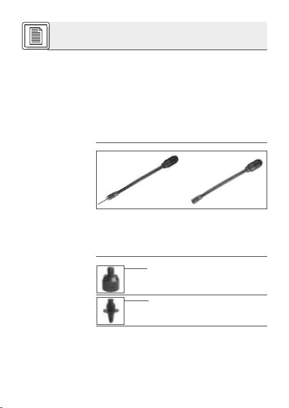
• Stativadapter SA 50 für 3/8”- und
5/8”-Gewinde mit Kabelauslass
• Montagesockel PS 3 F-Lock mit
3-poliger XLR-Buchse und
Diebstahlsicherung
• Dynamisches Schwanenhalsmikrofon mit robustem Ganzmetallgehäuse.
• Hohe Rückkopplungssicherheit durch nierenförmige Richtcharakteristik.
•Frequenzgang auf Sprachübertragung abgestimmt.
Page 3
1 Beschreibung
•Mattgraue, nicht lichtreflektierende Oberfläche.
• Einfache Montage.
Das D 542/D 542 E ist ein dynamisches Mikrofon
mit 22 cm langem Schwanenhals für folgende
Anwendungsbereiche: Schausteller, Jahrmarktbuden, Imbissstände, Schnellrestaurants,
Portierlogen, Hotelrufanlagen, Konferenzanlagen,
Sakralräume (z.B. Kanzel), auf Mischpulten im
Tonstudio oder auf der Bühne, in Autobussen,
Zügen, usw.
Die nierenförmige Richtcharakteristik garantiert
geringe Anfälligkeit für Störgeräusche aus der
Umgebung und Rückkopplungen. Der Frequenzgang des Mikrofons ist speziell auf Sprachübertragung ausgelegt.
Das robuste Ganzmetallgehäuse ist mattgrau
lackiert und verursacht daher keine Lichtreflexe.
Das D 542 ist mit einem 3 m langen, fix verbunde-
nen Kabel mit freien Enden ausgestattet und eignet sich zur Befestigung auf Tischplatten oder
(mittels optionalem Stativadapter SA 50) auf Mikrofonstativen mit 3/8”- oder 5/8”-Gewinde.
Das D 542 E besitzt einen 3-poligen XLR-Stecker
zum direkten Anschluss an XLR-Buchsen, z.B.
den Talkback-Eingang eines Mischpults.
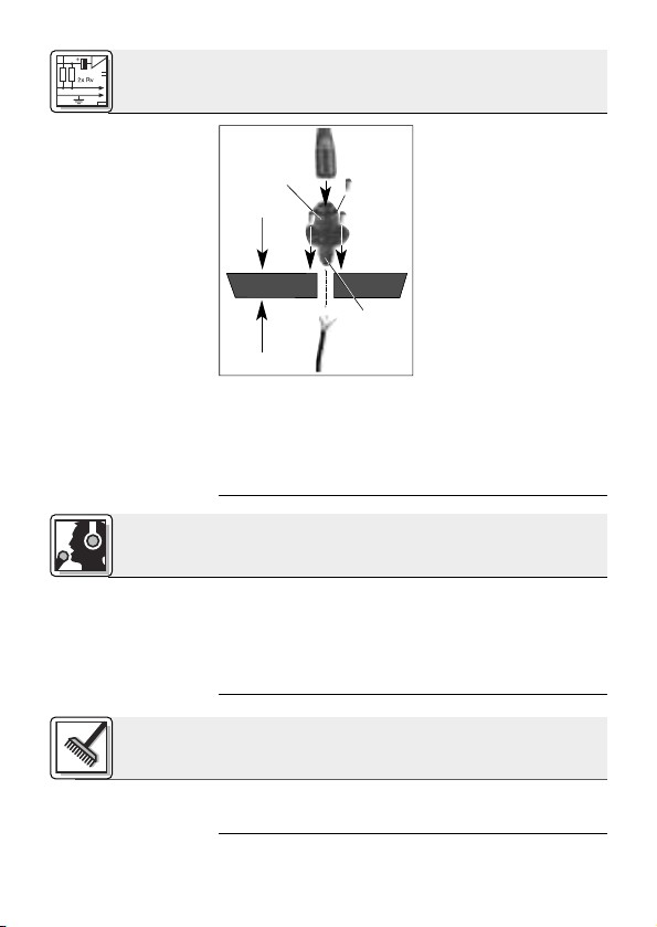
2 Montage und Anschluss
Sie können das D 542 in jede Holz-, Metall- oder
Kunststoffplatte mit einer maximalen Stärke von
19 mm einbauen.
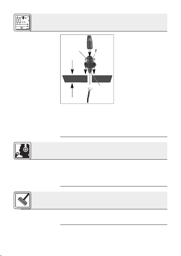
1. Schrauben Sie die Befestigungsschraube (2) aus
dem Schwanenhals (1) heraus und ziehen Sie die
Befestigungsschraube (2) vom Kabel (3) ab.
1.6
Beschreibung
D 542
D 542 E
2.1 D 542
2.1.1 Montage in
einem Pult
Siehe Abb. 1.
3
Page 4
2 Montage und Anschluss
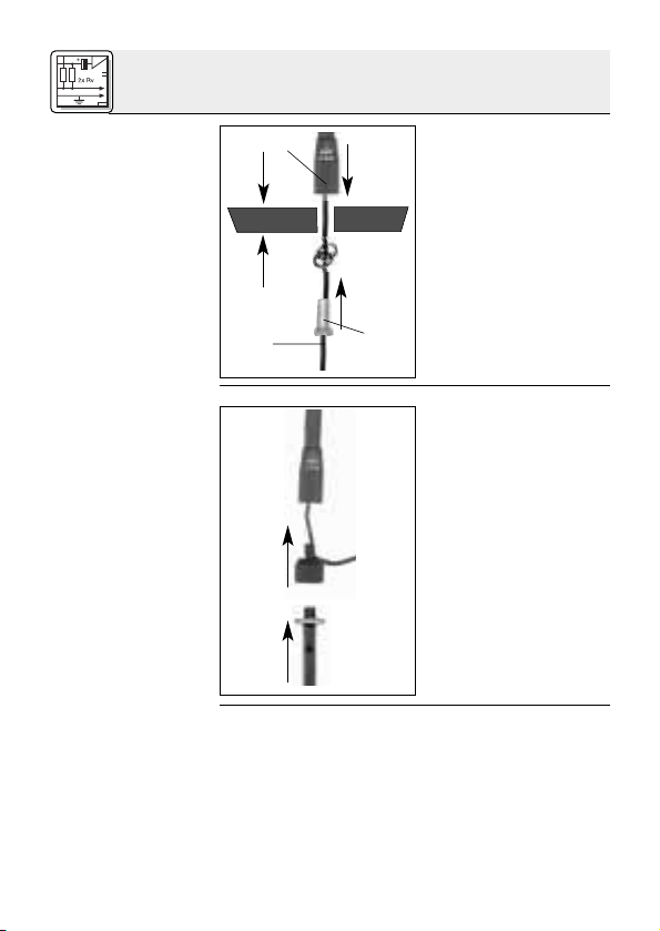
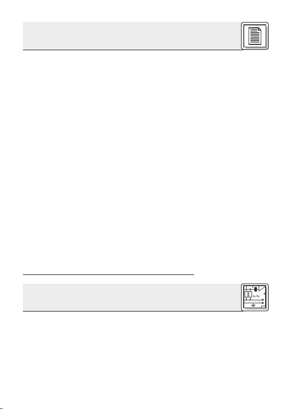
Abb. 1: Einbau in
eine Holz-, Metall-
oder Kunststoff-
platte
2.1.2 Montage an
einem
Mikrofonstativ
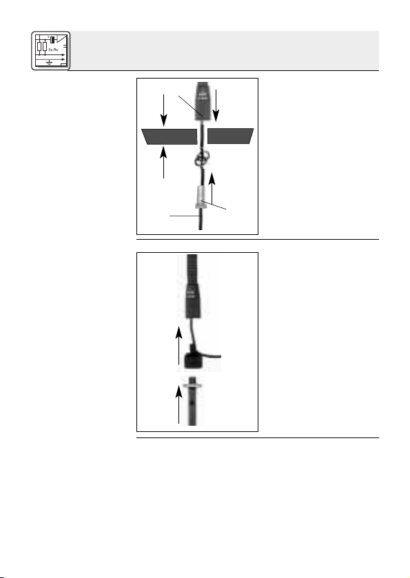
Abb. 2: Montage
an Mikrofonstativ
mit SA 50
2.1.3 Anschluss
Siehe Abb. 3.
4
19 mm max.
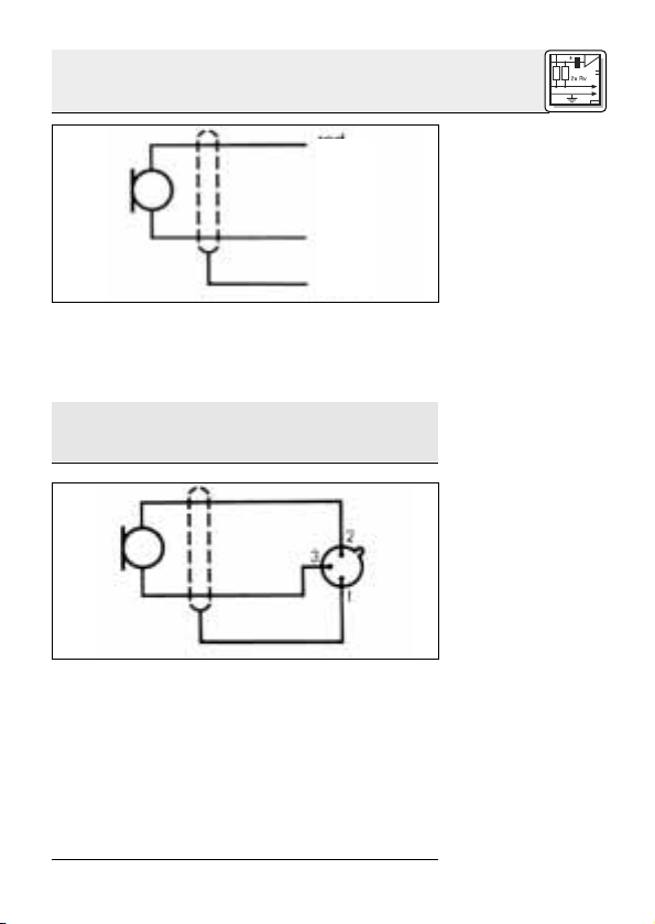
Das D 542 besitzt ein 3 m langes Anschlusskabel
mit offenen Enden:
Abschirmung (1) = Masse
rot (2) = Audio (inphase)
weiß (3) = Audio
Sie können das Mikrofon sowohl an symmetrische
als auch asymmetrische Mikrofoneingänge
anschließen.
2. Bohren Sie ein
Loch mit 12 mm
Durchmesser in die
Platte.
3. Befestigen Sie das
Mikrofon wie in
Abb. 1 dargestellt.
Mit dem optionalen
Stativadapter SA 50
können Sie das D 542
an jedem Mikrofonstativ mit 3/8”- oder 5/8”Gewinde montieren.
Page 5
2 Montage und Anschluss
2
3
1
Hinweise zum Anschluss des Kabels entnehmen
Sie bitte der Bedienungsanleitung des Gerätes, an
welches Sie das Mikrofon anschließen möchten.
Zum Anschluss an einen asymmetrischen Eingang müssen Sie die Abschirmung mit der weißen
Ader verbinden.
Das Mikrofon besitzt einen symmetrischen Ausgang mit 3-poligem XLR-Stecker:
Stift 1 = Masse
Stift 2 = Audio (inphase)
Stift 3 = Audio
Stecken Sie das Mikrofon an die Talkback-Buchse
des Mischpults an.
Abb. 3: Schaltdiagramm des
D 542
Hinweis:
2.2 D 542 E
Abb. 4: Schaltdiagramm des
D 542 E
Siehe Abb. 4.
5
Page 6
2 Montage und Anschluss
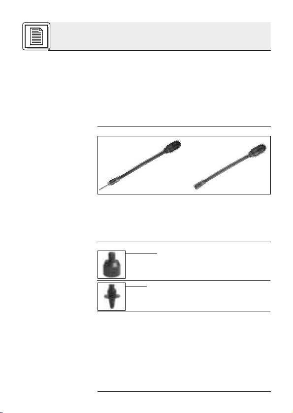
2.2.1 Einbau in
eine Tischplatte
Kontaktbelegung
siehe Abb. 4.
Abb. 5: Einbau mit-
tels PS 3 F-Lock
(optional)
3 Anwendung
4 Reinigung
1. Bohren Sie ein Loch
mit 17 mm Durch-
19 mm max.
befestigen Sie den Montagesockel mit den
beiliegenden Schrauben.
4. Stecken Sie das Mikrofon an die XLR-Buchse
an.
5. Ziehen Sie die Sicherungsschraube (2) an.
Um Störgeräusche aus der Umgebung zu überdecken und optimale Sprachverständlichkeit zu
erreichen, empfehlen wir, aus einer Entfernung
von ca. 10 cm von vorne in das Mikrofon zu sprechen.
messer in die Platte.
2. Schrauben Sie die
Tülle (1) ab und löten
Sie ein 2-poliges geschirmtes Kabel an
die XLR-Buchse an.
Schrauben Sie die
Tülle (1) wieder auf.
3. Fädeln Sie das Kabel durch die Montageöffnung und
Reinigen Sie die Gehäuseoberfläche des Mikrofons mit (Industrie-)Spiritus oder Alkohol.
6
Page 7
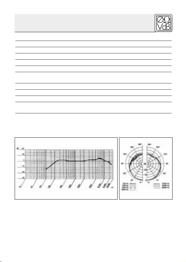
6 Technische Daten
Arbeitsweise: dynamisches Druckgradientenmikrofon
Richtcharakteristik: nierenförmig
Übertragungsbereich: 150 bis 15.000 Hz
Empfindlichkeit bei 1000 Hz: 2,2 mV/Pa (-53 dBV bez. auf 1 V/Pa)
Elektrische Impedanz bei 1000 Hz: ≤530 Ω
Empfohlene Lastimpedanz: ≥2000 Ω
Anschluss: D 542: fixes Kabel, 3 m, ohne Stecker
Gehäusematerial: Druckguss
Oberfläche: mattgrau lackiert
Abmessungen: L: 345 mm; max. ø: 35 mm
Gewicht (netto/brutto): D 542: 275 g / 422 g
Dieses Produkt entspricht der Norm EN 50 082-1
Frequenzgang Polardiagramm
D 542 E: 3-poliger Standard XLR-Stecker
D 542 E: 285 g / 334 g
7
Page 8
1 Precautions/Description
1.1 Precautions
1.2 Unpacking
1.3 Optional
Accessories for
the D 542
1.4 Optional
Accessories for
the D 542 E
1.5 Features
8
1. Please make sure that the piece of equipment
your microphone will be connected to fulfills
the safety regulations in force in your country
and is fitted with a ground lead.
2. Use the microphone for the applications described in this manual only. AKG cannot accept any liability for damages resulting from
improper handling or misuse.
1 D 542/D 542 E
Check that the package contains all the parts listed above. If anything is missing, please contact
your AKG dealer.
• SA 50 stand adapter with cable
leadout channel for 3/8" and 5/8"
threads.
• PS 3 F-Lock 3-socket female XLR
panel mount connector with
anti-theft lock.
• Dynamic gooseneck microphone with rugged
all-metal housing.
• Cardioid polar pattern for high gain before
feedback.
•Frequency response tailored to speech reproduction.
• Matte gray, non-reflective finish.
• Easy to install.
Page 9
1 Description
The D 542/D 542 E is a dynamic microphone with
a 9-inch (22-cm) gooseneck for the following application areas: fair grounds and amusement
parks, cafeterias, quick-lunch restaurants, ticket
windows, paging systems, convention centers,
places of worship, recording or sound reinforcement mixing consoles, busses, trains, etc.
The microphone's cardioid polar pattern ensures
good rejection of unwanted ambient noise and
provides high gain before feedback. The frequency response has been designed specifically
for speech reproduction. The all-metal housing is
finished in matte gray enamel and will cause no
light reflections.
The D 542 is fitted with a 10-ft. (3-m) fixed cable
with stripped-and-tinned leads. You can permanently install the microphone in a desktop or use
an optional SA 50 stand adapter to mount it temporarily on any microphone stand with a 3/8" or
5/8" thread.
The D 542 E features a 3-pin XLR connector for di-
rect connection to an XLR socket, such as the tailback input on a mixing console.
2 Installation and Connection
You can install the D 542 in any sheet of wood,
metal, or plastic with a maximum thickness of
0.7 in. (19 mm).
1. Unscrew the fixing screw (2) from the gooseneck (1) and remove the fixing screw (2) from
the cable (3).
2. Drill a 1/2" (12-mm) hole in the desktop.
1.6 Description
D 542
D 542 E
2.1 D 542
2.1.1 Desktop Installation
Refer to fig. 1.
9
Page 10
2 Installation and Connection
Fig. 1: Installing
the microphone in
a wood, metal, or
plastic desktop.
2.1.2 Stand
Mounting
Fig. 2: Using the
SA 50 to mount the
microphone on a
stand.
2.1.3 Connection
Refer to fig. 3.
19 mm max.
The D 542 is equipped with a 10-ft. (3-m) connecting cable with stripped-and-tinned leads:
Shield (1) = ground
Red (2) = audio inphase
White (3) = audio return
You can connect the microphone either to a
balanced or an unbalanced microphone input.
3. Install the microphone as shown in
fig. 1.
The optional SA 50
stand adapter lets you
mount the D 542 E on
any microphone stand
with a 3/8" or 5/8"
thread.
10
Page 11

2 Installation and Connection
2
3
1
For details on how to connect the cable please refer to the instruction manual of the equipment to
which you intend to connect your microphone.
Fig. 3: D 542 circuit
diagram.
To connect the microphone to an unbalanced
input, bridge the shield of the cable and the white
wire.
The microphone has a balanced output with a 3pin XLR connector:
Pin 1 - ground
Pin 2 - audio inphase
Pin 3 - audio return
Connect the microphone to the talkback input on
your mixing console.
Note:
2.2 D 542 E
Fig. 4: D 542 E
circuit diagram.
Refer to fig. 4.
11
Page 12
2 Installation and Connection
2.2.1 Desktop
Installation
Refer to fig. 4 for
connector pinout.
Fig. 5: Using the
optional PS 3 F-
Lock to install the
microphone.
3 Use
4 Cleaning
1. Drill a 11/16"
(17-mm) hole in the
19 mm max.
place using the screws supplied with the
PS 3 F-Lock.
4. Connect the microphone to the XLR connector
on the PS 3 F-Lock.
5. Tighten the securing screw (2).
To mask unwanted ambient noise and obtain
optimum intelligibility, we recommend talking into
the front grill of the microphone from a distance of
about 4 inches (10 cm).
desktop.
2. Unscrew the shell
(1) and solder a twoconductor shielded
cable to the XLR
connector. Replace
the shell (1).
3. Thread the cable
through the installation hole and fix the
PS 3 F-Lock in
12
Clean the surface of the microphone body with
(methylated) spirits or alcohol.
Page 13

6 Specifications
Type: dynamic pressure gradient microphone
Polar pattern: cardioid
Frequency range: 150 to 15,000 Hz
Sensitivity at 1000 Hz: 2.2 mV/Pa (–53 dBV re 1 V/Pa)
Electrical impedance at 1000 Hz: ≤530 Ω
Recommended load impedance: ≥2000 Ω
Connector: D 542: fixed cable (3 m/10 ft.) w/stripped-
Case material: die-cast metal
Finish: matte gray enamel
Size: length: 345 mm (13.6 in.);
Net/shipping weight: D 542: 275 g (9.7 0z.) / 422 g (15 oz.)
This product conforms to EN 50 082-1.
Frequency Response Polar Diagram
and-tinned leads
D 542 E: 3-pin XLR
max. dia.: 35 mm (1.4 in.)
D 542 E: 285 g (10.1 oz.) / 334 g (11.8 oz.)
13
Page 14

1 Consignes de sécurité / Description
1.1 Consignes
de sécurité
1.2 Fournitures
1.3 Accessoires
recommandés
pour D 542
1.4 Accessoires
recommandés
pour D 542 E
1. Vérifiez si l’appareil auquel vous voulez raccorder le microphone répond aux prescriptions relatives à la sécurité en vigueur et s’il possède
une mise à la terre de sécurité.
2. N’utilisez jamais le micro pour une application
autre que celles indiquées dans le mode d’emploi. AKG décline toute responsabilité concernant les dégâts qui résulteraient d’une manipulation inappropriée ou d’une utilisation non
conforme.
1 D 542/D 542 E
Assurez-vous que l’emballage contient bien toutes les pièces indiquées ci-dessus. Si ce n’est pas
le cas, contactez immédiatement votre fournisseur AKG.
• Elément-raccord SA 50 pour pas de
3/8" et 5/8" avec sortie de câble
• Socle de montage PS 3 F-Lock avec
embase XLR 3 points et antivol
Caractéristiques
1.5
particulières
14
• Microphone col-de-cygne dynamique avec
boîtier métallique robuste.
• Remarquable insensibilité au larsen grâce à la
caractéristique cardioïde.
•Réponse en fréquence adaptée à la parole.
Page 15

1 Description
• Boîtier gris mat, surface non réfléchissante.
• Simplicité de montage.
Le D 542/D 542 E est un microphone dynamique
avec col-de-cygne de 22 cm de long, destiné aux
applications suivantes : saltimbanques, baraques
foraines, kiosques de restauration, restaurants rapides, loges de concierges, systèmes d’appel
dans les hôtels, installations de conférence, églises (chaire), tables de mixage dans les studios de
prise de son ou sur la scène, autobus, trains, etc.
Grâce à sa caractéristique cardioïde, ce micro est
peu sensible au bruit environnant et au larsen. Sa
réponse en fréquence est spécialement adaptée à
la parole. La surface grise mat du boîtier métallique robuste, élimine les reflets.
Le D 542 est équipé d’un câble fixe de 3 m de
long, à extrémité libre ; il peut se fixer à un plateau
de table ou (à l’aide de l’élément-raccord SA 50
optionnel) à un support de micro à pas de 3/8" ou
5/8".
Le D 542 E possède un connecteur XLR 3 points
permettant de le relier directement sur une embase XLR, p.ex. entrée Talkback d’une table de
mixage.
2 Montage et raccordement
Vous pouvez monter le D 542 sur n’importe quel
panneau de bois, de métal ou de plastique d’une
épaisseur maximale de 19 mm.
1. Dévissez la vis de fixation (2) du col-de-cygne
(1) et détachez la vis de fixation (2) du câble (3).
2. Percez dans le panneau un trou de 12 mm de
diamètre.
1.6 Description
D 542
D 542 E
2.1 D 542
2.1.1 Montage sur
pupitre
Voir Fig. 1.
15
Page 16

2 Montage et raccordement
Fig. 1 : Montage
sur un panneau de
bois, de métal ou
de plastique
2.1.1 Montage
sur un pied de
micro
Fig. 2 : Montage
sur pied de micro à
l’aide du raccord
SA 50
2.1.3
Raccordement
Voir Fig. 3.
16
19 mm max.
Le D 542 possède un câble de raccordement de
3 m de long à extrémité libre.
blindage (1) = masse
rouge (2) = audio (point chaud)
blanc (3) = audio
Vous pouvez raccorder le micro au choix sur une
entrée micro symétrique ou asymétrique.
3. Fixez le micro
comme indiqué à
la Fig. 1.
A l’aide de l’élémentraccord optionnel
SA 50 vous pouvez
monter le D 542 sur
n’importe quel pied de
micro présentant un
pas de 3/8" ou 5/8".
Page 17

2 Montage et raccordement
2
3
1
Pour le raccordement du câble, veuillez vous reporter au mode d’emploi de l’appareil sur lequel
vous souhaitez connecter le micro.
Pour raccorder le micro à une entrée asymétrique,
reliez le blindage au fil blanc.
Le micro possède une sortie symétrique avec
connecteur XLR 3 points :
broche 1 = masse
broche 2 = audio (point chaud)
broche 3 = audio
Connectez le micro sur l’embase Talkback de la
table de mixage.
Fig. 3 : Schéma de
connexion du
D 542
Remarque :
2.2 D 542 E
Fig. 4 : Schéma de
connexion du
D 542 E
Voir Fig. 4.
17
Page 18

2 Montage et raccordement
2.2.1 Montage
sur un plateau de
table
Brochage
voir Fig. 4.
Fig. 5 : Montage à
l’aide du socle PS
3 F-Lock
(optionnel)
3 Utilisation
4 Nettoyage
1. Percez un trou de
17 mm de diamètre
19 mm max.
des trois vis fournies.
4. Connectez le micro sur l’embase XLR.
5. Serrez la vis de sécurité (2).
Pour couvrir le bruit ambiant et obtenir une netteté
optimale de la parole, il est conseillé de parler en
face du micro, la distance aux lèvres devant être
de 10 cm environ.
Le boîtier du micro se nettoie à l’alcool à brûler ou
à l’alcool.
dans le panneau.
2. Dévissez la douille
(1) et soudez un
câble blindé bipolaire à l’embase
XLR. Revissez la
douille (1).
3. Enfilez le câble dans
le trou que vous
avez percé et fixez
le socle au moyen
18
Page 19

6 Caractéristiques techniques
Fonctionnement:
Directivité: cardioïde
Gamme de fréquences: 150 à 15.000 Hz
Sensibilité à 1.000 Hz: 2,2 mV/Pa (-53 dBV rapporté à 1 V/Pa)
Impédance électrique à 1000 Hz: ≤530 Ω
Impédance de charge recommandée: ≥2000 Ω
Connexion: D 542: câble fixe de 3 m, sans connecteur
Matériau du boîtier: métal coulé sous pression
Surface: laquée mate, grise
Dimensions: L: 345 mm; max. Ø 35 mm
Poids (net/brut): D 542: 275 g / 422 g
microphone dynamique à gradient de pression
D 542 E: connecteur tripolaire XLR
D 542 E: 285 g / 334 g
Cet article répond à la norme EN 50 082-1
Réponse en fréquence Diagramme polaire
19
Page 20

1 Avvertenze di sicurezza / Descrizione
1.1 Avvertenze
di sicurezza
1.2 In dotazione
1.3 Accessori
raccomandati
per il D 542
1.4 Accessori
raccomandati
per il D 542 E
Caratteristiche
particolari
20
1. Controllate per favore se l’apparecchio che volete collegare al microfono corrisponde alle
norme di sicurezza vigenti e se è dotato di una
messa a terra di sicurezza.
2. Usate il microfono solo per gli impieghi descritti nelle presenti istruzioni per l’uso. La AKG
non assume nessuna responsabilità per danni
causati da manipolazione non effettuata a regola d’arte o da uso non corretto.
1 D 542/D 542 E
Controllate per favore se la confezione contiene
tutti i componenti di cui sopra. Se manca qualcosa rivolgetevi al vostro rivenditore AKG.
• Adattatore per supporto SA 50 per
• Zoccolo di montaggio PS 3 F-Lock
1.5
• Microfono dinamico a collo di cigno con robusta scatola interamente in metallo.
• Grande sicurezza contro il feedback, grazie
alla caratteristica cardioide.
• Risposta in frequenza sintonizzata sulla trasmissione della lingua parlata.
• Superficie grigio-opaca che non riflette la luce.
filetti da 3/8" e da 5/8" con
uscita per cavo
con presa XLR a tre poli e antifurto
Page 21

• Montaggio semplice.
1 Descrizione
Il D 542/D 542 E è un microfono dinamico con un
collo di cigno lungo 22 cm, adatto per i seguenti
impieghi: esposizioni, fiere, tavole calde, ristoranti
self-service, portinerie, impianti di chiamata in alberghi, impianti congressuali, vani sacrali (p.e.
pulpiti), mixer in studi fonici o sul palco, pullman,
treni ecc. La caratteristica cardioide garantisce
poca sensibilità nei confronti di rumori disturbanti
provenienti dall’ambiente o da feedback. La risposta in frequenza del microfono è predisposta
specialmente per la trasmissione della lingua parlata.
La robusta scatola interamente in metallo è verniciata in grigio-opaco e non causa quindi riflessi di
luce.
Il D 542 è dotato di un cavo lungo 3 m, collegato in
modo fisso, dalle estremità libere, e può essere
fissato sul piano di un tavolo o (con l’opzionale
adattatore per supporto SA 50) su supporti microfonici con filetti da 3/8" oppure 5/8".
Il D 542 E è dotato di un connettore XLR a tre poli
per il collegamento diretto a prese XLR, p.e. l’ingresso talkback di un mixer.
2 Montaggio e collegamento
Potete montare il D 542 su qualsiasi ripiano di
legno, metallo o materia sintetica con uno spessore massimo di 19 mm.
1.6 Descrizione
D 542
D 542 E
2.1 D 542
2.1.1 Montaggio
su ripiani
1. Svitate la vite di fissaggio (2) dal collo di cigno
(1) e sfilate la vite di fissaggio (2) dal cavo (3).
Vedi fig. 1.
21
Page 22

2 Montaggio e collegamento
Fig. 1: Montaggio
su un ripiano di
legno, metallo o
materia sintetica
2.1.2 Montaggio
su supporto
microfonico
Fig. 2: Montaggio
su supporto micro-
fonico con SA 50
2.1.3
Collegamento
Vedi fig. 3.
19 mm max.
Il D 542 è dotato di un cavo di collegamento lungo
3 m dalle estremità libere:
schermatura (1) = massa
rosso (2) = audio (inphase)
bianco (3) = audio
Potete collegare il microfono sia ad ingressi
microfonici simmetrici che asimmetrici.
2. Fate un foro (diametro 12 mm) nel
ripiano.
3. Fissate il microfono come indicato
nella fig. 1.
Con l’aiuto dell’opzionale adattatore per
supporto SA 50 potete
montare il D 542 su
ogni supporto microfonico con filetto da 3/8"
oppure 5/8".
22
Page 23

2 Montaggio e collegamento
2
3
1
Le avvertenze relative al collegamento del cavo
sono contenute nelle istruzioni per l’uso dell’apparecchio al quale volete collegare il microfono.
Fig. 3: Schema
elettrico del D 542
Per il collegamento ad un ingresso asimmetrico
dovete collegare la schermatura del cavo al filo
bianco.
Il microfono è dotato di un’uscita simmetrica con
connettore XLR a tre poli:
pin 1 = massa
pin 2 = audio (inphase)
pin 3 = audio
Inserite il microfono nella presa talkback del mixer.
Avvertenza:
2.2 D 542 E
Fig. 4: Schema
elettrico del
D 542 E
Vedi fig. 4.
23
Page 24

2 Montaggio e collegamento
2.2.1 Montaggio
sul ripiano di un
tavolo
Cablaggio contatti
vedi fig. 4.
Fig. 5: Montaggio
con l’aiuto di un
PS 3 F-Lock
(opzionale)
3 Impiego
4 Pulizia
1. Fate un foro (diame-
tro 17 mm) nel ripi-
19 mm max.
zoccolo di montaggio con le viti in dotazione.
4. Inserite il microfono nella presa XLR.
5. Serrate la vite di sicurezza (2).
Per sopprimere rumori ambientali disturbanti ed
ottenere ottimale intelligibilità della parola, raccomandiamo di parlare nel microfono dal davanti, ad
una distanza di circa 10 cm.
Pulite la superficie del corpo del microfono con
spirito (industriale) o alcol.
ano.
2. Svitate la bossola
(1) e fissate, mediante saldatura, un
cavo schermato a 2
poli alla presa XLR.
Riavvitate la bossola (1).
3. Infilate il cavo attra-
verso il foro di montaggio e fissate lo
24
Page 25

6 Dati tecnici
Modo di funzionamento: microfono dinamico a gradiente di pressione
Direttività: cardioide
Risposta in frequenza: da 150 fino a 15.000 Hz
Sensibilità a 1000 Hz: 2,2 mV/Pa (=-53 dBV rif. a 1V/Pa)
Impedenza elettrica a 1000 Hz: ≤530 Ω
Impedenza di carico raccomandata:≥2000 Ω
Tipo di connettore: D 542: cavo fisso da 3 m, senza connettore
Materiale della scatola: pressofuso
Superficie: verniciata in grigio opaco
Dimensioni: lunghezza 345 mm, diametro mass.: 35 mm
Peso (netto/lordo): D 542: 275 g / 422 g
Questo prodotto corrisponde alla norma EN 50 082-1
Risposta in frequenza Diagramma polare
D 542 E: connettore XLR standard a 3 poli
D 542 E: 285 g / 334 g
25
Page 26

1
Indicaciones de seguridad / Descripción
1.1 Indicaciones
de seguridad
1.2 Volumen de
suministro
1.3 Accesorios
recomendados
para el D 542
1.4 Accesorios
recomendados
para el D 542 E
1.5
Características
especiales
26
1. Sírvase verificar si el aparato al cual quiere
conectar el micrófono cumple con las disposiciones de seguridad vigentes y está equipado
con una toma de tierra de seguridad.
2. El micrófono debe ser utilizado sólo para los fines descriptos en estas instrucciones de uso.
AKG no se responsabiliza por daños debidos a
un uso inadecuado o indebido.
1 D 542/D 542 E
Sírvase controlar si el embalaje contiene todas las
piezas indicadas arriba. Si falta algo, le rogamos
dirigirse a su distribuidor AKG.
• Adaptador de soporte SA 50 para
roscas de 3/8" y 5/8" con
salida de cable
• Zócalo de montaje PS 3 F-Lock con
conector hembra XLR de 3 pines y
seguro contra robo
• Micrófono dinámico con brazo flexible y robusta caja metálica.
• Alta seguridad contra la retroalimentación debido a la característica direccional cardioide.
• Respuesta de frecuencia adaptada a la transmisión del habla.
• Superficie gris mate que no refleja la luz.
• Simple montaje.
Page 27

1
Descripción
El D 542/D 542 E es un micrófono dinámico con
brazo flexible de 22 cm de longitud diseñado para
los siguientes usos: expositores, puestos de feria,
merenderos, establecimientos de comida rápida,
porterías, instalaciones de llamadas para hoteles,
instalaciones para salas de conferencias, recintos
sagrados (ej.: púlpito), mesas de mezclas de estudios de grabación o escenarios, autobuses, trenes, etc.
La característica direccional cardioide garantiza
una baja sensibilidad al ruido del medioambiente
y a la retroalimentación. La respuesta de frecuencia del micrófono está especialmente diseñada
para la transmisión del habla.
Su robusta caja metálica laqueada de color gris
mate no produce reflejos luminosos.
El D 542 posee un cable fijo de 3 metros de longi-
tud con extremos libres y es apto para ser fijado a
tableros de mesa o a soportes de micrófono con
rosca de 3/8" o 5/8" (utilizando el adaptador de
soporte SA 50 opcional).
El D 542 E tiene un conector macho XLR de 3 pi-
nes para la conexión directa a conectores hembra
XLR (ej.: la entrada de Talkback de una mesa de
mezclas).
2 Montaje y conexión
El D 542 puede ser montado a cualquier tabla de
madera, metal o plástico con un espesor máximo
de 19 mm. Pasos a seguir:
1. Desenrosque el tornillo de fijación (2) del cuello
flexible (1) y saque el tornillo de fijación (2) del
cable (3).
2. Taladre en la tabla un agujero de 12 mm de diámetro.
1.6 Descripción
D 542
D 542 E
2.1 D 542
2.1.1 Montaje en
un pupitre
Ver dib. 1.
27
Page 28

2 Montaje y conexión
Dib. 1: Montaje en
una tabla de ma-
dera, metal o
plástico
2.1.2 Montaje en
un soporte de
micrófono
Dib. 2: Montaje en
un soporte de
micrófono uti-
lizando el SA 50
2.1.3 Conexión
Ver dib. 3.
28
19 mm max.
El D 542 posee un cable de conexión de tres metros de longitud con extremos abiertos:
blindaje (1) = masa
rojo (2) = audio (inphase)
blanco (3) = audio
El micrófono puede ser conectado tanto a entradas balanceadas como a entradas no balanceadas.
3. Fije el micrófono
como se indica en
el dib. 1.
Utilizando el adaptador
de soporte SA 50 opcional puede montar el
D 542 a cualquier soporte de micrófono con
rosca de 3/8" o 5/8".
Page 29

2 Montaje y conexión
2
3
1
Para la conexión del cable se deben seguir las indicaciones del manual de instrucciones de uso
del aparato al que se conectará el micrófono.
Dib. 3: Esquema
eléctrico del D 542
Para conectar el micrófono a una entrada no balanceada debe conectar el blindaje con el hilo
conductor blanco.
El micrófono posee una salida balanceada con
conector macho XLR de 3 pines:
contacto 1 = masa
contacto 2 = audio (inphase)
contacto 3 = audio
Enchufe el micrófono en la entrada Talkback de la
mesa de mezclas.
Nota:
2.2 D 542 E
Dib. 4: Esquema
eléctrico del D 542 E
Ver dib. 4.
29
Page 30

2 Montaje y conexión
2.2.1 Montaje en
un tablero de
mesa
Ocupación de los
contactos:
ver dib. 4.
Dib. 5: Montaje
con PS 3 F-Lock
(opcional)
3 Utilización
4 Limpieza
1. Taladre en la tabla
un agujero de 17
19 mm max.
zócalo de montaje utilizando los tornillos suministrados.
4. Enchufe el micrófono en el conector hembra
XLR.
5. Apriete el tornillo de retención (2).
Para que la voz tape los ruidos del medioambiente
y se entienda bien, le recomendamos que hable
colocando la boca delante del micrófono a unos
10 cm de distancia del mismo.
mm de diámetro.
2. Desenrosque la boquilla (1) y suelde un
cable blindado de 2
hilos al conector
hembra XLR. Vuelva
a enroscar la boquilla (1).
3. Pase el cable a través del orificio de
montaje y fije el
30
Limpie la superficie de la caja del micrófono con
alcohol industrial o normal.
Page 31

6 Datos técnicos
Funcionamiento: micrófono dinámico a gradiente de presión
Característica direccional: cardioide
Gama de frecuencia: 150 a 15.000 Hz
Sensibilidad a 1000 Hz: 2,2 mV/Pa (-53 dBV ref. a 1V/Pa)
Impedancia eléctrica a 1000 Hz: ≥530 Ω
Impedancia de carga recomendada: ≥2000 Ω
Conector: D 542: cable fijo de 3 m, sin conector
Material de la caja: colada a presión
Superficie: laqueada en gris opaco
Dimensiones: largo: 345 mm; diámetro máx.: 35 mm
Peso (neto/bruto): D 542: 275 g / 422 g
Este producto corresponde a la norma EN 50 082-1
Respuesta de frecuencia Diagrama polar
D 542 E: conector estándar XLR de 3 polos
D 542 E: 285 g / 334 g
31
Page 32

1 Avisos de segurança/Descrição
1.1 Precauções
1.2 Volume de
fornecimento
1.3 Acessórios
recomendados
para o D 542
1.4 Acessórios
recomendados
para o D 542 E
1.5
Características
especiais
1. Certifique-se de que o aparelho ao qual pretende ligar o microfone está ligado à terra e
que corresponde às normas de segurança.
2. Utilize este microfone exclusivamente para os
fins descritos neste manual. A AKG não se responsabiliza por danos provocados por uso impróprio ou operação errada.
1 D 542/D 542 E
Verifique se a embalagem contém todos os componentes acima indicados. Caso falte algo, favor
entre em contato com a concessionária da AKG.
• Adaptador de tripé SA 50 para roscas
de 3/8" e 5/8", com saída de cabo.
• Base de montagem PS 3 F-Lock
com entrada de 3 pólos XLR e
dispositivo anti-furto.
• Microfone dinâmico com pescoço de cisne e
carcaça de metal.
• Alta proteção contra realimentações através
da característica cardióide.
• Resposta de freqüência adaptada à transmissão de fala.
• Superfície parda mate não refletora.
• Montagem simples.
32
Page 33

1 Descrição
O D 542/D 542 E é um microfone dinâmico com
um pescoço de cisne de 22 cm para as seguintes
aplicações: feirantes, quermesse, barracas de comida, lanchonetes, portarias, instalações de chamada em hotéis, instalações de conferência, centros de culto religioso (por exemplo para o uso em
púlpitos), em mesas de mixagem no estúdio ou no
palco, em ônibus, trens, etc.
A característica cardióide garante a baixa tolerância em relação a ruídos do ambiente e realimentações. A resposta de freqüência do microfone é
concebido especialmente para a transmissão de
fala.
A carcaça completamente de metal é pintada em
cor parda e mate evitando assim reflexões da luz.
O D 542 está provido dum cabo permanente-
mente ligado de 3 m de comprimento com fins livres e é apropriado para ser fixado numa tábua de
mesa ou (com o adaptador de tripé opcional
SA 50) em tripés de microfone com rosca de 3/8"
ou 5/8".
O D 542 E possui uma saída de 3 polos XLR para
ligar diretamente a entradas XLR, como por exemplo entradas talkback em mesas de mixagem.
2 Montagem e conexão
Pode fixar o D 542 em toda placa de madeira, metal ou plástico que possua uma espessura máxima de 19 mm.
1.6
Apresentação
em breve
D 542
D 542 E
2.1 D 542
2.1.1 Montagem
numa placa
1. Desenrosque o parafuso de fixação (2) do pescoço de cisne (1) e retire o parafuso de fixação
(2) do cabo (3).
Veja fig. 1.
33
Page 34

2 Montagem e conexão
Fig. 1: Montagem
numa placa de
madeira, metal ou
plástico
2.1.2 Montagem
num tripé de
microfone
Fig. 2: Montagem
num tripé de
microfone com o
SA 50
2.1.3 Conexão
Veja fig. 3.
19 mm máx.
O D 542 possui um cabo de conexão de 3 m de
comprimento com extremidades descascadas:
Pode ligar o microfone a entradas balanceadas ou
a entradas não balanceadas.
malha (1) = massa
vermelho (2) = áudio (positivo)
branco (3) = áudio (negativo)
2. Faça um buraco
com um diâmetro
de 12 mm na
placa.
3. Fixe o microfone
como demostra a
fig. 1.
Com o adaptador de
tripé opcional SA 50
pode montar o D 542
em qualquer tripé de
microfone com rosca
de 3/8" ou 5/8".
34
Page 35

2 Montagem e conexão
2
3
1
Para conectar o cabo leia as instruções do manual
do aparelho a que pretende ligar o microfone.
Fig. 3: Esquema
elétrico do D 542
Para a ligação a uma entrada não balanceada é
necessário ligar a malha do cabo ao fio branco.
O microfone possui uma saída balanceada XLR
com 3 polos:
pino 1 = massa
pino 2 = áudio (positivo)
pino 3 = áudio (negativo)
Ligue o microfone à entrada talkback da mesa de
mixagem.
Aviso:
2.2 D 542 E
Fig. 4: Esquema
elétrico do D 542 E
Veja fig. 4.
35
Page 36

2 Montagem e conexão
2.2.1 Montagem
numa placa de
mesa
Configuração do
conetor veja fig. 4.
Fig. 5: Montagem
através do
PS 3 F-Lock
(opcional)
3 Aplicação
4 Limpeza
1. Faça um buraco
com um diâmetro
19 mm max.
parafusos fornecidos na embalagem.
4. Ligue o microfone ao conetor XLR.
5. Aperte o parafuso de segurança (2).
Para disfarçar ruídos ambientais e para atingir a
melhor clareza da fala recomendamos falar do
lado da frente do microfone a uma distância de
aproximadamente 10 cm.
Limpe a superfície da carcaça do microfone com
álcool etílico (industrial) ou com álcool.
de 17 mm na placa.
2. Desenrosque a
capa (1) e solde um
cabo blindado de 2
núcleos no conetor
XLR. Recoloque a
capa (1).
3. Enfie o cabo pela
abertura de montagem e fixe a base de
montagem com os
36
Page 37

6 Especificações
Tipo: microfone dinâmico de gradiente de pressão
Característica direcional: cardióide
Região de freqüência: 150 a 15.000 Hz
Sensibilidade a 1000 Hz: 2,2 mV/Pa (-53 dBV em relação a 1V/Pa)
Impedância elétrica a 1000 Hz: ≤530 Ω
Impedância de carga recomendada: ≥2000 Ω
Tipo do conector: D 542: cabo permanentemente liado, sem
Material da carcaça: metal moldado sob pressão
Acabamento: tinta parda mate
Dimensões: comprimento: 345 mm
Peso (líquido/bruto): D 542: 275 g / 422 g
Este produto corresponde à norma EN 50 082-1.
Resposta de frequência Diagrama polar
conector
D 542 E: XLR standard de 3 pinos
diâmetro máx.: 35 mm
D 542 E: 285 g / 334 g
37
Page 38

Notizen - Notes - Notes - Note - Notas - Notas
38
Page 39

Notizen - Notes - Notes - Note - Notas - Notas
39
Page 40

AKG Acoustics GmbH
Lemböckgasse 21–25, P.O.B. 158, A-1230 Vienna/AUSTRIA, Tel: (43 1) 86 654-0*, Fax: (43 1) 86 654-7516,
http://www.akg.com, e-mail: sales@akg.com
AKG Acoustics GmbH
Bodenseestraße 228, D-81243 München/GERMANY, Tel: (089) 87 16-0, Fax: (089) 87 16-200,
http://www.akg-acoustics.de, e-mail: info@akg-acoustics.de
AKG ACOUSTICS, U.S.
914 Airpark Center Drive, Nashville, TN 37217, U.S.A., Tel: (615) 620-3800, Fax: (615) 620-3875,
http://www.akgusa.com, e-mail: akgusa@harman.com
For other products and distributors worldwide see our website: http://www.akg.com
Mikrofone · Kopfhörer · Drahtlosmikrofone · Drahtloskopfhörer · Kopfsprechgarnituren · Akustische Komponenten
Microphones · Headphones · Wireless Microphones · Wireless Headphones · Headsets · Electroacoustical Components
Microphones · Casques HiFi · Microphones sans fil · Casques sans fil · Micros-casques · Composants acoustiques
Microfoni · Cuffie HiFi · Microfoni senza filo · Cuffie senza filo · Cuffie-microfono · Componenti acustici
Micrófonos · Auriculares · Micrófonos inalámbricos · Auriculares inalámbricos · Auriculares con micrófono · Componentes acústicos
Microfones · Fones de ouvido · Microfones s/fios · Fones de ouvido s/fios · Microfones de cabeça · Componentes acústicos
Technische Änderungen vorbehalten. Specifications subject to change without notice. Ces caractéristiques sont susceptibles de modifications.
Ci riserviamo il diritto di effettuare modifiche tecniche. Nos reservamos el derecho de introducir modificaciones técnicas. Especificações sujeitas à mudanças sem aviso prévio.
Printed in Austria on recycled paper. 10/01/9100 U 0874
 Loading...