

Page 1
CS 2
Bedienungsanleitung. . . . . . . . . . . . S. 2
☞ Bitte vor Inbetriebnahme des Gerätes lesen!
User Instructions. . . . . . . . . . . . . . p. 12
☞ Please read the manual before using the equipment!
Mode d’emploi. . . . . . . . . . . . . . . . p. 22
☞ Veuillez lire cette notice avant d’utiliser le système!
Istruzioni per l’uso. . . . . . . . . . . . . p. 32
☞ Prima di utilizzare l’apparecchio, leggere il manuale
Modo de empleo . . . . . . . . . . . . . . p. 42
☞ ¡Sirvase leer el manual antes de utilizar el equipo!
Instruções de uso . . . . . . . . . . . . . p. 52
☞ Favor leia este manual antes de usar o equipamento!
Page 2

Inhaltsverzeichnis
1 Sicherheit und Umwelt . . . . . . . . . . . . . . . . . . . . . . . . . . . . . . . . . . . . . . . . . . . . . . . . . . . 2
1.1 Sicherheit. . . . . . . . . . . . . . . . . . . . . . . . . . . . . . . . . . . . . . . . . . . . . . . . . . . . . . . . . . 2
1.2 Umwelt. . . . . . . . . . . . . . . . . . . . . . . . . . . . . . . . . . . . . . . . . . . . . . . . . . . . . . . . . . . . 3
2 Beschreibung. . . . . . . . . . . . . . . . . . . . . . . . . . . . . . . . . . . . . . . . . . . . . . . . . . . . . . . . . . . 3
2.1 Einleitung . . . . . . . . . . . . . . . . . . . . . . . . . . . . . . . . . . . . . . . . . . . . . . . . . . . . . . . . . . 3
2.2 Lieferumfang . . . . . . . . . . . . . . . . . . . . . . . . . . . . . . . . . . . . . . . . . . . . . . . . . . . . . . . 3
2.3 Optionales Zubehör . . . . . . . . . . . . . . . . . . . . . . . . . . . . . . . . . . . . . . . . . . . . . . . . . . 3
2.4 Zentrale CS 2 BU . . . . . . . . . . . . . . . . . . . . . . . . . . . . . . . . . . . . . . . . . . . . . . . . . . . . 3
2.4.1 Frontplatte. . . . . . . . . . . . . . . . . . . . . . . . . . . . . . . . . . . . . . . . . . . . . . . . . . . . . 3
2.4.2 Rückseite . . . . . . . . . . . . . . . . . . . . . . . . . . . . . . . . . . . . . . . . . . . . . . . . . . . . . 4
2.5 Sprechstellen . . . . . . . . . . . . . . . . . . . . . . . . . . . . . . . . . . . . . . . . . . . . . . . . . . . . . . . 5
2.5.1 Oberseite. . . . . . . . . . . . . . . . . . . . . . . . . . . . . . . . . . . . . . . . . . . . . . . . . . . . . . 5
2.5.2 Unterseite . . . . . . . . . . . . . . . . . . . . . . . . . . . . . . . . . . . . . . . . . . . . . . . . . . . . . 5
Blockschaltbild . . . . . . . . . . . . . . . . . . . . . . . . . . . . . . . . . . . . . . . . . . . . . . . . . . . . . . . . 63
3 Inbetriebnahme . . . . . . . . . . . . . . . . . . . . . . . . . . . . . . . . . . . . . . . . . . . . . . . . . . . . . . . . . 5
3.1 Zentrale(n) . . . . . . . . . . . . . . . . . . . . . . . . . . . . . . . . . . . . . . . . . . . . . . . . . . . . . . . . . 5
3.1.1 Zentrale(n) konfigurieren . . . . . . . . . . . . . . . . . . . . . . . . . . . . . . . . . . . . . . . . . . 5
3.1.2 Kaskadieren mehrerer Zentralen . . . . . . . . . . . . . . . . . . . . . . . . . . . . . . . . . . . . 6
3.1.3 Fernschalt- und Anzeigeelemente anschließen. . . . . . . . . . . . . . . . . . . . . . . . . . 6
3.1.4 Equalizer oder Feedback-Killer anschließen . . . . . . . . . . . . . . . . . . . . . . . . . . . . 6
3.1.5 Andere externe Geräte anschließen . . . . . . . . . . . . . . . . . . . . . . . . . . . . . . . . . . 6
3.2 Sprechstellen . . . . . . . . . . . . . . . . . . . . . . . . . . . . . . . . . . . . . . . . . . . . . . . . . . . . . . . 6
3.2.1 Sprechstellen konfigurieren . . . . . . . . . . . . . . . . . . . . . . . . . . . . . . . . . . . . . . . . 6
3.2.2 Sprechstellen "CS 2 DU fix"/"CS 2 CU fix" einbauen . . . . . . . . . . . . . . . . . . . . . 7
3.2.3 Sprechstellen anschließen . . . . . . . . . . . . . . . . . . . . . . . . . . . . . . . . . . . . . . . . . 7
3.2.4 Mikrofone anschließen. . . . . . . . . . . . . . . . . . . . . . . . . . . . . . . . . . . . . . . . . . . . 8
3.3 Netzanschluss . . . . . . . . . . . . . . . . . . . . . . . . . . . . . . . . . . . . . . . . . . . . . . . . . . . . . . 8
4 Betriebshinweise . . . . . . . . . . . . . . . . . . . . . . . . . . . . . . . . . . . . . . . . . . . . . . . . . . . . . . . . 9
4.1 Einschalten. . . . . . . . . . . . . . . . . . . . . . . . . . . . . . . . . . . . . . . . . . . . . . . . . . . . . . . . . 9
4.2 Ausschalten . . . . . . . . . . . . . . . . . . . . . . . . . . . . . . . . . . . . . . . . . . . . . . . . . . . . . . . . 9
4.3 Teilnehmerbegrenzung einstellen . . . . . . . . . . . . . . . . . . . . . . . . . . . . . . . . . . . . . . . . 9
4.4 Mikrofone aktivieren und deaktivieren (Voice Activation und Automute). . . . . . . . . . . . 9
4.5 Lautsprecher einstellen. . . . . . . . . . . . . . . . . . . . . . . . . . . . . . . . . . . . . . . . . . . . . . . . 9
4.6 Voice Zoom einstellen . . . . . . . . . . . . . . . . . . . . . . . . . . . . . . . . . . . . . . . . . . . . . . . . 9
4.7 Hinweise zum Betrieb der Sprechstellen. . . . . . . . . . . . . . . . . . . . . . . . . . . . . . . . . . . 9
4.8 Interne Sicherungen der Zentrale austauschen . . . . . . . . . . . . . . . . . . . . . . . . . . . . . 10
Seite
5 Reinigung . . . . . . . . . . . . . . . . . . . . . . . . . . . . . . . . . . . . . . . . . . . . . . . . . . . . . . . . . . . . . 10
6 Fehlerbehebung . . . . . . . . . . . . . . . . . . . . . . . . . . . . . . . . . . . . . . . . . . . . . . . . . . . . . . . . 10
7 Technische Daten . . . . . . . . . . . . . . . . . . . . . . . . . . . . . . . . . . . . . . . . . . . . . . . . . . . . . . 11
7.1 Zentrale CS 2 BU . . . . . . . . . . . . . . . . . . . . . . . . . . . . . . . . . . . . . . . . . . . . . . . . . . . 11
7.2 Sprechstellen CS 2 DU / CS 2 CU . . . . . . . . . . . . . . . . . . . . . . . . . . . . . . . . . . . . . . 11
1 Sicherheit und Umwelt
1.1 Sicherheit
1. Schütten Sie keine Flüssigkeiten auf das Gerät und lassen Sie keine sonstigen Gegenstände durch
die Lüftungsschlitze in das Gerät fallen.
2. Das Gerät darf nur in trockenen Räumen eingesetzt werden.
3. Das Gerät darf nur von autorisiertem Fachpersonal geöffnet, gewartet und repariert werden. Im
Inneren des Gehäuses befinden sich keinerlei Teile, die vom Laien gewartet, repariert oder ausgetauscht werden können.
4. Prüfen Sie vor Inbetriebnahme des Gerätes, ob die auf dem mitgelieferten Netzgerät angegebene
Betriebsspannung der Netzspannung am Einsatzort entspricht.
5. Betreiben Sie das Gerät ausschließlich mit dem mitgelieferten Netzgerät CS PS 20 oder CS PS 100
mit einer Sekundärspannung von 23 bis 36 V DC. Andere Stromarten und Spannungen könnten das
Gerät ernsthaft beschädigen!
6. Brechen Sie den Betrieb der Anlage sofort ab, wenn ein fester Gegenstand oder Flüssigkeit in das
Geräteinnere gelangen sollte. Ziehen Sie in diesem Fall sofort das Netzkabel aus der Steckdose und
lassen Sie das Gerät von unserem Kundendienst überprüfen.
7. Ziehen Sie das Netzkabel bei längerer Nichtverwendung aus der Steckdose. Bitte beachten Sie, dass
bei angestecktem Netzgerät das Gerät nicht vollständig vom Netz getrennt wird, wenn Sie es ausschalten.
8. Stellen Sie das Gerät nicht in der Nähe von Wärmequellen wie z. B. Radiatoren, Heizungsrohren,
Verstärkern, usw. auf und setzen Sie es nicht direkter Sonneneinstrahlung, starker Staub- und
Feuchtigkeitseinwirkung, Regen, Vibrationen oder Schlägen aus.
9. Verlegen Sie zur Vermeidung von Störungen bzw. Einstreuungen sämtliche Leitungen, speziell die der
Mikrofoneingänge, getrennt von Starkstromleitungen und Netzleitungen. Bei Verlegung in Schächten
oder Kabelkanälen achten Sie darauf, die Übertragungsleitungen in einem separaten Kanal unterzubringen.
2
Page 3

1 Sicherheit und Umwelt
10.Reinigen Sie das Gerät nur mit einem feuchten, aber nicht nassen Tuch. Ziehen Sie unbedingt das
Netzkabel vorher aus der Steckdose! Verwenden Sie keinesfalls scharfe oder scheuernde
Reinigungsmittel sowie keine, die Alkohol oder Lösungsmittel enthalten, da diese den Lack sowie die
Kunststoffteile beschädigen könnten.
1. Das Netzgerät CS PS 20 nimmt auch bei ausgeschaltetem Gerät Strom auf. Um Energie zu sparen, ziehen Sie daher das Netzkabel von der Netzsteckdose ab, wenn Sie das Gerät längere Zeit nicht benützen.
2. Wenn Sie das Gerät verschrotten, trennen Sie Gehäuse, Elektronik und Kabel und entsorgen Sie alle
Komponenten gemäß den dafür geltenden Entsorgungsvorschriften.
2 Beschreibung
Vielen Dank, dass Sie sich für ein Produkt aus dem Hause AKG entschieden haben. Bitte lesen Sie die
Bedienungsanleitung aufmerksam durch, bevor Sie das Gerät benützen, und bewahren Sie die
Bedienungsanleitung sorgfältig auf, damit Sie jederzeit nachschlagen können. Wir wünschen Ihnen viel
Erfolg!
Das Konferenzsystem CS 2 von AKG bietet hervorragende Audioqualität und ist dank Einkabeltechnik
rasch und einfach zu installieren. Durch den modularen Aufbau können Sie das System mühelos an die
Anforderungen Ihrer Kunden anpassen. Es stehen Ihnen dazu verschiedene Verbindungskabel,
Sprechstellen für Tischaufbau oder fixe Montage im Tisch, Netzgeräte, Schwanenhälse und
Mikrofonkapseln zur Verfügung.
Die Zentrale CS 2 BU versorgt und steuert bis zu 200 Sprechstellen. Für Anlagen mit maximal
40 Sprechstellen benötigen Sie ein Netzgerät CS PS 20, für Anlagen mit bis zu 200 Sprechstellen ein
Netzgerät CS PS 100.
Sowohl die Vorsitzendensprechstelle CS 2 CU mit Vorrangtaste als auch die Delegiertensprechstelle
CS 2 DU ist mit einem patentierten verschraubbaren Anschluss für einen Schwanenhals GN 30 CS
(30 cm) oder GN 50 CS (50 cm) ausgestattet. An den Schwanenhals können Sie eine von 5 verschiedenen Mikrofonkapseln der Discreet Acoustics Serie von AKG anschließen.
Kontrollieren Sie bitte, ob die Lieferung jede der folgenden 7 Komponenten in der von Ihnen bestellten
Menge enthält. Sollte dies nicht der Fall sein, wenden Sie sich bitte an Ihre AKG-Vertretung.
1.2 Umwelt
2.1 Einleitung
2.2 Lieferumfang
1. Zentrale CS 2 BU
2. Netzgerät: CS PS 20 oder CS PS 100
3. Netzkabel: CS MK AC-EU, CS MK AC-US oder CS MK AC-UK
4. Sprechstellen: CS 2 DU, CS 2 DU fix, CS 2 CU oder CS 2 CU fix
5. Verbindungskabel: CS MK 1.25 fm, CS MK 2.5 fm, CS MK 5 fm, CS MK 10 fm oder CS MK 20 fm
6. Schwanenhälse: GN 30 CS oder GN 50 CS
7. Mikrofonkapseln: CK 31, CK 32, CK 33, CK 80 oder CK 47
Eine Liste des optionalen Zubehörs für das Konferenzsystem CS 2 zusammen mit den Bestellnummern
finden Sie in Kapitel 7.1 und 7.2 auf Seite 11.
MIC DELEGATES LEVEL: Drehregler zum Einstellen des Pegels sämtlicher Mikrofone.
LINE LEVEL: Drehregler zum Einstellen des Pegels des symmetrischen Eingangs für Zuspielgeräte (LINE
INPUT).
AUX LEVEL: Drehregler zum Einstellen des Pegels des asymmetrischen AUX-Eingangs.
ACTIVE MICS: Wenn an einer der Sprechstellen das Mikrofon offen ist, leuchtet je eine der blauen LEDs
1 bis 4 auf. Wenn 5 oder mehr Mikrofone gleichzeitig offen sind, leuchtet LED 5 auf.
NOM LIMITATION: Mit dem Drehregler NUMBER OF OPEN MICROPHONES können Sie einstellen, wie
viele Mikrofone höchstens gleichzeitig offen sein dürfen. Wenn die Anzahl der offenen Mikrofone das
eingestellte Limit erreicht, leuchtet die rote LIMIT-LED auf.
OPERATION MODE: Wenn Sie die Drucktaste hineindrücken, befindet sich die Zentrale in der
Betriebsart Voice Activation. Die Mikrofone schalten sich ein, sobald sie besprochen werden. In dieser Betriebsart leuchtet die VOICE ACTIVATION-LED.
Befindet sich die Drucktaste in der oberen Position, muss zum Einschalten eines Mikrofons die rote
Taste an der jeweiligen Sprechstelle gedrückt werden. In dieser Betriebsart leuchtet die VOICE
ACTIVATION-LED nicht.
2.3 Optionales Zubehör
2.4 Zentrale CS 2 BU
2.4.1 Frontplatte
Siehe Fig. 1.
ERROR: Diese rote LED zeigt durch Leuchten an, dass eine der Sicherungen der Sprechstellen-
anschlüsse LINE 1 bis LINE 4 oder die Sicherung der Hauptplatine defekt ist. Siehe auch Kapitel 4.8.
SPEAKERS OUT: Drehregler zum Einstellen der maximalen Lautstärke der eingebauten Lautsprecher
und des maximalen Kopfhörerpegels sämtlicher Sprechstellen.
3
Page 4

2 Beschreibung
BALANCED OUT: Drehregler zum Einstellen des Pegels des symmetrischen Line-Ausgangs (LINE
OUTPUT).
Hinweis:
2.4.2 Rückseite
Siehe Fig. 2.
Hinweis:
HEADPHONES OUT: Drehregler zum Einstellen der Lautstärke des Kopfhörerausgangs
"
: 6,3 mm-Klinkenbuchse zum Anschluss eines Kopfhörers.
POWER: Wippschalter zum Einschalten ("I") und Ausschalten ("0") der Zentrale.
ON: Diese grüne LED zeigt durch Leuchten an, dass die Zentrale eingeschaltet ist.
Die ON-LED leuchtet erst 2 Sekunden nach dem Einschalten auf. Während dieser Zeit wird die
Versorgungsspannung intern stabilisiert.
EXPANSION IN/ OUT: Diese beiden 8-poligen Mini-DIN-Buchsen (auch als Hosiden- oder S-VHS-
Buchsen bekannt) erlauben Ihnen, mehrere Zentralen zusammenzuschalten, wenn Sie eine Anlage mit
mehr als 200 Sprechstellen installieren müssen. Zum Verbinden von je zwei Zentralen benötigen Sie
ein optionales Erweiterungskabel IC AS 8 von AKG sowie mindestens 0,5 mm2starken Draht zum
Verbinden der 0V-Schraubklemmen der beiden Zentralen.
Die Zentrale, bei der nur an der EXPANSION OUT-Buchse ein Kabel angesteckt ist, wird automatisch
als "Master" erkannt, dessen POWER-Schalter auch alle "Slave"-Zentralen ein/ausschaltet. Die
Audiosignale aller Zentralen werden summiert und an die LINE OUTPUT-Buchse aller Zentralen geführt.
Die Steuersignale für Teilnehmerbegrenzung und Priority etc. werden jedoch nicht summiert. Jede
Zentrale steuert also nur die an sie angeschlossenen Sprechstellen.
An die EXPANSION-Buchsen können Sie auch einen Ein/Aus-Fernschalter und/oder sonstige
Anzeige- und Bedienelemente anschließen. Näheres dazu finden Sie in Kapitel 3.1.3.
LINE OUTPUT: Diese 3-polige trafosymmetrierte XLR-Buchse (Stift 2 = Inphase) führt das
Summenausgangssignal aller Eingangskanäle. Der Nennpegel beträgt 0 dBu. Der Ausgangspegel ist
mit dem BALANCED OUT-Regler an der Frontplatte einstellbar.
REC OUT L/R: An diesen beiden Cinch-Buchsen steht dasselbe asymmetrische Monosignal für ein
Cassettendeck oder anderes Aufzeichnungsgerät zur Verfügung. Die REC OUT-Buchsen führen das
Summenausgangssignal aller Eingangskanäle.
Mit dem roten Trimmpotentiometer links neben den REC OUT-Buchsen können Sie den
Ausgangspegel an beiden Buchsen einstellen. Diese Einstellung wird von den Reglern der OUTPUT
CONTROL-Sektion an der Frontplatte nicht beeinflusst.
AUX IN L/R: An diesen beiden Cinch-Buchsen können Sie ein Zuspielgerät wie z.B. einen CD-Player für
wichtige Durchsagen anschließen.
Stereo-Eingangssignale werden zu einem Monosignal summiert.
Ein Signal an den AUX IN-Buchsen schaltet die Mikrofone NICHT stumm.
EFFECT: An diese 6,3 mm-Stereoklinkenbuchse können Sie einen Equalizer oder Feedback-Killer ansch-
ließen, um das Rückkopplungsrisiko in akustisch schwierigen Räumen zu vermindern.
Die Buchse ist wie folgt beschaltet:
Spitze = Eingang (Return)
Ring = Ausgang (Send)
Schaft = Masse
"
.
Tabelle 1: Beschaltung der 15-
poligen Sub-D-Buchsen und
Farbcode des
Verbindungskabels
4
LINE INPUT: An dieser symmetrischen 3-poligen XLR-Buchse (Stift 2 = Inphase) können Sie eine trafo-
symmetrierte Linepegel-Signalquelle, z.B. einen Video-Codec oder eine drahtlose Mikrofonanlage,
anschließen.
DELEGATE UNITS/ LINE 1-4: An jede der 15-poligen Sub-D-Buchsen LINE 1 bis LINE 4 können Sie bis
zu 50 Sprechstellen anschließen. Typ und Anzahl der benötigten Netzgeräte hängt von der Anzahl der
Sprechstellen ab, die Gesamtlänge der Anschlusskabel pro Buchse darf maximal 100 m betragen.
Die rote ERROR-LED neben jeder LINE-Buchse leuchtet auf, wenn die interne Sicherung (T4A träge)
des betreffenden Anschlusses defekt ist. Siehe auch Kapitel 4.8.
Stift Nr. Farbe Funktion
1rosa Versorgungsspannung 23 ... 36 V
2rot Versorgungsspannung 23 ... 36 V
3 grau Masse 0V
4 blau Masse 0V
5 äussere Abschirmung Abschirmung
6grün Teilnehmerbegrenzung
7gelb Erkennung aktiver Mikrofone
8 Abschirmung grün/gelb Erkennung aktiver Mikrofone
9 weiß/grün Priority
10 braun/grün Voice Activation
11 weiß Sprachsignal +
12 braun Sprachsignal 13 Abschirmung weiß/braun Abschirmung
14 schwarz Lautsprecher +
15 violett Lautsprecher -
ERROR Σ: Diese rote LED leuchtet immer dann auf, wenn auch die ERROR-LED an der Frontplatte auf-
leuchtet. Wenn nur diese beiden LEDs und keine der ERROR-LEDs neben den LINE-Buchsen aufleuchten, ist die Sicherung (T1A träge) der Hauptplatine defekt. Siehe auch Kapitel 4.8.
Page 5
2 Beschreibung
GND/0V: Diese steckbare Drahtbrücke stellt eine Masseverbindung mit dem Rack her. Zur
Unterbrechung von Brummschleifen können Sie die Drahtbrücke entfernen.
DC INPUT: 4-polige Phoenix-Buchse für ein oder zwei Netzgeräte je nach Anzahl der angeschlossenen
Sprechstellen.
Die Klemmen 0V1 und +1 versorgen die Sprechstellen an LINE 1 und LINE 2, die Klemmen 0V2 und
+2 die Sprechstellen an LINE 3 und LINE 4.
Die Delegiertensprechstelle CS 2 DU und die Vorsitzendensprechstelle CS 2 CU bieten dieselben
Funktionen und Bedienelemente. Die Vorsitzendensprechstelle ist jedoch zusätzlich mit einer
Vorrangtaste zum Stummschalten aller übrigen Mikrofone ausgestattet.
Mikrofoneingang: Vergoldete 3,5 mm-Klinkenbuchse mit Schraubgewinde zum Anschließen eines
Schwanenhalses GN 30 CS oder GN 50 CS mit Discreet Acoustics Mikrofonkapsel.
+/-: Diese beiden Drucktasten stellen die beiden eingebauten Lautsprecher in 31 Stufen lauter ("+")
oder leiser ("-"). Die letzte "-"-Stufe (-82 dB) entspricht "AUS".
Um Rückkopplungen zu verhindern, werden die eingebauten Lautsprecher automatisch stummgeschaltet, sobald das Mikrofon eingeschaltet wird.
"
: An diese beiden 3,5 mm-Klinkenbuchsen können Sie je einen Kopfhörer anschließen.
Die eingebauten Lautsprecher werden automatisch stummgeschaltet, sobald Sie einen Kopfhörer
anschließen. Das Kopfhörersignal wird jedoch nicht stummgeschaltet, wenn das Mikrofon eingeschaltet wird (zwischen Kopfhörern und Mikrofon besteht normalerweise keine Rückkopplungsgefahr).
Sprechtaste mit Kontroll-LED: Die rote Sprechtaste schaltet das Mikrofon ein und aus. Bei aktivier-
ter Teilnehmerbegrenzung schaltet sich das Mikrofon nur dann ein, wenn weniger als die eingestellte
Höchstzahl von Mikrofonen offen sind. Die Kontroll-LED leuchtet, solange das Mikrofon offen ist.
Vorrangtaste (nur CS 2 CU): Durch Drücken und Halten der schwarzen Vorrangtaste kann der/die
Vorsitzende alle offenen Mikrofone stummschalten und das Mikrofon an der Vorsitzendensprechstelle
einschalten. Sobald der/die Vorsitzende die Vorrangtaste loslässt, wird das Mikrofon an der
Vorsitzendensprechstelle wieder stummgeschaltet und die übrigen Mikrofone können wieder aktiviert
werden.
Anschlussbuchsen: Die Sprechstelle besitzt zwei 15-polige Sub-D-Buchsen (männlich) zur
Verbindung mit der Zentrale und/oder weiteren Sprechstellen.
2.5 Sprechstellen
2.5.1 Oberseite
Siehe Fig. 3 (CS 2 CU).
2.5.2 Unterseite
Siehe Fig. 4.
Dipschalter 1 bis 8: Die Dipschalter befinden sich unter einer abnehmbaren Abdeckung und stellen
folgende Funktionen ein:
Schalterstellung
Schalter Nr. Funktion OFF (1-8) ON
1 Gate-Einsatzschwelle hoch niedrig
2 Haltezeit 12 s 6 s
3 Automatische Stummschaltung ein aus
4Teilnehmerbegrenzung nein ja
5Voice Activation aus ein
6 Stummschaltung durch Vors. nein ja
7 Compression ein aus
8 Lautsprecher-Pegelspeicher ein aus
Potentiometer A: Stellt die Eingangsempfindlichkeit ein.
Potentiometer B: Stellt das Kompressionsverhältnis der Voice Zoom-Funktion ein.
Potentiometer P3: Stellt den Ausgangspegel der Sprechstelle ein. Der Ausgangspegel wurde werkssei-
tig optimal an die Zentrale CS 2 BU angepasst. Verändern Sie die Einstellung von P3 daher nicht,
da eine Fehlanpassung zu Funktionsstörungen der Anlage führen kann.
3 Inbetriebnahme
Konfigurieren Sie die Zentrale(n) und Sprechstellen, bauen Sie alle 19"-Geräte (Zentrale(n)
CS 2 BU, Netzgerät(e) CS PS 100) in Ihr Rack ein und stellen Sie alle Audio- und Erweiterungsverbindungen her, bevor Sie die Anlage an das Stromnetz anschließen.
Tabelle 2: Funktionen der
Dipschalter
Wichtig!
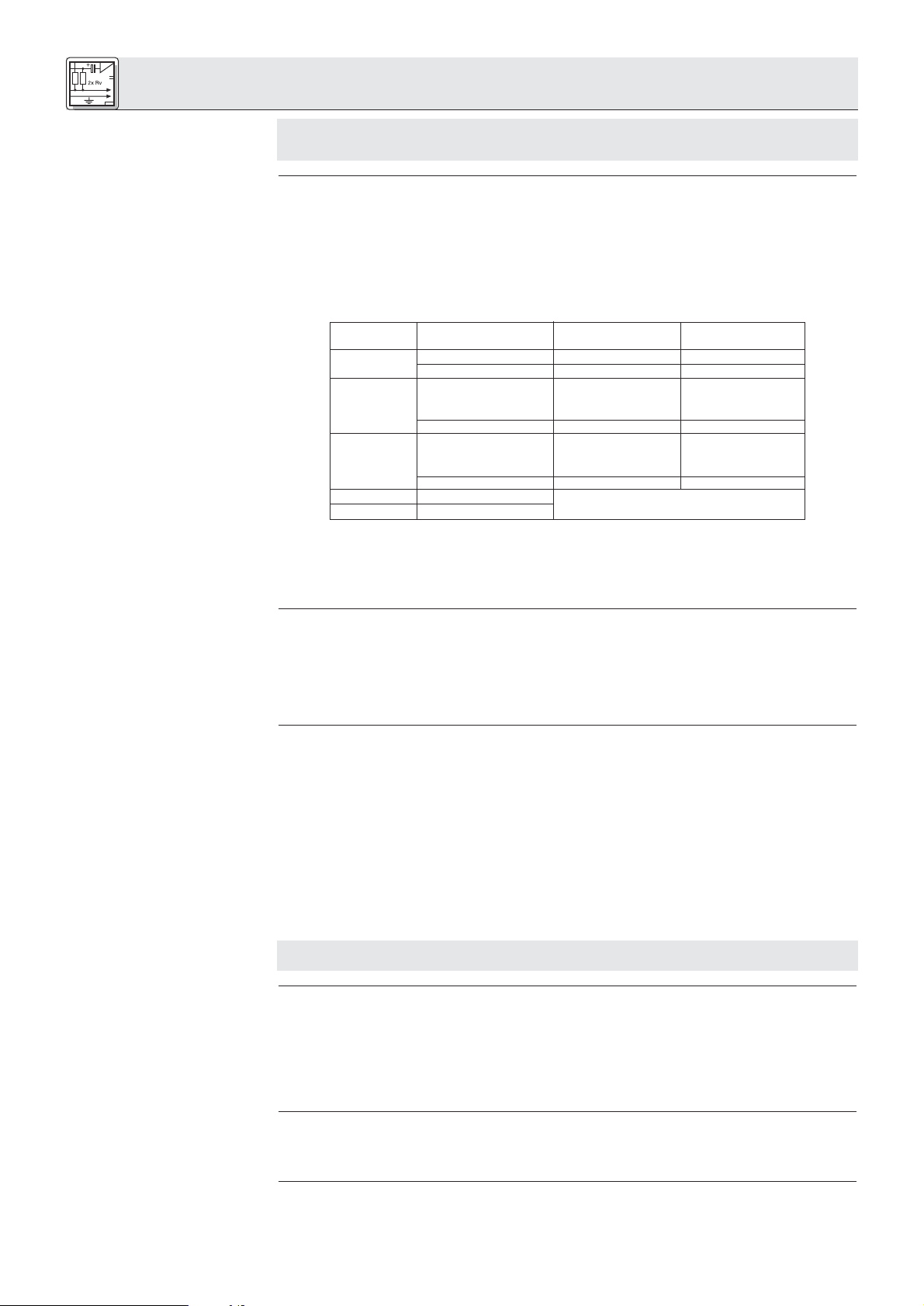
Die Zentrale CS 2 BU ist mit einem internen Equalizer (Tiefenabsenkung um 6 dB bei 500 Hz) und einem
Einschleifpunkt für einen externen Equalizer oder Feedback-Killer ausgestattet. Im Lieferzustand wirkt
3.1 Zentrale(n)
3.1.1 Zentrale(n) konfigurieren
5
Page 6
3 Inbetriebnahme
der interne Equalizer auf die eingebauten Lautsprecher aller angeschlossenen Sprechstellen und der
Einschleifpunkt liegt vor dem Line-Ausgang (LINE OUTPUT).
Drei Steckbrücken im Inneren der Zentrale erlauben Ihnen, diese Konfiguration zu ändern:
1. Lösen Sie die Befestigungsschrauben des Gehäusedeckels der Zentrale.
Siehe Fig. 5.
2. Nehmen Sie den Gehäusedeckel ab.
3. Stecken Sie die Steckbrücken entsprechend der gewünschten Konfiguration:
Tabelle 3: Interne Steckbrücken
Hinweis:
3.1.2 Kaskadieren mehrerer
Zentralen
Siehe Fig. 6.
3.1.3 Fernschalt- und
Fernanzeigeelemente ansch-
ließen
Siehe Fig. 7.
Steckbrücke Position wirkt auf: wirkt auf:
EFFECT Interner EQ
X9 1-2 (Werkseinstellung) LINE OUTPUT --
2-3 -- --
X10 1-2 eingebaute Laut- --
sprecher der
Sprechstellen
2-3 (Werkseinstellung) -- --
X7 1-2 (Werkseinstellung) -- eingebaute Laut-
sprecher der
Sprechstellen
2-3 -- -X10 1-2 eingebaute Lautsprecher der Sprechstellen
X7 1-2 (EFFECT und interner EQ in Serie)
Wenn sich sowohl X10 als auch X7 in Position 1-2 befinden, sind das externe Gerät und der interne
Equalizer in Serie geschaltet. Beide Geräte wirken dann auf die eingebauten Lautsprecher.
4. Schrauben Sie den Gehäusedeckel wieder auf das Gehäuse.
1. Verbinden Sie mittels eines optionalen Erweiterungskabels IC AS 8 die EXPANSION OUT-Buchse an
der ersten Zentrale ("Master") mit der EXPANSION IN-Buchse an der zweiten Zentrale ("Slave").
Die Zentrale, bei der nur die EXPANSION OUT-Buchse mit einem zweiten Gerät verbunden ist, wird automatisch als "Master" erkannt, dessen POWER-Schalter auch alle "Slave"-Zentralen ein/ausschaltet.
2. Verbinden Sie mittels eines weiteren optionalen Erweiterungskabels IC AS 8 die EXPANSION OUTBuchse an der zweiten Zentrale mit der EXPANSION IN-Buchse an der dritten Zentrale (und so weiter).
3. Verbinden Sie mit mindestens 0,5 mm2starkem Draht die 0V-Schraubklemmen aller Zentralen in Serie
miteinander.
An die EXPANSION IN- oder EXPANSION OUT-Buchse können Sie auch einen Ein/Aus-Schalter und
andere Fernschalt- und -anzeigeelemente an die Zentrale anschließen. Bei kaskadierten Zentralen können Sie dafür nur die EXPANSION IN-Buchse an der ”Master”-Zentrale verwenden.
Die EXPANSION-Buchsen sind wie folgt beschaltet:
Stift 2: Ein/Aus-Fernschalter. Solange Stift 2 mit DC INPUT 0V1 oder 0V2 verbunden ist, ist die
Zentrale eingeschaltet.
Stift 3+4: ERROR. Wenn eine interne Sicherung defekt ist, sind Stift 3 und 4 kurzgeschlossen.
Schließen Sie Ihre ERROR-Anzeige an Stift 3+4 an.
Stift 7+8: PRIORITY. An Stift 7 liegt eine Versorgungsspannung von +23 bis +36 V DC (je nach
Netzgerät) für eine externe Lampe, Relais o.ä. (Nur an EXPANSION OUT! An EXPANSION IN ist
Stift 7 frei.) Solange an einer Vorsitzendensprechstelle die Vorrangtaste gedrückt ist, liegt
Stift 8 an 0V.
Schließen Sie Ihr Relais o.ä. an Stift 7+8 an.
Wichtig!
3.1.4 Equalizer oder
Feedback-Killer anschließen
3.1.5 Andere externe Geräte
anschließen
3.2 Sprechstellen
3.2.1 Sprechstellen
konfigurieren
Siehe Fig. 8 und Tabelle 2
auf Seite 5.
6
Die übrigen Stifte dienen ausschließlich zum Kaskadieren mehrerer Zentralen. Wenn Sie an diese
Stifte externe Geräte anschließen, kann die Zentrale beschädigt werden.
An die EFFECT-Buchse an der Rückseite der Zentrale können Sie mittels eines Y-Kabels (nicht mitgeliefert) einen Equalizer oder Feedback-Killer anschließen.
Die EFFECT-Buchse ist wie folgt beschaltet:
Spitze: Return (vom Ausgang des Equalizers)
Ring: Send (zum Eingang des Equalizers)
Schaft: Masse
Schließen Sie Ihre externen Geräte an die entsprechenden Ein- bzw. Ausgänge an.
Beispiele: Externe Beschallungsanlage an LINE OUTPUT; Aufzeichnungsgerät an REC OUT; CD-Player
an AUX IN; drahtlose Mikrofonanlage (z.B. WMS 81 oder WMS 40 von AKG) an LINE INPUT.
1. Entfernen Sie die Abdeckung der Dipschalter.
2. Stellen Sie die Dipschalter 1 bis 8 entsprechend Ihrem Anlagenkonzept ein:
• Dipschalter Nr. 1 stellt die Einsatzschwelle des Gates ein. In Stellung "OFF" ist die Einsatzschwelle
hoch und das Mikrofon schaltet sich nur bei Besprechen aus nächster Nähe ein. Sobald das Mikrofon
offen ist, wird die Einsatzschwelle automatisch um 6 dB reduziert, damit sich das Mikrofon nicht
abschaltet, wenn der/die Delegierte leiser spricht oder sich vom Mikrofon weg bewegt.
Page 7

3 Inbetriebnahme
In der Stellung "ON" ist die Einsatzschwelle um 6 dB niedriger als in Stellung "OFF". Sobald das
Mikrofon offen ist, wird die Einsatzschwelle ebenfalls automatisch weiter reduziert.
• Dipschalter Nr. 2 schaltet die Zeit, während der das Mikrofon nach dem Ende einer Wortmeldung
offen bleibt, zwischen 12 Sekunden ("OFF") und 6 Sekunden ("ON") um.
• Dipschalter Nr. 3 schaltet die automatische Stummschaltung des Mikrofons ein oder aus. In Stellung
"OFF" schaltet sich das Mikrofon automatisch nach der mit Dipschalter Nr. 2 eingestellten Zeit ab.
In Stellung "ON" muss der/die Delegierte selbst auf die Sprechtaste drücken, um das Mikrofon abzuschalten.
• Dipschalter Nr. 4 erlaubt Ihnen, die Sprechstelle von der Teilnehmerbegrenzung auszunehmen. Dies
wird vor allem bei Vorsitzendensprechstellen erforderlich sein. In Stellung "OFF" kann der/die
Teilnehmer/in das Mikrofon jederzeit einschalten, unabhängig davon, wie viele Mikrofone bereits offen
sind.
In Stellung "ON" kann das Mikrofon nur dann aktiviert werden, wenn weniger als die an der Zentrale
eingestellte Anzahl von Mikrofonen offen sind.
• Dipschalter Nr. 5 schaltet zwischen manuellem Betrieb und Sprachsteuerung (Voice Activation-
Modus) um. In Stellung "OFF" kann der/die Delegierte das Mikrofon nur mit der Sprechtaste ein- und
ausschalten.
In Stellung "ON" kann der/die Delegierte ebenfalls die Sprechtaste benützen. Wenn jedoch die
Zentrale im Voice Activation-Modus arbeitet, schaltet sich das Mikrofon automatisch ein, sobald es
besprochen wird.
• Dipschalter Nr. 6 erlaubt Ihnen, die Sprechstelle von der Stummschaltung durch die Vorrangtaste an
einer Vorsitzendensprechstelle auszunehmen. Stellen Sie den Dipschalter Nr. 6 an allen wichtigen
Sprechstellen (Vorsitzende und dessen/deren Stellvertreter, wichtige Delegierte) auf "OFF", damit
diese Mikrofone auch dann offen bleiben, wenn der/die Vorsitzende die Vorrangtaste drückt.
In Stellung "ON" wird das Mikrofon stummgeschaltet, wenn der/die Vorsitzende die Vorrangtaste
drückt.
• Dipschalter Nr. 7 schaltet die Voice Zoom-Funktion ein oder aus. In Stellung "OFF" wird die
Verstärkung der Sprechstelle automatisch angehoben, wenn der/die Redner/in leiser spricht oder sich
vom Mikrofon weg bewegt, während das Signal komprimiert oder sogar begrenzt wird, wenn der/die
Redner/in sehr laut oder zu nahe am Mikrofon spricht.
In Stellung "ON" bleibt die Verstärkung der Sprechstelle konstant.
Siehe Fig. 8.
• Dipschalter Nr. 8: In Stellung "OFF" wird die jeweils letzte Lautstärkeeinstellung für die eingebauten
Lautsprecher und Kopfhörerausgänge gespeichert und bleibt auch nach dem Abschalten der Anlage
erhalten.
In Stellung "ON" wird die Lautstärke der Lautsprecher und Kopfhörerausgänge beim Einschalten der
Anlage automatisch auf Maximum gestellt.
Das Potentiometer P3 neben den Dipschaltern stellt den Ausgangspegel der Sprechstelle ein.
Der Ausgangspegel wurde werksseitig optimal an die Zentrale CS 2 BU angepasst. Verändern
Sie die Einstellung von P3 daher nicht, da eine Fehlanpassung zu Funktionsstörungen der
Anlage führen kann.
3. Schließen Sie die Abdeckung der Dipschalter.
1. Schneiden Sie mit Hilfe der Schablone in Fig. 13 aus der Tischplatte eine Öffnung aus.
2. Passen Sie die Sprechstelle in die Öffnung ein und fixieren Sie die Sprechstelle mit 4 geeigneten
Schrauben (nicht mitgeliefert).
Alle 4 Typen von Sprechstellen besitzen dieselben Anschlüsse für das Verbindungskabel CS MK:
Stift Nr. Farbe Funktion
1rosa Versorgungsspannung 36 V
2rot Versorgungsspannung 36 V
3 grau Masse 0V
4 blau Masse 0V
5 äussere Abschirmung Abschirmung
6 grün Teilnehmerbegrenzung
7 gelb Erkennung aktiver Mikrofone
8 Abschirmung grün/gelb Erkennung aktiver Mikrofone
9 weiß/grün Priority
10 braun/grün Voice Activation
11 weiß Sprachsignal +
12 braun Sprachsignal 13 Abschirmung weiß/braun Abschirmung
14 schwarz Lautsprecher +
15 violett Lautsprecher -
Wichtig!
3.2.2 Sprechstellen
"CS 2 DU fix"/"CS 2 CU fix"
einbauen
Siehe Fig. 13.
3.2.3 Sprechstellen anschließen
Die maximale Anzahl der Sprechstellen, die Sie an jede DELEGATE UNITS LINE-Buchse anschließen
können, hängt davon ab, welche Netzgeräte Sie an die Zentrale anschließen werden:
7
Page 8

3 Inbetriebnahme
Tabelle 4: Maximale Anzahl und
Verteilung von Sprechstellen in
Abhängigkeit von den
eingesetzten Netzgeräten
Wichtig!
3.2.4 Mikrofone anschließen
Hinweis:
Siehe Fig. 9.
3.3 Netzanschluss
Wichtig!
Netzgeräte Gesamt LINE 1 LINE 2 LINE 3 LINE 4
(Mögliche) / optimale Sprechstellenanzahl
1 x CS PS 20 40 (40) / 10 (0) / 10 (0) / 10 (0) / 10
2 x CS PS 20 80 (50) / 20 (30) / 20 (0) / 20 (0) / 20
1 x CS PS 100 200 50 50 50 50
1. Verbinden Sie mittels eines Kabels CS MK in der geeigneten Länge die DELEGATE UNITS LINE 1Buchse an der Zentrale mit einer der beiden Anschlussbuchsen an der ersten Sprechstelle.
2. Verbinden Sie die andere Anschlussbuchse an der ersten Sprechstelle mit einer der Anschlussbuchsen an der nächsten Sprechstelle und so weiter.
Wenn Sie die maximale Anzahl von Sprechstellen anschließen, verteilen Sie die Sprechstellen
gemäß Tabelle 4 auf die LINE-Buchsen 1 bis 4. Achten Sie auch darauf, dass die
Gesamtkabellänge von der Zentrale bis zur letzten Sprechstelle 100 m nicht übersteigt. Nur so
ist gewährleistet, dass alle Sprechstellen eine ausreichende Versorgungsspannung
(mind. 21 V DC) erhalten.
1. Wählen Sie für jede Sprechstelle den geeigneten Schwanenhals und die geeignete Mikrofonkapsel.
Nähere Informationen dazu finden Sie in der Bedienungsanleitung der Discreet Acoustics Modular
Serie.
Sie können alle Sprechstellen auch ohne Mikrofon, als reine Wiedergabeeinheit z.B. für SekretärInnen
oder StenographInnen einsetzen.
2. Schrauben Sie die Mikrofonkapsel auf den Schwanenhals.
3. Schrauben Sie den Schwanenhals in die Mikrofonbuchse an der Sprechstelle.
Kontrollieren Sie, ob die an Ihren Netzgeräten angegebene Netzspannung mit der Netzspannung
am Einsatzort übereinstimmt. Der Betrieb der Netzgeräte an einer anderen Netzspannung kann zu
Schäden am Gerät führen.
Siehe Fig. 10.
Siehe Fig. 11.
Wichtig!
AWenn Sie an die Zentrale nicht mehr als 30 bis 40 Sprechstellen angeschlossen haben, benöti-
gen Sie ein Netzgerät CS PS 20.
1. Öffnen Sie den 4-poligen Phoenix-Stecker (1) am Sekundärkabel des Netzgeräts und kontrollieren Sie,
ob die beiden Drahtbrücken (2) zwischen "0V1" und "0V2" sowie zwischen "+1" und "+2" eingesetzt
sind. Nur wenn die Drahtbrücken (2) eingesetzt sind, werden alle 4 Sprechstellenleitungen (LINE 1 bis
LINE 4) mit Strom versorgt.
2. Stecken Sie das Sekundärkabel des Netzgeräts an die 4-polige DC INPUT-Buchse (3) an der
Rückseite der Zentrale an.
3. Verbinden Sie das Netzgerät mit dem Stromnetz.
BWenn Sie an die Zentrale zwischen 40 und 80 Sprechstellen angeschlossen haben, benötigen
Sie zwei Netzgeräte CS PS 20.
1. Entfernen Sie die beiden Drahtbrücken (2) aus dem Phoenix-Stecker (1) des einen Netzgeräts.
2. Klemmen Sie den 4-poligen Phoenix-Stecker vom Sekundärkabel des zweiten Netzgeräts ab und
schließen Sie das Sekundärkabel des zweiten Netzgeräts an die Schraubklemmen "0V2" und "+2" an.
3. Stecken Sie den Phoenix-Stecker mit den Sekundärkabeln beider Netzgeräte an die 4-polige DC
INPUT-Buchse (3) an der Rückseite der Zentrale an.
4. Verbinden Sie die Netzgeräte mit dem Stromnetz.
CWenn Sie an die Zentrale zwischen 80 und 200 Sprechstellen angeschlossen haben, benötigen
Sie ein Netzgerät CS PS 100.
1. Bauen Sie das Netzgerät in das Rack ein.
Lassen Sie oberhalb und unterhalb des Netzgeräts je eine Rackebene frei, um eine ausreichende Luftzirkulation zur Kühlung des Netzgeräts zu gewährleisten.
2. Stecken Sie das Sekundärkabel des Netzgeräts an die DC INPUT-Buchse an der Rückseite der
Zentrale an.
3. Verbinden Sie das Netzgerät mit dem Stromnetz.
Hinweis:
Hinweis:
Das Netzgerät CS PS 20 besitzt keinen Ein/Ausschalter und verbraucht auch dann Strom, wenn die
Anlage ausgeschaltet ist. Wir empfehlen daher, diese Netzgeräte an einen Stromkreis mit
Ein/Ausschalter anzuschließen. Diesen Ein/Ausschalter können Sie als Hauptschalter für die gesamte
Anlage einsetzen.
Die EXPANSION-Buchsen führen keine Versorgungsspannung. Wenn Sie eine Anlage mit mehreren
Zentralen aufbauen, müssen Sie an jede Zentrale das (die) erforderliche(n) Netzgerät(e) anschließen.
8
Page 9

4 Betriebshinweise
Wenn Sie mehrere Zentralen zusammengeschaltet haben, schaltet der POWER-Schalter der "Master"Zentrale alle Zentralen ein. Die Bedienelemente sowie die Steuerfunktionen (Teilnehmerbegrenzung,
Priority etc.) jeder Zentrale (”Master” und ”Slaves”) wirken nur auf die an die jeweilige Zentrale angeschlossenen Sprechstellen. Das Audio-Summensignal aller Zentralen liegt an der LINE OUTPUT-Buchse
aller Zentralen an.
1. Anlagen mit CS PS 20: Wenn Sie die Netzgeräte an einen schaltbaren Stromkreis angeschlossen
haben, schalten Sie den Stromkreis ein.
Anlagen mit CS PS 100: Stellen Sie den Ein/Ausschalter an jedem Netzgerät auf " I", um das
Netzgerät einzuschalten.
2. Stellen Sie den POWER-Schalter an der (”Master”-)Zentrale auf "I", um die Zentrale(n) einzuschalten.
Die ON-LED leuchtet erst 2 Sekunden nach dem Einschalten auf. Während dieser Zeit wird die
Versorgungsspannung intern stabilisiert.
Falls die rote ERROR-LED aufleuchtet, kontrollieren Sie die Sicherungen und tauschen Sie defekte
Sicherungen aus (siehe Kapitel 4.8). Sollte beim Einschalten wieder die ERROR-LED aufleuchten,
wenden Sie sich an Ihre nächstgelegene AKG-Servicestelle.
1. Stellen Sie zum Ausschalten der Zentrale(n) den POWER-Schalter an der Frontplatte der (”Master” -)
Zentrale auf "0".
2. Anlagen mit CS PS 20: Wenn die Anlage länger als nur einige Stunden ausgeschaltet bleiben wird,
empfehlen wir, die Netzgeräte vom Stromnetz zu trennen (Netzstecker ziehen oder Hauptschalter ausschalten). Sie sparen damit Energie und Kosten.
Anlagen mit CS PS 100: Stellen Sie zum Ausschalten den Ein/Ausschalter jedes Netzgeräts Ihrer
Anlage auf "0".
1. Stellen Sie mit dem NOM LIMITATION-Wahlschalter an der Frontplatte der Zentrale die maximale
Anzahl von Mikrofonen, die gleichzeitig offen sein dürfen (1 bis 5), ein.
Wenn die eingestellte Anzahl offener Mikrofone erreicht wird, leuchtet die LIMIT-LED auf und es können keine weiteren Mikrofone aktiviert werden.
2. Zum Deaktivieren der Teilnehmerbegrenzung stellen Sie den NOM LIMITATION-Wahlschalter auf "∞" .
Hinweis:
4.1 Einschalten
4.2 Ausschalten
4.3 Teilnehmerbegrenzung
einstellen
Wenn Sie an die Zentrale 30 bis 40 Sprechstellen und nur ein Netzgerät CS PS 20 angeschlossen
haben, achten Sie darauf, den NOM LIMITATION-Wahlschalter auf höchstens "4" zu stellen. Bei "5"
könnten Fehlfunktionen auftreten.
Wenn der Kunde eine Teilnehmerbegrenzung auf 5 gleichzeitig offene Mikrofone wünscht, müssen Sie
zwei Netzgeräte CS PS 20 verwenden.
1. Zum Aktivieren der Sprachsteuerung drücken Sie die VOICE ACTIVATION-Taste an der Frontplatte der
Zentrale hinein.
Die Mikrofone jener Sprechstellen, an denen die VOICE ACTIVATION-Funktion ebenfalls aktiviert ist,
werden automatisch eingeschaltet, sobald die Mikrofone besprochen werden.
Solange ein Mikrofon offen ist, leuchten der rote LED-Ring am Mikrofon und die Kontroll-LED bei der
Sprechtaste.
2. Falls die Einsatzschwelle des Gates zu hoch oder zu niedrig ist, stellen Sie den Dipschalter Nr. 1 an
der Unterseite der Sprechstelle in die jeweils andere Position:
Schalterstellung OFF: Einsatzschwelle hoch
Schalterstellung ON: Einsatzschwelle niedrig
3. Zum Deaktivieren der Sprachsteuerung drücken Sie nochmals die VOICE ACTIVATION-Taste.
Die VOICE ACTIVATION-LED erlischt, die Mikrofone können nur durch Drücken der Sprechtaste eingeschaltet werden.
4. Wenn die Automute-Funktion aktiviert ist, schaltet sich das Mikrofon 6 oder 12 Sekunden nach Ende
der Wortmeldung automatisch stumm.
5. Ist die Automute-Funktion deaktiviert, muss der/die Delegierte selbst nochmals die Sprechtaste
drücken, um das Mikrofon stummzuschalten.
Stellen Sie mit dem SPEAKERS OUT-Regler an der Frontplatte der Zentrale die maximale Lautstärke der
in den Sprechstellen eingebauten Lautsprecher ein. Dies ist die höchste Lautstärke, die Sie mit den
Lautstärketasten an den Sprechstellen einstellen können.
Wenn Sie an die Zentrale 30 bis 40 Sprechstellen und ein Netzgerät CS PS 20 angeschlossen haben,
achten Sie darauf, die Lautstärke höchstens auf 70% (ca. ”2 Uhr”) einzustellen. Bei höheren Einstellungen
könnten Fehlfunktionen auftreten.
Wenn der Kunde höhere Lautstärken wünscht, müssen Sie zwei Netzgeräte CS PS 20 verwenden.
Hinweis:
4.4 Mikrofone aktivieren und
deaktivieren (Voice Activation
und Automute)
Siehe Fig. 8.
Siehe auch Kapitel 3.2.1
Sprechstellen konfigurieren.
Siehe auch Kapitel 3.2.1,
Dipschalter Nr. 2 und 3.
4.5 Lautsprecher einstellen
Hinweis:
Stellen Sie an den Sprechstellen das Kompressionsverhältnis der Voice Zoom-Funktion ein:
Potentiometer B an der Unterseite der Sprechstelle stellt das Kompressionsverhältnis der Voice Zoom-
Funktion ein. Am linken Anschlag beträgt das Kompressionsverhältnis ca. 1:1, das Mikrofonsignal wird
also kaum komprimiert. Am rechten Anschlag beträgt das Kompressionsverhältnis 2:1. Leise Signale
werden automatisch im Pegel angehoben, während laute Signale abgeschwächt werden.
1. Solange der rote LED-Ring am Mikrofon und die Kontroll-LED der Sprechtaste leuchten, ist das
Mikrofon offen.
2. Mit den Lautstärketasten kann der/die Teilnehmer/in die Lautstärke der eingebauten Lautsprecher
selbst einstellen, allerdings nur bis zu dem an der Zentrale eingestellten Maximalwert.
4.6 Voice Zoom einstellen
Siehe Fig. 4.
4.7 Hinweise zum Betrieb der
Sprechstellen
9
Page 10
4 Betriebshinweise
3. Wenn der/die Vorsitzende die Delegierten zur Ordnung rufen möchte, kann er/sie durch Drücken und
Halten der Vorrangtaste alle anderen Mikrofone stummschalten (mit Ausnahme jener, bei denen die
Vorrangfunktion deaktiviert ist). Die Mikrofone können sich erst dann wieder einschalten, wenn der/die
Vorsitzende die Vorrangtaste wieder loslässt. Bei Anlagen mit mehreren Zentralen schaltet die
Vorrangtaste nur jene Mikrofone stumm, die an die selbe Zentrale angeschlossen sind wie die
Sprechstelle, an der die Vorrangtaste gedrückt wird.
4.8 Interne Sicherungen der
Zentrale austauschen
Siehe Fig. 5.
5 Reinigung
Wichtig!
Jede Sprechstellenleitung LINE 1 bis LINE 4 ist mit einer eigenen Sicherung des Typs "T4A träge", die
Hauptplatine mit einer Sicherung des Typs ”T1A träge” abgesichert.
• Wenn die ERROR ∑-LED an der Rückseite der Zentrale sowie die rote ERROR-LED in der OUTPUT
CONTROL-Sektion an der Frontplatte aufleuchten, ist die Sicherung der Hauptplatine defekt.
• Wenn sowohl die ERROR-LED an der Frontplatte als auch die ERROR ∑-LED und die ERROR-LED
neben einer der LINE-Buchsen an der Rückseite der Zentrale aufleuchtet, ist die Sicherung der betreffenden Sprechstellenleitung defekt.
Tauschen Sie die defekte Sicherung aus:
1. Schalten Sie die Zentrale und die daran angeschlossenen Netzgeräte aus.
2. Lösen Sie die Befestigungsschrauben des Gehäusedeckels der Zentrale.
3. Nehmen Sie den Gehäusedeckel ab.
4. Nehmen Sie die defekte Sicherung ( ) aus der Halterung heraus.
5. Setzen Sie eine neue Sicherung desselben Typs ( : T4A träge für LINE 1 bis 4, : T1A träge
für die Hauptplatine) ein.
6. Schrauben Sie den Gehäusedeckel wieder auf das Gehäuse.
1. Schalten Sie die Zentrale aus und trennen Sie das/die Netzgerät/e vom Stromnetz.
2. Reinigen Sie die Oberflächen der Zentrale, der Netzgeräte und der Sprechstellen mit einem mit
Wasser befeuchteten, aber nicht nassen Tuch.
Verwenden Sie keinesfalls scharfe oder scheuernde Reinigungsmittel sowie keine, die Alkohol
oder Lösungsmittel enthalten, da diese den Lack sowie die Kunststoffteile beschädigen könnten.
6 Fehlerbehebung
Fehler
Kein Ton.
Wenn im Voice Activation-Modus ein Mikrofon
besprochen wird, schalten sich alle Mikrofone
ein.
Das System funktioniert, aber einige
Sprechstellen nicht.
Mögliche Ursache
1. Netzgerät(e) nicht mit dem Stromnetz verbunden.
2. Netzgerät(e) nicht mit Zentrale(n) verbunden.
3. Netzgerät(e) und/oder Zentrale(n) ausgeschaltet.
4. MIC DELEGATES LEVEL-Regler steht auf
Null.
5. Eine oder mehrere interne Sicherungen der
Zentrale sind defekt.
1. Gate-Einsatzschwelle zu niedrig eingestellt.
2. Zu hoher Pegel der eingebauten
Lautsprecher der Sprechstellen löst Gate
durch mechanische Schalleitung aus.
1. Keine Spannung an DC INPUT +1 oder +2.
2. Wenn Sie zwei CS PS 20 verwenden, ist
eines defekt.
3. Eine der internen Sicherungen defekt (entsprechende ERROR-LED leuchtet).
Abhilfe
1. Netzgerät(e) an das Stromnetz anschließen.
2. Netzgeräte mit Zentrale(n) verbinden.
3. Netzgerät(e) und/oder Zentrale(n) einschalten.
4. MIC DELEGATES LEVEL-Regler aufdrehen.
5. Sicherung(en) austauschen.
1. Dipschalter Nr. 1 an Sprechstellen auf
"OFF" ("1") stellen.
2a.SPEAKERS OUT-Regler an Zentrale
zurückdrehen.
2b
.Anstelle der eingebauten Lautsprecher
externe Beschallungsanlage verwenden.
2c.Kopfhörer anstelle der eingebauten
Lautsprecher verwenden.
2d.
Voice Activation abschalten.
1. Siehe Kapitel 3.3.
2. Defektes Netzgerät ersetzen.
3. Sicherung tauschen (Kapitel 4.8).
10
Page 11
7 Technische Daten
7.1 Zentrale CS 2 BU
Eingänge
LINE 1-4
Anschluss 4 x 15-pol. Sub-D HD (männl.)
Eingangsnennpegel +10 dBu
Art elektronisch symmetriert
Max. Eingangspegel
für <1% Klirrfaktor +23 dBu
LINE INPUT
Anschluss XLR 3-polig (weibl.)
Eingangsnennpegel ±0 dBu
Art trafosymmetriert
Eingangsimpedanz bei 1 kHz 30 kΩ
Max. Eingangspegel
für <1% Klirrfaktor +17 dBu
AUX IN
Anschluss 2 x Cinch (weibl.)
Eingangsnennpegel -10 dBu
Art asymmetrisch
Eingangsimpedanz bei 1 kHz 33 kΩ
Max. Eingangspegel
für <1% Klirrfaktor +5 dBu
Ausgänge
REC OUT
Anschluss 2 x Cinch (weibl.)
Nennpegel ±0 dBu
Max. Ausgangspegel
bei 1% Klirrfaktor 17 dBu
Übertragungsbereich 15 – 50.000 Hz
Min. Lastimpedanz 33 Ω
Klirrfaktor (THD & N) bei 1 kHz 0,01%
Geräuschspannungsabstand 62 dB
LINE OUTPUT
Anschluss XLR 3-polig (männl.)
Nennpegel ±0 dBu
Max. Ausgangspegel
bei 1% Klirrfaktor +10 dBu
Übertragungsbereich 20 – 40.000 Hz
Min. Lastimpedanz 300 Ω
Klirrfaktor (THD & N) bei 1 kHz 0,02%
Geräuschpegelabstand 88 dB
Kopfhörer
Anschluss 6,3 mm-Stereoklinkenbuchse
Nennpegel ±0 dBu
Max. Ausgangspegel
bei 1% Klirrfaktor +14 dBu
Min. Lastimpedanz 150 Ω
Klirrfaktor (THD & N) bei 1 kHz 0,05%
Geräuschpegelabstand 70 dB
EFFECT
Anschluss 6,3 mm-Stereoklinkenbuchse
Nennpegel ±0 dBu
Eingangsimpedanz <4,7 kΩ
Max. Ausgangspegel
bei 1% Klirrfaktor +14 dBu
Min. Lastimpedanz 220 Ω
Gesamtsystem
Betriebsspannung 23 – 36 V DC
Stromaufnahme
bei maximaler Spannung 170 – 200 mA
Max. Leistungsaufnahme 7,2 W
Abmessungen (LxBxH) 170 x 430 x 40 mm
Gewicht brutto/netto 3,2 kg/2,5 kg
Lieferumfang Zentrale ohne Netzgerät
Bestellnummern
CS 2 BU 6000H3400
Optionales Zubehör
CS PS 20 6000H3600
CS PS 100 6000H3601
CS MK AC-EU 6000H3602
CS MK AC-US 6000H3603
CS MK AC-UK 6000H3604
7.2 Sprechstellen CS 2 DU / CS 2 CU
Geeignete Mikrofone nur GN 30 CS oder GN 50 CS
mit CK 31, CK 32, CK 33,
CK 47 oder CK 80
Eingang
Art asymmetrisch, mit DC-
Impedanz 1,5 kΩ
Speisespannung für Mikrofonkapsel 5,5 V DC
Ausgänge
Line
Anschluss 2 x 15-pol. Sub-D HD (männl.)
Art trafosymmetriert, erdfrei
Nennpegel +10 dBu
Übertragungsbereich 55 – 35.000 Hz
Geräuschspannungsabstand 81 dB
Systemkompatibilität kompatibel mit CS 1
Klirrfaktor (THD & N) bei 1 kHz 0,25%
Äquivalentes Eingangsrauschen,
mit Noise Gate, 22 Hz – 22 kHz -105 dBu
Kopfhörer und Lautsprecher
Anschluss 2 x 3,5 mm-Mono-
Ausgangsleistung für <1% Klirrfaktor 0,48 W (Lautsprecher)
Übertragungsbereich 30 – 45.000 Hz
Geräuschspannungsabstand 85 dB
Klirrfaktor (THD & N) bei 1 kHz 0,25%
Äquivalentes Eingangsrauschen,
mit Noise Gate, 22 Hz – 22 kHz -105 dBu
Digitalpotentiometer-Absenkung 32 Stufen von 0 bis –82 dB
Gesamtsystem
Einstellbare Funktionen Voice Activation – Empfindlichkeit
Voice Activation – Haltezeit
Mikro – Abschaltautomatik
Teinehmerbegrenzung
Voice Activation ein/aus
Vorrang ja/nein
Kompression/linear
Digipot Reset beim Einschalten oder
Speicherung der letzten Einstellung
Kompressionsverhältnis
Farbe AKG Blue Line grau / mattschwarz
Lieferumfang Sprechstelle ohne Kabel und Mikrofon
Bestellnummern
CS 2 CU 2770Z0001
CS 2 DU 2770Z0002
CS 2 CU fix 2770Z0003
CS 2 DU fix 2770Z0004
Optionales Zubehör
CS MK 1.25 fm – Verbindungskabel 1,25 m 2770Z0011
CS MK 2.5 fm - Verbindungskabel 2,5 m 2770Z0012
CS MK 5 fm - Verbindungskabel 5 m 2770Z0013
CS MK 10 fm - Verbindungskabel 10 m 2770Z0014
CS MK 20 fm - Verbindungskabel 20 m 2770Z0015
CK 31 – Discreet Acoustics Mikrofonkapsel 2765Z0020
CK 32 – Discreet Acoustics Mikrofonkapsel 2765Z0021
CK 33 – Discreet Acoustics Mikrofonkapsel 2765Z0022
CK 47 – Discreet Acoustics Mikrofonkapsel 2765Z0023
CK 80 – Discreet Acoustics Mikrofonkapsel 2765Z0024
GN 30 CS – Schwanenhals ca. 30 cm lang 2765Z0027
GN 50 CS – Schwanenhals ca. 50 cm lang 2765Z0028
CS MK 1/2 – 100 m Kabel mit 9,5 mm Durchmesser
für fixe Installation 6000H3612
CS MK 100 oc/mob – 100 m Kabel mit 7 mm Durchmesser
für mobile Installation 6000H3611
CS CON fm/fi – Sub D-Stecker, weibl.,
für fixe Installation 6000H3620
CS CON m/fi - wie CS CON fm/fi, männl. 6000H3621
CS CON fm/mob - Stecker (weibl.) f. mobile Anw. 6000H3622
CS CON m/mob - Stecker (männl.) f. mobile Anw. 6000H3623
CS CON floor/m/fi - Stecker (männl.) f. Bodeneinbau
CS CON split2/m/mob - Verteilerstecker 2-fach 6000H3625
CS CON split4/Mm/mob - Verteilerstecker 4-fach 6000H3626
K 10 – Konferenz-Kopfhörer 2246Z0013
K 11 – Ein-Ohr-Kopfhörer 2724Z0011
Speisespannung
klinkenbuchse
6000H3624
11
Page 12

Table of Contents
1 Safety and Environment . . . . . . . . . . . . . . . . . . . . . . . . . . . . . . . . . . . . . . . . . . . . . . . . . 12
1.1 Safety. . . . . . . . . . . . . . . . . . . . . . . . . . . . . . . . . . . . . . . . . . . . . . . . . . . . . . . . . . . . 12
1.2 Environment . . . . . . . . . . . . . . . . . . . . . . . . . . . . . . . . . . . . . . . . . . . . . . . . . . . . . . . 13
2 Description. . . . . . . . . . . . . . . . . . . . . . . . . . . . . . . . . . . . . . . . . . . . . . . . . . . . . . . . . . . . 13
2.1 Introduction . . . . . . . . . . . . . . . . . . . . . . . . . . . . . . . . . . . . . . . . . . . . . . . . . . . . . . . 13
2.2 Unpacking . . . . . . . . . . . . . . . . . . . . . . . . . . . . . . . . . . . . . . . . . . . . . . . . . . . . . . . . 13
2.3 Optional Accessories . . . . . . . . . . . . . . . . . . . . . . . . . . . . . . . . . . . . . . . . . . . . . . . . 13
2.4 CS 2 BU Base Unit. . . . . . . . . . . . . . . . . . . . . . . . . . . . . . . . . . . . . . . . . . . . . . . . . . 13
2.4.1 Front Panel . . . . . . . . . . . . . . . . . . . . . . . . . . . . . . . . . . . . . . . . . . . . . . . . . . . 13
2.4.2 Rear Panel. . . . . . . . . . . . . . . . . . . . . . . . . . . . . . . . . . . . . . . . . . . . . . . . . . . . 14
2.5 Microphone Stations . . . . . . . . . . . . . . . . . . . . . . . . . . . . . . . . . . . . . . . . . . . . . . . . 14
2.5.1 Top Panel . . . . . . . . . . . . . . . . . . . . . . . . . . . . . . . . . . . . . . . . . . . . . . . . . . . . 15
2.5.2 Bottom Panel. . . . . . . . . . . . . . . . . . . . . . . . . . . . . . . . . . . . . . . . . . . . . . . . . . 15
Block Diagram. . . . . . . . . . . . . . . . . . . . . . . . . . . . . . . . . . . . . . . . . . . . . . . . . . . . . . . . . 63
3 Setting Up . . . . . . . . . . . . . . . . . . . . . . . . . . . . . . . . . . . . . . . . . . . . . . . . . . . . . . . . . . . . 16
3.1 Base Unit(s) . . . . . . . . . . . . . . . . . . . . . . . . . . . . . . . . . . . . . . . . . . . . . . . . . . . . . . . 16
3.1.1 Setting up the Base Unit(s) . . . . . . . . . . . . . . . . . . . . . . . . . . . . . . . . . . . . . . . 16
3.1.2 Connecting Several Base Units Together . . . . . . . . . . . . . . . . . . . . . . . . . . . . . 16
3.1.3 Connecting Remote Controls and Indicators . . . . . . . . . . . . . . . . . . . . . . . . . . 16
3.1.4 Connecting an Equalizer or Feedback Killer . . . . . . . . . . . . . . . . . . . . . . . . . . . 16
3.1.5 Connecting other External Devices . . . . . . . . . . . . . . . . . . . . . . . . . . . . . . . . . 16
3.2 Microphone Stations . . . . . . . . . . . . . . . . . . . . . . . . . . . . . . . . . . . . . . . . . . . . . . . . 16
3.2.1 Setting up Microphone Stations . . . . . . . . . . . . . . . . . . . . . . . . . . . . . . . . . . . . 16
3.2.2 Installing "CS 2 DU fix" and CS 2 CU fix" Microphone Stations . . . . . . . . . . . . 17
3.2.3 Connecting Microphone Stations . . . . . . . . . . . . . . . . . . . . . . . . . . . . . . . . . . . 17
3.2.4 Connecting Microphones. . . . . . . . . . . . . . . . . . . . . . . . . . . . . . . . . . . . . . . . . 18
3.3 Connecting to Power . . . . . . . . . . . . . . . . . . . . . . . . . . . . . . . . . . . . . . . . . . . . . . . . 18
4 Operating Notes. . . . . . . . . . . . . . . . . . . . . . . . . . . . . . . . . . . . . . . . . . . . . . . . . . . . . . . . 19
4.1 Powering Up . . . . . . . . . . . . . . . . . . . . . . . . . . . . . . . . . . . . . . . . . . . . . . . . . . . . . . 19
4.2 Powering Down . . . . . . . . . . . . . . . . . . . . . . . . . . . . . . . . . . . . . . . . . . . . . . . . . . . . 19
4.3 Setting NOM Limitation . . . . . . . . . . . . . . . . . . . . . . . . . . . . . . . . . . . . . . . . . . . . . . 19
4.4 Activating and Deactivating Microphones (Voice Activation and Automute). . . . . . . . 19
4.5 Setting Loudspeaker Levels . . . . . . . . . . . . . . . . . . . . . . . . . . . . . . . . . . . . . . . . . . . 19
4.6 Setting Voice Zoom . . . . . . . . . . . . . . . . . . . . . . . . . . . . . . . . . . . . . . . . . . . . . . . . . 19
4.7 Notes on Using Microphone Stations . . . . . . . . . . . . . . . . . . . . . . . . . . . . . . . . . . . . 19
4.8 Replacing Internal Fuses . . . . . . . . . . . . . . . . . . . . . . . . . . . . . . . . . . . . . . . . . . . . . 20
Page
5 Cleaning . . . . . . . . . . . . . . . . . . . . . . . . . . . . . . . . . . . . . . . . . . . . . . . . . . . . . . . . . . . . . . 20
6 Troubleshooting. . . . . . . . . . . . . . . . . . . . . . . . . . . . . . . . . . . . . . . . . . . . . . . . . . . . . . . . 20
7 Specifications . . . . . . . . . . . . . . . . . . . . . . . . . . . . . . . . . . . . . . . . . . . . . . . . . . . . . . . . . 21
7.1 CS 2 BU Base Unit. . . . . . . . . . . . . . . . . . . . . . . . . . . . . . . . . . . . . . . . . . . . . . . . . . 21
7.2 CS 2 DU / CS 2 CU Microphone Stations . . . . . . . . . . . . . . . . . . . . . . . . . . . . . . . . . 21
1 Safety and Environment
1.1 Safety
1. Do not spill any liquids on the equipment and do not drop any objects through the ventilation slots in
the equipment.
2. The equipment may be used in dry rooms only.
3. The equipment may be opened, serviced, and repaired by authorized personnel only. the equipment
contains no user-serviceable parts.
4. Before connecting the equipment to power, check that the AC mains voltage stated on the supplied
AC adapter is identical to the AC mains voltage available where you will use the equipment.
5. Operate the equipment with the supplied CS PS 20 or CS PS 100 power supply with a secondary voltage of 23 to 36 VDC only. Using power supplies with an AC output and/or a different output voltage
may cause serious damage to the unit.
6. If any solid object or liquid penetrates into the equipment, shut down the sound system immediately.
Disconnect the power cable from the power outlet immediately and have the equipment checked by
AKG service personnel.
7. If you will not use the equipment for a long period of time, disconnect the power cable from the power
outlet. Please note that the equipment will not be fully isolated from power when you set the power
switch to OFF.
8. Do not place the equipment near heat sources such as radiators, heating ducts, or amplifiers, etc. and
do not expose it to direct sunlight, excessive dust, moisture, rain, mechanical vibrations, or shock.
9. To avoid hum or interference, route all audio lines, particularly those connected to the microphone
inputs, away from power lines of any type. If you use cable ducts, be sure to use separate ducts for
the audio lines.
10.Clean the equipment with a moistened (not wet) cloth only. Be sure to disconnect the power cable
from the power outlet before cleaning the equipment! Never use caustic or scouring cleaners or cleaning agents containing alcohol or solvents since these may damage the enamel and plastic parts.
12
Page 13

1 Safety and Environment
1. The CS PS 20 power supply will draw a small aount of current even when the equipment is switched
off. To save energy, disconnect the power cable from the power outlet if you will leave the equipment
unused for a long period of time.
2. When scrapping the equipment, separate the case, circuit boards, and cables, and dispose of all components in accordance with local waste disposal rules.
Thank you for purchasing an AKG product. This Manual contains important instructions for setting up and
operating your equipment. Please take a few minutes to read the instructions below carefully before
operating the equipment.
Please keep the Manual for future reference.
The CS 2 Conference System from AKG provides excellent audio quality and uses single-cable technology for easy installation. The system is fully modular so you can easily design a conference system that
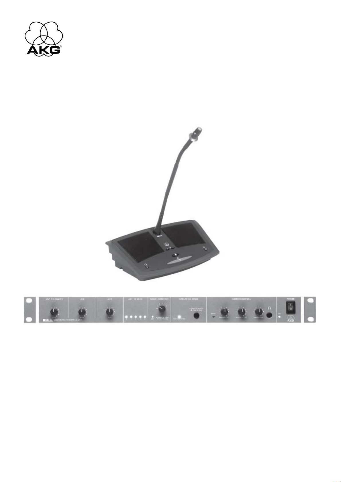
meets your customer's requirements. You can choose from various connecting cables, desktop or flushmount Microphone Stations, power supplies, goosenecks, and microphone capsules.
The CS 2 BU Base Unit powers and controls up to 200 Microphone Stations. For systems with up to 40
Microphone Stations you will need a CS PS 20 power supply, while a CS PS 100 power supply can power
systems with up to 200 Microphone Stations.
Both the CS 2 CU Chair Station and the CS 2 DU Delegate Station provide a patented screw-on connector for a GN 30 CS (12-in./30-cm) or GN 50 CS (20-in./50-cm) gooseneck. You can connect to the gooseneck any one of five different Discreet Acoustics Series microphone capsules from AKG.
Check that the shipment contains all of the seven components listed below in the quantities you ordered. Should anything be missing, please contact you local AKG Distributor.
1.2 Environment
2 Description
2.1 Introduction
2.2 Unpacking
1. CS 2 BU Base Unit
2. Power supply: CS PS 20 or CS PS 100
3. Power cable: CS MK AC-EU, CS MK AC-US, or CS MK AC-UK
4. Microphone Stations: CS 2 DU, CS 2 DU fix, CS 2 CU, or CS 2 CU fix
5. Connecting cables: CS MK 1.25 fm, CS MK 2.5 fm, CS MK 5 fm, CS MK 10 fm, or CS MK 20 fm
6. Goosenecks: GN 30 CS or GN 50 CS
7. Microphone capsules: CK 31, CK 32, CK 33, CK 47, or CK 80
For a list of optional accessories for the CS 2 Conference System and their order numbers refer to sections 7.1 and 7.2 on page 21.
MIC DELEGATES LEVEL: This rotary control sets the level of all microphones.
LINE LEVEL: This rotary control sets the level of the balanced LINE INPUT for external audio sources.
AUX LEVEL: This rotary control sets the level of the unbalanced AUX input.
ACTIVE MICS: The blue LEDs 1 through 4 illuminate to indicate the microphone on one of the Microphone
Stations is open. If more than five microphones are open simultaneously, LED 5 will illuminate.
NOM LIMITATION: The NUMBER OF OPEN MICROPHONES rotary control sets the maximum number
of microphones that may be open at any time. The red LIMIT LED will illuminate every time the number
of open microphones reaches the limit you set.
OPERATION MODE: Pushing this button IN places the Base Unit in Voice Activation mode. A micro-
phone channel will become active as soon as the microphone is talked into. The VOICE ACTIVATION
LED lights to indicate the Base Unit is in Voice Activation mode.
As long as the button is OUT, microphones can only be activated by pressing the PTT switch on the
appropriate Microphone Station. In this mode, the VOICE ACTIVATION LED will be dark.
ERROR: This red LED illuminates to indicate that one of the fuses on Microphone Station lines LINE 1
through LINE 4 or the fuse on the motherboard has blown. For details refer to section 4.8.
2.3 Optional Accessories
2.4 CS 2 BU Base Unit
2.4.1 Front Panel
Refer to fig. 1.
SPEAKERS OUT: This rotary control sets the maximum volume level of the built-in loudspeakers and the
maximum headphones level on ALL Microphone Stations.
BALANCED OUT: This rotary control sets the level of the balanced LINE OUTPUT.
HEADPHONES OUT: This rotary control sets the volume level of the headphone output ".
": 1/4" jack for connecting a pair of headphones.
POWER: Switches power to the Base Unit on ("I") and of ("0").
ON: This green LED illuminates to indicate that power to the Base Unit is ON.
13
Page 14

2 Description
Note:
2.4.2 Rear Panel
Refer to fig. 2.
Note:
The ON LED will illuminate about 2 seconds after you switched the power on. During this time, the
supply voltage is internally stabilized.
EXPANSION IN/ OUT: These two 8-pin Mini DIN jacks (also known as Hosiden or S-VHS connectors)
allow you to connect several Base Units together if you need to install a system with more than 200
Microphone Stations. To connect two Base Units, you will need an optional IC AS 8 expansion cable
and AWG 20 (0.5 mm2) or heavier wire to connect the 0V terminals on the two Base Units together.
The Base Unit with a cable connected to EXPANSION OUT only is automatically detected as the
master whose POWER switch turns power to the master and all slave Base Units on and off. The
audio signals of all Base Units are summed and routed to the LINE output connectors on all Base
Units. However, the control signals for NOM limitation, priority, etc. are not summed. Therefore, each
Base Unit only controls the Microphone Stations connected to it.
You can also use the EXPANSION jacks to connect a remote on/of switch or other remote controls or
indicators. For details, refer to section 3.1.3.
LINE OUTPUT: This transformer balanced 3-pin XLR connector (pin 2 hot) provides the summed output
signal of all input channels. Its nominal level is 0 dBu and the output level can be set with the front
panel BALANCED OUT control.
REC OUT L/R: These two RCA jacks provide the same unbalanced mono signal for cassette deck or
other recording devise. The signal at the REC OUT jacks is the summed output signal of all input channels.
The red trimmer pot to the left of the REC OUT jacks sets the output level of the two jacks. The REC
OUT level setting is not affected by the front panel OUTPUT CONTROL section controls.
AUX IN L/R: These two RCA jacks let you connect an audio source such as a CD player for important
messages.
Stereo input signals will be summed to mono.
Signal present at the AUX IN jacks will NOT mute the microphones.
EFFECT: This 1/4" TRS jack allows you to insert an outboard equalizer or feedback killer into the signal
path to reduce the risk of feedback in acoustically difficult rooms.
Note the pinout of the insert:
Tip: Return
Ring: Send
Shaft: Ground
Table 1: 15-pin D-Sub pinout and
connecting cable color code.
LINE INPUT: This balanced 3-pin XLR connector (pin 2 hot) lets you connect any transformer balanced
line level audio source, e.g., a video codec or a wireless microphone system.
DELEGATE UNITS/ LINE 1-4: You can connect up to 50 Microphone Stations to each of the 15-pin
D-Sub connectors LINE 1 though LINE 4. The type and number of power supplies you will need
depends on the total number of your Microphone Stations and the overall length of connecting cables
must not exceed 330 feet (100 m) per LINE connector.
The red ERROR LED next to each LINE connector illuminates to indicate the internal fuse (T4A slowblow) on the appropriate interface has blown. For details refer to section 4.8.
Pin No. Color Function
1 PINK Power, 23 to 36V
2 RED Power, 23 to 36V
3 GREY Ground 0V
4 BLUE Ground 0V
5 EXTERNAL SHIELD Shield
6 GREEN NOM limitation
7 YELLOW Active mic detection
8 GREEN/YELLOW SHIELD Active mic detection
9 WHITE GREEN Priority
10 BROWN GREEN Voice Activation
11 WHITE Speech signal inphase
12 BROWN Speech signal return
13 WHITE/BROWN SHIELD Shield
14 BLACK Loudspeaker inphase
15 VIOLET Loudspeaker return
ERROR Σ: This red LED illuminates whenever the front panel ERROR LED illuminates. If only these two
LEDs and none of the EROR LEDs next to the LINE connectors illuminate the fuse on the motherboard
(T1A slow-blow) has blown. For details refer to section 4.8.
GND/0V: This jumper connects chassis ground to the rack. Remove the jumper to interrupt ground loops.
2.5 Microphone Stations
14
DC INPUT: 4-pin Phoenix connector for one or two power supplies, depending on the number of
Microphone Stations your system uses.
Terminals 0V1 and +1 power the Microphone Stations connected to LINE 1 and LINE 2, terminals 0V2
and +2 the Microphones Stations on LINE 3 and LINE 4.
The CS 2 DU Delegate Station and CS 2 CU Chair Station provide basically the same functions and controls. In addition, the Chair Station features a priority button for muting all other microphones.
Page 15
2 Description
Microphone input: Gold plated, threaded mini jack for connecting a GN 30 CS or GN 50 CS goose-
neck with a Discreet Acoustics Series microphone capsule.
+/-: These two keys set the volume level of the built-in loudspeakers in 31 steps. "+" increases and
"-" decreases the volume. The last "-" position (-82 dB) is equivalent to OFF.
To prevent feedback, the built-in loudspeakers are muted automatically whenever the microphone
comes on.
": These two mini jacks allow you to connect two pairs of headphones.
The built-in loudspeakers are automatically muted as soon as you connect a pair of headphones. The
headphone signal, however, is NOT muted when the microphone comes on. (Normally there is no risk
of feedback from the headphones to the microphone.)
PTT switch and status LED: The red PTT switch activates and deactivates the microphone. When
NOM Limitation is active, the microphone will not come on unless the number of microphones already
open is lower than the limit you have set. The status LED will illuminate for as long as the microphone
is open.
Priority button (CS 2 CU only): The chairperson can mute all open microphones and activate the
microphone on the Chair Station by pressing and holding down the black priority button. As soon as
the chairperson releases the priority button, the microphone on the Chair Station will be muted and
all other microphones can be activated again.
Connectors: Each Microphone Station provides two 15-pin male D-Sub connectors for connecting
the microphone Station to the Base Unit and/or other Microphone Stations.
Dip switches 1-8: The dip switches are located beneath a removable cover and set the following
functions:
Switch Position
Switch No. Function OFF (1-8) ON
1 Gate threshold High Low
2 Hold time 12 secs. 6 secs.
3 Auto mute Active Inactive
4 NOM Limitation Inactive Active
5Voice Activation Inactive Active
6 Chairperson override Inactive Active
7 Compression Active Linear
8 Loudspeaker level memory Active Inactive
2.5.1 Top Panel
Refer to fig. 3 (CS 2 CU shown).
2.5.2 Bottom Panel
Refer to fig. 4.
Table 2: Dip switch functions.
Trimmer pot A: Sets the input sensitivity.
Trimmer pot B: Sets the Voice Zoom compression ratio.
Trimmer pot P3: Sets the Microphone Station output level. The output level has been factory preset for
optimum matching to the CS 2 BU Base Unit. Be sure not to change the setting of P3 because mismatching may cause system malfunction.
15
Page 16
3 Setting Up
Important!
3.1 Base Unit(s)
3.1.1 Setting up the Base
Unit(s)
Refer to fig. 5.
Table 3: Internal jumpers.
Note:
Set up the Base Unit(s) and Microphone Stations, install all 19" components (CS 2 BU Base Unit(s),
CS PS 100) in your rack, and make all audio and expansion connections before connecting your
system to power.
The CS 2 BU Base Unit provides an internal equalizer (6-dB bass rolloff at 500 Hz) and an insert for an
outboard equalizer or feedback killer. As delivered, the internal EQ affects the built-in loudspeakers on all
Microphone Stations and the insert is ahead of the LINE OUTPUT.
Three jumpers inside the Base Unit let you change this configuration:
1. Remove the fixing screws of the Base Unit top panel.
2. Remove the top panel.
3. Place the jumpers for the desired configuration:
EFFECT Internal EQ
Jumper Position affects: affects:
X9 1-1 (factory preset) LINE OUTPUT --
2-3 -- --
X10 1-2 Built-in Microphone --
Station
loudspeakers
2-3 (factory preset) -- --
X7 1-2 (factory preset) -- Built-in Microphone
Station
loudspeakers
2-3 -- -X10 1-2 Built-in Microphone Station loudspeakers
X7 1-2 (EFFECT and internal EQ in series)
If you place both X10 and X7 in position 1-2, the external device and the internal EQ will be connected in series and both affect the built-in loudspeakers.
3.1.2 Connecting Several Base
Units Together
Refer to fig. 6.
3.1.3 Connecting Remote
Controls and Indicators
Refer to fig. 7.
Important!
3.1.4 Connecting an Equalizer
or Feedback Killer
4. Screw the top panel back on the Base Unit case.
1. Use an IC AS 8 optional expansion cable to connect the EXPANSION OUT jack on the first Base Unit
(the master) to the EXPANSION IN jack on the second Base Unit (the slave).
The Base Unit with a cable connected to EXPANSION OUT only is automatically detected as the
master whose POWER switch turns power to the master and all slave Base Units on and off.
2. Use another optional IC AS 8 expansion cable to connect EXPANSION OUT on the second Base Unit
to EXPANSION IN on the third Base Unit (and so on).
3. Use AWG 20 (0.5 mm2) or heavier wire to connect the 0V terminals on all Base Units together in series.
You can use EXPANSION IN or EXPANSION OUT to connect a remote on/off switch and other controls
or indicators to the Base Unit. If you use several Base Units in a master/slave configuration, you can only
use EXPANSION IN on the master unit.
EXPANSION pinout:
Pin 2: Remote on/off. As long as pin 2 is connected to DC INPUT 0V1 or 0V2, power to the Base Unit
is ON.
Pins 3+4: ERROR. If any internal fuse blows, pins 3 and 4 will be shorted. Connect your ERROR indi-
cator to pins 3+4. Connect your ERROR indicator to pins 3+4.
Pins 7+8: PRIORITY. Pin 7 caries a +23 to +36 VDC supply voltage (depending on power supply con-
figuration) for a remote lamp, relay, etc. (EXPANSION OUT only! Pin 7 on EXPANSION IN is not
used.) As long as the priority button is held down on any Chair Station, pin 8 will be tied to 0V.
Connect your relay etc. to pins 7+8.
All other pins are used exclusively for connections between Base Units. To prevent damage to the
Base Unit, do not connect any remote devices to these pins.
You can use a Y cable (not supplied) to connect an equalizer or feedback killer to the EFFECT insert jack
on the rear panel of the Base Unit.
3.1.5 Connecting Other
External Devices
3.2 Microphone Stations
3.2.1 Setting up Microphone
Stations
16
EFFECT pinout:
Tip: Return
Ring: Send
Shaft: Ground
Connect your other external equipment to the appropriate ins and/or outs.
Examples: External sound system to LINE OUTPUT; recording device to REC OUT; CD player to AUX IN;
wireless microphone system (e.g., WMS 81 or WMS 40 from AKG) to LINE INPUT.
1. Remove the dip switch cover.
2. Set dip switches nos. 1 through 8 conforming to your system design:
Page 17

3 Setting Up
• Dip switch no. 1 sets the gate threshold. In the "OFF" position, the gate threshold is high and the
microphone will not come on unless the user talks into it from a very short distance. As soon as the
microphone is open, the threshold will be automatically reduced by 6 dB so the microphone will not
switch off if the talker speaks more softly or moves away from the microphone.
In the "ON" position, the gate threshold is 6 dB lower than in the "OF" position. Again, as soon as the
microphone is open, the threshold will be automatically reduced.
• Dip switch no. 2 toggles the time the microphone remains open after the talker stops talking between
12 seconds ("OFF") and 6 seconds ("ON").
• Dip switch no. 3 activates and deactivates the microphone Automute function. In the "OFF" position,
the microphone will be muted automatically after the delay you set with dip switch no. 2.
In the "ON" position, the microphone will not switch off unless the delegate presses the PTT switch.
• Dip switch no. 4 allows you to switch the Microphone Station out of the NOM Limitation bus, so this
is an important option for Chair Stations. In the "OFF" position, the user can switch their microphone
on at any time, no matter how many microphones are open already.
In the "ON" position, the microphone can not be activated unless the number of open microphones
is lower than the number set on the Base Unit.
• Dip switch no. 5 toggles between Direct and Voice Activation modes. In the "OFF" position, the dele-
gate can only switch the microphone on and of by pressing the PTT switch.
In the "ON" position, the delegate may use the PTT switch, too. However, if the Base Unit operates in
Voice Activation mode, the microphone will come on automatically when talked into.
• Dip switch no. 6 allows you to switch the Microphone Station out of the priority mute bus. Set dip
switch no. 6 to " OFF" on all important Microphone Stations (chairpersons and their deputies,
important delegates) to "OFF" to make sure these microphones will remain open even if the chairperson presses the priority button.
In the "ON" position, the microphone will be muted whenever the chairperson holds down the priority
button.
• Dip switch no. 7 activates/deactivates the Voice Zoom function. In the "OFF" position, Microphone
Station gain will be increased automatically if the talker speaks more softly or moves away from the
microphone while the signal will be compressed or even limited if the talker speaks very loud or too
close to the microphone.
In t he "ON" position, Microphone Station gain will remain constant.
Refer to fig. 8 and Table 2
on page 15.
• Dip switch no. 8: In the "OFF" position, the last volume setting for the built-in loudspeakers and head-
phone outputs will be saved and remains in memory even after powering down.
In the "ON" position, the volume of the loudspeakers and headphone outputs will be automatically set
to maximum upon powering up.
The trimmer pot P3 sets the Microphone Station output level. The output level has been factory
preset for optimum matching to the CS 2 BU Base Unit. Be sure not to change the setting of P3
because mismatching may cause system malfunction.
3. Replace the dip switch cover.
1. Cut an installation opening into the tabletop, using the template in fig. 13.
2. Insert the Microphone Station into the opening and fix the Microphone Station with four suitable
screws (not supplied)
All four types of Microphone Stations provide the same connectors for the CS MK connecting cable:
Pin No. Color Function
1 PINK Power 36V
2 RED Power 36V
3 GREY Ground 0V
4 BLUE Ground 0V
5 EXTERNAL SHIELD Shield
6 GREEN NOM limitation
7 YELLOW Active mic detection
8 GREEN/YELLOW SHIELD Active mic detection
9 WHITE GREEN Priority
10 BROWN GREEN Voice Activation
11 WHITE Speech signal inphase
12 BROWN Speech signal return
13 WHITE/BROWN SHIELD Shield
14 BLACK Loudspeaker inphase
15 VIOLET Loudspeaker return
Important!
3.2.2 Installing "CS 2 DU fix"
and ”CS 2 CU fix" Microphone
Stations
Refer to fig. 13.
3.2.3 Connecting Microphone
Stations
The maximum number of Microphone Stations you can connect to each DELEGATE UNITS LINE
connector depends on which power supplies you will connect to the Base Unit:
17
Page 18

3 Setting Up
Table 4: Maximum number and
recommended distribution of
Microphone Stations vs. power
supplies used.
Important!
3.2.4 Connecting Microphones
Note:
Refer to fig. 9.
3.3 Connecting to Power
Important!
Refer to fig. 10.
Power Supplies Total LINE 1 LINE 2 LINE 3 LINE 4
(Acceptable) / Optimum Number of Microphone Stations
1 x CS PS 20 40 (40) / 10 (0) / 10 (0) / 10 (0) / 10
2 x CS PS 20 80 (50) / 20 (30) / 20 (0) / 20 (0) / 20
1 x CS PS 100 200 50 50 50 50
1. Use a CS MK cable of suitable length to connect the DELEGATE UNITS LINE 1 connector on the Base
Unit to one of the two connectors on the first Microphone Station.
2. Connect the other connector on the first Microphone Station to one of the two connectors on the next
Microphone Station and so on.
If you connect the maximum number of Microphone Stations, distribute the Microphone
Stations to LINE 1 through 4 as recommended in Table 4 above. Also, make sure the total cable
length from the Base Unit to the last Microphone Station does not exceed 330 feet (100 m). This
is the only way to ensure that all Microphone Stations will receive an adequate supply voltage
(21 VDC minimum).
1. Select the proper gooseneck and microphone capsule for each Microphone Station. For details refer
to the Discreet Acoustics Modular Series manual.
You can also use each type of Microphone Station with no microphone, as a monitoring device, e.g.,
for a secretary or stenographer.
2. Screw the microphone capsule on the gooseneck.
3. Screw the gooseneck into the microphone jack on the Microphone Station.
Check that the AC mains voltage stated on your power supplies is identical to the AC mains
voltage available where you will use your system. Using the power supplies with a different AC
mains voltage may cause damage to the unit.
A If you connected not more than 30 to 40 Microphone Stations to your Base Unit you will need a
single CS PS 20 power supply.
Refer to fig. 11.
Important!
Note:
1. Open the 4-pin Phoenix connector (1) on the DC cable of the power supply and check that the jumper (2) between "0V1" and "0V2" as well as the jumper (2) between "+1" and "+2" are in place. These
two jumpers (2) must be in place for all Microphone Station lines (LINE 1 through LINE 4) to be
powered.
2. Connect the DC cable of the power supply to the 4-pin DC INPUT connector (3) on the Base Unit rear
panel.
3. Connect the power supply to a convenient power outlet.
B If you connected between 40 and 80 Microphone Stations to the Base Unit you will need two
CS PS 20 power supplies.
1. Remove the two jumpers (2) from the Phoenix connector (1) of one of your power supplies.
2. Disconnect the Phoenix connector from the DC cable of the second power supply and connect the
DC cable of the second power supply to the screw terminals "0V2" and "+2" on the Phoenix
connector of the first power supply.
3. Connect the Phoenix connector with the DC cables of the two power supplies to the 4-pin DC INPUT
connector (3) on the Base Unit rear panel.
4 Connect the power supplies to a convenient power outlet.
C If you connected between 80 and 200 Microphone Stations to the Base Unit you will need one
CS PS 100 power supply.
1. Install the power supply in your rack.
To ensure proper ventilation for cooling the power supply, leave one rack space each above and
below the power supply unoccupied.
2. Connect the DC cable of the power supply to the DC INPUT connector on the Base Unit rear panel.
3. Connect the power supply to a convenient power outlet.
The CS PS 20 power supply has no power switch and will use energy even when the system is switched off. We therefore recommend connecting these power supplies to a power circuit with an on/off
switch. You can use this on/off switch as a master switch for the entire system.
18
Note:
The EXPANSION connectors provide no supply voltage. If you are setting up a system with several
Base Units, be sure to connect the required power supply/supplies to each Base Unit.
Page 19

4 Operating Notes
If you connected several Base Units together, the POWER switch on the master switches the master and
all slaves on. The controls and control functions (NOM limitation, priority, etc.) of each master or slave
Base Unit will only affect the Microphone Stations connected to the same Base Unit. The summed audio
signal of all Base Units is available at the LINE OUTPUT connectors on all Base Units.
1. Systems with one or two CS PS 20s: If you connected the power supply/supplies to a switchable
power circuit, switch the circuit on.
Systems with CS PS 100s: Set the on/off switch on each power supply to "I" to switch each power
supply on.
2. Set the POWER switch on the master Base Unit to "I" to switch power to all Base Units on. The ON
LED will illuminate 2 seconds after powering up. During this interval, the supply voltage is stabilized
internally.
If the red ERROR LED illuminates, check the internal fuses and replace any blown fuses (refer to
section 4.8). Should the ERROR LED illuminate again upon switching on, contact your nearest AKG
Service Center.
1. To switch power to the (all) Base Unit(s) off, set the front panel POWER switch on the (master) Base
Unit to "0".
2. Systems with one or two CS PS 20s: If the system will remain off for more than a few hours, we
recommend disconnecting the power supplies from power (disconnect the power plugs or set the
master switch to OFF). This will save energy and costs.
Systems with CS PS 100s: Set the on/off switch on each power supply to " 0" to switch each power
supply off.
1. Set the NOM LIMITATION selector on the Base Unit front panel to the maximum number of microphones (1 to 5) that may be open simultaneously at any time.
Whenever the number of open microphones equals the limit you set, the LIMIT LED will illuminate and
no more microphones can be activated.
2. To deactivate NOM limitation, set the NOM LIMITATION selector to "∞".
Note:
4.1 Powering Up
4.2 Powering Down
4.3 Setting NOM Limitation
If you connected 30 to 40 Microphone Stations and only one CS PS 20 power supply to the Base Unit,
be sure to set NOM LIMITATION no higher than to "4". Setting NOM LIMITATION to "5" may cause
malfunction.
If your customer wishes to limit the number of open microphones to 5, you will need to use two
CS PS 20 power supplies.
1. To switch the Voice Activation function on, push the VOICE ACTIVATION button on the Base Unit front
panel IN.
The microphones on all Microphone Stations where Voice Activation is ON can be activated by talking
into them.
The red LED ring on the microphone capsule and the status LED next to the PTT switch will illuminate
to indicate the microphone is open.
2. If the gate threshold is too high or too low, set dip switch no. 1 on the Microphone Station bottom
panel to the other position:
OFF: high threshold
ON: low threshold
3. To deactivate Voice Activation, press the VOICE ACTIVATION button again.
The VOICE ACTIVATION LED will extinguish and the microphones can only be activated by pressing
the PTT switch.
4. If the Automute function is active, the microphone will automatically mute 6 or 12 seconds after the
user stops talking.
5. If Automute is off, the delegate will have to press the PTT switch again to mute the microphone.
Use the front panel SPEAKERS OUT control on the Base Unit to set the maximum volume level of the
loudspeakers on the Microphone Stations. This is the highest level you can set with the volume keys on
the Microphone Stations.
If you connected 30 to 40 Microphone Stations and only one CS PS 20 power supply to the Base Unit,
be sure to set SPEAKERS OUT no higher than 2 o'clock (70%). Setting SPEAKERS OUT any higher may
cause malfunction.
If your customer requires higher volume levels, you will need to use two CS PS 20 power supplies.
Note:
4.4 Activating and
Deactivating Microphones
(Voice Activation and
Automute)
Refer to fig. 8.
Also refer to section 3.2.1 Setting
up Microphone Stations.
Refer also to section 3.2.1,
dip switches nos. 2 and 3.
4.5 Setting Loudspeaker
Levels
Note:
On each Microphone Station, set the compression ratio for the Voice Zoom function:
Trimmer pot B on the Microphone Station bottom panel sets the Voice Zoom compression ratio. At full
CCW, the compression ratio is approx. 1:1 so the microphone signal will hardly be compressed. At full
CW, the compression ratio is 2:1. Gain will be automatically increased on quiet signals and reduced on
loud signals.
1. As long as the red LED ring on the microphone and the status LED next to the PTT switch are
illuminated, the microphone is open.
2. The +/- volume keys allow the user to set their own volume to the maximum set on the Base Unit.
4.6 Setting Voice Zoom
Refer to fig. 4.
4.7 Notes on Using
Microphone Stations
19
Page 20
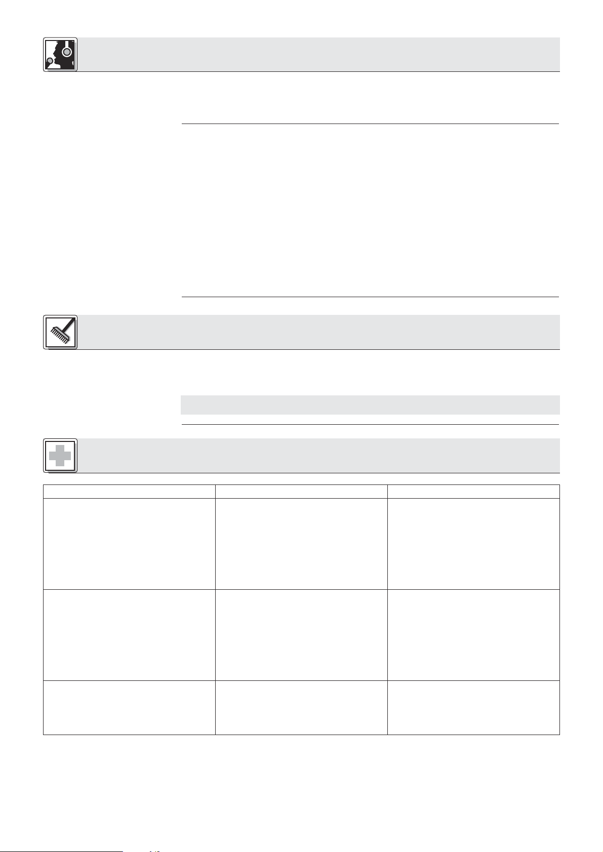
4 Operating Notes
3. To calm down a heated discussion, the chairperson can press and hold down the priority button to
mute all other microphones (except for those switched out of the priority bus). The microphones can
not be activated before the chairperson releases the priority button. In a system with several Base
Units, the priority key will mute only those microphones that are connected to the same Base Unit as the
Microphone Station on which the priority button was pressed.
4.8 Replacing Internal Fuses
Refer to fig. 5.
5 Cleaning
Important!
Each Microphone Station bus (LINE 1 to LINE 4) has its own T4A slow-blow fuse and the motherboard
uses a T1A slow-blow fuse.
• If the rear panel ERROR Σ LED on the Base Unit and the red ERROR LED in the front panel OUTPUT
CONTROL section illuminate, the motherboard fuse has blown.
• If the front panel ERROR LED, the rear panel ERROR Σ LED, and one of the ERROR LEDs next to a
LINE connector illuminate, the fuse on the respective Microphone Station bus has blown.
Replace the defective fuse:
1. Switch power to the Base Unit and the related power supplies OFF.
2. Remove the fixing screws of the Base Unit top panel.
3. Remove the top panel.
4. Remove the defective fuse ( ) from its holder.
5. Insert a new fuse of the same type ( : T4A slow-blow for LINE 1 through 4; : T1A slowblow for the motherboard).
6. Screw the top panel back on the Base Unit.
1. Switch power to the Base Unit off and disconnect the power supply/supplies from power.
2. Use a cloth slightly moistened (not wet!) with water to clean the surfaces of the Base Unit, power supplies, and Microphone Stations.
Never use caustic or scouring cleaners or cleaning agents containing alcohol or solvents since
these may damage the enamel or plastic parts.
6 Troubleshooting
Problem
No sound.
In Voice Activation mode, a single microphone
is talked into but all microphones come on.
The system works but some Microphone
Stations do not.
Possible Cause
1. Power supply/supplies not connected to
power.
2. Power supply/supplies not connected to
Base Unit(s).
3. Power supply/supplies and/or Base Unit(s)
are OFF.
4. MIC DELEGATES LEVEL control fully CCW.
5. One or more internal fuses on the Base
Unit have blown.
1. Gate threshold too low.
2. Volume level of Microphone Station loudspeakers is too high and mechanical noise
triggers gate.
1. Zero voltage at DC INPUT +1 or +2.
2. If you use two CS PS 20s, one may be
defective.
3. One of the internal fuses has blown (appropriate ERROR LEDs illuminated).
Remedy
1. Connect power supply/supplies to a
suitable power outlet.
2. Connect power supply/supplies to Base
Unit(s)
3. Switch power to Base Unit(s) and/or power
supply/supplies on.
4. Turn MIC DELEGATES LEVEL control up.
5. Replace fuse(s).
1. Set dip switch no. 1 on Microphone
Stations to "OFF" ("1").
2a.Turn down SPEAKERS OUT control on
Base Unit.
2b.Use external sound system instead of
built-in loudspeakers.
2c.Use headphones instead of built-in loud-
speakers.
2d.Deactivate Voice Activation.
1. Refer to section 3.3.
2. Replace defective power supply.
3. Replace fuse (refer to section 4.8).
20
Page 21
7 Speciications
7.1 CS 2BU Base Unit
Inputs
LINE 1-4
Connectors 4 x male 15-pin D-Sub HD
Nominal input level +10 dBu
Type electronically balanced
Max. input level for <1% THD +23 dBu
LINE INPUT
Connector 3-pin female XLR
Nominal input level ±0 dBu
Type transformer balanced
Input impedance at 1 kHz 30 kΩ
Max. input level for <1% THD +17 dBu
AUX IN
Connectors 2 x female RCA
Nominal input level -10 dBu
Type unbalanced
Input impedance at 1 kHz 33 kΩ
Max. input level for <1% THD +5 dBu
Outputs
REC OUT
Connectors 2 x female RCA
Nominal output level ±0 dBu
Max. output level at 1% THD 17 dBu
Audio bandwidth 15 Hz to 50 kHz
Min. load impedance 33 Ω
THD & N at 1 kHz 0.01%
S/N ratio 62 dB
LINE OUTPUT
Connector 3-pin male XLR
Nominal output level ±0 dBu
Max. output level at 1% THD +10 dBu
Audio bandwidth 20 Hz to 40 kHz
Min. load impedance 300 Ω
THD & N at 1 kHz 0.02%
S/N ratio 88 dB
Headphones
Connector 1/4" TRS jack
Nominal output level ±0 dBu
Max. output level at 1% THD +14 dBu
Min. load impedance 150 Ω
THD & N at 1 kHz 0.05%
S/N ratio 70 dB
EFFECT
Connector 1/4" TRS jack
Nominal level ±0 dBu
Input impedance <4.7 kΩ
Max. output level at 1% THD +14 dBu
Min. load impedance 220 Ω
System
Operating voltage 23 to 36 VDC
Current consumption at max. voltage 170 to 200 mA
Max. power requirement 7.2 watts
Size (LxWxH)
Shipping/net weight
Package contents
Order Numbers
CS 2 BU 6000H3400
Optional Accessories
CS PS 20 6000H3600
CS PS 100 6000H3601
CS MK AC-EU 6000H3602
CS MK AC-US 6000H3603
CS MC AC-UK 6000H3604
170 x 430 x 40 mm (6.7 x 19 x 1.6 in.)
3.2 kg (7.1 lbs.) / 2.5 kg (6.2 lbs.)
Base Unit without power supply
Type transformer balanced, floating
Nominal level +10 dBu
Audio bandwidth 55 Hz to 35 kHz
S/N ratio 81 dB
System compatibility compatible to CS 1
THD & N at 1 kHz 0.25%
Equivalent input noise, noise gate on,
22 Hz to 22 kHz -105 dBu
Headphones and Loudspeakers
Connectors 2 x TS mini jack
Output power for <1% THD 0.48 watts (loudspeakers)
Audio bandwidth 30 Hz to 45 kHz
S/N ratio 85 dB
THD & N at 1 kHz 0.25%
Equivalent input noise, noise gate on,
22 Hz to 22 kHz -105 dBu
Digital pot attenuation
System
Adjustable functions Voice Activation sensitivity
Voice Activation hold time
Mic Automute
NOM Limitation
Voice Activation on/off
Priority on/off
Compression on/off
Digipot reset on power-up/last setting
memory
Compression ratio
Color AKG Blue Line gray / matte black
Package contents Microphone Station without cable and
microphone
Order Numbers
CS 2 CU 2770Z0001
CS 2 DU 2770Z0002
CS 2 CU fix 2770Z0003
CS 2 DU fix 2770Z0004
Optional Accessories
CS MK 1.25 fm 1.25-m (4-ft.) connecting cable 2770Z0011
CS MK 2.5 fm 2.5-m (8-ft.) connecting cable 2770Z0012
CS MK 5 fm 5-m (16-ft.) connecting cable 2770Z0013
CS MK 10 fm 10-m (33 ft.) connecting cable 2770Z0014
CS MK 20 fm 20-m (66-ft.) connecting cable 2770Z0015
CK 31 Discreet Acoustics microphone capsule 2765Z0020
CK 32 Discreet Acoustics microphone capsule 2765Z0021
CK 33 Discreet Acoustics microphone capsule 2765Z0022
CK 47 Discreet Acoustics microphone capsule 2765Z0023
CK 80 Discreet Acoustics microphone capsule 2765Z0024
GN 30 CS gooseneck (approx. 30 cm/12 in.) 2765Z0027
GN 30 CS gooseneck (approx. 50 cm/20 in.) 2765Z0028
CS MK 1/2 100-m (330-ft.) cable 9.5 mm (0.37 in.) in diameter
for permanent installation 6000H3612
CS MK 100 oc/mob 100-m (330-ft.) cable 7 mm (0.27 in.) in diameter
for mobile installation 6000H3611
CS CON fm/fi female D-Sub connector
for permanent installation 6000H3620
CS CON m/fi as CS CON fm/fi, male 6000H3621
CS CON fm/mob female D-Sub for mobile use 6000H3622
CS CON m/mob male D-Sub for mobile use 6000H3623
CS CON floor/m/fi male floor-mount D-Sub 6000H3624
CS CON split2/m/mob male 2-way D-Sub 6000H3625
CS CON split4/m/mob male 4-way D-Sub
K 10 conference headphones 2246Z0013
K 11 single earphone 2724Z0011
32 increments from 0 to –82 dB
7.2 CS 2 DU / CS 2 CU Microphone Stations
Compatible microphones GN 30 CS or GN 50 CS with
Input
Type
Impedance 1.5 kΩ
Supply voltage for microphone capsule
Outputs
Line
Connectors 2 x male 15-pin D-Sub HD
CK 31, CK 32, CK 33, CK 47,
or CK 80 only
balanced, with DC supply voltage
5.5 VDC
21
Page 22

Table des matières
1 Sécurité et environnement . . . . . . . . . . . . . . . . . . . . . . . . . . . . . . . . . . . . . . . . . . . . . . . 22
1.1 Sécurité . . . . . . . . . . . . . . . . . . . . . . . . . . . . . . . . . . . . . . . . . . . . . . . . . . . . . . . . . . 22
1.2 Environnement . . . . . . . . . . . . . . . . . . . . . . . . . . . . . . . . . . . . . . . . . . . . . . . . . . . . . 23
2 Description. . . . . . . . . . . . . . . . . . . . . . . . . . . . . . . . . . . . . . . . . . . . . . . . . . . . . . . . . . . . 23
2.1 Introduction . . . . . . . . . . . . . . . . . . . . . . . . . . . . . . . . . . . . . . . . . . . . . . . . . . . . . . . 23
2.2 Fournitures d’origine. . . . . . . . . . . . . . . . . . . . . . . . . . . . . . . . . . . . . . . . . . . . . . . . . 23
2.3 Accessoires optionnels. . . . . . . . . . . . . . . . . . . . . . . . . . . . . . . . . . . . . . . . . . . . . . . 23
2.4 Unité centrale CS 2 BU . . . . . . . . . . . . . . . . . . . . . . . . . . . . . . . . . . . . . . . . . . . . . . 23
2.4.1 Façade . . . . . . . . . . . . . . . . . . . . . . . . . . . . . . . . . . . . . . . . . . . . . . . . . . . . . . 23
2.4.2 Face arrière . . . . . . . . . . . . . . . . . . . . . . . . . . . . . . . . . . . . . . . . . . . . . . . . . . . 24
2.5 Postes micros . . . . . . . . . . . . . . . . . . . . . . . . . . . . . . . . . . . . . . . . . . . . . . . . . . . . . 25
2.5.1 Face supérieure. . . . . . . . . . . . . . . . . . . . . . . . . . . . . . . . . . . . . . . . . . . . . . . . 25
2.5.2 Face inférieure. . . . . . . . . . . . . . . . . . . . . . . . . . . . . . . . . . . . . . . . . . . . . . . . . 25
Diagramme . . . . . . . . . . . . . . . . . . . . . . . . . . . . . . . . . . . . . . . . . . . . . . . . . . . . . . . . . . . 63
3 Mise en service . . . . . . . . . . . . . . . . . . . . . . . . . . . . . . . . . . . . . . . . . . . . . . . . . . . . . . . . 25
3.1 Unité(s) centrale(s) . . . . . . . . . . . . . . . . . . . . . . . . . . . . . . . . . . . . . . . . . . . . . . . . . . 25
3.1.1 Configuration de l’unité/des unités centrale(s) . . . . . . . . . . . . . . . . . . . . . . . . . 25
3.1.2 Cascade de plusieurs unités centrale(s). . . . . . . . . . . . . . . . . . . . . . . . . . . . . . 26
3.1.3 Raccordement des éléments de commande et d’indication à distance . . . . . . 26
3.1.4 Raccordement d’un égaliseur ou d’un suppresseur de larsen. . . . . . . . . . . . . . 26
3.1.5 Raccordement d’autres appareils externes . . . . . . . . . . . . . . . . . . . . . . . . . . . 26
3.2 Postes micros . . . . . . . . . . . . . . . . . . . . . . . . . . . . . . . . . . . . . . . . . . . . . . . . . . . . . 26
3.2.1 Configuration des postes micros . . . . . . . . . . . . . . . . . . . . . . . . . . . . . . . . . . . 26
3.2.2 Montage des postes micros "CS 2 DU fix"/"CS 2 CU fix" . . . . . . . . . . . . . . . . 27
3.2.3 Raccordement des postes micros . . . . . . . . . . . . . . . . . . . . . . . . . . . . . . . . . . 27
3.2.4 Raccordement des microphones . . . . . . . . . . . . . . . . . . . . . . . . . . . . . . . . . . . 28
3.3 Branchement sur le secteur . . . . . . . . . . . . . . . . . . . . . . . . . . . . . . . . . . . . . . . . . . . 28
4 Instructions pour l’utilisation. . . . . . . . . . . . . . . . . . . . . . . . . . . . . . . . . . . . . . . . . . . . . . 29
4.1 Mise sous tension . . . . . . . . . . . . . . . . . . . . . . . . . . . . . . . . . . . . . . . . . . . . . . . . . . 29
4.2 Mise hors tension. . . . . . . . . . . . . . . . . . . . . . . . . . . . . . . . . . . . . . . . . . . . . . . . . . . 29
4.3 Réglage de la limitation du nombre des participants. . . . . . . . . . . . . . . . . . . . . . . . . 29
4.4 Pour activer et désactiver les micros (Voice Activation et Automute). . . . . . . . . . . . . 29
4.5 Réglage des haut-parleurs . . . . . . . . . . . . . . . . . . . . . . . . . . . . . . . . . . . . . . . . . . . . 29
4.6 Réglage du zoom vocal . . . . . . . . . . . . . . . . . . . . . . . . . . . . . . . . . . . . . . . . . . . . . . 29
4.7 Remarques concernant l’utilisation des postes micros . . . . . . . . . . . . . . . . . . . . . . . 29
4.8 Remplacement des fusibles internes de l’unité centrale . . . . . . . . . . . . . . . . . . . . . . 30
Page
5 Nettoyage. . . . . . . . . . . . . . . . . . . . . . . . . . . . . . . . . . . . . . . . . . . . . . . . . . . . . . . . . . . . . 30
6 Dépannage . . . . . . . . . . . . . . . . . . . . . . . . . . . . . . . . . . . . . . . . . . . . . . . . . . . . . . . . . . . . 30
7 Caractéristiques techniques . . . . . . . . . . . . . . . . . . . . . . . . . . . . . . . . . . . . . . . . . . . . . . 31
7.1 Unité centrale CS 2 BU . . . . . . . . . . . . . . . . . . . . . . . . . . . . . . . . . . . . . . . . . . . . . . 31
7.2 Postes micros CS 2 DU / CS 2 CU. . . . . . . . . . . . . . . . . . . . . . . . . . . . . . . . . . . . . . 31
1 Sécurité et environnement
1.1 Sécurité
1. Faites attention de ne pas renverser de liquide sur l’appareil et à ce que rien ne tombe à l’intérieur par
les fentes d’aération.
2. Cet appareil ne doit en aucun cas être utilisé dans un local humide.
3. Cet appareil ne peut être ouvert, entretenu et réparé que par le personnel technique autorisé. On ne
trouve à l’intérieur du boîtier aucun élément pouvant être entretenu, réparé ou remplacé par un profane.
4. Avant de mettre l’appareil en service, vérifiez si la tension de service indiquée sur l’adaptateur secteur
fourni correspond bien à la tension secteur sur le lieu d’utilisation.
5. Cet appareil devra être utilisé exclusivement avec le bloc secteur CS PS 20 ou CS PS 100 fourni, sous
une tension secondaire de 23 à 36 V c.c. ; tout autre type de courant ou de tension risque de provoquer de graves dégâts sur l’appareil !
6. S’il arrivait qu’un objet quelconque ou du liquide pénètre à l’intérieur de l’appareil, mettez immédiatement la chaîne hors service. Débranchez aussitôt l’adaptateur secteur et faites réviser l’appareil par
notre service après-vente.
7. Lorsque vous avez l’intention de rester quelque temps sans utiliser l’appareil, débranchez l’adaptateur secteur. Tant que l’adaptateur est branché sur la prise secteur, l’appareil n’est pas entièrement
coupé du secteur lorsque vous le mettez hors tension.
8. Ne placez jamais l’appareil à proximité d’une source de chaleur (radiateur, tuyaux de chauffage, amplificateurs, etc.) ni à un endroit où il risque d’être exposé directement au soleil, à une atmosphère poussiéreuse, à l’humidité, à la pluie, aux vibrations ou aux secousses.
9. Pour éviter les parasites et les interférences, posez tous les fils, en particulier ceux des entrées micro,
séparément des câbles de puissance et des lignes de secteur. En cas de pose dans un puits ou une
conduite pour câbles, les câbles de transmission devront toujours être posés dans une conduite
séparée.
22
Page 23

1 Sécurité et environnement
10.Pour nettoyer l’appareil, utilisez un chiffon légèrement humide, jamais un chiffon mouillé. N’oubliez
surtout pas de débrancher auparavant l’adaptateur secteur ! N’utilisez jamais de produits de nettoyage mordants ou abrasifs, non plus que des produits contenant de l’alcool ou un solvant qui risqueraient d’abîmer la laque et les éléments en plastique.
1. Le bloc secteur CS PS 20 consomme toujours un peu de courant, même lorsque l’appareil n’est pas
sous tension. Pour économiser du courant, il est donc conseillé de débrancher le câble secteur lorsque vous savez que l’appareil restera un certain temps sans être utilisé.
2. Si vous mettez l'appareil à la ferraille, enlevez les piles ou les accus, séparez le boîtier, l'électronique
et les câbles et éliminez les différents éléments conformément aux règlements en vigueur.
Nous vous remercions d’avoir choisi un produit AKG. Pour profiter au maximum des avantages que vous
offre le CS 2, lisez très attentivement ce mode d’emploi avant la mise en service de l’appareil.
Conservez soigneusement le mode d’emploi pour pouvoir le consulter lorsque vous vous posez des questions. Nous vous souhaitons beaucoup de succès.
Le système conférencier CS 2 d’AKG offre une remarquable qualité audio ; grâce à la technologie monocâble, son installation est simple et rapide. Sa construction modulaire vous permet de réaliser facilement
un système répondant aux besoins de vos clients. Vous disposez à cet effet de différents câbles de raccordement, de postes micros pour installation sur table ou montage fixe intégré à la table ainsi que de
divers blocs secteurs, cols de cygne et capsules de microphone.
L’unité centrale CS 2 BU alimente et commande jusqu’à 200 postes micro. Les installations comptant au
maximum 40 postes micro, nécessitent un bloc secteur CS PS 20, les installations comptant au maximum 200 postes micro, un bloc secteur CS PS 100.
Le poste micro du président de séance CS 2 CU, avec touche de priorité, de même que le poste délégué CS 2 DU possèdent un raccord fileté breveté pour col-de-cygne GN 30 CS (30 cm) ou GN 50 CS
(50 cm). Vous pouvez monter sur le col-de-cygne une des 5 capsules de la gamme Discreet Acoustics
d’AKG.
Contrôlez si vous avez bien reçu les 7 éléments figurant sur la liste ci-dessous, avec pour chacun la
quantité commandée. Si ce n’est pas le cas, veuillez le signaler à votre distributeur AKG.
1.2 Environnement
2 Description
2.1 Introduction
2.2 Fournitures d’origine
1. Unité centrale CS 2 BU
2. Bloc secteur : CS PS 20 ou CS PS 100
3. Câbles secteur : CS MK AC-EU, CS MK AC-US ou CS MK AC-UK
4. Postes micro : CS 2 DU, CS 2 DU fixe, CS 2 CU ou CS 2 CU fixe
5. Câbles de raccordement : CS MK 1.25 fm, CS MK 2.5 fm, CS MK 5 fm, CS MK 10 fm ou CS MK 20 fm
6. Col-de-cygne : GN 30 CS ou GN 50 CS
7. Capsules de micros : CK 31, CK 32, CK 33, CK 80 ou CK 47
Vous trouverez une liste des accessoires optionnels pour le système conférencier CS 2 ainsi que les
références pour la commande aux points 7.1 et 7.2, page 31.
MIC DELEGATES LEVEL: Bouton de réglage de niveau pour tous les microphones.
LINE LEVEL: Bouton de réglage de niveau de l’entrée symétrique pour les appareils audio externes (LINE
INPUT).
AUX LEVEL: Bouton de réglage de niveau de l’entrée AUX asymétrique.
ACTIVE MICS: Lorsque le micro d’un des postes micros est ouvert, une des LED bleues 1 à 4 s’allume.
Lorsque 5 micros ou plus sont ouverts simultanément, la LED 5 s’allume.
NOM LIMITATION: Le bouton NUMBER OF OPEN MICROPHONES s’utilise pour limiter le nombre de
micros pouvant être ouverts simultanément. La LED rouge LIMIT s’allume dès que le nombre de
micros ouverts atteint la limite imposée.
OPERATION MODE: Lorsque vous appuyez sur cette touche, l’unité centrale se trouve en mode Voice
Activation. Dès que quelqu’un parle dans un micro celui-ci est mis en service. Lorsqu’on utilise ce
mode de fonctionnement la LED rouge VOICE ACTIVATION s’allume.
Lorsque cette touche n’est pas enfoncée, on met un micro en service en appuyant sur la touche rouge
du poste micro correspondant. Dans ce cas, la LED VOICE ACTIVATION reste éteinte.
2.3 Accessoires optionnels
2.4 Unité centrale CS 2 BU
2.4.1 Façade
Voir Fig. 1.
ERROR: Lorsque cette LED rouge est allumée elle indique qu’un des fusibles des raccordements de
postes micros LINE 1 à LINE 4 ou le fusible de la carte-mère est grillé. Voir aussi au point 4.8.
SPEAKERS OUT: Bouton de réglage du volume maximum des haut-parleurs incorporés et du niveau
maximum du casque pour TOUS les postes micros.
23
Page 24

2 Description
BALANCED OUT: Bouton de réglage du niveau de la sortie symétrique ligne (LINE OUTPUT).
HEADPHONES OUT: Bouton de réglage du volume de la sortie casque ".
": Embase jack de 6,35 mm pour le raccordement d’un casque.
POWER: Interrupteur à bascule pour mettre l’unité centrale sous tension ("I") ou hors tension ("0").
ON: Lorsque cette LED verte est allumée l’unité centrale est sous tension.
Remarque :
2.4.2 Face arrière
Voir Fig. 2.
Remarque :
La LED ON ne s’allume qu’au bout de 2 secondes après la mise sous tension. Cet intervalle est nécessaire pour la stabilisation interne de la tension d’alimentation.
EXPANSION IN/ OUT: Ces deux mini-connecteurs DIN 8 points (dits aussi connecteurs Hosiden ou S-
VHS) vous permettent d’interconnecter plusieurs unités centrales lorsque vous devez réaliser un
système comptant plus de 200 postes micros. Pour relier les unités centrales deux par deux vous
avez besoin d’un câble d’extension IC AS 8 d’AKG (optionnel) et du fil de au moins 0.5 mm2pour relier
les bones 0V sur les deux unités centrales.
L’unité centrale dont un seul câble est branché sur le connecteur EXPANSION OUT est identifié automatiquement comme "maître" et son interrupteur POWER met également toutes les unités centrales
"esclaves" sous tension. Les signaux audio de toutes les unités centrales sont additionnés et appliqués aux connecteurs LINE OUTPUT de toutes les unités centrales. Les signaux de commande pour
les fonctions limitation participants, priorité etc. ne sont pas additionnés. Chaque unité centrale commande, pourtant, seulement les postes micro reliés à cette unité centrale.
Vous pouvez également raccorder aux connecteurs EXPANSION un interrupteur marche/arrêt commandé à distance et/ou tout autre élément de commande ou témoin. Vous trouvez desinformations
additionnelles sur l’utilisation des connecteur EXPANSION au point 3.1.3.
LINE OUTPUT: Ce connecteur XLR 3 points symétrisé par trafo (broche 2 = point chaud) fournit le sig-
nal de sortie master de tous les canaux d’entrée. Le niveau nominal est de 0 dBu. Le niveau de sortie se règle à l’aide du bouton BALANCED OUT en façade.
REC OUT L/R: On dispose sur ces deux connecteurs Cinch du même signal mono asymétrique pour un
magnétophone ou un enregistreur à cassettes. Les connecteurs REC OUT délivrent le signal master
de sortie de tous les canaux d’entrée.
Le potentiomètre trimmer rouge à gauche des connecteurs REC OUT vous permet de régler le niveau
de sortie sur les deux connecteurs. La position des boutons de la section OUTPUT CONTROL, en
façade, est sans influence sur ce réglage.
AUX IN L/R: Ces deux connecteurs Cinch permettent de raccorder un appareil audio tel qu’un lecteur
de CD pour les annonces importantes.
Les signaux d’entrée stéréo s’additionnent pour donner un signal mono.
Un signal arrivant aux connecteurs AUX IN ne met PAS les microphones sur muet.
Tableau 1: Brochage des connec-
teurs 15 points Sub-D et code
couleur du câble de raccordement
EFFECT: Vous pouvez insérer dans ce jack stéréo de 6,35 mm un égaliseur ou un suppresseur de larsen
pour réduire le risque d’accrochages dans les salles présentant des problèmes d’acoustique.
Brochage du jack :
Pointe = entrée (Return)
Anneau = sortie (Send)
Tige = masse
LINE INPUT: Vous pouvez raccorder sur ce connecteur XLR symétrique 3 points (broche 2 = point chaud)
une source de signaux de niveau de ligne symétrisée par trafo, p.ex. un Codec vidéo ou un système
de microphones sans fil.
DELEGATE UNITS/ LINE 1-4: Vous pouvez raccorder jusqu’à 50 postes micro sur chacun des connec-
teurs Sub-D 15 points LINE 1 à LINE 4. Le type et le nombre des blocs secteur dont vous avez besoin
dépend du nombre total de postes micro ; la longueur totale des câbles de branchement par connecteur ne doit pas dépasser 100 m.
La LED rouge ERROR à côté de chaque connecteur LINE s’allume, lorsque le fusible interne (T4A à
action retardée) du port correspondant est grillé. Voir aussi au point 4.8.
Broche N° Couleur Fonction
1rose Tension d’alimentation 23 ... 36 V
2rouge Tension d’alimentation 23 ... 36 V
3 gris Masse 0V
4 bleu Masse 0V
5 blindage externe Blindage
6 vert Limitation participants
7 jaune Identification des micros actifs
8 blindage vert/jaune Identification des micros actifs
9 blanc/vert Priorité
10 marron/vert Voice Activation (déclenchement à la voix)
11 blanc Signal vocal +
12 marron Signal vocal 13 blindage blanc/marron Blindage
14 noir Haut-parleur +
15 violet Haut-parleur –
24
ERROR Σ:Cette LED rouge s’allume toujours en même temps que la LED ERROR en façade. Si ces deux
LED sont les seules allumées alors que toutes les LED ERROR à côté des connecteurs LINE-B sont
éteintes, le fusible (T1A à action retardée) de la carte-mère est grillé. Voir aussi au point 4.8.
Page 25

GND/0V: Ce strap constitue une liaison à la masse avec le rack. Vous pouvez l’enlever pour supprimer
les boucles de masse.
DC INPUT: Connecteur Phoenix 4 points pour un ou deux blocs secteurs suivant le nombre de postes
micro raccordés.
Les bornes 0V1 et +1 alimentent les postes micro connectés à LINE 1 et LINE 2, les bornes 0V2 et +2
alimentent les postes micro connectés à LINE 3 et LINE 4.
2 Description
Le poste micro délégué CS 2 DU et le poste micro président de séance CS 2 CU présentent tous les mêmes
fonctions et les mêmes éléments de commande, à cette seule différence que le poste micro président de
séance possède en outre une touche de priorité qui permet de mettre tous les autres micros sur muet.
Entrée micro : mini-jack de 3,5 mm plaqué or présentant un raccord fileté pour col-de-cygne GN 30
CS ou GN 50 CS avec capsule de microphone Discreet Acoustics.
+/-: Ces deux touches permettent d’incrémenter ("+") ou décrémenter ("-") sur 31 niveaux le volume
des deux haut-parleurs incorporés. Le dernier niveau "-" (-81 dB) correspond à "muet".
Pour éviter les rétroactions, les haut-parleurs incorporés sont automatiquement mis sur muet dès que
le micro est en service.
": Vous pouvez brancher un casque sur chacun des deux mini-jacks de 3,5 mm.
Les haut-parleurs incorporés sont automatiquement mis sur muet dès que vous branchez un casque.
Néanmoins, le signal du casque n’est PAS mis sur muet lorsqu’on ouvre le micro (il n’y a normalement
pas de risque d’accrochage entre casque et micro).
Bouton de parole avec LED témoin : Le bouton de parole rouge sert à ouvrir et fermer le micro. Si
la limitation du nombre de participants est activée, le micro ne se met en service que lorsque le nombre des micros ouverts est inférieur au nombre maximum choisi. La LED de contrôle reste allumée tant
que le micro est ouvert.
Touche de priorité (CS 2 CU seulement) : En appuyant sur la touche de priorité noire et en la main-
tenant enfoncée, le/la président(e) de séance peut mettre tous les micros ouverts sur muet et ouvrir
le micro du poste président de séance. Dès qu’il/elle relâche la touche de priorité, le micro du poste
président de séance est remis sur muet et les autres micros peuvent de nouveau être activés.
Connecteurs : Le poste micro comporte deux connecteurs 15 points Sub-D (mâles) pour le raccor-
dement à l’unité centrale et/ou à d’autres postes micro.
Commutateurs DIP 1 à 8: Les commutateurs DIP recouverts par un panneau amovible correspon-
dent aux fonctions suivantes :
2.5 Postes micro
2.5.1 Face supérieure
Voir Fig. 3 (CS 2 CU).
2.5.2 Face inférieure
Voir Fig. 4.
N° du commutateur Fonction OFF (1-8) ON
Position du commutateur
1 Seuil d’intervention du Noise Gate haut bas
2Temps de maintien 12 s 6 s
3 Mise automatique sur muet active inactive
4 Limitation du nombre de participants non oui
5 Déclenchement à la voix actif inactif
6 Mise sur muet par le président non oui
7 Compression actif inactif
8 Mémorisation niveau haut-parleur active inactive
Potentiomètre A: Permet de varier la sensibilité de l’entrée.
Potentiomètre B: Permet de varier le rapport de compression de la fonction zoom vocal.
Potentiomètre P3: Règle le niveau de sortie du poste micro. Le niveau de sortie a été réglé en usine sur
la valeur optimale pour l’unité centrale CS 2 BU. Ne modifiez en aucun cas le réglage de P3 sous
peine de perturber le fonctionnement de l’installation.
3 Mise en service
Configurez l’unité/ les unité(s) centrale(s) et les postes micro, montez tous les appareils 19"
(unité(s) centrale(s)) CS 2 BU, bloc(s) secteur CS PS 100) dans votre rack et effectuez tous les raccordements audio et extensions avant de brancher l’installation sur le secteur.
L’unité centrale CS 2 BU comporte un égaliseur interne (atténuation du grâve de 6 dB à 500 Hz) et un
point d’insertion pour un égaliseur externe ou un suppresseur de larsen. Départ usine, l’égaliseur interne
agit sur les haut-parleurs incorporés de tous les postes micro raccordés et le point d’insertion est situé
en amont de la sortie ligne (LINE OUTPUT).
Tableau 2: Fonctions des commutateurs DIP
Important !
3.1 Unité(s) centrale(s)
3.1.1 Configuration de
l’unité/ des unités centrale(s)
25
Page 26

3 Mise en service
Trois straps à l’intérieur de l’unité centrale vous permettent de modifier cette configuration :
1. Dévissez les vis de fixation du panneau supérieur du boîtier de l’unité centrale.
Voir Fig. 5.
2. Déposez le panneau.
3. Mettez les straps selon la configuration souhaitée :
Tableau 3: Straps internes
Remarque :
3.1.2 Cascade de plusieurs
unités centrales
Voir Fig. 6
3.1.3 Raccordement des
éléments de commande et
d’indication à distance.
Voir Fig. 7.
Strap Position agit sur : agit sur :
EFFECT EQ interne
X9 1-2 (réglage usine) LINE OUTPUT --
2-3 -- --
X10 1-2 haut-parleurs --
incorporés des
postes micro
2-3 (réglage usine) -- --
X7 1-2 (réglage usine) -- haut-parleurs
incorporés des
postes micro
2-3 -- -X10 1-2 haut-parleurs incorporés des postes micro
X7 1-2 (EFFECT et EQ interne en série)
Lorsque X10 et X7 se trouvent l’un et l’autre en position 1-2 l’appareil externe et l’égaliseur interne
sont couplés en série. Ils agissent l’un et l’autre sur les haut-parleurs incorporés.
4. Remontez le panneau sur le boîtier et fixez-le à l’aide des vis.
1. Raccordez à l’aide d’un câble d’extension optionnel IC AS 8 le connecteur EXPANSION OUT de la première unité centrale ("maître") au connecteur EXPANSION IN de la deuxième unité centrale ("esclave").
L’unité centrale sur laquelle seul le connecteur EXPANSION OUT est raccordé à un second appareil
est automatiquement identifié comme "maître" dont l’interrupteur principal met aussi en service/hors
service toutes les unités centrales "esclaves".
2. A l’aide d’un autre câble d’extension optionnel IC AS 8, raccordez le connecteur EXPANSION OUT de
la deuxième unité centrale au connecteur EXPANSION IN de la troisième unité centrale, et ainsi de
suite.
3. Reliez les bornes 0V de toutes les unités centrales en série avec du fil d’au moins 0,5 mm2.
Vous pouvez aussi utiliser le connecteur EXPANSION IN ou EXPANSION OUT pour raccorder à l’unité
centrale un interrupteur marche/arrrêt ainsi que d’autres éléments de commande et d’indication à
distance. Sur les unités centrales cascadées, seul le connecteur EXPANSION IN de l’unité centrale "maître" peut être utilisé à cet effet.
Important !
3.1.4 Raccordement d’un
égaliseur ou d’un suppresseur
de larsen
3.1.5 Raccordement d’autres
appareils externes
3.2 Postes micro
3.2.1 Configuration des
postes micro
Voir Fig. 8 et tableau 2,
page 25.
Brochage des connecteurs EXPANSION :
Broche 2 : Interrupteur marche/arrêt commandé à distance. L’unité centrale est sous tension tant
que la broche 2 est reliée à DC INPUT 0V1 ou 0V2.
Broches 3+4 : ERROR. Lorsqu’un fusible interne est grillé les broches 3 et 4 sont court-circuitées.
Raccordez votre indicateur ERROR aux broches 3+4.
Broches 7+8 : PRIORITY. On dispose à la broche 7 d’une tension d’alimentation de +23 à +36 V c.c.
(suivant le bloc secteur) pouvant être utilisée pour une lampe externe, un relais, etc. (Sur
EXPANSION OUT seulement ! Sur EXPANSION IN la broche 7 est libre.) Tant que la touche de
priorité d’un poste président de séance est enfoncée, la broche 8 est à 0V.
Raccordez votre relais, etc., aux broches 7+8.
Les autres broches servent exclusivement à cascader plusieurs unités centrales. Ne raccordez
jamais un appareil externe à ces broches sous peine de détérioration de l’unité centrale.
A l’aide d’un câble Y (non fourni) vous pouvez brancher sur le connecteur d’insertion EFFECT au dos de
l’unité centrale un égalisateur ou un suppresseur de larsen.
Brochage du connecteur d’insertion EFFECT :
Pointe : Return (retour de la sortie de l’égaliseur)
Anneau : Send (sortie vers l’entrée de l’égaliseur)
Tige : Masse
Raccordez vos appareils externes aux entrées et sorties correspondantes.
Exemples : Installation de sonorisation externe à LINE OUTPUT; appareil d’enregistrement à REC OUT;
lecteur de CD à AUX IN; système de microphones HF (p.ex. WMS 81 ou WMS 40 d’AKG) à LINE INPUT.
1. Enlevez le panneau recouvrant les commutateurs DIP.
2. Réglez les commutateurs DIP 1 à 8 en fonction de la conception de votre système :
• Le commutateur DIP N° 1 règle le seuil d’intervention du Noise Gate. Pour la position "OFF" le seuil
d’intervention est élevé et le microphone ne se met en service que si le micro est très près des lèvres
du locuteur. Dès que le micro est ouvert, le seuil d’intervention est automatiquement réduit de 6 dB
pour éviter la coupure du micro lorsque le locuteur baisse la voix ou s’écarte du micro.
26
Page 27

3 Mise en service
En position "ON" le seuil d’intervention est inférieur de 6 dB à celui de la position " OFF". Là encore,
le seuil d’intervention est de nouveau réduit automatiquement dès que le micro est ouvert.
• Le commutateur DIP N° 2 commute le temps pendant lequel le microphone reste ouvert à partir de
la fin d’une intervention sur 12 secondes ("OFF") ou 6 secondes ("ON").
• Le commutateur DIP N° 3 active ou désactive la mise automatique du microphone sur muet. En
position "OFF" le microphone est automatiquement coupé lorsque le délai choisi à l’aide du commutateur DIP N° 2 est écoulé.
En position "ON" le locuteur doit appuyer lui-même sur la touche de parole pour couper le micro.
• Le commutateur DIP N° 4 s’utilise lorsqu’on veut exclure le poste micro de la limitation du nombre
de participants. Ce sera principalement le cas pour le bus du poste micro du président de séance. En
position "OFF", le participant peut mettre le micro en service lorsqu’il le souhaite, indépendamment
du nombre de micros déjà ouverts.
En position "ON", le microphone ne peut être activé que si le nombre des micros ouverts est inférieur
à celui prévu sur l’unité centrale.
• Le commutateur DIP N° 5 permet de passer du mode manuel en mode de déclenchement à la voix
(Voice Activation) et inversement. Lorsque le commutateur est sur "OFF" le locuteur ne peut ouvrir ou
fermer le micro qu’en appuyant sur la touche de parole.
En position "ON", le locuteur peut également utiliser la touche de parole. Lorsque l’unité centrale est
en mode de déclenchement à la voix le micro se met automatiquement en service dès que l’utilisateur parle.
• Le commutateur DIP N° 6 vous permet d’exclure le poste micro de la mise sur muet par action sur
la touche de priorité d’un poste micro de président de séance. Sur tous les postes micro importants
(président de séance, vice-président, délégués importants) mettez le commutateur DIP N° 6 sur "OFF"
pour que ces micros restent ouverts même si le président de séance appuie sur la touche de priorité.
Lorsque le commutateur est sur " ON" le micro est mis sur muet dès que le président de séance appuie sur la touche de priorité.
• Le commutateur DIP N° 7 active ou désactive la fonction de zoom vocal. En position "OFF" le ren-
forcement du poste micro est automatiquement augmenté lorsque le locuteur baisse la voix tandis
que le signal est comprimé, voire limité, dès que le locuteur parle très fort ou trop près du micro.
En position "ON", le renforcement du poste micro reste constant.
Voir Fig. 8.
• Interrupteur DIP N° 8: lorsque le commutateur est sur "OFF" le dernier réglage de volume choisi pour
les haut-parleurs incorporés et les sorties casque est mémorisé ; ce réglage est conservé même après
coupure de l’installation.
En position "ON", le volume des haut-parleurs incorporés et des sorties casque est mis automatiquement sur maximum lors de la mise sous tension du système.
Le potentiomètre P3 à côté des interrupteurs DIP règle le niveau de sortie du poste micro. Le
niveau de sortie a été réglé en usine sur une valeur adaptée de façon optimale à l’unité centrale CS 2 BU. Faites donc bien attention de ne pas modifier le réglage de P3 ; une erreur de réglage perturberait le fonctionnement de l’installation.
3. Remettez le panneau recouvrant les interrupteurs DIP.
1. Découpez une ouverture dans le plateau de la table en utilisant le patron de la Fig. 13.
2. Insérez le poste micro dans cette ouverture et fixez-le par 4 vis appropriées (ne sont pas fournies).
Les 4 types de postes micro ont les même connecteurs pour le câble de raccordement CS MK:
Broche N° Couleur Fonction
1rose Tension d’alimentation 23 ... 36 V
2rouge Tension d’alimentation 23 ... 36 V
3 gris Masse 0V
4 bleu Masse 0V
5 blindage externe Blindage
6 vert Limitation participants
7 jaune Identification des micros actifs
8 blindage vert/jaune Identification des micros actifs
9 blanc/vert Priorité
10 marron/vert Voice Activation (déclenchement à la voix)
11 blanc Signal vocal +
12 marron Signal vocal 13 blindage blanc/marron Blindage
14 noir Haut-parleur +
15 violet Haut-parleur –
Important !
3.2.2 Montage des postes
micros "CS 2 DU fix"/
"CS 2 CU fix"
Voir Fig. 13.
3.2.3 Raccordement des
postes micro
Le nombre maximum de postes micro que vous pouvez brancher sur chaque connecteur DELEGATE
UNITS LINE dépend des blocs secteurs raccordés à l’unité centrale :
27
Page 28

3 Mise en service
Tableau 4: Nombre maximum de
postes micro et répartition recom-
mandée de ces postes en fonction
des blocs secteurs utilisés
Important !
3.2.4 Raccordement des
microphones
Remarque :
Voir Fig. 9.
3.3 Branchement sur le secteur
Important !
Voir Fig. 10.
Blocs secteurs au total LINE 1 LINE 2 LINE 3 LINE 4
Nombre de postes micro (possible) / optimal
1 x CS PS 20 40 (40) / 10 (0) / 10 (0) / 10 (0) / 10
2 x CS PS 20 80 (50) / 20 (30) / 20 (0) / 20 (0) / 20
1 x CS PS 100 200 50 50 50 50
1. Raccordez à l’aide d’un câble CS MK de la longueur voulue le connecteur DELEGATE UNITS LINE 1
sur l’unité centrale à l’un des deux connecteurs sur le premier poste micro.
2. Raccordez l’autre connecteur du premier poste micro à l’un des connecteurs du poste micro suivant,
et ainsi de suite.
Si vous raccordez le nombre maximum de postes micro, répartissez ceux-ci sur les connecteurs LINE 1 à 4 conformément aux indications du tableau 4. Faites en sorte que la longueur
totale du câble, de l’unité centrale au dernier poste micro, ne dépasse pas 100 m. Ce n’est
qu’ainsi que vous pouvez avoir l’assurance d’une alimentation suffisante pour tous les postes
micro (au minimum 21 V c.c.).
1. Choisissez pour chaque poste micro le col de cygne et la capsule de microphone convenables. Pour
plus de détails, veuillez consulter le mode d’emploi de la gamme Discreet Acoustics Modular.
Vous pouvez aussi utiliser tous les postes micro en tant que simples postes d’écoute sans microphone, p.ex. pour les secrétaires ou sténodactylos.
2. Vissez la capsule de microphone sur le col-de-cygne.
3. Vissez le col-de-cygne dans l’embase microphone du poste micro.
Vérifiez si la tension secteur indiquée sur vos blocs secteur est bien identique à la tension du secteur sur le lieu d’utilisation. L’utilisation des blocs secteur sur une tension secteur autre que celle
indiquée pourrait être responsable de détériorations de ces alimentations.
A Si vous n’avez pas raccordé plus de 30 à 40 postes micro à l’unité centrale, un bloc secteur
CS PS 20 vous suffit.
Voir Fig. 11.
Important !
Remarque :
1. Ouvrez le connecteur Phoenix 4 points (1) du câble secondaire du bloc secteur et assurez-vous que
les deux straps (2) entre "0V1" et "0V2" ainsi qu’entre "+1" et "+2" sont en place. Les 4 lignes des
postes micro (LINE 1 à LINE 4) ne sont alimentées que si les straps (2) sont en place.
2. Connectez le câble secondaire du bloc secteur sur le connecteur DC INPUT 4 points (3) en face arrière de l’unité centrale.
3. Branchez le bloc secteur sur une prise secteur.
B Si vous avez raccordé de 40 à 80 postes micro vous aurez besoin de deux blocs secteur
CS PS 20.
1. Enlevez les deux straps (2) du connecteur Phoenix (1) de l’un des blocs secteur.
2. Déconnectez le connecteur Phoenix 4 points du câble secondaire du deuxième bloc secteur et raccordez le câble secondaire du second bloc secteur aux bornes "0V2" et "+2" du connecteur Phoenix
du premier bloc secteur.
3. Branchez le connecteur Phoenix avec les câbles secondaires des deux blocs secteur sur la prise DC
INPUT 4 points (3) en face arrière de l’unité centrale.
4. Branchez les blocs secteur sur une prise secteur.
C Si vous avez raccordé de 80 à 200 postes micro vous avez besoin d’un bloc secteur CS PS 100.
1. Montez le bloc secteur dans le rack.
Laissez l’espace d’un rack libre au-dessus et au-dessous du bloc secteur afin d’avoir une circulation d’air suffisante pour assurer le refroidissement de ce dernier.
2. Branchez le câble secondaire du bloc secteur sur le connecteur DC INPUT en face arrière de l’unité
centrale.
3. Branchez le bloc secteur sur une prise secteur appropriée.
Le bloc secteur CS PS 20 n’a pas de commutateur marche/arrêt ; de ce fait, il consomme de l’électricité même lorsque l’installation est hors service. Nous vous conseillons donc de brancher ces blocs
secteur sur un circuit possédant un commutateur marche/arrêt. Vous pourrez alors utiliser ce commutateur comme interrupteur principal pour l’ensemble de l’installation.
28
Remarque :
Les connecteurs EXPANSION ne sont pas alimentés. Si vous montez une installation comportant plusieurs unités centrales vous devrez donc raccorder à chacune des unités centrales le(s) bloc(s) secteur voulu(s).
Page 29

4 Instructions pour l’utilisation
Si vous avez connecté plusieurs unités centrales les unes aux autres l’interrupteur POWER de l’unité centrale "maître" met toutes les unités centrales sous tension. Les éléments de commande et les fonctions
de commande (limitation participants, priorité etc.) de chacune des unités centrales (maître et esclaves)
agissent seulement sur les postes micro raccordés à cette unité centrale. Le signal master audio de toutes les unités centrales est disponible sur les connecteurs LINE OUTPUT de toutes les unités centrales.
1. Installations avec un ou deux CS PS 20 : Si le(s) bloc(s) secteur est (sont) branché(s) sur un circuit
avec interrupteur, mettez-le(s) sous tension à l’aide de l’interrupteur.
Installations avec CS PS 100 : Mettez le commutateur marche/arrêt de chacun des blocs secteurs
sur "I", pour mettre ces derniers sous tension.
2. Mettez le commutateur POWER de l’unité centrale (maître) sur "I", pour mettre l’unité (les unités) centrale(s) sous tension.
La LED ON s’allume au bout de 2 secondes après la mise sous tension, intervalle nécessaire pour la
stabilisation interne de la tension d’alimentation.
Si la LED ERROR s’allume, contrôlez les fusibles et remplacez les fusibles grillés (voir point 4.8). Si la
LED ERROR s’allume de nouveau contactez le S.A.V. d’AKG le plus proche.
1. Pour mettre l’unité (les unités) centrale(s) hors tension, faites occuper au commutateur POWER, sur
la façade de l’unité centrale (maître), la position "0".
2. Installations avec CS PS 20 : Si vous prévoyez que l’installation restera sans être utilisée pendant
plus de quelques heures, nous vous recommandons de couper les blocs secteur du réseau (débrancher la fiche secteur ou couper le courant en mettant l’interrupteur principal sur OFF). Vous ferez ainsi
des économies de courant et d’argent.
Installations avec CS PS 100 : Pour mettre l’installation hors tension mettez sur "0" l’interrupteur
marche/arrêt de chacun des blocs secteurs de votre installation.
1. Choisissez le nombre maximum de microphones pouvant être ouverts simultanément (1 à 5) à l’aide
du sélecteur NOM LIMITATION, sur la façade de l’unité de commande.
Lorsque le nombre de micros ouverts correspond au nombre défini la LED LIMIT s’allume et il n’est
plus possible d’ouvrir d’autres micros.
2. Pour désactiver la limitation du nombre des participants mettez le sélecteur NOM LIMITATION sur "∞".
Remarque :
4.1 Mise sous tension
4.2 Mise hors tension
4.3 Réglage de la limitation du
nombre des participants
Si vous avez raccordé 30 à 40 postes micro à l’unité centrale et que vous n’ayez mis qu’un bloc secteur CS PS 20, veillez à ce que le sélecteur NOM LIMITATION soit au maximum sur "4" ; en le mettant sur "5" vous risquez des dysfonctionnements.
Si votre client souhaite avoir 5 micros ouverts simultanément vous devrez utiliser deux blocs secteur
CS PS 20.
1. Pour activer le déclenchement à la voix enfoncez la touche VOICE ACTIVATION, sur la façade de l’unité de commande.
Les microphones des postes micro sur lesquels la fonction VOICE ACTIVATION est également activée
se mettent automatiquement en service dès que quelqu’un parle dans le micro.
La LED annulaire rouge du microphone et la LED témoin de la touche de parole restent allumées tant
que le micro est ouvert.
2. Si le seuil d’intervention du Noise Gate est trop élevé ou trop bas, changez la position du commutateur DIP N° 1, sur la face inférieure du poste micro :
Interrupteur sur OFF: seuil d’intervention élevé
Interrupteur sur ON: seuil d’intervention bas
3. Pour désactiver le déclenchement à la voix appuyez de nouveau sur la touche VOICE ACTIVATION.
La LED VOICE ACTIVATION s’éteint, on ne peut mettre les microphones en service qu’en appuyant
sur la touche de parole.
Voir aussi au point 3.2.1, interrupteurs DIP N° 2 et 3.
4. Lorsque la fonction Automute est activée, le microphone est automatiquement mis sur muet 6 ou 12
secondes après la fin d’une intervention.
5. Si la fonction Automute est désactivée, le délégué devra appuyer encore une fois sur la touche de
parole pour mettre le microphone sur muet.
Réglez les haut-parleurs incorporés aux postes micro sur le volume maximum à l’aide du bouton
SPEAKERS OUT, sur la façade de l’unité centrale. Ce volume est le plus fort que vous puissiez obtenir
en agissant sur les touches de volume des postes micro.
Si vous avez raccordé 30 à 40 postes micro et un bloc secteur CS PS 20 à l’unité centrale, ne réglez pas
le volume sur plus de 70% (env. position "2 heures"). Un volume plus fort risquerait de provoquer des
perturbations.
Si le client souhaite néanmoins un volume plus fort vous devrez utiliser deux blocs secteur CS PS 20.
Remarque :
4.4 Pour activer et désactiver
les micros (Voice Activation et
Automute)
Voir Fig. 8.
Voir aussi au point 3.2.1 :
Configuration des postes micro.
4.5 Réglage des haut-parleurs
Remarque :
Réglez le rapport de compression de la fonction zoom vocal sur chacun des postes micro :
Le potentiomètre B, sur la face inférieure du poste micro, règle la fonction de zoom vocal. En position
de butée à gauche, le rapport de compression est de 1:1 environ, autrement dit le signal du microphone
n’est pratiquement pas comprimé. En position de butée à droite, le rapport de compression est environ
de 2:1. Le niveau des signaux faibles est automatiquement incrémenté tandis que celui des signaux forts
est décrémenté.
4.6 Réglage du zoom vocal
Voir Fig. 4.
29
Page 30

4 Instructions pour l’utilisation
4.7 Remarques concernant
l’utilisation des postes micros
4.8 Remplacement des
fusibles internes
de l’unité centrale
Voir Fig. 5.
1. Tant que la LED annulaire rouge sur le microphone et la LED témoin de la touche de parole sont
allumées, le micro est ouvert.
2. L’utilisateur peut régler lui-même le volume des haut-parleurs incorporés à l’aide des touches +/-,
mais sans pouvoir dépasser la valeur maximale définie sur l’unité centrale.
3. Si le président de séance veut rappeler les délégués à l’ordre, il lui suffit d’appuyer sur la touche de
priorité et de la maintenir enfoncée pour mettre tous les autres micros sur muet (à l’exception de ceux
sur lesquels la fonction de priorité est désactivée). Les microphones ne seront remis en service que
lorsque le président de séance relâchera la touche de priorité. Si le système a plusieures unités centrales, la touche de priorité met sur muet seulement les microphones reliés à la même unité centrale que
le poste micro sur lequel la touche de priorité a été appuyée.
Chacune des lignes de poste micro LINE 1 à LINE 4 est protégée par un fusible du type "T4A à action
retardée", la carte-mère par un fusible du type "T1A à action retardée".
• Si la LED ERROR ∑, sur la face arrière de l’unité centrale, et la LED ERROR rouge de la section OUTPUT CONTROL, sur la façade, sont l’une et l’autre allumées, le fusible de la carte-mère est grillé.
• Si la LED ERROR, sur la façade, ainsi que la LED ERROR ∑ et l’une des LED ERROR à côté des
connecteurs LINE sur la face arrière de l’unité centrale sont toutes les trois allumées, le fusible de la
ligne de poste micro correspondant est grillé.
Remplacement d’un fusible grillé :
1. Mettez l’unité centrale et les blocs secteur qui lui sont connectés hors tension.
2. Dévissez les vis de fixation du panneau fermant le boîtier de l’unité centrale.
3. Déposez le panneau.
4. Extrayez le fusible grillé ( ) du porte-fusible.
5. Mettez à sa place un fusible neuf du même type ( : T4A à action retardée pour LINE 1 à 4,
: T1A à action retardée pour la carte-mère).
6. Revissez le panneau sur le boîtier.
5 Nettoyage
1. Mettez l’unité centrale hors tension et coupez le(s) bloc(s) secteur du réseau.
2. Nettoyez les surfaces de l’unité centrale, des blocs secteur et des postes micro à l’aide d’un chiffon
Important !
6 Dépannage
Erreur
Pas de son.
Lorsque quelqu’un parle dans un micro en
mode Voice Activation, tous les micros se
mettent en service.
légèrement humecté d’eau (jamais un chiffon mouillé).
N’utilisez ni produits caustiques ou abrasifs, ni produits à base d’alcool ou de solvants. Ces
produits pourraient attaquer la peinture et les éléments en matière synthétique.
Cause possible
1. Le(s) bloc(s) secteur ne sont pas
branché(s) sur le réseau.
2. Le(s) bloc(s) secteur ne sont pas raccordé(s) à l’unité centrale.
3. Le(s) bloc(s) secteur et/ou l’unité centrale
ne sont pas sous tension.
4. Le réglage MIC DELEGATES LEVEL est sur
zéro.
5. Un ou plusieurs fusibles internes de la centrale sont grillés.
1. Le seuil d’intervention du Noise Gate est
trop bas.
2. Le niveau des haut-parleurs incorporés des
postes micro est trop haut, un bruit mécanique déclenche le Noise Gate.
1. Raccordez le(s) bloc(s) secteur au réseau.
2. Raccorder les blocs secteur à l’unité (aux
unités) centrale(s).
3. Mettez le(s) bloc(s) secteur et/ou l’unité (les
unités) centrale(s) sous tension.
4. Monter le niveau à l’aide du bouton MIC
DELEGATES LEVEL.
5. Remplacer le(s) fusible(s).
1. Mettre le commutateur DIP N° 1, sur les
postes micro, sur "OFF" ("1" ).
2a.Baisser le niveau à l’aide du réglage
SPEAKERS OUT, sur l’unité centrale.
2b.
Utiliser une sono externe à la place des
haut-parleurs incorporés.
2c.Utiliser des casques à la place des haut-
parleurs incorporés.
2d.
Couper le déclenchement à la voix (Voice
Activation).
Remède
Le système fonctionne mais quelques postes
micro ne fonctionnent pas.
30
1. Pas de tension sur DC INPUT +1 ou +2.
2. Si vous utilisez deux CS PS 20 l’un d’eux
est défectueux.
3. Un des fusibles internes est grillé (la LED
ERROR correspondante est allumée)
1. Voir point 3.3.
2. Remplacer le bloc secteur défectueux.
3. Remplacer le fusible (point 4.8).
Page 31

7 Caractéristiques techniques
7.1 Unité centrale CS 2 BU
Entrées
LINE 1-4
Connecteur 4 x Sub-D HD 15 points (mâle)
Niveau d’entrée nominal +10 dBu
Type symétrisé électroniquement
Niveau d’entrée maxi. pour une
distorsion par harmonique <1% +23 dBu
LINE INPUT
Connecteur XLR 3 points (femelle)
Niveau d’entrée nominal ±0 dBu
Type symétrisé par trafo
Impédance d’entrée à 1 kHz 30 kΩ
Niveau d’entrée maxi. pour une
distorsion par harmonique <1% +17 dBu
AUX IN
Connecteur 2 x Cinch (femelle)
Niveau d’entrée nominal -10 dBu
Type asymétrique
Impédance d’entrée à 1 kHz 33 kΩ
Niveau d’entrée maxi. pour une
distorsion par harmonique <1% +5 dBu
Sorties
REC OUT
Connecteur 2 x Cinch (femelle)
Niveau nominal ±0 dBu
Niveau de sortie maxi pour une
distorsion par harmonique de 1% 17 dBu
Réponse en fréquence 15 – 50.000 Hz
Impédance de charge mini. 33 Ω
Distorsion par harmonique
(THD & N) à 1 kHz 0,01%
Rapport signal sur bruit 62 dB
LINE OUTPUT
Connecteur XLR 3 points (mâle)
Niveau nominal ±0 dBu
Niveau de sortie maxi. pour une
distorsion par harmonique de 1% +10 dBu
Réponse en fréquence 20 – 40.000 Hz
Impédance de charge mini. 300 Ω
Distorsion par harmonique
(THD & N) à 1 kHz 0,02%
Rapport signal sur bruit 88 dB
Casque
Connecteur jack stéréo de 6,35 mm
Niveau nominal ±0 dBu
Niveau de sortie maxi. pour une
distorsion par harmonique de 1% +14 dBu
Impédance de charge mini. 150 Ω
Distorsion par harmonique
(THD & N) à 1 kHz 0,05%
Rapport signal sur bruit 70 dB
EFFECT
Connecteur jack stéréo de 6,35 mm
Niveau nominal ±0 dBu
Impédance d’entrée <4,7 kΩ
Niveau de sortie maxi. pour une
distorsion par harmonique de 1% +14 dBu
Impédance de charge mini. 220 Ω
Système complet
Tension en service 23 – 36 V c.c.
Consommation de courant
pour la tension maximale 170 – 200 mA
Puissance absorbée maxi. 7,2 W
Dimensions (Lxlxh) 170 x 430 x 40 mm
Poids brut/net 3,2 kg/2,5 kg
Fournitures d’origine
Références pour la commande
CS 2 BU 6000H3400
Accessoires optionnels
CS PS 20 6000H3600
CS PS 100 6000H3601
CS MK AC-EU 6000H3602
CS MK AC-US 6000H3603
CS MK AC-UK 6000H3604
unité centrale sans bloc secteur
7.2 Postes micro CS 2 DU / CS 2 CU
Microphones appropriés
Entrée
Type asymétrique, avec tension
Impédance 1,5 kΩ
Tension d’alimentation pour
capsule de microphone 5,5 V DC
Sorties
Ligne
Connecteur 2 x 15 pts. Sub-D HD (mâle)
Type symétrisé par trafo, flottant
Niveau nominal +10 dBu
Gamme de fréquences 55 – 35.000 Hz
Rapport signal sur bruit 81 dB
Compatibilité système compatible avec CS 1
Distorsion par harmonique
(THD & N) à 1 kHz 0,25%
Niveau de bruit d’entrée équivalent,
Noise Gate actif, 22 Hz – 22 kHz -105 dBu
Casques et haut-parleurs
Connecteurs 2 jacks mono de 3,5 mm
Puissance de sortie pour une
distorsion par harmonique <1% 0,48 W (haut-parleur)
Gamme de fréquences 30 – 45.000 Hz
Rapport signal sur bruit 85 dB
Distorsion par harmonique
(THD & N) à 1 kHz 0,25%
Niveau de bruit d’entrée équivalent,
Noise Gate actif, 22 Hz – 22 kHz -105 dBu
Atténuation potentiomètre numérique 32 niveaux de 0 à –82 dB
Système complet
Fonctions réglables Voice Activation – sensibilité
Finition Gris AKG Blue Line / noir mat
Fournitures d’origine
Références pour la commande
CS 2 CU 2770Z0001
CS 2 DU 2770Z0002
CS 2 CU fix 2770Z0003
CS 2 DU fix 2770Z0004
Accessoires optionnels
CS MK 1.25 fm - câble de raccordement 1,25 m 2770Z0011
CS MK 2.5 fm - câble de raccordement 2,5 m 2770Z0012
CS MK 5 fm - câble de raccordement 5 m 2770Z0013
CS MK 10 fm - câble de raccordement 10 m 2770Z0014
CS MK 20 fm - câble de raccordement 20 m 2770Z0015
CK 31 – Capsule de microphone Discreet Acoustics 2765Z0020
CK 32 – Capsule de microphone Discreet Acoustics 2765Z0021
CK 33 – Capsule de microphone Discreet Acoustics 2765Z0022
CK 47 – Capsule de microphone Discreet Acoustics 2765Z0023
CK 80 – Capsule de microphone Discreet Acoustics 2765Z0024
GN 30 CS – Col-de-cygne env. 30 cm de long 2765Z0027
GN 50 CS – Col-de-cygne env. 50 cm de long 2765Z0028
CS MK 1/2 – Câble,100 m, 9,5 mm ø pour inst. fixe 6000H3612
CS MK 100 oc/mob – Câble, 100 m, 7 mm ø, inst.mobile
CS CON fm/fi – Connecteur femelle Sub-D, pour inst. fixe
CS CON m/fi - comme CS CON fm/fi, mâle 6000H3621
CS CON fm/mob – connect. (fem.) pour utilis. mobile 6000H3622
CS CON m/mob – connect. (mâle) pour utilis. mobile 6000H3623
CS CON floor/m/fi - connect. (mâle) pr. intégr. ds. le sol
CS CON split2/m/mob – fiche répart. double 6000H3625
CS CON split4/Mm/mob - fiche répart. quadruple 6000H3626
K 10 – Casque de conférence 2246Z0013
K 11 – Casque monaural 2724Z0011
Voice Activation – temps de maintien
Coupure automatique du micro
Limitation du nombre de participants
Voice Activation actif/inactif
Priorité oui/non
Compression/linéaire
Reset du potentiomètre numérique lors
de la mise sous tension ou mémorisation
du dernier réglage
Rapport de compression
Poste micro sans câble ni micro
GN 30 CS ou GN 50 CS avec CK 31,
CK 32, CK 33, CK 47 ou CK 80
d’alimentation c.c.
6000H3611
6000H3620
6000H3624
31
Page 32

Indice
1 Sicurezza ed ambiente . . . . . . . . . . . . . . . . . . . . . . . . . . . . . . . . . . . . . . . . . . . . . . . . . . 32
1.1 Sicurezza . . . . . . . . . . . . . . . . . . . . . . . . . . . . . . . . . . . . . . . . . . . . . . . . . . . . . . . . . 32
1.2 Ambiente . . . . . . . . . . . . . . . . . . . . . . . . . . . . . . . . . . . . . . . . . . . . . . . . . . . . . . . . . 33
2 Descrizione . . . . . . . . . . . . . . . . . . . . . . . . . . . . . . . . . . . . . . . . . . . . . . . . . . . . . . . . . . . 33
2.1 Introduzione . . . . . . . . . . . . . . . . . . . . . . . . . . . . . . . . . . . . . . . . . . . . . . . . . . . . . . . 33
2.2 In dotazione . . . . . . . . . . . . . . . . . . . . . . . . . . . . . . . . . . . . . . . . . . . . . . . . . . . . . . . 33
2.3 Accessori opzionali. . . . . . . . . . . . . . . . . . . . . . . . . . . . . . . . . . . . . . . . . . . . . . . . . . 33
2.4 Unità centrale CS 2 BU . . . . . . . . . . . . . . . . . . . . . . . . . . . . . . . . . . . . . . . . . . . . . . 33
2.4.1 Pannello frontale . . . . . . . . . . . . . . . . . . . . . . . . . . . . . . . . . . . . . . . . . . . . . . . 33
2.4.2 Lato posteriore . . . . . . . . . . . . . . . . . . . . . . . . . . . . . . . . . . . . . . . . . . . . . . . . 34
2.5 Posti microfono . . . . . . . . . . . . . . . . . . . . . . . . . . . . . . . . . . . . . . . . . . . . . . . . . . . . 35
2.5.1 Lato superiore . . . . . . . . . . . . . . . . . . . . . . . . . . . . . . . . . . . . . . . . . . . . . . . . . 35
2.5.2 Lato inferiore . . . . . . . . . . . . . . . . . . . . . . . . . . . . . . . . . . . . . . . . . . . . . . . . . . 35
Schema di collegamento a blocco . . . . . . . . . . . . . . . . . . . . . . . . . . . . . . . . . . . . . . . . . . 63
3 Messa in esercizio . . . . . . . . . . . . . . . . . . . . . . . . . . . . . . . . . . . . . . . . . . . . . . . . . . . . . . 35
3.1 Unità centrale(i) . . . . . . . . . . . . . . . . . . . . . . . . . . . . . . . . . . . . . . . . . . . . . . . . . . . . 35
3.1.1 Configurare la (le) unità centrale(i) . . . . . . . . . . . . . . . . . . . . . . . . . . . . . . . . . . 35
3.1.2 Collegamento in cascata di più unità centrali . . . . . . . . . . . . . . . . . . . . . . . . . . 36
3.1.3 Collegamento degli elementi di telecomando e di teleindicazione . . . . . . . . . . 36
3.1.4 Collegamento di equalizer o feedback-killer . . . . . . . . . . . . . . . . . . . . . . . . . . . 36
3.1.5 Collegamento di altri apparecchi audio esterni . . . . . . . . . . . . . . . . . . . . . . . . . 36
3.2 Posti microfono . . . . . . . . . . . . . . . . . . . . . . . . . . . . . . . . . . . . . . . . . . . . . . . . . . . . 36
3.2.1 Configurazione posti microfono . . . . . . . . . . . . . . . . . . . . . . . . . . . . . . . . . . . . 36
3.2.2 Installazione fissa posti microfono "CS 2 DU fix"/"CS 2 CU fix" . . . . . . . . . . . . 37
3.2.3 Collegamento posti microfono . . . . . . . . . . . . . . . . . . . . . . . . . . . . . . . . . . . . 37
3.2.4 Collegamento microfoni . . . . . . . . . . . . . . . . . . . . . . . . . . . . . . . . . . . . . . . . . 38
3.3 Collegamento alla rete . . . . . . . . . . . . . . . . . . . . . . . . . . . . . . . . . . . . . . . . . . . . . . . 38
4 Indicazioni per l’esercizio . . . . . . . . . . . . . . . . . . . . . . . . . . . . . . . . . . . . . . . . . . . . . . . . 39
4.1 Inserimento . . . . . . . . . . . . . . . . . . . . . . . . . . . . . . . . . . . . . . . . . . . . . . . . . . . . . . . 39
4.2 Disinserimento . . . . . . . . . . . . . . . . . . . . . . . . . . . . . . . . . . . . . . . . . . . . . . . . . . . . . 39
4.3 Regolazione limitazione numero microfoni aperti . . . . . . . . . . . . . . . . . . . . . . . . . . . 39
4.4 Attivazione e disattivazione microfoni (Voice Activation e Automute). . . . . . . . . . . . . 39
4.5 Regolazione altoparlanti . . . . . . . . . . . . . . . . . . . . . . . . . . . . . . . . . . . . . . . . . . . . . . 39
4.6 Regolazione Voice Zoom . . . . . . . . . . . . . . . . . . . . . . . . . . . . . . . . . . . . . . . . . . . . . 39
4.7 Indicazioni per l’esercizio dei posti microfono. . . . . . . . . . . . . . . . . . . . . . . . . . . . . . 39
4.8 Sostituzione fusibili interni dell’unità centrale . . . . . . . . . . . . . . . . . . . . . . . . . . . . . . 40
Pagina
5 Pulizia. . . . . . . . . . . . . . . . . . . . . . . . . . . . . . . . . . . . . . . . . . . . . . . . . . . . . . . . . . . . . . . . 40
6 Difetti e rimedi . . . . . . . . . . . . . . . . . . . . . . . . . . . . . . . . . . . . . . . . . . . . . . . . . . . . . . . . . 40
7 Dati tecnici. . . . . . . . . . . . . . . . . . . . . . . . . . . . . . . . . . . . . . . . . . . . . . . . . . . . . . . . . . . . 41
7.1 Unità centrale CS 2 BU . . . . . . . . . . . . . . . . . . . . . . . . . . . . . . . . . . . . . . . . . . . . . . 41
7.2 Posti microfono CS 2 DU / CS 2 CU. . . . . . . . . . . . . . . . . . . . . . . . . . . . . . . . . . . . . 41
1 Sicurezza ed ambiente
1.1 Sicurezza
1. Non versate liquidi sull'apparecchio e non fate cadere oggetti nell'apparecchio attraverso le fessure
di ventilazione.
2. L’apparecchio deve venir impiegato solo in vani asciutti.
3. L’apparecchio deve venir aperto, mantenuto e riparato solo da personale specializzato autorizzato.
All’interno della scatola non vi sono componenti che possano venir mantenuti, riparati o sostituiti da
non professionals.
4. Prima di mettere in esercizio l’apparecchio controllate se la tensione d’esercizio indicata sull’alimentatore a spina in dotazione corrisponde alla tensione di rete del luogo d’impiego.
5. Gestite l’apparecchio esclusivamente con l’alimentatore in dotazione CS PS 20 oppure CS PS 100,
con una tensione secondaria da 23 a 36 V c.c. Altri tipi di corrente e di tensione possono danneggiare gravemente l’apparecchio!
6. Interrompete subito il funzionamento dell’impianto quando un corpo solido o liquidi entrano nell’apparecchio. Sfilate in questo caso subito l’alimentatore a spina dalla presa e fate controllare l’apparecchio dal nostro reparto service clienti.
7. Quando non usate l’apparecchio per più tempo, sfilate l’alimentatore a spina dalla presa. Tenete presente che quando l’alimentatore a spina è inserito nella presa l’apparecchio – anche quando è spento - non è completamente staccato dalla rete.
8. Non posizionate l'apparecchio nella vicinanza di fonti di calore, come p.e. radiatori, tubi del riscaldamento o amplificatori ecc., e non esponetelo direttamente al sole, alla polvere e all'umidità, alla pioggia, a vibrazioni o a colpi.
9. Per evitare disturbi, posate tutte le linee, specialmente quelle degli ingressi microfonici, separate dalle
linee a corrente forte e linee di rete. In caso di posa in pozzi o canali per cavi fate attenzione a posare le linee di trasmissione in un canale separato.
32
Page 33

1 Sicurezza ed ambiente
10.Pulite l’apparecchio solo con un panno umido, ma non bagnato. Dovete assolutamente sfilare prima
l’alimentatore a spina dalla presa! Non usate in nessun caso detergenti acidi o abrasivi o detergenti
contententi alcool o solventi perché potrebbero danneggiare la vernice e i componenti in materia sintetica.
1. L’alimentatore CS PS 20 assorbe corrente anche quando l'apparecchio è disinserito. Per risparmiare
energia, sfilate perciò il cavo dalla presa di rete se non utilizzate l’apparecchio per più tempo.
2. Se rottamate l’apparecchio, togliete le batterie risp. gli accumulatori, separate scatola, elettronica e
cavi e smaltite tutti i componenti conformemente alle norme di smaltimento vigenti per essi.
Vi ringraziamo di aver scelto un prodotto dell‘AKG. Leggete per favore attentamente le istruzioni per l’uso
prima di usare l’apparecchio. Conservate le istruzioni per l’uso per poterle consultare in caso di neces-
sità. Vi auguriamo e molto successo!
Il sistema di conferenza CS 2 della AKG offre un’eccellente qualità audio ed è facile e rapido da installare, grazie alla tecnica ad un cavo. La costruzione modulare vi permette di adattare il sistema senza problemi alle esigenze dei vostri clienti. Al riguardo avete a disposizione diversi cavi di collegamento, posti
microfono per montaggio sul tavolo o montaggio fisso nel tavolo, alimentatori, colli di cigno e capsule
microfoniche.
L’unità centrale CS 2 BU alimenta e comanda fino a 200 posti microfono. Per impianti con al massimo
40 posti microfono avete bisogno di un alimentatore CS PS 20, per impianti con fino a 200 posti microfono di un alimentatore CS PS 100.
Sia il posto microfono del presidente CS 2 CU con tasto preferenziale che i posti microfono dei delegati
CS 2 DU sono dotati di un collegamento avvitabile brevettato per un collo di cigno GN 30 CS (30 cm)
oppure GN 50 CS (50 cm). Al collo di cigno potete collegare una delle 5 differenti capsule microfoniche
della serie Discreet Acoustics della AKG.
Controllate per favore se la merce consegnata contiene tutti i 7 seguenti componenti nella quantità da
voi ordinata. Se non fosse così, rivolgetevi per favore alla vostra rappresentanza AKG.
1.2 Ambiente
2 Descrizione
2.1 Introduzione
2.2 In dotazione
1. Unità centrale CS 2 BU
2. Alimentatore: CS PS 20 o CS PS 100
3. Cavo di rete: CS MK AC-EU, CS MK AC-US o CS MK AC-UK
4. Posti microfono: CS 2 DU, CS 2 DU fix, CS 2 CU o CS 2 CU fix
5. Cavo di collegamento: CS MK 1.25 fm, CS MK 2.5 fm, CS MK 5 fm, CS MK 10 fm o CS MK 20 fm
6. Colli di cigno: GN 30 CS o GN 50 CS
7. Capsule microfoniche: CK 31, CK 32, CK 33, CK 80 o CK 47
Trovate un elenco degli accessori opzionali e dei rispettivi numeri d'ordine nei capitoli 7.1 e 7.2.
MIC DELEGATES LEVEL: Regolatore rotativo per regolare il livello di tutti i microfoni.
LINE LEVEL: Regolatore rotativo per regolare il livello dell’ingresso simmetrico per apparecchi audio
esterni (LINE INPUT).
AUX LEVEL: Regolatore rotativo per regolare il livello dell’ingresso asimmetrico AUX.
ACTIVE MICS: Se il microfono di uno dei posti microfono è aperto, si accende rispettivamente uno dei
LED blu da 1 a 4. Se sono aperti 5 o più microfoni, si accende il LED 5.
NOM LIMITATION: Con il regolatore rotativo NUMBER OF OPEN MICROPHONES potete regolare il
numero dei microfoni che al massimo possono essere aperti contemporaneamente. Se il numero dei
microfoni aperti raggiunge il limite prestabilito, si accende il LED rosso LIMIT.
OPERATION MODE: Se premete questo tasto, l’unità centrale è nel modo d’esercizio Voice Activation.
I microfoni si inseriscono appena si parla nei microfoni. In questo modo d’esercizio si accende il LED
VOICE ACTIVATION.
Se il tasto si trova in posizione superiore, per accendere il microfono bisogna premere il tasto rosso del
rispettivo posto microfono. In questo modo d’esercizio il LED VOICE ACTIVATION non si accende.
ERROR: Quando questo LED rosso si accende indica che uno dei fusibili dei collegamenti posti micro-
fono LINE 1 - LINE 4 oppure il fusibile della piastra principale è difettoso. Vedi anche capitolo 4.8.
2.3 Accessori opzionali
2.4 Unità centrale CS 2 BU
2.4.1 Pannello frontale
Vedi fig. 1.
SPEAKERS OUT: Regolatore rotativo per regolare il volume massimo degli altoparlanti integrati e del
livello massimo delle cuffie di tutti i posti microfono.
BALANCED OUT: Regolatore rotativo per regolare il livello dell’uscita simmetrica line (LINE OUTPUT).
33
Page 34

2 Descrizione
HEADPHONES OUT: Regolatore rotativo per regolare il volume dell’uscita per cuffia ".
": Presa jack da 6,3 mm per il collegamento di una cuffia.
POWER: Interruttore a bilico per inserire ("I") e disinserire ("0" ) l’unità centrale.
ON: Se questo LED verde si accende indica che l’unità centrale è inserita.
Avvertenza:
2.4.2 Lato posteriore
Vedi fig. 2.
Avvertenza:
Il LED ON si accende solo 2 secondi dopo l’inserimento. Durante questo tempo la tensione di alimentazione viene stabilizzata internamente.
EXPANSION IN/ OUT: Queste due mini-prese DIN a 8 poli (conosciute anche come prese Hosiden o
prese S-VHS) vi permettono di collegare più unità centrali quando dovete installare un impianto con
più di 200 posti microfono. Per collegare rispettivamente due unità centrali, avete bisogno di un cavo
di ampliamento opzionale IC AS 8 della AKG nonché un filo dello spessore di almeno 0,5 mm2per
collegare le mollette di serraggio 0V delle due centrali.
L’unità centrale con la quale è collegato un cavo solo, alla presa EXPANSION OUT, viene riconosciuta
automaticamente come "master" il cui interruttore POWER inserisce/disinserisce anche tutte le centrali
"slave". I segnali audio di tutte le unità centrali vengono sommati e diretti alle prese LINE OUTPUT di
tutte le unità centrali. I segnali di comando per la limitazione del numero dei partecipanti e per priority
ecc. non vengono sommati. Ogni centrale comanda quindi solo i posti microfono ad essa collegati.
Alle prese EXPANSION potete collegare anche un tele-interruttore in/out e/o altri elementi di indicazione e di comando. Per i dettagli vedere capitolo 3.1.3.
LINE OUTPUT: A questa presa XLR a tre poli, simmetrizzata con trasformatore (pin 2 = inphase) è pre-
sente il segnale d’uscita sommato di tutti i canali d’ingresso. Il livello nominale è di 0 dBu. Il livello
d’uscita può venir regolato con il regolatore BALANCED OUT disposto sul pannello frontale.
REC OUT L/R: A queste due prese cinch è a disposizione lo stesso segnale mono asimmetrico per un
registratore a cassette o per un altro apparecchio di registrazione. Alle prese REC OUT è presente il
segnale d’uscita sommato di tutti i canali d‘ingresso.
Con il potenziometro d’assetto rosso, disposto a sinistra, accanto alle prese REC OUT, potete regolare i livello d’uscita di ambedue le prese. Questa regolazione non viene influenzata dai regolatori della
sezione OUTPUT CONTROL disposta sul pannello frontale.
AUX IN L/R: A queste due prese cinch potete collegare un apparecchio audio esterno, come p.e. un let-
tore CD, per eventuali annunci importanti.
I segnali d’ingresso stereo vengono sommati in un segnale mono.
Un segnale alle prese AUX IN non silenzia i microfoni.
EFFECT: A questa presa jack stereo da 6,3 mm potete collegare un equalizer o un feedback-killer, per
ridurre il pericolo di feedback in ambienti acusticamente difficili.
La presa è cablata come segue:
Punta = ingresso (Return)
Anello = uscita (Send)
Gambo = massa
Tabella 1: Cablaggio delle prese
Sub-D a 15 poli e codice colori del
cavo di collegamento.
LINE INPUT: A questa presa XLR simmetrica a 3 poli (pin 2 = inphase) potete collegare una fonte di seg-
nale livello line simmetrizzata con trasformatore, p.e. un video-codec o un impianto microfonico senza
fili.
DELEGATE UNITS/ LINE 1-4: Ad ogni presa Sub-D LINE 1 - LINE 4 a 15 poli potete collegare fino a 50
posti microfono. Tipo e numero degli alimentatori necessari dipendono dal numero dei posti microfono, la lunghezza totale dei cavi di collegamento per presa deve ammontare al massimo a 100 m.
Il LED rosso ERROR accanto a ogni presa LINE si accende quando il fusibile interno (T4A fusibile ad
azione ritardata) del rispettivo collegamento è difettoso. Vedi anche capitolo 4.8.
Pin n. Colore Funzione
1rosa tensione di alimentazione 23 ... 36 V
2rosso tensione di alimentazione 23 ... 36 V
3 grigio massa 0V
4 blu massa 0V
5 schermatura esterna schermatura
6 verde limitazione numero microfoni aperti
7 giallo riconoscimento microfoni attivi
8 schermatura verde/gialla riconoscimento microfoni attivi
9 bianco/verde priorità
10 marrone/verde Voice Activation
11 bianco segnale lingua parlata +
12 marrone segnale lingua parlata 13 schermatura bianco/marrone schermatura
14 nero altoparlante +
15 viola altoparlante –
ERROR Σ: Questo LED rosso si accende sempre quando anche il LED ERROR disposto sul pannello
frontale si accende. Se si accendono solo questi due LED e non si accende nessuno dei LED ERROR
disposti accanto alle prese LINE, il fusibile (T1A fusibile ad azione ritardata) della piastra principale è
difettoso. Vedi anche capitolo 4.8.
34
Page 35

GND/0V: Questo ponticello innestabile stabilisce un collegamento a massa con il rack. Per interrompere
circuiti di ronzìo, potete togliere il ponticello.
DC INPUT: Presa Phoenix a 4 poli per uno o due alimentatori, a seconda del numero di posti microfono
collegati.
I morsetti 0V1 e +1 alimentano i posti microfono di LINE 1 e LINE 2, i morsetti 0V2 e +2 i posti microfono di LINE 3 e LINE 4.
2 Descrizione
I posti microfono dei delegati CS 2 DU ed il posto microfono del presidente CS 2 CU offrono le stesse
funzioni e gli stessi elementi di comando. Il posto microfono del presidente è comunque dotato inoltre di
un tasto preferenziale per silenziare tutti gli altri microfoni.
Ingresso microfonico: presa jack dorata da 3,5 mm con filettatura per il collegamento di un collo di
cigno GN 30 CS o GN 50 CS con capsula microfonica Discreet Acoustics.
+/-: Questi due tasti regolano, in 31 stadi, il livello dei due altoparlanti integrati da più forte ("+") a più
piano ("-"). L’ultimo stadio "-" (-82 dB) corrisponde a "SPENTO".
Per evitare dei feedback, gli altoparlanti integrati vengono silenziati automaticamente appena il microfono viene inserito.
": A queste due prese jack da 3,5 mm potete collegare rispettivamente una cuffia.
Gli altoparlanti integrati vengono silenziati automaticamente appena viene collegata una cuffia. Il
segnale della cuffia non viene comunque silenziato quando il microfono viene inserito (tra cuffia e
microfono normalmente non c’è pericolo di feedback).
Tasto "parlare" con LED di controllo: il tasto rosso "parlare" inserisce e disinserisce il microfono. In
caso di limitazione attivata del numero di microfoni aperti, il microfono si inserisce solo quando è aperto un numero di microfoni inferiore a quello prestabilito. Il LED di controllo rimane acceso fin quando
il microfono è aperto.
Tasto preferenziale (solo CS 2 CU): premendo e tenendo premuto il tasto preferenziale nero il pre-
sidente può silenziare tutti i microfoni aperti e inserire il microfono del posto presidenziale. Appena il
presidente lascia il tasto, il microfono del posto presidenziale viene di nuovo silenziato e gli altri microfoni possono venir riattivati.
Prese di collegamento: Il posto microfono è dotato di due prese Sub-D a 15 poli (maschi) per il col-
legamento all’unità centrale e/o ad altri posti microfono.
Interruttori dip da 1 a 8: Gli interruttori dip sono installati sotto una copertura amovibile e regolano
le seguenti funzioni:
Posizione interuttori
Interruttore n. Funzione OFF (1-8) ON
1 soglia d’inserzione gate alta bassa
2 ritardo silenziamento 12 s 6 s
3 silenziamento automatico on off
4 limitazione numero microfoni aperti no sì
5Voice Activation off on
6 silenziamento da parte del pres. no sì
7 compressione on off
8 memoria livello altoparlante on off
2.5 Posti microfono
2.5.1 Lato superiore
Vedi fig. 3 (CS 2 CU).
2.5.2 Lato inferiore
Vedi fig. 4.
Tabella 2: Funzioni degli
interruttori dip
Potenziometro A: regola la sensibilità d‘ingresso.
Potenziometro B: regola il rapporto di compressione della funzione Voice Zoom.
Potenziometro P3: regola il livello d’uscita del posto microfono. Il livello d’uscita è stato adeguato in fab-
brica in modo ottimale all’unità centrale CS 2 BU. Non cambiate quindi la regolazione del P3 perché un adeguamento sbagliato può comportare disturbi funzionali dell’impianto.
3 Messa in esercizio
Configurate la (le) unità centrale(i) ed i posti microfono, inserite tutti gli apparecchi da 19" (centrale(i) CS 2 BU, alimentatore(i) CS PS 100) nel vostro rack e realizzate tutti i collegamenti audio e di
ampliamento prima di collegare l’impianto alla rete.
L’unità centrale CS 2 BU è dotata di un equalizer interno (attenuazione dei bassi di 6 dB a 500 Hz) e di
un punto d’inserzione per un equalizer esterno oppure per un feedback-killer esterno. Nello stato di consegna, l’equalizer interno spiega il suo effetto sugli altoparlanti integrati di tutti i posti microfono collegati ed il punto d’inserzione si trova prima dell’uscita line (LINE OUTPUT).
Importante!
3.1 Unità centrale(i)
3.1.1 Configurazione della(e)
centrale(i)
35
Page 36

3 Messa in esercizio
Tre ponticelli innestabili all’interno dell’unità centrale vi permettono di modificare questa configurazione:
1. Allentate le viti di fissaggio del coperchio della scatola dell’unità centrale.
Vedi fig. 5.
2. Togliete il coperchio della scatola.
3. Inserite i ponticelli innestabili a seconda della configurazione prescelta:
Tabella 3: Ponti innestabili interni
Avvertenza:
3.1.2 Collegamento in cascata
di più unità centrali
Vedi fig. 6.
3.1.3 Collegamento degli
elementi di telecomando e di
teleindicazione
Vedi fig. 7.
Ponticello Posizione influenza: influenza:
X9 1-2
X10 1-2 altoparlanti integrati --
X7 1-2
X10 1-2 altoparlanti integrati dei posti microfono
X7 1-2 (EFFECT ed EQ interno in serie)
Quando sia X10 che X7 si trovano in posizione 1-2, l’apparecchio esterno e l’equalizer interno sono
collegati in serie. Ambedue gli apparecchi spiegano il loro effetto sugli altoparlanti integrati.
4. Riavvitate il coperchio sulla scatola.
1. Collegate, per mezzo di un cavo di ampliamento opzionale IC AS 8, la presa EXPANSION OUT della
prima unità centrale ("master") alla presa EXPANSION IN della seconda unità centrale ("slave").
L‘unità centrale alla quale è collegata solo tramite la presa EXPANSION OUT un secondo apparecchio
viene riconosciuta automaticamente come centrale "master" il cui interruttore POWER
inserisce/disinserisce anche tutte le unità centrali "slave".
2. Collegate, per mezzo di un altro cavo d’ampliamento opzionale IC AS 8, la presa EXPANSION OUT
della seconda unità centrale alla presa EXPANSION IN della terza unità centrale (e così via).
3. Collegate in serie le mollette di serraggio di tutte le centrali con un filo di uno spessore di almeno 0,5 mm2.
Alla presa EXPANSION IN oppure EXPANSION OUT potete collegare all’unità centrale anche un interruttore on/off ed altri elementi di telecomando e di teleindicazione. In caso di unità centrali collegate a cascata potete usare a tale scopo solo la presa EXPANSION IN dell’unità centrale "master".
Le prese EXPANSION sono cablate come segue:
Pin 2: teleinteruttore on/ off. Fin quando il pin 2 è collegato alla presa DC INPUT 0V1 o 0V2, l’unità
centrale è inserita.
Pin 3+4: ERROR. Quando un fusibile interno è difettoso, i pin 3 e 4 sono cortocircuitati. Collegate l’in-
dicazione ERROR ai pin 3+4.
Pin 7+8: PRIORITY. Al pin 7 è presente una tensione di alimentazione da +23 fino a +36 V c.c. (a
seconda dell’alimentatore) per una lampada esterna, un relè o simili. (Solo alla presa EXPANSION
OUT! Alla presa EXPANSION IN il pin 7 è libero.) Fin quando il tasto del posto microfono presi-
denziale rimane premuto, il pin 8 è collegato a 0V.
Collegate il relè o simile ai pin 7+8.
(posizione ex fabbrica)
2-3 -- --
2-3
(posizione ex fabbrica)
(posizione ex fabbrica)
2-3 -- --
EFFECT EQ interno
LINE OUTPUT --
dei posti microfono
-- --
-- altoparlanti integrati
dei posti microfono
Importante!
3.1.4 Collegamento di
equalizer o feedback-killer
3.1.5 Collegamento di altri
apparecchi esterni
3.2 Posti microfono
3.2.1 Configurazione posti
microfono
Vedi fig. 8 e tabella 2 a pagina 35.
36
Gli altri pin servono esclusivamente al collegamento in cascata di più unità centrali. Se collegate
questi pin ad apparecchi esterni, l’unità centrale può venir danneggiata.
Alla presa EFFECT disposta sul lato posteriore dell’unità centrale potete collegare, mediante un cavo Y
(non in dotazione), un equalizer o un feedback-killer.
La presa EFFECT è cablata come segue:
Punta: return (dall’uscita dell’equalizer)
Anello: send (all’ingresso dell’equalizer)
Gambo: massa
Collegate i vostri apparecchi esterni ai rispettivi ingressi o alle rispettive uscite.
Esempi: Impianto di sonorizzazione esterno alla presa LINE OUTPUT; apparecchio di registrazione alla
presa REC OUT; lettore CD alla presa AUX IN; impianto microfonico senza fili (p.e. WMS 81 o WMS 40
della AKG) alla presa LINE INPUT.
1. Togliete la copertura degli interruttori dip.
2. Regolate gli interruttori dip da 1 a 8 in conformità al vostro progetto impiantistico:
• L’interruttore dip n. 1 regola la soglia di inserzione del gate. Nella posizione "OFF", la soglia d’inser-
zione è alta ed il microfono si inserisce solo quando si parla nel microfono a distanza molto ravvicinata. Appena aperto il microfono, la soglia d’inserzione viene ridotta automaticamente di 6 dB affinché il microfono non si disinserisca quando il delegato parla più piano o si allontana dal microfono.
Page 37

3 Messa in esercizio
Nella posizione "ON", la soglia d’inserzione è di 6 dB più bassa che non nella posizione "OFF".
Appena il microfono è aperto, la soglia d’inserzione viene pure ridotta automaticamente.
• L’interruttore dip n. 2 regola il tempo in cui il microfono rimane aperto dopo un intervento, tra 12
secondi ("OFF") e 6 secondi ("ON").
• L’interruttore dip n. 3 inserisce o disinserisce il silenziamento automatico del microfono. Nella posi-
zione "OFF", il microfono si disinserisce automaticamente dopo il tempo prestabilito con l’interruttore dip n. 2.
Nella posizione "ON", il delegato deve premere lui stesso il tasto " parlare" per disinserire il microfono.
• L’interruttore dip n. 4 vi permette di escludere un posto microfono dalla limitazione del numero di
microfoni aperti. Ciò sarà necessario soprattutto per i posti microfono presidenziali. Nella posizione
"OFF", il delegato potrà inserire il microfono in qualsiasi momento, indipendentemente dal fatto quanti microfoni sono già aperti.
Nella posizione "ON", il microfono potrà venir attivato solo quando il numero dei microfoni aperti è
inferiore a quello prestabilito sull’unità centrale.
• L’interruttore dip n. 5 commuta tra esercizio manuale e comando a voce (modo Voice Activation).
Nella posizione "OFF", il delegato potrà inserire e disinserire il microfono solo con il tasto "parlare".
Nella posizione "ON", il delegato può usare pure il tasto "parlare". Se l’unità centrale lavora però nel
modo Voice Activation, il microfono si inserisce automaticamente quando si parla nel microfono.
• L’interruttore dip n. 6 vi permette di escludere il posto microfono dal silenziamento per mezzo del
tasto preferenziale di un posto microfono presidenziale. Portate l’interruttore dip n. 6 di tutti i posti
microfono importanti (presidente e vicepresidente, delegati importanti) in posizione "OFF" affinché
questi microfoni rimangano aperti anche quando il presidente preme il tasto preferenziale.
Nella posizione "ON" il microfono viene silenziato quando il presidente preme il tasto preferenziale.
• L’interruttore dip n. 7 inserisce e disinserisce la funzione Voice Zoom. Nella posizione "OFF", l’am-
plificazione del posto microfono viene aumentata automaticamente quando l’oratore parla più piano
o si allontana dal microfono, mentre il segnale viene compresso o addirittura limitato quando l’oratore parla molto forte o è troppo vicino al microfono.
Nella posizione "ON", l’amplificazione del posto microfono rimane costante.
Vedi fig. 8.
• Interruttore dip n. 8: Nella posizione "OFF" viene memorizzata la rispettivamente ultima regolazione
del volume degli altoparlanti integrati e delle uscite cuffia e rimane anche quando l’impianto viene
spento.
Nella posizione "ON", il volume degli altoparlanti e delle uscite cuffia viene portato al massimo quando l’impianto viene inserito.
Il potenziometro P3, disposto accanto agli interruttori dip regola il livello d’uscita del posto
microfono. Il livello d’uscita è stato adeguato in fabbrica in modo ottimale all’unità centrale
CS 2 BU. Non modificate quindi la regolazione del P3 perché un adeguamento sbagliato può
comportare disturbi funzionali dell’impianto.
3. Chiudete la copertura degli interruttori dip.
1. Con l’aiuto della sagoma (fig. 13), tagliate un’apertura nel piano del tavolo.
2. Inserite il posto microfono nell’apertura e fissatelo con 4 viti idonee (non in dotazione).
Tutti e 4 i tipi di posto microfono sono dotati degli stessi collegamenti per il cavo di collegamento CS MK:
Pin n. Colore Funzione
1rosa tensione di alimentazione 23 ... 36 V
2rosso tensione di alimentazione 23 ... 36 V
3 grigio massa 0V
4 blu massa 0V
5schermatura esterna schermatura
6 verde limitazione numero microfoni aperti
7 giallo riconoscimento microfoni attivi
8schermatura verde/gialla riconoscimento microfoni attivi
9 bianco/verde priorità
10 marrone/verde Voice Activation
11 bianco segnale lingua parlata +
12 marrone segnale lingua parlata 13 schermatura bianco/marrone schermatura
14 nero altoparlante +
15 viola altoparlante –
Importante!
3.2.2 Installazione fissa posti
microfono "CS 2 DU fix"/
"CS 2 CU fix"
Vedi fig. 13.
3.2.3 Collegamento dei posti
microfono
Il numero massimo dei posti microfono che potete collegare ad ogni presa DELEGATE UNITS LINE
dipende da quali alimentatori collegherete all’unità centrale:
37
Page 38

3 Messa in esercizio
Tabella 4: Numero massimo e distribuzione raccomandata dei posti
microfono in dipendenza dagli ali-
mentatori impiegati
Importante!
3.2.4 Collegamento dei
microfoni
Avvertenza:
Vedi fig. 9.
3.3 Collegamento alla rete
Importante!
Comples-
(Possibile) / Ottimale numero posti microfono
Alimentatori sivamente LINE 1 LINE 2 LINE 3 LINE 4
1 x CS PS 20 40 (40) / 10 (0) / 10 (0) / 10 (0) / 10
2 x CS PS 20 80 (50) / 20 (30) / 20 (0) / 20 (0) / 20
1 x CS PS 100 200 50 50 50 50
1. Collegate, con un cavo CS MK di lunghezza idonea, la presa DELEGATE UNITS LINE 1 dell’unità centrale ad una delle due prese di collegamento del primo posto microfono.
2. Collegate l’altra presa di collegamento del primo posto microfono ad una delle prese di collegamento del prossimo posto microfono e così via.
Se collegate il numero massimo di posti microfono, distribuite i posti microfono secondo la
tabella 4 sulle prese LINE 1 - 4. Verificate anche che la lunghezza complessiva del cavo, dall’unità centrale fino all’ultimo posto microfono, non superi i 100 m. Solo così è garantito che tutti
i posti microfono hanno una sufficiente tensione d’alimentazione (minimo 21 V c.c.).
1. Scegliete per ogni posto microfono il collo di cigno adatto e la capsula microfonica idonea.
Informazioni più dettagliate sono contenute nelle istruzioni per l’uso della serie Discreet Acoustics
Modular.
Potete impiegare tutti i posti microfono anche senza microfono, come mera unità di riproduzione p.e.
per segretarie o stenografe.
2. Avvitate la capsula microfonica sul collo di cigno.
3. Avvitate il collo di cigno nella presa microfonica del posto microfono.
Controllate se la tensione di rete indicata sui vostri alimentatori corrisponde alla tensione di rete
sul luogo d’impiego. L’esercizio degli alimentatori con un’altra tensione di rete può causare danni
all‘apparecchio.
Vedi fig. 10.
Vedi fig. 11.
Importante!
Avvertenza:
A Se non avete collegato all’unità centrale più di 30 - 40 posti microfono, avete bisogno di un ali-
mentatore CS PS 20.
1. Aprite il connettore Phoenix a 4 poli (1) disposto sul cavo secondario dell’alimentatore e controllate se
i due ponticelli (2) sono inseriti tra "0V1" e "0V2" nonché tra "+1" e "+2". Solo se i ponticelli (2) sono
inseriti, tutte e 4 le linee dei posti microfono (da LINE 1 a LINE 4) vengono alimentate.
2. Inserite il cavo secondario dell’alimentatore nella presa a 4 poli DC INPUT (3) disposta sul retro dell’unità centrale.
3. Collegate l’alimentatore alla rete.
B Se avete collegato all’unità centrale tra 40 e 80 posti microfono, avete bisogno di due alimen-
tatori CS PS 20.
1. Togliete i due ponticelli (2) dal connettore Phoenix (1) di un alimentatore.
2. Staccate il connettore Phoenix a 4 poli dal cavo secondario del secondo alimentatore e collegate il
cavo secondario del secondo alimentatore ai morsetti a vite "0V2" e "+2".
3. Inserite il connettore Phoenix, con i cavi secondari di ambedue gli alimentatori, nella presa a 4 poli DC
INPUT (3) disposta sul retro dell’unità centrale.
4. Collegate gli alimentatori alla rete.
C Se avete collegato all’unità centrale tra 80 e 200 posti microfono, avete bisogno di un alimen-
tatore CS PS 100.
1. Installate l’alimentatore nel rack.
Al di sopra e al di sotto dell’alimentatore lasciate libero rispettivamente un livello di rack, per
garantire la sufficiente circolazione d’aria per il raffreddamente dell’apparecchio.
2. Inserite il cavo secondario dell’alimentatore nella presa DC INPUT disposta sul retro dell’unità centrale.
3. Collegate l’alimentatore alla rete.
L’alimentatore CS PS 20 non è dotato di un interruttore on/off e consuma corrente anche quando l’impianto è disinserito. Raccomandiamo quindi di collegare questi alimentatori ad un circuito di corrente dotato di interruttore on/off. Potete usare questo interruttore on/off come interruttore principale di
tutto l’impianto.
38
Avvertenza:
Alle prese EXPANSION non è presente tensione di alimentazione. Se installate un impianto con più
unità centrali, dovete collegare ad ogni unità centrale il(i) necessario(i) alimentatore(i).
Page 39

4 Indicazioni per l‘esercizio
Se avete collegato tra di loro più unità centrali, l’interruttore POWER dell’unità centrale "master" attiva
tutte le unità centrali. Gli elementi di comando nonché le funzioni di comando (limitazione del numero dei
partecipanti, priority ecc.) di ogni unità centrale ("master" e "slaves") agiscono solo sui posti microfono
collegati alla rispettiva centrale. Il segnale audio sommato di tutte le unità centrali è presente alla presa
LINE OUTPUT di tutte le unità centrali.
1. Impianti con CS PS 20: Quando avete collegato gli alimentatori ad un circuito elettrico regolabile, atti-
vate il circuito elettrico.
Impianti con CS PS 100: Portate l’interruttore on/off di ogni alimentatore in posizione "I", per attiva-
re l’alimentatore.
2. Portate l’interruttore POWER disposto sull’unità centrale (" master") in posizione "I", per attivare la(e)
centrale(i).
Il LED ON si accende solo dopo 2 secondi dopo l’attivazione. Durante questo tempo, la tensione di
alimentazione viene stabilizzata internamente.
Se si accende il LED rosso ERROR, controllate i fusibili e sostituite quelli difettosi (vedi capitolo 4.8).
Se, al momento dell’attivazione, dovesse riaccendersi il LED ERROR, rivolgetevi al vostro punto service AKG più vicino.
1. Per disinserire la(e) centrale(i), portate l’interruttore POWER disposto sul pannello frontale dell’unità
centrale ("master") in posizione "0".
2. Impianti con CS PS 20: Se l’impianto rimane disinserito per più di alcune ore, raccomandiamo di
staccare gli alimentatori dalla rete (staccate la spina di alimentazione o disinserite l’interruttore principale). Risparmiate così energia e costi.
Impianti con CS PS 100: Per il disinserimento portate l’interruttore on/off di ogni alimentatore del
vostro impianto in posizione "0".
1. Regolate, con il selettore NOM LIMITATION disposto sul pannello frontale dell’unità centrale, il numero massimo di microfoni che possono essere aperti contemporaneamente (da 1 a 5).
Se il numero di microfoni aperti prestabilito è raggiunto, il LED LIMIT si accende e non possono venir
attivati altri microfoni.
2. Per disattivare la limitazione del numero di microfoni aperti, portate il selettore NOM LIMITATION in
posizione "∞".
Avvertenza:
4.1 Inserimento
4.2 Disinserimento
4.3 Regolazione della
limitazione del numero di
microfoni aperti
Se avete collegato all’unità centrale tra 30 a 40 posti microfono e solo un alimentatore CS PS 20, state
attenti a portare il selettore NOM LIMITATION al massimo in posizione "4". Portandolo in posizione "5"
possono verificarsi funzioni difettose.
Se il cliente desidera di limitare il numero dei microfoni aperti a 5 microfoni contemporaneamente
aperti, dovete usare due alimentatori CS PS 20.
1. Per attivare il comando a voce, premete il tasto VOICE ACTIVATION disposto sul pannello frontale
dell’unità centrale.
I microfoni di quei posti dove è pure attivata la funzione VOICE ACTIVATION vengono inseriti automaticamente appena si parla nei microfoni.
Fin quando un microfono è aperto, rimangono accesi l’anello rosso LED sul microfono e il LED di controllo del tasto "parlare".
2. Se la soglia d’inserzione del gate è troppo alta o troppo bassa, portate l’interruttore dip n. 1 disposto
sul lato inferiore del posto microfono nella rispettivamente altra posizione:
Posizione dell’interruttore OFF: soglia d’inserzione alta
Posizione dell’interruttore ON: soglia d’inserzione bassa
3. Per disattivare il comando a voce, premete un’altra volta il tasto VOICE ACTIVATION.
Il LED VOICE ACTIVATION si spegne, i microfoni possono venir inseriti solo premendo il tasto "parlare".
4. Se è attivata la funzione Automute, il microfono si silenzia automaticamente 6 o 12 secondi dopo la
fine dell‘intervento.
5. Se la funzione Automute è disattivata, il delegato deve lui stesso premere un’altra volta il tasto "parlare" per silenziare il microfono.
Regolate, con il regolatore SPEAKERS OUT disposto sul pannello frontale dell’unità centrale, il volume
massimo degli altoparlanti integrati nei posti microfono. Questo è il volume massimo che potete regolare con i tasti del volume sui posti microfono.
Se avete collegato all’unità centrale tra 30 a 40 posti microfono ed un alimentatore CS PS 20, state attenti a portare il volume al massimo a 70% (ca. "ore 2"). In caso di regolazioni più alte si possono verificare
funzioni difettose.
Se il cliente desidera volumi più alti, dovete usare due alimentatori CS PS 20.
Avvertenza:
4.4 Attivazione e
disattivazione dei microfoni
(Voice Activation e Automute)
Vedi fig. 8.
Vedi anche capitolo 3.2.1
Configurazione posti microfono.
Vedi anche capitolo 3.2.1,
interruttori dip n. 2 e 3.
4.5 Regolazione altoparlanti
Avvertenza:
Regolate sui posti microfoni il rapporto di compressione della funzione Voice Zoom:
Il potenziometro B disposto sul lato inferiore del posto microfono regola il rapporto di compressione
della funzione Voice Zoom. All’arresto sinistro, il rapporto di compressione è di ca. 1:1, il segnale microfonico viene quindi appena compresso. All’arresto destro, il rapporto di compressione è di 2:1. Il livello
dei segnali piani viene automaticamente enfatizzato, quello dei segnali forti attenuato.
1. Fin quando l’anello rosso LED sul microfono e il LED di controllo del tasto "parlare" rimangono accesi, il microfono è aperto.
4.6 Regolazione Voice Zoom
Vedi fig. 4.
4.7 Indicazioni per l’esercizio
dei posti microfono
39
Page 40

4 Indicazioni per l‘esercizio
2. Con i tasti del volume il delegato può regolare lui stesso il volume degli altoparlanti integrati, ma solo
fino al valore massimo prestabilito nell’unità centrale.
3. Quando il presidente vuole chiamare all’ordine i delegati, può silenziare tutti gli altri i microfoni (fatta eccezione per quelli dove la funzione preferenziale è disattivata) premendo e tenendo premuto il tasto preferenziale. I microfoni possono essere reinseriti solo quando il presidente rilascia il tasto preferenziale. Nei
sistemi con più unità centrali il tasto preferenziale silenzia solo quei microfoni che sono collegati alla
stessa unità centrale che il posto microfono sul quale si preme il tasto preferenziale.
4.8 Sostituzione fusibili interni
dell’unità centrale
Vedi fig. 5.
5 Pulizia
Importante!
Ogni linea del posto microfono (da LINE 1 a LINE 4) è assicurata con un proprio fusibile del tipo "T4A ad
azione ritardata", la piastra principale con un fusibile del tipo "T1A ad azione ritardata".
• Quando il LED ERROR ∑, disposto sul retro dell’unità centrale e il LED rosso ERROR nella sezione di
controllo OUTPUT CONTROL disposta sul pannello frontale si accendono, il fusibile della piastra principale è difettoso.
• Quando sia il LED ERROR, disposto sul pannello frontale che i LED ERROR ∑ e ERROR disposti
accanto ad una delle prese LINE sul retro dell’unità centrale, si accendono, il fusibile della rispettiva
linea di posti microfono è difettoso.
Sostituite il fusibile difettoso:
1. Disinserite l’unità centrale e gli alimentatori ad essa collegati.
2. Allentate le viti di fissaggio del coperchio della scatola dell’unità centrale.
3. Togliete il coperchio della scatola.
4. Sfilate il fusibile difettoso (1 2 3 4 5) dalla sua sede.
5. Inserite un nuovo fusibile dello stesso tipo ( : T4A ad azione ritardata per LINE 1 - 4, : T1A
ad azione ritardata per la piastra principale).
6. Riavvitate il coperchio sulla scatola.
1. Disinserite l’unità centrale e staccate l’alimentatore (gli alimentatori) dalla rete.
2. Pulite le superfici dell’unità centrale, degli alimentatori e dei posti microfono con un panno inumidito
d’acqua, ma non bagnato.
Non usate in nessun caso detergenti acidi o abrasivi o contenenti alcool o solventi perché potrebbero danneggiare la vernice nonché i componenti realizzati in materia sintetica.
6 Difetti e rimedi
Difetti
Non c’è suono.
Se nel modo Voice Activation si parla in un
microfono, si accendono tutti i microfoni.
Il sistema funziona, ma alcuni posti microfono
non funzionano.
Possibili cause
1. Alimentatore(i) non collegato(i) alla rete.
2. Alimentatore(i) non collegato(i) alla/e centrale/i.
3. Alimentatore(i) e/o centrale(i) disinseriti.
4. Regolatore MIC DELEGATES LEVEL in
posizione Zero.
5. Uno o più fusibili interni dell’unità centrale
difettosi.
1. Soglia d’inserzione gate regolata troppo
bassa.
2. Il livello troppo alto degli altoparlanti integrati dei posti microfono inserisce il gate
tramite trasmissione meccanica del suono.
1. Non c’è tensione a DC INPUT +1 o +2.
2. Se usate due CS PS 20, uno è difettoso.
3. Uno dei fusibili interni è difettoso (il corrispondente LED ERROR è acceso).
Rimedi
1. Collegare alimentatore(i) alla rete.
2. Collegare alimentatori all’unità centrale(i).
3. Inserire alimentatore(i) e/o centrale(i).
4. Aprire regolatore MIC DELEGATES LEVEL.
5. Sostituire fusibile(i).
1. Portare l'interruttore dip n. 1 dei posti
microfono in posizione "OFF" ("1").
2a.Portare indietro il regolatore SPEAKERS
OUT disposto sull’unità centrale.
2b.
Usare un'impianto di sonorizzazione esterno invece degli altoparlanti integrati.
2c.Usare cuffie invece degli altoparlanti inte-
grati.
2d.
Disinserire la funzione Voice Activation.
1. Vedi capitolo 3.3.
2. Sostituire l’alimentatore difettoso.
3. Sostituire il fusibile (capitolo 4.8).
40
Page 41

7 Dati tecnici
7.1 Unità centrale CS 2 BU
Ingressi
LINE 1-4
Collegamento
Livello d’ingresso nominale +10 dBu
Tipo simmetrizzato elettronicamente
Livello d’ingresso massimo
per un fattore di distorsione <1% +23 dBu
LINE INPUT
Collegamento XLR a 3 poli (femmina)
Livello d’ingresso nominale ±0 dBu
Tipo
Impedenza d’ingresso a 1 kHz 30 kΩ
Livello d’ingresso massimo
per un fattore di distorsione <1% +17 dBu
AUX IN
Collegamento 2 x cinch (femmina)
Livello d’ingresso nominale -10 dBu
Tipo asimmetrico
Impedenza d’ingresso a 1 kHz 33 kΩ
Livello d’ingresso massimo
per un fattore di distorsione <1% +5 dBu
Uscite
REC OUT
Collegamento 2 x cinch (femmina)
Livello nominale ±0 dBu
Livello d’uscita massimo
ad un fattore di distorsione 1% 17 dBu
Risposta in frequenza 15 – 50.000 Hz
Impedenza di carico massima 33 Ω
Fattore di distorsione (THD & N) a 1 kHz
Rapporto segnale-rumore 62 dB
LINE OUTPUT
Collegamento XLR a 3 poli (maschio)
Livello nominale ±0 dBu
Livello d’uscita massimo
ad un fattore di distorsione 1% +10 dBu
Risposta in frequenza 20 – 40.000 Hz
Impedenza di carico minima 300 Ω
Fattore di distorsione (THD & N) a 1 kHz
Rapporto segnale-rumore 88 dB
Cuffia
Collegamento presa jack stereo da 6,3 mm
Livello nominale ±0 dBu
Livello d’uscita massimo
ad un fattore di distorsione 1% +14 dBu
Impedenza di carico minima 150 Ω
Fattore di distorsione (THD & N) a 1 kHz
Rapporto rumore-segnale 70 dB
EFFECT
Collegamento presa jack stereo da 6,3 mm
Livello nominale ±0 dBu
Impedenza d’ingresso <4,7 kΩ
Livello d’uscita massimo
ad un fattore di distorsione 1% +14 dBu
Impedenza di carico minima 220 Ω
Sistema completo
Tensione d’esercizio 23 – 36 V c.c.
Assorbimento a tensione massima 170 – 200 mA
Assorbimento massimo 7,2 W
Dimensioni (lung. x larg. x alt.) 170 x 430 x 40 mm
Peso lordo/netto 3,2 kg/2,5 kg
In dotazione
Numeri d’ordine
CS 2 BU 6000H3400
Accessori opzionali
CS PS 20 6000H3600
CS PS 100 6000H3601
CS MK AC-EU 6000H3602
CS MK AC-US 6000H3603
CS MK AC-UK 6000H3604
7.2 Posti microfono CS 2 DU / CS 2 CU
Microfoni idonei solo GN 30 CS o GN 50 CS
4 x Sub-D HD (maschi) a 15 poli
simmetrizzato con trasformatore
0,01%
0,02%
0,05%
unità centrale senza alimentatore
con CK 31, CK 32, CK 33,
CK 47 o CK 80
Ingresso
Tipo asimmetrico, con tensione
Impedenza 1,5 kΩ
Tensione d’alimentazione 5,5 V c.c.
Uscite
Line
Collegamento
Tipo simmetrizzato con trasforma-
Livello nominale +10 dBu
Risposta in frequenza 55 – 35.000 Hz
Rapporto segnale-rumore 81 dB
Compatibilità del sistema compatibile con CS 1
Fattore di distorsione (THD & N) a 1 kHz
Rumore d’ingresso equivalente,
con noise gate, 22 Hz – 22 kHz -105 dBu
Cuffia e altoparlanti
Collegamento
Potenza d’uscita per distorsione <1% 0,48 W (altoparlanti)
Risposta in frequenza 30 – 45.000 Hz
Rapporto segnale-rumore 85 dB
Fattore di distorsione (THD & N) a 1 kHz
Rumore d’ingresso equivalente,
con noise gate, 22 Hz – 22 kHz -105 dBu
Attenuazione potenziometro digitale 32 stadi da 0 a –82 dB
Sistema completo
Funzioni regolabili Voice Activation – sensibilità
Colore
In dotazione posto microfono senza cavo e microfono
Numeri d‘ordine
CS 2 CU 2770Z0001
CS 2 DU 2770Z0002
CS 2 CU fix 2770Z0003
CS 2 DU fix 2770Z0004
Accessori opzionali
CS MK 1.25 fm – cavo di collegamento 1,25 m 2770Z0011
CS MK 2.5 fm – cavo di collegamento 2,5 m 2770Z0012
CS MK 5 fm – cavo di collegamento 5 m 2770Z0013
CS MK 10 fm – cavo di collegamento 10 m 2770Z0014
CS MK 20 fm – cavo di collegamento 20 m 2770Z0015
CK 31 – capsula microfonica Discreet Acoustics 2765Z0020
CK 32 – capsula microfonica Discreet Acoustics 2765Z0021
CK 33 – capsula microfonica Discreet Acoustics 2765Z0022
CK 47 – capsula microfonica Discreet Acoustics 2765Z0023
CK 80 – capsula microfonica Discreet Acoustics 2765Z0024
GN 30 CS – collo di cigno lungo circa 30 cm 2765Z0027
GN 50 CS – collo di cigno lungo circa 50 cm 2765Z0028
CS MK 1/2 – cavo da 100 m con diametro da 9,5 mm
per installazione fissa 6000H3612
CS MK 100 oc/mob – cavo da 100 m con diametro da 7 mm
per installazione mobile 6000H3611
CS CON fm/fi – connettore Sub D, femmina,
per installazione fissa 6000H3620
CS CON m/fi – come CS CON fm/fi, maschio 6000H3621
CS CON fm/mob – connettore (femmina), impiego mobile
CS CON m/mob - connettore (maschio), impiego mobil
CS CON floor/m/fi - connettore (maschio)
per installazione nel pavimento
CS CON split2/m/mob – connettore ripartitore doppio
CS CON split4/Mm/mob – connettore ripartitore quadruplo
K 10 – cuffia per conferenza 2246Z0013
K 11 – cuffia per un orecchio 2724Z0011
Voice Activation – tempo di ritardo
disinserimento automatico microfono
limitazione numero microfoni aperti
Voice Activation on/off
preferenza sì/no
compressione/lineare
Digipot Reset al momento dell’inserimento o memorizzazione dell’ultima regolazione
rapporto di compressione
grigio AKG Blue Line / nero opaco
d’alimentazione c.c.
2 x Sub-D HD a 15 poli (maschi)
tore, senza massa
0,25%
2 x presa jack mono da 3,5 mm
0,25%
6000H3622
e 6000H3623
6000H3624
6000H3625
6000H3626
41
Page 42

Índice
1 Seguridad y medio ambiente. . . . . . . . . . . . . . . . . . . . . . . . . . . . . . . . . . . . . . . . . . . . . . 42
1.1 Seguridad. . . . . . . . . . . . . . . . . . . . . . . . . . . . . . . . . . . . . . . . . . . . . . . . . . . . . . . . . 42
1.2 Medio ambiente . . . . . . . . . . . . . . . . . . . . . . . . . . . . . . . . . . . . . . . . . . . . . . . . . . . . 43
2 Descripción . . . . . . . . . . . . . . . . . . . . . . . . . . . . . . . . . . . . . . . . . . . . . . . . . . . . . . . . . . . 43
2.1 Introducción . . . . . . . . . . . . . . . . . . . . . . . . . . . . . . . . . . . . . . . . . . . . . . . . . . . . . . . 43
2.2 Volumen de suministro . . . . . . . . . . . . . . . . . . . . . . . . . . . . . . . . . . . . . . . . . . . . . . . 43
2.3 Accesorios opcionales . . . . . . . . . . . . . . . . . . . . . . . . . . . . . . . . . . . . . . . . . . . . . . . 43
2.4 Central CS 2 BU. . . . . . . . . . . . . . . . . . . . . . . . . . . . . . . . . . . . . . . . . . . . . . . . . . . . 43
2.4.1 Panel frontal . . . . . . . . . . . . . . . . . . . . . . . . . . . . . . . . . . . . . . . . . . . . . . . . . . 43
2.4.2 Panel posterior . . . . . . . . . . . . . . . . . . . . . . . . . . . . . . . . . . . . . . . . . . . . . . . . 44
2.5 Puestos microfónicos. . . . . . . . . . . . . . . . . . . . . . . . . . . . . . . . . . . . . . . . . . . . . . . . . 45
2.5.1 Panel superior . . . . . . . . . . . . . . . . . . . . . . . . . . . . . . . . . . . . . . . . . . . . . . . . . 45
2.5.2 Panel inferior . . . . . . . . . . . . . . . . . . . . . . . . . . . . . . . . . . . . . . . . . . . . . . . . . . 45
Diagrama de bloques. . . . . . . . . . . . . . . . . . . . . . . . . . . . . . . . . . . . . . . . . . . . . . . . . . . . 63
3 Puesta en funcionamiento. . . . . . . . . . . . . . . . . . . . . . . . . . . . . . . . . . . . . . . . . . . . . . . . 45
3.1 Central(es). . . . . . . . . . . . . . . . . . . . . . . . . . . . . . . . . . . . . . . . . . . . . . . . . . . . . . . . . 45
3.1.1 Configurar la(s) central(es) . . . . . . . . . . . . . . . . . . . . . . . . . . . . . . . . . . . . . . . . 45
3.1.2 Puesta en cascada de varias centrales . . . . . . . . . . . . . . . . . . . . . . . . . . . . . . 46
3.1.3 Conectar controles e indicadores remotos . . . . . . . . . . . . . . . . . . . . . . . . . . . . 46
3.1.4 Conectar un ecualizador o un "feedback-killer" . . . . . . . . . . . . . . . . . . . . . . . . 46
3.1.5 Conectar otros aparatos externos . . . . . . . . . . . . . . . . . . . . . . . . . . . . . . . . . . 46
3.2 Puestos microfónicos . . . . . . . . . . . . . . . . . . . . . . . . . . . . . . . . . . . . . . . . . . . . . . . . 46
3.2.1 Configurar los puestos microfónicos . . . . . . . . . . . . . . . . . . . . . . . . . . . . . . . . 46
3.2.2 Montaje de los puestos microfónicos "CS 2 DU fix" /"CS 2 CU fix" . . . . . . . . . 47
3.2.3 Conectar los puestos microfónicos . . . . . . . . . . . . . . . . . . . . . . . . . . . . . . . . . 47
3.2.4 Conectar los micrófonos . . . . . . . . . . . . . . . . . . . . . . . . . . . . . . . . . . . . . . . . . 48
3.3 Fuentes de alimentación. . . . . . . . . . . . . . . . . . . . . . . . . . . . . . . . . . . . . . . . . . . . . . 48
4 Indicaciones de funcionamiento . . . . . . . . . . . . . . . . . . . . . . . . . . . . . . . . . . . . . . . . . . . 49
4.1 Conexión . . . . . . . . . . . . . . . . . . . . . . . . . . . . . . . . . . . . . . . . . . . . . . . . . . . . . . . . . 49
4.2 Desconexión . . . . . . . . . . . . . . . . . . . . . . . . . . . . . . . . . . . . . . . . . . . . . . . . . . . . . . 49
4.3 Determinar la limitación de participantes . . . . . . . . . . . . . . . . . . . . . . . . . . . . . . . . . 49
4.4 Activar y desactivar micrófonos (Voice Activation y Automute) . . . . . . . . . . . . . . . . . 49
4.5 Regular los altavoces . . . . . . . . . . . . . . . . . . . . . . . . . . . . . . . . . . . . . . . . . . . . . . . . 49
4.6 Regular el Voice Zoom . . . . . . . . . . . . . . . . . . . . . . . . . . . . . . . . . . . . . . . . . . . . . . . 49
4.7 Indicaciones para el uso de los puestos microfónicos . . . . . . . . . . . . . . . . . . . . . . . 49
4.8 Reemplazar los fusibles internos de la central . . . . . . . . . . . . . . . . . . . . . . . . . . . . . 50
Página
5 Limpieza. . . . . . . . . . . . . . . . . . . . . . . . . . . . . . . . . . . . . . . . . . . . . . . . . . . . . . . . . . . . . . 50
6 Reparación de averías. . . . . . . . . . . . . . . . . . . . . . . . . . . . . . . . . . . . . . . . . . . . . . . . . . . 50
7 Datos técnicos. . . . . . . . . . . . . . . . . . . . . . . . . . . . . . . . . . . . . . . . . . . . . . . . . . . . . . . . . 51
7.1 Central CS 2 BU. . . . . . . . . . . . . . . . . . . . . . . . . . . . . . . . . . . . . . . . . . . . . . . . . . . . 51
7.2 Puestos microfónicos CS 2 DU / CS 2 CU . . . . . . . . . . . . . . . . . . . . . . . . . . . . . . . . 51
1 Seguridad y medio ambiente
1.1 Seguridad
1. No verter líquidos sobre el equipo y no dejar caer objetos a través de las ranuras de ventilación.
2. Utilice el aparato sólo en lugares secos.
3. El personal técnico calificado es el único autorizado para abrir, atender y reparar el aparato. En el interior de la caja no se encuentra ninguna pieza que pueda ser atendida, reparada o cambiada por un
profano.
4. Antes de utilizar el aparato, verifique que la tensión de servicio corresponda a la tensión de red en el
lugar de utilización.
5. Utilice el aparato únicamente con la fuente de alimentación suministrada CS PS 20 ó CS PS 100 con
una tensión secundaria de 23 a 36 V CC. ¡Todos los demás tipos de corriente y tensiones pueden
dañar seriamente el aparato!
6. Ponga inmediatamente fuera de servicio el equipo si llegara a penetrar algún objeto sólido o un líquido al interior del aparato. En ese caso tiene que desenchufar inmediatamente el alimentador de red y
el aparato debe ser examinado por nuestro servicio de atención al cliente.
7. Si el aparato no se va a utilizar durante largo tiempo, debe desenchufar el alimentador de red. Por
favor, recuerde que si el alimentador de red permanece enchufado, el aparato no se desconecta completamente de la red cuando se apaga.
8. No colocar el aparato cerca de fuentes de calor, como p.ej radiadores, tubos de calefacción, amplificadores, etc. y no exponerlo directamente al sol, a polvo o humedad intensos, a la lluvia, a vibraciones o a golpes.
9. Para evitar perturbaciones o interferencias, todas las líneas de audio, y sobre todo las de las entradas de micrófono, deben tenderse separadas de las líneas de alta intensidad y de alimentación. Si el
tendido se hace en una caja de entrada de cables o en canales para cables, las líneas de audio deben
colocarse en un canal separado.
42
Page 43

1 Seguridad y medio ambiente
10.Para limpiar el aparato, utilice únicamente un paño húmedo, pero no mojado. ¡Antes de proceder a la
limpieza desenchufe el alimentador de red! No debe utilizar nunca materiales de limpieza corrosivos
o abrasivos ni aquellos que contengan alcohol o disolventes, puesto que pueden dañar la laca o las
piezas de material sintético.
1. La fuente de alimentación CS PS 20 toma corriente incluso si está apagado el aparato. Para ahorrar
energía desenchufe el cable de la red si no va a usar el aparato durante un cierto tiempo.
2. Para desguazar el aparato hay que sacar las pilas o los acumuladores, separar la caja, la electrónica
y el cable y proceder a la eliminación de todos los componentes atendiendo a las correspondientes
disposiciones de eliminación de residuos vigentes.
Muchas gracias por haberse decidido por un producto de la empresa AKG. Tómese, por favor, unos
momentos para leer el Modo de Empleo antes de usar el aparato.
Guarde las instrucciones de empleo en un lugar seguro de modo que pueda consultarlas si se le presenta alguna duda.
El sistema de conferencias CS 2 de AKG ofrece una excelente calidad audio y es muy fácil de instalar
gracias a la tecnología de cable único. Por su configuración modular, el sistema se puede adaptar fácilmente a las exigencias de sus clientes. Para ello se dispone de diversos cables de conexión, puestos
microfónicos para montaje móvil o fijo en las mesas, fuentes de alimentación, cuellos de cisne y cápsulas microfónicas.
La central CS 2 BU alimenta y dirige hasta 200 puestos microfónicos. Para equipos con un máximo de
40 puestos microfónicos se necesita una fuente de alimentación CS PS 20, para equipos con hasta 200
puestos, una fuente de alimentación CS PS 100.
Tanto los puestos microfónicos de la presidencia, CS 2 CU, con tecla de prioridad como también los puestos de delegados, CS 2 DU, disponen de una conexión atornillable patentada para un cuello de cisne
GN 30 CS (30 cm) ó GN 50 CS (50 cm). En el cuello de cisne se puede conectar una de 5 cápsulas
microfónicas diferentes de la serie Discreet Acoustics de AKG.
Se ruega controlar si el envío contiene cada uno de los siguientes 7 componentes en la cantidad pedi-
da por usted. Si no es el caso, le rogamos dirigirse a su distribuidor AKG.
1.2 Medio ambiente
2 Descripción
2.1 Introducción
2.2 Volumen de suministro
1. Central CS 2 BU
2. Fuentes de alimentación: CS PS 20 ó CS PS 100
3. Cables de red: CS MK AC-EU, CS MK AC-US ó CS MK AC-UK
4. Puestos microfónicos: CS 2 DU, CS 2 DU fix, CS 2 CU ó CS 2 CU fix
5. Cables de conexión: CS MK 1.25 fm, CS MK 2.5 fm, CS MK 5 fm, CS MK 10 fm ó CS MK 20 fm
6. Cuellos de cisne: GN 30 CS ó CN 50 CS
7. Cápsulas microfónicas: CK 31, CK 32, CK 33, CK 80 ó CK 47
En los Capítulos 7.1 y 7.2 encuentra una lista de accesorios opcionales para el sistema CS 2 y los respectivos números de pedido.
MIC DELEGATES LEVEL: regulador giratorio para fijar el nivel de todos los micrófonos.
LINE LEVEL: regulador giratorio para fijar el nivel de la entrada balanceada para fuentes de audio (LINE
INPUT).
AUX LEVEL: regulador giratorio para fijar el nivel de la entrada AUX no balanceada.
ACTIVE MICS: si en uno de los puestos microfónicos está abierto el micrófono se ilumina uno de los
LEDs azules 1 a 4. Si hay cinco o más micrófonos abiertos simultáneamente se ilumina el LED 5.
NOM LIMITATION: con el regulador giratorio NUMBER OF OPEN MICROPHONES se puede determinar
cuántos micrófonos pueden estar abiertos como máximo al mismo tiempo. Cuando el número de
micrófonos abiertos llega al límite fijado, se ilumina el LED rojo LIMIT.
OPERATION MODE: si se aprieta el pulsador, la central se encuentra en el modo de operación Voice
Activation. Los micrófonos se conectan tan pronto como se empieza a hablar en ellos. En este modo
de operación se ilumina el LED VOICE ACTIVATION.
Si el pulsador está en la posición superior, debe apretarse la tecla roja en el correspondiente puesto
para conectar el micrófono. En este modo de operación no se ilumina el LED VOICE ACTIVATION.
2.3 Accesorios opcionales
2.4 Central CS 2 BU
2.4.1 Panel frontal
Véase Fig. 1.
ERROR: cuando se ilumina, este LED rojo indica que está defectuoso uno de los fusibles de las cone-
xiones de los puestos microfónicos LINE 1 hasta LINE 4 o el fusible del tablero matriz. Véase el
Capítulo 4.8.
SPEAKERS OUT: regulador giratorio para fijar el volumen máximo de los altavoces integrados y el nivel
máximo de los auriculares de todos los puestos microfónicos.
43
Page 44

2 Descripción
Nota:
BALANCED OUT: regulador giratorio para fijar el nivel de la sala en línea balanceada (LINE OUTPUT).
HEADPHONES OUT: regulador giratorio para fijar el volumen de la salida " para auricular.
": jack de 6,3 mm para conectar un auricular.
POWER: interruptor basculante para encender ("I") y apagar ("0") la central.
ON: este LED verde se ilumina cuando está encendida la central.
El LED ON se ilumina recién 2 segundos después de haberse encendido la central. Durante ese tiempo se estabiliza internamente la tensión alimentadora.
2.4.2 Panel posterior
Véase Fig. 2.
Nota:
EXPANSION IN/ OUT: estos dos mini-jacks DIN de 8 polos (conocidos también como conjuntores
Hosiden o S-VHS) permiten interconectar varias centrales si se tiene que instalar un sistsema de más
de 200 puestos microfónicos. Para conectar las centrales de a dos se necesita el cable de extensión
opcional de AKG, IC AS 8, y también alambre de por lo menos 0,5 mm2para unir los terminales roscados 0V de ambas centrales.
La central en la que hay conectado un cable sólo en el jack EXPANSION OUT se reconoce automáticamente como "master", cuyo interruptor POWER conecta y desconecta todas las centrales "slave". Las
señales audio de todas las centrales se suman y se llevan al jack LINE OUTPUT de todas las centrales.
Sin embargo, las señales de control para la limitación de participantes y prioridad, etc. no se suman. De
modo que cada central controla sólo los puestos microfónicos que tiene conectados.
En los jacks EXPANSION se pueden conectar también teleinterruptores con/des y/o otros elementos
de indicación o de mando. Para más detalles, diríjase al Capítulo 3.1.3.
LINE OUTPUT: este conector XLR de 3 polos equilibrado por transformador (espiga 2 = en fase) pro-
porciona la señal sumada de salida de todos los canales de entrada. El nivel nominal es de 0 dBu. El
nivel de salida puede regularse con el regulador BALANCED OUT en el panel frontal.
REC OUT L/R: estos dos jacks cinch proporcionan la misma señal mono para una platina de casetes u
otros aparatos de grabación. Los jacks REC OUT proporcionan la señal sumada de salida de todos
los canales de entrada.
Con el potenciómetro de ajuste rojo, que se encuentra a la izquierda de los jacks REC OUT se puede
ajustar el nivel de salida en ambos jacks. Este ajuste no se ve afectado por los reguladores de la sección OUTPUT CONTROL en el panel frontal.
AUX IN L/R: en estos dos jacks cinch se puede conectar una fuente de audio, como p.ej. un tocadiscos
CD para anuncios importantes.
Las señales de entrada estéreo se suman en una señal mono.
Una señal en los jacks AUX IN no pone en mudo los micrófonos.
EFFECT: en este jack estéreo de 6,3 mm se puede conectar un ecualizador o un "feedback killer"
(destructor de realimentación) para reducir el riesgo de realimentación en salas con acústica difícil.
El conexionado para el jack es el siguiente:
punta = entrada (return)
anillo = salida (send)
mango = tierra
Cuadro 1: Conexionado de los
conectores sub-D de 15 polos y
código de colores del cable de
conexión
LINE INPUT: en este conector XLR balanceado de 3 polos (espiga 2 = en fase) se puede conectar una
fuente de audio de nivel en línea equilibrada por transformador, como p.ej. un video-codec o un sistema microfónico inalámbrico.
DELEGATE UNITS/ LINE 1-4: en cada uno de los conectores sub-D de 15 polos LINE 1 a LINE 4 se pue-
den conectar hasta 50 puestos microfónicos. El tipo y la cantidad de fuentes de alimentación dependen de la cantidad de puestos microfónicos y la longitud total de los cables de conexión por conector debe ser a lo sumo de 100 m.
El LED rojo ERROR que está al lado de cada conector LINE se ilumina cuando está defectuoso el fusible interno (T4A de acción lenta) de la correspondiente conexión. Véase el Capítulo 4.8.
Espiga No. Color Función
1rosa tensión de alimentación 23...39 V
2rojo tensión de alimentación 23...39 V
3 gris tierra 0 V
4 azul tierra 0 V
5 apantallamiento externo apantallamiento
6 verde limitación de participantes
7 amarillo
8 apantallamiento verde/amarillo
9 blanco/verde prioridad
10 marrón/verde Voice Activation
11 blanco señal vocal +
12 marrón señal vocal –
13 apantallamiento blanco/marrón apantallamiento
14 negro altavoz +
15 violeta altavoz –
ERROR Σ: este LED rojo se ilumina cada vez que se ilumina el LED ERROR en el panel frontal. Si se ilu-
minan solamente estos dos LEDs y ninguno de los LEDs ERROR al lado de los conectores LINE, está
defectuoso el fusible (T1A de acción lenta) del tablero matriz. Véase el Capítulo 4.8.
reconocimiento de micrófonos activos
reconocimiento de micrófonos activos
44
Page 45

GND/0V: este puente conector enchufable etablece una conexión de tierra con el bastidor. Para inter-
rumpir bucles de zumbido retire el puente.
DC INPUT: conector Phoenix de 4 polos para una o dos fuentes de alimentación, dependiendo del
número de puestos microfónicos conectados.
Los terminales 0V1 y +1 alimentan los puestos microfónicos de LINE 1 y LINE 2 y los terminales 0V2
y +2 alimentan los puestos de LINE 3 y LINE 4.
2 Descripción
Los puestos microfónicos para delegados CS 2 DU y para la presidencia CS 2 CU tienen las mismas funciones y los mismo elementos de mando. No obstante, el puesto para la presidencia dispone además de
una tecla de prioridad para poner en mudo todos los demás micrófonos.
Entrada de micrófono: jack dorado de 3,5 mm con rosca de tornillo para conectar un cuello de cisne
GN 30 CS ó GN 50 CS con cápsula microfónica Discreet Acoustics.
+/-: estos dos pulsadores aumentan ("+") o disminuyen ("-") en 31 intervalos el volumen de los dos
altavoces integrados. El último inervalo "-" (-82 dB) equivale a OFF.
Para evitar la realimentación acústica los altavoces integrados se ponen automáticamente en mudo
en cuanto se conecta el micrófono.
": en estos dos jacks de 3,5 mm se pueden conectar sendos auriculares. Los altavoces integrados
se ponen automáticamente en mudo cuando conecta un auricular. La señal de auriculares, pero, no
se pone en mudo en cuanto se conecta el micrófono (normalmente no se corre peligro de realimentación entre auriculares y micrófono).
Tecla de habla- escucha con LED de control: la tecla roja de habla-escucha conecta y desconecta
el micrófono. Si está activada la limitación de participantes, el micrófono sólo se conecta si está abierto un número menor de micrófonos que el número máximo determinado. El LED de control permanece iluminado mientras esté abierto el micrófono.
Tecla de prioridad (sólo en el CS 2 CU): al pulsar y sujetar la tecla negra de prioridad, la presiden-
cia puede poner en mudo todos los micrófonos abiertos y conectar el de la presidencia. En cuanto
se suelta la tecla negra se pone nuevamente en mudo el puesto microfónico de la presidencia y se
pueden activar otra vez los demás micrófonos.
Conectores: cada puesto microfónico dispone de dos conectores sub-D de 15 polos (macho) para
conectarlo a la central y/o a otros puestos.
Interruptores dip 1 a 8: estos interruptores dip se encuentran debajo de una cubierta removible y
ajustan las funciones siguientes:
2.5 Puestos microfónicos
2.5.1 Panel superior
Véase Fig. 3 (CS 2 CU)
2.5.2 Panel inferior
Véase Fig. 4.
Interruptor Función OFF (1-8) ON
Posición del interruptor
1 Umbral de la compuerta alto bajo
2Tiempo de retención 12 s 6 s
3 Puesta en mudo automática conectada desconectada
4 Limitación de participantes no sí
5Voice Activation conectada desconectada
6 Puesta en mudo por la presidencia no sí
7 Compresión conectado desconectado
8 Memoria de nivel de altavoces conectado desconectado
Potenciómetro A: regula la sensibilidad de entrada.
Potenciómetro B: regula la relación de compresión de la función Voice Zoom.
Potenciómetro P3: regula el nivel de salida del puesto microfónico. El nivel de salida se fija en la fábri-
ca para obtener un ajuste óptimo con la central CS 2 BU. Por lo tanto, no se debe cambiar el aju-
ste del P3, ya que esto podría producir fallas de funcionamiento en el equipo.
3 Puesta en funcionamiento
Antes de conectar el equipo a la red configure la(s) central(es) y los puestos microfónicos, introduzca todos los aparatos de 19" (central(es) CS 2 BU, fuente(s) de alimentación CS PS 100) en el
bastidor y haga todas las conexiones audio y de ampliación.
La central CS 2 BU está equipada con un ecualizador interno (Atenuación de graves en 6 dB con
500 Hz) y una inserción en bucle para un ecualizador externo o un feedback-killer. En el momento de la
entrega del producto, el ecualizador interno afecta a los altavoces de todos los puestos conectados y el
bucle se encuentra delante de la salida en línea (LINE OUTPUT).
Cuadro 2: Funciones de los interruptores dip
¡Importante!
3.1 Central(es)
3.1.1 Configurar la(s)
central(es)
45
Page 46

3 Puesta en funcionamiento
Tres puentes conectores en el inerior de la central permiten cambiar esta configuración:
1. Suelte los tornillos de sujeción de la tapa de la caja de la central.
Véase Fig. 5.
2. Retire la tapa.
3. Conecte los puentes conectores según la configuración deseada:
Cuadro 3: Puentes conectores
internos
Nota:
3.1.2 Puesta en cascada de
varias centrales
Véase Fig. 6.
3.1.3 Conectar controles e
indicadores remotos
Véase Fig. 7.
Puente Posición afecta: afecta:
X9 1-2
X10 1-2 altavoces integrados --
X7 1-2
X10 1-2
X7 1-2
Cuando el X10 y el X7 se encuentran en la posición 1-2 están conectados en serie el aparato exterior y el ecualizador interno. En ese caso, ambos aparatos afectan a los altavoces integrados.
4. Vuelva a atornillar la tapa de la caja.
1. Mediante un cable de extensión opcional, IC AS 8, conecte el conector EXPANSION OUT de la primera central ("master") con el conector EXPANSION IN de la segunda central ("slave").
La central en la cual sólo el conector EXPANSION OUT está conectado con un segundo aparato se
reconoce automáticamente como "master" y es la que también conecta y desconecta todas las centrales "slave" con su interruptor POWER.
2. Mediante otro cable de extensión opcional IC AS 8, conecte el conector EXPANSION OUT de la segunda central con el conector EXPANSION IN de la tercera central (y así sucesivamente).
3. Con un alambre de por lo menos 0,5 mm2conecte en serie los terminales roscados 0V de todas las
centrales.
En el conector EXPANSION IN o EXPANSION OUT se puede conectar a la central asimismo un interruptor de conexión/desconexión y otros elementos de control e indicación remotos. Con centrales en
cascada se puede utilizar para esto únicamente el conector EXPANSION IN de la central "master".
(conexión en fábrica)
2-3 -- --
2-3
(conexión en fábrica)
(conexión en fábrica)
2-3 -- --
EFFECT EQ interno
LINE OUTPUT --
de los puestos
microfónicos
-- --
--
altavoces integrados de los puestos
microfónicos (EFFECT y EQ interno en serie)
altavoces
integrados de los
puestos microfónicos
¡Importante!
3.1.4 Conectar un ecualizador
o un "feedback-killer"
3.1.5 Conectar otros aparatos
externos
3.2 Puestos microfónicos
3.2.1 Configurar los puestos
microfónicos
Véanse Fig. 8 y Cuadro 2 en la
página 45.
Los conectores EXPANSION tienen el siguiente conexionado:
Espiga 2: control remoto de conexión/desconexión. Si la espiga 2 está conectada con DC INPUT
0V1 ó con 0V2, está conectada la central.
Espigas 3+4: ERROR. Si está defectuoso un fusible interno, las espigas 3 y 4 están puestas en cor-
tocircuito. Conecte la indicación ERROR en las espigas 3+4.
Espigas 7+8: PRIORITY. La espiga 7 tiene contacto con una tensión de alimentación de +23 a +36
V CC (dependiendo de la fuente de alimentación) para una lámpara externa, un relé u otros. (¡Esto
sólo con EXPANSION OUT! Con EXPANSION IN la espiga 7 está libre.) Mientras en uno de los
puestos microfónicos de la presidencia se mantiene pulsada la tecla de prioridad, la espiga 8 tiene
contacto con 0V.
Conecte su relé u otro elemento a las espigas 7+8.
Las demás espigas sirven exclusivamente para la puesta en cascada de varias centrales. Si se
conectan aparatos externos a estas espigas se puede dañar la central.
Con un cable Y (no suministrado) se puede conectar un ecualizador o un feedback-killer al conector
EFFECT, que se encuentra en el panel posterior de la central.
El conector EFFECT tiene el siguiente conexionado:
Punta: return (conecte aquí la salida del ecualizador)
Anillo: send (conecte aquí la entrada del ecualizador)
Mango: tierra
Conecte sus aparatos externos a las correspondientes entradas o salidas.
Ejemplos: equipo de sonorización externo a LINE OUTPUT; aparato de grabación a REC OUT; tocadiscos CD a AUX IN; sistema microfónico inalámbrico (p.ej. WMS 81 ó WMS 40 de AKG) a LINE INPUT.
1. Retire la cubierta de los interruptores dip.
2. Configure los interruptores dip 1 a 8 según el diseño de su sistema:
• El interruptor dip No. 1 determina el umbral de compuerta. En la posición "OFF" el umbral es ele-
vado y el micrófono se enciende sólo si se habla en él a gran proximidad. En cuanto se enciende el
micrófono, el umbral se reduce automáticamente en 6 dB para que no se apague si el(la) delegado(a)
habla más bajo o se aleja del micrófono.
En la posición "ON" el umbral es 6 dB menos que en la posición "OFF". En cuanto se enciende el
micrófono, el umbral también se vuelve a reducir automáticamente.
46
Page 47

3 Puesta en funcionamiento
• El interruptor dip No. 2 conmuta, entre 12 segundos ("OFF") y 6 segundos ("ON"), el tiempo duran-
te el cual ha de permanecer abierto el micrófono después de terminar una intervención.
• El interruptor dip No. 3 conecta o desconecta la posición en mudo automática del micrófono. En la
posición "OFF" el micrófono se apaga automáticamente después de transcurrido el tiempo fijado con
el interruptor dip No. 2.
En la posición "ON" el(la) delegado(a) tiene que pulsar la tecla de habla-escucha para apagar el micrófono.
• El interruptor dip No. 4 permite excluir un puesto microfónico de la limitación de participantes, lo
que se aplicará ante todo en los puestos de la presidencia. En la posición "OFF" el(la) participante
puede encender en cualquier momento el micrófono, independientemente de cuántos micrófonos
estén ya abiertos.
• El interruptor dip. No. 5 hace la conmutación entre la operación manual y el control vocal (modo
Voice Activation). En la posición "OFF" el(la) delegado(a) puede encender o apagar el micrófono sólo
con la tecla de habla-escucha.
En la posición "ON" el(la) delegado(a) puede utilizar también la tecla de habla-escucha. No obstante,
si la central está funcionando en el modo Voice Activation, el micrófono se enciende automáticamente
en cuanto se habla en él.
• El interruptor dip No. 6 permite excluir el puesto microfónico de la puesta en mudo por la tecla de
prioridad de uno de los puestos de presidencia. Ponga este interruptor dip No. 6 en "OFF" en todos
los puestos microfónicos importantes (presidencia, vicepresidencia, delegados importantes) para que
los micrófonos permanezcan abiertos aun cuando en la presidencia se pulse la tecla de prioridad.
En la posición "ON" se pone en mudo el micrófono si la presidencia pulsa la tecla de prioridad.
• El interruptor dip No. 7 enciende o apaga la función Voice Zoom. En la posición "OFF" se aumenta
automáticamente la amplificación del puesto microfónico si el(la) orador(a) habla más bajo o se aleja
del micrófono, mientras que la señal se comprime o incluso se limita si el(la) delegado(a) habla muy
fuerte o muy cerca del micrófono.
En la posición "ON" permanece constante la amplificación del puesto microfónico.
Véase Fig. 8.
• Interruptor dip No. 8: en la posición " OFF" se almacena la última regulación de volumen determina-
da para los altavoces integrados y las salidas de auriculares y se mantiene también después de
haberse desconectado el equipo.
En la posición "ON" el volumen de los altavoces y de las salidas de auriculares se regula automáticamente en máximo al encender el equipo.
El potenciómetro P3, que se encuentra al lado de los interruptores dip, regula el nivel de salida
del puesto microfónico. Este nivel de salida ha sido adaptado en la fábrica en forma óptima a
la central CS 2 BU. Por lo tanto, no cambie la regulación del P3, puesto que un ajuste erróneo
puede producir fallos en el equipo.
3. Vuelva a colocar la cubierta sobre los interruptores dip.
1. Utilizando la plantilla, que se encuentra en la Fig. 13, recorte una abertura en la tabla de la mesa.
2. Ajuste el puesto microfónico a la abertura y fíjelo con 4 tornillos apropiados (no suministrados).
Los 4 tipos de puestos microfónicos disponen de las mismas conexiones para el cable de conexión
CS MK:
Espiga No. Color Función
1rosa tensión de alimentación 23...39 V
2rojo tensión de alimentación 23...39 V
3 gris tierra 0 V
4 azul tierra 0 V
5 apantallamiento externo apantallamiento
6 verde limitación de participantes
7 amarillo
8 apantallamiento verde/amarillo
9 blanco/verde prioridad
10 marrón/verde Voice Activation
11 blanco señal vocal +
12 marrón señal vocal –
13 apantallamiento blanco/marrón apantallamiento
14 negro altavoz +
15 violeta altavoz –
reconocimiento de micrófonos activos
reconocimiento de micrófonos activos
¡Importante!
3.2.2 Montaje de los puestos
microfónicos "CS 2 DU
fix"/ "CS 2 CU fix"
Véase Fig. 13.
3.2.3 Conectar los puestos
microfónicos
El número máximo de puestos microfónicos que se pueden conectar a cada uno de los conectores
DELEGATE UNITS LINE depende de cuáles fuentes de alimentación se van a conectar a la central:
47
Page 48

3 Puesta en funcionamiento
Cuadro 4: Número máximo y distri-
bución recomendada de puestos
microfónicos en relación con las
fuentes de alimentación utilizada
¡Importante!
3.2.4 Conectar los micrófonos
Nota:
Véase Fig. 9.
3.3 Fuentes de alimentación
¡Importante!
Alimentadores Total LINE 1 LINE 2 LINE 3 LINE 4
Número (posible) / óptimo de puestos microfónicos
1 x CS PS 20 40 (40) / 10 (0) / 10 (0) / 10 (0) / 10
2 x CS PS 20 80 (50) / 20 (30) / 20 (0) / 20 (0) / 20
1 x CS PS 100 200 50 50 50 50
1. Con un cable CS MK, de longitud apropiada, conecte el conector DELEGATE UNITS LINE 1 de la central a uno de los dos conectores del primer puesto microfónico.
2. Conecte el otro conector del primer puesto con uno de los conectores del puesto siguiente y así sucesivamente.
Si se conecta el número máximo de puestos microfónicos, deben distribuirse estos puestos
según lo indicado en el Cuadro 4 entre los conectores LINE 1 a 4. Es menester poner cuidado
en que la longitud total del cable desde la central hasta el último puesto microfónico no pase
de 100 m, ya que sólo así se garantiza que todos los puestos reciban suficiente tensión de alimentación (mín. 21 V CC).
1. Elija para cada puesto microfónico el cuello de cisne y la cápsula microfónica adecuados. Mayores
informaciones al respecto se encuentran en el Modo de Empleo de la serie Discreet Acoustics
Modular.
Todos los puestos microfónicos pueden utilizarse también, sin micrófono, como equipo de reproducción para secretarias(os) o taquígrafas(os).
2. Atornille la cápsula microfónica en el cuello de cisne.
3. Atornille el cuello de cisne en el jack de micrófono del puesto microfónico.
Controle que la tensión de alimentación indicada en sus fuentes de alimentación corresponda a la
tensión en el lugar de uso. Si se conectan las fuentes de alimentación a una tensión de red diferente, se puede dañar el aparato.
Véase Fig. 10
Véase Fig. 11.
¡Importante!
Nota:
A Si no ha conectado más de 30 a 40 puestos microfónicos a la central, necesita una fuente de
alimentación CS PS 20.
1. Abra el conector Phoenix de 4 polos (1) en el cable secundario de la fuente de alimentación y controle si los dos puentes conectores están colocados entre "0V1" y "0V2", así como entre "+1" y "+2". Sólo
si están colocados los puentes conectores (2) reciben corriente los 4 conectores LINE 1 a LINE 4.
2. Conecte el cable secundario de la fuente de alimentación al conector DC INPUT de 4 polos (3), que
se encuentra en el panel posterior de la central.
3. Conecte la fuente de alimentación a la red.
B Si ha conectado entre 40 y 80 puestos microfónicos a la central, necesita dos fuentes de ali-
mentación CS PS 20.
1. Retire los dos puentes conectores (2) del conector Phoenix (1) de una de las fuentes de alimentación.
2. Desconecte el conector Phoenix del cable secundario de la segunda fuente de alimentación y conecte el cable secundario de la segunda fuente de alimentación a los terminales roscados "0V2" y "+2".
3. Enchufe el conector Phoenix con los cables secundarios de ambas fuentes de alimentación al conector DC INPUT de 4 polos (3) que se encuentra en el panel posterior de la central.
4. Conecte las fuentes de alimentación a la red.
C Si ha conectado entre 80 y 200 puestos microfónicos a la central, necesita una fuente de ali-
mentación CS PS 100.
1. Introduzca la fuente de alimentación en el bastidor.
Para permitir una suficiente circulación de aire para el enfriamiento de la fuente de alimentación, deje
libre un espacio encima y debajo de la fuente de alimentación en el bastidor.
2. Conecte el cable secundario de la fuente de alimentación al conector DC INPUT en el panel posterior de la central.
3. Conecte la fuente de alimentación a la red.
La fuente de alimentación CS PS 20 no dispone de un inerruptor on/off y, por lo tanto, consume corriente incluso cuando está apagado el equipo. Recomendamos, por lo tanto conectar estas fuentes
de alimentación a un circuito con un interruptor on/off. Este interruptor se puede utilizar entonces
como interruptor maestro para todo el equipo.
48
Nota:
Los conectores EXPANSION no llevan corriente de alimentación. Si se instala un equipo con varias
centrales, hay que conectar a cada central la(s) fuente(s) de alimentación necesaria(s).
Page 49

4 Indicaciones de funcionamiento
Si se han conectado varias centrales, el interruptor POWER de la central "master" enciende todas las
centrales. Los elementos de mando y también las funciones de control (limitación de participantes, prioridad, etc.) de cada una de las centrales ("master" y "slaves") tienen efecto solamente sobre los puestos microfónicos conectados a la correspondiente central. La suma de las señales audio de todas las
centrales está disponible en el conector LINE OUTPUT de todas las centrales.
1. Equipos con CS PS 20: si ha conectado las fuentes de alimentación a un circuito conmutable, conec-
te el circuito.
Equipos con CS PS 100: coloque el interruptor on/off de cada una de las fuentes de alimentación en
"I" para encender la fuente.
2. Coloque el interruptor POWER de la central ("master") en "I" para encender la(s) central(es).
El LED ON se ilumina recién 2 segundos después de haberse encendido el equipo. Durante ese tiempo se estabiliza internamente la tensión de alimentación.
Si se ilumina el LED rojo ERROR, controle los fusibles y reemplace los defectuosos (véase Capítulo
4.8). Si cuando vuelve a encender el equipo se ilumina nuevamente el LED ERROR, diríjase a la central de servicos AKG más próxima.
1. Para desconectar la(s) central(es) coloque en "0" el interruptor POWER en el panel frontal de la central ("master").
2. Equipos con CS PS 20: si el equipo va a estar desconectado más que sólo algunas horas, reco-
mendamos desenchufar las fuentes de alimentación de la red (desenchufar el enchufe de red o desconectar el interruptor maestro). De esta forma se ahorran energía y fondos.
Equipos con CS PS 100: para apagar el equipo coloque el interruptor on/off de cada una de las fuen-
tes de alimentación en "0".
1. Con el conmutador NOM LIMITATION en el panel frontal de la central determine el número máximo
de micrófonos que podrán estar abiertos al mismo tiempo (1 a 5).
Cuando se llega al número de micrófonos determinados, se ilumina el LED LIMIT y no se pueden
activar otros micrófonos.
2. Para desactivar la limitación de participantes coloque el conmutador NOM LIMITATION en "∞".
Nota:
4.1 Conexión
4.2 Desconexión
4.3 Determinar la limitación de
participantes
Si ha conectado entre 30 y 40 puestos microfónicos y sólo una fuente de alimentación CS PS 20 a la
central, verifique que el conmutador NOM LIMITATION esté en "4" como máximo, ya que si está en
"5" pueden producirse fallas de funcionamiento.
Si el cliente desea que con la limitación de participantes permanezcan abiertos al mismo tiempo 5
micrófonos, deben usarse dos fuentes de alimentación CS PS 20.
1. Para activar el control vocal empuje hacia adentro la tecla VOICE ACTIVATION en el panel frontal.
Los micrófonos de los puestos en que también está activada la función VOICE ACTIVATION se conectan automáticamente en cuanto se habla en el micrófono.
Mientras esté abierto un micrófono permanecen iluminados el LED rojo de anillo en el micrófono y el
LED de control al lado de la tecla de habla-escucha.
2. Si el umbral de compuerta es demasiado alto o bajo, cambie de posición el interruptor dip No. 1 en
el panel inferior del puesto microfónico:
Posición OFF del interruptor: umbral alto
Posición ON del interruptor: umbral bajo
3. Para desactivar el control vocal vuelva a pulsar la tecla VOICE ACTIVATION.
El LED VOICE ACTIVATION se apaga y los micrófonos pueden encenderse sólo pulsando la tecla de
habla-escucha.
4. Si está activada la función Automute, el micrófono pasa automáticamente al modo mudo después de
6 ó 12 segundos luego de haber concluido la intervención.
5. Si está desactivada la función Automute, el(la) delegado(a) tiene que pulsar nuevamente la tecla de
habla-escucha para poner en mudo el micrófono.
Con el regulador SPEAKERS OUT en el panel frontal de la central ajuste al nivel máximo deseado el volumen de los altavoces integrados en los puestos microfónicos. Este será el volumen máximo que se podrá
obtener con las teclas de volumen en los puestos.
Si ha conectado entre 30 y 40 puestos microfónicos y una sola fuente de alimentación CS PS 20 a la
central, debe colocar el volumen en un máximo de 70% (aprox. "02:00 hrs" ). Si se ajusta más alto, pueden producirse fallas de funcionamiento.
Si el cliente desea volúmenes mayores, hay que usar dos fuentes de alimentación CS PS 20.
Nota:
4.4 Activar y desactivar
micrófonos (Voice Activation y
Automute)
Véase Fig. 8.
Véase también el Capítulo 3.2.1
Configurar puestos microfónicos.
Véase también el Capítulo 3.2.1
Interruptores dip No. 2 y 3.
4.5 Regular los altavoces
Nota:
Regule en los puestos microfónicos la relación de compresión de la función Voice Zoom: el potenció-
metro B en el panel inferior del puesto regula la relación de compresión de la función Voice Zoom. En el
tope izquierdo la relación de compresión es de aprox. 1:1, es decir, que la señal microfónica se comprime apenas. En el tope derecho la relación de compresión es de 2:1. A las señales bajas se les aumenta
automáticamente el nivel y a las fuertes se les baja automáticamente.
1. El micrófono está abierto mientras estén iluminados el LED rojo de anillo en el micrófono y el LED de
control al lado de la tecla de habla-escucha.
2. Con las teclas de volumen, los(las) participantes pueden regular personalmente el volumen del altavoz integrado, pero sólo hasta el valor máximo determinado en la central.
4.6 Regular el Voice Zoom
Véase Fig. 4.
4.7 Indicaciones para el uso
de los puestos microfónicos
49
Page 50

4 Indicaciones de funcionamiento
3. Si la presidencia desea llamar al orden a los delegados puede poner en mudo todos los demás micrófonos pulsando y sosteniendo la tecla de prioridad (con excepción de aquéllos que tienen desactivada la función de prioridad). Los micrófonos pueden volver a encenderse tan sólo cuando la presidencia suelte otra vez la tecla de prioridad. En los sistemas con más que una central, la tecla de prioridad pone en mudo sólo aquellos micrófonos que están conectados a la misma central que el puesto microfónico en que se pulsa la tecla de prioridad.
4.8 Reemplazar los fusibles
internos de la central
Véase Fig. 5.
5 Limpieza
¡Importante!
Cada una de las líneas de los puestos microfónicos LINE 1 a LINE 4 está protegida por un fusible del
tipo "T4A de acción lenta" y el tablero matriz, por un fusible del tipo "T1A de acción lenta".
• Si se iluminan el LED ERROR S en el panel posterior de la central y el LED rojo ERROR en la sección
OUTPUT CONTROL del panel frontal, está defectuoso el fusible del tablero matriz.
• Si se iluminan tanto el LED ERROR del panel frontal como el LED ERROR S y el LED ERROR al lado
de uno de los conectores LINE en el panel posterior de la central, está defectuoso el fusible de la correspondiente línea de puestos microfónicos.
Reemplace los fusibles defectuosos:
1. Desconecte la central y las fuentes de alimentación conectadas con ella.
2. Suelte los tornillos de fijación de la tapa de la caja de la central.
3. Retire la tapa.
4. Retire el fusible defectuoso ( ) de la sujeción.
5. Introduzca un nuevo fusible del mismo tipo (1 2 3 4: T4A de acción lenta para LINE 1 a 4, : T1A de
acción lenta para el tablero matriz).
6. Vuelva a atornillar la tapa en la caja.
1. Apague la central y desenchufe la fuente de alimentación de la red.
2. Limpie las superficies de la central, de las fuentes de alimentación y de los puestos microfónicos con
un paño humedecido, pero no mojado, con agua.
No utilice nunca productos de limpieza fuertes o abrasivos ni aquellos que contengan alcohol
o disolventes, ya que se podrían dañar la laca y las piezas de plástico.
6 Reparación de averías
Averías
No hay sonido.
Cuando se habla en un micrófono en el modo
Voice Activation, se conectan todos los micrófonos.
El sistema funciona, pero algunos puestos
microfónicos no.
Posibles causas
1. La(s) fuente(s) de alimentación no está(n)
conectada(s) a la red.
2. La(s) fuente(s) de alimentación no está(n)
conectada(s) a la(s) central(es).
3. La(s) fuente(s) de alimentación y/o la(s)
central(es) están desconectadas.
4. El regulador MIC DELEGATES LEVEL está
en cero.
5. Uno o más fusibles internos de la central
están defectuosos.
1. El umbral de compuerta está ajustado muy
bajo.
2. El nivel demasiado elevado de los altavoces integrados de los puestos microfónicos activa la compuerta mediante ruido
mecánico.
1. No hay tensión en DC INPUT +1 ó +2.
2. Si utiliza dos CS PS 20 y uno está
averiado.
3. Uno de los fusibles internos está defectuoso (se ilumina el LED ERROR correspondiente).
Remedio
1. Conectar la(s) fuente(s) de alimentación a
la red.
2. Conectar las fuentes de alimentación a
la(s) central(es).
3. Encender la(s) fuente(s) de alimentación
y/o la(s) central(es).
4. Abrir el regulador MIC DELEGATES LEVEL.
5. Reemplazar el(los) fusible(s).
1. Colocar el interruptor dip No. 1 en "OFF"
("1") en los puestos microfónicos.
2a.Retroceder el regulador SPEAKERS OUT
en la central.
2b.
Utilizar un equipo de sonorización externo
en lugar de los altavoces integrados.
2c.Utilizar auriculares en lugar de los altavo-
ces integrados.
2d.
Desconectar Voice Activation.
1. Véase el Capítulo 3.3
2. Fuente de alimentación averiada.
3. Reemplazar los fusibles (Capítulo 4.8).
50
Page 51

7 Datos técnicos
7.1 Central CS 2 BU
Entradas
LINE 1-4
Conectores
Nivel nominal de entrada +10 dBu
Tipo equilibrado electrónicamente
Nivel de entrada máx. para factor de
distorsión no lineal <1% +23 dBu
LINE INPUT
Conector XLR 3 polos (hembra)
Nivel nominal de entrada ±0 dBu
Tipo equilibrado por transformador
Impedancia de entrada con 1 kHz 30 kΩ
Nivel de entrada máx. para factor de
distorsión no lineal <1% +17 dBu
AUX IN
Conectores 2 x cinch (hembra)
Nivel nominal de entrada -10 dBu
Tipo no balanceado
Impedancia de entrada con 1 kHz 33 kΩ
Nivel de entrada máx. para factor de
distorsión no lineal <1% +5 dBu
Salidas
REC OUT
Conectores 2 x cinch (hembra)
Nivel nominal ±0 dBu
Nivel de salida máx. para factor de
distorsión no lineal <1% 17 dBu
Gama de frecuencia 15 – 50.000 Hz
Impedancia de carga mín. 33 Ω
Factor de distorsión (THD & N) con 1 kHz
Relación señal/ruido 62 dB
LINE OUTPUT
Conector XLR 3 polos (macho)
Nivel nominal ±0 dBu
Nivel de salida máx. para factor de
distorsión no lineal <1% +10 dBu
Gama de frecuencia 20 – 40.000 Hz
Impedancia de carga mín. 300 Ω
Factor de distorsión (THD & N) con 1 kHz
Relación señal/ruido 88 dB
Auriculares
Conector jack estéreo 6,3 mm
Nivel nominal ±0 dBu
Nivel de salida máx. para factor de
distorsión no lineal 1% +14 dBu
Impedancia de carga mín. 150 Ω
Factor de distorsión (THD & N) con 1 kHz
Relación señal/ruido 70 dB
EFFECT
Conector jack estéreo 6,3 mm
Nivel nominal ±0 dBu
Impedancia de entrada <4,7 kΩ
Nivel de salida máx. para factor de
distorsión no lineal 1% +14 dBu
Impedancia de carga mín. 220 Ω
Sistema completo
Tensión de régimen 23 – 36 V CC
Toma de corriente con tensión máxima
Consumo de potencia máx. 7,2 W
Dimensiones (la-an-al) 170 x 430 x 40 mm
Peso bruto/neto 3,2 kg/2,5 kg
Volumen de suministro
Números de pedido
CS 2 BU 6000H3400
Accesorios opcionales
CS PS 20 6000H3600
CS PS 100 6000H3601
CS MK AC-EU 6000H3602
CS MK AC-US 6000H3603
CS MK AC-UK 6000H3604
7.2 Puestos microfónicos CS 2 DU / CS 2 CU
Micrófonos apropiados sólo GN 30 CS ó GN 50 CS
4 x HD sub-D 15 polos (macho)
0,01%
0,02%
0,05%
170 –200 mA
central sin fuente de alimentación
con CK 31, CK 32, CK 33, CK
47 ó CK 80
Entrada
Tipo no balanceada, con tensión de
Impedancia 1,5 kΩ
Tensión de alimentación para la cápsula
Salidas
LINE
Conectores
Tipo equilibrado por transformador,
Nivel nominal +10 dBu
Gama de frecuencia 55 – 35.000 Hz
Relación señal/ruido 81 dB
Compatibilidad en el sistema compatible con CS 1
Factor de distorsión (THD & N) con 1 kHz
Ruido propio equivalente con compuerta,
22 Hz – 22 kHz -105 dBu
Auriculares y altavoces
Conectores 2 x jack mono 3,5 mm
Potencia de salida para factor de
distorsión no lineal <1% 0,48 W (altavoces)
Gama de frecuencia 30 – 45.000 Hz
Relación señal/ruido 85 dB
Compatibilidad en el sistema compatible con CS 1
Factor de distorsión (THD & N) con 1 kHz
Ruido propio equivalente con compuerta,
22 Hz – 22 kHz -105 dBu
Atenuación del potenciómetro digital
Sistema completo
Funciones regulables Voice Activation – sensibilidad
Color AKG Blue Line gris / negro opaco
Volumen de suministro
Números de pedido
CS 2 CU 2770Z0001
CS 2 DU 2770Z0002
CS 2 CU fix 2770Z0003
CS 2 DU fix 2770Z0004
Accesorios opcionales
CS MK 1.25 fm – cable de conexión 1,25 m 2770Z0011
CS MK 2.5 fm – cable de conexión 2,5 m 2770Z0012
CS MK 5 fm – cable de conexión 5 m 2770Z0013
CS MK 10 fm – cable de conexión 10 m 2770Z0014
CS MK 20 fm – cable de conexión 20 m 2770Z0015
CK 31 – cápsula microfónica Discreet Acoustics 2765Z0020
CK 32 – cápsula microfónica Discreet Acoustics 2765Z0021
CK 33 – cápsula microfónica Discreet Acoustics 2765Z0022
CK 47 – cápsula microfónica Discreet Acoustics 2765Z0023
CK 80 – cápsula microfónica Discreet Acoustics 2765Z0024
GN 30 CS – cuello de cisne aprox. 30 cm largo 2765Z0027
GN 50 CS – cuello de cisne aprox. 50 cm largo 2765Z0028
CS MK 1/2 – 100 m de cable de 9,5 mm de diámetro
para instalación fija 6000H3612
CS MK 100 oc/mob – 100 m de cable de 7 mm de diámetro
para instalación móvil 6000H3611
CS CON fm/fi – conector sub-D, hembra, para instalación fija
CS CON fm/fi – como CS CON fm/fi, macho 6000H3621
CS CON fm/mob – conector (hembra) para utilización móvil
CS CON m/mob – conector (macho) para utilización móvil
CS CON floor/m/fi – conector (macho) para instalación en el suelo
CS CON split2/m/mob – enchufe de distribución doble
CS CON split4/Mm/mob – enchufe de distribución cuádruple
K 10 – auricular de conferencia 2246Z0013
K 11 – auricular uniaural 2724Z0011
Voice Activation – tiempo de retención
micro – desconexión automática
limitación de participantes
Voice Activation – on/off
prioridad sí/no
compresión sí/no
reajuste del potenciómetro digital al
encender o almacenamiento del último
ajuste
relación de compresión
puesto microfónico sin cable ni micrófono
alimentación CC
5,5 V CC
2 x HD sub-D 15 polos (macho)
sin toma de tierra
0,25%
0,25%
32 intervalos desde 0 hasta –82 dB
6000H3620
6000H3622
6000H3623
6000H3624
6000H3625
6000H3626
51
Page 52

Índice
1 Segurança e meio ambiente . . . . . . . . . . . . . . . . . . . . . . . . . . . . . . . . . . . . . . . . . . . . . . 52
1.1 Segurança . . . . . . . . . . . . . . . . . . . . . . . . . . . . . . . . . . . . . . . . . . . . . . . . . . . . . . . . 52
1.2 Meio ambiente . . . . . . . . . . . . . . . . . . . . . . . . . . . . . . . . . . . . . . . . . . . . . . . . . . . . . 53
2 Apresentação. . . . . . . . . . . . . . . . . . . . . . . . . . . . . . . . . . . . . . . . . . . . . . . . . . . . . . . . . . 53
2.1 Introdução . . . . . . . . . . . . . . . . . . . . . . . . . . . . . . . . . . . . . . . . . . . . . . . . . . . . . . . . 53
2.2 Conteúdo da embalagem . . . . . . . . . . . . . . . . . . . . . . . . . . . . . . . . . . . . . . . . . . . . . 53
2.3 Acessórios opcionais . . . . . . . . . . . . . . . . . . . . . . . . . . . . . . . . . . . . . . . . . . . . . . . . 53
2.4 Central CS 2 BU. . . . . . . . . . . . . . . . . . . . . . . . . . . . . . . . . . . . . . . . . . . . . . . . . . . . 53
2.4.1 Painel frontal . . . . . . . . . . . . . . . . . . . . . . . . . . . . . . . . . . . . . . . . . . . . . . . . . . 53
2.4.2 Lado de trás . . . . . . . . . . . . . . . . . . . . . . . . . . . . . . . . . . . . . . . . . . . . . . . . . . 54
2.5 Estações de microfone. . . . . . . . . . . . . . . . . . . . . . . . . . . . . . . . . . . . . . . . . . . . . . . 55
2.5.1 Lado superior . . . . . . . . . . . . . . . . . . . . . . . . . . . . . . . . . . . . . . . . . . . . . . . . . 55
2.5.2 Lado inferior . . . . . . . . . . . . . . . . . . . . . . . . . . . . . . . . . . . . . . . . . . . . . . . . . . 55
Diagrama em bloco . . . . . . . . . . . . . . . . . . . . . . . . . . . . . . . . . . . . . . . . . . . . . . . . . . . . . 63
3 Instalação. . . . . . . . . . . . . . . . . . . . . . . . . . . . . . . . . . . . . . . . . . . . . . . . . . . . . . . . . . . . . 55
3.1 Central (centrais) . . . . . . . . . . . . . . . . . . . . . . . . . . . . . . . . . . . . . . . . . . . . . . . . . . . 55
3.1.1 Configurar a central (as centrais) . . . . . . . . . . . . . . . . . . . . . . . . . . . . . . . . . . . 55
3.1.2 Ligar várias centrais em cascata . . . . . . . . . . . . . . . . . . . . . . . . . . . . . . . . . . . 56
3.1.3 Conectar elementos de controle remoto e de indicação remota . . . . . . . . . . . . 56
3.1.4 Conectar um equalizador ou um feedback-killer . . . . . . . . . . . . . . . . . . . . . . . 56
3.1.5 Conectar outros aparelhos externos . . . . . . . . . . . . . . . . . . . . . . . . . . . . . . . . 56
3.2 Estações de microfone. . . . . . . . . . . . . . . . . . . . . . . . . . . . . . . . . . . . . . . . . . . . . . . 56
3.2.1 Configurar as estações de microfone. . . . . . . . . . . . . . . . . . . . . . . . . . . . . . . . 56
3.2.2 Montagem das estações de microfone "CS 2 DU fix"/"CS 2 CU fix" . . . . . . . . 57
3.2.3 Conectar as estações de microfone. . . . . . . . . . . . . . . . . . . . . . . . . . . . . . . . . 57
3.2.4 Conectar os microfones. . . . . . . . . . . . . . . . . . . . . . . . . . . . . . . . . . . . . . . . . . 58
3.3 Ligação à rede . . . . . . . . . . . . . . . . . . . . . . . . . . . . . . . . . . . . . . . . . . . . . . . . . . . . . 58
4 Instruções para o uso . . . . . . . . . . . . . . . . . . . . . . . . . . . . . . . . . . . . . . . . . . . . . . . . . . . 59
4.1 Ligar. . . . . . . . . . . . . . . . . . . . . . . . . . . . . . . . . . . . . . . . . . . . . . . . . . . . . . . . . . . . . 59
4.2 Desligar . . . . . . . . . . . . . . . . . . . . . . . . . . . . . . . . . . . . . . . . . . . . . . . . . . . . . . . . . . 59
4.3 Ajustar a limitação de participantes . . . . . . . . . . . . . . . . . . . . . . . . . . . . . . . . . . . . . 59
4.4 Ativar e desativar os microfones (Voice Activation e Automute). . . . . . . . . . . . . . . . . 59
4.5 Ajustar os alto-falantes. . . . . . . . . . . . . . . . . . . . . . . . . . . . . . . . . . . . . . . . . . . . . . . 59
4.6 Ajustar o Voice Zoom . . . . . . . . . . . . . . . . . . . . . . . . . . . . . . . . . . . . . . . . . . . . . . . . 59
4.7 Instruções para o uso das estações de microfone . . . . . . . . . . . . . . . . . . . . . . . . . . 59
4.8 Trocar os fusíveis internos da central . . . . . . . . . . . . . . . . . . . . . . . . . . . . . . . . . . . . 60
Página
5 Limpeza . . . . . . . . . . . . . . . . . . . . . . . . . . . . . . . . . . . . . . . . . . . . . . . . . . . . . . . . . . . . . . 60
6 Como resolver problemas . . . . . . . . . . . . . . . . . . . . . . . . . . . . . . . . . . . . . . . . . . . . . . . . 60
7 Especificações. . . . . . . . . . . . . . . . . . . . . . . . . . . . . . . . . . . . . . . . . . . . . . . . . . . . . . . . . 61
7.1 Central CS 2 BU. . . . . . . . . . . . . . . . . . . . . . . . . . . . . . . . . . . . . . . . . . . . . . . . . . . . 61
7.2 Estações de microfone CS 2 DU / CS 2 CU . . . . . . . . . . . . . . . . . . . . . . . . . . . . . . . 61
1 Segurança e meio ambiente
1.1 Segurança
1. Não derrame líquidos sobre o dispositivo e não deixe cair qualquer objeto dentro dos orifícios de ventilação.
2. O aparelho deverá ser operado só em área seca.
3. Cabe exclusivamente aos técnicos autorizados abrir e consertar o aparelho e efetuar trabalhos de
manutenção no mesmo. No interior do aparelho não há componentes em que leigos poderiam efetuar trabalhos de manutenção, ou que poderiam trocar ou reparar.
4. Antes de ligar o aparelho certifique-se que a tensão indicada no alimentador fornecido na embalagem
corresponde à tensão da rede no lugar de aplicação.
5. Use o aparelho só com o alimentador de força CS PS 20 ou CS PS 100 fornecido na embalagem provido de uma voltagem secundária de 23 a 36 V DC. Outros adaptadores assim como outras voltagens poderão seriamente prejudicar o aparelho!
6. Desligue a instalação imediatamente se tiver entrado líquido ou um objeto sólido dentro do aparelho.
Neste caso tire imediatamente o alimentador da tomada de rede e mande controlar o aparelho pelo
nosso serviço técnico.
7. Quando não utilizar o aparelho durante um período mais prolongado, desconecte o alimentador da
tomada de rede. Repare que o aparelho desligado não está completamente desconectado da rede
quando o alimentador ainda se encontrar na tomada.
8. Não posicione o dispositivo perto de fontes de calor, por exemplo, radiadores, tubos de calefação,
amplificadores, etc., e não exponha o dispositivo à radiação solar, poeira ou umidade, chuva,
vibrações e golpes.
9. Para evitar interferências ou anormalidades é preciso instalar todos os cabos de áudio, particularmente os cabos das entradas de microfone, separados de linhas de alta tensão e de rede. Quando
os instalar em condutos de cabo é preciso colocar as linhas de áudio num canal separado.
52
Page 53

1 Segurança e meio ambiente
10.Para limpar o aparelho use um pano úmido mas não molhado. Primeiro tire o alimentador da tomada
de rede! Não utilize detergentes abrasivos ou acres nem líquidos que contenham álcool ou dissolventes, porque estes poderão prejudicar o esmalte e as partes de material sintético.
1. O alimentador de força CS PS 20 consome energia elétrica mesmo se o aparelho estiver desligado.
Para poupar energia, tire o cabo de força da tomada se não usar o aparelho por um período mais prolongado.
2. Quando pretende desfazer-se do aparelho, remova as pilhas ou os acumuladores, separe a carcaça, a eletrônica e os cabos e providencie que estes serão eliminados conforme as normas estabelecidas por lei.
2 Apresentação
Agradecemos a sua preferência por um produto da AKG. Por favor reserve alguns minutos para ler este
manual antes de acionar este equipamento.
Guarde as instruções cuidadosamente para sempre poder consultá-las em caso de aparecerem quaisquer perguntas.
O sistema para conferências CS 2 da AKG proporciona uma excelente qualidade de áudio e, graças à
sua técnica com sistema de cabeamento simples, possibilita a montagem rápida e fácil. Em virtude da
estrutura modular, é possível adaptar com facilidade o sistema aos desejos do cliente. Para tanto estão
disponíveis cabos de conexão, estações de microfone para a montagem em mesas ou para a montagem fixa na mesa, alimentadores de força, pescoços de cisne e cápsulas de microfone.
A central CS 2 BU alimenta e controla até 200 estações de microfone. Para um sistema de 40 estações
de microfone no máximo é necessário um alimentador de força CS PS 20, enquanto as instalações com
até 200 estações exigem um alimentador de força CS PS 100.
Tanto a estação do presidente CS 2 CU com a tecla de prioridade, como a estação de participantes
CS 2 DU estão providas de uma conexão de rosca patenteada para a montagem de pescoços de cisne
GN 30 CS (30 cm) ou GN 50 CS (50 cm). Ao pescoço de cisne poderá ligar uma das 5 cápsulas de microfone da série Discreet Acoustics da AKG.
Verifique se a embalagem contém cada um dos 7 componentes a seguir e na quantidade que foi pedida. Caso contrário, dirija-se, por favor, a uma das concessionárias da AKG
1.2 Meio ambiente
2.1 Introdução
2.2 Conteúdo da embalagem
1. Central CS 2 BU
2. Alimentador de força: CS PS 20 ou CS PS 100
3. Cabo de força: CS MK AC-EU, CS MK AC-US ou CS MK AC-UK
4. Estações de microfone: CS 2 DU, CS 2 DU fix, CS 2 CU ou CS 2 CU fix
5. Cabos de conexão: CS MK 1.25 fm, CS MK 2.5 fm, CS MK 5 fm, CS MK 10 fm ou CS MK 20 fm
6. Pescoços de cisne: GN 30 CS ou GN 50 CS
7. Cápsulas de microfone: CK 31, CK 32, CK 33, CK 80 ou CK 47
MIC DELEGATES LEVEL: controle giratório para ajustar o nível de todos os microfones.
LINE LEVEL: controle giratório para ajustar o nível das entradas balanceadas de fontes de áudio exter-
nas (LINE INPUT).
AUX LEVEL: controle giratório para ajustar o nível da entrada desbalanceada AUX.
ACTIVE MICS: quando o microfone numa das estações está aberto, acende um dos LEDs 1 a 4. Quando
estão abertos 5 ou mais microfones simultaneamente, acende o LED 5.
NOM LIMITATION: o controle giratório NUMBER OF OPEN MICROPHONES permite ajustar quantos
microfones podem estar abertos simultaneamente. Se o número de microfones abertos atinge o limite ajustado, acende o LED LIMIT vermelho.
OPERATION MODE: quando pressiona a tecla para dentro, a central encontra-se no modo Voice
Activation. Os microfones ativam-se logo que começa a falar. Neste modo o LED VOICE ACTIVATION fica aceso.
Se a tecla se encontrar na posição superior, é preciso apertar a tecla vermelha na respectiva estação
de microfone para ativar o microfone. Neste modo o LED VOICE ACTIVATION não se acende.
ERROR: este LED vermelho acende, indicando que o fusível de uma das conexões para estações de
microfone LINE 1 a LINE 4 ou o fusível da placa principal têm defeito. Veja também capítulo 4.8.
SPEAKERS OUT: controle giratório para ajustar o volume máximo dos alto-falantes integrados e para o
ajuste do nível máximo dos fones de ouvido em todas as estações de microfone.
2.4 Central CS 2 BU
2.4.1 Painel frontal
Veja fig. 1.
BALANCED OUT: controle giratório para ajustar o nível da saída balanceada Line (LINE OUTPUT).
HEADPHONES OUT: controle giratório para ajustar o volume da saída para fones de ouvido ".
": jack de 6,3 mm para conectar um fone de ouvido.
53
Page 54

2 Apresentação
POWER: chave para ligar (" I") e desligar ("0") a central.
ON: este LED verde acende, indicando que a central está ligada.
Aviso:
2.4.2 Lado de trás
Veja fig. 2.
Aviso:
O LED ON acende apenas 2 segundos depois de ter ligado. Neste período a voltagem de alimentação
é estabilizada internamente.
EXPANSION IN/ OUT: se for necessário instalar um sistema com mais de 200 estações de microfone,
estes jacks de 8 pólos Mini-DIN (também conhecidos como Hosiden ou S-VHS) permitem-lhe conectar
várias centrais uma à outra. Para ligar duas centrais uma à outra é preciso um cabo de extensão opcional IC AS 8 da AKG e um filo de pelo menos 0,5 mm2para ligar os bornes 0V de ambas as centrais.
A central em que um cabo está conectado apenas na entrada EXPANSION OUT é identificada automaticamente como "Master" cuja chave POWER também liga e desliga todas as centrais "Slave". Os
sinais de áudio de todas as centrais são somados e transferidos à saída LINE OUTPUT de todas as
centrais. Os sinais de comando para as funções da limitação dos participantes e de prioridade,
porém, não são somados. Por isso, cada central pilota só as estações de microfone ligadas a ela.
Pode conectar às entradas EXPANSION também um controle remoto de liga/desliga e/ou outros elementos indicadores ou de comando externos. Para mais detalhes, leia o capítulo 3.1.3.
LINE OUTPUT: esta saída XLR de 3 pólos balanceada através dum transformador (pino 2 = Inphase)
transmite o sinal somado de todos os canais de entrada. O seu nível nominal é de 0 dBu. O nível de
saída pode ser ajustado com o controle BALANCED OUT no painel frontal.
REC OUT L/R: nestas duas saídas cinch está disponível o mesmo sinal mono desbalanceado para gra-
vador de fitas e outros meios de gravação. As saídas REC OUT conduzem o sinal somado de saída
de todos os canais de entrada.
Com o potenciômetro de compensação vermelho ao lado esquerdo das saídas REC OUT pode ajustar o nível de saída em ambos os conectores. Este ajuste não é influenciado pelos reguladores da
secção OUTPUT CONTROL no painel frontal.
AUX IN L/R: com estas duas entradas cinch pode conectar fontes de áudio, como por exemplo um toca-
dor de CD para avisos importantes.
Os sinais de entrada estéreo são somados num sinal mono.
Um sinal nas entradas AUX IN não coloca os microfones em mudo.
EFFECT: este jack estéreo de 6,3 permite conectar um equalizador ou um feedback-killer, para evitar o
risco de realimentações em ambientes com acústica difícil.
A pinagem da entrada é a seguinte:
ponta = entrada (Return)
anel = saída (Send)
tubo = massa
Tabela 1: pinagem dos conectores
Sub-D de 15 pólos e o código de
cores do cabo de conexão
LINE INPUT: esta entrada XLR de 3 pólos (pino 2 = Inphase) permite conectar uma fonte de sinal line
balanceada através de um transformador, como por exemplo um Video-Codec ou um sistema de
microfone sem fio.
DELEGATE UNITS/ LINE 1-4: a cada um dos conectores Sub-D de 15 pólos LINE 1 a LINE 4 pode ligar
até 50 estações de microfone. O tipo e o número dos alimentadores de força depende da quantidade de estações, e o comprimento dos cabos de conexão por conector deverá ser de 100 m no máximo.
O LED vermelho ERROR ao lado de cada conector LINE ilumina-se se o fusível interno (T4A lento) da
respectiva conexão está avariado. Veja também capítulo 4.8.
Pino no. Cor Função
1 cor de rosa voltagem de alimentação 23 ... 36 V
2 vermelho voltagem de alimentação 23 ... 36 V
3 cinzento massa 0V
4 azul massa 0V
5 malha externa blindagem
6 verde limitação dos participantes
7 amarelo
8 blindagem verde/amarelo
9 branco/verde prioridade
10 marrom/verde Voice Activation
11 branco sinal de fala +
12 marrom sinal de fala 13 blindagem branco/marrom blindagem
14 preto alto-falante +
15 roxo alto-falante –
ERROR Σ: este LED vermelho ilumina-se sempre que acende também o LED ERROR no painel frontal.
Se acenderem apenas estes dois LEDs e nenhum LED ERROR ao lado dos conectores LINE, o fusível
(T1A lento) da placa principal está defeituoso. Veja também capítulo 4.8.
reconhecimento dos microfones ativos
reconhecimento dos microfones ativos
54
GND/0V: este fio de ligação é uma conexão de massa com o dispositivo rack. Para interromper um loop
de terra pode retirar o fio de ligação.
Page 55

2 Apresentação
DC INPUT: entrada Phoenix de 4 pólos para ligar um ou dois alimentadores de força conforme o núme-
ro das estações conectadas.
Os bornes 0V1 e +1 alimentam as estações em LINE 1 e LINE 2, os bornes 0V2 e +2 as estações em
LINE 3 e LINE 4.
A estação para participantes CS 2 DU e a estação para o presidente CS 2 CU possuem as mesmas
funções e os mesmos elementos de controle. A estação para o presidente, além disso, está provida
duma tecla de prioridade para colocar em mudo todos os microfones restantes.
Entrada de microfone: jack dourado de 3,5 mm com rosca para conectar um pescoço de cisne
GN 30 CS ou GN 50 CS provido de cápsula de microfone Discreet Acoustics.
+/-: estas duas teclas aumentam ("+") ou diminuem ("-") o volume dos alto-falantes integrados em 31
níveis. O último nível "-" (-82 dB) corresponde à posição "DESLIGADO".
Para evitar realimentações, os alto-falantes integrados são colocados em mudo automaticamente
logo que o microfone for ativado.
": a estes jacks de 3,5 mm pode ligar qualquer fone de ouvidos.
Os alto-falantes integrados serão colocados em mudo automaticamente logo que ligar um fone de
ouvido. O sinal do fone de ouvido, porém, não será colocado em mudo quando ligar o microfone
(entre os fones de ouvido e o microfone em geral não há perigo de realimentações).
Tecla de fala com LED de controle: a tecla de fala liga e desliga o microfone. Se a limitação de par-
ticipantes estiver ativada, o microfone se ligará só se o número de microfones já ativados for inferior
ao número máximo ajustado de microfones. O LED de controle permanece aceso enquanto o microfone está aberto.
Tecla de prioridade (só CS 2 CU): pressionando a tecla preta de prioridade, o presidente pode colo-
car em mudo todos os microfones abertos e ligar o microfone da estação para o presidente. Logo
que o presidente soltar a tecla de prioridade o microfone da estação para o presidente será colocado em mudo, podendo-se ativar novamente os outros microfones.
Conectores: a estação possui conectores Sub-D de 15 pólos (macho) para conectar à central e/ou
às demais estações.
Chaves dip 1 a 8: as chaves dip encontram-se por baixo de uma tampa removível e regulam as
seguintes funções:
2.5 Estações de microfone
2.5.1 Lado superior
Veja Fig. 3 (CS 2 CU).
2.5.2 Lado inferior
Veja fig. 4.
Chave no. Função OFF (1-8) ON
1 gate threshold alto baixo
2 tempo de manutenção 12 s 6 s
3 mudo automático ligado
4 limitação de participantes não sim
5Voice Activation desligado ligado
6 modo mudo ativado pelo presidente não sim
7 compressão ligado
8 memória de nível do alto-falante ligado
Potenciômetro A: regula a sensibilidade da entrada.
Potenciômetro B: ajusta a relação de compressão da função Voice Zoom.
Potenciômetro P3: regula o nível de saída da estação de microfone. O nível de saída foi ajustado na
fábrica a um valor adequado para a central CS 2 BU. Por isso não altere o ajuste do P3 porque o
ajuste errado poderá levar a problemas no funcionamento do sistema.
Antes de ligar o seu sistema à rede, configure a(s) central (centrais) e as estações de microfone,
coloque todos os aparelhos 19" (central (centrais) CS 2 BU, alimentador(es) de força CS PS 100)
no seu rack e faça todas as conexões de áudio e de extensão.
A central CS 2 BU está provida de um equalizador interno (atenuação dos graves em 6 dB em 500 Hz)
e de uma entrada para um equalizador externo ou um feedback-killer. No estado de fornecimento o
equalizador interno tem efeito sobre os alto-falantes integrados de todas as estações de microfone,
encontrando-se a entrada antes da saída Line (LINE OUTPUT).
Posição da chave
desligado
desligado
desligado
Tabela 2: funções das chaves dip
3 Instalação
Importante!
3.1 Central (centrais)
3.1.1 Configurar a central (as
centrais)
Os fios de ligação dentro da central permitem-lhe alterar estas configurações:
55
Page 56

3 Instalação
Veja fig. 5.
1. Solte os parafusos de fixação da tampa da carcaça da central.
2. Retire a tampa da carcaça.
3. Coloque os fios de ligação na posição desejada:
Tabela 3: fios de ligação internos
Aviso:
3.1.2 Ligar em cascata várias
centrais
Veja fig. 6.
3.1.3 Conectar elementos de
controle remoto e de
indicação remota
Fio de ligação
X9 1-2 (ajuste da fábrica) LINE OUTPUT --
X10 1-2 alto-falantes internos --
X7 1-2 (ajuste da fábrica) --
X10 1-2 alto-falantes internos das estações de
X7 1-2 microfone (EFFECT e EQ interno em série)
Se o X10 e também o X7 se encontrarem na posição 1-2, o aparelho externo assim como o equalizador interno estão comutados em série e ambos os aparelhos terão efeito sobre os alto-falantes
integrados
4. Fixe a tampa novamente na carcaça.
1. Na primeira central ("Master") conecte a entrada EXPANSION OUT à saída EXPANSION IN da segunda central (" Slave") através dum cabo de extensão opcional IC AS 8.
A central onde é conectada só a entrada EXPANSION OUT a um segundo aparelho, será reconhecida
automaticamente como "Master", cuja chave POWER liga/desliga todas as outras centrais "Slave".
2. Na segunda central conecte a entrada EXPANSION OUT à saída EXPANSION IN da terceira central
através dum cabo de extensão opcional IC AS 8, (e assim por diante).
3. Conecte em série os bornes 0V de todas as centrais com filos de pelo menos 0,5 mm2.
Pode conectar à central uma chave liga/desliga e outros elementos de controle remoto e indicação remota à entrada EXPANSION IN ou à saída EXPANSION OUT. Nas centrais conectadas em cascata pode
usar apenas a saída EXPANSION IN na central-mestre ("Master").
Posição tem efeito sobre: tem efeito sobre:
2-3 -- --
2-3 (ajuste da fábrica) -- --
2-3 -- --
EFFECT EQ interno
das estações
de microfone
alto-falantes internos
das estações de
microfone
Veja fig. 7.
Importante!
3.1.4 Conectar um equalizador
ou um feedback- killer
3.1.5 Conectar outros
aparelhos externos
3.2 Estações de microfone
3.2.1 Configurar as estações
de microfone
Veja fig. 8 e tabela 2 na página 55.
A pinagem dos conectores EXPANSION é a seguinte:
Pino 2: Chave remota liga/ desliga. Enquanto o pino 2 está conectado com o DC INPUT 0V1 ou o
0V2 a central está ligada.
Pinos 3+4: ERROR. Se um fusível interno está defeituoso, o pino 3 e 4 estão curto-circuitados.
Conecte o seu indicador ERROR aos pinos 3+4.
Pinos 7+8: PRIORITY. No pino 7 encontra-se uma voltagem de alimentação de +23 a +36 V DC (con-
forme o alimentador de força) para uma lamparina externa, relê etc. (Só na saída EXPANSION OUT!
Na entrada EXPANSION IN o pino 7 está livre.) Enquanto na estação do presidente a tecla de pri-
oridade está pressionada, o pino 8 encontra-se em 0V.
Conecte o seu relê etc. aos pinos 7+8.
Os pinos restantes servem só para ligar várias centrais em cascata. Se conectar aparelhos externos a estes pinos, a central poderá ser prejudicada.
Pode ligar ao conector EFFECT no lado de trás da central um equalizador ou um feedback-killer através
dum cabo Y (não é fornecido na embalagem).
A pinagem do conector EFFECT é a seguinte:
ponta = Return (a partir da saída do equalizador)
anel = Send (para a entrada do equalizador)
tubo = massa
Conecte os seus aparelhos externos às respectivas entradas ou saídas.
Exemplos: sistema de sonorização à saída LINE OUTPUT; aparelho para gravação à saída REC OUT; um
tocador de CD à entrada AUX IN; um sistema de microfone sem fio (por exemplo o WMS 81 ou WMS 40
da AKG) à entrada LINE INPUT.
1. Retire a tampa das chaves dip.
2. Posicione as chaves dip 1 a 8 conforme o conceito do seu sistema:
• A chave dip no. 1 ajusta o gate threshold. Na posição "OFF" o gate threshold é muito alto e o micro-
fone se liga apenas se falar no microfone a uma distância muito curta. Logo que o microfone estiver
aberto, o gate threshold será reduzido automaticamente em 6 dB para que o microfone não se desligue quando o/a participante fala mais baixo ou se afasta do microfone.
Na posição "ON" o gate threshold é 6 dB mais baixo do que na posição "OFF". Logo que o microfone estiver aberto, o gain threshold será reduzido ainda mais automaticamente.
56
Page 57

• A chave dip no. 2 muda o período durante o qual o microfone permanece aberto após um discurso
entre 12 segundos ("OFF") e 6 segundos ("ON")
• A chave dip no. 3 liga ou desliga o mudo automático do microfone. Na posição "OFF" se desliga
automaticamente dentro do período ajustado com a chave dip 2.
Na posição "ON" o/a participante precisa de pressionar a tecla de fala para desligar o microfone.
• A chave dip no. 4 permite-lhe excluir a estação de microfone da limitação de participantes. Isto se
tornará necessário sobretudo em estações para presidentes. Na posição "OFF" o/a participante pode
ligar o microfone em qualquer momento independentemente de quantos microfones estejam abertos.
Na posição "ON" o microfone só poderá ser ativado se o número de microfones abertos estiver inferior ao número ajustado de microfones na central.
• A chave dip no. 5 comuta entre o modo manual e o controle de fala (modo Voice Activation). Na
posição "OFF" o/a participante pode ligar e desligar o microfone só com a tecla de fala.
Na posição "ON" o/a participante pode usar a tecla de fala também. Porém, se a central trabalhar no
modo Voice Activation, o microfone se ligará automaticamente logo que se falar.
• A chave dip no. 6 permite-lhe excluir a estação de microfone do modo de mudo a partir da estação
para presidentes. Posicione a chave dip no. 6 em " OFF" em todas as estações importantes (presidentes e os seus representantes, participantes importantes, etc.) para que estas estações permaneçam abertas mesmo que o presidente pressionar a tecla de prioridade.
Na posição "ON" será colocada em mudo se o/a presidente apertar a tecla de prioridade.
• A chave dip no. 7 liga ou desliga a função Voice Zoom. Na posição "OFF" o ganho da estação
aumenta automaticamente quando o locutor/a locutora fala mais baixo ou se afasta do microfone,
enquanto o sinal é comprimido ou até limitado quando o locutor/a locutora fala muito alto ou se aproxima muito do microfone.
Na posição "ON" o ganho da estação de microfone permanece constante.
• Chave dip no. 8: na posição "OFF" é armazenado o último valor ajustado do volume dos alto-falan-
tes integrados e das saídas de fones de ouvido, permanecendo na memória mesmo depois de se ter
desligado o sistema.
Na posição "ON" o volume dos alto-falantes e das saídas para fones de ouvido é ajustado automaticamente ao valor máximo logo que se ligar a instalação.
3 Instalação
O potenciômetro P3 ao lado das chaves dip regula o nível de saída da estação de microfone. O
nível foi ajustado na fábrica ao valor adequado para a central CS 2 BU. Por isso não altere o
ajuste do P3 porque o ajuste errado poderá prejudicar o funcionamento do sistema.
3. Feche a tampa das chaves dip.
1. Faça uma abertura no tampo da mesa conforme o padrão na fig. 13.
2. Encaixe a estação de microfone na abertura e fixe-a com 4 parafusos adequados (não são fornecidos na embalagem).
Todos os 4 tipos de estações possuem os mesmos conectores para o cabo de conexão CS MK:
Pino no. Cor Função
1 cor de rosa voltagem de alimentação 23 ... 36 V
2 vermelho voltagem de alimentação 23 ... 36 V
3 cinzento massa 0V
4 azul massa 0V
5 malha externa blindagem
6 verde limitação dos participantes
7 amarelo
8 blindagem verde/amarelo
9 branco/verde prioridade
10 marrom/verde Voice Activation
11 branco sinal de fala +
12 marrom sinal de fala 13 blindagem branco/marrom blindagem
14 preto alto-falante +
15 roxo alto-falante –
O número máximo de estações que pode ligar a cada conector DELEGATE UNITS LINE depende do tipo
de alimentadores de força que conecta à central:
Número de estações (possível) / otimizado
Alimentadores total LINE 1 LINE 2 LINE 3 LINE 4
1 x CS PS 20 40 (40) / 10 (0) / 10 (0) / 10 (0) / 10
2 x CS PS 20 80 (50) / 20 (30) / 20 (0) / 20 (0) / 20
1 x CS PS 100 200 50 50 50 50
reconhecimento dos microfones ativos
reconhecimento dos microfones ativos
Importante!
3.2.2 Montagem das estações
de microfone "CS 2 DU
fix"/ "CS 2 CU fix"
Veja fig. 13.
3.2.3 Conectar as estações de
microfone
Tabela 4: número máximo e distribuição recomendada de estações
de microfone em relação aos alimentadores de força aplicados
1. Conecte o conector DELEGATE UNITS LINE na central a um dos dois conectores da primeira estação
de microfones através de um cabo CS MK que possua o comprimento adequado.
2. Conecte o outro conector da primeira estação de microfone a um dos conectores da próxima estação
de microfone, etc.
57
Page 58

3 Instalação
Importante!
3.2.4 Conectar os microfones
Aviso:
Veja fig. 9.
3.3 Ligação à rede
Importante!
Veja fig. 10.
Veja fig. 11.
Se conectar o número máximo de estações, distribua as estações pelos conectores LINE 1 a 4
conforme a tabela 4. Não esqueça que o comprimento total do cabo que se estende da central
até a última estação não deve ser maior de 100 m. Só desta maneira é garantido que todas as
estações serão abastecidas com a voltagem de alimentação suficiente (21 V DC no mínimo).
1. Escolha para cada estação o pescoço de cisne adequado. Mais informações encontrará no manual
da série Discreet Acoustics Modular.
Pode usar todas as estações como uma simples unidade de reprodução de som sem microfone, por
exemplo para trabalhos de secretariado ou estenografia.
2. Rosqueie a cápsula de microfone no pescoço de cisne.
3. Rosqueie o pescoço de cisne no conector de microfone na estação.
Verifique se a voltagem indicada nos seus alimentadores de força corresponde à voltagem no
lugar onde os aplica. O uso dos alimentadores de força com uma voltagem diferente poderá prejudicar o aparelho.
A Se não tiver conectado mais de 30 a 40 estações poderá usar um alimentador CS PS 20 só.
1. Abra o plugue Phoenix de 4 pólos (1) no cabo secundário do alimentador de força e verifique se
ambos os fios de ligação (2) estão posicionados entre "0V1" e "0V2" e entre "+1" e "+2". Só se os
fios de ligação (2) forem colocados, todas os 4 grupos de estações (LINE 1 a LINE 4) serão abastecidos de corrente elétrica.
2. Ligue o cabo secundário à entrada DC INPUT de 4 pólos (3) na parte de trás da central.
3. Ligue o alimentador de força à rede.
B Se tiver conectado entre 40 e 80 estações à central, deverá usar dois alimentadores de força
CS PS 20.
1. Retire os dois fios de ligação (2) do plugue Phoenix (1) de um dos seus alimentadores de força.
2. Separe o plugue Phoenix de 4 pólos do cabo secundário do segundo alimentador de força e conecte o cabo secundário do segundo alimentador de força aos bornes "0V2" e "+2".
3. Ligue o plugue Phoenix com os cabos secundários de ambos os alimentadores à entrada DC INPUT
de 4 pólos (3) no lado de trás da central.
4. Ligue os alimentadores de força à rede.
Importante!
Aviso:
Aviso:
C Se tiver ligado à central entre 80 e 200 estações, deverá usar um alimentador de força
CS PS 100.
1. Coloque o alimentador de rede no rack.
Para possibilitar a refrigeração necessária deixe livre uma unidade do rack acima e abaixo do
alimentador de força.
2. Conecte o cabo secundário à entrada DC INPUT no lado de trás da central.
3. Ligue o alimentador de força à rede.
O alimentador de força CS PS 20 não possui uma chave liga/desliga e consome energia mesmo com
o aparelho desligado. Por isso recomendamos conectar estes aparelhos a um circuito provido de
chave liga/desliga. Pode utilizar esta chave como chave de liga/desliga para todo o sistema.
Os conectores EXPANSION não possuem voltagem de alimentação. Se instalar um sistema com
várias centrais deverá conectar a cada central o(s) alimentador(es) necessários.
58
Page 59

4 Instruções para o uso
Se tiver ligado várias centrais uma à outra, a chave POWER da central mestre liga todas as centrais. Os elementos de controle e as funções de comando (limitação dos participantes, pioridades etc.) de cada central
("Master" e "Slaves") têm efeito sómente sobre as estações que estiverem conectadas à respectiva central. O
sinal somado de áudio de todas as centrais está disponível na saída LINE OUTPUT de todas as centrais.
1. Sistemas com CS PS 20: se tiver conectado os alimentadores de força a um circuito comutável, ligue
o circuito.
Sistemas com CS PS 100: posicione a chave liga/desliga em cada alimentador de força em "I", para
ligar o alimentador de força.
2. Posicione a chave POWER na central mestre em "I", para ligar a(s) central (centrais).
O LED ON acende apenas 2 segundos depois de se ter ligado o sistema. Durante este período a voltagem de alimentação é estabilizada internamente.
Se acender o LED ERROR, controle os fusíveis e substitua os fusíveis defeituosos (veja capítulo 4.8).
Se o LED ERROR acender novamente quando ligar o aparelho, contate o serviço técnico mais próximo da AKG.
1. Para desligar a(s) central (centrais) posicione a chave POWER no painel frontal da central mestre
em "0" .
2. Sistemas com CS PS 20: se deixar o sistema desligado por mais de algumas horas, recomendamos
retirar os alimentadores de força da rede (tirar o plugue ou desligar o interruptor principal). Desta
forma poupa energia e dinheiro.
Sistemas com CS PS 100: para desligar posicione a chave liga/desliga de cada alimentador de força
em "0" .
1. Ajuste o controle NOM LIMITATION no painel frontal da central ao número máximo de microfones que
podem ser abertos (1 a 5).
Quando o número máximo ajustado de microfones for atingido, acenderá o LED LIMIT e não será
possível ativar mais microfones.
2. Para desativar a limitação de participantes ajuste o controle NOM LIMITATION em "∞" .
Aviso:
4.1 Ligar
4.2 Desligar
4.3 Ajustar a limitação de
participantes
Se tiver conectado 30 a 40 estações de microfone e só um alimentador de força CS PS 20 à central,
observe que deverá ajustar o controle NOM LIMITATION a um valor não superior a "4" . Em "5"
poderão ocorrer falhas no funcionamento.
Se o seu cliente desejar limitar o número de microfones abertos simultaneamente a 5, deverá usar
dois alimentadores de força CS PS 20.
1. Para ativar o controle de fala pressione a tecla VOICE ACTIVATION no painel frontal da central.
Os microfones daquelas centrais em que a função VOICE ACTIVATION também está ativada, ligamse automaticamente logo que se falar no microfone.
Enquanto um microfone está aberto iluminam-se o anel de LED vermelho no microfone e o LED de
controle ao lado da tecla de fala.
2. Se o gate threshold estiver muito alto ou muito baixo, gire a chave dip no. 1 no lado inferior da
estação para a posição oposta:
Posição da chave em OFF: gate threshold alto
Posição da chave em ON: gate threshold baixo
3. Para desativar o controle de fala pressione mais uma vez a tecla VOICE ACTIVATION.
O LED do VOICE ACTIVATION apaga e os microfones só podem ser ligados pressionando a tecla de
fala.
4. Se a função Automute estiver ativada, o microfone ficará no modo mudo dentro de 6 ou 12 segundos depois de se ter terminado o último discurso.
5. Se a função de Automute estiver desativada, o/a participante deverá pressionar novamente a tecla
de fala para colocar o microfone em mudo.
Aumente com o controle SPEAKERS OUT no painel frontal da estação o volume dos alto-falantes integrados nas estações de microfone até ter atingido o valor desejado. Este é o volume máximo que pode
ajustar com as teclas de volume nas estações de microfone.
Se tiver conectado 30 a 40 estações e só um alimentador de força CS PS 20 à central, observe que
deverá ajustar o volume a um valor não superior a 70% (ca. "2 horas"). Quando ajustar o volume a um
valor superior, poderão ocorrer falhas no funcionamento.
Se o seu cliente desejar volumes maiores, deverá usar dois alimentadores de força CS PS 20.
Aviso:
4.4 Ativar e desativar
microfones (Voice Activation e
Automute)
Veja fig. 8.
Veja também o capítulo 3.2.1 configurar as estações de microfone.
Veja também capítulo 3.2.1,
chaves dip no. 2 e 3.
4.5 Ajustar os alto-falantes
Aviso:
Ajuste nas estações de microfone a relação de compressão da função Voice Zoom:
O potenciômetro B no lado inferior da estação de microfone ajusta a relação de compressão da estação
de microfone. No ponto final esquerdo a relação é de ca. 1:1, ou seja, o sinal do microfone quase não é
comprimido. No ponto final direito a relação de compressão é de 2:1. O nível dos sinais baixos será automaticamente aumentado enquanto os sinais altos serão diminuídos.
1. Enquanto o anel LED no microfone e o LED da tecla de fala estão acesos, o microfone está aberto.
2. Com as teclas de volume o/a participante pode ajustar por si próprio o volume dos alto-falantes integrados, mas só até o valor máximo ajustado na central.
3. Se o/a presidente desejar chamar à ordem os participantes poderá colocar em mudo todos os outros
microfones (exceto aqueles em que foi desativada a função de prioridade), pressionando permanen-
4.6 Ajustar o Voice Zoom
Veja fig. 4.
4.7 Instruções para o uso das
estações de microfone
59
Page 60

4 Instruções para o uso
temente a tecla de prioridade. Os microfones poderão ser ligados de novo, se o/a presidente soltar a
tecla de prioridade. Com um sistema com mais de uma central, a tecla de prioridade colocará em
mudo sòmente aqueles microfones que estão ligados à mêsma central que a estação de microfone
na qual a tecla de prioridade foi pressionada.
4.8 Trocar os fusíveis internos
da central
Veja fig. 5.
5 Limpeza
Importante!
Cada linha das estações de microfone LINE 1 a LINE 4 está provida dum fusível do tipo "T4A lento" e a
placa principal possui um fusível do tipo "T1A lento".
• Quando o LED ERROR Σ no lado de trás da central e o LED ERROR na secção OUTPUT CONTROL
no painel frontal da central acendem, o fusível da placa principal está defeituoso.
• Quando acendem não só o LED ERROR no painel frontal, mas também um dos LEDs ERROR ao lado
dos conectores LINE no lado de trás da central, o fusível da respectiva linha de estações de microfone está defeituoso.
Substitua os respectivos fusíveis:
1. Desligue a central e todos os alimentadores de força ligadas à mesma.
2. Solte os parafusos de fixação da tampa da carcaça da central.
3. Retire a tampa da carcaça.
4. Retire o fusível defeituoso ( ) do porta-fusíveis.
5. Coloque um novo fusível do mesmo tipo ( : T4A lento para LINE 1 a 4, : T1A lento para a
placa principal).
6. Fixe a tampa na carcaça.
1. Desligue a central e tire o(s) alimentador(es) de força da tomada.
2. Limpe a superfície da central, dos alimentadores de força e das estações de microfone com um pano
umedecido (não molhado) em água.
Não use detergentes abrasivos ou ácidos, nem detergentes que contenham álcool ou solventes porque poderão prejudicar a pintura e os componentes de material sintético.
6 Como resolver problemas
Problema
Não há som.
Se falar num microfone no modo Voice
Activation, todos os microfones serão ativados.
O sistema funciona, mas algumas das
estações de microfone não funcionam.
Causa possível
1. O(s) alimentador(es) de força não estão
ligados à rede.
2. O(s) alimentador(es) de força não estão
ligados à(s) central (centrais).
3. O(s) alimentador(es) e/ou a(s) central (centrais) estão desligados.
4. O controle MIC DELEGATES LEVEL está
em zero.
5. Um ou mais fusíveis da central estão defeituosos.
1. O gate threshold foi ajustado a um valor
demasiadamente baixo.
2. Um nível muito alto dos alto-falantes integrados nas estações de microfone ativa o
gate através duma transmissão mecânica
de som.
1. Não há corrente no DC INPUT +1 ou +2.
2. Se usar dois CS PS 20 um estará
defeituoso.
3. Um fusível interno tem defeito (acende o
respectivo LED ERROR).
Solução
1. Ligar o(s) alimentadores de força à rede.
2. Ligar o(s) alimentadores de força à(s) central (centrais).
3. Ligar o(s) alimentadores de força e a(s)
central (centrais).
4. Girar para direita o controle
MIC DELEGATES LEVEL.
5. Substituir o(s) fusível (fusíveis).
1. Colocar a chave dip no. 1 nas estações de
microfone em "OFF" ("1").
2a.Girar para trás o controle SPEAKERS OUT
na central.
2b.
Usar um sistema de sonorização externo
em vez dos alto-falantes integrados.
2c.Usar fones de ouvido em vez dos alto-
falantes integrados.
2d.
Desligar a função Voice Activation.
1. Veja capítulo 3.3.
2. Substituir o alimentador de força
defeituoso.
3. Substituir os fusíveis (capítulo 4.8).
60
Page 61

7 Espacificações
7.1 Central CS 2 BU
Entradas
LINE 1-4
Conectores
Nível nominal de entrada +10 dBu
Tipo balanceado eletronicamente
Nível máximo de entrada
para distorção não-linear <1% +23 dBu
LINE INPUT
Conector XLR de 3 pólos (fem.)
Nível de entrada ±0 dBu
Tipo balanceado por transformador
Impedância de entrada com 1 kHz 30 kΩ
Nível máximo de entrada
para distorção não-linear <1% +17 dBu
AUX IN
Conectores 2 x Cinch (fem.)
Nível de entrada -10 dBu
Tipo desbalanceado
Impedância de entrada com 1 kHz 33 kΩ
Nível máximo de entrada
para distorção não-linear <1% +5 dBu
Saídas
REC OUT
Conectores 2 x Cinch (fem.)
Nível nominal ±0 dBu
Nível máximo de saída
para distorção não-linear 1% 17 dBu
Resposta de freqüência 15 – 50.000 Hz
Impedância mínima de carga 33 Ω
Distorção não-linear (THD & N) com 1 kHz
Relação sinal/ruído 62 dB
LINE OUTPUT
Conector XLR de 3 pólos (macho)
Nível nominal ±0 dBu
Nível máximo de saída
para distorção não-linear 1% de +10 dBu
Resposta de freqüência 20 – 40.000 Hz
Impedância mínima de carga 300 Ω
Distorção não-linear (THD & N) em 1 kHz
Relação sinal/ruído 88 dB
Fones de ouvido
Conector jack de 6,3 mm estéreo
Nível nominal ±0 dBu
Nível máximo de saída
com distorção não-linear de 1% +14 dBu
Impedância mínima de carga 150 Ω
Distorção não-linear (THD & N) em 1 kHz
Relação sinal/ruído 70 dB
EFFECT
Conector jack de 6,3 mm estéreo
Nível nominal ±0 dBu
Impedância de entrada <4,7 kΩ
Nível máximo de saída
com distorção não-linear de 1% +14 dBu
Impedância mínima de carga 220 Ω
Sistema
Voltagem de operação 23 – 36 V DC
Consumo de corrente
com voltagem máxima 170 – 200 mA
Consumo de energia máximo 7,2 W
Dimensões (CxLxA) 170 x 430 x 40 mm
Peso bruto/neto 3,2 kg/2,5 kg
Conteúdo da embalagem
Números de pedido
CS 2 BU 6000H3400
Acessórios opcionais
CS PS 20 6000H3600
CS PS 100 6000H3601
CS MK AC-EU 6000H3602
CS MK AC-US 6000H3603
CS MK AC-UK 6000H3604
4 x Sub-D HD de 15 pólos (macho)
0,01%
0,02%
0,05%
central sem alimentador de força
Entrada
Tipo
Impedância 1,5 kΩ
Alimentação para a cápsula de microfone
Saídas
LINE
Conectores
Tipo balanceado portransformador,
Nível nominal +10 dBu
Resposta de freqüência 55 – 35.000 Hz
Relação sinal/ruído 81 dB
Compatibilidade do sistema compatível com CS 1
Distorção não-linear (THD & N) em 1 kHz
Ruído de entrada equivalente
com Noise Gate, 22 Hz – 22 kHz -105 dBu
Fones de ouvido e alto-falantes
Conectores 2 x jack mono de 3,5 mm
Potência de saída
para distorção não-linear <1% 0,48 W (alto-falantes)
Resposta de freqüência 30 – 45.000 Hz
Relação sinal/ruído 85 dB
Distorção não-linear (THD & N) em 1 kHz
Ruído de entrada equivalente
com Noise Gate, 22 Hz – 22 kHz -105 dBu
Potenciômetro digital de atenuação 32 níveis de 0 a –82 dB
Sistema
Funções reguláveis Voice Activation – sensibilidade
Cor cinzento AKG Blue Line / preto mate
Conteúdo da embalagem estação sem microfone e sem cabo
Números de pedido
CS 2 CU 2770Z0001
CS 2 DU 2770Z0002
CS 2 CU fix 2770Z0003
CS 2 DU fix 2770Z0004
Acessórios opcionais
CS MK 1.25 fm – cabo de conexão 1,25 m 2770Z0011
CS MK 2.5 fm - cabo de conexão 2,5 m 2770Z0012
CS MK 5 fm - cabo de conexão 5 m 2770Z0013
CS MK 10 fm - cabo de conexão 10 m 2770Z0014
CS MK 20 fm - cabo de conexão 20 m 2770Z0015
CK 31 – cápsula de microfone Discreet Acoustics 2765Z0020
CK 32 – cápsula de microfone Discreet Acoustics 2765Z0021
CK 33 – cápsula de microfone Discreet Acoustics 2765Z0022
CK 47 – cápsula de microfone Discreet Acoustics 2765Z0023
CK 80 – cápsula de microfone Discreet Acoustics 2765Z0024
GN 30 CS –
GN 50 CS –
CS MK 1/2 –cabo 100 m com diâmetro de 9,5 mm
para instalação fixa 6000H3612
CS MK 100 cabo oc/mob de 100 m com diâmetro de 7 mm
para instalação móvel 6000H3611
CS CON fm/fi – plugue Sub D, fem., para sistema fixo 6000H3620
CS CON m/fi - como CS CON fm/fi, macho 6000H3621
CS CON fm/mob - plugue (fem.) p/ sist. mov. 6000H3622
CS CON m/mob - plugue (macho) p/ sist. mov. 6000H3623
CS CON floor/m/fi CS CON split2/m/mob - plugue de distribuição duplo 6000H3625
CS CON split4/Mm/mob K 10 – fones de ouvido para conferência 2246Z0013
K 11 – fone de ouvido monoauricular 2724Z0011
pescoço de cisne de ca. 30 cm de comprimento
pescoço de cisne de ca. 50 cm de comprimento
Voice Activation – tempo de manutenção
microfone- automática de desliga
limitação de participantes
Voice Activation liga/desliga
prioridade sim/não
compressão/linear
Digipot Reset ao ligar ou memorizar o
último ajuste
relação de compressão
plugue (macho) p/ montagem no chão
plugue de distribuição quadruplo
balanceado, com alimentação DC
5,5 V DC
2 x Sub-D HD de 15 pólos (macho)
sem terra
0,25%
0,25%
2765Z0027
2765Z0028
6000H3624
6000H3626
7.2 Estações de microfone CS 2 DU / CS 2 CU
Microfones adequados só GN 30 CS ou GN 50 CS
com CK 31, CK 32, CK 33,
CK 47 ou CK 80
61
Page 62

Notizen • Notes • Notes • Note • Notas • Notas
62
Page 63

63
Page 64

Fig. 1
Fig. 2
Fig. 3
X7
P3
Fig. 4
X9X10
A
B
Fig. 5
Master
Slave
Fig. 6
IC AS 8
0V
Page 65

Fig. 7 Fig. 8
0V1 0V2 +1 +2
Fig. 9
CS PS 20
Fig. 10
0V1 0V2 +1 +2
CS PS 20 #1 CS PS 20 #2
Fig. 11
Page 66

Fig. 13
Page 67

Notizen • Notes • Notes • Note • Notas • Notas
64
Page 68

Notizen • Notes • Notes • Note • Notas • Notas
65
Page 69

Notizen • Notes • Notes • Note • Notas • Notas
66
Page 70

Mikrofone · Kopfhörer · Drahtlosmikrofone · Drahtloskopfhörer · Kopfsprechgarnituren · Akustische Komponenten
Microphones · Headphones · Wireless Microphones · Wireless Headphones · Headsets · Electroacoustical Components
Microphones · Casques HiFi · Microphones sans fil · Casques sans fil · Micros-casques · Composants acoustiques
Microfoni · Cuffie HiFi · Microfoni senza filo · Cuffie senza filo · Cuffie-microfono · Componenti acustici
Micrófonos · Auriculares · Micrófonos inalámbricos · Auriculares inalámbricos · Auriculares con micrófono · Componentes acústicos
Microfones · Fones de ouvido · Microfones s/fios · Fones de ouvido s/fios · Microfones de cabeça · Componentes acústicos
Technische Änderungen vorbehalten. Specifications subject to change without notice. Ces caractéristiques sont susceptibles de modifications.
Ci riserviamo il diritto di effettuare modifiche tecniche. Nos reservamos el derecho de introducir modificaciones técnicas. Especificações sujeitas à mudanças sem aviso prévio.
AKG Acoustics GmbH
Lemböckgasse 21–25, P.O.B. 158, A-1230 Vienna/AUSTRIA, Tel: (+43 1) 86 654-0*, Fax: (+43 1) 86 654-7516, www.akg.com, e-mail: sales@akg.com
AKG Acoustics GmbH
Bodenseestraße 228, D-81243 München/GERMANY, Tel: (+49 89) 87 16-0, Fax: (+49 89) 87 16-200, www.akg-acoustics.de, e-mail: info@akg-acoustics.de
AKG ACOUSTICS, U.S.
914 Airpark Center Drive, Nashville, TN 37217, U.S.A., Tel: (+1 615) 620-3800, Fax: (+1 615) 620-3875, www.akgusa.com, e-mail: akgusa@harman.com
For other products and distributors worldwide see our website: www.akg.com
Printed in Austria on recycled paper. 07/02/9100 U 1035
 Loading...