

Page 1

C5
V O C A L
BEDIENUNGSANLEITUNG . . . . . . . . . .S. 2
Bitte vor Inbetriebnahme des Gerätes lesen!
USER INSTRUCTIONS . . . . . . . . . . . . . . .p. 12
Please read the manual before using the equipment!
MODE D’EMPLOI . . . . . . . . . . . . . . . . . . . . .p . 2 2
Veuillez lire cette notice avant d’utiliser le système!
ISTRUZIONI PER L’ USO . . . . . . . . . . . . .p. 3 2
Prima di utilizzare l’apparecchio, leggere il manuale!
MODO DE E MPLEO . . . . . . . . . . . . . . . . . . .p . 4 2
¡Sirvase leer el manual antes de utilizar el equipo!
INSTRUÇÕES DE U SO . . . . . . . . . . . . . . .p . 5 2
Favor leia este manual antes de usar o equipamento!
Page 2

Seite
1 Sicherheitshinweis/Beschreibung ......................................3
1.1 Sicherheitshinweis ........................................................3
1.2 Lieferumfang.................................................................3
1.3 Optionales Zubehör ......................................................3
1.4 Besondere Merkmale....................................................3
1.5 Kurzbeschreibung.........................................................4
2 Anschluss ..............................................................................5
3 Anwendung............................................................................6
3.1 Einleitung ......................................................................6
3.2 Besprechungsabstand und Naheffekt ..........................6
3.3 Schalleinfallswinkel.......................................................6
3.4 Rückkopplung...............................................................7
3.5 Begleitchor....................................................................8
3.6 PB 1000 montieren ........................................................8
4 Reinigung...............................................................................9
4.1 Gehäuseoberfläche.......................................................9
4.2 Innenwindschutz...........................................................9
5 Fehlerbehebung..................................................................10
6 Technische Daten................................................................11
2
AKG C 5
Inhaltsverzeichnis
Page 3

1.1 Sicherheitshinweis
1.2 Lieferumfang
1.3 Optionales
Zubehör
1.4 Besondere
Merkmale
Überprüfen Sie bitte, ob das Gerät, an das Sie das
Mikrofon anschließen möchten, den gültigen Sicherheitsbestimmungen entspricht und mit einer
Sicherheitserdung versehenist.
Kontrollieren Sie bitte, ob die Verpackung alle
oben angeführten Teile enthält. Falls etwas fehlt,
wenden Sie sich bitte an Ihren AKG-Händler.
• Optionales Zubehör finden Sie im aktuellen
AKG-Katalog/Folder oder auf www.akg.com.
Ihr Händler berät Sie gerne.
• Robustes Kondensator-Vokalmikrofon für den
Einsatz auf der Bühne
• Sicherer Schutz des Mikrofonwandlers durch
nahezu undeformierbare Gitterkappe aus Federstahl
• Integriertes Wind- und Popfilter unterdrückt
wirkungsvoll Pop- und Atemgeräusche.
• Elastische Lagerung des Wandlersystems reduziert Griff- und Kabelgeräusche.
• Hohe Rückkopplungssicherheit durch frequenzunabhängige nierenförmige Richtcharakteristik
• Presence Boost Adapter PB 1000 für optimale
Sprachverständlichkeit
1 Sicherheitshinweis/Beschreibung
AKG C 5
3
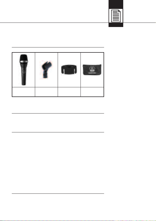
1 C 5 1 SA 45 1 PB 1000 1 Etui
L
Page 4

1.5 Kurz-
beschreibung
Das Kondensatormikrofon C 5 ist ein Vokalmikrofon für den professionellen Einsatz auf der Bühne.
Der speziell auf Gesangsübertragung abgestimmte Frequenzgang und die nierenförmige
Richtcharakteristik bieten Ihnen einen ausgewogenen Sound und hohe Rückkopplungssicherheit.
Eine robuste, nahezu unverformbare Gitterkappe
aus Federstahl und das stabile Zink-AluDruckgussgehäuse schützen das Mikrofon und
die Kapsel wirksam vor Beschädigungen im harten Alltag "on the road".
Der Aussengrill dient zusammen mit dem darunterliegenden Spezialgewebe als Windschutz, der
Pop- und Atemgeräusche sowie eine unnatürliche
Überbetonung von Zischlauten zuverlässig ausschaltet.
Der mitgelieferte Presence Boost Adapter
PB 1000 optimiert die Sprachverständlichkeit
durch eine Anhebung um etwa 5 dB zwischen
5 kHz und 9 kHz.
1 Beschreibung
4
AKG C 5
Page 5
Das C 5 ist ein Kondensatormikrofon und benötigt
daher eine Stromversorgung.
Das Mikrofon besitzt einen symmetrischen Ausgang mit 3-poligem XLR-Stecker:
Stift 1 = Masse
Stift 2 = Tonader (inphase)
Stift 3 = Tonader
1. Schließen Sie das Mikrofon mit einem XLR-Mikrofonkabel an einen symmetrischen XLR-Mikrofoneingang mit Phantomspeisung an.
2. Schalten Sie die Phantomspeisung ein. (Lesen
Sie dazu in der Betriebsanleitung des jeweiligen Gerätes nach.)
2 Anschluss
AKG C 5
5
Page 6
3.1 Einleitung
3.2 Bespre-
chungsabstand
und Naheffekt
3.3 Schalleinfallswinkel
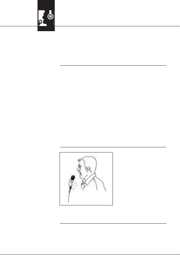
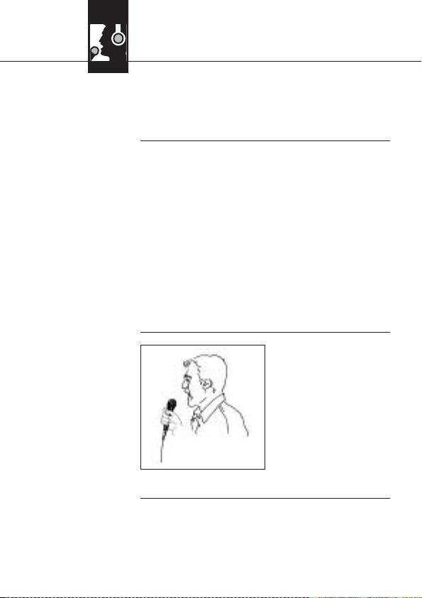
Siehe Abb. 1.
Abb. 1: Typische
Mikrofonposition
Ein Gesangsmikrofon bietet Ihnen viele Möglichkeiten, den Klang Ihrer Stimme, wie er durch die
Beschallungsanlage wiedergegeben wird, zu gestalten.
Beachten Sie bitte die folgenden Hinweise, um Ihr
Mikrofon optimal einsetzen zu können.
Grundsätzlich wird Ihre Stimme umso voller und
weicher wiedergegeben, je kürzer der Abstand
zwischen den Lippen und dem Mikrofon ist. Größere Mikrofondistanzen bewirken hingegen ein
halligeres, entfernteres Klangbild, da die Akustik
des Raumes mehr zur Geltung kommt.
Sie können daher Ihre Stimme aggressiv, neutral
oder einschmeichelnd klingen lassen, indem Sie
den Mikrofonabstand verändern.
Der Naheffekt tritt im Abstand von weniger als 5
cm von der Schallquelle auf und bewirkt eine
starke Betonung der Tiefen. Er verleiht Ihrer
Stimme einen voluminöseren, intimen, bassbetonten Klang.
Singen Sie seitlich auf
das Mikrofon oder über
den Mikrofonkopf hinweg. So erhalten Sie einen ausgewogenen, naturgetreuen Klang.
Wenn Sie direkt von
vorne auf das Mikrofon
singen, werdennicht nur
Atemgeräusche mitübertragen, sondern auch Verschlusslaute (p, t) und
Zischlaute (s, sch, tsch) unnatürlich hervorgehoben.
3 Anwendung
6
AKG C 5
Page 7
3.4 Rückkopplung
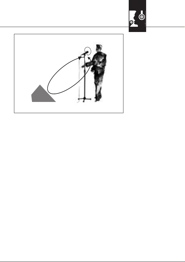
Abb. 2: Mikrofonaufstellung für minimale Rückkopplung
Siehe Abb. 2.
Rückkopplung bedeutet, dassein Teil des von den
Lautsprechern abgegebenen Schalls vom Mikrofon aufgenommen,verstärkt und wieder den Lautsprechern zugeleitet (“rückgekoppelt”) wird. Ab
einer bestimmten Lautstärke beginnt die Anlage
zu pfeifen und kann nur durch Zurückfahren der
Lautstärke wieder unter Kontrolle gebracht werden.
Um diese Gefahr zu minimieren, hat das Mikrofon
eine nierenförmige Richtcharakteristik: es ist für
Schall, der von vorne einfällt (die Stimme) am
empfindlichsten ist, während es auf seitlich oder
von hinten einfallenden Schall (z.B. von Monitorlautsprechern), kaum anspricht.
Minimale Rückkopplungsneigung erreichen Sie,
indem Sie die PA-Lautsprecher vor den Mikrofonen (am vorderen Bühnenrand) aufstellen.
Wenn Sie Monitorlautsprecher verwenden, lassen
Sie Ihr Mikrofon nie direkt auf die Monitore oder
die PA-Lautsprecher zeigen.
Rückkopplung kann auch durch Resonanzerscheinungen (als Folge der Raumakustik), beson-
3 Anwendung
AKG C 5
7
Page 8
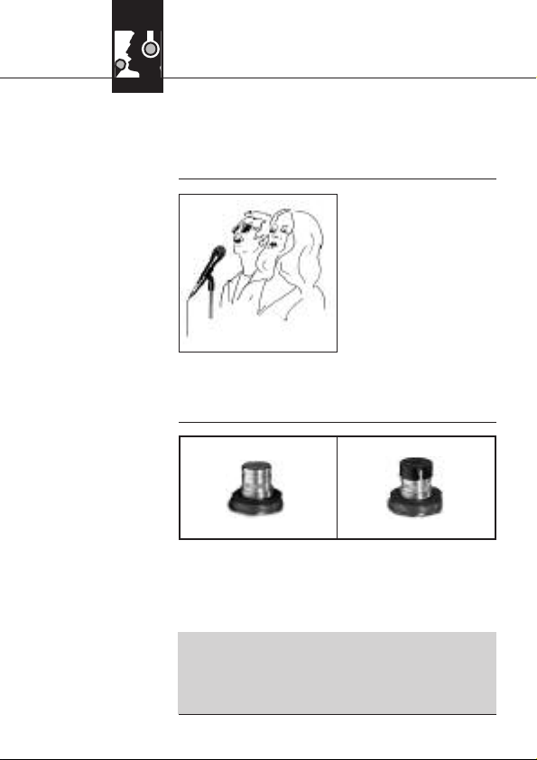
3.5 Begleitchor
Abb. 3: Mikrofon-
aufstellung für
Begleitduo
3.6 PB 1000
montieren
Abb. 4: Kapsel
ohne (a) und mit (b)
PB 1000
Wichtig!
ders im unteren Frequenzbereich, ausgelöst werden, also indirekt durch den Naheffekt. In diesem
Fall brauchen Sie oft nur den Mikrofonabstand zu
vergrößern, um die Rückkopplung zum Abreißen
zu bringen.
1. Lassen Sie nie mehr
als zwei Personen in
ein gemeinsames Mikrofon singen.
2. Das Mikrofon ist für
seitlich einfallenden
Schall sehr unempfindlich. Wenn die
beiden VokalistInnen
aus einem größeren
Winkel als 35° auf das Mikrofon singen, müssten Sie den Pegelregler des Mikrofonkanals so
weit aufziehen, dass die Rückkopplungsgefahr
zu groß würde.
1. Schrauben Sie die Gitterkappe ab.
2. Setzen Sie den PB 1000 mit einer leichten
Drehbewegung bis zum Anschlag auf die Mikrofonkapsel auf.
• Sichern Sie beim Montieren und Demontieren des PB 1000 die Mikrofonkapsel in der
elastischen Gummilagerung mit der Hand,
um die Kapsel nicht versehentlich aus der
Lagerung zu reißen.
3 Anwendung
8
AKG C 5
ab
Page 9

4.1 Gehäuseoberfläche
4.2 Innenwindschutz
• Reinigen Sie die Gehäuseoberfläche des Mikrofons mit einem mit Wasser befeuchteten
Tuch.
1. Schrauben Sie die Gitterkappe des Mikrofons
gegen den Uhrzeigersinn ab.
2. Nehmen Sie den Windschutz aus der Gitterkappe herausund reinigenSie den Windschutz
mit Seifenwasser.
3. Lassen Sie den Windschutz über Nacht trocknen.
4. Legen Sie den Windschutz in die Gitterkappe
ein und schrauben Sie die Gitterkappe im Uhrzeigersinn auf das Mikrofon auf.
4 Reinigung
AKG C 5
9
Page 10
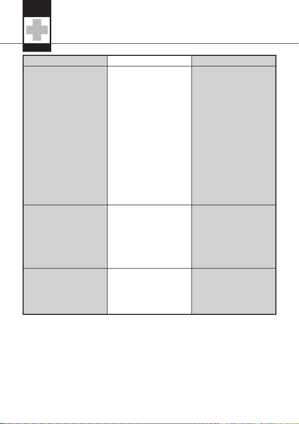
5 Fehlerbehebung
10
AKG C 5
Fehler Mögliche Ursache Abhilfe
Kein Ton.
1. Mischpult und/oder
Verstärker ausgeschaltet.
2. Kanal- oder Summen-Fader am
Mischpult oder Lautstärkeregler des Verstärkers steht auf
Null.
3. Mikrofon nicht an
Mischpult oder Verstärker angeschlossen.
4. Kabelstecker nicht
richtig angesteckt.
5. Kabel defekt.
6. Keine Speisespannung.
1. Mischpult und/oder
Verstärker einschalten.
2. Kanal-oder SummenFader am Mischpult
oder Lautstärkeregler
des Verstärkers auf
gewünschten Pegel
einstellen.
3. Mikrofon an Mischpult oder Verstärker
anschließen.
4. Kabelstecker nochmals anstecken.
5. Kabel überprüfen und
falls nötig ersetzen.
6. Phantomspeisung
einschalten.
Kabel überprüfen und
falls nötig ersetzen.
Verzerrungen.
1. Gain-Regler am
Mischpult oder Sendermodul nicht richtig
eingestellt.
2. Mischpulteingang zu
empfindlich.
1. Gain-Regler so einstellen, dass Verzerrungen verschwinden.
2. 10-dB-Vorabschwächung zwischen Mikrofonkabel und Eingang stecken.
Mikrofon klingt mit der
Zeit immer dumpfer.
• Verschmutzter Innenwindschutz oder Aussenwindschutz
dämpft hohe Frequenzen.
• Innenwindschutz
bzw. Aussenwindschutz reinigen.
Page 11
6 Technische Daten
AKG C 5
11
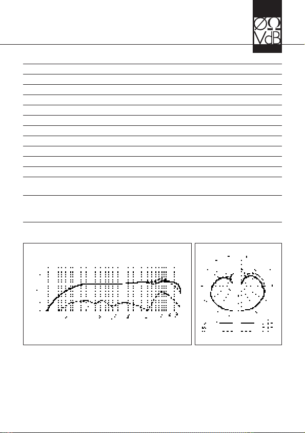
Richtcharakteristik Niere
Übertragungsbereich 65 – 20000 Hz
Leerlauf-Übertragungsfaktor 4 mV/Pa (-48 dBV bez. auf 1 V/Pa)
Grenzschalldruckpegel 140/145 dB SPL (THD =1%/3%)
Äquivalentschalldruckpegel 25 dB(A) nach DIN 45412
Elektrische Impedanz ≤ 200 Ohm
Empfohlene Lastimpedanz ≥ 2000 Ohm
Anschlussstecker XLR 3-polig
Oberfläche matt graublau
Abmessungen Länge: 185,2 mm; Ø: 51 mm
Nettogewicht 345 g
Bruttogewicht 660g
Patente Elektrodenträger eines C-Wandlers
(Patentnr. AT 392.182, DE 4.021.661)
Dieses Produkt entspricht den in der Konformitätserklärung angegebenen Normen. Sie können die Konformitätserklärung auf http://www.akg.com oder per EMail an sales@akg.com anfordern.
Frequenzgang Polardiagramm
Page 12

Page
1 Precaution / Description.....................................................13
1.1 Precaution...................................................................13
1.2 Unpacking...................................................................13
1.3 Optional Accesories....................................................13
1.4 Features ......................................................................13
1.5 Brief Description .........................................................14
2 Interfacing ...........................................................................15
3 Using Your Microphone ......................................................16
3.1 Introduction.................................................................16
3.2 Working Distance and Proximity Efffect......................16
3.3 Angle of Incidence ......................................................16
3.4 Feedback ....................................................................17
3.5 Backing Vocals............................................................18
3.6 Installing the PB 1000 .................................................18
4 Cleaning ...............................................................................19
4.1 Microphone Body .......................................................19
4.2 Internal Windscreen....................................................19
5 Troubleshooting ..................................................................20
6 Specifications......................................................................21
12
AKG C 5
Table of Contents
Page 13
1.1 Precaution
1.2 Unpacking
1.3 Optional
Accessories
1.4 Features
Please make sure that the piece of equipment
your microphone will be connected to fulfills the
safety regulations in force in your country and is
fitted with a ground lead.
Check that the packaging contains all of the components listed above. Should anything be missing, please contact your AKG dealer.
• For optional accessories, refer to the current
AKG catalog or folder, or visit www.akg.com.
Your dealer will be glad to help.
• Rugged condenser microphone for vocal miking on stage.
• Extremely resilient, spring-steelwire-mesh cap
for extra impact resistance.
• Built-in windscreen/pop filter for effective suppression of pop and breath noise.
• Transducer shock mount reduces handling and
cable noise.
• Frequency-independent cardioid polar response for high gain before feedback.
• PB 1000 Presence Boost attachment for optimum intelligibility of speech.
1 Precaution / Description
AKG C 5
13
1 C 5 1 SA 45 1 PB 1000
1 micro-
phone bag
L
Page 14
1.5 Brief
Description
The AKG C 5 is a vocal microphone for professional use on stage.
A frequency response tailored to vocal reproduction and a cardioid polar pattern provide a smooth
sound and high gain before feedback.
A ruggedfront grillmade of spring-steel wire mesh
that is extremely resistant to deformation and a
sturdy zinc alloy die-cast body effectively protect
the microphone and transducer element from
damage on stage and on the road.
The outer steel wire mesh grille and a layer of a
special fabric form a very effective windscreen
against pop and breath noise and sibilance.
The supplied PB 1000 Presence Boost attachment provides a boost of approx. 5 dB between
5 kHz and 9 kHz for optimum intelligibility of
speech.
1 Description
14
AKG C 5
Page 15
The C 5 is a condenser microphone and therefore
needs a power supply.
The microphone provides a balanced output on a
3-pin male XLR connector:
Pin 1: ground
Pin 2: hot
Pin 3: return
1. Use an XLR cable to connect the microphone
to a balanced XLR input with phantom power.
2. Switch the phantom power on. (Refer to the
manual of the unit to which you connected
your microphone.)
2 Interfacing
AKG C 5
15
Page 16
3.1 Introduction
3.2 Working
Distance and
Proximity Effect
3.3 Angle of
Incidence
Refer to fig. 1.
Fig. 1: Typical mi-
crophone position.
A handheld vocal microphone provides many
ways of shaping the sound of your voice as it is
heard over the sound system.
The followingsections contain useful hints on how
to use your microphone for best results.
Basically, your voice will sound the bigger and
mellower, the closer you hold the microphone to
your lips. Moving away from the microphone will
produce a more reverberant, more distant sound
as the microphone will pick more of the room’s reverberation.
You can use this effect to make your voice sound
aggressive, neutral, insinuating, etc. simply by
changing your working distance.
Proximity effect is a more or less dramatic boost
of low frequencies that occurs when you sing into
the microphone from less than 2 inches. It gives
more "body" to your voice and an intimate, bassheavy sound.
Sing to one side of the
microphone or above
and across the microphone’s top. This provides a well-balanced,
natural sound.
If you sing directly into
the microphone, it will
not only pick up exces-
sive breath noise but
also overemphasize "sss","sh", "tch", "p", and "t"
sounds.
3 Using Your Microphone
16
AKG C 5
Page 17

3.4 Feedback
Fig. 2: Microphone
placement for
maximum gain
before feedback.
Refer to fig. 2.
The term “feedback” means that part of the sound
projected by a speaker is picked up by a microphone, fed back to the amplifier, and projected
again by the speaker. Above a specific volume or
"system gain" setting the sound system will start
howling and the sound engineer will desperately
dive forthe master fader to reduce thevolume and
stop the howling.
To increase usable gain before feedback, the microphone has a cardioid polar pattern. It is most
sensitive to sounds arriving from in front of it (your
voice) while picking up much less of sounds arriving from the sides or rear (from monitor speakers
for instance).
To maximize gain before feedback, place the main
("FOH") speakers in front of the microphones
(along the front edge of the stage).
If youuse monitor speakers, be sure never to point
any microphone directly at a monitor or FOH
speaker.
Feedback may also be triggered by resonances
depending on the acoustics of the room or hall.
3 Using Your Microphone
AKG C 5
17
Page 18

3.5 Backing
Vocals
Fig. 3: Two
vocalists sharing a
microphone.
3.6 Installing
the PB 1000
Fig. 4: Microphone
capsule without (a)
and with (b) PB 1000.
Important!
With resonances at low frequencies, proximity effect may cause feedback. In this case, it is often
enough to move away from the microphone a little
to stop the feedback.
1. Never let more than
two persons share a
microphone.
2. The microphone is
very insensitive tooffaxis sounds. If the
two vocalists were to
sing into the microphone from an angle
wider than 35 de-
grees, you mayend up bringing up the fader of
the microphone channel far enough to create a
feedback problem.
1. Unscrew and remove the wire mesh cap.
2. Slip the PB 1000 on the microphone capsule to
the stop, slightly turning the attachment as you
push it home.
• When installing or removing the PB 1000,
make sure to grip the capsule and shock
mount firmly with your thumb and forefinger
in order to prevent the capsule being severed from the shock mount.
3 Using Your Microphone
18
AKG C 5
a
b
Page 19

4.1 Microphone
Body
4.2 Internal
Windscreen
• To clean the surface of the microphone body,
use a soft cloth moistened with water.
1. Unscrew the front grill from the microphone
CCW.
2. Remove the windscreen from the from grill and
wash the windscreen in soap suds.
3. Allow the windscreen to dry overnight.
4. Replace the windscreen in the front grill and
screw the front grill on the microphone CW.
4 Cleaning
AKG C 5
19
Page 20
5 Troubleshooting
20
AKG C 5
Problem Possible Cause Remedy
No sound.
1. Power to mixer
and/or amplifier is off.
2. Channel or master
fader on mixer, orvolume control on amplifier is at zero.
3. Microphone is not
connected to mixer or
amplifier.
4. Cable connectors are
seated loosely.
5. Cable is defective.
6. No supply voltage.
1. Switch power to
mixer or amplifier on.
2. Set channel or master
fader on mixer or volume control on amplifier to desired level.
3. Connect microphone
to mixer or amplifier.
4. Check cable connectors for secure seat.
5. Check cable and replace if damaged.
6. Switch phantom
power on.
Check cable and replace if necessary.
Distortion.
1. Gain control onmixer
or transmitter module
not set correctly.
2. Mixer input sensitivity
too high.
1. Set gain controlto
stop distortion.
2. Insert 10 dB preattenuation pad between
microphone cable
and input.
Microphone sound be-
comes duller
by and by.
• Internal or external
windscreen attenuates high frequencies
when soiled.
• Clean internal or external windscreen.
Page 21

6 Specifications
AKG C 5
21
Polar pattern: cardioid
Frequency range: 65 Hz to 20 kHz
Sensitivity: 4 mV/Pa (-48 dBV re 1 V/Pa)
Max. SPL for 1% / 3% THD: 140 / 145 dB SPL
Equivalent noise level: 25 dB(A) to DIN 45412
Impedance: ≤ 200 ohms
Re commended load impedance: ≥ 2000 ohms
Connector: 3-pin XLR
Finish: matte gray-blue
Size: length: 185.2 mm (7.3 in.);
diameter: 51 mm (2 in.)
Net weight: 345 g (12.2 oz.)
Shipping weight: 660 g (1.5 lbs.)
Patents: electrode backing for a condenser trans-
ducer (patents nos. AT 392.182,
DE 4.021.661)
This product conforms to the standards listed in the Declaration of Conformity.
To order a free copy of the Declaration of Conformity, visit http://www.akg.com
or contact sales@akg.com.
Frequency Response Polar Diagram
Page 22

Page
1 Consigne de sécurité / Description ...................................23
1.1 Consigne de sécurité ..................................................23
1.2 Fournitures..................................................................23
1.3 Accessoires optionnels...............................................23
1.4 Caractéristiques..........................................................23
1.5 Description succincte .................................................24
2 Raccordement.....................................................................25
3 Applications.........................................................................26
3.1 Introduction.................................................................26
3.2 Ecart du micrro et effet de proximité ...........................26
3.3 Angle d’incidence .......................................................26
3.4 Réacttion acoustique..................................................27
3.5 Chanteurs d’accompagnement ..................................28
3.6 Montage du PB 1000 ..................................................28
4 Nettoyage ............................................................................29
4.1 Surface du boîtier........................................................29
4.2 Bonnette antivent interne............................................29
5 Dépannage ..........................................................................29
6 Caractéristiques techniques..............................................30
22
AKG C 5
Table des matières
Page 23

1.1 Consigne de
sécurité
1.2 Fournitures
1.3 Accessoires
optionnels
1.4 Caractéristiques
Vérifiez si l’appareil auquel vous voulez raccorder
le microphone répond aux prescriptions relatives
à la sécurité en vigueur et s’il possède une mise à
la terre de sécurité.
Assurez-vous que l’emballage contient bien
toutes les pièces indiquées ci-dessus. Si ce n’est
pas le cas, contactez immédiatement votre fournisseur AKG.
• Vous trouverez la liste des accessoires option-
nels dans le catalogue/dépliant AKG actuel ou
sur www.akg.com. Votre fournisseur se tient à
votre disposition pour vous conseiller.
• Microphone électrostatique robuste pour prise
de son vocale sur la scène
• Protection efficace du transducteur par une
bonnette grillagée en acier pratiquement indéformable
• Filtre antivent et anti-pops incorporé
• Capsule montée sur suspension élastique in-
sensible aux bruits de câbleet de manipulation
• Excellente protection contre la réaction acous-
tique grâce à une courbe de réponse polaire
cardioïde indépendante de la fréquence
• Bonnette Presence Boost PB 1000 pour intelli-
gibilité de la parole optimale
1 Consigne de sécurité / Description
AKG C 5
23
1 C 5 1 SA 45 1 PB 1000
1 étui pour
microphone
L
Page 24

1.5 Description
succincte
Le C 5 d’AKG est un microphone vocalélectrostatique conçu pour l’utilisation professionnelle sur
scène.
Sa courbe de réponse en fréquence particulièrement adaptée à la voix et sa directivité cardioïde
lui confèrent une acoustique équilibrée tout en le
mettant à l’abri de toute réaction acoustique.
Une robuste bonnette grillagée en acier pratiquement indéformable et un solide corps en zamak
moulé sous pression protègent efficacement le
microphone et sa capsule contre les dommages
possibles propres aux prestations sur scène.
La grille externe doublée d’un tissu spécial fait en
même temps fonction d’écran antivent éliminant
au maximum les bruits de pop et de souffle, et les
sifflantes.
La bonnette Presence Boost PB 1000 fournie
d’origine optimise l’intelligibilité de la parole grâce
à un renforcement d’environ 5 dB entre 5 kHz et
9 kHz.
1 Description
24
AKG C 5
Page 25

Le C 5 est un microphone électrostatique ; il a
donc besoin d’une alimentation.
Le microphone possède une sortie symétrique
avec fiche XLR tripolaire :
broche 1 = masse
broche 2 = point chaud
broche 3 = point froid
Vous pouvez raccorder le microphone à volonté
sur une entrée micro symétrique avec ou sans alimentation fantôme ou bien sur une entrée asymétrique.
1. Connectez le microphone à l’aide d’un câble
de micro XLR-XLR sur une entrée de micro symétrique type XLR avec alimentation fantôme.
2. Mettez l’alimentation fantôme sous tension
(Veuillez vous reporter à la notice de l’équipement utilisé).
2 Raccordement
AKG C 5
25
Page 26

3.1 Introduction
3.2 Ecart du
micro et effet de
proximité
3.3 Angle
d’incidence
Voir Fig. 1
Fig. 1 : Position
typique du micro
Un microphone pour lechant offrede nombreuses
possibilités d’influer sur la façon dont le son de
votre voix sera restitué par l’installation de sonorisation.
Voici quelques consignes qui vous permettront
d’obtenir un résultat optimal avec votre microphone.
Plus l’écart entre le micro et la bouche est petit et
plus la sonorité de la voix est pleine et moëlleuse.
Vous obtiendrez une sonorité plus froide et plus
"reverbérante" en vous éloignant, au fur et à mesure que l’acoustique de la salle se met en valeur.
La voix peut encore prendre un ton plus agressif,
neutre ou sous entendu, etc. simplement en
changeant l’écart par rapport à la bouche.
L’effet de proximité apparait lorsque la source
est très proche (moins de 5 cm). Des basses fréquences sont renforcées, ce qui donne à la voix
plus de corps et plus de chaleur.
Pour obtenir un son naturel, bien équilibré,
nous vous conseillons
de ne jamais chanter directement dans le microphone afin d’éviter le
souffle et les sifflantes.
Il est mieux de chanter
dans le microphone en
le tenant de côté ou en
se plaçant au dessus.
3 Applications
26
AKG C 5
Page 27

3.4 Réaction
acoustique
Fig. 2: Positionnement du micro
pour minimiser le
risque de Larsen
Voir Fig. 2
L’effet Larsen prend naissance quand une partie
du sonémis parles haut-parleurs est captée par le
microphone, est amplifiée, puis est projetée à
nouveau par les haut-parleurs. A partir d’un certain niveau le système se met alors à siffler. Pour
l’interrompre, il faut réduire le volume.
Pour minimiser ce risque, le microphone a une
courbe de réponse polaire du type cardioïde. Cela
veut direqu’il est trèssensible aux sons venant de
l’avant (la voix), peu sensible à ceux venant des
côtes et pratiquement pas à tout ceux qu’il reçoit
de l’arrière.
En plaçant les haut-parleurs de chant devant les
microphones, donc sur le bord latéral de la scène
on obtient la meilleure protection contre l’effet de
Larsen.
Lorsque vous utilisez des retours de scène, ne dirigez jamais votre micro directement sur les retours ou les haut-parleurs de la sono.
Certains phénomènes de résonance (tels qu’ils
sont déterminés par l’acoustique d’une salle) peuvent également provoquer un Larsen, et cela sur-
3 Applications
AKG C 5
27
Page 28

tout dans la partie inférieure du spectre sonore;
c’est donc – indirectement – l’effet de proximité
qui en est responsable. Dans ce cas il suffit souvent d’augmenter la distance du microphone pour
faire disparaître le Larsen.
1. Ne laissez jamais
plus de deux personnes chanter dans
un seul microphone.
2. Le microphone est
extrêmement peu
sensible aux sons arrivant sur le côté. Si
la voix des deux
chanteurs arrivait sur
le micro sous un anglesupérieurà 35°, ilfaudrait
augmenter le niveau du canal micro jusqu’à un
point où le risque de larsenserait excessif.
1. Dévissez le chapeau.
2. Enfoncez le PB 1000 sur la capsule jusqu’en
butée en lui imprimant une légère rotation.
• Pendant le montage ou le démontage du
PB 1000 maintenez de l’autre main la capsule dans sa suspension élastique noire afin
d’éviter son déboîtement.
3 Applications
28
AKG C 5
3.5 Chanteurs
d’accompagne-
ment
Fig. 3 : Deux chan-
teurs avec un
seul micro
3.6 Montage
du PB 100
Fig. 4: Capsule
sans (a) et avec (b)
PB 1000
Important!
ab
Page 29

4.1 Surface du
boîtier
4.2 Bonnette
anti-vent interne
La surface extérieure du boîtier du micro se nettoie avec un chiffon légèrement humide (eau
claire).
1. Dévissez la grille externe du micro dans le sens
contraire aux aiguilles d'une montre.
2. Retirez la bonnette anti-vent de son logement
et nettoyez-la à l'eau savonneuse.
3. Laissez la bonnette anti-vent sécher pendant
la nuit.
4. Replacez la bonnette anti-vent dans la grille
externe et vissez la grille sur le microphone
dans les sens des aiguilles d'une montre.
4 Nettoyage
AKG C 5
29
Page 30

5 Dépannage
30
AKG C 5
Problème Cause possible Remède
Pas de son
1. La console de
mixage/ l’ampli n’est
pas sous tension.
2. Le fader de voie ou
de mélange sur la
console de mixage ou
le régulateur de volume de l’ampli est
sur zéro.
3. Le microphone n’est
pas connecté à la
console de mixage ou
à l’ampli.
4. La fiche du câble
n’est pas branchée
correctement.
5. Le câble est défectueux.
6. Pas de tension d’alimentation.
1. Mettre la consolede
mixage/l’ampli sous
tension.
2. Régler le fader de
voie ou de mélange
sur la console de
mixage ou le régulateur de volume de
l’ampli sur le niveau
voulu.
3. Connecter le microphone à la console de
mixage ou à l’ampli.
4. Sortir la fiche de la
prise et la rebrancher.
5. Contrôler le câble et
le remplacer le cas
échéant.
6. Mettre l’alimentation
fantômesous tension.
Contrôler le câble et
le remplacer le cas
échéant.
Distorsions
1. Le réglage de gain de
la console de mixage
ou du module émetteur n’est pas correct.
2. L’entrée dela console
de mixage est trop
sensible.
1. Régler le gain de manière à supprimer les
distorsions.
2. Intercaler un pré-atténuateur de sensibilité
de 10 dB entre le câble de micro et l’entrée.
Le son du microphone
est de plus en plus
sourd
• L’écran antivent interne ou externe est
encrassé et atténue
les fréquences élevées.
• Nettoyer l’écran antivent interne ou externe.
Page 31

6 Caractéristiques techniques
AKG C 5
31
Directivité: cardioïde
Réponse en fréquence: 65 … 20.000 Hz
Sensibilité : 4 mV/Pa (-48 dBV rapp. à 1 V/Pa)
Niveau maximum de pression sonore pour un
facteur de distorsion de 1% / 3%: 140 / 145 dB SPL
Niveau de bruit équivalent: 25 dB(A) (selon DIN 45412)
Impédance électrique à 1.000 Hz: ≤ 200 ohms
Impédance de charge recommandée:≥ 2000 ohms
Connecteur: type XLR, 3 points
Couleur: mat gris-bleu
Dimensions: longueur: 185,2 mm, diamètre: 51 mm
Poids net 345 g
Poids d’expédition: 660 g
Brevets: Porte-électrodes d’un transducteur de con
densateur (brevets N° AT 392.182,
DE 4.021.661)
Ce produit est conforme aux normes citées dans la Déclaration de Conformité,
dont vous pouvez prendre connaissance en consultant le site http://www.akg.com
ou en adressant un e-mail à sales@akg.com.
Réponse en fréquence Diagramme polaire
Page 32

Pagina
1 Indicazione per la sicurezza / Descrizione........................33
1.1 Indicazione per la sicurezza........................................33
1.2 In dotazione ................................................................33
1.3 Accessori opzionali.....................................................33
1.4 Caratteristiche particolari............................................33
1.5 Breve descrizione........................................................34
2 Collegamento ......................................................................35
3 Impiego ................................................................................36
3.1 Introduzione ................................................................36
3.2 Distanza microfonica ed effetto di prossimità .............36
3.3 Angolo di incidenza del suono ....................................36
3.4 Reazione .....................................................................37
3.5 Coro di accompagnamento ........................................38
3.6 Montaggio del PB 1000...............................................38
4 Pulizia...................................................................................39
4.1 Superficie del microfono .............................................39
4.2 Antisofffio interno........................................................39
5 Errori e rimedi ......................................................................40
6 Dati tecnici...........................................................................41
32
AKG C 5
Indice
Page 33

1.1 Indicazione
per la sicurezza
1.2 In dotazione
1.3 Accessori
opzionali
1.4 Caratteristiche particolari
Controllate per favore se l’apparecchio che volete
collegare al microfono corrisponde alle norme di
sicurezza vigenti e se è dotato di una messa a
terra di sicurezza.
Controllate per favore se la confezione contiene
tutti i componenti di cui sopra. Se manca qualcosa rivolgetevi al vostro rivenditore AKG.
• Accessori opzionali si trovano nel catalogo/folder attuale dell'AKG o al sito www.akg.com. Il
vostro rivenditore è a vostra disposizione per
eventuali consigli.
• Robusto microfono a condensatore per la ripresa vocale in palco
• Sicura protezione del trasduttore microfonico
grazie alla griglia in acciaio per molle praticamente non deformabile.
• Filtro antivento e antipop che elimina efficacemente i rumori di pop e quelli della respirazione
• Alloggiamento elastico del sistema trasduttore
che riduce i rumori provocati dall’impugnatura
e dal cavo
• Buona riduzione della reazione acustica tramite caratteristica direzionale cardioide indipendente dalla frequenza
1 Indicazione per la sicurezza / Descrizione
AKG C 5
33
1 C 5 1 SA 45 1 PB 1000
1 taschetta
per microfono
L
Page 34

1.5 Breve
descrizione
• Adattatore Presence Boost PB 1000 che ottimizza l’intelligibilità della parola
Il microfono a condensatore C 5 dell’AKG è un microfono vocale sviluppato appositamente per
l’impiego professionale sul palco. La risposta in
frequenza armonizzata in modo speciale sulla trasmissione di canto e ladirettività cardioide offrono
un suono ben equilibrato ed una grande sicurezza
antireazione.
La robusta griglia, praticamente non deformabile,
realizzata in acciaio per molle, e la resistente scatola in zinco-alluminio pressofuso proteggono il
microfono e la capsula efficientemente dai danni
causati dalla dura routine "on the road".
La griglia esterna serve, insieme al tessuto speciale sottostante, come protezione antivento che
elimina in modo affidabile i rumori prodotti dal
vento, rumori pop e un’esaltazione innaturale di
suoni sibilanti.
L’adattatore Presence Boost PB 1000 in dotazione ottimizza l’intelligibilità della parola mediante una enfatizzazione di 5 dB entro 5 kHz e
9 kHz.
1 Descrizione
34
AKG C 5
Page 35

Il C 5 è un microfono a condensatore e ha quindi
bisogno di alimentazione.
Il microfono è dotato di un’uscita simmetrica con
connettore XLR a 3 poli.
Pin 1 = massa
Pin 2 = filo audio (inphase)
Pin 3 = filo audio
1. Collegate il microfono ad un ingresso microfonico XLR simmetrico con alimentazione phantom servendovi di un cavo microfonico XLR.
2. Inserite l’alimentazione phantom. (Leggete in
merito le istruzioni per l’uso del rispettivo apparecchio.)
2 Collegamento
AKG C 5
35
Page 36

Un microfono per canto vi offre diverse possibilità
di variare il suono della vostra voce riprodotto dall’impianto di sonorizzazione.
Osservate perfavorei seguenti avvertimenti per poter impiegareil vostromicrofono in modo ottimale.
Fondamentalmente, la Vostra voce guadagnerà in
pienezza e morbidezza in funzione della vicinanza
tra le labbra ed il microfono. Ad una maggior distanza dal microfono si produce invece uno spettro acustico di maggior riverbero e più distante,
poiché viene esaltata l’acustica dell’ambiente.
Potrete quindi conferire alla Vostra voce un suono
aggressivo, neutro o carezzevole, semplicemente
modificando la distanza dal microfono.
L’effetto di prossimità si produce a distanze mi-
crofoniche di meno di 5 cm e provoca una forte
esaltazione dei bassi. Può conferire maggiore voluminosità alla voce oppure un suono intimo, marcato dalle tonalità basse.
Cantate lateralmente rispetto al microfono o al
di sopra del microfono.
In tal modo otterrete un
suono equilibrato e naturale.
E investite il microfono
con la voce direttamente da davanti, tra-
smettereste nel canto
anche i rumori connessi alla respirazione, e i suoni
occlusivi (p, t) e sibilanti (s, sc, c) verrebbero esaltati in maniera innaturale.
3 Impiego
36
AKG C 5
3.1 Introduzione
3.2 Distanza
microfonica
ed effetto di
prossimità
3.3 Angolo di
incidenza
del suono
Vedi fig. 1.
Fig. 1: Posizione ti-
pica del microfono
Page 37

3.4 Reazione
Fig. 2: Posizionamento del microfono per minimizzare il rischio di
reazione
Vedi fig. 2.
La reazione significa che il suonoemesso dall’amplificatore viene in parte ripreso dal microfono che
lo reinvia, amplificato, all’altoparlante. A partire da
un determinato volume, l’impianto comincia a fischiare e può venir "silenziato" solo diminuendo il
volume.
Al fine di prevenire questo rischio, il microfono del
microfono dispone di una caratteristica direzionale cardioide: è particolarmente sensibile al
suono cheinveste il microfono dadavanti (p. es. la
voce), mentre quasi non registra il suono che proviene dai lati o da dietro (p. es. dagli altoparlanti
monitor).
La massima sicurezza antireazione si ottiene posizionando le casse PA davanti ai microfoni, vale a
dire sul margine anteriore del palco.
Se usatealtoparlanti monitor, non puntate il vostro
microfono mai direttamente sui monitor o sugli altoparlanti dell’impianto di sonorizzazione.
La reazione può essere causata anche da risonanze (determinatedall’acustica dell’ambiente), in
particolare nella gamma di frequenze bassa, indi-
3 Impiego
AKG C 5
37
Page 38

rettamente quindi dall’effetto di prossimità. In
questi casi spesso è sufficiente aumentare la distanza dal microfono per interrompere la reazione.
1. Non lasciate mai
cantare più di due
persone per microfono.
2. Il microfono è molto
insensibile al suono
che entra di lato. Se i
due vocalisti cantano
verso il microfono da
un angolo maggiore
di 35°, dovreste regolare il livello del canale microfonico in modo tale che il pericolo di feedback diventerebbe troppo grande.
1. Svitate la griglia esterna.
2. Infilate il PB 1000 sulla capsula microfonica
fino all’arresto girandolo leggermente.
• Per il montaggio e lo smontaggio del PB
1000, assicurate con la mano la capsula nel
supporto elastico di gomma nera, per evitare di staccare non volutamente la capsula
dal supporto.
3 Impiego
38
AKG C 5
3.5 Coro di
accompagna-
mento
Fig. 3: Posiziona-
mento del micro-
fono per due
cantanti
3.6 Montaggio
del PB 1000
Fig. 4: Capsula
senza (a) e
con (b) PB 1000
Importante!
a
b
Page 39

4.1 Superficie
del microfono
4.2 Antisoffio
interno
• Pulite la superficie della scatola del microfono
con un panno inumidito con acqua.
1. Svitate la griglia esterna delmicrofono insenso
antiorario.
2. Tirate l'antisoffio fuori della griglia e lavatelo
con acqua e sapone.
3. Lasciate l'antisoffio asciugare per tutta la
notte.
4. Rimettete l'antisoffio nella griglia esterna ed
avvitate la griglia sul microfono in senso orario.
4 Pulizia
AKG C 5
39
Page 40

5 Errori e rimedi
40
AKG C 5
Errrore Possibile causa Rimedio
Non c’è suono.
1. Mixer e/o amplificatore disinserito.
2. Fader del canale o fader principale sul mixer o regolatore del
volume dell’amplificatore in posizione
zero.
3. Il microfono nonè
collegato al mixer o
all’amplificatore.
4. Il connettore delcavo
non è inserito bene.
5. Il cavo è difettoso.
6. Non c’è alimentazione.
1. Inserire il mixere/o
amplificatore.
2. Portare il faderdel
canale o il fader principale sul mixer o il
regolatore delvolume
dell’amplificatore sul
livello desiderato.
3. Collegare il microfono
al mixer o all’amplificatore.
4. Inserire un’altra volta
il connettore del
cavo.
5. Controllare il cavo e
sostituirlo se necessario.
6. Inserire l’alimentazione phantom.
Controllare ilcavo e,
se necessario, sostituirlo.
Distorsioni
1. Il regolatore Gain sul
mixer o sul modulo di
trasmissione non è
regolato bene.
2. L’ingresso del mixer è
troppo sensibile.
1. Portare il regolatore
Gain in posizione tale
da far sparire le distorsioni.
2. Inserire una preattenuazione da 10 dB tra
cavo microfonico ed
ingresso.
Il suono del microfono
diventa sempre più cupo
con l’andar del tempo.
• L’antisoffio interno o
esterno è sporco e attenua le frequenze
alte.
• Pulire l’antisoffio interno o quello esterno.
Page 41

6 Dati tecnici
AKG C 5
41
Direttività: cardioide
Risposta in frequenza: 65 - 20.000 Hz
Sensibilità: 4 mV/Pa (-48 dBV rif. a 1 V/Pa)
Livello di pressione acustica limite
per un coefficiente di
distorsione armonica di 1% / 3%: 140 / 145 dB SPL
Livello di pressione acustica
equivalente: 25 dB(A) secondo DIN 45412
Impedenza elettrica a 1000 Hz: ≤ 200 ohm
Impedenza di carico raccomandata: ≥ 2000 ohm
Connettore: XLR a 3 poli
Superficie: grigio-azzurro opaco
Dimensioni: lunghezza: 185,2 mm, diametro: 51 mm
Peso netto 345 g
Peso brutto: 660 g
Brevetti: supporto elettrodi di un trasduttore a con
densatore (brevetto n. AT 392.182,
DE 4.021.661)
Questo prodotto corrisponde alle norme elencate nella dichiarazione di conformità, che è disponibile al sito http://www.akg.com oppure all'indirizzo email
sales@akg.com.
Risposta in frequenza Diagramma polare
Page 42

Página
1 Indicaciones de seguridad / Descripción..........................43
1.1 Indicaciones de seguridad..........................................43
1.2 Volumen de suministro................................................43
1.3 Accesorios opcionales................................................43
1.4 Características especiales..........................................43
1.5 Breve descripción.......................................................44
2 Conexión .............................................................................45
3 Utilización ............................................................................46
3.1 Introducción................................................................46
3.2 Distancia del micrófono y efecto de proximidad.........46
3.3 Angulo de incidencia del sonido .................................46
3.4 Retroalimentación.......................................................47
3.5 Coro de acompañamiento ..........................................48
3.6 Montaje del PB 1000...................................................48
4 Limpieza...............................................................................49
4.1 Superficie del micrófono .............................................49
4.2 Pantalla antiviento interna...........................................49
5 Reparación de desperfectos..............................................50
6 Datos técnicos ....................................................................51
42
AKG C 5
Indice
Page 43

Sírvase verificar si el aparato al cual quiere conectar el micrófono cumple con las disposiciones de
seguridad vigentes y está equipado con una toma
de tierra de seguridad.
Sírvase controlar si el embalaje contiene todas las
piezas indicadas arriba. Si falta algo, le rogamos
dirigirse a su distribuidor AKG.
• Los accesorios opcionales los encontrará en el
más reciente Catálogo/Folleto de AKG o en
www.akg.com. Su distribuidor lo asesorará
con mucho gusto.
• Robusto micrófono de condensador para
transmisión vocal en el escenario.
• Protección segura del transductor por la rejilla
prácticamente indeformable de acero para
muelles.
• El filtro de viento y de ruidos integrado suprime
eficazmente los ruidos de pop y de respiración.
• El alojamiento elástico del transductor reduce
los ruidos de manipulación y de cable.
• Buena supresión de la retroalimentación por la
característica direccional cardioide independiente de la frecuencia.
1 Indicaciones de seguridad / Descripción
AKG C 5
43
1.1 Indicaciones
de seguridad
1.2 Volumen de
suministro
1.3 Accesorios
opcionales
1.4 Características especiales
L
1 C 5 1 SA 45 1 PB 1000
1 bolsillo de
micrófono
Page 44

1.5 Breve
descripción
• El adaptador Presence Boost PB 1000 optimiza la inteligibilidad de la palabra.
El micrófonode condensador C 5es un micrófono
vocal para el uso profesional en el escenario.
La respuesta de frecuencia ajustada a la transmisión vocal y la característica direccional cardioide
ofrecen un sonido equilibrado y una buena supresión de la retroalimentación.
Una rejilla robusta, prácticamente indeformable
de acero para muelles y la caja troquelada de cinc
y aluminio muy estable, protegen el micrófono y la
cápsula eficazmente contra daños en el duro quehacer cotidiano cuando se está "on the road".
La rejilla exterior y la tela especial debajo de la
misma sirven de pantalla antiviento que excluye
con seguridad los ruidos de soplido y de viento,
así como la acentuación exageradade sonidos sibilantes.
El adaptador Presence Boost PB 1000 fornecido
con el micrófono optimiza la inteligibilidad de la
palabra mediante un refuerzo de aprox. 5 dB entre
5 kHz y 9 kHz.
1 Descripción
44
AKG C 5
Page 45

El C 5 es un micrófono de condensador y necesita, por lo tanto, alimentación de corriente.
El micrófono dispone de una salida simétrica con
conector XLR de 3 polos:
Clavija 1 = tierra
Clavija 2 = audio (en fase)
Clavija 3 = audio
1. Conecte el micrófono a una entrada de micrófono XLR balanceada con alimentación fantasma utilizando un cable XLR de micrófono.
2. Concecte la alimentación fantasma (consulte
para ello el Modo de empleo del aparato correspondiente).
2 Conexión
AKG C 5
45
Page 46

Un micrófono de canto ofrece muchas posibilidade de configurar la voz tal como es reproducida
por el equio de sonorización.
Se ruega atenerse a las indicaciones siguientes
para poder utilizar el micrófono en forma óptima.
Por principio, su voz se reproduce más plena y
suave cuanto menor es la distancia entre los labios y el micrófono. A mayores distancias del micrófono, se produce una tonalidad más reverberante y más lejana, dado que la acústica del local
se manifiesta en mayor medida.
Puede dar a su voz un toque agresivo, neutro o insinuante, modificando tan sólo la distancia del
micrófono.
El efecto de proximidad se produce a distancias
de menosque 5 cm y provoca una fuerte acentuación de los bajos. La voz parece más voluminosa
o adquiera un tono intimo de bajos acentuados.
Cante lateralmente sobre el micrófono o por
encima de la cabeza del
micrófono. De este
modo, consigue un sonido equilibrado y natural.
Si canta directamente
desde delante sobre el
micrófono, no sólo se
transmiten los ruidos de la respiración, sino que
se resaltan también de forma no natural los sonidos oclusivos (p, t) y sibilantes (s, ch).
3 Utilización
46
AKG C 5
3.1 Introducción
3.2 Distancia del
micrófono y
efecto de
proximidad
3.3 Angulo de
incidencia
del sonido
Véase Fig. 1.
Fig. 1: Posición tí-
pica del micrófono
Page 47

3.4 Retroalimentación
Fig. 2: Emplazamiento del micrófono para prevenir
la retroalimentación
Véase Fig. 2.
La retroalimentación significa que una parte del
sonido emitido por el amplificador es captado por
el micrófono, amplificado y devuelto a los altavoces. Apartir de un determinado volumen acústico,
el equipo aúlla y silba y sólo puede ponerse de
nuevo bajo control reduciendo el volumen.
Para prevenir este riesgo, el micrófono tiene una
característica direccional cardioide: es lo más
sensible al sonido procedente desde delante (p.
ej. la voz), mientras reacciona apenas al sonido
que llegadesde los lados o desde atrás(p. ej. altavoces monitor).
La mayor seguridad contra laretroalimentación se
consigue situando los altavoces delante de los
micrófonos, es decir, en el borde delantero del escenario.
Si se utilizanaltavoces de monitor, el micrófono no
debe estar orientado nunca directamente hacia
los monitores o los altavoces de sonorización.
La retroalimentación puede ser provocada también por fenómenos de resonancia (determinados
por la acústica del recinto en cuestión), particular-
3 Utilización
AKG C 5
47
Page 48

mente enla gama de frecuencias baja; esdecir, de
forma indirecta por el efecto de proximidad. En
este caso basta a menudo con aumentar la distancia hacia el micrófono para cortar la retroalimentación.
1. No deberían cantar
nunca más de dos
personas en el
mismo micrófono.
2. El micrófono es muy
poco sensible a sonidos que llegan lateralmente. Si dos vocalistas cantaran en
el micrófono a un án-
gulo superior a 35° se tendría que abrir tanto el
regulador de nivel del canal de micrófono que
sería muy grande el peligro de retroalimentación.
1. Desatornille la rejilla.
2. Atornille el PB 1000 con un ligero movimiento
giratorio hasta que llegue al tope.
• Durante el montaje y desmontaje del PB
1000 sujete la cápsula en la suspensión
elástica de goma negra con la mano para
evitar arrancar inadvertidamente la cápsula
de la suspensión
3 Utilización
48
AKG C 5
3.5 Coro de
acompaña-
miento
Fig. 3: Dos
cantantes con un
micrófono
3.6 Montaje del
PB 1000
Fig. 4: Cápsula
sin (a) y con (b)
el PB 1000
¡Importante!
ab
Page 49

4.1 Superficie
del micrófono
4.2 Pantalla antiviento interna
• Limpie la superficie de la caja del micrófono
con un paño humedecido con agua.
1. Desatornille la rejilla exterior del micrófono en
sentido contrario al reloj.
2. Quite la pantalla antiviento de la rejilla exterior
y limpie la pantalla antiviento con lejía sabonosa.
3. Deje la pantalla antiviento secar durante la noche.
4. Inserte la pantalla antiviento en larejilla exterior
y tornille la rejilla exterior al micrófono en sentido del reloj.
4 Limpieza
AKG C 5
49
Page 50

5 Reparación de desperfectos
50
AKG C 5
Desperfecto Causa posible Remedio
No hay sonido.
1. Están desconectados
el pupitre de mezcla
y/o el amplificador.
2. El desvanecedor de
canal o de suma del
pupitre mezclador o
el regulador de volumen del amplificador
están en cero.
3. El micrófono no está
conectado al pupitre
de mezcla o al amplificador.
4. El tomacorriente no
está bien enchufado.
5. El cable está defectuoso.
6. No hay tensión de alimentación.
1. Conectar el pupitre
de mezcla y/o el amplificador.
2. Poner el desvanecedor de canal o de
suma del pupitre
mezclador o del amplificador en el nivel
deseado.
3. Conectar el micrófono al pupitre de
mezcla o al amplificador.
4. Volver a enchufar correctamente el tomacorriente.
5. Verificar el cable y
sustituirlo, de ser necesario.
6. Conecte la alimentación fantasma.
Controle el cable y,si
es necesario, reemplácelo.
Distorsiones.
1. En el pupitrede mezcla o en el módulo
transmisor no está
bien ajustado el regulador de ganancia.
2. La entrada del pupitre
de mezcla está demasiado sensible.
1. Ajustar el regulador
de ganancia de tal
forma que desaparezcan las distorsiones.
2. Enchufar una preatenuación de 10 dB entre el cable del micrófono y la entrada.
El micrófono se va ha-
ciendo cada vez más
sordo.
• La pantalla antiviento
interior o exterior atenúa las frecuencias
altas.
• Limpiar la pantalla
antiviento interior o
exterior.
Page 51

6 Datos técnicos
AKG C 5
51
Característica direccional: Cardioide
Gama de frecuencia: 65 - 20000 Hz
Sensibilidad: 4 mV/Pa (-48 dB referido a 1 V/Pa)
Presión sonora límite para factor
de distorsión no lineal de 1% / 3%: 140 / 145 dB SPL
Nivel de ruido equivalente: 25 dB(A) según DIN 45412
Impedancia eléctrica a 1000 Hz: ≤ 200 ohmios
Impedancia de carga recomendada:≥ 2000 ohmios
Tipo de conector: XLR de 3 polos
Superficie: Gris azulado mate
Dimensiones: Largo: 185,2 mm, diámetro: 51 mm
Peso neto 345 g
Peso bruto: 660 g
Patentes: Soporte de electrodos de un sistema micro
fónico (Núm. de patente: AT 392.182,
DE 4.021.661)
Este aparato corresponde a las normas citadas en la declaración de conformidad. Esta última está disponible en el sitio http://www.akg.com o puede ser solicitada al correo electrónico sales@akg.com.
Respuesta de frecuencia Diagrama polar
Page 52

Página
1 Aviso de segurança/Descrição ..........................................53
1.1 Aviso de segurança.....................................................53
1.2 Volume de fornecimento.............................................53
1.3 Acessórios opcionais..................................................53
1.4 Características especiais............................................53
1.5 Apresentação..............................................................54
2 Conexão...............................................................................55
3 Aplicação .............................................................................56
3.1 Introdução...................................................................56
3.2 Distância de captação e efeito de proximidade..........56
3.3 Ângulo de incidência do som ......................................56
3.4 Realimentação ............................................................57
3.5 Coro acompanhante...................................................58
3.6 Instalar o PB 1000.......................................................58
4 Limpeza ...............................................................................59
4.1 Superfície do microfone..............................................59
4.2 Paravento interno........................................................59
5 Resolver problemas............................................................60
6 Especificações ....................................................................61
52
AKG C 5
Índice
Page 53

1.1 Aviso de
segurança
1.2 Volume de
fornecimento
1.3 Acessórios
opcionais
1.4 Características especiais
Certifique-se de que o aparelho ao qual pretende
ligar o microfone está ligado à terra e que corresponde às normas de segurança.
Verifique se a embalagem contém todos os componentes acima indicados. Caso falte algo, favor
entre em contato com a concessionária da AKG.
• Os acessórios opcionais encontrará no catálogo/ na brochura atual d a AKG ou em
www.akg.com. A concessionária terá mais informações disponíveis.
• Microfone condensador robusto para captação vocal em palcos.
• Proteção segura do transdutor do microfone
através da tampa de grade de aço para molas
quase indeformável.
• Paravento e filtro pop integrado para a supressão eficaz de ruídos de pop e respiração.
• Suporte elástico do transdutor para suprimir
de formaeficaz os ruídos provocados pela manipulação e pelo cabo.
• Alta segurança quanto à realimentação através da característica cardióide independente
da freqüência.
• Adaptador Presence Boost PB 1000 para otimizar a clareza da palavra.
1 Aviso de segurança / Descrição
AKG C 5
53
L
1 C 5 1 SA 45 1 PB 1000
1 estojo de
microfone
Page 54

1.5
Apresentação
O microfone condensador C 5 é um microfone vocal para o uso profissional no palco.
Sua resposta de freqüência projetada especialmente para captar a voz proporciona um som
equilibrado e a característica direcional cardióide
reduz o risco de realimentação.
Uma tampa gradeada quase indeformável de aço
de mola assim como a carcaça estável moldada
sob pressão de zinco-alumínio protegem de
forma eficaz omicrofone ea cápsula de danos durante o uso diário "on the road".
A grade externa, juntamente com o tecido especial por baixo, serve como paravento eliminando
ruídos de pop e de sopro, assim como uma acentuação exagerada de sons sibilantes.
O adaptador Presence Boost PB 1000 incluído na
embalagem proporciona um pico de aprox. 5 dB
entre 5 kHz e 9 kHz para otimizar a clareza da palavra.
1 Descrição
54
AKG C 5
Page 55

O C 5 é um microfone de condensador e por isso
precisa de uma alimentação de corrente.
O microfone possui uma saída balanceada com
um plugue XLR com 3 pólos:
Pino 1 = massa
Pino 2 = áudio (em fase)
Pino 3 = áudio
1. Ligue o microfone com um cabo XLR a uma
entrada demicrofone XLRbalanceada com alimentação fantasma.
2. Ligue a alimentação fantasma. (Veja as instruções de uso do equipamento ao qual o microfone está ligado.)
2 Conexão
AKG C 5
55
Page 56

3.1 Introdução
3.2 Distância de
captação e
efeito de
proximidade
3.3 Ângulo de
incidência
do som
Veja fig. 1.
Fig. 1: Posição tí-
pica do microfone
Um microfone de canto proporciona-lhe muitas
possibilidades de modificar o som da sua voz
como é produzido através da instalação de sonorização.
Preste atenção às seguintes instruções para aplicar o seu microfone de melhor forma possível.
Em geral a sua voz será reproduzida de forma
mais branda e mais suave quanto mais curta for a
distância entre os lábios e o microfone, enquanto
com uma maior distância do microfone o som
será reproduzido de forma mais distante e mais
retumbante porque a acústica da sala se manifesta mais forte.
Por isso pode dar à sua voz uma aparência mais
agressiva, neutra, ou mais suave, alterando a
distância do microfone.
O efeito de proximidade surge a uma distância
de menos de 5 cm, enfatizando mais os graves.
Torna o somda sua voz maisprofundo, volumoso,
íntimo, dando mais força às freqüências baixas.
Cante no microfone
duma posição lateral ou
acima do microfone.
Desta forma obtém um
som equilibrado e natural.
Se cantar diretamente
no microfone serão
transmitidos não só os
ruídos da respiração,
mas também os sons fechados (t, p), e os sons sibilantes (s, ch, tch) são enfatizados de maneira
não natural.
3 Aplicação
56
AKG C 5
Page 57

3.4
Realimentação
Fig. 2: Posicionamento do microfone para minimizar o risco de realimentação.
Veja fig. 2.
A realimentação surge porque uma parte do som
emitido pelos alto-falantes é captado pelo microfone, amplificado e de novo alimentado aos altofalantes. A partir de um certo volume a instalação
de som uiva e apita, e pode ser controlada só girando o botão do volume para uma posição de
volume menor.
Para minimizar este perigo, o microfone possui
uma característica cardióide: é mais sensível ao
som que entra pela frente (a voz), enquanto quase
não capta o som que entra pelo lado ou do lado
de trás (p.ex. de alto-falantes de monitoreado).
A menor possibilidade de realimentação é garantida ao posicionar os alto-falantes PA em frente
dos microfones (na borda da frente do palco).
Se usar alto-falantes de monitoreado nunca direcione o seu microfone para os monitores ou os
alto-falantes PA.
A realimentação poderá ser provocada também
por efeitos de ressonância (em conseqüência da
acústica da sala) especialmente na faixa das freqüências baixas, ou seja, indiretamente pelo
3 Aplicação
AKG C 5
57
Page 58

3.5 Coro
acompanhante
Fig. 3: Duas pes-
soas usando um
microfone só.
3.6 Instalar
o PB 1000
Fig. 4: Cápsula
sem (a) e com (b) o
PB 1000
Importante!
efeito de proximidade. Neste caso freqüentemente só precisa de aumentar a distância do microfone para acabar com a realimentação.
1. Nunca deixe mais de
duas pessoas usar o
mesmo microfone.
2. O microfone é muito
insensível ao som
que entra pelo lado.
Se os/as vocalistas
cantarem num ângulo maior de 35º em
relação ao microfone,
deveria posicionar o regulador do nível do canal do microfone tão alto que o perigo de realimentação acústica seria demasiadamente
grande.
1. Desaparafuse e remova a grade.
2. Encaixe o PB 1000 completamente na cápsula
com um ligeiro movimento giratório, até que
chegue ao esbarro.
• Quando instala ou remove o PB 1000 certifique-se de apertar a cápsula e a suspensão
elástica de borracha negra para evitar de a
cápsula ser separada da suspensão elástica.
3 Aplicação
58
AKG C 5
a
b
Page 59

4.1 Superfície
do microfone
4.2 Paravento
interno
• Limpe a superfície da carcaça do microfone
com um pano molhado em água.
1. Desande a grade externa do microfone no sentido inverso ao dos ponteiros do relógio.
2. Remova o paravento da grade externa e lave-o
com água de sabão.
3. Deixe o paravento secar durante a noite.
4. Insira o paravento na grade externa e fixe a
grade externa ao microfone girando-a no sentido dos ponteiros do relógio.
4 Limpeza
AKG C 5
59
Page 60

5 Resolver problemas
60
AKG C 5
Problema Causa possível Como resolver
Não há som.
1. A mesa de mixagem/o amplificador
está desligado(a).
2. O fader do canal ou
de soma na mesa de
mixagem ou o regulador de volume do
amplificador está em
zero.
3. O microfone nãoestá
ligado à mesa de mixagem ou ao amplificador.
4. O plugue do cabo
não está conectado
corretamente.
5. O cabo tem defeito.
6. Não há tensão de alimentação.
1. Ligar a mesa de mixagem/o amplificador.
2. Ajustar o fader do canal ou de soma na
mesa de mixagem ou
o regulador de volume do amplificador
ao nível desejado.
3. Ligar o microfoneà
mesa de mixagem ou
ao amplificador.
4. Conectar o plugue do
cabo novamente.
5. Controlar o caboe
substituí-lo, se for necessário.
6. Ligar a alimentação
fantasma.
Verificar o cabo e
substituir,se for necessário.
Distorções.
1. O controle Gainna
mesa de mixagem ou
no módulo de emissor não está ajustado
corretamente.
2. A entrada da mesa de
mixagem é muito
sensível.
1. Ajustar o controlede
maneira que as distorções desapareçam.
2. Inserir um pré-atenuador de 10 dB entre o cabo de microfone e a entrada.
O microfone soa cada
vez mais indistinto.
• O paravento externo
ou interno está suja e
por isso atenua freqüências altas.
• Limpar o paravento
externo ou interno.
Page 61

6 Especificações
AKG C 5
61
Caraterística direcional: cardióide
Resposta de freqüência: 65 - 20.000 Hz
Sensibilidade: 4 mV/Pa (-48 dBV ref. a 1 V/Pa)
Pressão sonora limite para
1% / 3% de distorsão: 140 / 145 dB SPL
Nível equivalente de ruído: 25 dB(A) conforme DIN 45412
Impedância elétrica: ≤ 200 ohms
Impedância de carga recomendada:≥ 2000 ohms
Tipo de conetor: XLR tripolar
Superfície: azul-cinzento mate
Dimensões: comprimento: 185,2 mm,
diâmetro: 51 mm
Peso líquido 345 g
Peso bruto: 660 g
Patentes: Porta-eletrodos dum transdutor de conden-
sador. (Patente no. AT 392.182,
DE 4.021.661)
Este produto corresponde às normas citadas na declaração de conformidade,
que pode pedir na nossa página da web http://www.akg.com, ou enviando-nos
um email para sales@akg.com.
Resposta de freqüência Diagrama polar
Page 62

NNoottiizzeenn -- NNootteess -- NNootteess -- NNoottee -- NNoottaass -- NNoottaas
s
62
AKG C 5
Page 63

NNoottiizzeenn -- NNootteess -- NNootteess -- NNoottee -- NNoottaass -- NNoottaas
s
AKG C 5
63
Page 64

Mikrofone · Kopfhörer · Drahtlosmikrofone · Drahtloskopfhörer · Kopfsprechgarnituren · Akustische Komponenten
Microphones · Headphones · Wireless Microphones · Wireless Headphones · Headsets · Electroacoustical Components
M
icrophones · Casques HiFi · Microphones sans fil · Casques sans fil · Micros-casques · Composants acoustiques
Microfoni · Cuffie HiFi · Microfoni senza filo · Cuffie senza filo · Cuffie-microfono · Componenti acustici
Micrófonos · Auriculares · Micrófonos inalámbricos · Auriculares inalámbricos · Auriculares con micrófono · Componentes acústicos
Microfones · Fones de ouvido · Microfones s/fios · Fones de ouvido s/fios · Microfones de cabeça · Componentes acústicos
Technische Änderungen vorbehalten. Specifications subject to change without notice. Ces caractéristiques sont susceptibles de modifications.
Ci riserviamo il diritto di effettuare modifiche tecniche. Nos reservamos el derecho de introducir modificaciones técnicas. Especificações sujeitas
a mudanças sem aviso prévio.
AKG Acoustics GmbH
Lemböckgasse 21–25, A-1230 Vienna/AUSTRIA, phone: (+43-1) 86654-0*
e-mail: sales@akg.com
AKG Acoustics, U.S.
8500 Balboa Boulevard, Northridge, CA 91329, U.S.A, phone: (+1 818) 920-3212
e-mail: akgusa@harman.com
For other products and distributors worldwide visit www.akg.com
Printed in Austria on recycled paper. 09/06/9100 U 1205
 Loading...