

Page 1
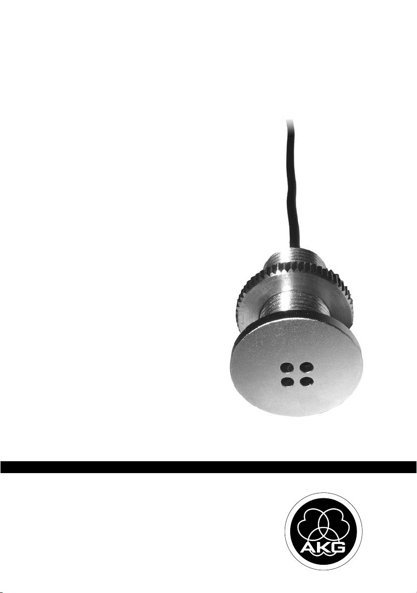
C562 CM
BEDIENUNGSANLEITUNG . . . . . . . . . .S. 2
Bitte vor Inbetriebnahme des Gerätes lesen!
USER INSTRUCTIONS . . . . . . . . . . . . . . .p. 10
Please read the manual before using the equipment!
MODE D’EMPLOI . . . . . . . . . . . . . . . . . . . . .p. 18
Veuillez lire cette notice avant d’utiliser le système!
ISTRUZIONI PER L’USO . . . . . . . . . . . . .p. 26
Prima di utilizzare l’apparecchio, leggere il manuale!
MODO DE EMPLEO . . . . . . . . . . . . . . . . . . .p. 34
¡Sirvase leer el manual antes de utilizar el equipo!
INSTRUÇÕES DE USO . . . . . . . . . . . . . . .S. 42
Favor leia este manual antes de usar o equipamento!
Page 2

Inhaltsverzeichnis
Seite
1 Sicherheit und Umwelt.........................................................................................3
Sicherheit..............................................................................................................3
Umwelt..................................................................................................................3
2 Beschreibung.......................................................................................................4
Einleitung ..............................................................................................................4
Lieferumfang.........................................................................................................4
Optionales Zubehör ................................................................................................4
Kurzbeschreibung ..................................................................................................4
3 Stromversorgung.................................................................................................5
4 Montage...............................................................................................................6
5 Anwendungshinweise .........................................................................................7
6 Technische Daten.................................................................................................9
2 C 562 CM
Page 3

1 Sicherheit und Umwelt
• Überprüfen Sie bitte, ob das Gerät, an welches Sie das Mikrofon anschließen
möchten, den gültigen Sicherheitsbestimmungen entspricht und mit einer Sicherheitserdung versehen ist.
1. Wenn Sie das Gerät verschrotten, trennen Sie Gehäuse, Elektronik und Kabel und entsorgen Sie alle Komponenten gemäß den dafür geltenden Entsorgungsvorschriften.
2. Die Verpackung ist wiederverwertbar. Entsorgen Sie die Verpackung in einem dafür vorgesehenen Sammelsystem.
Sicherheit
Umwelt
3C 562 CM
Page 4
2 Beschreibung
Einleitung
Lieferumfang
Optionales Zubehör
Kurzbeschreibung
Vielen Dank, dass Sie sich für ein Produkt aus dem Hause AKG entschieden haben. Bitte
lesen Sie die Bedienungsanleitung aufmerksam durch, bevor Sie das Gerät benützen,
und bewahren Sie die Bedienungsanleitung sorgfältig auf, damit Sie jederzeit nachschlagen
können. Wir wünschen Ihnen viel Erfolg!
• Mikrofon C 562 CM mit Befestigungsmaterial (Rändelmutter) und fix montiertem Kabel,
0,5 m lang, mit 3,5-mm-Klinkenstecker
• Phantomspeiseadapter mit XLR-Stecker und 0,5 m langem Kabel mit 3,5-mm-
Monoklinkenbuchse
• Optionales Zubehör finden Sie im aktuellen AKG-Katalog/Folder oder auf www.akg.com.
Ihr Händler berät Sie gerne.
Das C 562 CM ist ein Grenzflächenmikrofon und wird so in eine akustisch reflektierende
Fläche eingebaut, dass die Einspracheöffnung auf die Schallquelle gerichtet ist und das Mikrofon in einer Ebene mit der akustisch reflektierenden Fläche zu liegen kommt. Diese Montagemethode verhindert Kammfiltereffekte oder andere Interferenzen, die auftreten können,
wenn ein Mikrofon in der Nähe einer reflektierenden Fläche betrieben wird.
Sie können das Mikrofon in eine Pultplatte, Tischplatte, Wand oder Zimmerdecke einbauen.
(Um die einwandfreie Funktion sicherzustellen, darf das Mikrofongehäuse keinen Kontakt zu
geerdeten Metallteilen haben.)
Die Richtwirkung des Mikrofons ist etwa halbkugelförmig. Die Empfindlichkeit ist ca. 6 dB
höher als die eines herkömmlichen Kugelmikrofons, wenn das Mikrofon in einer schallharten Trägerfläche montiert ist. Der Wandler des C 562 CM ist ein Kugelmikrofon nach dem
Druckempfänger-Prinzip und daher wesentlich unempfindlicher gegen Trittschall und Windgeräusche als ein Richtmikrofon.
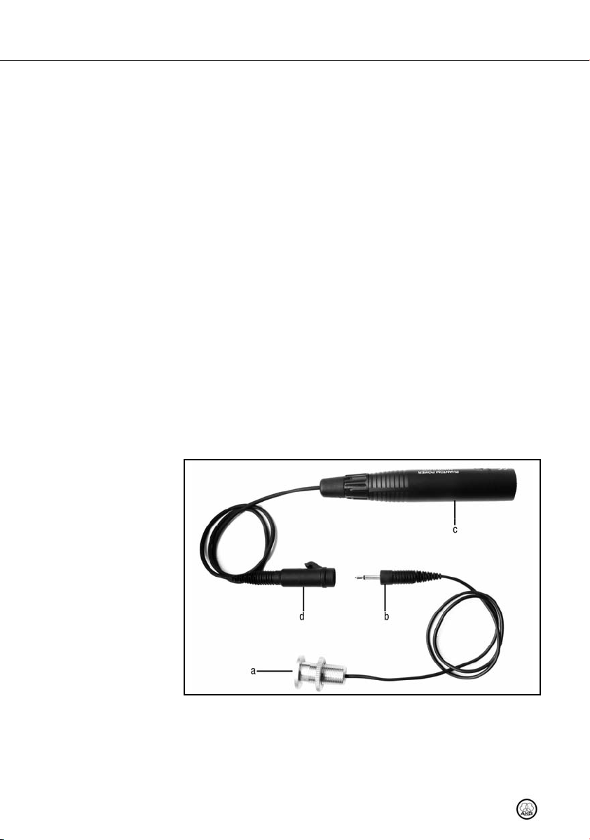
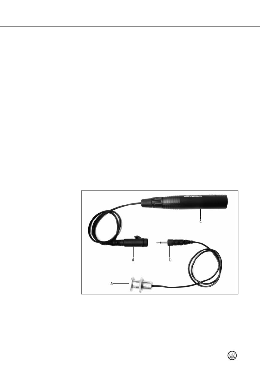
Abb. 1: C 562 CM
und Phantomspeiseadapter
Siehe Abb. 1.
4 C 562 CM
Das C 562 CM besteht aus dem eigentlichen Mikrofon (a) mit fix verbundenem Kabel
(0,5 m lang) mit 3,5-mm-Monoklinkenstecker (b) zum Einbau in eine Grenzfläche und einem
separaten Phantomspeiseadapter (c) mit fix verbundenem Kabel (0,5 m lang) und 3,5-mmMonoklinkenbuchse (d). Der Ausgang des Phantomspeiseadapters (Mikrofonausgang mit
integriertem XLR-Stecker) ist niederohmig und elektronisch symmetriert, und kann an symmetrische und unsymmetrische Mikrofoneingänge angeschlossen werden.
Page 5

Das C 562 CM zeichnet sich durch niedriges Eigenrauschen und gleichzeitig hohe Übersteuerungsfestigkeit aus. Dieses Mikrofon benötigt eine Phantomspeisung von 9 bis 52 V
nach IEC 61938.
• Verbinden Sie das Mikrofon ausschließlich mit Phantom speisequellen (Eingang
mit Phantomspeisung oder externes Phantomspeisegerät) nach IEC mit erdfreiem Anschluss und verwenden Sie dazu ausschließlich ein symmetrisches
Kabel mit Studiosteckverbindern nach IEC 268-12. Nur so kann ein sicherer
und problemloser Betrieb garantiert werden.
3 Stromversorgung
WICHTIG
5C 562 CM
Page 6
4 Montage
Sie können das Mikrofon in Grenzflächen mit einer maximalen Dicke von 19 mm einbauen.
1. - 2. 3. - 4. 5.
d
d
d
d
e
e
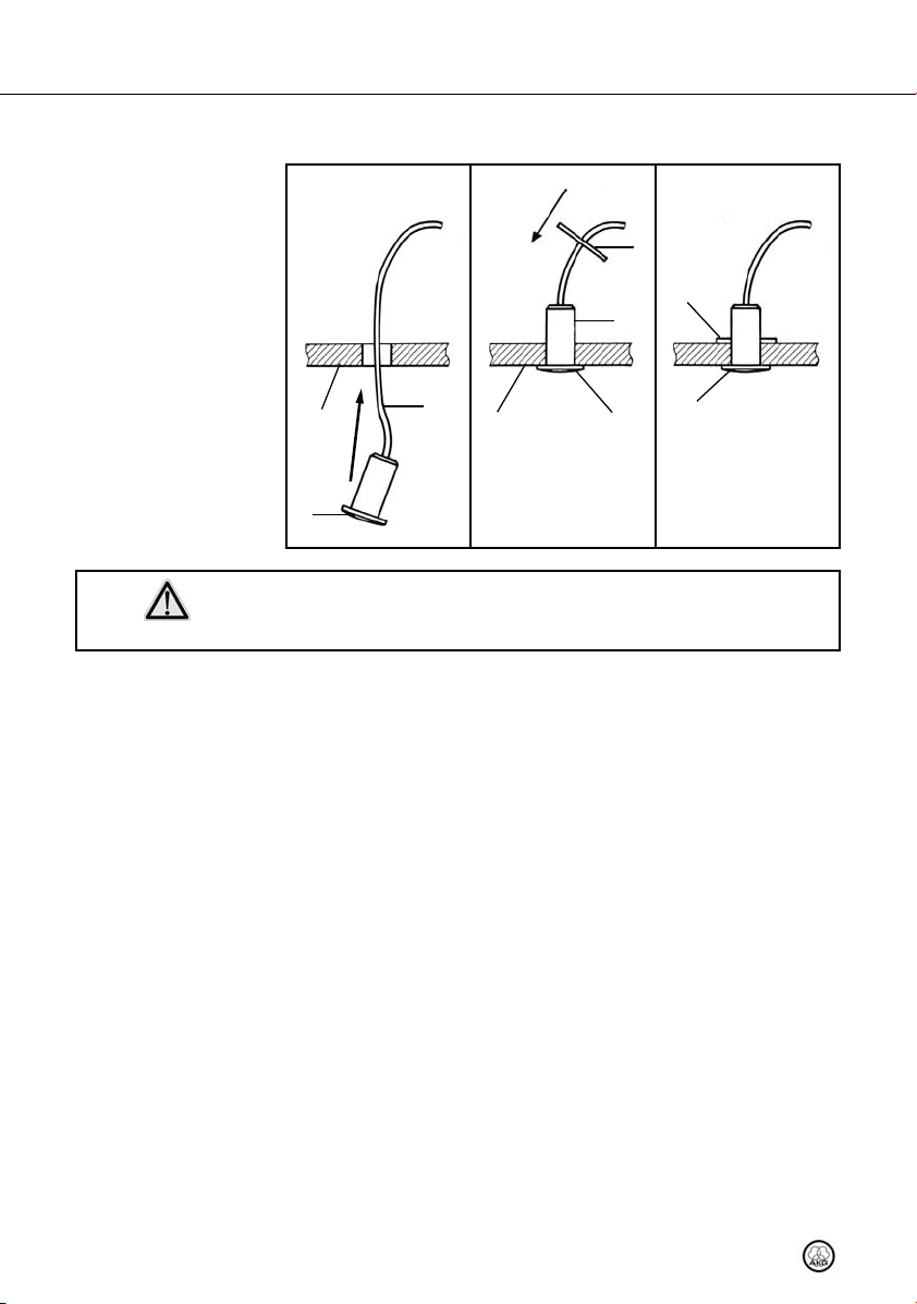
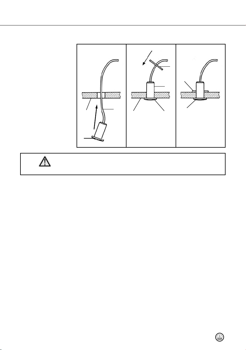
Abb. 2: Mikrofon in
Grenzfläche einbauen
WICHTIG
Siehe Abb. 2.
b
a
a
c
c
b
a
a
c
c
c
c
• Um die einwandfreie Funktion sicherzustellen, sorgen Sie dafür, dass das Mikrofongehäuse keinen Kontakt zu geerdeten Metallteilen hat.
1. Bohren Sie in die Grenzfläche (a) eine Öffnung mit 12,5 mm Durchmesser.
2. Fädeln Sie das Mikrofonkabel (b) von der Sichtfläche her durch die Öffnung und schieben Sie das Mikrofon (c) bis zum Anschlag in die Öffnung ein.
3. Drücken Sie das Mikrofon (c) gegen die Grenzfläche (a).
4. Schieben Sie die Rändelmutter (d) über den Klinkenstecker und das Mikrofonkabel auf
den Mikrofonschaft (e).
5. Ziehen Sie die Rändelmutter (d) soweit an, dass das Mikrofon (c) sicher gehalten wird.
6 C 562 CM
Page 7
5 Anwendungshinweise
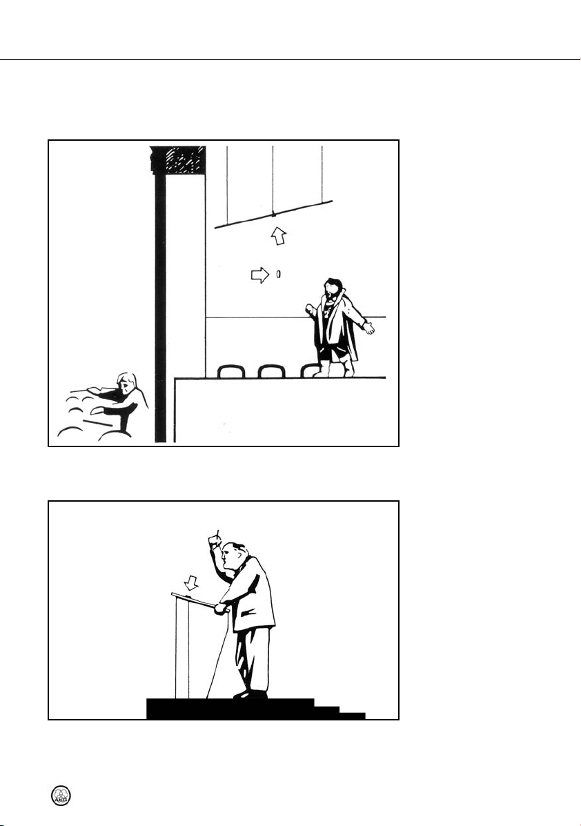
Das C 562 CM ist einfach einzubauen, klein, unauffällig und bietet eine hervorragende Aufnahmequalität. Deshalb eignet es sich besonders gut zur Nahfeldmikrofonierung von "mikrofonscheuen" Personen und für Anwendungen, wo aus optischen bzw. ästhetischen
Gründen kein Mikrofon sichtbar sein darf.
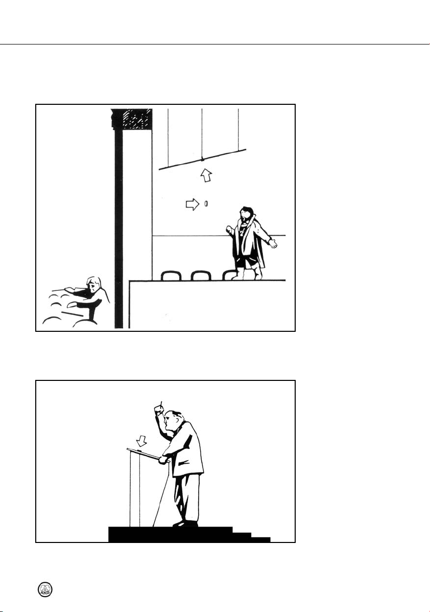
Beispiel 1:
Theaterbeschallung
Abb. 3: Montage an Kulissen
• Bauen Sie das Mikrofon in eine schallharte Wand (nicht aus Dämmplatten, ohne Tapete)
in der Nähe der Schallquelle ein. Am besten eignen sich ebene Wände aus akustisch reflektierendem Material.
• Bauen Sie das Mikrofon direkt in das Rednerpult bzw. die Kanzel ein. Durch den weiten
Aufnahmewinkel des Mikrofons kann sich der/die Redner/in frei bewegen, ohne große
C 562 CM
Siehe Abb. 3.
Beispiel 2:
Rednerpult, Kanzel
Abb. 4: Einbau in
Rednerpult/Kanzel
Siehe Abb. 4.
7
Page 8
5 Anwendungshinweise
Schwankungen des Signalpegels zu verursachen. Zusätzlich stört kein Mikrofon den
Blickkontakt mit dem Publikum.
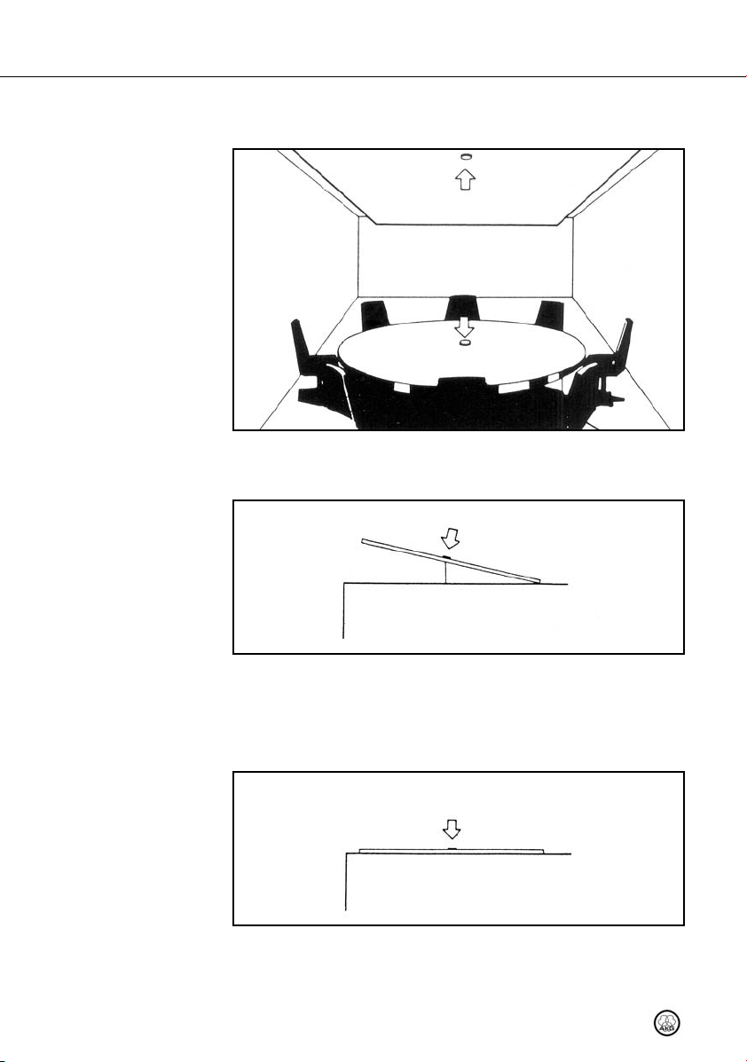
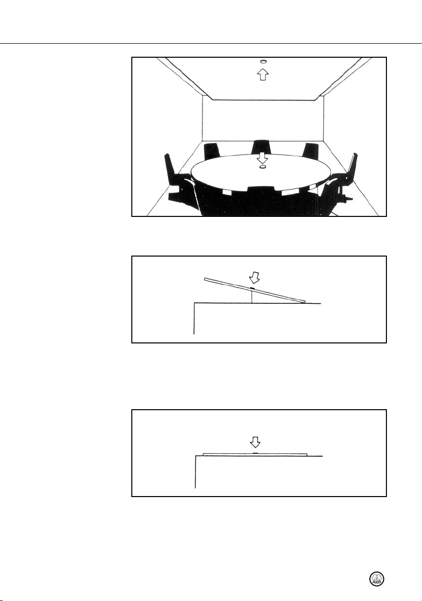
Beispiel 3:
Konferenzraum
Abb. 5: Einbau in
Konferenz tisch und Decke
Siehe Abb. 5.
Weitere Hinweise
Abb. 6: Störende
Schallquellen ausblenden
Siehe Abb. 6.
Abb. 7: Vibrationsdämpfung
Siehe Abb. 7.
• In Konferenzräumen können Sie das Mikrofon entweder in den Konferenztisch oder ein
oder mehrere Mikrofone in die Deckenverkleidung (sofern diese schallhart ist!) einbauen.
• Die halbkugelförmige Richtcharakteristik kann zu ungewollten Aufnahmen aus nicht berücksichtigten Richtungen führen. Wenn die Grenzfläche beweglich und nicht zu groß ist,
können Sie das Mikrofon von der störenden Schallquelle weg drehen.
Sie können auch versuchen, die störende Schallquelle mit Plexiglas-Paneelen ausreichender Größe (1 x 1 m) oder dickem Teppichmaterial abzuschatten.
• Eine gute Vibrationsdämpfung können Sie erreichen, indem Sie ein schalldämmendes
Material (z.B. Weichschaum) unter die akustisch reflektierende Fläche legen.
8 C 562 CM
Page 9
6 Technische Daten
Arbeitsweise: Kondensator (selbstpolarisiert)
Richtcharakteristik: halbkugelförmig
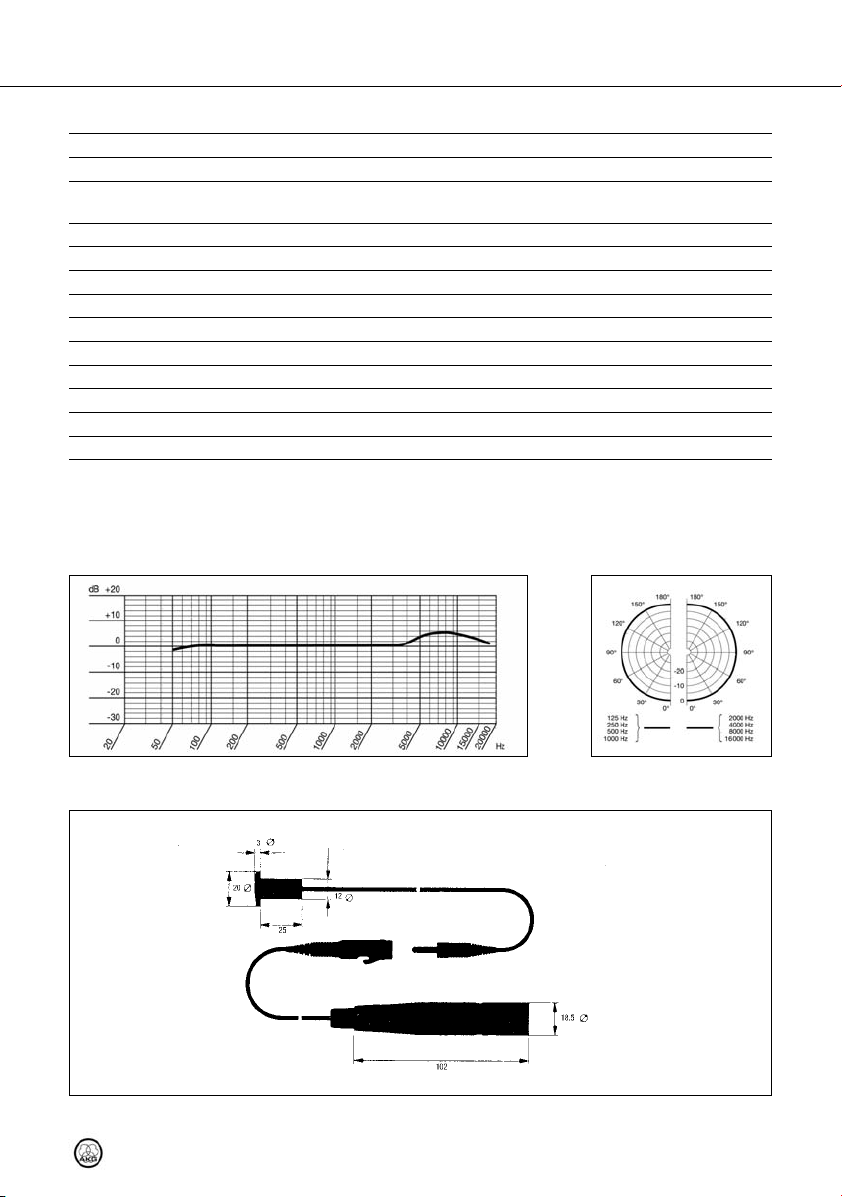
Übertragungsbereich: 20 bis 20.000 Hz (auf sehr großer Grenzfläche))
Empfindlichkeit bei 1000 Hz: 20 mV/Pa (-33 dBV) bez. auf 1 V/Pa (gemessen mit Grenzfläche
Grenzschalldruck für k = 1% : 130 dB SPL
Äquivalentschalldruckpegel nach IEC 60268-4 (A-bewertet):16 dB(A)
Geräuschpegelabstand bez. auf 1 Pa (A-bewertet): 78 dB
Elektrische Impedanz: ≤ 600 Ohm
Empfohlene Lastimpedanz: ≥ 2000 Ohm
Speisespannung: 9 - 52 Volt Phantomspeisung nach IEC 61938
Stromaufnahme: ca. 2 mA
Stecker: Phantomspeiseadapter mit integriertem 3-poligem XLR-Stecker
Äußere Abmessungen: 20 ø x 3 (28) mm
Gewicht: ~30 g netto (ohne Anschlusskabel)
Dieses Produkt entspricht den in der Konformitätserklärung angegebenen Normen. Sie können die Konformitätserklärung auf
http://www.akg.com oder per E-Mail an sales@akg.com anfordern.
Frequenzkurve Polardiagramm
von 1,5 x 1,5 m)
Maßzeichnung
C 562 CM
9
Page 10

Table of Contents
Page
1 Safety and Environment.....................................................................................11
Safety .................................................................................................................11
Environment ........................................................................................................11
2 Description ........................................................................................................12
Introduction .........................................................................................................12
Packing List.........................................................................................................12
Optional Accessories ............................................................................................12
Brief Description ..................................................................................................12
3 Powering ...........................................................................................................13
4 Installation.........................................................................................................14
5Use.....................................................................................................................15
6 Specifications....................................................................................................17
10 C 562 CM
Page 11

1 Safety and Environment
• Please make sure that the piece of equipment your microphone will be connected to fulfills the safety regulations in force in your country and is fitted with
a ground lead.
1. When scrapping the equipment, separate the case, circuit boards, and cables, and dispose of all components in accordance with local waste disposal rules.
2. The packaging of the equipment is recyclable. To dispose of the packaging, make sure
to use a collection/recycling system provided for that purpose and observe local legislation relating to waste disposal and recycling.
Safety
Environment
11C 562 CM
Page 12
2 Description
Introduction
Packing List
Optional Accessories
Brief Description
Thank you for purchasing an AKG product. This Manual contains important instructions for
setting up and operating your equipment. Please take a few minutes to read the instruc-
tions below carefully before operating the equipment. Please keep the Manual for future reference.
• C 562 CM microphone with mounting hardware (knurled nut) and fixed 20-in. (50-cm)
cable with mini jack plug
• Phantom power adapter with XLR connector and 20-in. (50-cm) cable with female
mini jack plug
• For optional accessories, refer to the current AKG catalog or folder, or visit www.akg.com.
Your dealer will be glad to help.
The C 562 CM is a boundary microphone designed to be installed in a sound reflecting surface such that the diaphragm will be flush with the surface and face the sound source. This
prevents comb filter effects or other interference that may arise when a microphone is placed
close to a reflecting surface.
You can install the C 562 CM in a desk top, table top, wall, or ceiling. (In order for the microphone to function properly, the microphone body should not make contact with any
grounded metal parts.)
The polar pattern of the microphone is approximately hemispherical. When installed in a reflective surface, the C 562 CM's sensitivity is 6 dB higher than that of a convention al omnidirectional microphone. Using an omnidirectional pressure transducer, the C 562 CM is
much less susceptible to mechanical and wind noise than a cardioid.
Fig. 1: C 562 CM and
phantom power adapter.
Refer to fig. 1.
12 C 562 CM
The C 562 CM comprises the flush mount microphone (a) with a 20-in. (50-cm) fixed cable
terminated in a TS mini jack plug (b) and a separate phantom power adapter (c) with 20-in.
(50-cm) fixed cable and female TS mini jack plug (d). The phantom power adapter features
a low-impedance, electronically balanced output and can be connected to balanced or unbalanced inputs.
Page 13

The C 562 CM provides low self-noise yet high headroom. The microphone requires a phantom power source providing 9 to 52 V as per IEC 61938.
• Do not connect the microphone to any power supply other than a phantom
power source (input with phantom power or external IEC standard phantom
power supply) with a floating connector, using a balanced cable with studio
grade connectors to IEC 268-12 only. This is the only way to ensure safe and reliable operation.
3 Powering
IMPORTANT
C 562 CM
13
Page 14
4 Installation
You can install the microphone in a panel with a maximum thickness of 6/8" (19 mm).
1. - 2. 3. - 4. 5.
d
d
d
d
e
e
Fig. 2: Installing the micro-
phone in a boundary.
IMPORTANT
Refer to fig. 2.
b
a
a
c
c
b
a
a
c
c
c
c
• To ensure proper functioning, make sure that the microphone body will not
make contact with any grounded metal parts.
1. Drill a hole ½" (12.5 mm) in diameter in the boundary (a).
2. Thread the cable (b) though the hole from the front and push the microphone (c) all the
way in.
3. Press the microphone (c) against the boundary (a).
4. Slip the knurled nut (d) over the jack plug and cable and onto the microphone shaft (e).
5. Tighten the knurled nut (d) to the point that the microphone (c) is firmly held in place.
14 C 562 CM
Page 15
The C 562 CM is small, easy to install, inconspicuous, and provides outstanding recording
quality. It is therefore an excellent choice for close-miking people shying away from microphones and applications where no microphone must be visible for visual or esthetic reasons.
5 Use
Example 1: Theater stage
miking
Fig. 3: Installation in stage decoration parts.
Install the microphone in a reflective wall (covered with no wallpaper of sound absorbing
•
material) near the sound source. The wall should be as even and reflective as possible.
• Install the microphone directly in the lectern or pulpit. Due to the wide pickup angle of
the microphone, the talker is free to move without causing wide variations in signal level.
Also, the microphone will be practically invisible.
Refer to fig. 3.
Example 2: Lectern or pulpit
Fig. 4: Installation in a lectern
or pulpit.
Refer to fig. 4.
15C 562 CM
Page 16
Example 3:
Conference room
Fig. 5: Installation in a confer-
ence table and ceiling.
Refer to fig. 5.
More hints
Fig. 6: Minimizing sound
pickup from unwanted
sources.
Refer to fig. 6.
Fig. 7: Reducing
mechanical noise.
Refer to fig. 7.
• In a conference room, you can install either a single microphone in a conference table
or one or more microphones in a reflective ceiling panel.
• The hemispherical polar pattern may cause unwanted sounds from unexpected directions to be picked up. Unless the boundary is too large or permanently installed, simply
turn the panel with the microphone away from the unwanted source.
Alternatively, you can place suitably sized (4x4 ft. / 1x1 m) plexiglass panels or thick-pile
carpet between the microphone and the unwanted sound source(s).
• You can reduce mechanical noise to a minimum by placing a layer of sound absorbing
material (e.g., soft foam) beneath the reflective panel.
16 C 562 CM
Page 17

6 Specifications
Type: condenser microphone (self-polarized)
Polar pattern: omnidirectional (hemispherical)
Frequency response: 20 Hz to 20 kHz (installed in very large boundary)
Sensitivity at 1000 Hz: 20 mV/Pa (-33 dBV) re 1 V/Pa (measured on 1.5 x 1.5 m
Max. sound pressure level for 1% THD: 130 dB SPL
Equivalent noise level to IEC 60268-4 (A-weighted): 16 dB(A)
S/N ratio re 1 Pa (A-weighted): 78 dB
Electrical impedance: ≤ 600 ohms
Recommended load impedance: ≥ 2000 ohms
Powering: 9 to 52 V phantom power to IEC 61938
Current consumption: approx. 2 mA
Connector: phantom power adapter with integrated male 3-pin XLR
Size: 0.8 dia. x 0.12 (1.1) in. (20 dia. x 3 (28) mm)
Net weight: approx. 1.1 oz. (30 g) (without cable)
This product conforms to the standards listed in the related Declaration of Conformity. To order a free copy of the Declaration
of Conformity for this product, visit http://www.akg.com or contact sales@akg.com.
Frequency Response Polar Diagram
boundary)
connector
Dimensioned Drawing
C 562 CM
17
Page 18

Sommaire
Page
1 Sécurité et environnement.................................................................................19
Sécurité ..............................................................................................................19
Environnement.....................................................................................................19
2 Description ........................................................................................................20
Introduction .........................................................................................................20
Fournitures d’origine ............................................................................................20
Accessoires optionnels .........................................................................................20
Description succincte ...........................................................................................20
3 Alimentation ......................................................................................................21
4 Montage.............................................................................................................22
5 Utilisation...........................................................................................................23
6 Caractéristiques techniques ..............................................................................25
18 C 562 CM
Page 19

1 Sécurité et environnement
• Vérifiez si l’appareil sur lequel vous voulez brancher le microphone répond aux
règlements de sécurité en vigueur et possède une prise de terre de sécurité.
1. Si vous mettez le micro à la ferraille, démontez boîtier, électronique et câbles et éliminez chacun de ces éléments conformément aux prescriptions en vigueur.
2. L'emballage est recyclable. Déposez l'emballage dans un récipient de collecte prévu à
cet effet.
Sécurité
Environnement
19C 562 CM
Page 20

2 Description
Introduction
Fournitures d’origine
Accessoires optionnels
Description succincte
Nous vous remercions d’avoir choisi un produit d’AKG et vous invitons à lire attentivement
le présent mode d’emploi avant de mettre votre micro en service. Conservez soi-
gneusement le mode d’emploi pour l’avoir toujours sous la main lorsque vous avez besoin
de le consulter. Nous espérons que vous aurez beaucoup de satisfaction et de succès avec
votre micro.
• Microphone C 562 CM avec matériel de montage (écrou moleté) et câble fixe de
0,5 m avec fiche jack mono de 3,5 mm
• Adaptateur pour alimentation fantôme avec fiche XLR et câble de 0,5 m avec prise
jack mono de 3,5 mm
• Vous trouverez la liste des accessoires optionnels dans le catalogue/dépliant AKG actuel
ou sur www.akg.com. Votre fournisseur se tient à votre disposition pour vous conseiller.
Le C 562 CM est un microphone de surface, le micro étant incorporé à une surface réfléchissante de telle manière que le diaphragme soit orienté vers la source sonore et le micro
se trouve dans le même plan que la surface à réflexion acoustique. Cette méthode de montage évite les effets de filtre en peigne ou d'autres interférences susceptibles de se produire lorsqu'un micro se trouve à proximité d'une surface réfléchissante.
Vous pouvez monter le micro dans le plateau d'un pupitre ou d'une table, une paroi ou le
plafond de la pièce. (Pour garantir le bon fonctionnement du micro, le boîtier du micro ne doit
pas être en contact avec des éléments métalliques reliés à la terre.)
La directivité du microphone est théoriquement hémisphérique. Sa sensibilité est supérieure
de 6 dB environ à celle d'un microphone omnidirectif classique lorsque le micro est monté
dans une surface de fixation réfléchissante. Le transducteur omnidirectif utilisé est un microphone à pression ayant l'avantage d'être beaucoup moins sensible aux bruits de pas et
de vent.
Fig. 1 : C 562 CM
et adaptateur fantôme
Voir Fig. 1.
20 C 562 CM
Le C 562 CM comprend le microphone proprement dit (a) avec câble fixe (0,5 m) et prise
jack mono de 3,5 mm (b) pour le montage dans une surface réfléchissante et un adaptateur fantôme (c) avec câble fixe (0,5 m) et fiche jack femelle de 3,5 mm (d). La sortie de
l'adaptateur fantôme (la sortie du micro avec fiche XLR intégrée) est une sortie à basse impédance, équilibrée électroniquement, qui peut être raccordée à des entrées pour micros symétriques ou asymétriques.
Page 21

Le C 562 CM se distingue par son bruit propre faible s’accompagnant d’un très faible risque
de surcharge. Ce micro nécessite une alimentation fantôme de 9 à 52 V selon IEC 61938.
• Utilisez le microphone exclusivement avec une source d’alimentation fantôme
(entrée disposant d’une alimentation fantôme ou bloc d’alimentation fantôme
externe) à la norme CEI sans mise à la terre, et employez à cet effet uniquement
un câble symétrique équipé de broches professionnelles à la norme CEI 268-12.
Ce n’est qu’ainsi que vous avez la garantie d’un fonctionnement sûr et sans
problèmes.
3 Alimentation
IMPORTANT
C 562 CM
21
Page 22

4 Montage
La surface dans laquelle vous montez le microphone ne doit pas avoir plus de 19 mm
d'épaisseur.
1. - 2. 3. - 4. 5.
d
d
d
d
e
e
Fig. 2 : Montage du micro
dans une surface
réfléchissante
IMPORTANT
Voir Fig. 2.
b
a
a
c
c
b
a
a
c
c
c
c
• Pour garantir le bon fonctionnement du micro, veillez à ce que le boîtier du
micro ne soit pas en contact avec des éléments métalliques reliés à la terre.
1. Percez dans la surface de fixation (a) un trou de 12,5 mm de diamètre.
2. Introduisez le câble du micro (b) par l'extérieur et enfoncez le micro (c) jusqu'en butée.
3. Maintenez le micro (c) dans cette position.
4. Glissez l'écrou moleté (d) par l'arrière sur le corps du micro (e), en le faisant passer sur
la fiche jack.
5. Vissez l'écrou moleté (d) jusqu'à la surface de fixation pour maintenir le micro (c) en
position de butée.
22 C 562 CM
Page 23

Les avantages du C 5612 CM sont sa simplicité de montage, ses dimensions réduites, sa
discrétion et la qualité de l'enregistrement qu'il permet d'obtenir. Il est donc un micro idéal
pour travailler de près avec des personnes "ayant peur du micro" et pour l'utiliser lorsque,
pour des raisons d'esthétique, on souhaite que le micro reste invisible.
5 Utilisation
Exemple 1 : Sonorisation
de théâtre
Fig. 3 : Montage sur scène
• Montez le micro dans une paroi (sans tapis ou panneaux isolants) se trouvant à proximité du point d'enregistrement. La paroi doit être aussi lisse que possible et présenter
une bonne réflexion acoustique.
• Montez le microphone directement dans le plateau du pupitre ou de la chaire. Grâce à
la caractéristique omnidirectionnelle du micro, l'orateur peut bouger devant le micro
C 562 CM
Voir Fig. 3.
Exemple 2 : Pupitre,
chaire d'église
Fig. 4 : Montage sur pupitre
Voir Fig. 4.
23
Page 24

5 Utilisation
Exemple 3 : Salle
de conférence
Fig. 5 : Montage dans une
table de conférence
et dans le plafond
sans provoquer de grandes variations du niveau du signal. En outre, le micro ne gêne
pas visuellement.
Voir Fig. 5.
Autres conseils
Fig. 6 : Une méthode pour éli-
miner des sons indésirables
Voir Fig. 6.
• Dans une salle de conférence, vous pouvez soit monter le micro dans la table de conférence soit monter un ou plusieurs micros dans le revêtement de plafond (si ce dernier
est réfléchissant).
• La directivité hémisphérique pourrait amener à enregistrer des événements sonores venant d'une direction autre que celle envisagée. Vous pouvez remédier à cet inconvénient en inclinant le micro avec la surface réfléchissante - si ses dimensions le
permettent - pour qu'il soit hors de portée de la source sonore indésirable.
Vous pouvez aussi utiliser des panneaux de plexiglas d'une taille appropriée (1 x 1 m)
ou d'épais tapis pour former écran du côté de la source "perturbante".
• Vous pouvez amortir les vibrations en intercalant un matériau insonorisant (p.e. mousse
souple) sous la surface réfléchissante.
24 C 562 CM
Page 25

6 Caractéristiques techniques
Principe : micro électrostatique (auto-polarisé)
Directivité : omnidirectionnel (hémisphérique)
Réponse en fréquence : 20 à 20.000 Hz (sur une surface réfléchissante étendue)
Sensibilité à1000 Hz : 20 mV/Pa (-33 dBV) rapp. à 1 V/Pa (mesuré avec une surface
Niveau de pression acoustique maxi. pour 1% de DHT : 62 dB SPL (130 dB SPL)
Niveau de bruit équivalent selon CEI 60268-4 (pond. A) : 16 dB(A)
Rapport signal/bruit pour 1 Pa (valeur pondérée A) : 78 dB
Impédance électrique : ≤ 600 ohms
Impédance de charge recommandée : ≥ 2000 ohms
Tension d’alimentation : Alimentation fantôme, 9 - 52 V, selon norme CEI 61938
Consommation : < 2 mA
Connecteur : adaptateur pour alimentation fantôme avec fiche XLR tripolaire
Dimensions extérieures : 20 ø x 3 (28) mm
Poids net : 30 g env. (sans câble de branchement)
Ce produit est conforme aux normes citées dans la Déclaration de Conformité, dont vous pouvez prendre connaissance en
consultant le site http://www.akg.com ou en adressant un e-mail à sales@akg.com.
Réponse en fréquence Diagramme polaire
réfléchissante de 1,5 x 1,5 m)
Dimensions
C 562 CM
25
Page 26

Indice
Pagina
1 Sicurezza ed ambiente.......................................................................................26
Sicurezza.............................................................................................................26
Ambiente.............................................................................................................26
2 Descrizione........................................................................................................27
Introduzione.........................................................................................................27
In dotazione .........................................................................................................27
Accessori opzionali...............................................................................................27
Breve descrizione.................................................................................................27
3 Alimentazione....................................................................................................28
4 Montaggio..........................................................................................................29
5 Indicazioni per l'uso...........................................................................................30
6 Dati tecnici.........................................................................................................32
26 C 562 CM
Page 27

1 Sicurezza ed ambiente
• Controllate per favore se l’apparecchio al quale volete collegare il microfono
corrisponde alle norme di sicurezza vigenti e se è dotato di una messa a terra
di sicurezza.
1. Se rottamate l’apparecchio, separate scatola, parti elettroniche e cavi e smaltite tutti i
componenti secondo le norme di smaltimento vigenti al riguardo.
2. L'imballaggio è riciclabile. Smaltite l'imballaggio in un apposito sistema di raccolta.
Sicurezza
Ambiente
27C 562 CM
Page 28

2 Descrizione
Introduzione
In dotazione
Accessori opzionali
Breve descrizione
Vi ringraziamo di aver scelto un prodotto dell’AKG. Leggete per favore attentamente le
istruzioni per l’uso prima di mettere in esercizio l’apparecchio, e conservate bene le
istruzioni per l’uso per poterle consultare in qualsiasi momento. Vi auguriamo buon lavoro!
• Microfono C 562 CM con materiale di montaggio (dado zigrinato) e cavo lungo 0,5 m
con spina jack da 3,5 mm
• Adattatore per alimentazione phantom con connettore XLR e cavo lungo 0,5 m con boccola jack mono da 3,5 mm
• Accessori opzionali si trovano nel catalogo/folder attuale dell'AKG o al sito www.akg.com.
Il vostro rivenditore è a vostra disposizione per eventuali consigli.
Il C 562 CM è un microfono a superficie di separazione che si incorpora in una superficie a
riflessione acustica in modo tale che l'apertura di ripresa è orientata verso la fonte sonora,
venendosi così a trovare praticamente sullo stesso livello della superficie a riflessione acustica. Questo metodo di montaggio impedisce effetti a filtro di pettine o altre interferenze che
si possono verificare quando un microfono viene piazzato nella vicinanza di superfici riflettenti.
Potete montare il microfono in un piano di un leggio o di un tavolo, in una parete laterale o
nel soffitto di una stanza. (Per garantire il funzionamento corretto, la scatola del microfono
non deve venire in contatto con qualsiasi oggetto metallico collegato a terra.)
La direttività del C 562 CM è all'incirca semisferica. La sua sensibilità è – rispetto ai i tradizionali microfoni omnidirezionali – più alta di circa 6 dB, se il microfono viene montato su
una superficie acusticamente inerte. Il trasduttore del C 562 CM è un microfono di pressione
omnidirezionale ed è quindi molto meno sensibile d’un microfono direzionale ai rumori causati da calpestio e da vento.
Fig. 1: C 562 CM
ed adattatore phantom
Vedi fig. 1.
28 C 562 CM
Il C 562 CM è composto dal microfono (a) con cavo incorporato (0,5 m) con spina jack mono
da 3,5 mm (b) che viene montato nella superficie di separazione e da un separato adattatore di alimentazione phantom (c) con cavo incorporato (0,5 m) e boccola jack mono da
3,5 mm (d). L'uscita dell'adattatore phantom (uscita microfonica con connettore XLR integrato) è a bassa impedenza e bilanciata elettronicamente e può essere collegata a ingressi
bilanciati e sbilanciati per microfono.
Page 29

Il C 562 CM si contraddistingue per il rumore proprio basso e la contestuale elevata resistenza ai sovraccarichi. Questo microfono necessita di un'alimentazione phantom da 9 fino
a 52 V secondo IEC 61938.
• Collegate il microfono esclusivamente a fonti d’alimentazione phantom (ingresso con alimentazione phantom oppure alimentatore phantom esterno) secondo IEC con collegamento senza terra e utilizzate solo un cavo simmetrico
con connettori da studio secondo IEC 268-12. Solo in questo modo è garantito
l’esercizio sicuro e senza problemi.
3 Alimentazione
IMPORTANTE
C 562 CM
29
Page 30

4 Montaggio
Potete montare il microfono in una superficie di uno spessore massimo di 19 mm.
1. - 2. 3. - 4. 5.
d
d
d
d
e
e
Fig. 2: Come montare il mi-
crofono in una superficie
di separazione
IMPORTANTE
Vedi fig. 2.
b
a
a
c
c
b
a
a
c
c
c
c
• Per garantire il funzionamento corretto del microfono, fate sì che la scatola del
microfono non sia in contatto con qualsiasi oggetto metallico collegato a terra.
1. Fate un foro con un diametro di 12,5 mm nella superficie di separazione (a).
2. Introducete il cavo (b) e il microfono (c) dalla superficie a vista fino all'arresto.
3. Fissate il microfono (c) esercitando pressione.
4. Passate il dado zigrinato (d) dal lato posteriore sopra la spina jack al corpo del microfono.
5. Serrate il dado zigrinato (d) finché il microfono è ben fissato.
30 C 562 CM
Page 31

5 Indicazioni per l’uso
Il C 562 CM è facile da montare, di ridotte dimensioni, poco appariscente e permette di ottenere un’eccellente qualità di ripresa. Si raccomanda perciò l'uso del C 562 CM particolarmente quando si lavora con persone che hanno una "fobia contro i microfoni", o quando,
per motivi di ottica e/o estetica, il microfono non dev’essere visibile.
• Montate il microfono in una parete acusticamente inerte (senza carta da pareti o piastre
di isolamento) nella vicinanza della fonte sonora. A tale scopo la parete dovrebbe essere
il più possibile piana e fonoriflettente.
Esempio 1: Sonorizzazione
in teatro
Fig. 3: Montaggio
sul palcoscenico
Vedi fig. 3.
• Montate il microfono direttamente nel leggio o pulpito. La direttività omnidirezionale consente all'oratore di muoversi di fronte al microfono senza causare grandi variazioni del
livello del segnale audio. Inoltre, il pubblico vede l'oratore ma non il microfono.
C 562 CM
Esempio 2: Leggio, pulpito
Fig. 4: Montaggio nel leggio
o pulpito
Vedi fig. 4.
31
Page 32

5 Indicazioni per l’uso
Esempio 3: Sala
da conferenza
Fig. 5: Montaggio in un tavolo
da conferenza e nel soffitto
Vedi fig. 5.
Ulteriori indicazioni
Fig. 6: Come sopprimere
rumori indesiderati
• In una sala da conferenza, potete montare il microfono nel tavolo da conferenza oppure
montare uno o più microfoni nel soffitto acusticamente inerte.
Vedi fig. 6.
Fig. 7: Come attenuare
le vibrazioni
Vedi fig. 7.
32 C 562 CM
• La direttività omnidirezionale ("semisferica") può causare riprese non volute da direzioni
non tenute in considerazione. Se la superficie di separazione non è troppo grande, potete distogliere il microfono dalla fonte sonora disturbante.
Potete anche usare pannelli in plexiglass di dimensioni opportune (1 x 1 m) o uno spesso
tappeto per assorbire il suono indesiderato.
• Potete raggiungere una buona attenuazione delle vibrazioni meccaniche interponendo
materiali fonoassorbenti (p.e. schiuma elastica) sotto la superficie fonoriflettente.
Page 33

6 Dati tecnici
Funzionamento: microfono a condensatore (autopolarizzato)
Caratteristica direzionale: omnidirezionale (semisferica)
Risposta in frequenza: da 20 a 20.000 Hz (su superficie di separazione molto grande)
Sensibilità a 1000 Hz: 20 mV/Pa (-33 dBV) rif. a 1 V/Pa (misurata con superficie di
Pressione acustica limite a 1000 Hz per 1% di distorsione: 130 dB SPL
Livello di rumore equivalente IEC 60268-4 (pond.A): 16 dB-A
Rapporto segnale/rumore rif. a 1 Pa (pond.A): 78 dB
Impedenza elettrica: ≤ 600 Ohm
Impedenza di carico consigliata: ≥ 2000 Ohm
Tensione di alimentazione: 9 - 52 Volt alimentazione phantom secondo IEC 61938
Assorbimento corrente: 2 mA circa
Connettore: adattatore per alimentazione phantom con spina a 3 poli XLR
Dimensioni esterne: 20 ø x 3 (28) mm
Peso netto: 30 g circa (senza cavo)
Questo prodotto corrisponde alle norme stabilite nella dichiarazione di conformità. Potete consultare la dichiarazione di conformità sul sito http://www.akg.com oppure richiederla tramite e-mail all’indirizzo: sales@akg.com
Risposta in frequenza Diagramma polare
separazione di 1,5 x 1,5 m)
integrato
Disegno dimensionale
C 562 CM
33
Page 34

Índice
Página
1 Seguridad y medio ambiente .............................................................................35
Seguridad............................................................................................................35
Medio ambiente ...................................................................................................35
2 Descripción........................................................................................................36
Introducción ........................................................................................................36
Volumen de suministro .........................................................................................36
Accesorios opcionales ..........................................................................................36
El micrófono ........................................................................................................36
3 Alimentación......................................................................................................37
4 Montaje..............................................................................................................38
5 Utilización..........................................................................................................39
6 Datos técnicos ...................................................................................................41
34 C 562 CM
Page 35

1 Seguridad y medio ambiente
• Por favor, verifique que el aparato al que desea conectar el micrófono cumpla
con las disposiciones de seguridad vigentes y tenga una conexión a tierra.
1. Para deshacerse del aparato, sáquele las pilas (comunes o recargables) y desármelo
separando caja, electrónica y cables, y elimine cada uno de los componentes cumpliendo con las correspondientes disposiciones vigentes para la eliminación de residuos.
2. El embalaje es reciclable. Elimine el embalaje en un sistema de recogida previsto para
ello.
Seguridad
Medio ambiente
35C 562 CM
Page 36

2 Descripción
Introducción
Volumen de suministro
Accesorios opcionales
El micrófono
Muchas gracias por haberse decidido por un producto de la empresa AKG. Tómese, por
favor, unos momentos para leer el Modo de Empleo antes de usar el aparato. Guarde las
instrucciones de empleo en un lugar seguro de modo que pueda consultarlas si se le presenta alguna duda. ¡Que tenga mucho éxito con su nuevo equipo!
• Micrófono C 562 CM con material de instalación (tuerca moleteada) y cable de 0,5 m
con jack mono de 3,5 mm
• Adaptador de alimentación fantasma con conector XLR y cable de 0,5 m con hem-
bra de jack mono de 3,5 mm
• Los accesorios opcionales los encontrará en el más reciente Catálogo/Folleto de AKG o
en www.akg.com. Su distribuidor lo asesorará con mucho gusto.
El C 562 CM es un micrófono de superficie que se incorpora de tal forma en una superficie
reflectora, que el lado sensible esté orientado hacia la fuente sonora y el micrófono forme
una línea con la superficie reflectora. Este método de montaje impide los efectos de filtro de
peine u otras interferencias que pueden producirse cuando un micrófono está emplazado en
la cercanía de una superficie reflectora.
Puede montar el micrófono en pupitres o mesas así como paredes laterales o techos. (Para
garantizar un funcionamiento impecable la caja del micrófono no debe tener ningún contacto
con piezas metálicas conectadas a tierra.)
La característica direccional del micrófono es omnidireccional (hemisférica). La sensibilidad
es – comparada con los micrófonos omnidireccionales tradicionales – aprox. 6 dB más alta
cuando el micrófono está instalado en una superficie reflectora. El transductor del C 562 CM
es un micrófono de presión omnidireccional que tiene la ventaja de que es mucho menos
sensible a ruidos de paso o de viento que un micrófono direccional.
Fig. 1: El C 562 CM y el
adaptador fantasma
Véase fig. 1.
36 C 562 CM
El C 562 CM se compone del micrófono (a) con cable fijo de 0,5 m con jack mono de
3,5 mm (b) que se empotra en la superficie reflectora y del adaptador de alimentación fantasma (c) también con cable fijo de 0,5 m con hembra de jack mono de 3,5 mm (d). La salida del adaptador fantasma (salida del micrófono con conector XLR integrado) tiene baja
impedancia y es balanceada electrónicamente de modo que se puede conectar a entradas
para micrófono balanceadas y no balanceadas.
Page 37

El C 562 CM se caracteriza por un reducido ruido inherente y al mismo tiempo por una elevada resistencia a la sobremodulación. Este micrófono necesita una alimentación fantasma
de 9 a 52 V según IEC 61938.
• Conecte el micrófono exclusivamente a fuentes de alimentación fantasma (entrada con alimentación fantasma o unidad de alimentación fantasma externa)
según IEC con conexión sin toma de tierra y utilice para ello exclusivamente un
cable balanceado con conectores para estudios según IEC 268-12. Sólo de esta
manera puede garantizarse un funcionamiento seguro y sin problemas.
3 Alimentación
IMPORTANTE
C 562 CM
37
Page 38

4 Montaje
Puede empotrar el micrófono en una superficie reflectora de un grueso máximo de 19 mm.
1. - 2. 3. - 4. 5.
d
d
d
d
e
e
Fig. 2: Empotrar el micrófono
en una superficie reflectora
IMPORTANTE
Véase fig. 2.
b
a
a
c
c
b
a
a
c
c
c
c
• Para garantizar un funcionamiento impecable la caja del micrófono no debe
tener ningún contacto con piezas metálicas conectadas a tierra.
1. Haga un taladro con un diámetro de 12,5 mm en la superficie reflectora (a).
2. Introduzca el cable (b) y el micrófono (c) desde la parte visible en el taladro hasta el
tope.
3. Apriete el micrófono (c).
4. Empuje la tuerca moleteada (d) para que se pase por encima del jack y del cable hacia
el cuerpo del micrófono (e).
5. Apriete la tuerca moleteada (d) tanto cuanto necesario para sujetar el micrófono (c) seguramente.
38 C 562 CM
Page 39

Las ventajas del C 562 CM son la instalación sencilla, las pequeñas dimensiones, el aspecto poco llamativo y la buena calidad de audio. Por esta razón se recomienda especialmente para el uso con personas que se inhiben al ver un micrófono y también cuando, por
motivos de óptica o de estética, no debe verse ningún micrófono.
5 Utilización
Ejemplo 1: Sonorización
de teatro
Fig. 3: Montaje en el palco
• Instale el micrófono en una pared reflectora (sin papel mural o placas aislantes) en la
cercanía de la fuente sonora. Esta pared debería ser en lo posible plana y acústicamente reflectante.
• Instale el micrófono directamente en el púlpito. Debido al amplio ángulo de toma del
micrófono el/la orador/a puede moverse libremente sin causar grandes oscilaciones del
C 562 CM
Véase fig. 3.
Ejemplo 2: Púlpito, mesa
Fig. 4: Montaje en un púlpito
Véase fig. 4.
39
Page 40

5 Utilización
Ejemplo 3: Sala
de conferencia
Fig. 5: Montaje en una mesa
de conferencia y en
el artesonado
nivel de señal. Además, no hay ningún micrófono que estorbe el contacto visual con el
público.
Véase fig. 5.
Otras indicaciones
Fig. 6: Eliminar
sonidos molestos
Véase fig. 6.
Fig. 7: Amortiguamiento
de vibraciones
Véase fig. 7.
• En salas de conferencia puede montar el micrófono en la mesa de conferencia o montar uno o varios micrófonos en el artesonado si éste es de un material reflector.
• La característica omnidirectional puede producir captaciones involuntarias desde direcciones que no se tomaron en cuenta. Esto se puede corregir mediante un giro que aparte
el micrófono junto con la superficie reflectora (a no se que sea demasiado grande) de
la fuente sonora indeseada.
Puede también aislar el lado de donde vienen los "estorbos" con paneles de plexiglás
de tamaño adecuado (aprox. 1 x 1 m) o material grueso de alfombra.
• Para obtener un buen amortiguamiento de vibraciones mecánicas puede interponer materiales aislantes (por ej. gomaespuma) por debajo de la superficie reflectora.
40 C 562 CM
Page 41

6 Datos técnicos
Funcionamiento: micrófono de condensador (autopolarizado)
Característica direccional: omnidireccional (hemisférica)
Respuesta de frecuencia: 20 - 20.000 Hz (en superficie reflectora muy grande)
Sensibilidad a 1000 Hz: 20 mV/Pa (-33 dBV) referido a 1V/Pa (medida con superficie de
Presión sonora límite para 1% de distorsión: 130 dB SPL
Nivel de presión sonora equivalente según IEC 60268-4 (pond. en A): 16 dB-A
Relación señal/ruido rel. con 1 Pa (pond. A): 78 dB
Impedancia eléctrica: ≤ 600 ohmios
Impedancia de carga recomendada: ≥ 2000 ohmios
Alimentación: 9-52 V alimentación fantasma según IEC 61938
Consumo de corriente: aprox. 2 mA
Conector: adaptador de alimentación fantasma con conector XLR de
Dimensiones: 20 ø x 3 (28) mm
Peso neto: aprox. 30 g neto (sin cable)
Este aparato corresponde a las normas citadas en la declaración de conformidad. Esta última está disponible en el sitio
http://www.akg.com o puede ser solicitada al correo electrónico sales@akg.com.
Respuesta de frecuencia Diagrama polar
1,5 x 1,5 m)
3 polos integrado
Croquis
C 562 CM
41
Page 42

Índice
Página
1 Segurança e meio ambiente..................................................................................43
Segurança...........................................................................................................43
Meio ambiente.....................................................................................................43
2 Apresentação ......................................................................................................44
Introdução...........................................................................................................44
Itens inclusos.......................................................................................................44
Acessórios opcionais............................................................................................44
Microfone............................................................................................................44
3 Alimentação ........................................................................................................34
4 Montagem...........................................................................................................45
5 Utilização.............................................................................................................47
6 Especificações.....................................................................................................49
42 C 562 CM
Page 43

1 Segurança e meio ambiente
• Verifique se o aparelho ao qual deseja conectar o microfone corresponde às
normas de segurança válidas e se está equipado com uma ligação à terra.
1. Se desejar eliminar o aparelho, separe a carcaça, a eletrônica e os cabos e elimine
todos os componentes de acordo com as normas de eliminação válidas.
2. A embalagem é reciclável. Elimine a embalagem num sistema de coleta adequado.
Segurança
Meio ambiente
43C 562 CM
Page 44

2 Apresentação
Introdução
Itens inclusos
Acessórios opcionais
Microfone
Agradecemos a sua decisão de comprar um produto da casa AKG. Por favor leia cuidadosamente o manual de instruções antes de utilizar o equipamento e guarde este ma-
nual de instruções em lugar seguro, para que possa sempre consultá-lo. Desejamos-lhe
muito sucesso!
• Microfone C 562 CM com material de instalação (porca serrilhada) e cabo fixo de
0,5 m com plugue mono de 3,5 mm
• Adaptador de alimentação fantasma com conector XLR de 3 pinos e cabo de 0,5 m
com soquete jack mono de 3,5 mm
• Os acessórios opcionais encontrará no catálogo/na brochura atual da AKG ou em
www.akg.com. A concessionária terá mais informações disponíveis.
O C 562 CM é um microfone de superfície e deve ser instalado em uma superfície refletora
de som de tal forma que o diafragma esteja alinhado com a superfície e orientado para a
fonte sonora. Este método de montagem previne contra o efeito de filtro de pente ou outras
interferências que podem surgir quando um microfone é posicionado próximo a uma superfície refletora.
Pode instalar o C 562 CM na superfície de uma mesa, parede ou teto. (Para garantir o funcionamento correto, é necessário evitar que a carcaça do microfone tenha contato com
componentes de metal conectados a terra.)
O padrão polar do microfone é omnidirecional (hemisférico). Quando instalado em uma superfície refletora, a sensibilidade do C 562 CM é 6 dB maior do que a de um microfone omnidirecional convencional. Usando um transdutor de pressão omnidirecional, o C 562 CM é
muito menos susceptível a ruídos de vibrações ou de sopro do que um microfone direcional.
Fig. 1: Itens inclusos
na embalagem
Veja fig. 1.
44 C 562 CM
O C 562 CM se compõe do próprio microfone (a) com cabo fixo de 0,5 m e plugue mono
de 3,5 mm (b) para ser instalado na superfície refletora e o adaptador de alimentação fantasma (c) também com cabo fixo de 0,5 m e soquete mono de 3,5 mm (d). O adaptador fantasma possui uma saída de baixa impedância eletronicamente balanceada e pode ser
conectada em entradas de microfone balanceadas ou desbalanceadas.
Page 45

O C 562 CM distingue-se pelo baixíssimo ruído próprio e, simultaneamente, por uma alta
resistência de sobrecarga. Este microfone necessita de uma alimentação fantasma de 9 a
52 V conforme IEC 61938.
• Conecte o microfone apenas a fontes de alimentação fantasma (entrada com
alimentação fantasma ou um aparelho de alimentação fantasma externo) conforme a norma IEC com conexão sem terra e utilize para tanto apenas um cabo
balanceado com conectores de estúdio conforme a norma IEC 268-12. Só desta
forma é possível garantir o funcionamento sem problemas.
3 Alimentação
IMPORTANTE
C 562 CM
45
Page 46

4 Montagem
Pode instalar o microfone em um painel de uma espessura máxima de 19 mm.
1. - 2. 3. - 4. 5.
d
d
d
d
e
e
Fig. 2: Instalar o microfone
em uma superfície refletora
IMPORTANTE
Veja fig. 2.
b
a
a
c
c
b
a
a
c
c
c
c
• Para garantir o funcionamento correto, é necessário evitar que a carcaça do microfone tenha contato com componentes de metal conectados a terra.
1. Faça um furo de 12,5 mm de diâmetro no painel (a).
2. Passe a cabo (b) através do furo pela frente e insira o microfone (c) no furo até que esteja bem firme.
3. Aperte o microfone (c) contra o painel (a).
4. Passe a porca serrilhada por sobre a soquete e o cabo até a haste do microfone (e).
5. Parafuse a porca serrilhada na haste (e) até o microfone (c) estar firmemente fixo.
46 C 562 CM
Page 47

O C 562 CM é pequeno, fácil de instalar, não chama a atenção e proporciona boa qualidade
de áudio. Portanto, o microfone é recomendado especialmente para situações envolvendo
pessoas que se inibem diante de um microfone e para situações onde nenhum microfone
deve ficar visível por razões visuais ou estéticas.
5 Utilização
Exemplo 1: Sonorização
de teatro
Fig. 3: Montagem no palco
• Instale o microfone em ume parede refletora (sem papel de parede ou outro material absorvedor de som) próximo à fonte sonora. A parede deverá ser o mais plana e refletora
possível.
• Instale o microfone diretamente no púlpito/na mesa. Em virtude do ângulo de captação
largo, a locutora, o locutor pode mover-se livremente sem provocar oscilações do nível
do sinal. Além disso, não há microfones a perturbar o contato visual com o público.
C 562 CM
Veja fig. 3.
Exemplo 2: Púlpito, mesa
Fig. 4: Montagem
em um púlpito/uma mesa
Veja fig. 4.
47
Page 48

5 Utilização
Exemplo 3: Sala
de conferência
Fig. 5: Montagem na mesa
de conferencia e no teto
Veja fig. 5.
Mais dicas
Fig. 6: Eliminar
sons indesejáveis
• Em salas de conferência, pode instalar o microfone na mesa de conferencia ou instalar
um ou mais microfones em tetos de material refletor.
Veja fig. 6.
Fig. 7: Atenuação
de vibrações
Veja fig. 7.
48 C 562 CM
• Devido à característica omnidirecional, sons indesejáveis vindo de direções inesperadas
podem ser captados. Uma solução seria inclinar o painel com o microfone distanciandose da fonte indesejável, a não ser que o painel seja muito grande nem esteja permanentemente instalado.
Pode também usar painéis de acrílico de tamanho adequado (1 x 1 m) ou carpete grosso
apontado em direção da fonte sonora indesejável.
• Para alcançar uma boa atenuação de vibrações mecânicas pode colocar uma camada
de material de absorção sonora embaixo do painel refletor.
Page 49

6 Especificações
Tipo: microfone condensador (auto-polarizado)
Directividade: omnidirecional (hemisférica)
Resposta de frequência: 20 a 20.000 Hz (em superfície muito grande)
Sensibilidade a 1000 Hz: 20 mV/Pa (-33 dBV) referido a 1 V/Pa, medida em superfície de
Pressão acústica limite a 1000 Hz para 1% de DHT: 130 dB SPL
Nível de ruído equivalente segundo IEC 60268-4 (pond. A): 16 dB-A
Relação sinal/ruído ref. a 1 Pa (A): 78 dB
Impedância elétrica: ≤ 600 ohms
Impedância de carga recomendada: ≥ 2000 ohms
Tensão de alimentação: 9 - 52 volts, alimentação fantasma segundo IEC 61938
Consumo de corrente: aproximadamente 2 mA
Conetor: adaptador de alimentação fantasma com conector XLR com
Dimensões externas: 20 ø x 3 (28) mm
Peso liquido: aproximadamente 30 g líquido (sem cabo)
Este produto corresponde às normas indicadas na declaração de conformidade. Pode solicitar a declaração de conformidade
em http://www.akg.com ou por e-mail (sales@akg.com).
Resposta de frequência Diagrama polar
1,5 x 1,5 m
3 pólos integrado
Desenho das dimensões
C 562 CM
49
Page 50

Notizen | Notes | Notes | Note | Notas | Notas
50 C 562 CM
Page 51

Notizen | Notes | Notes | Note | Notas | Notas
51C 562 CM
Page 52

Microphones · Headphones · Wireless Microphones · Wireless Headphones · Headsets · Electroacoustical Components
Mikrofone · Kopfhörer · Drahtlosmikrofone · Drahtloskopfhörer · Kopfsprechgarnituren · Akustische Komponenten
Microphones · Casques HiFi · Microphones sans fil · Casques sans fil · Micros-casques · Composants acoustiques
Micrófonos · Auriculares · Micrófonos inalámbricos · Auriculares inalámbricos · Auriculares con micrófono · Componentes acústicos
AKG Acoustics GmbH
Lemböckgasse 21–25, A-1230 Vienna/AUSTRIA, phone: (+43-1) 86654-0*
e-mail: sales@akg.com
For other products and distributors worldwide visit www.akg.com
Technische Änderungen vorbehalten. Specifications subject to change without notice. Ces caractéristiques sont susceptibles de modifications.
Ci riserviamo il diritto di effettuare modifiche tecniche. Nos reservamos el derecho de introducir modificaciones técnicas. Especificações sujeitas
a mudanças sem aviso prévio.
Printed in China (P.R.C.) 02/10/9100 U 07460
 Loading...