

Page 1
BEDIENUNGSANLEITUNG . . . . . . . . . .S. 2
Bitte vor Inbetriebnahme des Gerätes lesen!
USER INSTRUCTIONS . . . . . . . . . . . . . . .p. 12
Please read the manual before using the equipment!
MODE D’EMPLOI . . . . . . . . . . . . . . . . . . . . .p. 22
Veuillez lire cette notice avant d’utiliser le système!
ISTRUZIONI PER L’USO . . . . . . . . . . . . .p. 32
Prima di utilizzare l’apparecchio, leggere il manuale!
MODO DE EMPLEO . . . . . . . . . . . . . . . . . . .p. 42
¡Sirvase leer el manual antes de utilizar el equipo!
INSTRUÇÕES DE USO . . . . . . . . . . . . . . .S. 52
Favor leia este manual antes de usar o equipamento!
C518 M
C518 ML
Page 2

Inhaltsverzeichnis
Seite
1 Sicherheitshinweis/Beschreibung....................3
1.1 Sicherheitshinweis ............................3
1.2 Lieferumfang.................................3
1.3 Optionales Zubehör ...........................3
1.4 Kurzbeschreibung.............................3
1.5C518M.....................................4
1.6C518ML....................................4
2 Anschluss .......................................5
2.1 Einleitung ...................................5
2.2C518M.....................................5
2.3C518ML....................................5
2.3.1 B 29 L oder MPA V L.......................5
2.3.2 Anschluss an Taschensender................6
3 Anwendung ......................................8
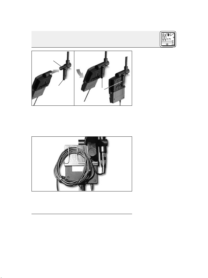
3.1 Mikrofon befestigen ...........................8
3.2 Mikrofon positionieren .........................8
3.3 Weitere Hinweise..............................8
4 Reinigung........................................9
5 Fehlerbehebung .................................10
6 Technische Daten ................................11
2
AKG C 518 M / C 518 ML
Page 3

1.1 Sicherheitshinweis
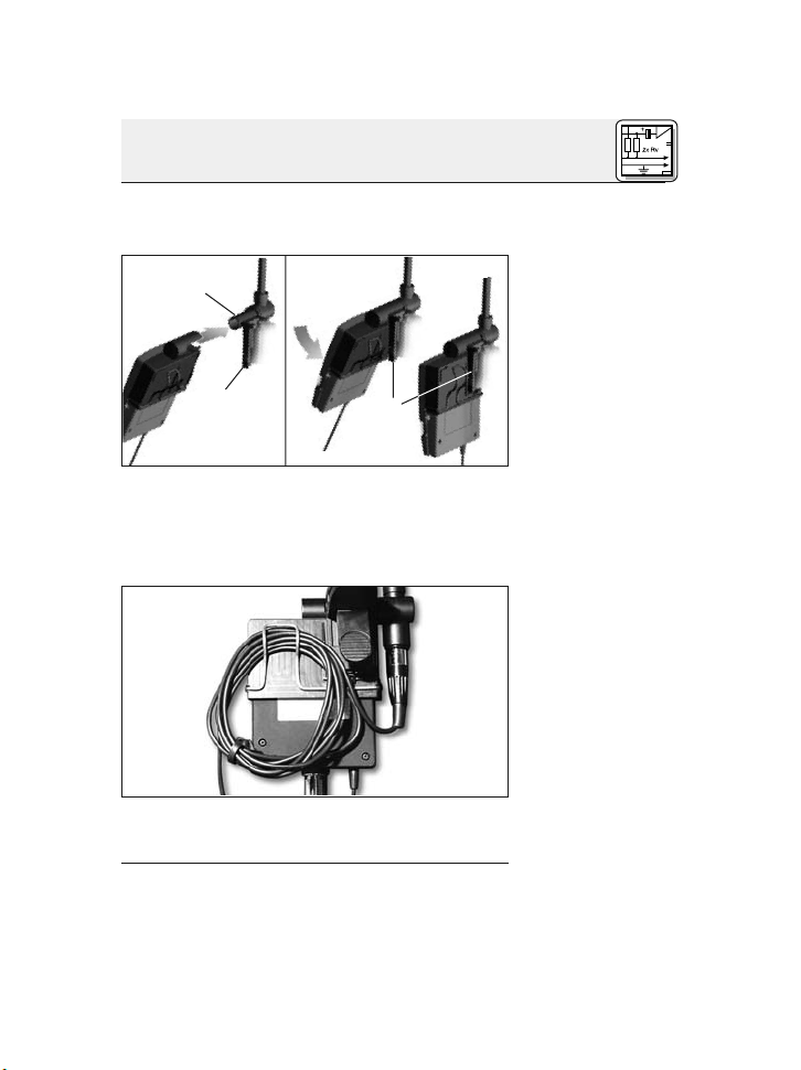
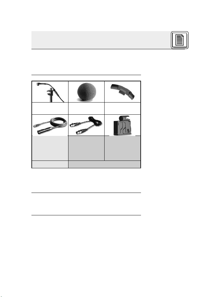
1.2
Lieferumfang
1.3 Optionales
Zubehör
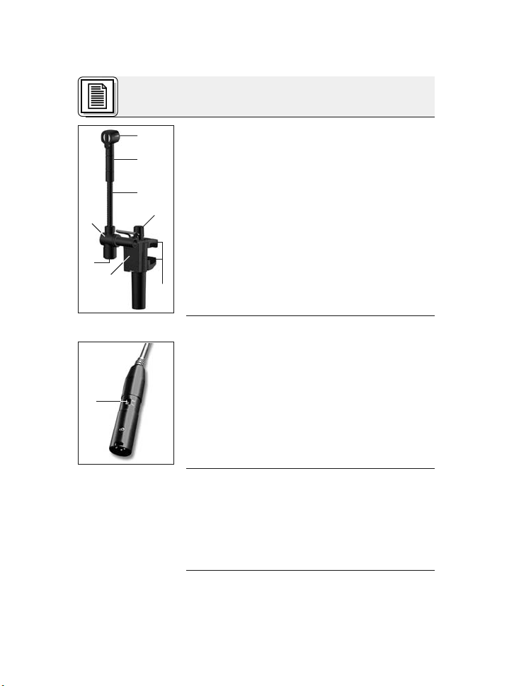
1.4 Kurzbeschreibung
Siehe Abb. 1
auf Seite 4.
Überprüfen Sie bitte, ob das Gerät, an das Sie das
Mikrofon anschließen möchten, den gültigen Si-
cherheitsbestimmungen entspricht und mit einer
Sicherheitserdung versehen ist.
Kontrollieren Sie bitte, ob die Verpackung alle
oben angeführten Teile enthält. Falls etwas fehlt,
wenden Sie sich bitte an Ihren AKG-Händler.
•Siehe www.akg.com oder aktuelle MicroMic-
Broschüre.
•C 518 ML: Batteriespeisegerät B 29 L
1 Mikrofon mit nierenförmiger Richtcharakteristik
für hohe Rückkopplungssicherheit. Frequenzgang speziell für Schlaginstrumente ausgelegt.
2 Elastische Lagerung zur wirkungsvoll
en Unter-
drückung mechanischer Störgeräusche
3 Schwanenhals (50 mm) zur exakten Positionie-
rung des Mikrofons.
4 Schwenkgelenk (135°)
3
AKG C518 M/C 518 ML
1 Sicherheitshinweis/Beschreibung
1 x C 518 1 x W 44
1 x A 518
Fixierungswinkel
1 Verbindungskabel Mini-
XLR/StandardXLR, 3 m lang
1 Verbindungskabel MiniXLR/Mini-XLR,
1.5 m lang
1 Adapter A 400
für Taschensender PT 40 oder
PT 400
Nur C 518 M Nur C 518 ML
Page 4
1 Beschreibung
1.5C518M
1.6C518ML
5 Mini-XLR-Buchse für Anschlusskabel
6 Trägerplatte für Adapter A 400 zum Befestigen
des Taschensenders PT 40 oder PT 400
7 Rändelschraube zum Öffnen und Schließen
der Klemmbacken (8)
8 Klemmbacken zum Befestigen des Mikrofons
am Spannring
Abb. 1: Mikrofon C 518 M/C 518 ML
•Für 9 bis 52 V Universal-Phantomspeisung.
• 3 m langes, steckbares Anschlusskabel mit
Phantomspeiseadapter mit integriertem 3-poligem XLR-Stecker und schaltbarer Bassabschwächung (9)(-4 dB bei 100 Hz).
Abb. 1a: Phantomspeiseadapter mit Bassabschwächungsschalter (9)
•Für Speisung mittels BatteriespeisegerätB29
L, Phantomspeiseadapter MPA V L oder Sender PT 40, PT 400.
• 1,5 m langes, steckbares Anschlusskabel mit
3-poligem Mini-XLR-Stecker.
• Adapter A 400 zum Befestigen des Taschensenders PT 40 oder PT 400
4
AKG C 518 M / C 518 ML
Page 5
2 Anschluss
Das C 518 M/C 518 ML ist ein Kondensatormikrofon und benötigt daher eine Stromversorgung.
Wenn Sie andere als die von AKG empfohlenen
Speisegeräte verwenden, kann das Mikrofon
beschädigt werden und erlischt die Garantie.
1. Verbinden Sie mittels des mitgelieferten Anschlusskabels die Ausgangsbuchse (5) am
Schwanenhals mit einem symmetrischen XLR-
Mikrofoneingang mit Phantomspeisung.
2. Schalten Sie die Phantomspeisung ein. (Lesen
Sie dazu in der Betriebsanleitung des jeweiligen Gerätes nach.)
1. Verbinden Sie mittels des mitgelieferten Anschlusskabels die Ausgangsbuchse (5) am
Schwanenhals mit einer der beiden Mini-XLRBuchsen am B 29 L oder der Mini-XLR-Kupplung am Anschlusskabel des MPA V L.
Der Stecker verriegelt sich automatisch.
• Zum Abziehen des Kabels drücken Sie auf den
Entriegelungsknopf am Mini XLR-Stecker und
ziehen Sie den Stecker aus der Buchse heraus.
•Um das Kabelnichtzubeschädigen,zie-
hen Sie niemals am Kabelselbst!
2. B29L:Verbinden Sie das B 29 L mit dem ge-
wünschten Eingang.
MPA V L: Stecken Sie den MPA V L an einen
symmetrischen XLR-Mikrofoneingang mit
Phantomspeisung an und schalten Sie die
Phantomspeisung ein.
2.1 Einleitung
Wichtig!
2.2C518M
Siehe Abb. 1 auf
Seite 4.
2.3C518ML
2.3.1 B 29 L oder
MPA V L
Kabel abziehen:
Wichtig!
AKG C 518 M / C 518 ML
5
Page 6
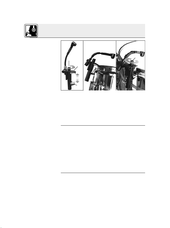
2 Anschluss
2.3.2 Anschluss an
Taschensender
Hinweis:
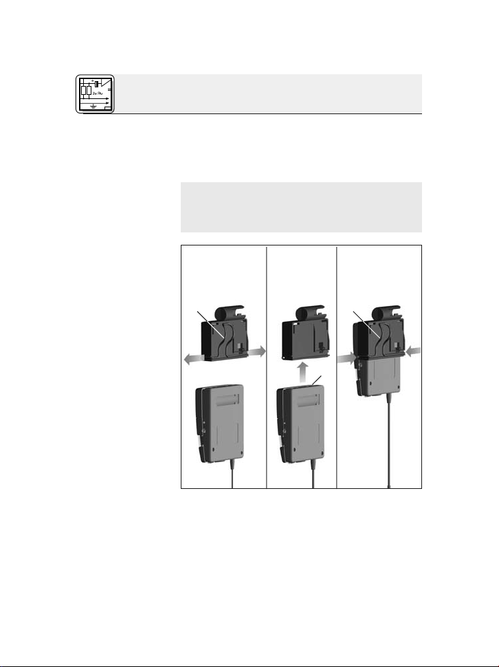
Taschensender
am Mikrofon be-
festigen:
Abb. 2: Taschen-
sender am Adapter
befestigen
Siehe Abb. 2.
6
• Verbinden Sie mittels des mitgelieferten Anschlusskabel die Ausgangsbuchse am Schwanenhals mit der Eingangsbuchse am Taschensender.
• Sie können den Taschensenderam Gürtel oder
am Instrument befestigen. Die Taschensender
PT 40 und PT 400 können Sie auch direkt am
Mikrofon befestigen (siehe unten).
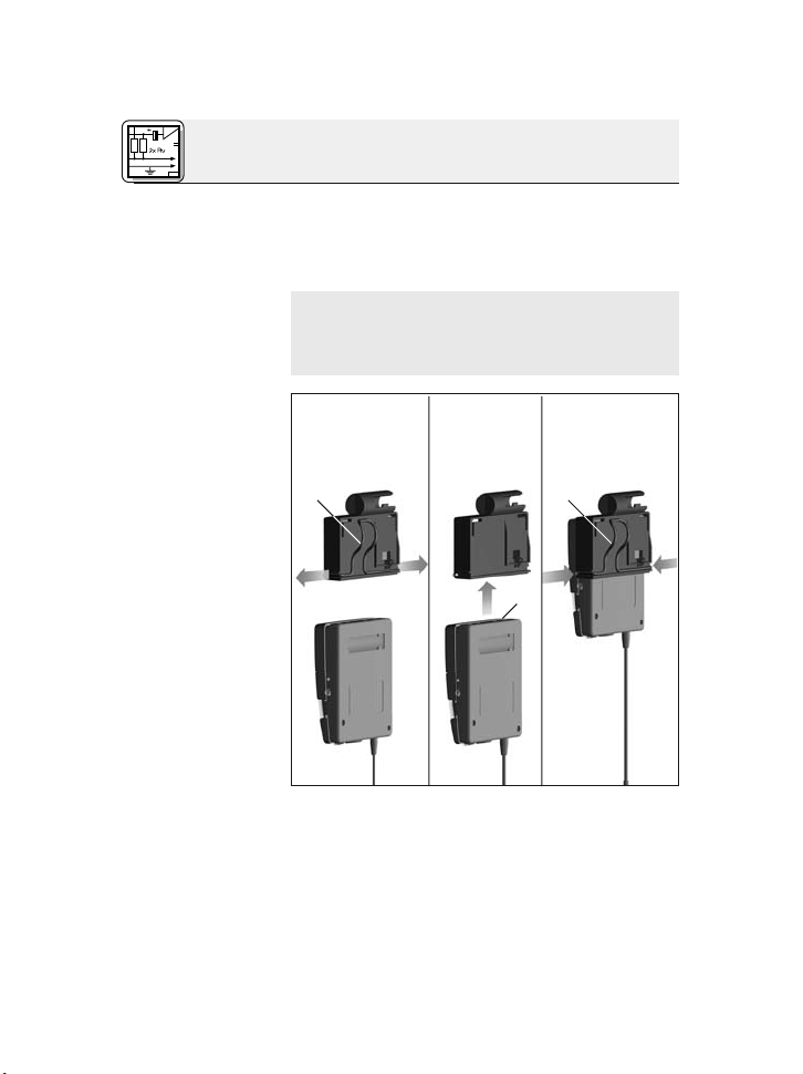
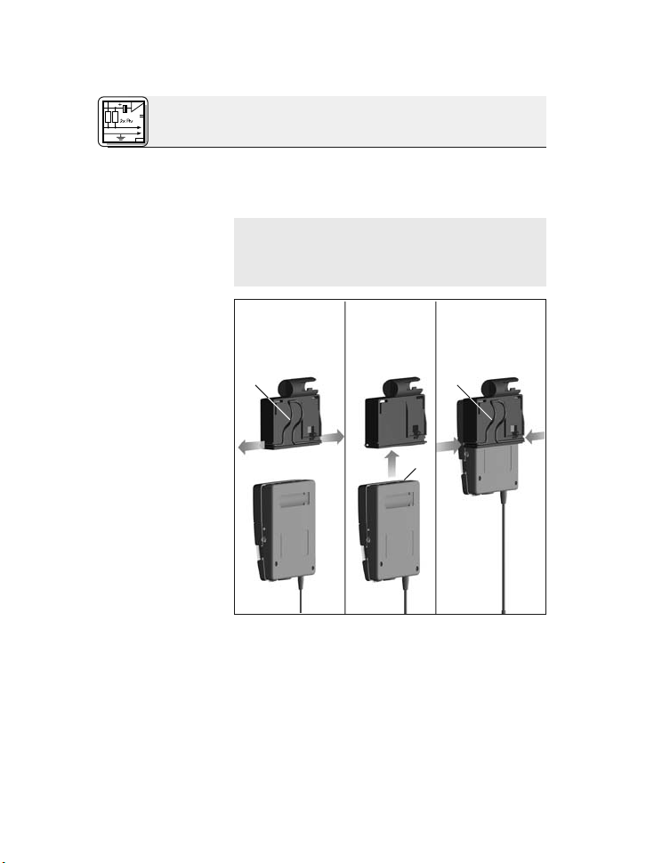
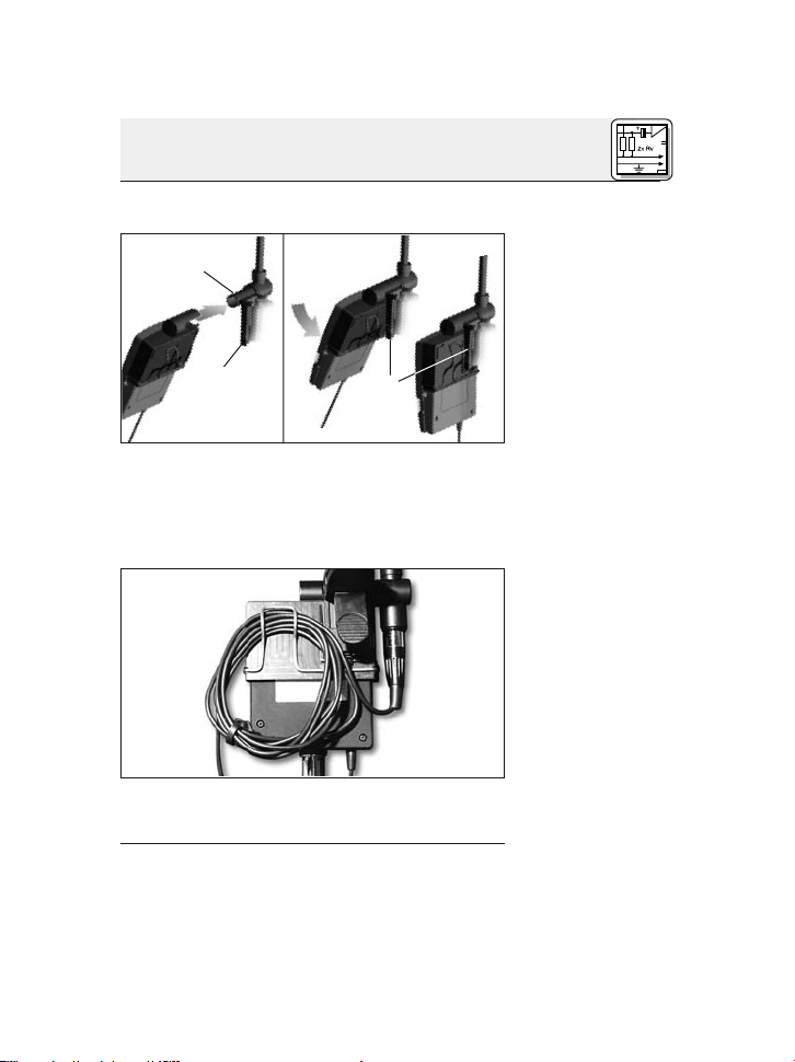
321
1. Ziehen Sie die Enden des Haltebügels (1) aus
dem Adapter heraus.
2. Schieben Sie den Taschensender (2) bis zum
Anschlag in den Adapter hinein.
3. SteckenSie dieEnden des Haltebügels (1) wieder in die Öffnungen im Adapter. Die Enden
des Haltebügels greifen in die Öffnungen im
AKG C 518 M / C 518 ML
Page 7
2 Anschluss
Gehäuse des Taschensenders ein und fixieren
den Taschensender.
4
5
4. Schieben Sie den Adapter mit dem Taschensender auf den Dorn (3) an der Trägerplatte (4).
5. Drücken Sie den Adapter auf die Trägerplatte
(4). Der Adapter rastet hörbar ein.
6
6. Rollen Sie das Anschlusskabel auf und fixieren
Sie es unter dem Haltebügel.
Abb. 3: Adapter
mit Taschensender
am Mikrofon befestigen
Siehe Abb. 3.
Abb. 4: Anschlusskabel aufrollen und
fixieren
Siehe Abb. 4.
AKG C 518 M / C 518 ML
7
Page 8
8
AKG C518 M/C 518 ML
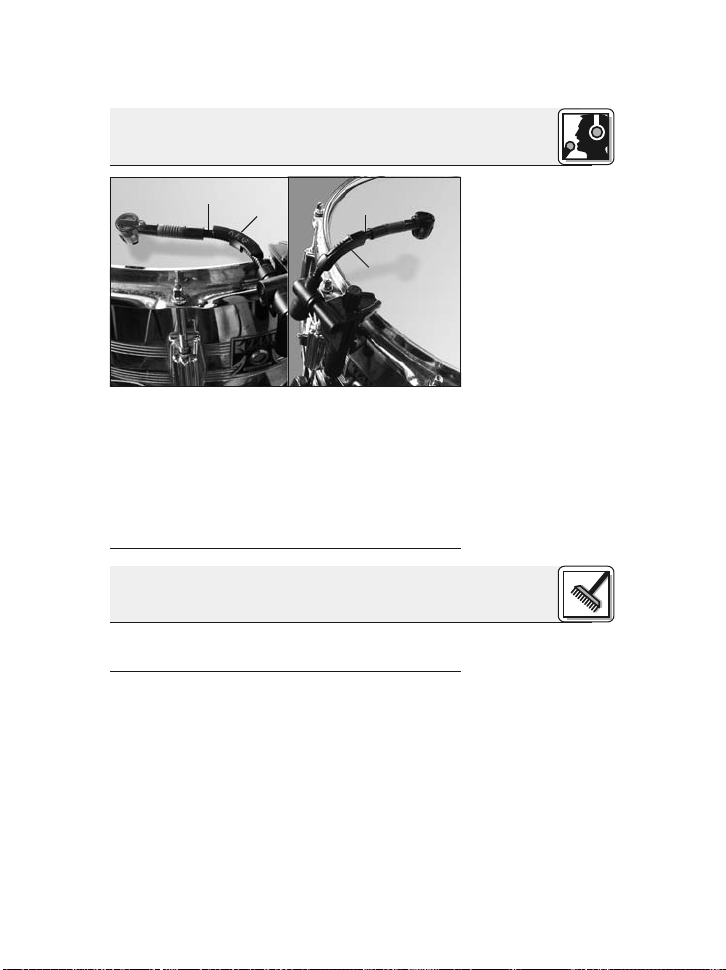
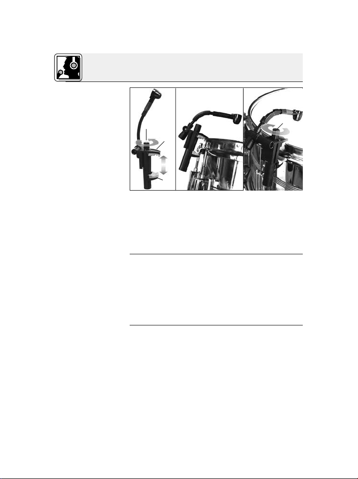
3.1 Mikrofon
befestigen
Abb. 5: Befestigung
des Mikrofons an
Snare Drum,
Tom-Tom oder
Roto-Tom
Siehe Abb. 5.
3.2 Mikrofon
positionieren
3.3 Weitere
Hinweise
Siehe Abb. 6
auf Seite 9.
1. Drehen Sie die Rändelschraube (1) gegen de
n
Uhrzeigersinn, um die Klemmbacken (2) zu öffnen.
2.Hängen Sie das Mikrofon am Spannring der
Trommel ein.
3. Ziehen Sie die Rändelschraube (1) im Uhrzeigersinn fest.
• Wenn Sie das Mikrofon auf den Rand des
Schlagfells ausrichten, erhalten Sie einen harten, knackigen Sound.
• Wenn Sie das Mikrofon auf die Mitte des
Schlagfells ausrichten, erhalten Sie einen vol-
leren, offeneren Sound.
•Einen besonders trockenen Sound erhalten
Sie, wenn Sie ein Papiertaschentuch oder ein
Stück Filz mit Klebeband am Rand des Schlagfells befestigen.
•Bei Tr ommeln mit geringem Durchmesser
empfehlen wir, das Mikrofon am Rand des
Schlagfells zu positionieren, damit der gesamte Spielbereich für die Sticks frei bleibt.
•Um ein Zurückfedern des Schwanenhalses (1)
zu verhindern, können Sie den Fixierungswin-
12 3
3 Anwendung
Page 9
3 Anwendung
a
b
kel (2) horizontal (a) oder vertikal (b) auf den
Schwanenhals aufstecken.
•Um das Nachschwingen des Schlagfells nicht
hörbar werden zulassen, könnenSie am Phantomspeiseadapter die Bassabsenkung einschalten.
4 Reinigung
Reinigen Sie das Gehäuse des Mikrofons mit einem mit Wasser befeuchteten Tuch.
Abb. 6:Fixierungswinkel - a) horizontal, b)vertikal
Nur C 518 M!
AKG C 518 M / C 518 ML
9
Page 10

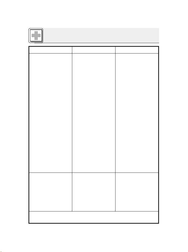
5 Fehlerbehebung
Fehler Mögliche Ursache Abhilfe
Kein Ton: 1. Mischpult und/oder
Verstärker ausgeschaltet.
2. Kanal-Fader oder
Summenpegelregler
am Mischpult oder
Lautstärkeregler des
Verstärkers steht auf
Null.
3. Mikrofon nicht an
Mischpult oder
Verstärker angeschlossen.
4. Kabelstecker nicht
richtig angesteckt.
5. Kabel defekt.
6. Keine Speisespannung.
Verzerrungen: 1. Gain-Regler am
Mischpult zu weit
aufgedreht.
2. Mischpulteingang zu
empfindlich.
1. Mischpult und/oder
Verstärker einschalten.
2. Kanal-Fader oder
Summenpegelregler
am Mischpult oder
Lautstärkeregler des
Verstärkers auf gewünschten Pegel einstellen.
3. Mikrofon an Mischpult oder Verstärker
anschließen.
4. Kabelstecker nochmals anstecken.
5. Kabel überprüfen und
falls nötig ersetzen.
6. Phantomspeisung
einschalten.
Phantomspeisegerät:
ans Netz anschließen
bzw. Batterie(n) einlegen.
Kabel überprüfen und
falls nötig ersetzen.
1. Gain-Regler zurück-
drehen.
2. 10-dB-Vorabschwächung zwischen Mikrofonkabel und Eingang stecken.
C 518 ML: Siehe auch Bedienungsanleitung des Sendersund Empfängers!
10
AKG C 518 M / C 518 ML
Page 11
11
AKG C518 M/C 518 ML
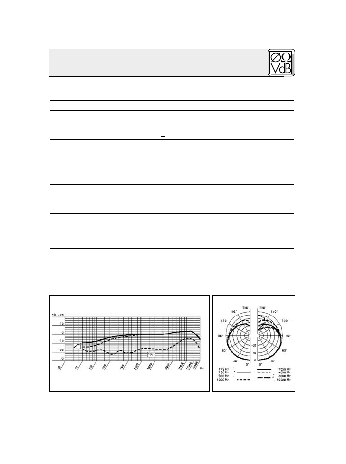
6 Technische Daten
Arbeitsweise: Kondensatorwandler mit Permanentladung
Richtcharakteristik:Niere
Übertragungsbereich: 60 – 20.000 Hz
Empfindlichkeit: 5 mV/Pa (-46 dBV bez. auf 1 V/Pa)
Elektrische Impedanz bei 1000 Hz:<200 Ohm
Empfohlene Lastimpedanz:
>
2000 Ohm
Grenzschalldruck für 1 %/3 % Klirrfaktor: 130 dB/132 dB
Äquivalentschalldruckpegel:31 dB(A) nach DIN 45412
Speisespannung: Batteriespeisegerät B 29 L,
Phantomspeiseadapter MPA V L, AKG
WMS Taschensender
Kabellänge / Steckerart: 1,5 m / Mini-XLR 3-polig
Oberfläche: mattschwarz
Abmessungen (nur Mikrofon): Länge: 200 mm, max. Breite: 47 mm
Nettogewicht (Mikrofon inkl. Kabel): C 518 M: 220 g
C 518 ML: 110 g
Bruttogewicht: C 518 M: 450 g
C 518 ML: 330 g
Dieses Produkt entspricht den in der Konformitätserklärung angeführten
Normen. Sie können die Konformitätserklärung auf http://www.akg.com oder
per E-Mail an sales@akg.com anfordern.
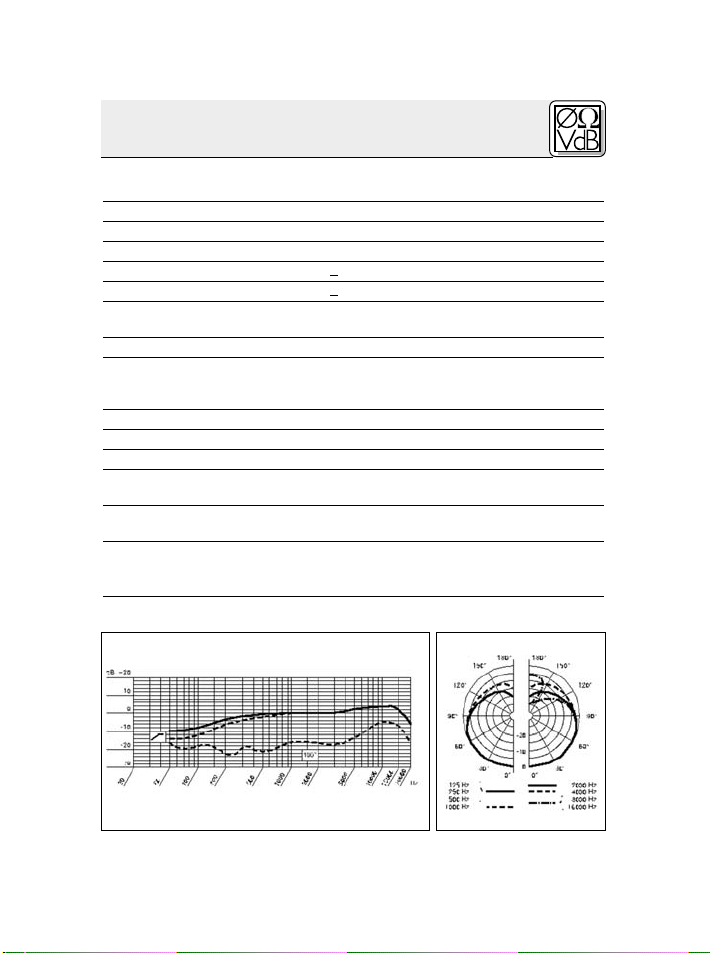
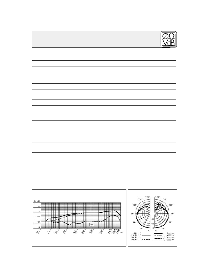
Frequenzgang Polardiagramm
Page 12

Table of Contents
Page
1 Precaution/Description ...........................13
1.1 Precaution..................................13
1.2 Unpacking..................................13
1.3 Optional Accessories .........................13
1.4 Brief Description .............................13
1.5C518M....................................14
1.6C518ML...................................14
2 Interfacing ......................................15
2.1 Introduction.................................15
2.2C518M....................................15
2.3C518ML...................................15
2.3.1 B 29 L or MPA V L........................15
2.3.2 Connecting to a Bodypack Transmitter .......16
3 Using Your Microphone ...........................18
3.1 Mounting the Microphone ......................18
3.2 Aligning the Microphone .......................18
3.3MoreHints..................................18
4 Cleaning........................................19
5 Troubleshooting .................................20
6 Specifications ...................................21
12
AKG C 518 M / C 518 ML
Page 13
1.1 Precaution
1.2 Unpacking
1.3 Optional
Accessories
1.4 Brief
Description
Refer to fig. 1 on
page 14.
Please make sure that the piece of equipment
your microphone will be connected to fulfills the
safety regulations in force in your country and is
fitted with a ground lead.
Check that the packaging contains all of the components listed above. Should anything be missing, please contact your AKG dealer.
• Visit www.akg.com or refer to the latest
MicroMic brochure.
•C 518 ML: B 29 L battery power supply
1 Cardioid microphone for high gain before feed-
back. Frequency response tailored to drum
miking.
2 Shock mount reduces handling and cable
noise.
3 50-mm (2-in.) gooseneck fo
r accurate micro-
phone alignment.
4 Swivel joint (135°).
13
AKG C518 M/C 518 ML
1 Precaution / Description
1 x C 518 1 x W 44
1 x A 518
stabilizer knee
1 x mini XLR to
standard XLR
connecting ca-
ble (10 ft./3 m)
1 x mini XLR to
mini XLR connecting cable
(5 ft./1.5 m)
1 x A 400 adapter for PT 40 or
PT 400 bodypack transmitter
C 518 M only C 518 ML only
Page 14

1 Description
1.5C518M
1.6C518ML
5 Mini XLR output socket for connecting cable.
6 Mounting plate for the A 400 adapter allowing
you to attach a PT 40 or PT 400 bodypack
transmitter.
7 Knurled-head screw for opening and tighten-
ing the clamp jaws (8).
8 Clamp jaws for fixing the microphone on the
top hoop.
Fig. 1: C 518 M/C 518 ML microphone
•For9to52Vuniversal phantom power.
• 10-ft. (3-m) plug-in connecting cable with
phantom power adapter with integrated 3-pin
XLR connector and switchable bass rolloff (9)
(-4 dB at 100 Hz).
Fig. 1a: Phantom power adapter with bass rolloff
switch (9).
•For use with the B 29 L battery power supply,
MPA V L phantom power adapter, or PT 40 or
PT 400 transmitters.
• 5-ft. (1.5-m) plug-in connecting cable with 3pin mini XLR connectors.
• A 400 adapter for attaching a PT 40 or PT 400
bodypack transmitter.
14
AKG C 518 M / C 518 ML
Page 15
2 Interfacing
The C 518 M/C 518 ML is a condenser microphone and therefore needs a power supply.
Using any power supply other than those
recommendedby AKG may damageyour
microphone andwill void the warranty.
1. Use the supplied connecting cable to connect
the output socket (5) on the gooseneck to a
balanced XLR microphone input with phantom
power.
2. Switch the phantom power on. (Refer to the instruction manual of the unit to which you connected your microphone.)
1. Use the supplied connecting cable to connect
the output socket (4) on the gooseneck to one
of the two mini XLR sockets on the B 29 L or
the mini XLR socket on the connecting cable of
the MPA V L.
The connector will lock automatically.
• To disconnect the cable, press the unlocking
button on the mini XLR connector (1) and pull
the connector (1) out of the socket.
• To avoiddamaging the cable, never pull
at the cable itself!
2. B29L:Connect theB 29L to the desired input.
MPA V L: Connect the MPA V L to a balanced
XLR microphone input with phantom power
and switch the phantom power on.
2.1 Introduction
Important!
2.2C518M
Refer to fig. 1.
2.3C518ML
2.3.1 B 29 L
or MPA V L
Disconnecting
the cable:
Important!
AKG C 518 M / C 518 ML
15
Page 16
2 Interfacing
2.3.2 Connecting
to a Bodypack
Transmitter
Note:
Attaching the
Bodypack Trans-
mitter to the Mi-
crophone:
Fig. 2:Inserting the
transmitter into the
adapter.
Refer to fig. 2.
•Use the supplied connecting cable to connect
the output socket on the gooseneck to the input socket on the bodypack transmitter.
• You can attach the bodypack transmitter to
your belt or to the instrument. The PT 40 and
PT 400 bodypack transmitters will also mount
directly on the microphone (see below).
321
1. Pull the ends of the fixing clip (1) out of the
adapter.
2. Slide the transmitter (2) all the way into the
adapter.
3. Reinsert the ends of the fixing clip (1) into the
openings in the adapter. The ends of the fixing
clip engage the locating holes in the transmitter case to hold the transmitter in place.
16
AKG C 518 M / C 518 ML
Page 17

2 Interfacing
4
5
4. Slide the adapter with the transmitter on the
shaft (3) on the mounting plate (4).
5. Press the adapter against the mounting plate
(4). The adapter will lock with an audible click.
6
6. Coil the connecting cable and stow it beneath
the fixing clip.
Fig. 3: Mounting
the adapter and
transmitter on the
microphone.
Refer to fig. 3.
Fig. 4: Coiling and
stowing the connecting cable.
Refer to fig. 4.
AKG C 518 M / C 518 ML
17
Page 18

3 Using Your Microphone
3.1 Mounting the
Microphone
Fig. 5:Fixing the
microphone on a
snare drum, tom-
tom, or Roto tom.
Refer to fig. 5.
3.2 Aligning the
Microphone
3.3MoreHints
C 518 M only!
12 3
1. Turn the knurled-head screw (1) CCW to open
the clamp jaws (2).
2. Hang the microphone on the top hoop of the
drum.
3. Tighten the knurled-head screw (1) CW.
• To get a tight, punchy sound, aim the microphone at the perimeter of the skin.
• To get a rounder, more open sound, aim the microphone at the center of the skin.
• To get a very dry sound, you can tape a strip of
felt or a piece of tissue paper to the skin in an
off-center position.
• When miking up small-diameter drums, we
recommend aiming the microphone at the
perimeter of the top skin to keep the microphone clear of the sticks.
• To keep the ringing of the top skinfrom becoming audible, you can switch in the bass rolloff
on the phantom power adapter.
18
AKG C 518 M / C 518 ML
Page 19

3 Using Your Microphone
a
b
• To prevent the gooseneck (1) from straightening after you bent it, you may snap the stabilizer knee (2) on the gooseneck in a horizontal
(a) or vertical (b) position.
4 Cleaning
To clean the microphone case, use a soft cloth
moistened with water.
Fig. 6: Stabilizer
knee: a) horizontal,
b)vertical orientation.
Refer to fig. 6.
AKG C 518 M / C 518 ML
19
Page 20

5 Troubleshooting
Problem
No sound: 1. Power to mixer
Distortion: 1. Gain control on the
PossibleCause Remedy
and/or amplifier is off.
2. Channel or master
fader on mixer, or vol-
ume control on amplifier is at zero.
3. Microphone is not
connected to mixer
or amplifier.
4. Cable connectors are
seated loosely.
5. Cable is defective.
6. No supply voltage.
mixer set too high.
2. Mixer input sensitivity
too high.
1. Switch power to
mixer or amplifier on.
2. Set channel or master fader on mixer or
volume control on
amplifier to desired
level.
3. Connect microphone
to mixer or amplifier.
4. Check cable connectors for secure seat.
5.
Check cable and replace if damaged.
6. Switch phantom
power on.
Phantom power supply: connect topower
outlet or insert battery
(batteries).
Check cable and replace if necessary.
1. Turn gaincontrol
down CCW.
2. Connect a 10-dB
preattenuation pad
between microphone
cable and input.
20
C 518 ML: Also readthe transmitter and receiver manuals!
AKG C 518 M / C 518 ML
Page 21

6Specifications
Ty pe : pre-polarized condenser microphone
Polar pattern: cardioid
Frequency range: 60 Hz to 20,000 Hz
Sensitivity at 1 kHz: 5 mV/Pa (-46 dBV re 1 V/Pa)
Impedance: ≤ 200 ohms
Recommended load impedance: ≥ 2000 ohms
Max. SPL for 1%/3% THD: 130/132 dB SPL
Equivalent noise level: 31 dB(A) to DIN 45412
Power requirement:
Cable length / Connector: 1.5 m (5 ft.) /3-pin mini XLR
Finish: matte black
Size (microphone only): length: 200 mm (7.9 in.)
Net weight (microphone and cable): C 518 M: 220 g (7.8 oz.)
Shipping weight: C 518 M: 450 g (15.9 oz.)
This product conforms to thestandards listed in the Declarationof Conformity.
To order a free copy of the Declaration of Conformity, visit http://www.akg.com or
contact sales@akg.com.
Frequency Response Polar Diagram
B 29 L battery power supply,
MPA V L phantom adapter,
AKG WMS bodypack transmitters
max. width: 47 mm (1.9 in.)
C 518 ML: 110 g (3.9 oz.)
C 518 ML: 330 g (11.7 oz.)
AKG C 518 M / C 518 ML
21
Page 22

Table des matières
Page
1 Consigne de sécurité / Description ..................23
1.1 Consigne de sécurité .........................23
1.2 Fournitures.................................23
1.3 Accessoires opcionnels .......................23
1.4 Description succincte .........................23
1.5C518M....................................24
1.6C518ML...................................24
2 Raccordement...................................25
2.1 Introduction.................................25
2.2C518M....................................25
2.3C518ML...................................25
2.3.1 B 29 L ou MPA V L .......................25
2.3.2 Raccordement à un émetteur de poche.......26
3 Utilisation.......................................28
3.1 Fixerlemicrophone...........................28
3.2 Positionner le microphone .....................28
3.3 Autres indications ............................28
4 Nettoyage ......................................29
5 Dépannage .....................................30
6 Caractéristiques techniques .......................31
22
AKG C 518 M / C 518 ML
Page 23

1.1 Consigne de
sécurité
1.2 Fournitures
1.3 Accessoires
optionnels
1.4 Description
succincte
Voir Fig. 1,
page 24.
Vérifiez si l’appareil auquel vous voulez raccorder
le microphone répond aux prescriptions relatives
à la sécurité en vigueur et s’il possède une mise à
la terre de sécurité.
Contrôlez si le carton contient bien tous les éléments énumérés ci-dessus. Si ce n’est pas le cas,
veuillez contacter votre distributeur AKG.
• Pour les autres accessoires voir www.akg.com
ou la brochure MicroMic la plus récente.
•C 518 ML: Alimentation batterie B 29 L
1 Microphone à caractéristique cardioïde pour
une haute protection contre le larsen. Réponse
en fréquence spécialement adaptée pour l’accordéon, les amplificateurs de guitar
e et de
basse et le piano.
2 Suspension élastique pour suppression efficace
des bruits mécaniques
3 Col-de-cygne de 50 mm permettant de posi-
23
AKG C518 M/C 518 ML
1 Consigne de sécurité / Description
1 x C 518 1 x W 44
1 A 518 équerre
de fixation
1 câble de liaison
mini-XLR/XLR
standard, 3 m de
long
1 câble de liaison
mini-XLR/miniXLR, 1,5 m de
long
1 Adaptateur
A 400 pour émetteur de poche
PT 40 ou PT 400
C 518 M seulement
C 518 ML seulement
Page 24

1 Description
1.5C518M
C518ML
tionner le micro avec une grande précision.
4 Articulation pivotante (135°)
5 Prise mini-XLR pour câble de raccordement
6Plaque support pour adaptateur A400 permet-
tantdefixer l’émetteur de poche PT 40 ou
PT 400
7 Molette pour ouvrir et fermer les mors (8)
8 Mors de fixation du microphone sur le cercle
Fig. 1: Microphone C 518 M/C 518 ML
• Pour alimentation fantôme universelle de 9 à
52 V.
• Câble de raccordement de 3 m de long
connectable avec adaptateur pour alimentation fantôme, avec connecteur XLR à 3 points
et atténuation des graves commutable (9)
(-4dBà100Hz).
Fig. 1a: Adaptateur pour alimentation fantôme
avec commutateur d’atténuation des graves (9)
• Pour alimentation par boîtier à pile B 29 L, mo-
dule d’alimentation fantôme MPA V L ou émetteur de poche PT 40 ou PT 400.
• Câble de raccordement enfichable de 1,5 mde
long, avec connecteur mini-XLR 3 points.
• Adaptateur A 400 pour la fixation de l’émetteur
de poche PT 40 ou PT 400
24
AKG C 518 M / C 518 ML
Page 25

2 Raccordement
Le C 518 M/C 518 ML est un microphone électrostatique ; il a donc besoin d’une alimentation.
L’ utilisation d’alimentations autres que
cellesrecommandées par AKG peut provo-
quer des dégâtssurlemicroetentraîne la
perte de la garantie.
1. Reliez l’embase de sortie (5) du col de cygne
sur une entrée micro symétrique XLR avec ali-
mentation fantôme à l’aide du câble de raccordement fourni.
2. Mettez l’alimentation fantôme sous tension
(Veuillez vous reporter à la notice de l’équipement utilisée).
1. A l’aide du câble de raccordement fourni,
connectez la prise de sortie (5) du col-decygne sur une des deux prises mini-XLR du
B 29 L ou sur le connecteur mini-XLR femelle
du câble de raccordement du MPA V L.
Le connecteur se verrouille automatiquement.
• Pour détacher le câble, appuyez sur le bouton
de déverrouillage du connecteur mini-XLR(1)
et sortez le connecteur de la prise.
• Pour ne pas risquer d’abîmerlecâble, ne
sortez jamais leconnecteur en tirant sur
lecâble.
2. B29L:Raccordez le B 29 Lsur l’entrée voulue.
MPA V L: Connectezle MPAVLsuruneentrée
de micro symétrique type
tion fantôme et mettez l’alimentation fantôme
sous tension.
XLR avec alimenta-
2.1 Introduction
Important!
2.2C518M
Voir Fig. 1,
page 24.
2.3C518ML
2.3.1 B 29 L ou
MPA V L
Débrancher le
câble :
Important!
AKG C 518 M / C 518 ML
25
Page 26

2 Raccordement
2.3.2 Raccorde-
ment à un émet-
teur de poche
Remarque:
Comment fixer
l’émetteur de
poche sur le mi-
crophone :
Fig. 2 : Comment
fixer l’émetteur
de poche sur
l’adaptateur
Voir Fig. 2.
26
• Al’aide du câble de raccordement fourni,
connectez la prise de sortie du col-de-cygne
sur la prise d’entrée de l’émetteur de poche.
• Vous pouvez fixer l’émetteur de poche à votre
ceinture ou à l’instrument. Les émetteurs de
poche PT 40 et PT400 peuvent également être
fixés directement sur le micro (voir ci-dessous).
321
1. Extrayez les extrémités de l’étrier (1) de l’adap-
tateur.
2. Enfoncez l’émetteur de poche (2) dans l’adap-
tateur jusqu’en butée.
3. Réintroduisez les extrémités de l’étrier (1) dans
les trous de l’adaptateur. Les extrémités de
l’étrier s’enclenchent dans les ouvertures du
boîtier de l’émetteur qui se trouve ainsi fixé.
AKG C 518 M / C 518 ML
Page 27

2 Raccordement
4
5
4. Glissez l’adaptateur avec l’émetteur de poche
sur l’ergot (3) de la plaque support (4).
5. Pressez l’adaptateur contre la plaque support
(4).L’enclenchement est audible.
6
6. Enroulez le câble de raccordement et fixez-le
sous l’étrier.
Fig. 3 : Comment
fixer l’adaptateur
avec l’émetteur de
poche sur le microphone
Voir Fig. 3.
Fig. 4 : Enrouler et
fixer le câble de
raccordement
Voir Fig. 4.
AKG C 518 M / C 518 ML
27
Page 28

3 Utilisation
3.1 Fixation du
microphone
Fig. 5 :Fixation du
micro sur la caisse
claire, le tom-tom
ou roto-tom
Voir Fig. 5.
3.2 Positionner
lemicrophone
3.3 Autres
indications
12 3
1. Tournez lamolette (1) dans le sens inverse de la
montre pour ouvrir les mors (2).
2. Suspendez le microphone au cercle du tambour.
3. Resserrez la molette (1) en tournant dans le
sens de la montre.
• En orientant le micro vers le bord de la membrane de percussion, vous obtenez un son
ferme, incisif.
• En orientant le micro vers le centre de la membrane de percussion, vous obtenez un son
plein, plus moelleux.
• Pour obtenir un son très sec, vous pouvez fixer
àl’aide d’un ruban adhésif un morceau de ser-
viette en papier ou de feutre sur le bord de la
membrane de percussion.
• Sur les tambours de petit diamètre, positionnez le microphone au bord de la membrane de
manière à ne pas gêner la frappe des
mailloches.
28
AKG C 518 M / C 518 ML
Page 29
3 Utilisation
a
b
• Pour éviter un effet de ressort du col de cygne
(1)vous pouvez placer l’équerre (2) horizonta-
lement (a) ou verticalement (b) sur le col-de-
cygne.
• Si vous ne souhaitez pas que l’on entende la
résonance de la membrane, vous pouvez mettre en service l’atténuateur de graves de
l’adaptateur pour alimentation fantôme.
4 Nettoyage
Le boîtierdu microse nettoie avec un chiffon légè-
rement humide (eau claire).
Fig. 6: Equerre de
fixation - a) horizontale, b)verticale
Voir Fig. 6.
C 518 M seulement!
AKG C 518 M / C 518 ML
29
Page 30
5Dépannage
Problème
Pasdeson: 1. La console de mixage
Distorsions : ble de mixage est trop
C 518 ML : Veuillez vous reporter aussi aux notices d’emploi
Cause possible Remède
et/ou l’amplificateur ne
sont pas sous tension.
2. Le fader du canal ou le réglagedeniveau master de la
console de mixage ou le
réglage de niveau sonore
de l’ampli est sur zéro.
3. Le micro n’est pas con-
necté à la console de mixage ou à l’ampli.
4. La fiche est mal enfoncée.
5. Le câble est abîmé.
6. Pas de tension d’alimentation.
1. Le réglage de gain de la ta-
haut.
2. L’entrée de la table de mixage est trop sensible.
de l’émetteur et du récepteur !
1. Mettre la console de mixage et/ou l’amplificateur
sous tension.
2. Régler le fader du canal ou
le réglage de niveau master de la console de mi-
xage ou le réglage de niveau sonore de l’ampli sur
la valeur voulue.
3. Connecter le micro à la
console de mixage ou à
l’ampli.
4. Enfoncer la fiche correctement.
5. Contrôler le câble et le
remplacer le cas échéant.
6. Mettre l’alimentation fantôme sous tension.
Appareil d’alimentation
fantôme : brancher sur le
secteur ou mettre une (des)
pile(s).
Contrôler le câble et le
remplacer le cas échéant.
1. Baisser le réglage de gain.
2. Insérer un pré-atténuateur
de sensibilité entre le câble
du micro et l’entrée.
30
AKG C 518 M / C 518 ML
Page 31
31
AKG C518 M/C 518 ML
6 Caractéristiques techniques
Fonctionnement: microphone électrostatique à charge per-
manente
Directivité:cardioïde
Réponse en fréquence: 60 … 20.000 Hz
Sensibilité :5 mV/Pa (-46 dBV rapp. à 1 V/Pa)
Impédance électrique à 1.000 Hz:<200 ohms
Impédance de charge recommandée:>2000 ohms
Niveau maximum de pression sonore pour un facteur
de distorsion de 1% / 3%: 130 / 132 dB SPL
Niveau de bruit équivalent: 31 dB(A) selon DIN 45412
Tension d’alimentation:alimentation à piles B 29 L,
adaptateur fantôme MPA V L,
émetteurs de poche AKG WMS
Longueur du câble / Connecteur: 1,5 m / type mini-XLR, 3 points
Couleur: noir mat
Dimensions (micro seulement): longueur : 200 mm, largeur maxi.: 47 mm
Poids net (micro et câble) : C 518 M: 220 g
C 518 ML: 110 g
Poids brut : C 518 M: 450 g
C 518 ML: 330 g
Ce produit est conforme aux normes citées dans la Déclaration de Conformité,
dont vous pouvez prendre connaissance en consultant le site
http://www.akg.com ou en adressant un
e-mail à sales@akg.com.
Réponse en fréquence Diagramme polaire
Page 32

Indice
Pagina
1 Indicazione per la sicurezza / Descrizione . . . . . . . . . . . . 33
1.1 Indicazione per la sicurezza . . . . . . . . . . . . . . . . . . . . 33
1.2 In dotazione . . . . . . . . . . . . . . . . . . . . . . . . . . . . . . . . 33
1.3 Accessori opzionali. . . . . . . . . . . . . . . . . . . . . . . . . . . 33
1.4 Breve descrizione . . . . . . . . . . . . . . . . . . . . . . . . . . . . 33
1.5 C 518 M. . . . . . . . . . . . . . . . . . . . . . . . . . . . . . . . . . . . 34
1.6 C 518 ML. . . . . . . . . . . . . . . . . . . . . . . . . . . . . . . . . . . 34
2 Collegamento . . . . . . . . . . . . . . . . . . . . . . . . . . . . . . . . . . . 35
2.1 Introduzione . . . . . . . . . . . . . . . . . . . . . . . . . . . . . . . . 35
2.2 C 518 M. . . . . . . . . . . . . . . . . . . . . . . . . . . . . . . . . . . . 35
2.3 C 518 ML. . . . . . . . . . . . . . . . . . . . . . . . . . . . . . . . . . . 35
2.3.1 B 29 L o MPA V L . . . . . . . . . . . . . . . . . . . . . . . . 35
2.3.2 Collegamento ad un trasmettitore da tasca . . . . 36
3 Impiego . . . . . . . . . . . . . . . . . . . . . . . . . . . . . . . . . . . . . . . . 38
3.1 Come fissare il microfono . . . . . . . . . . . . . . . . . . . . . . 38
3.2 Come posizionare il microfono . . . . . . . . . . . . . . . . . . 38
3.3 Ulteriori indicazioni . . . . . . . . . . . . . . . . . . . . . . . . . . . 38
4 Pulizia. . . . . . . . . . . . . . . . . . . . . . . . . . . . . . . . . . . . . . . . . . 39
5 Eliminazione di difetti . . . . . . . . . . . . . . . . . . . . . . . . . . . . . 40
6 Dati tecnici. . . . . . . . . . . . . . . . . . . . . . . . . . . . . . . . . . . . . . 41
32
AKG C 518 M / C 518 ML
Page 33

1.1 Indicazione
per la sicurezza
1.2 In dotazione
1.3 Accessori
opzionali
1.4 Breve
descrizione
Vedi fig. 1
a pagina 34.
Controllate per favore se l’apparecchio che volete
collegare al microfono corrisponde alle norme di
sicurezza vigenti e se è dotato di una messa a
terra di sicurezza.
Controllate per favore se la confezione contiene
tutti i componenti di cui sopra. Se manca qual-
cosa rivolgetevi al vostro rivenditore AKG.
• Alimentatore a batteria B 29 L
• Per altri accessori vedi www.akg.com o l’attuale depliant MicroMic.
1 Microfono a direttività cardioide per alta sicu-
rezza contro il feedback. Risposta in frequenza
ideata specialmente per strumenti di percus-
sione.
2 Supporto elastico
per efficiente soppressione
dei rumori meccanici disturbanti.
3 Collo di cigno lungo 50 mm per il posiziona-
mento esatto del microfono.
33
AKG C518 M/C 518 ML
1 Indicazione per la sicurezza / Descrizione
1 x C 518 1 x W 44
1 x A 518 angolo
di fissaggio
1 cavo di collegamento miniXLR/XLR stan-
dard, lungo 3 m
1 cavo miniXL/mini-XLR,
lungo 1,5 m
1 adattatore
A 400 per trasmet-
titore da tasca
PT 40 o PT 400
Solo per il C 518 M Solo per il C 518 ML
Page 34

1 Descrizione
1.5 C 518 M
C 518 ML
4 Giunto girevole (135°)
5 Presa mini-XLR per cavi di collegamento.
6 Piastra base per l’adattatore A 400 per fissare il
trasmettitore da tasca PT 40 o PT 400.
7 Vite zigrinata per aprire e chiudere le ganasce
(8)
8 Ganasce per fissare il microfono sull’anello
tenditore
Fig. 1: Microfono C 518 M/C 518 ML
• Per alimetazione phantom universale da 9 a 52 V.
• Cavo di collegamento lungo 3 m, innestabile,
con adattatore per alimentazione phantom con
connettore XLR a 3 poli integrato e attenuazione dei bassi regolabile (9) (-4 dB a 100 Hz).
Fig. 1a: Adattatore per alimentazione phantom
con interruttore per l’attenuazione dei bassi (9)
• Per alimentazione mediante alimentatore a
batterie B 29 L, adattatore per alimentazione
phantom MPA V L oppure trasmettitore da tasca PT 40 o PT 400.
• Cavo di collegamento lungo 1,5 m, innestabile,
con connettore mini-XLR a 3 poli.
• Adattatore A 400 per fissare il trasmettitore da
tasca PT 40 o PT 400.
34
AKG C 518 M / C 518 ML
Page 35

2.1 Introduzione
Importante!
2.2 C 518 M
Vedi fig. 1,
pagina 34.
2.3 C 518 ML
2.3.1 B 29 L
o MPA V L
Sfilare il cavo:
Importante!
Il C 518 M/C 518 ML è un microfono a condensatore e ha quindi bisogno di alimentazione.
Se usate alimentatori diversi da quelli raccomandati dall’AKG, il microfono può subire
danni e la garanzia si estingue.
1. Collegate la presa d’uscita (5) disposta sul
collo di cigno ad un ingresso microfonico XLR
simmetrico con alimentazione phantom, ser-
vendovi del cavo di collegamento in dotazione.
2. Inserite l’alimentazione phantom. (Leggete in
merito le istruzioni per l’uso del rispettivo apparecchio.)
1. Collegate la presa d’uscita (5) disposta sul
collo di cigno ad una delle due prese mini-XLR
disposte sul B 29 L o all’accoppiamento miniXLR disposto sul cavo di collegamento del
MPA V L, servendovi del cavo di collegamento
in dotazione.
• Per s filare il cavo, premete il bottone di sblocco
sul connettore mini-XLR (1) e sfilate il connet-
tore (1) dalla presa.
• Per non danneggiare il cavo, non esercitate mai trazione direttamente sul cavo!
2. B 29 L: Collegate il B 29 L (con l’ingresso prescelto.
MPA V L: Collegate l’MPA V L a un ingresso mi-
crofonico XLR simmetrico con alimentazione
phantom e inserite l’alimentazione phantom.
35
AKG C518 M/C 518 ML
2 Collegamento
Page 36
2 Collegamento
2.3.2 Collega-
mento ad un tra-
smettitore da
tasca
Avvertenza:
Come fissare il
trasmettitore da
tasca sul micro-
fono:
Fig. 2: Come fis-
sare il trasmettitore
da tasca
sull’adattatore
Vedi fig. 2.
36
• Collegate la presa d’uscita disposta sul collo di
cigno alla presa d’ingresso del trasmettitore da
tasca servendovi del cavo di collegamento in
dotazione.
Potete fissare il trasmettitore da tasca sulla cintura
o sullo strumento. I trasmettitori da tasca PT 40 e
PT 400 possono venir fissati anche direttamente
sul microfono.
321
1. Sfilate le estremità dell’archetto di fissaggio (1)
dall’adattatore.
2. Infilate il trasmettitore da tasca (2) nell’adatta-
tore fino all’arresto.
3. Reinfilate le estremità dell’archetto di fissaggio
(1) nelle aperture disposte sull’adattatore. Le
estremità dell’archetto di fissaggio rientrano
AKG C 518 M / C 518 ML
Page 37

2 Collegamento
nelle aperture disposte sulla scatola del trasmettitore fissando in tal modo il trasmettitore.
4
5
4. Infilate l’adattatore con il trasmettitore sulla
spina (3) disposta sulla piastra base (4).
5. Premete l’adattatore sulla piastra base (4).
L’adattatore scatta udibilmente.
6
6. Arrotolate il cavo di collegamento e fissatelo
sotto l’archetto di fissaggio.
Fig. 3: Come fissare l’adattatore
con il trasmettitore
sul microfono
Vedi fig. 3.
Fig. 4: Come arrotolare e fissare il
cavo di collegamento
Vedi fig. 4.
AKG C 518 M / C 518 ML
37
Page 38
3 Impiego
3.1 Come fissare
il microfono
Fig. 5: Fissaggio
del microfono sullo
snare drum, tom-
tom o roto-tom
Vedi fig. 5.
3.2 Come
posizionare il
microfono
3.3 Ulteriori
indicazioni
Solo per il C 518 M!
12 3
1. Girate la vite zigrinata (1) in senso antiorario per
aprire le ganasce (2).
2. Fissate il microfono sull’anello tenditore del
tamburo.
3. Serrate la vite zigrinata (1) girandola in senso
orario.
• Puntando il microfono sul margine della pelle,
avrete un sound duro e grintoso.
• Puntando il microfono sul centro della pelle,
avrete un sound più pieno e più aperto.
• Avrete un sound particolarmente asciutto se fissate un fazzoletto di carta o un pezzo di feltro con
un nastro adesivo sul margine della pelle.
• Per i tamburi dal diametro piccolo raccomandiamo di posizionare il microfono sul margine
della pelle per far rimanere libera l’intera zona
di percussione per le bacchette.
• Per non far sentire le riverberazioni della pelle,
potete attivare l’attenuazione dei bassi disposta
sull’adattatore per l’alimentazione phantom.
38
AKG C 518 M / C 518 ML
Page 39

3 Impiego
a
b
• Per evitare che il collo di cigno (1) rimbalzi, potete infilare l’angolo di fissaggio (2) sul collo di
cigno in direzione orizzontale (a) o verticale (b).
Pulite la scatola del microfono con un panno inumidito con acqua.
Fig. 6: Angolo di
fissaggio a) orizzontale,
b) verticale
Vedi fig. 6.
4 Pulizia
AKG C 518 M / C 518 ML
39
Page 40

5 Eliminazione di difetti
Difetto Possibili cause Rimedio
Nessun suono: 1. Mixer e/o amplificatore
sono dis inseriti.
2. Fader del canale o regolatore principale del mixer
o regolatore del volume
dell’amplificatore sono in
posizione zero.
3. Il microfono non è collegato al mixer o all’amplificatore.
4. Il connettore del cavo
non è inserito bene.
5. Il cavo è difettoso.
6. Non c’è alimentazione.
Distorsioni: 1. Il regolatore gain sul mi-
xer è aperto troppo.
2. L’ingresso del mixer è
troppo sensibile.
C 518 ML: Vedi anche le istruzioni per l’uso per il trasmettitore e del ricevitore!
1. Inserire il mixer e/o l’am-
plificatore.
2. Portare al livello deside-
rato il fader del canale o il
regolatore principale del
mixer o il regolatore del
volume dell’amplificatore.
3. Collegare il microfono al
mixer o all’amplificatore.
4. Inserire di nuovo il con-
nettore del cavo.
5. Controllare il cavo e sostituirlo se necessario.
6. Inserire l’alimentazione
phantom.
Alimentatore phantom:
collegarlo alla rete oppure inserire batteria(e).
Controllare il cavo e, se
necessario, sostituirlo.
1. Portare indietro il regolatore gain.
2. Inserire un preattenuatore
di 10 dB tra cavo microfonico ed ingresso.
40
AKG C 518 M / C 518 ML
Page 41
6 Dati tecnici
Modo di funzionamento: microfono a condensatore con carica per-
Direttività: cardioide
Risposta in frequenza: 60 - 20.000 Hz
Sensibilità: 5 mV/Pa (-46 dBV rif. a 1 V/Pa)
Impedenza elettrica a 1000 Hz: ≤ 200 ohm
Impedenza di carico raccomandata: ≥ 2000 ohm
Livello di pressione acustica limite per un coefficiente di
distorsione armonica di 1% / 3%: 130 / 132 dB SPL
Livello di pressione acustica equivalente: 31 dB(A) secondo DIN 45412
Tensione di alimentazione: alimentatore a batterie B 29 L, adattatore
Lunghezza del cavo / connettore: 1,5 m / mini-XLR a 3 poli
Superficie: nero opaco
Dimensioni (microfono): lunghezza: 200 mm
Peso netto (microfono e cavo): C 518 M: 220 g
Peso lordo: C 518 M: 450 g
Questo prodotto corrisponde alle norme elencate nella dichiarazione di conformità, che è disponibile al sito http://www.akg.com oppure all'indirizzo email
sales@akg.com.
manente
phantom MPA V L, trasmettitori da tasca
AKG WMS
larghezza mass.: 47 mm
C 518 ML: 110 g
C 518 ML: 330 g
Risposta in frequenza Diagramma polare
AKG C 518 M / C 518 ML
41
Page 42

Indice
Página
1 Indicaciones de seguridad / Descripción . . . . . . . . . . . . . 43
1.1 Indicaciones de seguridad . . . . . . . . . . . . . . . . . . . . . 43
1.2 Volumen de suministros . . . . . . . . . . . . . . . . . . . . . . . 43
1.3 Accesorios opcionales . . . . . . . . . . . . . . . . . . . . . . . . 43
1.4 Breve descripción. . . . . . . . . . . . . . . . . . . . . . . . . . . . 43
1.5 C 518 M. . . . . . . . . . . . . . . . . . . . . . . . . . . . . . . . . . . . 44
1.6 C 518 ML. . . . . . . . . . . . . . . . . . . . . . . . . . . . . . . . . . . 44
2 Conexión . . . . . . . . . . . . . . . . . . . . . . . . . . . . . . . . . . . . . . . 45
2.1 Introducción . . . . . . . . . . . . . . . . . . . . . . . . . . . . . . . . 45
2.2 C 518 M. . . . . . . . . . . . . . . . . . . . . . . . . . . . . . . . . . . . 45
2.3 C 518 ML. . . . . . . . . . . . . . . . . . . . . . . . . . . . . . . . . . . 45
2.3.1 B 29 L ó MPA V L . . . . . . . . . . . . . . . . . . . . . . . . 45
2.3.2 Conexión a un transmisor de bolsillo . . . . . . . . . 46
3 Utilización . . . . . . . . . . . . . . . . . . . . . . . . . . . . . . . . . . . . . . 48
3.1 Fijar el micrófono. . . . . . . . . . . . . . . . . . . . . . . . . . . . . 48
3.2 Posicionar el micrófono . . . . . . . . . . . . . . . . . . . . . . . 48
3.3 Otras indicaciones . . . . . . . . . . . . . . . . . . . . . . . . . . . 48
4 Limpieza. . . . . . . . . . . . . . . . . . . . . . . . . . . . . . . . . . . . . . . . 49
5 Eliminación de fallos . . . . . . . . . . . . . . . . . . . . . . . . . . . . . . 50
6 Datos técnicos . . . . . . . . . . . . . . . . . . . . . . . . . . . . . . . . . . 51
42
AKG C 518 M / C 518 ML
Page 43

1.1 Indicaciones
de seguridad
1.2 Volumen de
suministro
1.3 Accesorios
opcionales
1.4 Breve
descripción
Véase Fig 1,
página 44.
Sírvase verificar si el aparato al cual quiere conectar el micrófono cumple con las disposiciones de
seguridad vigentes y está equipado con una toma
de tierra de seguridad.
Sírvase controlar si el embalaje contiene todas las
piezas indicadas arriba. Si falta algo, le rogamos
dirigirse a su distribuidor AKG.
•Sírvase consultar www.akg.com o el más re-
ciente folleto sobre MicroMic.
•C 518 ML: Alimentador de pilas B 29 L
1 Micrófono con característica direccional car-
dioide para mayor seguridad contra realimen-
tación acústica. Respuesta de frecuencia dimensionada especialmente para instrumen
tos
de percusión.
2 Alojamiento elástico para eficaz represión de
ruidos perturbadores.
43
AKG C518 M/C 518 ML
1 Indicaciones de seguridad/Descripción
1 x C 518 1 x W 44
1 x A 518
Ángulo de fijación
1 Cable de conexión mini-XLR/
XLR estándar,
3 m de largo
1 Cable de conexión miniXLRmini-XLR,
1,5 m de largo
1 Adaptador
A 400 para trans-
misor de bolsillo
PT 40 ó PT 400
Sólo para C 518 M Sólo para el C 518 ML
Page 44

1 Descripción
1.5 C 518 M
1.6 C 518 ML
3 Cuello de cisne de 50 mm para posicionar el
micrófono con exactitud.
4 Articulación giratoria (135°)
5 Toma mini-XLR para el cable de conexión.
6 Placa portadora para el adaptador A 400 para
fijar el transmisor PT 40 ó PT 400.
7 Tornillo moleteado para abrir y cerrar las mor-
dazas de sujeción (8)
8 Mordazas de sujeción para fijar el micrófono
en el anillo tensor
Fig. 1: Micrófono C 518 M/C 518 ML
•
Para alimentación fantasma universal de 9 a 52 V.
• Cable de conexión enchufable de 3 m de largo
con adaptador de alimentación fantasma y co-
nector XLR de 3 polos integrado y atenuación de
bajos conmutable (9) (-4 dB en 100 Hz).
Fig. 1a: Adaptador de alimentación fantasma con
conmutador de atenuación de bajos (9)
• Para alimentación por medio del alimentador
por batería B 29 L, un adaptador de alimentación fantasma MPA V L o un transmisor de bolsillo PT 40 ó PT 400.
• Cable de conexión enchufable de 1,5 m de
largo con conector mini-XLR de 3 polos.
• Adaptador A 400 para fijar el transmisor de
bolsillo PT 40 ó PT 400.
44
AKG C 518 M / C 518 ML
Page 45
2 Conexión
El C 518 M/C 518 ML es un micrófono de condensador y necesita, por lo tanto, alimentación de corriente.
Si se utilizan alimentadores diferentes a los recomendados por AKG puede dañarse el micrófono, cesando con ello la garantía.
1. Mediante el cable de conexión suministrado
conecte la toma de salida (5) en el cuello de
cisne con una entrada de micrófono XLR ba-
lanceada con alimentación fantasma.
2. Concecte la alimentación fantasma (consulte
para ello el Modo de empleo del aparato correspondiente).
1. Mediante el cable de conexión suministrado
conecte la toma de salida (5) del cuello de
cisne a una de las dos tomas mini-XLR del
B 29 L o al acoplamiento mini-XLR del cable de
conexión del MPA V L.
El conector macho queda automáticamente
bloqueado.
• Para desconectar el cable, presione el desbloqueador del conector mini-XLR macho (1) y se-
pare el conector macho del cable del micrófono (1) del conector hembra del B 29 L (2).
• ¡No tire nunca del cable para desconectarlo
porque lo puede dañar!
2. B 29 L: Conecte el B 29 L a la entrada deseada.
MPA V L: Conecte el MPA V L a una entrada de
micrófono XLR balanceada con alimentación
fantasma y concecte la alimentación fantasma.
2.1 Introducción
¡Importante!
2.2 C 518 M
Véase Fig. 1,
página 44.
2.3 C 518 ML
2.3.1 B 29 L
ó MPA V L
Desconexión del
cable:
¡Importante!
AKG C 518 M / C 518 ML
45
Page 46

2 Conexión
2.3.2 Conexión a
un transmisor de
bolsillo
Nota:
Fijar el trans mi-
sor de bolsillo en
el micrófono:
Fig. 2: Fijar el
transmisor de
bolsillo en el
adaptador
Véase Fig. 2.
46
• Mediante el cable de conexión suministrado
conecte la toma de salida del cuello de cisne a
la toma de entrada del transmisor de bolsillo.
• El transmisor de bolsillo lo puede fijar en el cinturón o en el instrumento. Los transmisores de
bolsillo PT 40 ó PT 400 los puede fijar también
directamente en el micrófono.
321
1. Retire los extremos del estribo de sujeción (1)
del adaptador.
2. Introduzca el transmisor (2) en el adaptador
hasta que llegue al tope.
3. Vuelva a introducir los extremos del estribo de
sujeción (1) en las aberturas del adaptador. Los
extremos del estribo de sujeción se enganchan
en las aberturas de la caja del transmisor y de-
AKG C 518 M / C 518 ML
Page 47
jan fijo el transmisor.
2 Conexión
4
5
4. Deslice el adaptador con el transmisor sobre el
pivote (3) de la placa portadora (4).
5. Apriete el adaptador sobre la placa portadora
(4). El adaptador se enclava en forma audible.
6
6. Enrolle el cable de conexión y fíjelo debajo del
estribo de sujeción.
Fig. 3: Fijar el
adaptador con el
transmisor de bolsillo en el micrófono
Véase Fig. 3.
Fig. 4: Enrollar el
cable de conexión
y fijarlo
Véase Fig. 4.
AKG C 518 M / C 518 ML
47
Page 48

3.1 Fijar el
micrófono
Fig. 5: Fijación del
micrófono en la
caja, un tom-tom o
roto-tom
Véase Fig. 5.
3.2 Posicionar el
micrófono
3.3 Otras
indicaciones
¡Sólo para el
C 518 M!
1. Gire el tornillo moleteado (1) en sentido contra-
rio a las agujas del reloj p
ara abrir las mordazas
de sujeción (2).
2. Cuelgue el micrófono en el anillo tensor del
tambor.
3.Atornille el tornillo moleteado (1) en el sentido
de las agujas del reloj.
•Si orienta el micrófono sobre el borde de la mem-
brana, el sonido será duro, nítido y con muy po-
cas resonancias.
•Si orienta el micrófono sobre el centro de la mem-
brana, el sonido será pleno y abierto.
• Para obtener un sonido bien seco, pegue un pañuelo de papel o un trozo de fieltro con tela adhe-
siva en el borde de la membrana.
• Para tambores con reducido diámetro, reco-
mendamos posicionar el micrófono en el
borde de la piel de batido para que quede libre
la superficie completa para las baquetas.
• Para que no se oigan las reverberaciones de la
piel de batido se puede conectar la atenuación
de bajos en el adaptador de alimentación fantasma.
48
AKG C518 M/C 518 ML
3 Utilización
12 3
Page 49

3 Utilización
a
b
• Para evitar el retorno elástico del cuello de
cisne (1), el ángulo de fijación (2) se puede calzar sobre el cuello de cisne en forma horizontal
(a) o vertical (b).
4 Limpieza
Limpie la caja del micrófono con un paño humedecido con agua.
Fig. 6: Àngulo de
fijación - a) horizontal, b) vertical
Véase Fig. 6.
AKG C 518 M / C 518 ML
49
Page 50

5 Eliminación de fallos
Fallo Causa posible Eliminación
No hay sonido: 1. Están desconectados:
el pupitre de mezcla y/o
el amplificador.
2. Están en cero: el fader
del canal o el regulador
del nivel de suma del
pupitre de mezcla o el
regulador de volumen
del amplificador.
3. El micrófono no está
conectado al pupitre de
mezcla o al amplificador.
4. Los conectores del cable no están bien enchufados.
5. El cable está dañado
(fallado, defectuoso).
6. No hay tensión de alimentación.
Distorsiones: 1. El nivel de ganancia de
la mesa de mezcla está
muy alto.
2. La entrada de la mesa
de mezcla es muy sensible.
1. Conectar el pupitre de
mezcla y/o el amplificador.
2. Ajustar en el nivel deseado el fader, el regulador master del pupitre
de mezcla o el regulador de volumen del amplificador.
3. Conectar el micrófono
al pupitre de mezcla o al
amplificador.
4. Enchufar nuevamente
los conectores del cable.
5. Controlar el cable y renovarlo si es necesario.
6. Conecte la alimentación
fantasma.
Alimentador de tensión
fantasma: conéctelo a
la red o coloque batería(s).
Controle el cable y, si es
necesario, reemplácelo.
1. Disminuya el nivel de
ganancia con el regulador de ganancia.
2. Conecte un preatenuador de 10 dB entre el
cable de micrófono y la
entrada.
50
C 518 ML: Véanse también los Manuales de Instrucciones
del transmisor y del receptor.
AKG C 518 M / C 518 ML
Page 51

6 Datos técnicos
Modo de funcionamiento: Micrófono de condensador con carga per-
Característica direccional: Cardioide
Gama de frecuencia: 60 - 20000 Hz
Sensibilidad: 5 mV/Pa (-46 dB referido a 1 V/Pa)
Impedancia eléctrica a 1000 Hz: ≤ 200 ohmios
Impedancia de carga recomendada:
Presión sonora límite para factor de distorsión
no lineal de 1% / 3%: 130 / 132 dB SPL
Nivel de ruido equivalente: 31 dB(A) según DIN 45412
Tensión de alimentación: Alimentador por batería B 29 L, adaptador
Longitud del cable / conector: 1,5 m / mini-XLR de 3 polos
Superficie:Negro opaco
Dimensiones (micrófono sólo): Longitud: 200 mm, ancho: 47 mm
Peso neto (micrófono y cable): C 518 M: 220 g
Peso bruto: C 518 M. 450 g
Este aparato corresponde a las normas citadas en la declaración de conformidad. Esta última está disponible en el sitio http://www.akg.com o puede ser solicitada al correo electrónico sales@akg.com.
manente
≥ 2000 ohmios
fantasma MPA V L, transmisores de bolsillo
AKG WMS
C 518 ML: 110 g
C 518 ML: 330 g
Respuesta de frecuencia Diagrama polar
AKG C 518 M / C 518 ML
51
Page 52

Índice
Página
1 Aviso de segurança / Descricão . . . . . . . . . . . . . . . . . . . . 53
1.1 Aviso de segurança. . . . . . . . . . . . . . . . . . . . . . . . . . . 53
1.2 Volume de fornecimento . . . . . . . . . . . . . . . . . . . . . . . 53
1.3 Acessóios opcionais. . . . . . . . . . . . . . . . . . . . . . . . . . 53
1.4 Apresentação . . . . . . . . . . . . . . . . . . . . . . . . . . . . . . . 54
1.5 C 518 M. . . . . . . . . . . . . . . . . . . . . . . . . . . . . . . . . . . . 54
1.6 C 518 ML. . . . . . . . . . . . . . . . . . . . . . . . . . . . . . . . . . . 54
2 Conexão. . . . . . . . . . . . . . . . . . . . . . . . . . . . . . . . . . . . . . . . 55
2.1 Introdução. . . . . . . . . . . . . . . . . . . . . . . . . . . . . . . . . . 55
2.2 C 518 M. . . . . . . . . . . . . . . . . . . . . . . . . . . . . . . . . . . . 55
2.3 C 518 ML. . . . . . . . . . . . . . . . . . . . . . . . . . . . . . . . . . . 55
2.3.1 B 29 L ou MPA V L . . . . . . . . . . . . . . . . . . . . . . . 55
2.3.2 Ligar a um emissor de bolso. . . . . . . . . . . . . . . . 56
3 Aplicação . . . . . . . . . . . . . . . . . . . . . . . . . . . . . . . . . . . . . . . 58
3.1 Fixar o microfone . . . . . . . . . . . . . . . . . . . . . . . . . . . . 58
3.2 Posicionar o microfone . . . . . . . . . . . . . . . . . . . . . . . . 58
3.3 Dicas adicionais . . . . . . . . . . . . . . . . . . . . . . . . . . . . . 58
4 Limpeza . . . . . . . . . . . . . . . . . . . . . . . . . . . . . . . . . . . . . . . . 59
5 Resolver problemas . . . . . . . . . . . . . . . . . . . . . . . . . . . . . . 60
6 Especificações . . . . . . . . . . . . . . . . . . . . . . . . . . . . . . . . . . 61
52
AKG C 518 M / C 518 ML
Page 53
1.1 Aviso de
segurança
1.2 Volume de
fornecimento
1.3 Acessórios
opcionais
1.4
Apresentação
Veja fig. 1
na página 54
Certifique-se de que o aparelho ao qual pretende
ligar o microfone está ligado à terra e que corres-
ponde às normas de segurança.
Verifique se a embalagem contém todos os componentes acima indicados. Caso falte algo, favor
entre em contato com a concessionária da AKG.
• Veja www.akg.com ou a brochura atual MicroMic.
•C 518 ML: Alimentador de pilhas B 29 L
1 Microfone com característica cardióide para
obter alta segurança em relação às realimenta-
ções. Resposta de freqüência concebida especialmente para captar instrumentos de percussão
.
2 Suspensão elástica para suprimir de forma efi-
caz os ruídos mecânicos.
3 Pescoço de cisne de 50 mm para direciona-
mento exato do microfone
53
AKG C518 M/C 518 ML
1 Aviso de segurança / Descrição
1 x C 518 1 x W 44
1 x A 518 Ângulo
de fixação
1 Cabo de cone-
xão mini-XLR/
XLR padrão, com-
primento de 3 m
1 Cabo de cone-
xão mini-XLR/
mini-XLR, comprimento de 3 m
1 Adaptador
A 400 para o
emissor de bolso
PT 40 ou PT 400
Só C 518 M Só C 518 ML
Page 54

1 Descrição
1.5 C 518 M
1.6 C 518 ML
4 Articulação giratória (135°)
5 Conector mini XLR para o cabo de conexão
6 Placa portadora para o adaptador A 400 para
fixar o emissor de bolso PT 40 ou PT 400
7 Parafuso serrilhado para abrir e fechar os mor-
dentes de aperto (8)
8 Mordentes de aperto para fixar o microfone no
anel de fixação
Fig. 1: Microfone C 518 M/C 518 ML
• Para alimentação fantasma universal de 9 a 52 V.
• Cabo de conexão encaixável com compri-
mento de 3 m provido de adaptador de alimentação fantasma e conector integrado XLR de 3
pólos e atenuação de graves ajustável (9)
(-4 dB em 100 Hz).
Fig. 1a: adaptador de alimentação fantasma com
interruptor da atenuação de graves (9)
• Para a alimentação pelo alimentador a pilhas
B 29 L, adatador de alimentação fantasma
MPA V L ou a emissores PT 40 e PT 400
• Cabo de conexão com comprimento de 1,5 m
enfichável com conector mini-XLR de 3 pólos
• Adaptador A 400 para fixar o emissor de bolso
PT 40 ou PT 400
54
AKG C 518 M / C 518 ML
Page 55

2 Conexão
O C 518 M/C 518 ML é um microfone condensador
e por isso precisa de uma alimentação de corrente.
Se usar outros alimentadores senão aqueles
recomendados pela AKG, o microfone pode
ser danado e caduca a garantia.
1. Ligue com o cabo de conexão incluído na embalagem a saída (5) no pescoço de cisne a uma
entrada XLR balanceada provida de alimentação fantasma.
2. Ligue a alimentação fantasma. (Veja as instruções de uso do equipamento ao qual o microfone está ligado.)
1. Ligue com o cabo de conexão incluído na embalagem a saída (5) no pescoço de cisne a uma
das duas entradas mini-XLR no B 29 L ou à ligação mini XLR no cabo de conexão do MPA V L.
O conetor (1) é travado automaticamente.
• Para tirar o cabo pressione o botão de destrava no conetor mini-XLR, tirando o conetor
(1) da entrada.
• Para não prejudicar o cabo, nunca o tire segurando o próprio cabo!
2. B 29 L: Ligue o B 29 L à entrada desejada.
MPA V L: Conete o MPA V L a uma entrada de
microfone XLR com alimentação fantasma e ligue a alimentação fantasma.
2.1 Introdução
Importante!
2.2 C 518 M
Veja fig. 1
na página 54.
2.3 C 518 ML
2.3.1 B 29 L
ou MPA V L
Tirar o cabo:
Importante!
AKG C 518 M / C 518 ML
55
Page 56

2.3.2 Ligar a um
emissor de bolso
Nota:
Fixar o emissor
de bolso no
microfone:
Fig. 2: Fixar o
emissor de bolso
no adaptador
Veja fig. 2.
• Ligue com o cabo de conexão incluído na embalagem a saída no pescoço de cisne à en-
trada no emissor de bolso.
• Pode fixar o emissor de bolso no cinto ou no
instrumento. Pode fixar os emissores de bolso
PT 40 e PT 400 diretamente no microfone (veja
mais adiante).
1. Tire as extremidades do arco de fixação (1) do
adaptador.
2. Introduza o emissor (2) no adaptador até atin-
gir o ponto final.
3.
Coloque as extremidades do arco de fixação (1)
novamente nas aberturas do adaptador. As extremidades do arco de fixação encaixam nas
aberturas na carcaça do emissor, fixando o emis-
56
AKG C518 M/C 518 ML
2 Conexão
321
Page 57
2 Conexão
4
5
sor.
4. Coloque o adaptador com o emissor de bolso
no cone (3) na placa portadora (4).
5. Pressione o adaptador na placa portadora (4).
O adaptador encaixa audivelmente.
6
6. Enrole o cabo de conexão e fixe-o embaixo do
arco de fixação.
Fig. 3: Fixar o
adaptador com o
emissor de bolso
no microfone
Veja fig. 3.
Fig. 4: Enrolar e
fixar o cabo de
conexão
Veja fig. 4.
AKG C 518 M / C 518 ML
57
Page 58

3 Aplicação
3.1 Fixar o
microfone
Fig. 5: Fixar o microfone na caixa,
no tom-tom ou
roto-tom
Veja fig. 6.
3.2 Posicionar
o microfone
3.3 Dicas
adicionais
Só C 518 M!
12 3
1. Gire o parafuso serrilhado (1) em sentido antihorário, para abrir os mordentes de aperto (2).
2. Fixe o microfone no anel de fixação do tambor.
3. Aperte o parafuso de fixação (1) em sentido
horário.
• Se direcionar o microfone para a borda da pele
do tambor, obterá um som seco, tipo "clique".
• Se direcionar o microfone para o meio da pele
do tambor, obterá um som mais volumoso,
mais aperto.
•Fixando um lenço de papel ou um pedaço de
feltro na borda da pele com uma fita adesiva,
poderá obter um som particularmente "seco".
• Quanto aos tambores com diâmetro menor recomendamos posicionar o microfone na margem da pele do tambor para que o espaço
para bater as baquetas fique completamente
livre.
• Para tornar inaudível o ecoar da pele do tambor, pode ligar a atenuação de graves no adaptador de alimentação fantasma.
58
AKG C 518 M / C 518 ML
Page 59

3 Aplicação
a
b
• Para evitar o efeito de retorno de mola do pescoço de cisne (1) pode colocar o ângulo de fi-
xação (2) em posição horizontal (a) ou vertical
(b) no pescoço de cisne.
4 Limpeza
Limpe a carcaça do microfone com um pano
molhado em água.
Fig. 6: Ângulo de
fixação - a) horizontal, b) vertical
Veja fig. 6.
AKG C 518 M / C 518 ML
59
Page 60
5 Resolver problemas
Problema: Causa possível Resolução
Não há som: 1. A mesa de mixagem
e/ou o amplificador
está desligado.
2. O fader do canal do
microfone ou o regulador do nível total na
mesa de mixagem ou
o regulador de vo-
lume no amplificador
está em zero.
3. O microfone não está
ligado à mesa de mixagem ou ao amplificador.
4. O plugue do cabo
não está ligado corretamente.
5. O cabo está com defeito.
6. Não há tensão de alimentação.
Distorções: 1. O nível do regulador
Gain na mesa de mixagem é demasiadamente alto.
2. A entrada na mesa de
mixagem é demasiadamente sensível.
1. Ligar a mesa de mixagem e/ou o amplificador.
2. Ajustar o fader do canal ou o regulador do
nível total na mesa de
mixagem ou no amplificador ao nível desejado.
3. Ligar o microfone à
mesa de mixagem ou
ao amplificador.
4. Ligar o plugue do
cabo mais uma vez.
5. Controlar o cabo e
substituir se for necessário.
6. Ligar a alimentação
fantasma.
Alimentador fantasma: ligar à rede ou
colocar a(s)pilha(s).
Verificar o cabo e
substituir, se for necessário.
1. Baixar o nível do regulador gain.
2. Colocar um pre atenuador de 10 dB entre o cabo de microfone e a entrada.
60
C 518 ML: Veja também o manual do emissor e do receptor!
AKG C 518 M / C 518 ML
Page 61

6 Especificações
Tipo: microfone de condensador
Caraterística direccional: cardióide
Resposta de freqüência: 60 - 20.000 Hz
Sensibilidade: 5 mV/Pa (-46 dBV ref. a 1 V/Pa)
Impedância elétrica: ≤ 200 ohms
Impedância de carga recomendada: ≥ 2000 ohms
Pressão sonora limite para
1% / 3% de distorsão: 130 / 132 dB SPL
Nível equivalente de ruído: 31 dB(A) conforme DIN 45412
Tensão de alimentação: alimentador por pilhas B 29 L, adatador
Comprimento do cabo / conetor: 1,5 m / mini-XLR tripolar
Superfície: preto mate
Dimensões (microfone só): comprimento: 200 mm,
Peso líquido (microfone e cabo): C 518 M: 220 g
Peso bruto: C 518 M: 450 g
Este produto corresponde às normas citadas na declaração de conformidade,
que pode pedir na nossa página da web http://www.akg.com, ou enviando-nos
um email para sales@akg.com.
com carga permanente
fantasma MPA V L, emissores de bolso
WMS da AKG
largura máx.: 47 mm
C 518 ML: 110 g
C 518 ML: 330 g
Resposta de freqüência Diagrama polar
AKG C 518 M / C 518 ML
61
Page 62

Notizen - Notes - Notes - Note - Notas - Notas
62
AKG C 518 M / C 518 ML
Page 63

Notizen - Notes - Notes - Note - Notas - Notas
AKG C 518 M / C 518 ML
63
Page 64

Mikrofone · Kopfhörer · Drahtlosmikrofone · Drahtloskopfhörer · Kopfsprechgarnituren · Akustische Komponenten
Microphones · Headphones · Wireless Microphones · Wireless Headphones · Headsets · Electroacoustical Components
Microphones · Casques HiFi · Microphones sans fil · Casques sans fil · Micros-casques · Composants acoustiques
Microfoni · Cuffie HiFi · Microfoni senza filo · Cuffie senza filo · Cuffie-microfono · Componenti acustici
Micrófonos · Auriculares · Micrófonos inalámbricos · Auriculares inalámbricos · Auriculares con micrófono · Componentes acústicos
Microfones · Fones de ouvido · Microfones s/fios · Fones de ouvido s/fios · Microfones de cabeça · Componentes acústicos
AKG Acoustics GmbH
Lemböckgasse 21–25, A-1230 Vienna/AUSTRIA, phone: (+43-1) 86654-0*
e-mail: sales@akg.com
AKG Acoustics, U.S.
8500 Balboa Boulevard, Northridge, CA 91329, U.S.A, phone: (+1 818) 920-3212
e-mail: akgusa@harman.com
For other products and distributors worldwide visit www.akg.com
Technische Änderungen vorbehalten.Specifica tions subject to change without notice.Ces caractéristiques sont susceptibles de modifications.
Ci riserviamo il diritto di effettuare modifiche tecniche. Nos reservamos el derecho de introducir modificaciones técnicas. Especificações sujeitas
a mudanças sem aviso prévio.
09/06/9100 U 1199Printed in Austria.
 Loading...