

Page 1
C414 XLS
C414 XLII
BEDIENUNGSANLEITUNG . . . . . . . . . .S. 2
Bitte vor Inbetriebnahme des Gerätes lesen!
USER INSTRUCTIONS . . . . . . . . . . . . . . .p. 17
Please read the manual before using the equipment!
MODE D’EMPLOI . . . . . . . . . . . . . . . . . . . . .p. 32
Veuillez lire cette notice avant d’utiliser le système!
ISTRUZIONI PER L’USO . . . . . . . . . . . . .p. 47
Prima di utilizzare l’apparecchio, leggere il manuale!
MODO DE EMPLEO . . . . . . . . . . . . . . . . . . .p. 62
¡Sirvase leer el manual antes de utilizar el equipo!
INSTRUÇÕES DE USO . . . . . . . . . . . . . . .S. 77
Favor leia este manual antes de usar o equipamento!
Page 2

Inhaltsverzeichnis
Seite
Willkommen! ............................................................................................................................3
1 Sicherheit und Umwelt......................................................................................................3
1.1 Sicherheit....................................................................................................................3
1.2 Umwelt .......................................................................................................................3
2 Beschreibung....................................................................................................................4
2.1 Lieferumfang...............................................................................................................4
2.2 Optionales Zubehör......................................................................................................4
2.3 C 414 XLS...................................................................................................................4
2.3.1 Bedienelemente..................................................................................................4
2.4 C 414 XLII ...................................................................................................................6
2.5 Stereo Sets..................................................................................................................6
3 Stromversorgung ..............................................................................................................7
4 Anwendungshinweise.......................................................................................................8
4.1 Einleitung....................................................................................................................8
4.2 Tiefenabsenkung .........................................................................................................8
4.3 Vorabschwächung .......................................................................................................8
4.4 Montage am Stativ.......................................................................................................8
4.5 Anwendungsgebiete.....................................................................................................8
4.6 Aufstellungstipps.........................................................................................................9
4.6.1 Solostimme ........................................................................................................9
4.6.2 Chor/Begleitchor ...............................................................................................10
4.6.3 Violine, Viola......................................................................................................10
4.6.4 Kontrabass, Violoncello......................................................................................11
4.6.5 Akustische Gitarre .............................................................................................11
4.6.6 Querflöte ..........................................................................................................12
4.6.7 Klarinette..........................................................................................................12
4.6.8 Tenor-/Sopransaxophon.....................................................................................12
4.6.9 Trompete/Posaune ............................................................................................13
4.6.10 Flügel/Pianino.................................................................................................13
4.6.11 E-Gitarre/E-Bass .............................................................................................14
4.6.12 Schlagzeug.....................................................................................................14
5 Reinigung........................................................................................................................15
5.1 Mikrofon....................................................................................................................15
5.2 Windschutz ...............................................................................................................15
6 Technische Daten............................................................................................................15
2 C 414 XLS / XLII
Page 3
Willkommen!
Vielen Dank, dass Sie sich für ein Produkt aus dem Hause AKG entschieden haben. Bitte
lesen Sie die Bedienungsanleitung, insbesondere das Kapitel 1 Sicherheit und Umwelt, aufmerksam durch, bevor Sie das Gerät benützen, und bewahren Sie die Bedie-
nungsanleitung sorgfältig auf, damit Sie jederzeit nachschlagen können. Wir wünschen Ihnen
viel Spaß und Erfolg!
1 Sicherheit und Umwelt
L
• Überprüfen Sie bitte, ob das Gerät, an das Sie das Mikrofon anschließen möchten, den gültigen Sicherheitsbestimmungen entspricht und mit einer Sicherheitserdung versehen ist.
• Wenn Sie das Gerät verschrotten, trennen Sie Gehäuse, Elektronik und Kabel
und entsorgen Sie alle Komponenten gemäß den dafür geltenden Entsorgungsvorschriften.
• Die Verpackung ist wiederverwertbar. Entsorgen Sie die Verpackung in einem
dafür vorgesehenen Sammelsystem.
1.1 Sicherheit
1.2 Umwelt
3C 414 XLS / XLII
Page 4
2 Beschreibung
2.1 Lieferumfang
Stereo-Sets:
2.2 Optionales Zubehör
2.3 C 414 XLS
• C 414 XLS oder C 414 XLII
• SA 60: Stativanschluss
• H 85: Elastische Mikrofonaufhängung
• PF 80: Popschutz
• W 414X: Schaumstoff-Windschutz
• Individuelle Frequenzkurve, mit Seriennummer und Datums code versehen
• Hochwertiger Transportkoffer
• 2 x C 414 XLS oder C 414 XLII
• 2 x SA 60: Stativanschluss
• 2 x H 85: Elastische Mikrofonaufhängung
• 2 x W 414X: Schaumstoff-Windschutz
• 1 x H 50: Stereoschiene
• Individuelle Frequenzkurve, mit Seriennummer und Datumscode versehen
• Hochwertiger Transportkoffer
• Kontrollieren Sie bitte, ob die Verpackung alle oben angeführten Teile enthält. Falls etwas
fehlt, wenden Sie sich bitte an Ihren AKG-Händler.
• Optionales Zubehör finden Sie im aktuellen AKG-Katalog/Folder oder auf www.akg.com.
Ihr Händler berät Sie gerne.
Die Konstruktion dieses Großmembran-Kondensatormikrofons stützt sich auf die Erfahrungen, die mit den Modellen C 12, C 12A, C 12B, C 414comb, C 414EB-P 48, C 414B-ULS,
C 414B-TL II und C 414B-XLII im langjährigen Studio- und Bühnenbetrieb weltweit gemacht
wurden. Basierend auf modernen und zuverlässigen Bauteilen, mit denen weitere Funktionen auf gleichem Raum untergebracht werden konnten, wird das Mikrofon höchsten professionellen Anforderungen gerecht und wird auch einem langzeitigen anspruchsvollen
Studio- und Liveeinsatz standhalten.
Die Elektronik des Mikrofons wurde neu überarbeitet, wobei größter Wert auf absolute Linearität aller elektrischen Übertragungseigenschaften gelegt wurde. Das geringe Eigenrauschen und der hohe Aussteuerungsbereich garantieren einen Dynamikumfang von etwa
134 dB (A-bewertet), der wesentlich über dem von herkömmlichen Kondensatormikrofonen
und peripheren Geräten liegt.
Das Doppelmembransystem erlaubt in bewährter Weise die Wahl verschiedener Richtcharakteristiken. Die Membrane ist aus einer einseitig goldbedampften Kunststofffolie gefertigt
und verhindert auch bei höchsten Schalldrücken örtliche Kurzschlüsse zur Gegenelektrode.
Das Ganzmetallgehäuse wirkt sehr gut gegen mögliche HF-Einstreuungen, wenn Sie das
Mikrofon in Sendernähe oder gemeinsam mit drahtlosen Mikrofonen oder sonstigen Kommunikationsanlagen verwenden.
2.3.1 Bedienelemente
4 C 414 XLS / XLII
Im Gegensatz zu früheren Versionen des C 414 bietet das C 414 XLS / C 414 XLII für die
Umschaltung der Richtcharakteristik, Vorabschwächung und Tiefenabsenkung je eine Schaltwippe mit LED-Zeile zur Anzeige der gewählten Einstellung. Die Wahlschalter und AnzeigeLEDs sind nur bei eingeschaltetem Mikrofon (Versorgung mit 48-V-Phantomspeisung) aktiv.
• Um einen bestimmten Wert oder eine bestimmte Richtcharakteristik einzustellen, drücken Sie ein oder mehrere Male auf den gewünschten Richtungspfeil am entsprechenden Wahlschalter.
Die gewählte Einstellung wird durch eine grün leuchtende LED über dem jeweiligen Wert
oder Symbol angezeigt.
Wenn Sie in einer Richtung die äußerste Position erreicht haben und eine andere Einstellung wählen wollen, müssen Sie am Wahlschalter auf den Pfeil für die Gegenrichtung
drücken.
Page 5
2 Beschreibung
• Wenn Sie das Mikrofon abschalten (von der Phantomspeisung trennen) und später wieder einschalten (Neuversorgung mit Phantomspeisung), werden die zuletzt gewählten
Einstellungen aller drei Wahlschalter automatisch wiederhergestellt.
Die jeweils aktuelle Einstellung wird ca. 500 ms nach der letzten Betätigung eines der
drei Wahlschalter automatisch gespeichert, so dass Ihnen die zuletzt gewählten Einstellungen auch nach Unterbrechungen der Phantomspeisung (z.B. wenn Sie das Mikrofon abstecken und später wieder anstecken) wieder zur Verfügung stehen.
• Im Liveeinsatz auf der Bühne, aber auch bei Theater-, Opern- oder Musicalproduktionen
werden Mikrofone immer wieder für denselben Zweck eingesetzt und daher in vielen Fällen sogar fix installiert. Im Lock Mode werden sämtliche Bedienelemente am Mikrofon
deaktiviert, um ein unbeabsichtigtes Verstellen der auf den individuellen Einsatzzweck abgestimmten Einstellungen (Richtcharakteristik, Vorabschwächung, Tiefenabsenkung) zu
verhindern.
• Drücken Sie mindestens 2 Sekunden lang einen der Richtungspfeile am Wahlschalter für
die Richtcharakteristik (1).
Sämtliche Bedienelemente sind deaktiviert und bleiben auch nach Unterbrechungen der
Phantomspeisung (z.B. wenn Sie das Mikrofon abstecken und später wieder anstecken)
deaktiviert.
Lock Mode (Tastensperre):
Lock Mode aktivieren:
• Um zu signalisieren, dass der Lock Mode aktiv ist, leuchtet die LED der zuletzt gewählten Richtcharakteristik kurz rot auf, wenn Sie eine beliebige Taste drücken.
• Drücken Sie den Wahlschalter (1) wieder mindestens 2 Sekunden lang.
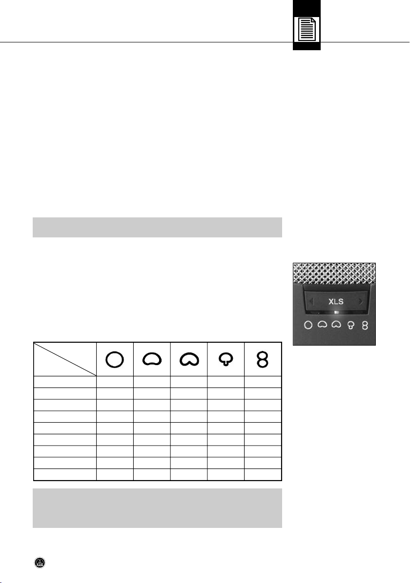
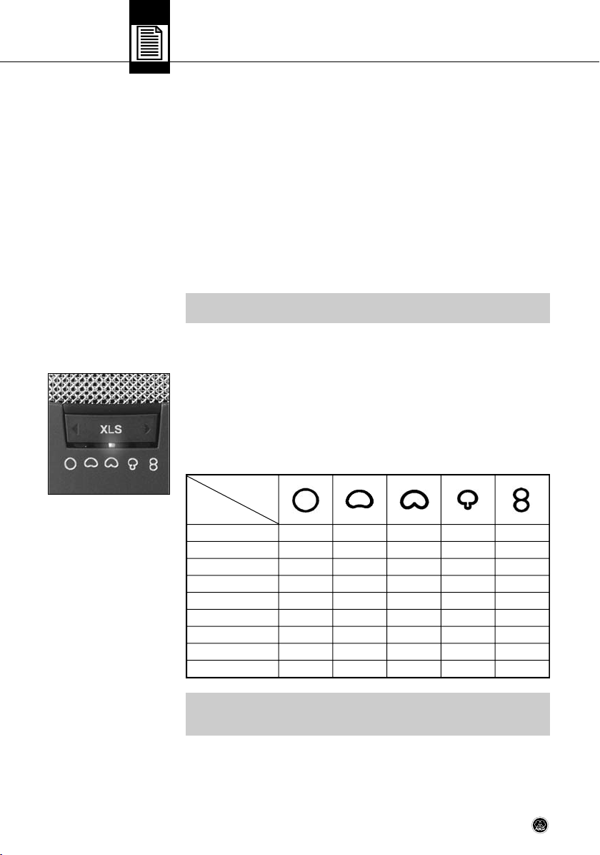
1 Wahlschalter für Richtcharakteristiken*)
Der Wahlschalter 1 an der Vorderseite des Mikrofons (siehe Abb. 1) erlaubt die Auswahl von
neun fein abgestuften Richtcharakteristiken entsprechend den legendären AKG Studiomikrofonen C 12 und C 12 VR. Damit steht für jede Aufnahmesituation die optimale Richtcharakteristik für bestmögliche Ergebnisse zur Verfügung. Alle Richtcharakteristiken sind
weitgehend frequenzunabhängig. Es wird somit auch der Klangcharakter des indirekten
Schalls naturgetreu und unverfälscht wiedergegeben.
Die LEDs unterhalb des Wahlschalters zeigen die gewählte Richtcharakteristik wie folgt an:
Richtcharakteristik
Kugel
Zwischenstellung
Breite Niere
Zwischenstellung
Niere
Zwischenstellung
Hyperniere
Zwischenstellung
Acht
• Ca. 500 ms nach dem Verändern der Richtcharakteristik, Vorabschwächung oder Tiefenabsenkung wird die aktuelle Einstellung des Mikrofons automatisch gespeichert.
Nach dem Abschalten und erneuten Einschalten der Versorgungsspannung (Phantomspeisung) wird diese Einstellung automatisch wiederhergestellt.
LED
Hinweis:
Lock Mode abschalten:
Abb. 1: Wahlschalter für
Richtcharakteristiken
Tabelle 1: Anzeige der gewählten Richtcharakteristik
Hinweis:
5C 414 XLS / XLII
Page 6
2 Beschreibung
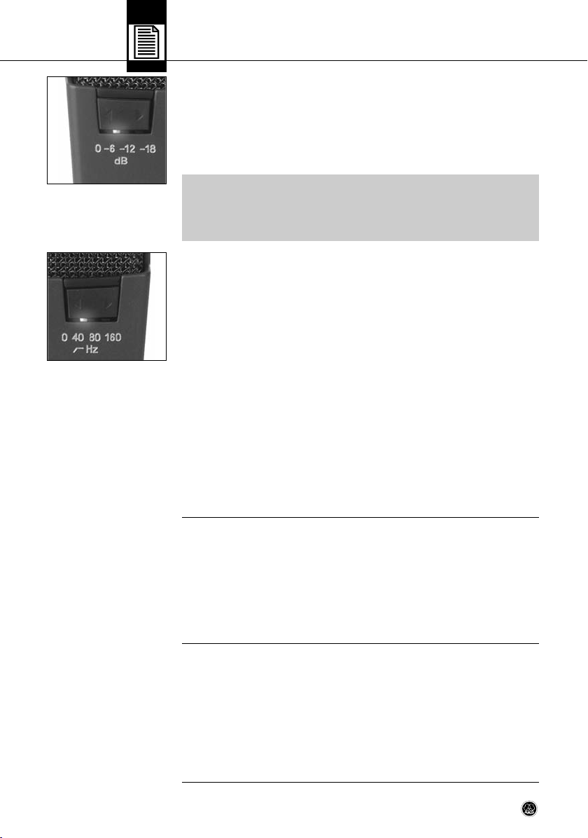
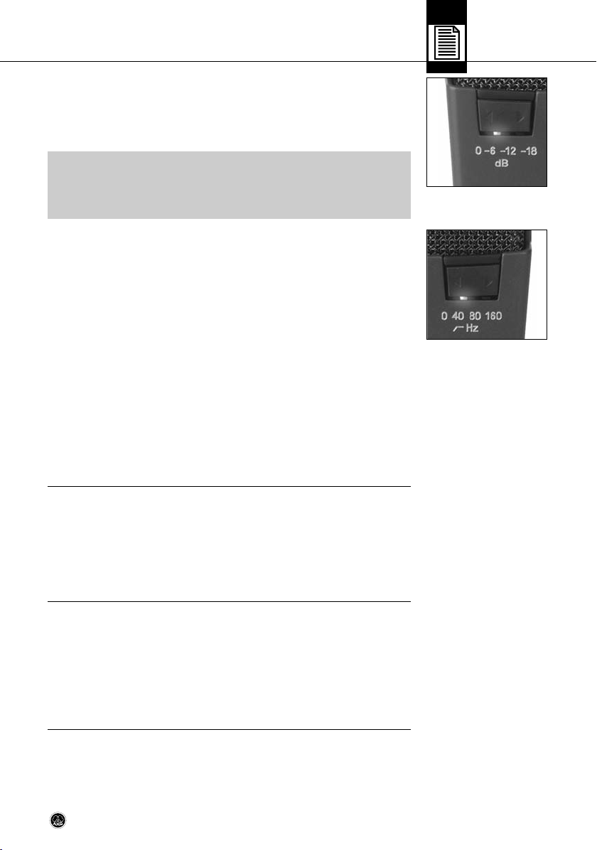
2 Wahlschalter für Vorabschwächung*)
Der Wahlschalter 2 an der Rückseite des Mikrofons (siehe Abb. 2) erlaubt, die Aussteuerungsgrenze um 6 dB, 12 dB oder 18 dB hinaufzusetzen, um auch im Nahbereich von Schallquellen verzerrungsfreie Aufnahmen machen zu können. Diese Vorabschwächung verhindert,
dass der Ausgangspegel des Mikrofons besonders bei tiefen Frequenzen kritische Aussteuerungsgrenzen von Kleinsttransformatoren, die z.B. in Mischpulteingängen verwendet
werden, überschreitet.
Abb. 2: Wahlschalter
für Vorabschwächung
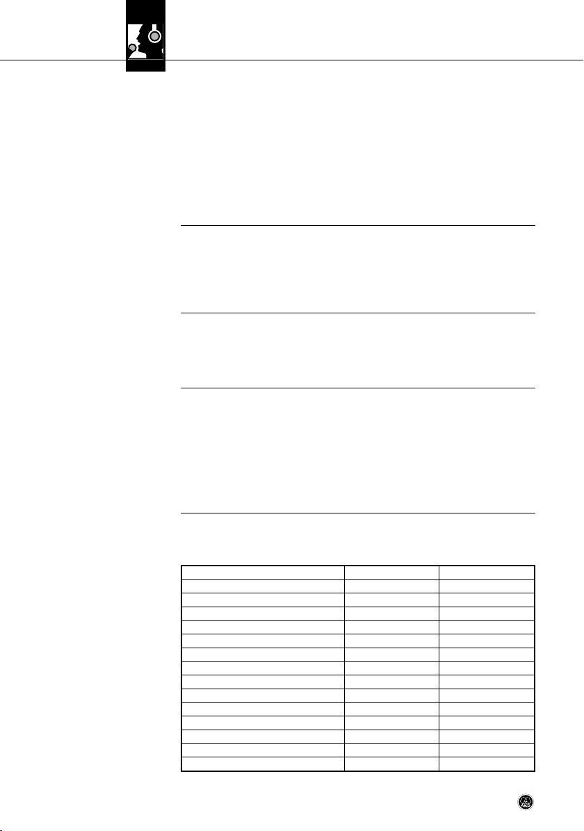
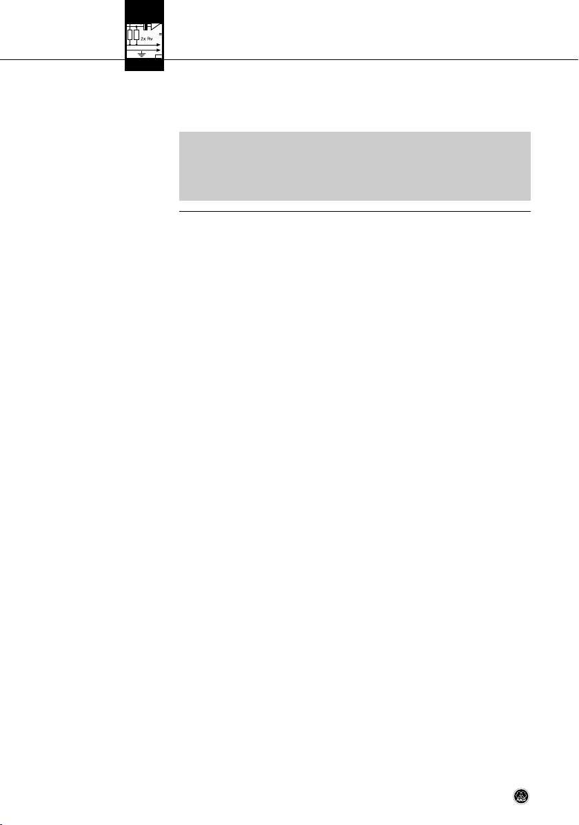
Abb. 3: Wahlschalter
für Tiefenabsenkung
2.4 C 414 XLII
*) Hinweis:
• Um die Rauschwerte der Eingangsstufe im Mikrofon möglichst gering zu halten, wurde
der gesamte Kapselbereich schaltungstechnisch extrem hochohmig gestaltet. Deshalb dauert es etwa 10 bis 15 Sekunden, bis die Richtcharakteristik- oder Vorabschwächungseinstellung vollständig wirksam wird.
3 Wahlschalter für Tiefenabsenkung
Die schaltbare Tiefenabsenkung (siehe Abb. 3) hilft zusätzlich, Verzerrungen bei tiefsten Frequenzen zu reduzieren, die z.B. durch Rumpel- oder Windgeräusche auftreten können. Die
Steilheit des Filters beträgt mehr als 12 dB/Oktave bei den Eckfrequenzen 40 Hz und 80 Hz
sowie 6 dB/Oktave bei der Eckfrequenz 160 Hz. Die Einstellung 160 Hz reduziert sehr wirksam den Nahbesprechungseffekt, der bei geringen Mikrofonabständen (weniger als 15 cm)
zur Schallquelle auftreten kann.
Übersteuerungsanzeige mit Peak Hold (Spitzenwert-Halte-) Funktion
Die LEDs zur Anzeige der Richtcharakteristik dienen auch als Übersteuerungsanzeige.
Bei herkömmlichen Spitzenwertanzeigen können Übersteuerungen, die nur den Bruchteil
einer Sekunde lang dauern, leicht übersehen werden. Die neue Peak Hold Funktion des
C 414 XLS und C 414 XLII macht jedoch auch extrem kurz andauernde Übersteuerungen
sichtbar: Wenn der Ausgangspegel des Mikrofons einen Wert von ca. 2 dB unter der zulässigen Aussteuerungsgrenze erreicht oder überschreitet, wechselt die aktive Richtcharakteristik-LED ca. 3 Sekunden lang auf rot. Tritt dieser Fall ein, empfehlen wir, die Vorabschwächung mit dem Wahlschalter 2 um eine oder mehrere Stufen zu erhöhen.
Das C 414 XLII wurde als akustische Alternative zur Standard-Version C 414 XLS entwickelt
und kommt klanglich dem legendären AKG C 12 sehr nahe. Es ist mit dem C 414 XLS identisch, weist jedoch durch ein völlig anderes akustisches Reibungselement eine leichte Betonung der hohen Frequenzen ab etwa 3 kHz auf. Diese Höhenanhebung unterstützt die
Präsenz von Gesangsstimmen, wir empfehlen das C 414 XLII daher besonders für die Abnahme von Solostimmen oder Soloinstrumenten (siehe auch Kapitel 4.5 und 4.6). Darüber
hinaus eignet es sich auch hervorragend für Aufnahmen aus größerer Entfernung, z.B. im
Konzertsaal von der Decke abgehängt.
2.5 Stereo Sets
6 C 414 XLS / XLII
Naturgetreue Stereoaufnahmen erfordern hochwertige Mikrofone mit hervorragenden Übertragungseigenschaften. Für ein Stereopaar kommen daher nur Mikrofone mit möglichst identischen Übertragungseigenschaften und hoher räumlicher Abbildungstreue über den
kompletten Frequenzbereich in Frage.
Jedes C 414 Stereopaar wird daher im Werk aus Tausenden Einzelmikrofonen nach der von
AKG eigens entwickelten computergestützten Methode sorgfältig ausgewählt.
Die C 414 XLS und C 414 XLII Stereo Sets bieten somit höchstmögliche Korrelation über den
gesamten Übertragungsbereich und praktisch identische Empfindlichkeit der beiden Mikrofone für beeindruckend räumliche Stereoaufnahmen.
Page 7

3 Stromversorgung
C 414 XLS und C 414 XLII zeichnen sich durch extrem niedriges Eigenrauschen und gleichzeitig hohe Übersteuerungsfestigkeit aus. Um diese strengen technischen Anforderungen zu
erfüllen, wurden beide Mikrofone für den ausschließlichen Betrieb mit 48-V-Phantomspeisung nach IEC 61938 ausgelegt. Diese Norm schreibt eine positive Spannung von 48 V
an den NF-Leitungen gegen die Kabelabschirmung vor.
• Verbinden Sie das Mikrofon ausschließlich mit Phantomspeisequellen (Eingang
mit Phantomspeisung oder externes Phantomspeisegerät) nach IEC 61938 mit
erdfreiem Anschluss und verwenden Sie dazu ausschließlich ein symmetrisches Kabel mit Studiosteckverbindern nach IEC 268-12. Nur so kann ein sicherer und problemloser Betrieb garantiert werden.
!
L
Wichtig!
7C 414 XLS / XLII
Page 8
4 Anwendungshinweise
4.1 Einleitung
(C 414 XLII siehe Kapitel 2.4.)
4.2 Tiefenabsenkung
4.3 Vorabschwächung
4.4 Montage am Stativ
Neben der hohen Aussteuerbarkeit bei geringsten Verzerrungen und der temperatur- und
feuchtigkeitssicheren Konstruktion bietet das Mikrofon einmalige universelle Anwendbarkeit.
Die Standardversion C 414 XLS besitzt einen sehr ausgeglichenen Frequenzverlauf, mit
einem für AKG-Großmembran-Mikrofone typischen Klangcharakter. Dieser Klangcharakter
hat sich über die lange Produktionszeit des C 414 nur unwesentlich verändert. Das C 414
entwickelte sich daher zu einem "Indu striestandard", mit dem die meisten Mitbewerbsprodukte oder neue Produktentwicklungen immer wieder verglichen werden.
Das C 414 XLS können Sie für die meisten Musikinstrumente einsetzen (siehe auch Kapitel
4.5 und 4.6). Mit dem Schalter 1 können Sie die Richtcharakteristik des Mikrofons optimal
an das jeweilige Instrument und die Aufnahmesituation anpassen.
Die schaltbare Tiefenabsenkung im Frequenzbereich von 40 bis 160 Hz erlaubt Ihnen, "akustische Störquellen" wie z.B. Luftströmungen von Klimaanlagen o.ä. oder tieffrequente Vibrationen infolge von Bodenschwingungen, Hantierungs geräuschen usw. wirksam
auszublenden, ohne den Klang charakter des/der aufzunehmenden Instruments/Stimme zu
verändern.
Mit der schaltbaren Vorabschwächung können Sie die akustische Aussteuerbarkeit des Mikrofons erhöhen. Achten Sie jedoch darauf, dass der maximale Pegel am Ausgang des Mikrofons von den nachgeschalteten Geräten (Mikrofon vorverstärker, Mischpulteingängen,
Eingängen von Aufnahme geräten) verzerrungsfrei verarbeitet werden kann.
• Die mitgelieferte elastische Aufhängung H 85 besitzt einen Standard-3/8"Gewindeeinsatz. Damit können Sie das Mikrofon auf nahezu allen handelsüblichen Stativen und
Aufhängungen mit 3/8"-Gewinde montieren.
• Zur Montage auf Stativen mit 5/8"-Gewinde entfernen Sie den Gewindeeinsatz und
schrauben Sie die elastische Halterung direkt auf das Stativ.
• Um die elastische Halterung vom Mikrofon abzunehmen, drehen Sie die bajonettähnliche Sicherung am unteren Ende der Halterung gegen den Uhrzeigersinn, um die Sicherung zu öffnen.
4.5 Anwendungsgebiete
Tabelle 2: Empfohlene
Anwendungen
8 C 414 XLS / XLII
Wir empfehlen das C 414 XLS und C 414 XLII für folgende Anwendungen im Aufnahmestudio:
Aufnahmequelle C 414 XLS C 414 XLII
Lead/Solo Vocals • ••
Backing Vocals/Chor ••
Sprache • ••
Akust. Gitarre •• ••
E-Gitarre •
E-Bass •
Kontrabass ••
Violine •• •
Cello •• •
Zither • ••
Flügel (klassisch) ••
Klavier (Rock&Jazz) •• ••
Orgel •• •
Trompete •• ••
Page 9
4 Anwendungshinweise
Aufnahmequelle C 414 XLS C 414 XLII
Posaune •• •
Horn •• ••
Tuba •• •
Saxophon •• ••
Querflöte •• ••
Klarinette •• ••
Mundharmonika • ••
Bass Drum ••
Tom s • •
Becken •
Bongos, Congas •
• Empfohlen
•• Besonders empfohlen
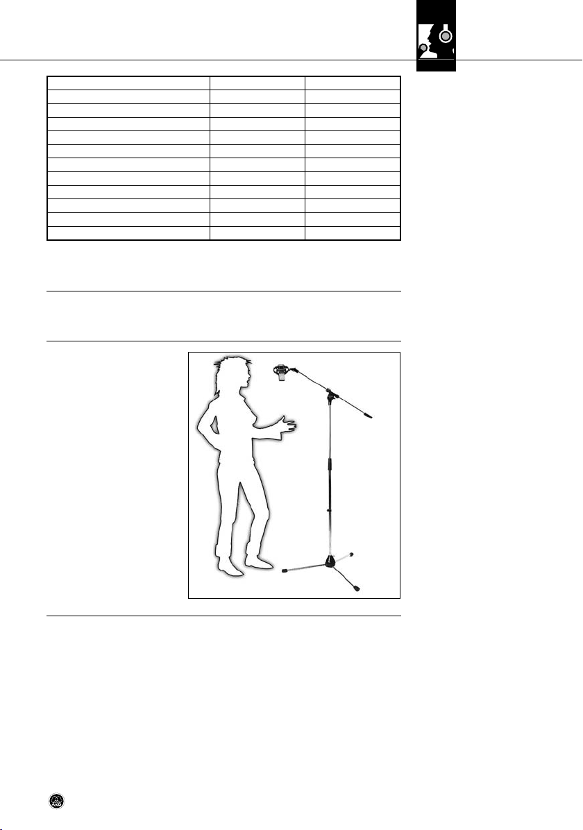
Als Einstieg in die "Wissenschaft der Aufnahmetechnik" finden Sie im folgenden einige bewährte Mikrofonaufstellungen.
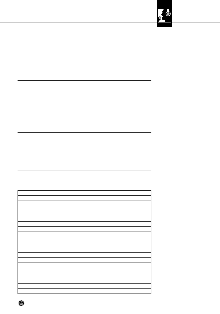
• Mikrofonabstand: 15 - 30 cm
• Richtcharakteristik: Niere
• Tiefenabsenkung: ein (40 oder
80 Hz)
• Windschutz W 414X oder Popschutz PF 80 empfohlen
• Wir empfehlen, während der
Aufnahme dem Sänger/Sprecher zur besseren Kon trolle der
eigenen Stimme seine eigene
Spur im Kopfhörer zu zumischen.
(Tabelle 2)
4.6 Aufstellungstipps
4.6.1 Solostimme
Abb. 4: Solosängerin
9C 414 XLS / XLII
Page 10
4 Anwendungshinweise
4.6.2 Chor/Begleitchor
Abb. 5: Begleitchor
mit einem Mikrofon
(Variante 3)
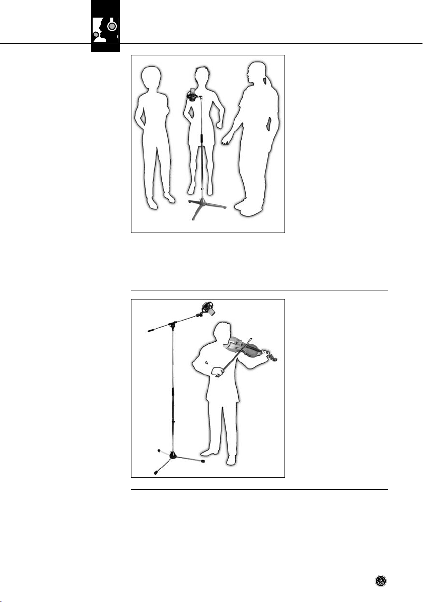
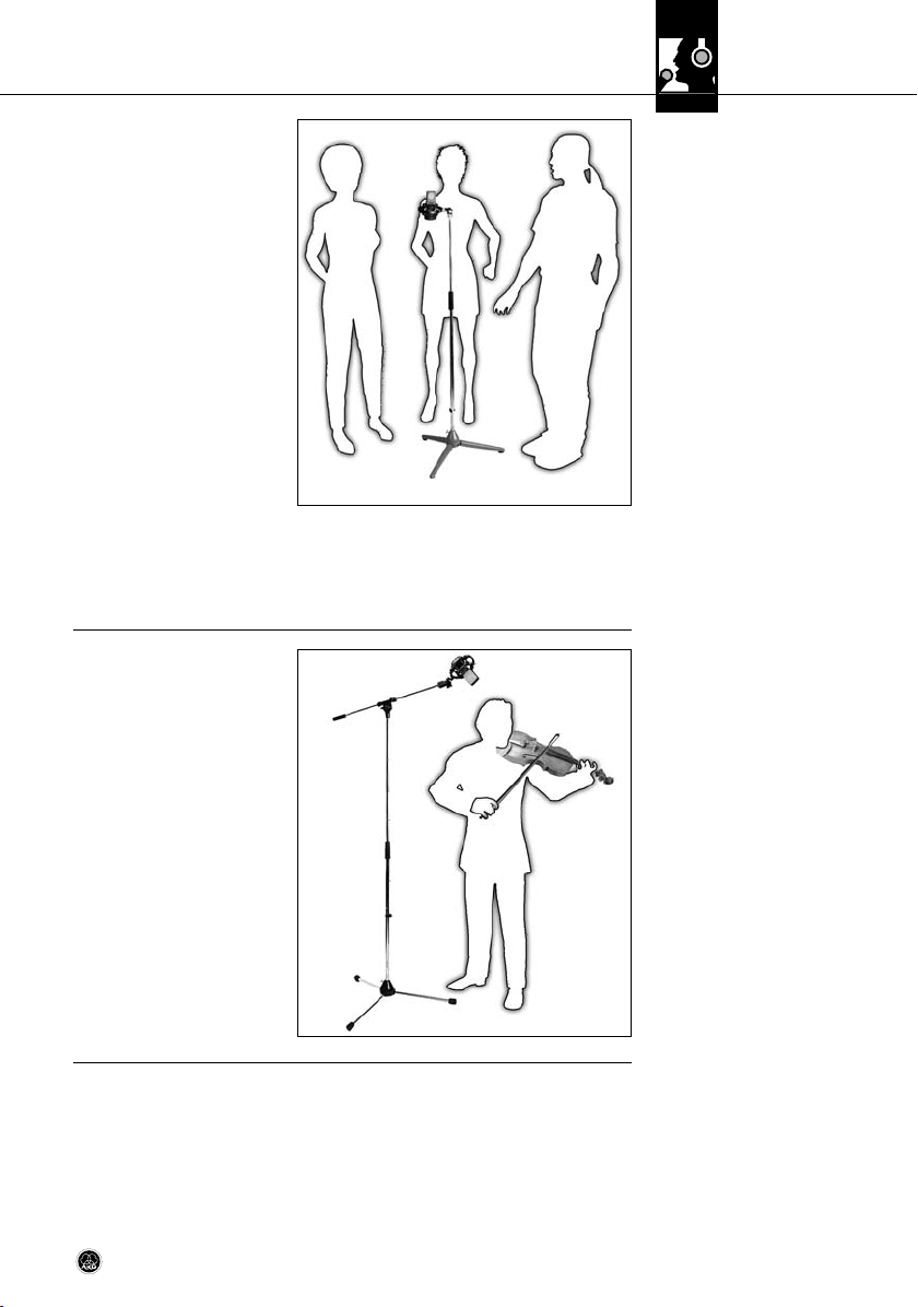
4.6.3 Violine, Viola
Für große gemischte Chöre empfehlen wir ein Stereo mikrofon sowie
je ein Stützmikrofon für Sopran, Alt,
Tenor und Bass.
In akustisch optimalen Räumen genügt oft ein einziges Stereomikrofon
bzw. zwei abgestimmte Monomikrofone.
Begleitchor/Variante 1: Falls genügend Spuren vorhanden sind,
empfehlen wir, jede Stimme einzeln
nacheinander aufzunehmen. Siehe
Kapitel 4.6.1 Solostimme.
Begleitchor/Variante 2:
Bei gleichzeitiger Auf nahme mehrerer Stim men mit je einem Mikro fon
pro Stimme wählen Sie, besonders
bei enger Mikrofon aufstellung, als
Richt charakteristik Hyper niere, um Übersprechen zu vermeiden.
Begleitchor/Variante 3:
Bei Einsatz eines einzigen Mikrofons wählen Sie als Richtcharak teristik Niere oder Kugel und
platzieren Sie den Chor in einem Halbkreis vor dem Mikrofon.
Solovioline:
Richten Sie das Mikro fon aus einer
Höhe von 1,8 bis 2,5 m auf die FLöcher aus.
Große Streichergrup pen:
Verwenden Sie ein Stereo Haupt mikrofon in XY-, MS-, ORTF- oder
anderer Anordnung, kombiniert mit
Stütz mikro fo nen im Nah bereich.
Viola:
Richten Sie das Mikro fon aus einer
Höhe von 2,2 bis 3 m auf die F-Löcher aus.
Abb. 6: Violine
10 C 414 XLS / XLII
Page 11
4 Anwendungshinweise
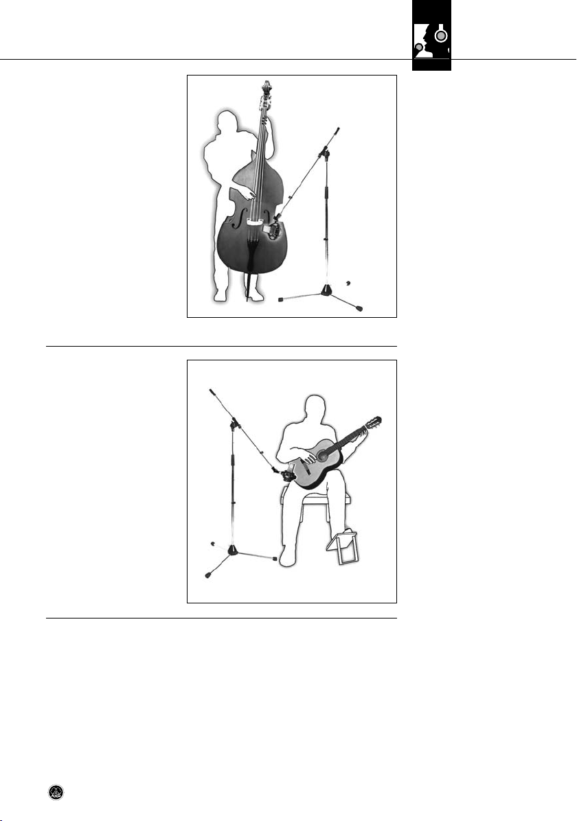
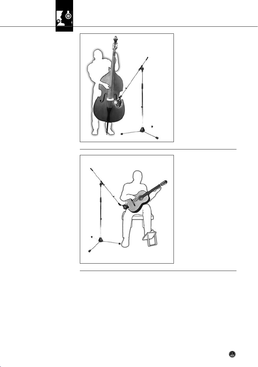
Kontrabass:
Richten Sie das Mikro fon aus einer
Entfernung von ca. 40 cm auf eines
der F-Löcher. Falls der Kontrabass
gleich zeitig mit einem Ensemble
aufgenommen werden muss, den
Abstand verringern und die Richt charakteristik Hyper niere einsetzen,
um Übersprechen anderer Instru mente in das Bass Mikrofon zu vermeiden.
Cello/Variante 1:
Siehe Kontrabass.
Cello/Variante 2:
Nahbereichsmikrofon wie Variante 1
plus Raummikrofon. Pegel des Nahbereichsmikrofons ca. 20 dB unter
den Pegel des Raummikrofons einstellen.
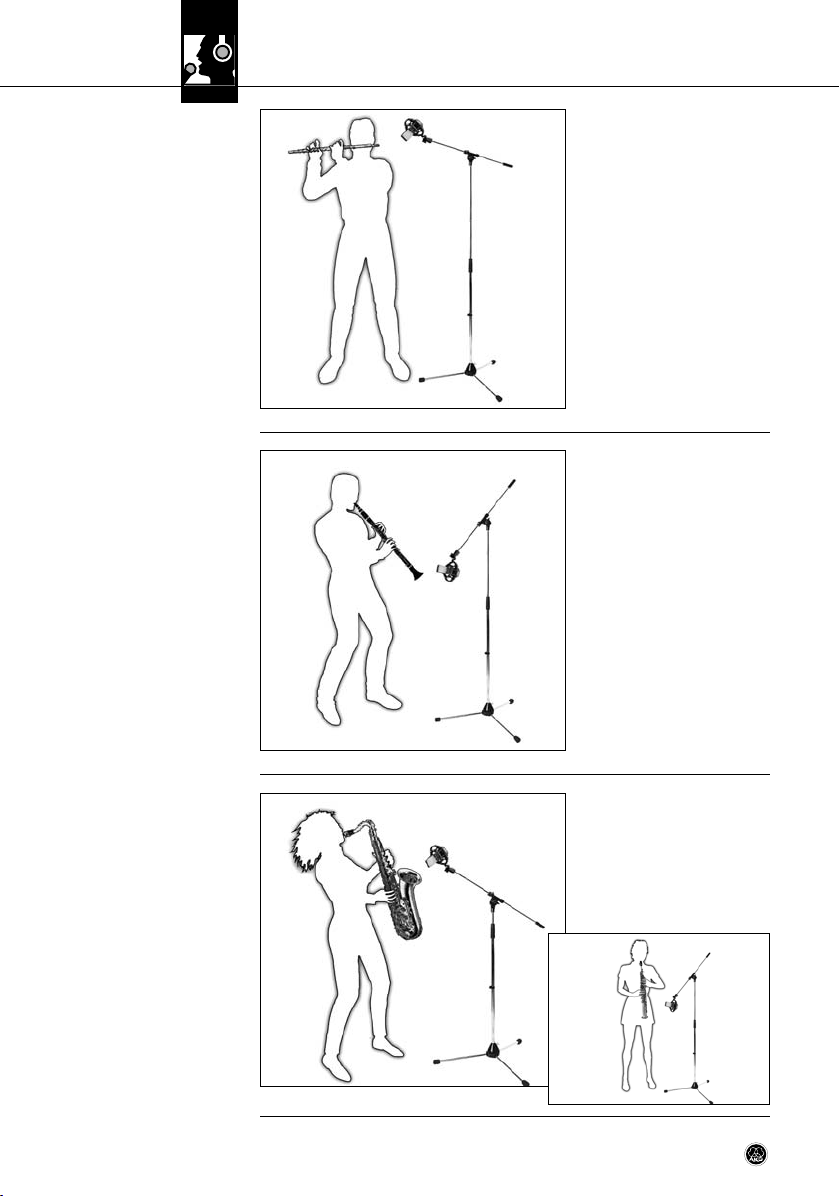
Wir empfehlen, zwei Mi krofone zu
verwenden.
Richten Sie ein C 414 aus einer Entfernung von 20 bis 30 cm auf das
Schallloch aus. Richten Sie ein
Kleinmembran mikrofon (z.B. C 451B)
aus ca. 1 m Entfernung auf einen
Punkt in der Nähe des Stegs oder
von hinten/unten auf den Korpus.
4.6.4 Kontrabass, Cello
Abb. 7: Kontrabass
4.6.5 Akustische Gitarre
Abb. 8: Akustische Gitarre
mit einem C 414
11C 414 XLS / XLII
Page 12
4 Anwendungshinweise
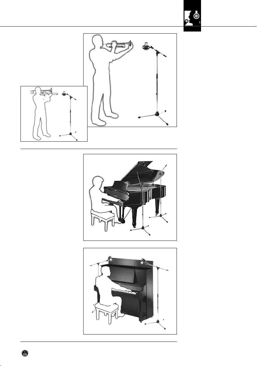
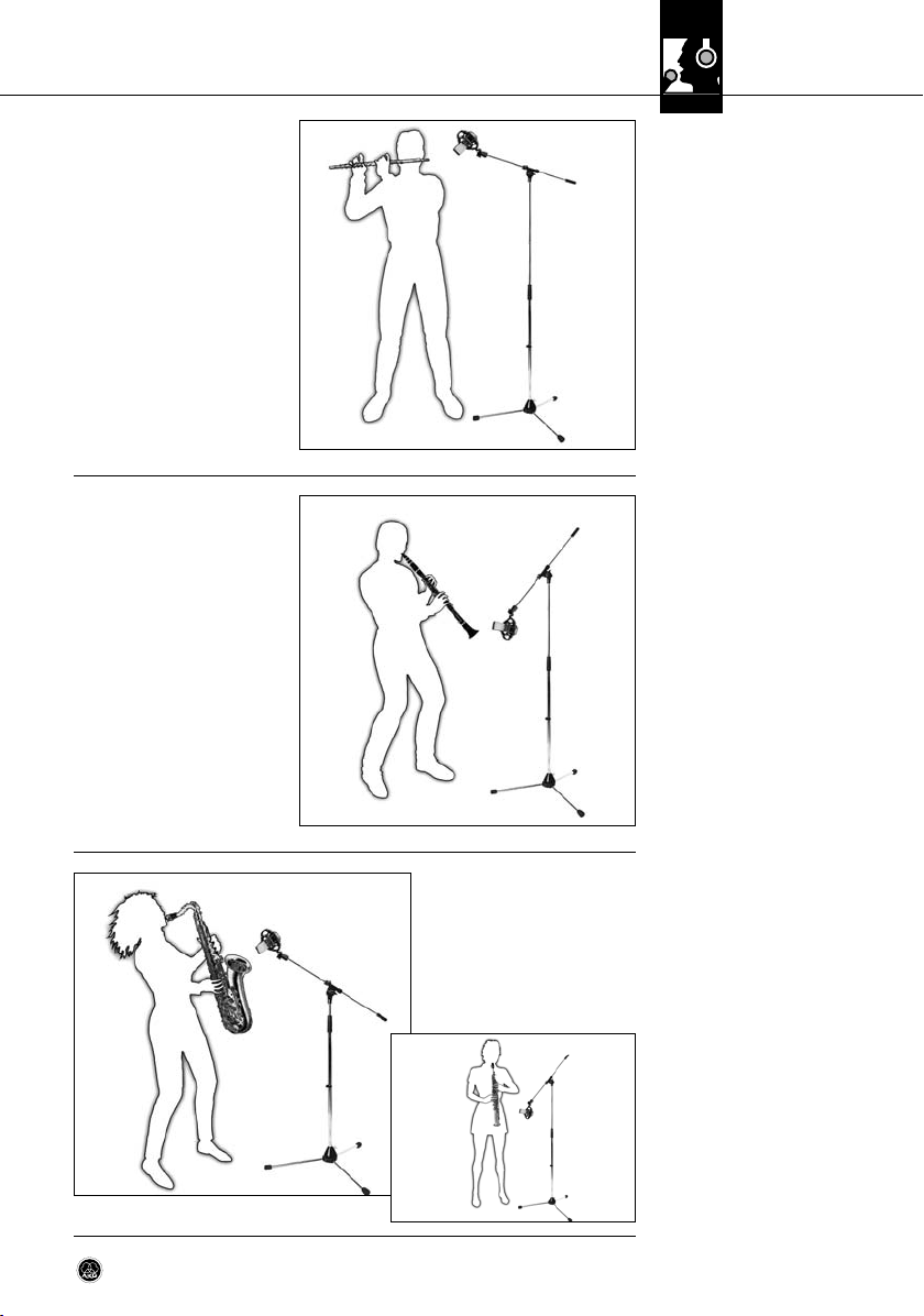
4.6.6 Querflöte
Abb. 9: Abnahme der Quer-
flöte mit nur einem Mikrofon
4.6.7 Klarinette
Wir empfehlen, zwei Mi krofone zu
verwenden.
Richten Sie Mikrofon 1 schräg von
oben auf den Mund des Spielers
(wenig Anblasgeräu sche), Mikro 2
seitlich auf das Instrument.
Abnahme mit nur einem Mikrofon:
Wie Mikrofon 1, in ca. 2 m Abstand,
2 bis 2,5 m über dem Fuß boden.
Richten Sie das Mikro fon auf die
letzte untere Klappe. Um Klappen geräusche zu minimieren, stellen
Sie das Mi krofon etwas seitlich vom
Instrument auf.
Abb. 10: Klarinette
4.6.8 Tenor/
Sopransaxophon
Abb. 11: Tenorsaxophon (a),
Sopransaxophon (b)
12 C 414 XLS / XLII
a
Richten Sie das Mikro fon aus einer
Entfernung von ca. 50 cm bis 1 m
auf die Mitte des Instru ments aus.
b
Page 13
4 Anwendungshinweise
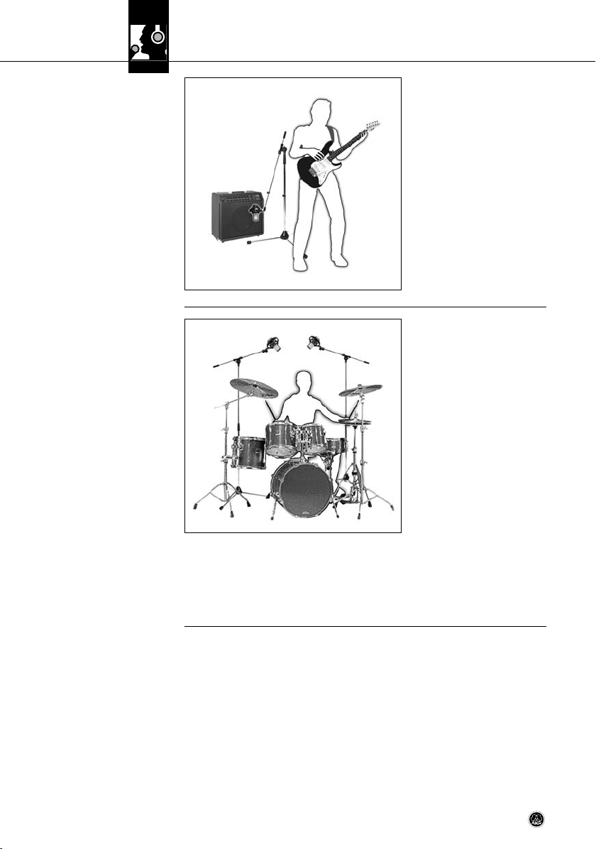
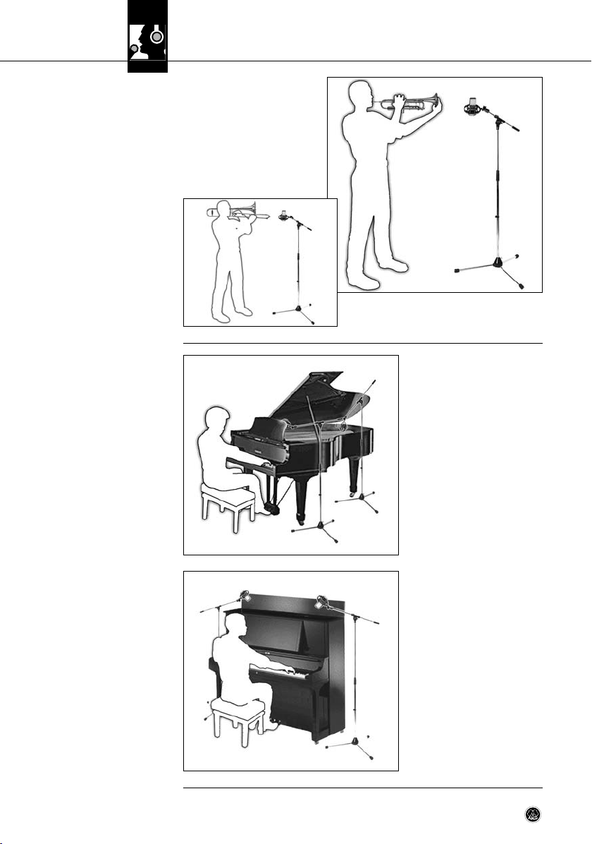
Stellen Sie das Mikrofon ca. 30 cm
vor dem In strument, etwas außerhalb der Achse des Schallbechers,
auf. Schal ten Sie am Mikro fon die
Vorabschwäch ung ein. Der mitgelieferte Windschutz hilft, Blasgeräusche zu reduzieren.
b
Flügel:
Richten Sie ein C 414 oder zwei
C 414 in XY-, MS- oder ORTF-Anord nung aus einer Höhe von 1,5 bis
2 m auf die mittleren Saiten.
Für Rock/Pop-Sounds ver wenden
Sie zwei C 414, ca. 20-40 cm über
den Saiten. Richten Sie Mikro 1 auf
den Diskant bereich, Mikro 2 auf den
Bassbereich jeweils ca. 15 cm hinter den Dämpfern.
4.6.9 Trompete/Posaune
a
Abb. 12: Trompete (a),
Posaune (b)
4.6.10 Flügel/Pianino
Pianino:
Abnahme wie Flügel. Öffnen Sie den
Deckel und lassen Sie die Mikrofone
von oben "in das Instru ment
schauen".
Abb. 13: Flügel
Abb. 14: Pianino
13C 414 XLS / XLII
Page 14
4 Anwendungshinweise
4.6.11 E-Gitarre/E-Bass
Abb. 15: E-Gitarre
4.6.12 Schlagzeug
Abb. 16: Schlagzeug
E-Gitarre:
Stellen Sie das Mikrofon in einem
Abstand von 8-15 cm leicht außerhalb der Mitte der Laut sprechermembran auf. Aktivieren Sie Tiefenab senkung und Vorab schwächung.
Eventuell ein zweites Raum mikro fon
einsetzen.
E-Bass:
Wie E-Gitarre. Sie können zusätzlich
das direkte Signal vom Line-Ausgang des Bassverstärkers über eine
DI-Box zum Mikrofon signal mischen.
Overhead-Abnahme:
Positionieren Sie zwei C 414 in ABoder XY- Technik 80 cm bis 120 cm
über dem Kopf des Schlagzeugers.
Die se Technik liefert ein sehr natürliches Klang bild des gesamten
Schlagzeugs (wenig oder gar keine
Entzerrung/Klangregelung einsetzen!).
Hänge-Toms und Floor-Toms:
Richten Sie aus einer Entfernung
von 5 bis
10 cm ein Mikrofon pro Tom oder je
ein Mikrofon zwischen zwei Toms
auf den Rand des Schlagfells aus.
Um Übersprechen von anderen In-
strumenten zu reduzieren, senken Sie am Mischpult die Höhen über 10 kHz ab.
Bassdrum:
Entfernen Sie das Resonanzfell und positionieren Sie das Mikrofon direkt im Kessel. Aktivieren
Sie unbedingt die Vorabschwächung (-18 dB), da Schallpegel von bis zu 160 dB SPL auftreten können.
14 C 414 XLS / XLII
Page 15

5 Reinigung
• Reinigen Sie die Gehäuseoberfläche des Mikrofons mit einem mit Wasser befeuchteten
Tuc h.
• Waschen Sie den Schaumstoff-Windschutz mit Seifenwasser. Der Windschutz ist sofort
nach dem Trocknen wieder einsatzbereit.
5.1 Mikrofon
5.2 Windschutz
6 Technische Daten
Arbeitsweise: 25 mm-Großmembransystem nach Druckgradientenprinzip
Anzahl der Richtcharakteristiken: 9, umschaltbar
Leerlauf-Übertragungsfaktor: 23 mV/Pa (-33 dBV ± 0,5 dB)
Übertragungsbereich: 20 bis 20.000 Hz (siehe
Elektrische Impedanz: ≤ 200 Ohm
Empfohlene Lastimpedanz: ≥ 2200 Ohm
Steilheit des Tiefenabsenkungs-Filters: 12 dB/Oktave mit Einsatzpunkt bei 40 Hz und 80 Hz, oder
Vorabschwächung: schaltbar auf -6 dB, -12 dB, -18 dB
Ersatzgeräuschpegel nach IEC 60268-4: 20 dB (0 dB Vorabschwächung)
Äquivalentschalldruckpegel nach IEC 60268-4 (A-bew.): 6 dB-A (0 dB Vorabschwächung)
Geräuschpegelabstand bez. auf 1 Pa (A-bew.): 88 dB
Grenzschalldruck für k = 0,5%: 200/400/800/1600 Pa Ⳏ 140/146/152/158 dB SPL
Dynamikbereich: 134 dB min.
Max. Ausgangspegel: 5 V eff. (+14 dBV)
Zulässige klimatische Verhältnisse: Temperaturbereich: -10°C bis +60°C
Speisespannung: 48 Volt Phantomspeisung nach IEC 61938
Stromaufnahme: ca. 4,5 mA
Steckerbeschaltung: XLR-3 Type nach IEC
Äussere Abmessungen: 50 x 38 x 160 mm
Gewicht: 300 g, netto
Patente: Elektrostatischer Wandler (Patentnr. AT 395.225, DE 4.103.784,
Frequenzkurven)
6 dB/Oktave mit Einsatzpunkt bei 160 Hz
(0/-6/-12/-18 dB)
Rel. Luftfeuchte: 95% (+20°C), 85% (+60°C)
JP 2.815.488, US 7,356,151)
Dieses Produkt entspricht den in der Konformitätserklärung angegebenen Normen. Sie können die Konformitätserklärung
auf http://www.akg.com oder per E-Mail an sales@akg.com anfordern.
15C 414 XLS / XLII
Page 16
6 Technische Daten
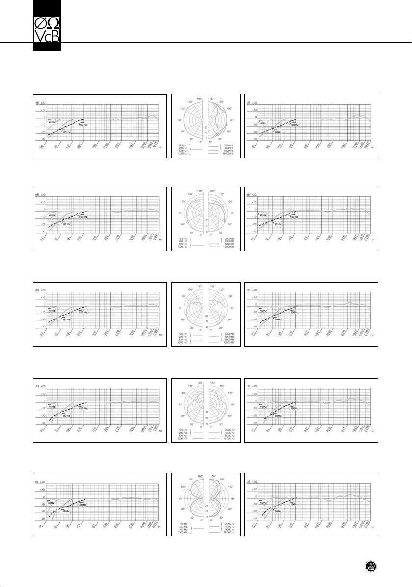
Frequenzgang
C 414 XLS
Polardiagramm
C 414 XLS / C 414 XLII
Kugel
Breite Niere
Niere
Frequenzgang
C 414 XLII
Hyperniere
Achter
16 C 414 XLS / XLII
Page 17

Table of Contents
Page
Welcome! . . . . . . . . . . . . . . . . . . . . . . . . . . . . . . . . . . . . . . . . . . . . . . . . . . . . . . . . . . . . . . . 18
1 Safety and Environment . . . . . . . . . . . . . . . . . . . . . . . . . . . . . . . . . . . . . . . . . . . . . . . . . . 18
1.1 Safety. . . . . . . . . . . . . . . . . . . . . . . . . . . . . . . . . . . . . . . . . . . . . . . . . . . . . . . . . . . . . 18
1.2 Environment . . . . . . . . . . . . . . . . . . . . . . . . . . . . . . . . . . . . . . . . . . . . . . . . . . . . . . . . 18
2 Description . . . . . . . . . . . . . . . . . . . . . . . . . . . . . . . . . . . . . . . . . . . . . . . . . . . . . . . . . . . . 19
2.1 Packing List. . . . . . . . . . . . . . . . . . . . . . . . . . . . . . . . . . . . . . . . . . . . . . . . . . . . . . . . . 19
2.2 Optional Accessories . . . . . . . . . . . . . . . . . . . . . . . . . . . . . . . . . . . . . . . . . . . . . . . . . . 19
2.3 C 414 XLS. . . . . . . . . . . . . . . . . . . . . . . . . . . . . . . . . . . . . . . . . . . . . . . . . . . . . . . . . . 19
2.3.1 Controls . . . . . . . . . . . . . . . . . . . . . . . . . . . . . . . . . . . . . . . . . . . . . . . . . . . . . . . 19
2.4 C 414 XLII . . . . . . . . . . . . . . . . . . . . . . . . . . . . . . . . . . . . . . . . . . . . . . . . . . . . . . . . . . 21
2.5 Stereo Pairs. . . . . . . . . . . . . . . . . . . . . . . . . . . . . . . . . . . . . . . . . . . . . . . . . . . . . . . . . 21
3 Powering. . . . . . . . . . . . . . . . . . . . . . . . . . . . . . . . . . . . . . . . . . . . . . . . . . . . . . . . . . . . . . 22
4 Using Your Microphone . . . . . . . . . . . . . . . . . . . . . . . . . . . . . . . . . . . . . . . . . . . . . . . . . . . 23
4.1 Introduction. . . . . . . . . . . . . . . . . . . . . . . . . . . . . . . . . . . . . . . . . . . . . . . . . . . . . . . . . 23
4.2 Bass Cut Filters . . . . . . . . . . . . . . . . . . . . . . . . . . . . . . . . . . . . . . . . . . . . . . . . . . . . . . 23
4.3 Preattenuation Pads. . . . . . . . . . . . . . . . . . . . . . . . . . . . . . . . . . . . . . . . . . . . . . . . . . . 23
4.4 Stand Mounting . . . . . . . . . . . . . . . . . . . . . . . . . . . . . . . . . . . . . . . . . . . . . . . . . . . . . . 23
4.5 Application Areas. . . . . . . . . . . . . . . . . . . . . . . . . . . . . . . . . . . . . . . . . . . . . . . . . . . . . 23
4.6 Hints on Micorphone Placement . . . . . . . . . . . . . . . . . . . . . . . . . . . . . . . . . . . . . . . . . . 24
4.6.1 Lead Vocals . . . . . . . . . . . . . . . . . . . . . . . . . . . . . . . . . . . . . . . . . . . . . . . . . . . . 24
4.6.2 Choir, Backing Vocals. . . . . . . . . . . . . . . . . . . . . . . . . . . . . . . . . . . . . . . . . . . . . . 25
4.6.3 Violin, Viola . . . . . . . . . . . . . . . . . . . . . . . . . . . . . . . . . . . . . . . . . . . . . . . . . . . . . 25
4.6.4 Double Bass, Cello. . . . . . . . . . . . . . . . . . . . . . . . . . . . . . . . . . . . . . . . . . . . . . . . 26
4.6.5 Acoustic Guitar . . . . . . . . . . . . . . . . . . . . . . . . . . . . . . . . . . . . . . . . . . . . . . . . . . 26
4.6.6 Flute . . . . . . . . . . . . . . . . . . . . . . . . . . . . . . . . . . . . . . . . . . . . . . . . . . . . . . . . . 27
4.6.7 Calrinte . . . . . . . . . . . . . . . . . . . . . . . . . . . . . . . . . . . . . . . . . . . . . . . . . . . . . . . 27
4.6.8 Tenor and Soprano Saxophones . . . . . . . . . . . . . . . . . . . . . . . . . . . . . . . . . . . . . . 27
4.6.9 Trumpet, Trombone . . . . . . . . . . . . . . . . . . . . . . . . . . . . . . . . . . . . . . . . . . . . . . . 28
4.6.10 Grand and Upright Pianos . . . . . . . . . . . . . . . . . . . . . . . . . . . . . . . . . . . . . . . . . 28
4.6.11 Electric Guitar and Bass . . . . . . . . . . . . . . . . . . . . . . . . . . . . . . . . . . . . . . . . . . . 29
4.6.12 Drums . . . . . . . . . . . . . . . . . . . . . . . . . . . . . . . . . . . . . . . . . . . . . . . . . . . . . . . 29
5 Cleaning . . . . . . . . . . . . . . . . . . . . . . . . . . . . . . . . . . . . . . . . . . . . . . . . . . . . . . . . . . . . . . 30
5.1 Microphone. . . . . . . . . . . . . . . . . . . . . . . . . . . . . . . . . . . . . . . . . . . . . . . . . . . . . . . . . 30
5.2 Windscreen. . . . . . . . . . . . . . . . . . . . . . . . . . . . . . . . . . . . . . . . . . . . . . . . . . . . . . . . . 30
6 Specifications . . . . . . . . . . . . . . . . . . . . . . . . . . . . . . . . . . . . . . . . . . . . . . . . . . . . . . . . . . 30
17C 414 XLS / XLII
Page 18
L
Welcome!
Thank you for purchasing an AKG product. This Manual contains important instructions for
setting up and operating your equipment. Please take a few minutes to read the instructi-
ons below, specifically section 1 Safety and Environment, carefully before operating
the equipment. Please keep the Manual for future reference. Have fun and impress your
audience!
1 Safety and Environment
1.1 Safety
1.2 Environment
• Please make sure that the piece of equipment your microphone will be connected to fulfills the safety regulations in force in your country and is fitted with
a ground lead.
• When scrapping the equipment, separate the case, circuit boards, and cables,
and dispose of all components in accordance with local waste disposal rules.
• The packaging of the equipment is recyclabe. To dispose of the packaging, make
sure to use a collection/recycling system provided for that purpose and observe local legislation relating to waste disposal and recycling.
18 C 414 XLS / XLII
Page 19
2 Description
• C 414 XLS or C 414 XLII
• SA 60 stand adapter
• H 85 shock mount
• PF 80 pop screen
• W 414X foam windscreen
• Original frequency response trace with serial number and production date code
• High quality carrying case
• 2 x C 414 XLS or C 414 XLII
• 2 x SA 60 stand adapter
• 2 x H 85 shock mounts
• 2 x W 414X foam windscreens
• 1 x H 50 stereo bar
• Original frequency response trace with serial number and production date code
• High quality carrying case
• Check that the packaging contains all of the components listed for your model. Should
anything be missing, please contact your AKG dealer.
• For optional accessories, refer to the current AKG catalog or folder, or visit
www.akg.com. Your dealer will be glad to help.
This large-diaphragm condenser microphone has been designed on the basis of feedback
from sound engineers who have used the C 12, C 12A, C 12B, C 414comb, C 414EB-P 48,
C 414B-ULS, C 414B-TL II, and C 414B-XLII microphones in recording studios and on stages
around the world for years. Using advanced, reliable components that provide more functions
in the same space, the C 414 XLS meets the highest professional standards and will withstand the tough handling typically encountered in the recording studio and on stage for many
years.
The electronic circuitry of the microphone has been redesigned to achieve completely linear transfer characteristics of all electrical parameters. Extremely low self-noise and high
headroom add up to a dynamic range of approximately 134 dB (A-weighted) that is far superior to figures quoted for conventional condenser microphones and other studio equipment.
A dual-diaphragm transducer allows you to select one of several polar patterns. The diaphragm is made of a plastic foil that is gold-sputtered on one side only to prevent shorting
to the back electrode even at extremely high sound pressure levels.
The all-metal body adds to the rejection of RF interference so you can use the microphone
near transmitter stations, along with wireless microphones or other communications equipment.
2.1 Packing List
Stero Pairs:
2.2 Optional Accessories
2.3 C 414 XLS
Unlike earlier versions of the C 414, the C 414 XLS / C 414 XLII provides three separate bidirectional pushbuttons for selecting the polar pattern, preattenuation pad, and bass cut filter,
each with an LED bar indicating the selected setting. The selectors and indicator LEDs are
only active as long as power (48 V phantom power) to the microphone is on.
• To select the desired value or polar pattern, press the desired arrow on the appropriate
selector once or several times.
A green LED above the appropriate value or symbol is lit to indicate the selected setting.
To select a different setting after having reached the last position available, press the opposite arrow on the selector. (Pressing the same arrow again will not set the parameter
back to its initial position.)
2.3.1 Controls
19C 414 XLS / XLII
Page 20
2 Description
• When you switch phantom power to the microphone off and back on later, the currently
selected settings of all three selectors will be restored automatically as soon as you
switch phantom power back on.
All settings are saved in memory about 500 msecs. after you last pressed any of the
three selectors. Thus, your latest settings will be available again even if phantom power
ahs been interrupted (e.g., if you disconnected the microphone and connected it again
later).
Lock Mode:
Locking the Controls:
Note:
Unlocking the Controls:
Fig. 1: Polar pattern selector.
Table 1: Indication
of selected polar pattern.
• Live-sound engineers as well as engineers for theater, opera, or musical productions
often use the same microphones for the same purposes every night, and may even install some microphones permanently. In Lock Mode, all controls on the microphone are
disabled so the settings you selected for a specific application (polar pattern, preattenuation pad, bass cut filter) cannot be changed unintentionally.
• Press and hold one of the arrows on the polar pattern selector (1) for at least 2 seconds.
All controls are disabled and remain disabled even if phantom power has been interrupted (e.g., if you disconnected the microphone and connected it again later).
• To indicate that the microphone is in Lock Mode, the LED(s) above the currently selected polar pattern will be lit red momentarily when you press any key.
• To unlock the selectors, press and hold the polar pattern selector (1) for at least 2 seconds again.
1 Polar Pattern Selector
Selector 1 on the microphone front panel (refer to fig. 1) lets you select one of nine carefully
designed polar patterns similar to those of the legendary C 12 and C 12 VR studio microphones from AKG, providing the optimum polar pattern for best possible results in the most
diverse miking situations. All polar patterns are largely frequency-independent for realistic
and uncolored off-axis sound.
The LEDs below the selector indicate the selected polar pattern as shown in Table 1 below:
Polar
pattern
Omnidirectional
Intermediate
Wide cardioid
Intermediate
Cardioid
Intermediate
Hypercardioid
Intermediate
Figure eight
LED
Note:
20 C 414 XLS / XLII
• Approximately 500 msecs. after you changed a polar pattern, preattenuation, or bass
cut setting, your settings will be saved automatically. If you switch phantom power off
and back on later, these settings will be restored automatically.
Page 21
2 Description
2 Preattenuation Pad Selector*)
Selector 2 on the microphone rear panel (refer to fig. 2) lets you increase the headroom by
6 dB, 12 dB, or 18 dB for distortion-free close-in recording. The preattenuation pads prevent the microphone's output level, particularly at low frequencies, from overloading the
miniature transformers used in mixer input stages, etc.
*) Note:
• To keep noise levels in the microphone input stage as low as possible, the entire transducer section uses extremely high-impedance circuitry. Therefore, the selected
(changed) polar pattern or preattenuation setting will take about 10 to 15 seconds to
become fully active.
3 Bass Cut Selector
Selector 3 on the microphone rear panel (refer to fig. 3) reduces low-end distortion caused
by footfall or wind noise, etc. The filter slope is more than 12 dB/octave at the 40 Hz and 80
Hz settings and 6 dB/octave at the 160 Hz setting. The 160 Hz setting minimizes the proximity effect that may arise when close-in miking from less than 6 inches.
Overload Indication with Peak Hold Function
The polar pattern indicator LEDs also provide an overload indication.
With conventional peak indicators, overload peaks lasting only for a fraction of a second may
easily escape your attention. The new peak hold function of the C 414 XLS and C 414 XLII,
however, makes sure you will notice even the shortest overload peak: If the output level of
the microphone equals or exceeds a value of approximately 2 dB below the overload limit,
the currently active polar pattern LED will change to red for about 3 seconds. If this happens,
we recommend increasing the preattenuation by one or more "notches" using Selector 2.
Fig. 2: Preattenuation selector.
Fig. 3: Bass cut selector.
The C 414 XLII has been designed as a sonic alternative to the standard C 414 XLS, and
closely approximates the sound of the legendary AKG C 12. It is identical to the C 414 XLS
with the exception of a completely different acoustic resistor that provides a slight high-frequency rise at 3 kHz and above. This HF boost enhances the presence of vocals, so we
specifically recommend the C 414 XLII for miking up solo voices or solo instruments (see also
sections 4.5 and 4.6). In addition, it is an excellent choice for distant miking, e.g. suspended
from a concert hall ceiling.
Realistic stereo recordings require microphones with outstanding performance and excellent
quality. They also require consistent performance and accurate localization throughout the
entire frequency range from the pair of microphones.
Therefore, every factory-matched pair of C 414s is created from thousands of individual microphones selected by AKG's sophisticated computer-aided matching method.
The C 414 XLS and C 414 XLII matched stereo pairs thus provide the highest possible correlation over the microphones' entire frequency range and virtually identical sensitivity for
stunning, three-dimensional recordings.
2.4 C 414 XLII
2.5 Stereo Pairs
21C 414 XLS / XLII
Page 22
3 Powering
The C 414 XLS and C 414 XLII provide extremely low self-noise yet high headroom. The
only way to meet these strict engineering requirements was to limit the powering options for
both microphones to 48 V phantom power to IEC 61938 only. This standard requires a positive voltage of 48 V with reference to the cable shield.
Important!
!
L
• Do not connect the microphone to any power supply other than a phantom
power source (input with phantom power or external phantom power supply)
to IEC 61938 with a floating connector, using a balanced cable with studio grade
connectors to IEC 268-12 only. This is the only way to ensure safe and reliable
operation.
22 C 414 XLS / XLII
Page 23
4 Using Your Microphone
Besides offering high headroom, minimum distortion, as well as temperature and humidity
resistant construction, the microphone is suited for a uniquely wide range of applications.
The standard version C 414 XLS features a very smooth frequency response and the typical sound of AKG large-diaphragm microphones. This sound has hardly changed over the
many years the C 414 has been in production, and the
C 414 has become an "industry standard" against which most competitive or new products
are compared.
You can use the C 414 XLS for most musical instruments (see also sections 4.5 and 4.6).
Selector 1 lets you optimally adjust the microphone's polar pattern to the instrument to be
recorded and the recording environment.
The switchable bass cut filters at 40 Hz, 80 Hz, and 160 Hz will effectively cancel out any
unwanted noise such as blower noise from air conditioning systems, etc., or low-frequency
noise due to floor vibrations, handling noise, etc. without affecting the sound of the recorded
voice or instrument on tape.
The switchable preattenuation pads allow you to increase the microphone's headroom. Remember to check that the equipment connected to the microphone (microphone preamp,
mixer input, recorder input) can handle the maximum output level of the microphone without causing distortion.
• The supplied H 85 shock mount has a standard 3/8" thread insert so you can mount the
microphone on almost every commercial stand or suspension with a 3/8" thread.
• To mount the H 85 on a stand with a 5/8" thread, remove the tread insert and screw the
H 85 directly on the stand.
• To remove the H 85 from the microphone, rotate the bayonet-type lock at the lower end
of the H 85 CCW to the point that the H 85 unlocks.
We recommend the C 414 XLS and C 414 XLII for the following recording studio applications:
4.1 Introduction
(For details on the C 414 XLII
refer to sectin 2.4.)
4.2 Bass Cut Filters
4.3 Preattenuation Pads
4.4 Stand Mounting
4.5 Application Areas
Sound source C 414 XLS C 414 XLII
Lead/solo vocals • ••
Backing vocals/choir ••
Speech • ••
Acoustic guitar •• ••
Electric guitar •
Electric bass •
Double bass ••
Violin •• •
Cello •• •
Zither • ••
Grand piano (classical) ••
Upright piano (rock & jazz) •• ••
Organ •• •
Trumpet •• ••
Trombone •• •
French horn •• ••
Tuba •• •
Saxophone •• ••
Flute •• ••
Table 2: Recommended
applications.
23C 414 XLS / XLII
Page 24

(Table 2)
4 Using Your Microphone
Sound source C 414 XLS C 414 XLII
Clarinet •• ••
Harmonica • ••
Bass drum ••
Tom s • •
Cymbals •
Bongos, congas •
•• Highly recommended
• Recommended
Microphone Placement
4.6 Hints on
4.6.1 Lead Vocals
Fig. 4: Solo vocalist.
As an introduction to the "secret science of making good recordings", the following sections
describe some proven
miking techniques.
• Working distance: 6 to 12 in.
(15 to 30 cm)
• Polar pattern: cardioid
• Bass cut: ON (40 or 80 Hz)
• W 414X windscreen or PF 80
pop screen recommended
• To give the talent better control
of their own voice, we recommend adding the talent's track
to their headphone monitor signal.
24 C 414 XLS / XLII
Page 25
4 Using Your Microphone
To record large mixed choirs, we
recommend using one stereo microphone plus one spot microphone
each for the soprano, alto, tenor,
and bass sections.
In rooms with good acoustics, a single stereo microphone or two
matched mono microphones will
often do the trick.
Backing vocals/technique 1:
If you have enough tracks available,
we recommend overdubbing each
voice separately (refer to section
4.6.1 Lead Vocals above).
Backing vocals/technique 2:
If you use a separate microphone
for each of several vocalists simultaneously, set each microphone to
hypercardioid to prevent crosstalk, particularly if the microphones are closely spaced.
Backing vocals/technique 3:
If you use a single microphone for the entire group, select the cardioid or omni pattern and
place the vocalists in a semicircle in front of the microphone.
Solo violin:
Direct the microphone to the f holes
from a height of 6 to 8 feet (1.8 to
2.5 m) above the floor.
Large string sections:
Use a combination of a main microphone in an XY, MS, ORTF, or other
stereo configuration and close-in
spot microphones.
4.6.2 Choir, Backing Vocals
Fig. 5: Backing vocalists sharing a single microphone
(technique 3).
4.6.3 Violin, Viola
Viola:
Direct the microphone to the f holes
from a height of 7 to 10 feet (2.2 to
3 m) above the floor.
Fig. 6: Violin.
25C 414 XLS / XLII
Page 26
4 Using Your Microphone
4.6.4 Double Bass, Cello
Fig. 7: Double bass.
4.6.5 Acoustic Guitar
Double bass:
Align the microphone with one of
the f holes from a distance of about
16 inches (40 cm). If you need to
record the double bass together
with an ensemble, place the microphone closer to the instrument and
set the polar pattern to hypercardioid to prevent leakage from other
instruments into the bass microphone.
Cello/technique 1:
Refer to "Double bass" above.
Cello/technique 2:
Use a close-in microphone as in
technique 1 above plus a distant
microphone. Set the level of the
close-in microphone approx. 20 dB
lower than the distant mic level.
We recommend using two microphones.
Place one C 414 8 to 12 inches (20
to 30 cm) away from the guitar and
aim at the sound hole. Aim a smalldiaphragm microphone (e.g., a
C 451B) at a point near the bridge
from a distance of about 3 1/2 feet
(1 m) or at the body from a point
below and to the rear of the instrument.
Fig. 8: Miking an acoustic
guitar using a single C 414.
26 C 414 XLS / XLII
Page 27
4 Using Your Microphone
We recommend using two microphones.
Place mic 1 above and to one side
of the player (to reduce blowing
noise) and align it with the player's
mouth, and aim mic 2 at the instrument from the side.
If you prefer to use a single microphone, place the microphone as
mic 1 above at a distance of about
7 to 8 1/2 feet (2 to 2.5 m) above
the floor.
Point the microphone at the lowest
key. To minimize key noise, place
the microphone a little ways to the
side of the instrument.
4.6.6 Flute
Fig. 9: Using a single microphone to mic up a flute.
4.6.7 Clarinet
Fig. 10: Clarinet.
Aim the microphone at the middle
of the instrument from a distance of
about 2 to 3 1/2 feet (50 cm to 1 m).
4.6.8 Tenor and Soprano
Saxophones
a
b
Fig. 11: Tenor saxophone (a),
soprano saxophone (b).
27C 414 XLS / XLII
Page 28
4 Using Your Microphone
4.6.9 Trumpet, Trombone
Fig. 12: Trumpet (a),
trombone (b).
4.6.10 Grand
and Upright Pianos
Place the microphone about 1 foot
(30 cm) in front of the instrument,
slightly off the bell axis. Switch in
one of the preattenuation pads.
Using the supplied windscreen will
help reduce blowing noise.
b
a
Grand piano:
Aim a single C 414 or an XY, MS, or
ORTF pair of C 414s at the middle
strings from a height of 5 to 7 feet
(1.5 to 2 m).
For a rock/pop sound, place two
C 414s roughly 8 to 16 inches (20
to 40 cm) above the strings. Align
mic 1 with the treble strings and
mic 2 with the bass strings, both at
a point about 6 inches (15 cm) behind the dampers.
Fig. 13: Grand piano.
Upright piano:
Use the same technique as for the
grand. Open the lid and have the
microphones "peek into the instrument" from above.
Fig. 14: Upright piano.
28 C 414 XLS / XLII
Page 29

4 Using Your Microphone
Electric guitar:
Position the microphone 3 to 6 inches
(8 to 15 cm) in front of the speaker,
aiming at a point off the speaker diaphragm center. Use the bass cut
and a preattenuation pad. You may
want to use an additional distant
microphone.
Electric bass:
Use the same technique as for the
electric guitar. You can use a DI box
to add the direct signal of the line
output on the bass amp to the microphone signal.
Overhead miking:
Place two C 414s in an AB or XY
configuration about 2 3/4 to 4 feet
(80 to 120 cm) above the drummer's head. This technique will pick
up the entire kit, delivering a highly
natural sound. Use little or no EQ!
Hanging and floor toms:
Use one microphone for each tom
or for every two toms, aligning the
microphone with the rim of the top
head. To reduce leakage from other
instruments, attenuate the HF range
above 10 kHz using the channel
EQ(s).
Kick drum:
Remove the resonance head and place the microphone right inside the shell. Be sure to
switch in the 18-dB preattenuation pad because sound pressure levels may rise to 160 dB.
4.6.11 Electric Guitar
and Bass
Fig. 15: Electric guitar.
4.6.12 Drums
Fig. 16: Typical drum kit.
29C 414 XLS / XLII
Page 30

5 Cleaning
5.1 Microphone
5.2 Windscreen
• Use a soft cloth moistened with water to clean the surface of the microphone body.
• Wash the foam windscreen in mild sudsy water. Do not use the windscreen before it
has dried completely.
6 Specifications
Type: 1-inch large-diaphragm pressure gradient microphone
Polar patterns: nine, selectable
Open-circuit sensitivity: 23 mV/Pa (-33 dBV ± 0.5 dB)
Frequency range: 20 to 20,000 Hz (see frequency response traces)
Impedance: ≤ 200 ohms
Recommended load impedance: ≥ 2200 ohms
Bass cut filter slopes: 12 dB/octave at 40 Hz and 80 Hz; 6 dB/octave at 160 Hz
Preattenuation pads: -6 dB, -12 dB, -18 dB (selectable)
Equivalent noise level to IEC 60268-4: 20 dB (0 dB preattenuation)
Equivalent noise level to IEC 60268-4 (A-weighted): 6 dB-A (0 dB preattenuation)
Signal/noise ratio re 1 Pa (A-weighted): 88 dB
Max. SPL for 0.5% THD: 200/400/800/1600 Pa Ⳏ 140/146/152/158 dB SPL
(0/-6/-12/-18 dB preattenuation)
Dynamic range: 134 dB min.
Max. output level: 5 V rms (+14 dBV)
Environment: temperature: -10°C to +60°C
R.H.: 95% (+20°C); 85% (+60°C)
Powering: 48 V phantom power to IEC 61938
Current consumption: approx. 4.5 mA
Connector: 3-pin XLR (pin 2 hot)
Dimensions: 50 x 38 x 160 mm / 2 x 1.5 x 6.3 in.
Net weight: 300 g / 10.6 oz.
Patents: Electrostatic transducer (patents nos. AT 395.225,
DE 4.103.784, JP 2.815.488, US 7,356,151)
This product conforms to the standards listed in the Declaration of Conformity. To order a free copy of the Declaration of
Conformity, visit http://www.akg.com or contact sales@akg.com.
30 C 414 XLS / XLII
Page 31

6 Specifications
Frequency Response
C 414 XLS
Polar Diagram
C 414 XLS / C 414 XLII
Omnidirectional
Wide Cardioid
Cardioid
Frequency Response
C 414 XLII
Hypercardioid
Figure 8
31C 414 XLS / XLII
Page 32

Sommaire
Page
Bienvenue ! . . . . . . . . . . . . . . . . . . . . . . . . . . . . . . . . . . . . . . . . . . . . . . . . . . . . . . . . . . . . . . 33
1 Sécurité et environnement . . . . . . . . . . . . . . . . . . . . . . . . . . . . . . . . . . . . . . . . . . . . . . . . 33
1.1 Sécurité . . . . . . . . . . . . . . . . . . . . . . . . . . . . . . . . . . . . . . . . . . . . . . . . . . . . . . . . . . . 33
1.2 Environnement . . . . . . . . . . . . . . . . . . . . . . . . . . . . . . . . . . . . . . . . . . . . . . . . . . . . . . 33
2 Description . . . . . . . . . . . . . . . . . . . . . . . . . . . . . . . . . . . . . . . . . . . . . . . . . . . . . . . . . . . . 34
2.1 Fournitures d’origine . . . . . . . . . . . . . . . . . . . . . . . . . . . . . . . . . . . . . . . . . . . . . . . . . . 34
2.2 Accessoires optionnels. . . . . . . . . . . . . . . . . . . . . . . . . . . . . . . . . . . . . . . . . . . . . . . . . 34
2.3 C 414 XLS. . . . . . . . . . . . . . . . . . . . . . . . . . . . . . . . . . . . . . . . . . . . . . . . . . . . . . . . . . 34
2.3.1 Commandes. . . . . . . . . . . . . . . . . . . . . . . . . . . . . . . . . . . . . . . . . . . . . . . . . . . . 35
2.4 C 414 XLII . . . . . . . . . . . . . . . . . . . . . . . . . . . . . . . . . . . . . . . . . . . . . . . . . . . . . . . . . . 36
2.5 Ensembles stéréo . . . . . . . . . . . . . . . . . . . . . . . . . . . . . . . . . . . . . . . . . . . . . . . . . . . . 36
3 Alimentation . . . . . . . . . . . . . . . . . . . . . . . . . . . . . . . . . . . . . . . . . . . . . . . . . . . . . . . . . . . 37
4 Conseils d’utilisation. . . . . . . . . . . . . . . . . . . . . . . . . . . . . . . . . . . . . . . . . . . . . . . . . . . . . 38
4.1 Introduction. . . . . . . . . . . . . . . . . . . . . . . . . . . . . . . . . . . . . . . . . . . . . . . . . . . . . . . . . 38
4.2 Réduction des basses. . . . . . . . . . . . . . . . . . . . . . . . . . . . . . . . . . . . . . . . . . . . . . . . . . 38
4.3 Pré-atténuation . . . . . . . . . . . . . . . . . . . . . . . . . . . . . . . . . . . . . . . . . . . . . . . . . . . . . . 38
4.4 Montage sur un pied . . . . . . . . . . . . . . . . . . . . . . . . . . . . . . . . . . . . . . . . . . . . . . . . . . 38
4.5 Domaines d’application . . . . . . . . . . . . . . . . . . . . . . . . . . . . . . . . . . . . . . . . . . . . . . . . 38
4.6 Conseils de positionnement . . . . . . . . . . . . . . . . . . . . . . . . . . . . . . . . . . . . . . . . . . . . . 39
4.6.1 Soliste vocal . . . . . . . . . . . . . . . . . . . . . . . . . . . . . . . . . . . . . . . . . . . . . . . . . . . . 39
4.6.2 Chorale/choristes . . . . . . . . . . . . . . . . . . . . . . . . . . . . . . . . . . . . . . . . . . . . . . . . 40
4.6.3 Violon, alto . . . . . . . . . . . . . . . . . . . . . . . . . . . . . . . . . . . . . . . . . . . . . . . . . . . . . 40
4.6.4 Contrebasse, violoncelle . . . . . . . . . . . . . . . . . . . . . . . . . . . . . . . . . . . . . . . . . . . 41
4.6.5 Guitare sèche . . . . . . . . . . . . . . . . . . . . . . . . . . . . . . . . . . . . . . . . . . . . . . . . . . . 41
4.6.6 Flûte traversière . . . . . . . . . . . . . . . . . . . . . . . . . . . . . . . . . . . . . . . . . . . . . . . . . 42
4.6.7 Clarinette . . . . . . . . . . . . . . . . . . . . . . . . . . . . . . . . . . . . . . . . . . . . . . . . . . . . . . 42
4.6.8 Saxophone ténor / soprano . . . . . . . . . . . . . . . . . . . . . . . . . . . . . . . . . . . . . . . . . 42
4.6.9 Trompette / trombone . . . . . . . . . . . . . . . . . . . . . . . . . . . . . . . . . . . . . . . . . . . . . 43
4.6.10 Piano à queue / piano droit. . . . . . . . . . . . . . . . . . . . . . . . . . . . . . . . . . . . . . . . . 43
4.6.11 Guitare électrique / guitare basse . . . . . . . . . . . . . . . . . . . . . . . . . . . . . . . . . . . . 44
4.6.12 Batterie . . . . . . . . . . . . . . . . . . . . . . . . . . . . . . . . . . . . . . . . . . . . . . . . . . . . . . 44
5 Nettoyage . . . . . . . . . . . . . . . . . . . . . . . . . . . . . . . . . . . . . . . . . . . . . . . . . . . . . . . . . . . . . 45
5.1 Microphone. . . . . . . . . . . . . . . . . . . . . . . . . . . . . . . . . . . . . . . . . . . . . . . . . . . . . . . . . 45
5.2 Bonnette anti-vent . . . . . . . . . . . . . . . . . . . . . . . . . . . . . . . . . . . . . . . . . . . . . . . . . . . . 45
6 Caractéristiques techniques . . . . . . . . . . . . . . . . . . . . . . . . . . . . . . . . . . . . . . . . . . . . . . . 45
32 C 414 XLS / XLII
Page 33

Bienvenue !
Nous vous remercions d’avoir choisi un produit d’AKG. Veuillez lire attentivement le mode
d’emploi, tout particulièrement le chapitre 1 Sécurité et environnement, avant d’utiliser l’appareil. Conservez soigneusement le mode d’emploi pour l’avoir toujours sous la
main lorsque vous avez besoin de le consulter. Nous espérons que vous aurez beaucoup de
satisfaction et de succès avec votre micro.
1 Sécurité et environnement
L
• Vérifiez si l’appareil sur lequel vous voulez brancher le microphone répond aux
règlements de sécurité en vigueur et possède une prise de terre de sécurité.
1. Si vous mettez le micro à la ferraille, démontez boîtier, électronique et câbles et
éliminez chacun de ces éléments conformément aux prescriptions en vigueur.
2. L'emballage est recyclable. Déposez l'emballage dans un récipient de collecte
prévu à cet effet.
1.1 Sécurité
1.2 Environnement
33C 414 XLS / XLII
Page 34

2 Description
2.1 Fournitures d’origine
Ensembles stéréo :
2.2 Accessoire optionnels
2.3 C 414 XLS
• C 414 XLS ou C 414 XLII
• SA 60: pince micro
• H 85 : suspension élastique pour le microphone
• PF 80 : filtre anti-pop
• W 414X : bonnette anti-vent en mousse
• Courbe de fréquences individuelle assortie du numéro de série et du code date
• Luxueuse mallette de transport
• 2 x C 414 XLS ou C 414 XLII
• 2 x SA 60: pince micro
• 2 x H 85 : suspension élastique pour le microphone
• 2 x W 414X : bonnette anti-vent en mousse
• 1 x H 50 : barrette de montage stéréo
• Courbe de fréquences individuelle assortie du numéro de série et du code date
• Luxueuse mallette de transport
• Vérifiez que l’emballage contient bien toutes les pièces énumérées ci-dessus. Si une
pièce venait à manquer, adressez-vous à votre revendeur AKG.
• Vous trouverez la liste des accessoires optionnels dans le catalogue/dépliant AKG actuel
ou sur www.akg.com. Votre fournisseur se tient à votre disposition pour vous conseiller.
Ce microphone à condensateur à large membrane est le fruit d’une vaste expérience des modèles C 12, C 12A, C 12B, C 414comb, C 414EB-P 48, C 414B-ULS, C 414B-TL II et C 414
B-XLII en studio et sur les scènes du monde entier. Intégrant des composants modernes et
fiables qui ont permis d’ajouter de nouvelles fonctions dans le même espace, ce microphone satisfait aux exigences professionnelles les plus strictes et est conçu pour résister à
une utilisation prolongée en studio ou sur scène.
L'électronique du microphone a été revue, accordant une valeur essentielle à la linéarité absolue de toutes les qualités de transfert électrique. Son faible souffle intrinsèque et sa plage
de modulation étendue lui assurent une dynamique d’environ 134 dB (de valeur pondérée
A), supérieure à celle de la plupart des microphones à condensateur et des périphériques
courants. Le système à double membrane permet de choisir de manière efficace parmi différentes caractéristiques de directivité. La membrane est constituée d’une feuille de matière
synthétique pulvérisée à l’or sur une face, ce qui évite, même à une pression acoustique
maximale, d’éventuels courts-circuits avec la contre-électrode.
Son boîtier tout en métal protège efficacement le microphone contre les parasites de haute
fréquence lorsqu’il est utilisé à proximité de l’émetteur ou conjointement à des microphones
ou d’autres types de systèmes de communication sans fil.
2.3.1 Commandes
34 C 414 XLS / XLII
Contrairement aux versions antérieures du C 414, le C 414 XLS / C 414 XLII dispose d’un
levier assorti d’un affichage LED indiquant le réglage choisi pour la commutation de la caractéristique de directivité, la pré-atténuation et la réduction des basses. Les sélecteurs et
les LEDs ne sont actifs que lorsque le microphone est allumé (approvisionnement fantôme
en 48 V).
• Pour sélectionner une certaine valeur ou la caractéristique de directivité choisie, appuyez une ou plusieurs fois sur la flèche de direction du sélecteur correspondant.
Le réglage choisi est indiqué par une LED verte au-dessus de la valeur ou du symbole
sélectionnés.
Si vous avez atteint la position extrême dans une direction et que vous voulez choisir un
autre réglage, vous devez appuyer sur la flèche de direction opposée du sélecteur correspondant (si vous continuez à appuyer sur la même flèche, le paramètre en question
ne revient pas à la position de départ).
Page 35

2 Description
• Lorsque vous éteignez le microphone (en coupant l’alimentation fantôme) puis le rallumez ultérieurement (réalimentation avec le courant fantôme), les derniers réglages sélectionnés des trois sélecteurs sont automatiquement restaurés.
Le réglage actuel est automatiquement enregistré env. 500 ms après la dernière activation de l’un des trois sélecteurs, pour que les derniers réglages seront de nouveau à
votre disposition même après avoir coupé l’alimentation fantôme (par ex. lorsque vous
débranchez le microphone puis le rebranchez).
• Lorsqu’ils sont utilisés sur scène, au théâtre, à l’opéra ou pendant les concerts, les microphones sont toujours utilisés à une même fin et quelques microphones sont même
installés de manière fixe. En mode Lock, toutes les commandes du microphone sont
désactivées pour éviter le déréglage accidentel des différents paramètres (commutation de la caractéristique de directivité, pré-atténuation et réduction des basses) sélectionnés pour l'application actuelle.
• Appuyez au moins pendant 2 secondes sur l’une des flèches de direction du sélecteur
de la caractéristique de directivité (1).
Toutes les commandes sont désactivées et le restent même après avoir coupé l’alimentation fantôme (par ex. lorsque vous débranchez le microphone puis le rebranchez).
Mode Lock
(verrouillage des touches) :
Activation du mode Lock :
• Pour signaler que le mode Lock est activé, la LED de la caractéristique de directivité
sélectionnée en dernier devient brièvement rouge lorsque vous appuyez sur une touche
quelconque.
• Appuyez à nouveau sur le sélecteur (1) pendant au moins 2 secondes.
1 Sélecteur de caractéristiques de directivité*)
Le sélecteur 1 situé à l’avant du microphone (voir Fig. 1) permet de sélectionner neuf caractéristiques de directivité précisément graduées comme avec les célèbres microphones de
studio AKG C 12 et C 12 VR. On dispose ainsi de la caractéristique de directivité la plus
adaptée à chaque situation d’enregistrement, pour des résultats optimaux. Toutes les caractéristiques de directivité sont indépendantes de la fréquence. Ainsi, le caractère acoustique du son indirect est reproduit naturellement et fidèlement.
Les LED situées sous le sélecteur affichent la caractéristique de directivité sélectionnée :
Directivité
Omnidirectionnel
Position intermédiaire
Cardioïde large
Position intermédiaire
Cardioïde
Position intermédiaire
Hypercardioïde
Position intermédiaire
Huit
• Le réglage actuel du microphone est automatiquement enregistré env. 500 ms après
la modification de la caractéristique de directivité, la pré-atténuation ou la réduction
des basses. Après l’arrêt et la remise en route de l’alimentation (alimentation fantôme), ce réglage est automatiquement restauré.
LED
Remarque :
Désactivation du mode Lock :
Fig. 1 : Sélecteur de caractéristiques de directivité
Tableau 1 : Affichage de la
caractéristique de directivité
sélectionnée
Remarque :
35C 414 XLS / XLII
Page 36

2 Description
2 Sélecteur de pré-atténuation *
Le sélecteur 2, placé sur la face arrière du microphone (voir fig. 2) permet d’augmenter le
niveau du signal d’entrée de 6 dB, 12 dB ou 18 dB, afin de pouvoir réaliser des prises de
son exemptes de distorsion à proximité immédiate d’une source sonore. Cette pré-atténuation évite que le niveau de sortie du microphone, particulièrement dans les basses fréquences, dépasse le seuil critique de micro-transformateurs comme ceux qui sont intégrés
aux entrées des consoles de mixage.
Fig. 2 : Sélecteur de pré-atténuation
Fig. 3 : Sélecteur de réduction
des basses
2.4 C 414 XLII
*) Remarque :
• Afin de réduire au maximum la valeur du souffle au niveau de l’entrée du microphone,
l’ensemble de la capsule a été réalisé selon un schéma utilisant des conducteurs à très
haute impédance. Pour cette raison, il faut environ 10 à 15 secondes pour que la caractéristique de directivité ou le niveau de la pré-atténuation prennent leur plein effet.
3 Sélecteur de réduction des basses
La réduction des basses commutable (voir fig. 3) permet par ailleurs de réduire les distorsions qui pourraient affecter les plus basses fréquences à la suite de bruits de vent ou de
résonances sonores (rumble). La pente de la courbe du filtre s'élève à plus de 12 dB/octave
pour les fréquences de coupure de 40 Hz et 80 Hz, et à 6 dB/octave pour la fréquence de
coupure de 160 Hz. Le réglage à 160 Hz réduit très efficacement l'effet de proximité qui peut
se manifester avec un microphone placé à faible distance (moins de 15 cm) de la source sonore.
Témoin de saturation avec fonction Peak Hold (maintien de la crête)
Les LEDs indiquant la caractéristique de directivité servent aussi de témoin de saturation.
Avec les témoins de valeurs de crête classiques, les saturations qui ne durent qu’une fraction de seconde peuvent facilement passer inaperçues. La nouvelle fonction Peak Hold du
C 414 XLS et du C 414 XLII affiche les saturations même extrêmement brèves : Si le niveau
de sortie du microphone atteint ou dépasse une valeur d'environ 2 dB au-dessous du seuil
admis, la LED de directivité momentanément active passe au rouge pendant environ 3 secondes. Dans ce cas, nous recommandons d’augmenter d’un ou plusieurs degrés le niveau
de pré-atténuation, au moyen du sélecteur 2.
Le C 414 XLII a été développé pour offrir une alternative acoustique à la version standard
C 414 XLS et produit un son très proche de celui du célèbre AKG C 12. Il est identique au
C 414 XLS à cela près qu’il accentue légèrement les hautes fréquences à partir de 3 kHz
par une résistance acoustique totalement différente. Cette accentuation des aigus, mettant
en relief le grain de la voix humaine, prédispose tout particulièrement le C 414 XLII à l’enregistrement de solistes, qu’ils soient chanteurs ou instrumentistes (voir aussi les chapitres
4.5 et 4.6). Il convient en outre remarquablement aux enregistrements à grande distance,
comme par exemple depuis le plafond d’une salle de concerts.
2.5 Ensembles stéréo
36 C 414 XLS / XLII
Des enregistrements stéréo réalistes ne peuvent être obtenus qu'avec des microphones aux
performances et à la qualité exceptionnelles. Ils exigent pourtant aussi des performances
cohérentes et une localisation précise de la paire de microphones sur toute la plage de fréquences.
De ce fait, chaque paire de C 414 ajustée en usine est élaborée à partir de milliers de microphones sélectionnés par la méthode avancée de correspondance informatisée de AKG.
On obtient ainsi la meilleure corrélation possible sur toute la plage de fréquences des microphones et une sensibilité quasi-identique pour des enregistrements tridimensionnels remarquables.
Page 37

3 Alimentation
Le C 414 XLS et le C 414 XLII se distinguent par un très bas niveau de souffle intrinsèque
ainsi que par une grande résistance à la saturation. Afin de satisfaire à ces exigences techniques très sévères, les deux modèles sont conçus pour fonctionner exclusivement avec
une alimentation fantôme de 48 V (norme CEI 61938). Cette norme prescrit une tension positive de 48 V aux conducteurs audio opposés au blindage des câbles.
• Utilisez le microphone exclusivement avec une source d’alimentation fantôme
(entrée disposant d’une alimentation fantôme ou bloc d’alimentation fantôme
externe) à la norme CEI 61938 sans mise à la terre, et employez à cet effet uniquement un câble symétrique équipé de broches professionnelles à la norme
IEC 268-12. Ce n’est qu’ainsi que vous avez la garantie d’un fonctionnement sûr
et sans problèmes.
!
L
Important !
37C 414 XLS / XLII
Page 38

4 Conseils d’utilisation
4.1 Introduction
(C 414 XLII: voir chapitre 2.4.)
4.2 Réduction des basses
4.3 Préatténuation
4.4 Montage sur un pied
Outre la grande plage de son niveau de gain et sa construction le mettant à l’abri des variations de température et d’humidité, ce microphone est caractérisé par une polyvalence exceptionnelle.
La version standard, le C 414 XLS, affiche une plage de fréquence très équilibrée, avec le
son caractéristique des microphones à larges membranes d’AKG. Ce caractère n'a changé
que de manière insignifiante au cours de la longue période de production du C 414. Le
C 414 est de ce fait devenu une « référence industrielle », à laquelle la plupart des produits
concurrents ou des évolutions récentes ne cessent d’être comparés.
Le C 414 XLS peut être utilisé avec la plupart des instruments de musique (voir aussi les chapitres 4.5 et 4.6). Avec le sélecteur 1, vous pouvez adapter de façon optimale la caractéristique de directivité du microphone à l'instrument choisi aussi bien qu’aux conditions
d’enregistrement.
La réduction des basses commutable, dans une gamme de fréquences comprises entre 40
et 160 Hz, vous permet de faire disparaître efficacement des « sources parasites acoustiques », comme par exemple le souffle des climatiseurs ou autres appareils, aussi bien que
les vibrations de basses fréquences dues aux oscillations de sol, à des bruits de manipulation etc., sans pour cela modifier les caractéristiques sonores des instruments ou des voix
à enregistrer.
La pré-atténuation commutable permet d’augmenter le niveau de pression acoustique maximal du microphone. Veillez toutefois à ce que le niveau maximal à la sortie du microphone
puisse être transmis sans distorsion aux appareils raccordés (préamplificateurs de microphone, entrées de console de mixage, entrées des appareils d'enregistrement).
• La suspension élastique H 85, fournie avec le microphone, dispose d’un filetage standard de 3/8". Celui-ci vous permet de monter le microphone sur la plupart des pieds et
suspensions disponibles dans le commerce.
• Pour monter le microphone sur un filetage de 5/8", il suffit d’enlever le filetage d’origine
et de monter directement la suspension élastique sur le pied.
• Pour désaccoupler la suspension élastique du microphone, tournez la baïonnette située au
bas du microphone dans le sens contraire aux aiguilles d’une montre pour ouvrir le loquet.
4.5 Domaines d'application
Tableau 2 : Applications
recommandées
38 C 414 XLS / XLII
Nous recommandons le C 414 XLS et le C 414 XLII pour les applications suivantes en studio d'enregistrement :
Source sonore C 414 XLS C 414 XLII
Soliste vocal • ••
Choristes/chorale ••
Parole • ••
Guitare sèche •• ••
Guitare électrique •
Guitare basse •
Contrebasse ••
Violon •• •
Violoncelle •• •
Cithare • ••
Piano à queue (classique ••
Piano droit (rock & jazz) •• ••
Orgue •• •
Trompette •• ••
Page 39

Source sonore C 414 XLS C 414 XLII
Trombone •• •
Cor •• ••
Tuba •• •
Saxophone •• ••
Flûte traversière •• ••
Clarinette •• ••
Harmonica • ••
Grosse caisse ••
Tom s • •
Cymbales •
Bongos, congas •
•• : particulièrement recommandé
• : recommandé
4 Conseils d’utilisation
(Tableau 2)
En guise d’introduction aux « techniques de l’enregistrement », vous trouverez ci-dessous
l’essentiel des règles de positionnement de microphones.
• Distance du microphone : 15 30 cm
• Caractéristique de directivité :
cardioïde
• Réduction des bas ses : oui (40
ou 80 Hz)
• Bonnette anti-vent W 414X ou
filtre anti-pop PF 80 recommandés
• Nous recommandons, pour un
meilleur contrôle de la voix, de
lui consacrer une piste à part au
retour de casque du/de la soliste.
4.6 Conseils
de positionnement
4.6.1 Soliste vocal
Fig. 4 : Chanteuse
39C 414 XLS / XLII
Page 40

4 Conseils d’utilisation
4.6.2 Chorale/choristes
Fig. 5 : Choristes
avec un seul microphone
(variante 3)
4.6.3 Violon, alto
Dans le cas de chorales mixtes,
nous recommandons d’utiliser un
microphone stéréophonique auquel
on adjoindra un microphone pour
chaque voix : sopranos, altos, ténors
et basses.
Dans les salles où l’acoustique est
optimale, un seul microphone stéréo ou deux microphones mono
complémentaires sont souvent amplement suffisants.
Choristes/variante 1 :
Si le nombre de pistes est suffisant,
il est recommandé d’enregistrer
toutes les voix l’une après l’autre.
Reportez-vous au chapitre 4.6.1
consacré aux solistes.
Choristes/variante 2 :
Lors de l’enregistrement en temps réel de plusieurs voix disposant chacune d’un microphone, sélectionnez la directivité hypercardioïde pour éviter les interférences, surtout si la
position des microphones est très rapprochée.
Choristes/variante 3 : si vous utilisez un seul microphone, sélectionnez une directivité cardioïde ou omnidirectionnelle et placez les choristes en demi-cercle autour du microphone.
Violon solo :
Dirigez le microphone vers les
ouïes, à une hauteur de 1,8 m à 2,5
m.
Grands ensembles à cordes :
Utilisez un microphone principal stéréophonique en configuration XY,
MS, ORTF ou autre, combiné à des
microphones d’appoint à proximité
des instruments.
Alto :
Dirigez le microphone vers les
ouïes, à une hauteur de 2,2 m à
3 m.
Fig. 6 : Violon
40 C 414 XLS / XLII
Page 41

4 Conseils d’utilisation
Contrebasse :
Placez le microphone à environ
40 cm de l’une des ouïes. Si la
contrebasse doit être enregistrée au
sein d’un ensemble instrumental,
réduisez la distance et sélectionnez
la caractéristique de directivité hypercardioïde, pour éviter que d’autres in struments n’interfèrent sur le
microphone de la contrebasse.
Violoncelle/variante 1 :
Voir la contrebasse.
Violoncelle/variante 2 :
Un microphone de proximité
comme dans la variante 1, auquel
on adjoint un microphone d’ambiance. Le niveau du microphone de
proximité est plus bas d’environ
20 dB que celui du microphone d’ambiance.
Nous recommandons l’utilisation de
deux microphones.
Placez à une distance de 20 à
30 cm un C 414 dirigé sur la rosace. Placez en outre, à une distance d’environ un mètre, un
microphone à petite membrane
(comme par exemple un C 451B),
dirigé vers le chevalet ou vers l’arrière de la caisse.
4.6.4 Contrebasse,
violoncelle
Fig. 7 : Contrebasse
4.6.5 Guitare sèche
Fig. 8 : Guitare sèche
avec un C 414 unique
41C 414 XLS / XLII
Page 42

4 Conseils d’utilisation
4.6.6 Flûte traversière
Fig. 9 : Prise de son d’une
flûte traversière au moyen
d’un microphone unique
4.6.7 Clarinette
Nous recommandons l’utilisation de
deux microphones.
Placez le microphone 1 au-dessus
de la bouche de l’instrumentiste
(pour éviter les bruits de souffle) et
dirigé vers celle-ci, et dirigez le microphone 2 latéralement vers l’instrument.
Prise de son au moyen d’un microphone unique : comme avec le microphone 1, à environ 2 m et à une
hauteur de 2 m à 2,5 m au-dessus
du sol.
Dirigez le microphone vers la clef la
plus basse. Pour réduire les bruits
de clefs, placez le microphone légèrement en biais par rapport à
l’instrument.
Fig. 10 : Clarinette
4.6.8 Saxophone
ténor / soprano
Dirigez le microphone vers le milieu
de l’instrument, à une distance de
50 cm à 1 m.
a
Fig. 11 : Saxophone ténor (a),
saxophone soprano (b)
42 C 414 XLS / XLII
b
Page 43

4 Conseils d’utilisation
Placez le microphone devant l’instrument, à environ 30 cm et hors de
l’axe du pavillon. Sélectionnez la
pré-atténuation sur le microphone.
La bonnette anti-vent fournie permet de réduire les bruits de souffle.
b
Piano à queue :
Dirigez un C 414 ou deux C 414 en
configuration XY, MS ou ORTF vers
les cordes du registre médium, à
une hauteur d’environ 1,5 à 2 m.
Pour obtenir un son pop ou rock,
utilisez deux C 414 placés à environ 20 à 40 cm au-dessus des
cordes. Dirigez le microphone 1
vers le registre médium et le microphone 2 vers les basses, à environ
15 cm derrière les étouffoirs.
4.6.9 Trompette / Trombone
a
Fig. 12 : Trompette (a),
trombone (b)
4.6.10 Piano à queue /
piano droit
Piano droit :
Procédez comme pour le piano à
queue. Ouvrez le couvercle et dirigez les microphones vers l’intérieur
de l’instrument.
Fig. 13 : Piano à queue
Fig. 14 : Piano droit
43C 414 XLS / XLII
Page 44

4 Conseils d’utilisation
4.6.11 Guitare électrique /
Guitare basse
Fig. 15 : Guitare électrique
4.6.12 Batterie
Fig. 16 : Batterie
Guitare électrique :
Placez le microphone à une distance de 8 à 15 cm de la membrane du haut-parleur, légèrement
décalé par rapport au centre de
celle-ci. Sélectionnez la réduction
des basses et la pré-atténuation.
Prévoy ez éventuellement un
deuxième microphone d’ambiance.
Guitare basse :
Procédez comme pour la guitare
électrique. Vous pouvez ajouter au
mixage le signal direct, en passant
par une boîte de direct (DI-Box) en
utilisant la sortie en ligne de l’amplificateur de la basse.
Prise de son « overhead » :
Placez deux C 414 en configuration
AB ou XY à une distance de 80 à
120 cm au-dessus de la tête du
batteur. Cette technique permet une
prise de son très naturelle de l’ensemble de la batterie (peu ou pas
d'utilisation de l’égaliseur recommandée).
Toms-toms et floor-toms :
Dirigez à une distance de 5 à 10 cm
un microphone vers chaque tom ou
dirigez un microphone entre deux
toms, vers le bord de la peau. Pour
minimiser les interférences provenant d’autres instruments, baissez
les aigus au-dessus de 10 kHz sur la console de mixage.
Grosse caisse :
Enlevez la peau de résonance et placez le microphone à l’intérieur du fût de la grosse caisse.
Sélectionnez absolument la pré-atténuation (-18 dB), la pression acoustique pouvant atteindre jusqu’à 160 dB SPL.
44 C 414 XLS / XLII
Page 45

5 Nettoyage
• Pour nettoyer le micro, utilisez un chiffon légèrement humide, jamais un chiffon mouillé.
• Lavez la bonnette anti-vent en mousse à l'eau savonneuse. Une fois sèche, la bonnette
anti-vent peut être immédiatement réutilisée.
5.1 Microphone
5.2 Bonnette anti-vent
6 Caractéristiques techniques
Principe : système à large membrane de 25 mm selon le principe du
gradient de pression
Nombre de caractéristiques de directivité : 9, commutables
Sensibilité (tension de circuit ouvert) : 23 mV/Pa (-33 dBV ± 0,5 dB)
Réponse en fréquence : 20 à 20.000 Hz (voir courbe de réponse)
Impédance électrique : ≤ 200 ohms
Impédance de charge recommandée : ≥ 2200 ohms
Pente du filtre de réduction des basses : 12 dB/octave à 40 Hz et 80 Hz, ou 6 dB/octave à 160 Hz
Pré-atténuation : commutable à -6 dB, -12 dB, -18 dB
Niveau de bruit équivalent selon CEI 60268-4 : 20 dB (pré-atténuation à 0 dB)
Niveau de bruit équivalent selon CEI 60268-4
(valeur pondérée A) : 6 dB-A (pré-atténuation à 0 dB)
Rapport signal/bruit pour 1 Pa (valeur pondérée A) : 88 dB
Niveau de pression acoustique
pour 0,5% de distorsion par harmonique : 200/400/800/1600 Pa Ⳏ 140/146/152/158 dB SPL
(0/-6/-12/-18 dB)
Dynamique : 134 dB min.
Niveau d’écrêtage en sortie : 5 V efficace (+14 dBV)
Conditions climatiques tolérées : - Température : -10°C à +60°C
- Humidité relative : 95% (+20°C), 85% (+60°C)
Tension d’alimentation : Alimentation fantôme, 48 Volt, selon norme CEI 61938
Consommation : environ 4,5 mA
Connecteur : Type XLR-3 selon norme IEC
Dimensions extérieures : 50 x 38 x 160 mm
Poids net : 300 g
Brevets : Transducteur électrostatique (numéro de brevet AT 395.225,
DE 4.103.784, JP 2.815.488, US 7,356,151)
Ce produit est conforme aux normes citées dans la Déclaration de Conformité, dont vous pouvez prendre connaissance en
consultant le site http://www.akg.com ou en adressant un e-mail à sales@akg.com.
45C 414 XLS / XLII
Page 46

6 Caractéristiques techniques
Réponse en fréquence
C 414 XLS
Diagramme polaire
C 414 XLS / C 414 XLII
Omnidirectionnel
Cardioïde large
Cardioïde
Réponse en fréquence
C 414 XLII
Hypercardioïde
Huit
46 C 414 XLS / XLII
Page 47

Pagina
Benvenuto! . . . . . . . . . . . . . . . . . . . . . . . . . . . . . . . . . . . . . . . . . . . . . . . . . . . . . . . . . . . . . . 48
1 Sicurezza ed ambiente . . . . . . . . . . . . . . . . . . . . . . . . . . . . . . . . . . . . . . . . . . . . . . . . . . . 48
1.1 Sicurezza . . . . . . . . . . . . . . . . . . . . . . . . . . . . . . . . . . . . . . . . . . . . . . . . . . . . . . . . . . 48
1.2 Ambiente . . . . . . . . . . . . . . . . . . . . . . . . . . . . . . . . . . . . . . . . . . . . . . . . . . . . . . . . . . 48
2 Descrizione. . . . . . . . . . . . . . . . . . . . . . . . . . . . . . . . . . . . . . . . . . . . . . . . . . . . . . . . . . . . 49
2.1 In dotazione. . . . . . . . . . . . . . . . . . . . . . . . . . . . . . . . . . . . . . . . . . . . . . . . . . . . . . . . . 49
2.2 Accessori opzionali. . . . . . . . . . . . . . . . . . . . . . . . . . . . . . . . . . . . . . . . . . . . . . . . . . . . 49
2.3 C 414 XLS. . . . . . . . . . . . . . . . . . . . . . . . . . . . . . . . . . . . . . . . . . . . . . . . . . . . . . . . . . 49
2.3.1 Elementi di comando. . . . . . . . . . . . . . . . . . . . . . . . . . . . . . . . . . . . . . . . . . . . . . 49
2.4 C 414 XLII . . . . . . . . . . . . . . . . . . . . . . . . . . . . . . . . . . . . . . . . . . . . . . . . . . . . . . . . . . 51
2.5 Set-Stereo. . . . . . . . . . . . . . . . . . . . . . . . . . . . . . . . . . . . . . . . . . . . . . . . . . . . . . . . . . 51
3 Alimentazione. . . . . . . . . . . . . . . . . . . . . . . . . . . . . . . . . . . . . . . . . . . . . . . . . . . . . . . . . . 52
4 Istruzioni per l’impiego . . . . . . . . . . . . . . . . . . . . . . . . . . . . . . . . . . . . . . . . . . . . . . . . . . . 53
4.1 Introduzione . . . . . . . . . . . . . . . . . . . . . . . . . . . . . . . . . . . . . . . . . . . . . . . . . . . . . . . . 53
4.2 Attenuazione dei bassi . . . . . . . . . . . . . . . . . . . . . . . . . . . . . . . . . . . . . . . . . . . . . . . . . 53
4.3 Preattenuazione. . . . . . . . . . . . . . . . . . . . . . . . . . . . . . . . . . . . . . . . . . . . . . . . . . . . . . 53
4.4 Montaggio su supporto. . . . . . . . . . . . . . . . . . . . . . . . . . . . . . . . . . . . . . . . . . . . . . . . . 53
4.5 Impieghi . . . . . . . . . . . . . . . . . . . . . . . . . . . . . . . . . . . . . . . . . . . . . . . . . . . . . . . . . . . 53
4.6 Consigli per il posizionamento . . . . . . . . . . . . . . . . . . . . . . . . . . . . . . . . . . . . . . . . . . . . 54
4.6.1 Voce solista. . . . . . . . . . . . . . . . . . . . . . . . . . . . . . . . . . . . . . . . . . . . . . . . . . . . . 54
4.6.2 Coro/coro d’accompagnamento . . . . . . . . . . . . . . . . . . . . . . . . . . . . . . . . . . . . . . 55
4.6.3 Violino, viola . . . . . . . . . . . . . . . . . . . . . . . . . . . . . . . . . . . . . . . . . . . . . . . . . . . . 55
4.6.4 Contrabbasso, cioloncello . . . . . . . . . . . . . . . . . . . . . . . . . . . . . . . . . . . . . . . . . . 56
4.6.5 Chitarra acustica. . . . . . . . . . . . . . . . . . . . . . . . . . . . . . . . . . . . . . . . . . . . . . . . . 56
4.6.6 Flauto traverso . . . . . . . . . . . . . . . . . . . . . . . . . . . . . . . . . . . . . . . . . . . . . . . . . . 57
4.6.7 Clarinetto . . . . . . . . . . . . . . . . . . . . . . . . . . . . . . . . . . . . . . . . . . . . . . . . . . . . . . 57
4.6.8 Sassofono tenore/soprano . . . . . . . . . . . . . . . . . . . . . . . . . . . . . . . . . . . . . . . . . . 57
4.6.9 Tromba/trombone . . . . . . . . . . . . . . . . . . . . . . . . . . . . . . . . . . . . . . . . . . . . . . . . 58
4.6.10 Pianoforte a coda/pianoforte verticale . . . . . . . . . . . . . . . . . . . . . . . . . . . . . . . . . 58
4.6.11 Chitarra elettrica/basso elettrico. . . . . . . . . . . . . . . . . . . . . . . . . . . . . . . . . . . . . 59
4.6.12 Batteria . . . . . . . . . . . . . . . . . . . . . . . . . . . . . . . . . . . . . . . . . . . . . . . . . . . . . . 59
Indice
5 Pulizia. . . . . . . . . . . . . . . . . . . . . . . . . . . . . . . . . . . . . . . . . . . . . . . . . . . . . . . . . . . . . . . . 60
5.1 Microfono . . . . . . . . . . . . . . . . . . . . . . . . . . . . . . . . . . . . . . . . . . . . . . . . . . . . . . . . . . 60
5.2 Antisoffio. . . . . . . . . . . . . . . . . . . . . . . . . . . . . . . . . . . . . . . . . . . . . . . . . . . . . . . . . . . 60
6 Dati tecnici . . . . . . . . . . . . . . . . . . . . . . . . . . . . . . . . . . . . . . . . . . . . . . . . . . . . . . . . . . . . 60
47C 414 XLS / XLII
Page 48

L
Benvenuto!
Vi ringraziamo di aver scelto un prodotto dell‘AKG. Leggete per favore attentamente le
istruzioni per l’uso, in particolare il Capitolo 1 Sicurezza e ambiente, prima di usare
l’apparecchio e conservate le istruzioni per l’uso per poterle consultare in caso di neces-
sità. Vi auguriamo buon divertimento e molto successo!
1 Sicurezza ed ambiente
1.1 Sicurezza
1.2 Ambiente
• Controllate, per favore, se l’apparecchio al quale volete collegare il microfono,
corrisponde alle norme di sicurezza vigenti e se è dotato di una messa a terra di
sicurezza.
1. Se rottamate l’apparecchio, separate scatola, parti elettroniche e cavi e smaltite
tutti i componenti secondo le norme di smaltimento vigenti al riguardo.
2. L'imballaggio è riciclabile. Smaltite l'imballaggio in un apposito sistema di rac-
colta.
48 C 414 XLS / XLII
Page 49

2 Descrizione
• C 414 XLS o C 414 XLII
• SA 60: adattatore per supporto
• H 85: sospensione elastica del microfono
• PF 80: antipopping
• W 414X: antisoffio in espanso
• Curva individuale delle frequenze, provvista di numero di serie e codice data
• Pregiata valigetta di trasporto
• 2 x C 414 XLS o C 414 XLII
• 2 x SA 60: adattatore per supporto
• 2 x H 85: sospensione elastica del microfono
• 2 x W 414X: antisoffio in espanso
• 1 x H 50: barra stereo
• Curva individuale delle frequenze, provvista di numero di serie e codice data
• Pregiata valigetta di trasporto
• Controllate, per favore, se la confezione contiene tutti i componenti sopra elencati. Se dovesse mancare qualche cosa, rivolgetevi al vostro rivenditore AKG.
• Accessori opzionali si trovano nel catalogo/folder attuale dell'AKG o al sito www.akg.com.
Il vostro rivenditore è a vostra disposizione per eventuali consigli.
La costruzione di questo microfono a condensatore a grande membrana si basa sulle esperienze fatte su scala mondiale, nell’esercizio pluriennale in studio, con i modelli C 12, C 12A,
C 12B, C 414comb, C 414EB-P48, C 414B-ULS, C 414B-TL II und C 414 B-XLII im langjährigen impiego in studio e sul palco. Basato su componenti moderni e affidabili, con cui si
sono potute installare nel microfono funzioni addizionali sullo stesso spazio, il microfono corrisponde alle più alte esigenze professionali e resisterà anche al lungo impiego esigente in
studio e dal vivo.
L’elettronica del microfono è stata rielaborata; massima attenzione è stata rivolta all’assoluta
linearità di tutte le caratteristiche elettriche di trasmissione. Il ridotto rumore proprio e la vasta
gamma di modulazione garantiscono una dinamica di circa 134 dB (ponderazione A) che supera di gran lunga quella di microfoni a condensatore tradizionali e apparecchi periferici.
Il trasduttore a doppia membrana consente, nel provato modo, di scegliere varie direttività.
La membrana è realizzata con un foglio in materia sintetica vaporizzato in oro unilateralmente e impedisce, anche in caso di pressioni sonore massime, cortocircuiti locali con il
controelettrodo.
La scatola interamente metallica agisce bene contro eventuali dispersioni RF quando usate
il microfono nelle vicinanze di un trasmettitore o insieme a microfoni senza filo o altri apparecchi di comunicazione.
2.1 In dotazione
Set-Stereo:
2.2 Accessori opzionali
2.3 C 414 XLS
A differenza delle versioni precedenti del C 414, il C 414 XLS / C 414 XLII è dotato, per selezionare la direttività, la preattenuazione e l’attenuazione dei bassi, rispettivamente di un
doppio interruttore a bilico con una linea di LED per indicare la regolazione prescelta. I selettori e i LED di indicazione sono attivi solo quando il microfono è inserito (alimentazione
phantom da 48 V).
• Per regolare un determinato valore o una determinata direttività, premete una o più volte
sulla freccia direzionale desiderata disposta sul relativo selettore.
La regolazione prescelta viene indicata da un LED giallo/verde che lampeggia sopra il
rispettivo valore o simbolo.
Se avete raggiunto la posizione estrema in una direzione e volete scegliere un’altra regolazione, premete sul selettore la freccia per la direzione opposta. (Se continuate a
premere sulla stessa freccia, il rispettivo parametro non ritorna nella posizione iniziale.)
2.3.1 Elementi di comando
49C 414 XLS / XLII
Page 50

Modo Lock (dispositivo di
bloccaggio dei comandi):
Per attivare il modo Lock:
2 Descrizione
• Quando disinserite il microfono (separandolo dall’alimentazione phantom) e lo riaccendete più tardi (reinserite l'alimentazione phantom), le regolazioni ultimamente selezionate
di tutti e tre i selettori vengono automaticamente ripristinate.
L’attuale impostazione utilizzata viene memorizzata automaticamente circa 500 ms dopo
l’ultimo azionamento di uno dei tre commutatori, affinché le regolazioni ultimamente selezionate saranno disponibili anche dopo l’interruzione dell’alimentazione phantom (p.es.
se scollegate il microfono e successivamente lo ricollegate).
• Nell’impiego dal vivo sul palco, ma anche in produzioni teatrali, d’opera o musical, i microfoni vengono normalmente impiegati per lo stesso scopo, di conseguenza in molti
casi vengono installati in modo fisso. Nel modo Lock tutti i comandi sul microfono vengono disattivati per impedire lo spostamento involontario delle funzioni già preimpostate
(direttività, preattenuazione, attenuazione dei bassi).
• Premete per circa 2 secondi una delle frecce direzionali disposte sul selettore per la direttività.
Tutti gli elementi di comando sono disattivati e rimangono disattivati anche dopo l’interruzione dell’alimentazione phantom (p.es. se scollegate il microfono e successivamente
lo ricollegate).
Avvertenza:
Per disattivare il modo Lock:
Fig. 1: Selettore
per le direttività
Tabella 1: Indicazione
della direttività prescelta
Avvertenza:
• Per segnalare che la funzione Lock è attivata, quando premete un qualsiasi tasto, il LED
dell’ultima direttività selezionata si illumina brevemente di rosso.
• Tenete premuto ancora il selettore (1) per almeno 2 secondi.
1 Selettore per le direttività*)
Il selettore 1 disposto sul lato anteriore del microfono (vedi fig. 1) consente di scegliere tra
nove gradazioni fini di direttività diverse corrispondenti a quelle dei leggendari microfoni da
studio AKG C 12 e C 12 VR. In questo modo avete a disposizione la direttività ottimale per
garantire i migliori risultati in ogni situazione di ripresa. Tutte le direttività sono ampiamente
indipendenti dalle frequenze. In questo modo, anche il carattere sonoro del suono indiretto
viene riprodotto in modo naturale e autentico.
I LED sotto il selettore indicano la direttività scelta come segue:
Direttività
Omnidirezionale
Posizione intermedia
Cardioide larga
Posizione intermedia
Cardioide
Posizione intermedia
Ipercardioide
Posizione intermedia
Figura di otto
• Ca. 500 ms dopo il cambiamento della direttività, preattenuazione o attenuazione dei
bassi, viene automaticamente memorizzata l’attuale impostazione del microfono. Dopo
lo spegnimento e una nuova accensione della tensione di alimentazione (alimentazione phantom) tale impostazione è ripristinata automaticamente.
LED
50 C 414 XLS / XLII
Page 51

2 Descrizione
2 Selettore per la preattenuazione*)
Il selettore 2 disposto sul lato posteriore del microfono (vedi fig. 2) consente di aumentare il
limite di modulazione di 6 dB, 12 dB o di 18 dB, per poter effettuare registrazioni libere da
distorsioni anche nelle vicinanze della fonte sonora. Questa preattenuazione impedisce che
il livello d’uscita del microfono, particolarmente nel caso di frequenze basse, superi i limiti
di modulazione critici dei mini-trasformatori usati p.e. per ingressi di mixer.
*) Avvertenza:
• Per tenere il più basso possibile i valori di fruscìo dello stadio d’ingresso del microfono,
lo schema elettrico di tutta la zona della capsula è stato realizzato con valori d'impedenza estremamente alti per cui ci vogliono circa 10 - 15 secondi fin quando la direttività o la preattenuazione diventano completamente efficaci.
3 Selettore per l’attenuazione dei bassi
L’attenuazione dei bassi regolabile (vedi fig. 3) è un ulteriore aiuto per ridurre distorsioni che
si verificano a frequenze bassissime causate per esempio da rumori o da vento. La transconduttanza del filtro supera gli 12 dB/ottava in caso delle frequenze limite di 40 Hz e
80 Hz nonché gli 6 dB/ottava in caso della frequenza limite di 160 Hz. La regolazione di
160 Hz riduce molto efficacemente l'effetto di prossimità che si può verificare quando il microfono dista poco (meno di 15 cm) dalla fonte sonora.
Indicazione di sovraccarico con funzione Peak Hold (tenuta del valore massimo)
I LED di indicazione della direttività servono anche come indicazione di sovraccarico.
In caso di valori di picco convenzionali, le saturazioni che durano frazioni di secondo possono facilmente passare inosservate. La nuova funzione Peak Hold (indicatore di picco) del C 414 XLS
e C 414 XLII rende però visibili anche le saturazioni di durata estremamente breve: Se il livello d’uscita del microfono raggiunge un valore di circa 2 dB al di sotto del limite di modulazione ammissibile o lo supera, il LED di direttività momentaneamente attivo passa per circa
3 secondi sul rosso. Se si verifica questo caso, vi raccomandiamo di aumentare la preattenuazione per mezzo del selettore 2.
Fig. 2: Selettore
per la preattenuazione
Fig. 3: Selettore
per l’attenuazione dei bassi
Il C 414 XLII è stato sviluppato come alternativa acustica alla versione standard C 414 XLS
ed è, quanto al suono, molto vicino al leggendario AKG C 12. È identico al C 414 XLS, presenta però, grazie a un elemento di resistenza acustica completamente diverso, una leggera
enfatizzazione delle frequenze alte, a partire da circa 3 kHz. Questa enfatizzazione degli acuti
aiuta a rendere più presente il canto; raccomandiamo il C 414 XLII quindi in particolare per
la registrazione di voci solistiche o di strumenti solistici (vedi anche i capitoli 4.5 e 4.6). Il microfono si presta inoltre eccellentemente per registrazioni da distanze più grandi, come per
esempio nelle sale da concerto, quando pende dal soffitto.
Per ottenere registrazioni stereofoniche fedeli alla realtà sono necessari microfoni di qualità
con caratteristiche di trasmissione eccellenti. Per una coppia stereo risultano quindi adatti
soltanto microfoni con caratteristiche di trasmissione il più possibile identiche e un'elevata
fedeltà di riproduzione ambientale per tutta la gamma di frequenze.
Ciascuna coppia C 414 viene pertanto selezionata con cura in fabbrica tra migliaia di singoli microfoni in base a un metodo sviluppato dalla AKG con il supporto del computer.
I Stereo Set C 414 XLS e C 414 XLII offrono quindi la massima uniformità possibile per tutto
il campo di trasmissione e praticamente la stessa sensibilità dei due microfoni per eccellenti
registrazioni stereofoniche.
2.4 C 414 XLII
2.5 Set-Stereo
51C 414 XLS / XLII
Page 52

3 Alimentazione
Il C 414 XLS e il C 414 XLII si contraddistinguono per il rumore proprio estremamente basso
e la contestuale elevata resistenza ai sovraccarichi. Per rispettare queste severe esigenze tecniche, ambedue i microfoni sono stati concepiti per l’esclusivo impiego con alimentazione
phantom di 48 V secondo IEC 61938. Questa norma prescrive una tensione positiva di 48 V
alle linee audio contro la schermatura del cavo.
Importante!
!
L
• Collegate il microfono esclusivamente a fonti d’alimentazione phantom (ingresso con alimentazione phantom oppure alimentatore phantom esterno) secondo IEC 61938 con collegamento senza terra e utilizzate solo un cavo
simmetrico con connettori da studio secondo IEC 268-12. Solo in questo modo
è garantito l’esercizio sicuro e senza problemi.
52 C 414 XLS / XLII
Page 53

4 Istruzioni per l’impiego
Oltre alla larga gamma di modulazione con minime distorsioni e alla costruzione resistente
a temperature estreme e all’umidità, il microfono offre possibilità uniche d’impiego universale.
La versione standard C 414 XLS ha una risposta in frequenza molto equilibrata, con un carattere sonoro tipico per i microfoni a grande membrana dell’AKG. Questo carattere sonoro
è cambiato solo di poco nel corso del lungo periodo di produzione del C 414. Il C 414 ha raggiunto quindi uno "standard industriale" contro cui si confronta la maggior parte dei prodotti
concorrenziali o nuovi.
Il C 414 XLS può venir impiegato per la maggior parte degli strumenti musicali (vedi anche
i capitoli 4.5 e 4.6). Con l’interruttore 1 la direttività del microfono può venir adattata in modo
ottimale sia al rispettivo strumento che alla situazione di ripresa.
L’attenuazione dei bassi regolabile, nella gamma delle frequenze da 40 fino a 160 Hz, vi
permette di filtrare in modo efficace fonti di disturbo acustiche, come p.e. correnti d’aria
prodotte da impianti di climatizzazione o simili, o vibrazioni a basse frequenze causate da
oscillazioni del suolo, rumori prodotti dal tocco delle mani ecc., senza alterare il carattere sonoro della voce/dello strumento da riprendere.
Con la preattenuazione regolabile potete aumentare la gamma di modulazione acustica del
microfono. Fate attenzione affinché il livello massimo all’uscita microfonica possa venir elaborato, senza distorsioni, dagli apparecchi collegati a valle (preamplificatore microfonico, ingressi di mixer, ingressi di apparecchi di registrazione).
• La sospensione elastica in dotazione H 85 è provvista di un adattatore di filetto da 3/8"
con cui potete montare il microfono su quasi tutti i supporti in uso commerciale e su sospensioni con filetti da 3/8".
• Per montare il microfono su supporti con filetti da 5/8", togliete l’adattatore di filetto e
avvitate la sospensione elastica direttamente sul supporto.
• Per sfilare la sospensione elastica dal microfono, girate il dispositivo di sicurezza del
tipo baionetta disposto sull’estremità inferiore della sospensione in senso antiorario per
aprire il dispositivo.
4.1 Introduzione
(C 414 XLII: vedi Capitolo 2.4)
4.2 Attenuazione dei bassi
4.3 Preattenuazione
4.4 Montaggio su supporto
Raccomandiamo il C 414 XLS e il C 414 XLII per i seguenti impieghi in studio:
Fonte sonora C 414 XLS C 414 XLII
Voce solista • ••
Backing vocals/coro ••
Voce parlata • ••
Chitarra acustica •• ••
Chitarra elettrica •
Basso elettrico •
Contrabbasso ••
Violino •• •
Violoncello •• •
Cetra • ••
Pianoforte a coda (musica classica) ••
Pianoforte verticale (rock & jazz) •• ••
Organo •• •
Tromba •• ••
Trombone •• •
4.5 Impieghi
Tabella 2: Impieghi
raccomandati
53C 414 XLS / XLII
Page 54

(Tabella 2)
4 Istruzioni per l’impiego
Fonte sonora C 414 XLS C 414 XLII
Corno •• ••
Tuba •• •
Sassofono •• ••
Flauto traverso •• ••
Clarinetto •• ••
Armonica a bocca • ••
Bass drum ••
Tom s • •
Piatti •
Bongos, congas •
• • Adattissimo
• Adatto
4.6 Consigli
per il posizionamento
4.6.1 Voce solista
Fig. 4: Cantante solista
Per rendervi familiari con la "scienza della tecnica di registrazione" vi diamo qui di seguito
alcuni consigli per posizionamenti di microfoni che si sono dimostrati validi.
• Distanza dal microfono: 15 30 cm
• Direttività: cardioide
• Attenuazione dei bassi: inserita
(40 o 80 Hz)
• Antisoffio W 414X o antipopping
PF 80 raccomandati
• Raccomandiamo di far ascoltare attraverso la cuffia al cantante/relatore, durante la ripresa, la propria traccia, per permettergli di controllare meglio la
sua voce.
54 C 414 XLS / XLII
Page 55

4 Istruzioni per l’impiego
Per grandi cori misti raccomandiamo un microfono stereo nonché
rispettivamente un microfono di
supporto per soprano, contralto, tenore e basso.
In sale acusticamente ottimali è
spesso sufficiente un unico microfono stereo rispettivamente due microfoni mono sintonizzati.
Coro d’accompagnamento/
variante 1: Se c’è a disposizione un
numero sufficiente di tracce, raccomandiamo di registrare separatamente ogni voce, una dopo l’altra.
Vedi capitolo 4.6.1 voce solista.
Coro d’accompagnamento/
variante 2:
In caso di registrazione contemporanea di più voci con rispettivamente un microfono per voce, scegliete, particolarmente nel
caso di posizionamento molto ravvicinato dei microfoni, come direttività quella ipercardioide
per evitare il leakage.
Coro d’accompagnamento/variante 3:
In caso di impiego di un unico microfono scegliete la direttività cardioide o omnidirezionale
e posizionate il coro in un semicerchio davanti al microfono.
Violino solista:
Posizionate il microfono da un’altezza di 1,8 a 2,5 m in modo che
sia orientato sulle effe.
4.6.2 Coro/
coro d’accompagnamento
Fig. 5: Coro d’accompagnamento con un microfono
(variante 3)
4.6.3 Violino, viola
Grandi gruppi di archi:
Usate un microfono principale stereo in posizione XY, MS, ORTF o in
un’altra posizione, combinato con
microfoni di supporto nelle vicinanze.
Viola:
Posizionate il microfono da un’altezza di 2,2 a 3 m in modo che sia
orientato sulle effe.
Fig. 6: Violino
55C 414 XLS / XLII
Page 56

4 Istruzioni per l’impiego
4.6.4 Contrabbasso,
violoncello
Fig. 7: Contrabbasso
4.6.5 Chitarra acustica
Contrabbasso:
Posizionate il microfono da una distanza di circa 40 cm in modo che
sia orientato su una delle effe. Se il
contrabbasso deve venir ripreso
contemporaneamente ad un complesso, riducete la distanza e impiegate la direttività ipercardioide
per evitare il leakage di altri strumenti nel microfono dei bassi.
Violoncello/variante 1:
Vedi contrabbasso.
Violoncello/variante 2:
Un microfono a distanza ravvicinata
come nella variante 1 ed in più un
microfono spaziale. Regolate il livello del microfono ravvicinato circa
20 dB al di sotto di quello spaziale.
Raccomandiamo l’uso di due microfoni.
Posizionate un C 414 da una distanza di 20 a 30 cm in modo che
sia orientato sul foro di risonanza.
Posizionate un microfono a membrana piccola (p.e. C 451B) da una
distanza di circa 1 m in modo che
sia orientato su un punto nelle vicinanze del ponticello o da dietro/
sotto sul corpo.
Fig. 8: Chitarra acustica
con un C 414
56 C 414 XLS / XLII
Page 57

4 Istruzioni per l’impiego
Raccomandiamo l’uso di due microfoni.
Orientate il microfono 1 obliquamente da sopra sulla bocca dello
strumentalista (meno rumori da soffio), il microfono 2 lateralmente sullo
strumento.
Ripresa con un microfono solo:
come il microfono 1, ad una distanza di circa 2 m, a 2 - 2,5 m
sopra il pavimento.
Orientate il microfono sull’ultima
chiavetta in feriore. Per minimizzare
i rumori prodotti dalle chiavette, posizionate il microfono un po’ lateralmente dallo strumento.
4.6.6 Flauto traverso
Fig. 9: Ripresa del flauto traverso con un microfono solo
4.6.7 Clarinetto
Orientate il microfono da una distanza di circa
50 cm – 1 m sul centro dello strumento.
b
Fig. 10: Clarinetto
4.6.8 Sassofono
tenore/soprano
Fig. 11: Sassofono tenore (a),
sassofono soprano (b)
57C 414 XLS / XLII
Page 58

4 Istruzioni per l’impiego
4.6.9 Tromba/trombone
Fig. 12: Tromba (a),
trombone (b)
4.6.10 Pianoforte a
coda/pianoforte verticale
Posizionate il microfono ad una distanza di circa 30 cm davanti allo
strumento, un po’ fuori dell’asse del
padiglione. Inserite sul microfono la
preattenuazione.
L’antisoffio in dotazione aiuta a ridurre i rumori prodotti dal soffio.
b
a
Pianoforte a coda:
Orientate un C 414 op pure due
C 414 in posizione XY, MS o ORTF
da un’altezza di 1,5 - 2 m sulle
corde centrali.
Per i sound rock/pop usate due
C 414, circa 20-40 cm sopra le
corde. Orientate il microfono 1 sulla
zona delle corde centro-acute, il microfono 2 sulla zona dei bassi, sempre circa 15 cm dietro gli
smorzatori.
Fig. 13: Pianoforte a coda
Pianoforte verticale:
Ripresa come per il pianoforte a
coda. Aprite lo strumento e fate
"guardare" i microfoni dall’alto nello
strumento.
Fig. 14: Pianoforte verticale
58 C 414 XLS / XLII
Page 59

4 Istruzioni per l’impiego
Chitarra elettrica:
Posizionate il microfono ad una distanza di 8-15 cm leggermente
fuori del centro della membrana
degli altoparlanti. Atti vate l’attenuazione dei bassi e la preattenuazione.
Usate eventualmente un secondo
microfono spaziale.
Basso elettrico:
Come la chitarra elettrica. In più potete mixare il segnale diretto con il
segnale microfonico, con un box DI
collegato all’uscita Line dell’amplificatore del basso.
Ripresa overhead:
Posizionate due C 414 in tecnica AB
o XY ad una distanza di 80 cm 120 cm sopra la testa del batterista. Questa tecnica fornisce un’immagine sonora molto naturale di
tutta la batteria (usare poca o nessuna equalizzazione/regolazione del
suono).
Toms sospesi e floor toms:
Da una distanza di 5 a 10 cm orientate un mi crofono per tom o ri spettivamente un microfono tra due
toms sull’orlo della pelle. Per ridurre
il leakage di altri strumenti, riducete
sul mixer gli acuti superiori ai 10 kHz.
4.6.11 Chitarra elettrica/
basso elettrico
Fig. 15: Chitarra elettrica
4.6.12 Batteria
Fig. 16: Batteria
Bassdrum:
Togliete la membrana di risonanza e posizionate il microfono direttamente nella caldaia. Attivate in ogni caso la preattenuazione (-18 dB) perché si possono verificare livelli sonori di
fino a 160 dB SPL.
59C 414 XLS / XLII
Page 60

5 Pulizia
5.1 Microfono
5.2 Antisoffio
• Pulite la superficie della scatola del microfono con un panno inumidito con acqua.
• Lavate l’antisoffio in espanso con acqua e sapone. Dopo l’asciugamento l’antisoffio può
venir usato subito.
6 Dati tecnici
Modo di funzionamento: Sistema a grande membrana da 25 mm secondo il principio del
gradiente di pressione
Direttività: 9, commutabili
Sensibilità: 23 mV/Pa (-33 dBV ± 0,5 dB)
Risposta in frequenza: da 20 a 20.000 Hz (vedi curve delle frequenze)
Impedenza elettrica: ≤ 200 Ohm
Impedenza di carico raccomandata: ≥ 2200 Ohm
Transconduttanza del filtro di attenuazione dei bassi: 12 dB/ottava con punto d’inserzione a 40 Hz e 80 Hz,
oppure 6 dB/ottava con punto d’inserzione a 160 Hz
Preattenuazione: regolabile su -6 dB, -12 dB, -18 dB
Livello del rumore equivalente secondo IEC 60268-4: 20 dB (0 dB preattenuazione)
Livello di pressione equivalente acustica
secondo IEC 60268-4 (pond. A.): 6 dB-A (0 dB preattenuazione)
Rapporto segnale/rumore rif. a 1 Pa (pond. A.): 88 dB
Pressione acustica limite
per un coefficiente di distorsione armonica dello 0,5%: 200/400/800/1600 Pa Ⳏ 140/146/152/158 dB SPL
Gamma dinamica: 134 dB min.
Livello d’uscita mass.: 5 V eff. (+14 dBV)
Condizioni climatiche ammissibili: - temperature: da -10°C fino a +60°C
Tensione di alimentazione: 48 Volt alimentazione phantom secondo IEC 61938
Assorbimento: circa 4,5 mA
Connettore: tipo XLR-3 secondo IEC
Dimensioni esterne: 50 x 38 x 160 mm
Peso: 300 g netti
Brevetti: Trasduttore elettrostatico (Brev. n° AT 395.225, DE 4.103.784,
(0/-6/-12/-18 dB)
- umidità d’aria relativa: 95% (+20°C), 85% (+60°C)
JP 2.815.488, US 7,356,151)
Questo prodotto corrisponde alle norme elencate nella dichiarazione di conformità, che è disponibile al sito
http://www.akg.com oppure all'indirizzo email sales@akg.com.
60 C 414 XLS / XLII
Page 61

6 Dati tecnici
Risposta in frequenza
C 414 XLS
Diagramma polare
C 414 XLS / C 414 XLII
Omnidirezionale
Cardioide larga
Cardioide
Risposta in frequenza
C 414 XLII
Ipercardioide
Figura di otto
61C 414 XLS / XLII
Page 62

Índice
Página
¡Bienvenido! . . . . . . . . . . . . . . . . . . . . . . . . . . . . . . . . . . . . . . . . . . . . . . . . . . . . . . . . . . . . . 63
1 Seguridad y medio ambiente . . . . . . . . . . . . . . . . . . . . . . . . . . . . . . . . . . . . . . . . . . . . . . 63
1.1 Seguridad . . . . . . . . . . . . . . . . . . . . . . . . . . . . . . . . . . . . . . . . . . . . . . . . . . . . . . . . . . 63
1.2 Medio ambiente. . . . . . . . . . . . . . . . . . . . . . . . . . . . . . . . . . . . . . . . . . . . . . . . . . . . . . 63
2 Descripción. . . . . . . . . . . . . . . . . . . . . . . . . . . . . . . . . . . . . . . . . . . . . . . . . . . . . . . . . . . . 64
2.1 Volumen de suministros . . . . . . . . . . . . . . . . . . . . . . . . . . . . . . . . . . . . . . . . . . . . . . . . 64
2.2 Accesorios opcionales . . . . . . . . . . . . . . . . . . . . . . . . . . . . . . . . . . . . . . . . . . . . . . . . . 64
2.3 C 414 XLS. . . . . . . . . . . . . . . . . . . . . . . . . . . . . . . . . . . . . . . . . . . . . . . . . . . . . . . . . . 64
2.3.1 Controles . . . . . . . . . . . . . . . . . . . . . . . . . . . . . . . . . . . . . . . . . . . . . . . . . . . . . . 66
2.4 C 414 XLII . . . . . . . . . . . . . . . . . . . . . . . . . . . . . . . . . . . . . . . . . . . . . . . . . . . . . . . . . . 66
2.5 Pares de micrófonos estéreo. . . . . . . . . . . . . . . . . . . . . . . . . . . . . . . . . . . . . . . . . . . . . 66
3 Alimentación. . . . . . . . . . . . . . . . . . . . . . . . . . . . . . . . . . . . . . . . . . . . . . . . . . . . . . . . . . . 67
4 Indicaciones de aplicación . . . . . . . . . . . . . . . . . . . . . . . . . . . . . . . . . . . . . . . . . . . . . . . . 68
4.1 Introducción . . . . . . . . . . . . . . . . . . . . . . . . . . . . . . . . . . . . . . . . . . . . . . . . . . . . . . . . 68
4.2 Atenuación de bajos. . . . . . . . . . . . . . . . . . . . . . . . . . . . . . . . . . . . . . . . . . . . . . . . . . . 68
4.3 Preatenuación. . . . . . . . . . . . . . . . . . . . . . . . . . . . . . . . . . . . . . . . . . . . . . . . . . . . . . . 68
4.4 Montaje en el soporte. . . . . . . . . . . . . . . . . . . . . . . . . . . . . . . . . . . . . . . . . . . . . . . . . . 68
4.5 Ambitos de aplicación . . . . . . . . . . . . . . . . . . . . . . . . . . . . . . . . . . . . . . . . . . . . . . . . . 68
4.6 Consejos de emplazamiento . . . . . . . . . . . . . . . . . . . . . . . . . . . . . . . . . . . . . . . . . . . . . 69
4.6.1 Vocalista solista. . . . . . . . . . . . . . . . . . . . . . . . . . . . . . . . . . . . . . . . . . . . . . . . . . 69
4.6.2 Coro/coro de acompañamiento. . . . . . . . . . . . . . . . . . . . . . . . . . . . . . . . . . . . . . . 70
4.6.3 Violín, viola . . . . . . . . . . . . . . . . . . . . . . . . . . . . . . . . . . . . . . . . . . . . . . . . . . . . . 70
4.6.4 Contrabajo, violoncelo . . . . . . . . . . . . . . . . . . . . . . . . . . . . . . . . . . . . . . . . . . . . . 71
4.6.5 Guitarra acústica. . . . . . . . . . . . . . . . . . . . . . . . . . . . . . . . . . . . . . . . . . . . . . . . . 71
4.6.6 Flauta travesera . . . . . . . . . . . . . . . . . . . . . . . . . . . . . . . . . . . . . . . . . . . . . . . . . 72
4.6.7 Clarinete. . . . . . . . . . . . . . . . . . . . . . . . . . . . . . . . . . . . . . . . . . . . . . . . . . . . . . . 72
4.6.8 Saxofón tenor/soprano. . . . . . . . . . . . . . . . . . . . . . . . . . . . . . . . . . . . . . . . . . . . . 72
4.6.9 Trompeta/trombón. . . . . . . . . . . . . . . . . . . . . . . . . . . . . . . . . . . . . . . . . . . . . . . . 73
4.6.10 Piano de cola/vertical. . . . . . . . . . . . . . . . . . . . . . . . . . . . . . . . . . . . . . . . . . . . . 73
4.6.11 Guitarra eléctrica/bajo eléctrico . . . . . . . . . . . . . . . . . . . . . . . . . . . . . . . . . . . . . 74
4.6.12 Batería. . . . . . . . . . . . . . . . . . . . . . . . . . . . . . . . . . . . . . . . . . . . . . . . . . . . . . . 74
5 Limpieza . . . . . . . . . . . . . . . . . . . . . . . . . . . . . . . . . . . . . . . . . . . . . . . . . . . . . . . . . . . . . . 75
5.1 Micrófono . . . . . . . . . . . . . . . . . . . . . . . . . . . . . . . . . . . . . . . . . . . . . . . . . . . . . . . . . . 75
5.2 Pantalla antiviento . . . . . . . . . . . . . . . . . . . . . . . . . . . . . . . . . . . . . . . . . . . . . . . . . . . . 75
6 Datos técnicos . . . . . . . . . . . . . . . . . . . . . . . . . . . . . . . . . . . . . . . . . . . . . . . . . . . . . . . . . 75
62 C 414 XLS / XLII
Page 63

¡Bienvenido!
Lea el modo de empleo detenidamente, en especial el capítulo 1 Seguridad y medio ambiente, antes de utilizar el aparato, y guarde el manual de operación en un lugar a mano
donde lo pueda consultar en cualquier momento. ¡Le deseamos que este aparato le depare
muchas satisfacciones y éxitos!
1 Seguridad y medio ambiente
L
• Por favor, verifique que el aparato al que desea conectar el micrófono cumpla
con las disposiciones de seguridad vigentes y tenga una conexión a tierra.
1. Para deshacerse del aparato, desármelo separando caja, electrónica y cables, y
elimine cada uno de los componentes cumpliendo con las correspondientes
disposiciones vigentes para la eliminación de residuos.
2. El embalaje es reciclable. Elimine el embalaje en un sistema de recogida pre-
visto para ello.
1.1 Seguridad
1.2 Medio ambiente
63C 414 XLS / XLII
Page 64

2 Descripción
2.1 Volumen de suministros
2.2 Accesorios opcionales
2.3 C 414 XLS
• C 414 XLS ó C 414 XLII
• H 85: Suspensión de micrófono elástica
• SA 60: Adaptador de soporte
• PF 80: Filtro pop universal
• W 414X: Pantalla antiviento de goma espuma
• Curva de respuesta de frecuencia individual con número de serie y código fechador
• Maletín de transporte de excelente calidad
• C 414 XLS/ST ó C 414 XLII/ST
• 2 x SA 60: Adaptador de soporte
• 2 x H 85: Suspensión de micrófono elástica
• 2 x W 414X: Pantalla antiviento de goma espuma
• 1 x H 50: Barra metálica estéreo
• Curva de respuesta de frecuencia individual con número de serie y código fechador
• Maletín de transporte de excelente calidad
• Sírvase controlar que el embalaje contenga todas las piezas arriba mencionadas. Si falta
algo, rogamos dirigirse a su distribuidor AKG.
• Los accesorios opcionales los encontrará en el más reciente Catálogo/Folleto de AKG o
en www.akg.com. Su distribuidor lo asesorará con mucho gusto.
La construcción de este micrófono de condensador de gran diafragma se basa en la experiencia obtenida en todo el mundo con los modelos C 12, C 12A, C 12B, C 414comb,
C 414EB-P 48, C 414B-ULS, C 414B-TL II y C 414 B-XLII para su utilización en estudios y
escenarios. Sobre la base de componentes electrónicas modernas y fiables, con las cuales
se han podido incorporar más funciones en el mismo espacio, este micrófono satisface las
máximas exigencias profesionales, manteniéndose inalterable también durante un largo e
intensivo uso en estudios y en directo.
La electrónica del micrófono ha sido perfeccionada, haciendo hincapié en una linealidad
absoluta de todas las características de transmisión. El reducido ruido inherente y la amplia
gama de modulación garantizan una gama de dinámica de unos 134 dB (ponderado en A),
muy superior a la de los micrófonos de condensador y aparatos periféricos convencionales.
El sistema de doble diafragma permite, como de costumbre, seleccionar diferentes características direccionales. El diafragma está fabricado de una lámina plástica metalizada con
oro por un lado que, también con las más elevadas presiones sonoras, impide cortocircuitos locales hacia el contraelectrodo.
Si se utiliza el micrófono cerca de un transmisor o con micrófonos inalámbricos u otros sistemas de comunicación, la caja de metal protege muy bien contra posibles interferencias de
RF.
2.3.1 Controles
64 C 414 XLS / XLII
A diferencia de las versiones anteriores del C 414, el C 414 XLS / C 414 XLII dispone de una
tecla basculante conmutadora para la conmutación de la característica direccional, la preatenuación y la atenuación de bajos y de una hilera de LEDs que indica el ajuste elegido.
• Para ajustar un determinado valor o una determinada característica direccional pulse una
o varias veces sobre la flecha direccional en el correspondiente conmutador-selector.
El ajuste elegido es indicado por un LED iluminado de verde que se encuentra sobre el
correspondiente valor o símbolo.
Si ha llegado a la posición más extrema en una dirección, tiene que pulsar en el conmutador-selector la flecha que indica la dirección contraria. (Si sigue pulsando la misma
flecha, el correspondiente parámetro no vuelve a la posición inicial.)
Page 65

2 Descripción
• Al desconectar el micrófono (separándolo de la alimentación fantasma) y al conectarlo
(la alimentación fantasma) de nuevo posteriormente, se restablecen automáticamente
los últimos ajustes seleccionados en los tres conmutadores-selectores.
El ajuste actual correspondiente se memoriza automáticamente aprox. 500 ms tras accionar por última vez uno de los tres conmutadores-selectores de manera que los últimos ajustes seleccionados vuelven a estar disponibles incluso en caso de interrumpirse
la alimentación fantasma (p. ej. si desenchufa el micrófono y lo vuelve a enchufar posteriormente).
• En el uso en directo sobre un escenario, pero también en producciones de teatro, ópera
o musicales, los micrófonos se utilizan siempre para el mismo fin, por lo que en numerosos casos se instalan incluso de forma fija. En el modo de bloqueo, todos los controles del micrófono se desactivan para evitar un cambio inintencionado de los ajustes
realizados para la aplicación actual (característica direccional, preatenuación, atenuación
de bajos).
• Pulse al menos durante 2 segundos una de las flechas direccionales en el conmutadorselector de la característica direccional (1).
Todos los controles quedarán desactivados y permanecerán en este estado incluso en
caso de interrumpirse la alimentación fantasma (p. ej. si desenchufa el micrófono y lo
vuelve a enchufar posteriormente).
Modo de bloqueo (bloqueo
de teclas):
Activar el modo de bloqueo:
• Para señalizar que el modo de bloqueo está activado, el LED de la última característica direccional seleccionada se ilumina brevemente en color rojo si pulsa alguna tecla.
• Pulse de nuevo el conmutador-selector (1) al menos durante 2 segundos.
1 Conmutador-selector para las características direccionales*)
El conmutador-selector 1 en la cara frontal del micrófono (véase Fig. 1) permite seleccionar
entre nueve características direccionales, graduadas con precisión, conforme a los legendarios micrófonos para estudio AKG C 12 y C 12 VR. De esta forma se dispondrá de la característica direccional óptima para cada situación de grabación, con el fin de obtener los
mejores resultados posibles. En general, todas las características direccionales son independientes de la frecuencia. Esto permite reproducir la tonalidad del sonido indirecto de
forma natural y genuina.
Los LEDs ubicados debajo del conmutador-selector muestran la característica direccional seleccionada de la siguiente forma:
Característica dir.
Omnidireccional
Pos. intermedia
Cardiode ancha
Pos. intermedia
Cardiode
Pos. intermedia
Hipercardiode
Pos. intermedia
Figura de ocho
• Aprox. 500 ms tras modificar la característica direccional, la preatenuación o la atenuación de bajos, el ajuste actual del micrófono queda memorizado automáticamente.
Después de desconectar y volver a conectar la tensión de alimentación (alimentación
fantasma), este ajuste se restablece automáticamente.
LED
Nota:
Desconectar el modo de bloqueo:
Fig. 1: Conmutador-selector
para las características direccionales
Tabla 1: Indicación de la característica direccional seleccionada
Nota:
65C 414 XLS / XLII
Page 66

2 Descripción
2 Conmutador-selector para la preatenuación*)
El conmutador-selector 2 en la cara posterior del micrófono (véase Fig. 2) permite subir el
nivel de modulación en 6 dB,
12 dB ó 18 dB para poder hacer grabaciones sin distorsiones también en la proximidad de
fuentes sonoras. Esta preatenuación impide que el nivel de salida del micrófono sobrepase,
especialmente con frecuencias bajas, los niveles de modulación de minitransformadores,
como los que se utilizan por ejemplo en las entradas de pupitres de mezcla.
Fig. 2: Conmutador-selector
para la preatenuación
Fig. 3: Conmutador-selector
para la atenuación de bajos
2.4 C 414 XLII
*) Nota:
• Para mantener los valores de ruido lo más bajos posible en la etapa de entrada del micrófono, se ha configurado todo el ámbito de la cápsula con impedancia extremadamente alta desde el punto de vista de las conexiones. Por ello es que se necesitan
entre 10 a 15 segundos para que esté competamente en estado operacional el ajuste
de la característica direccional o de la preatenuación.
3 Conmutador-selector para la atenuación de bajos
La atenuación de bajos conmutable (véase Fig. 3) contribuye asimismo a reducir distorsiones con las frecuencias más bajas, que podrían producirse, por ejemplo, por ruidos de ronguido o de viento. La transconductancia del filtro asciende a más de 12 dB/octava con las
frecuencias límite de 40 Hz y 80 Hz y a 6 dB/octava con la frecuencia límite de 160 Hz. Con
el ajuste de 160 Hz se puede reducir muy eficazmente el efecto de proximidad, que puede
surgir con distancias reducidas (menos de 15 cm) entre los micrófonos y la fuente sonora.
Indicación visual de sobremodulación con función de retención de picos
Los LEDs para la indicación de la característica direccional sirven también de indicación visual de la sobremodulación.
En las indicaciones comunes de valores máximos, es posible pasar por alto fácilmente sobremodulaciones con una duración de tan solo una fracción de segundo. No obstante, la
nueva función de retención de picos de los modelos C 414 XLS y C 414 XLII muestra incluso
sobremodulaciones extremadamente breves: Cuando el nivel de salida del micrófono llega
a un valor de aprox. 2 dB por debajo del nivel de modulación permitido, o si lo sobrepasa,
el LED de característica direccional activo cambia su iluminación durante unos 3 segundos
a rojo. Si se produce ese caso, recomendamos elevar la preatenuación en uno o más grados con el conmutador-selector 2.
El C 414 XLII fue elaborado como alternativa acústica a la versión estándar C 414 XLS y su
sonido se asemeja enormemente al del legendario AKG C 12. Es idéntico al C 414 XLS,
aunque acusa una ligera acentuación de las frecuencias altas a partir de unos 3 kHz debido
a un amortiguador acústico completamente diferente. Este refuerzo de los agudos apoya la
efectividad del canto, por lo cual recomendamos el C 414 XLII especialmente para la toma
de voces o instrumentos solistas (véanse también los Capítulos 4.5 y 4.6). Además de ello
es también muy adecuado para grabaciones a distancias mayores, como por ejemplo, colgando del techo en una sala de conciertos.
de micrófonos estéreo
2.5 Pares
66 C 414 XLS / XLII
Realizar una grabación estéreo fiel precisa de micrófonos de alta calidad con extraordinarias propiedades de transmisión. En los pares de micrófonos estéreo, por lo tanto, únicamente se utilizan micrófonos con propiedades de transmisión lo más similares posibles y una
elevada fidelidad de reproducción ambiental a lo largo de la gama de frecuencia integral.
Por este motivo, cada par de micrófonos estéreo C 414 se selecciona cuidadosamente en
fábrica a partir de miles de micrófonos individuales siguiendo un método de soporte informático desarrollado por AKG.
Page 67

2 Descripción
Los pares de micrófonos C 414 XLS y C 414 XLII ofrecen, de esta forma, la máxima correlación posible a lo largo de la gama de frecuencia integral de transmisión, así como una sensibilidad prácticamente idéntica de los dos micrófonos para lograr grabaciones
tridimensionales simplemente impresionantes.
3 Alimentación
Tanto el C 414 XLS como el C 414 XLII se caracterizan por un reducidísimo ruido inherente
y al mismo tiempo una firme resistencia a la sobremodulación. Para cumplir con estos rígidos requisitos técnicos, se han dimensionado ambos micrófonos para el funcionamiento exclusivo con alimentación fantasma de 48 V según IEC 61938. Esta norma prescribe una
tensión positiva de 48 V en las líneas de audio respecto al apantallamiento del cable.
• Conecte el micrófono exclusivamente a fuentes de alimentación fantasma (entrada con alimentación fantasma o unidad de alimentación fantasma externa)
según IEC 61938 con conexión sin toma de tierra y utilice para ello exclusivamente un cable balanceado con conexiones de enchufe para estudios según
IEC 268-12. Sólo de esta manera puede garantizarse un funcionamiento seguro y sin problemas.
!
L
¡Importante!
67C 414 XLS / XLII
Page 68

4 Indicaciones de aplicación
4.1 Introducción
(VC 414 XLII: véase
el capítulo 2.4.)
4.2 Atenuación de bajos
4.3 Preatenuación
4.4 Montaje en el soporte
Además de la elevada capacidad demodulación, las más mínimas distorsiones y de su construcción a prueba de humedad y de cambios de temperatura, el micrófono ofrece una aplicabilidad universal extraordinaria.
La versión estándar C 414 XLS dispone de una respuesta de frecuencia muy equilibrada con
la típica tonalidad de los micrófonos AKG de diafragma grande. Esta tonalidad ha sido modificada muy poco a través del largo período de producción del C 414. De ahí que este
C 414 se haya ido desarrollando hasta llegar a ser una "norma industrial", con la cual se
comparan una y otra vez la mayoría de los productos de la competencia o los nuevos productos desarrollados.
El C 414 XLS puede utilizarse para la mayoría de los instrumentos musicales (véanse también los Capítulos 4.5 y 4.6). Con el conmutador-selector 1 puede adaptar en forma óptima
la característica direccional del micrófono al correspondiente instrumento y a la situación de
grabación.
La atenuación de bajos conmutable en la gama de frecuencias de 40 a 160 Hz permite
hacer desvanecerse muy eficazmente "fuentes acústicas perturbadoras", como ser corrientes de aire provenientes de instalaciones de aire acondicionado u otros, o bien vibraciones de baja frecuencia debidas a oscilaciones del suelo, ruidos de manejo, etc., sin alterar
la característica sonora del instrumento o de la voz que se esté grabando.
Con la preatenuación conmutable puede aumentar la modulación acústica del micrófono. No
obstante, debe velar porque el nivel máximo de la salida del micrófono pueda ser procesado
sin distorsiones por los aparatos postconectados (preamplificador microfónico, entradas de
pupitres de mezcla, entradas de aparatos de grabación).
• La suspensión elástica H 85 suministrada tiene un inserto roscado estándar de 3/8". Esto
permite montar el micrófono en prácticamente todos los soportes y suspensiones con
roscas de 3/8" corrientes en el comercio.
• Para el montaje en soportes con roscas de 5/8", retire el inserto roscado y atornille la
suspensión elástica directamente en el soporte.
• Para retirar la suspensión elástica del micrófono, gire el dispositivo de seguridad de tipo
bayoneta, que se encuentra en el extremo inferior de la suspensión, en sentido contrario a las agujas del reloj para abrir la fijación.
4.5 Ambitos de aplicación
Tabla 2: Aplicaciones
recomendadas
68 C 414 XLS / XLII
Recomendamos el C 414 XLS y el C 414 XLII para las siguientes aplicaciones en un estudio de grabación:
Fuente sonora C 414 XLS C 414 XLII
Lead/solo vocals • ••
Backing vocals/coro ••
Palabra • ••
Guitarra acústica •• ••
Guitarra eléctrica •
Bajo eléctrico •
Contrabajo ••
Violín •• •
Violoncelo •• •
Cítara • ••
Piano de cola (música clásica) ••
Piano vertical (rock y jazz) •• ••
Organo •• •
Trompeta •• ••
Page 69

Fuente sonora C 414 XLS C 414 XLII
Trombón •• •
Cuerno •• ••
Tuba •• •
Saxofón •• ••
Flauta travesera •• ••
Clarinete •• ••
Armónica (de boca) • ••
Bombo ••
Tom s • •
Batería, platillos •
Bongos, congas •
•• Recomendado especialmente
• Recomendado
4 Indicaciones de aplicación
(Tabla 2)
A continuación, y a guisa de introducción a la "ciencia de la técnica
de grabación", encontrará algunos
consejos, avalados por la experiencia, para el emplazamiento del micrófono.
• Distancia del micrófono: 15 –
30 cm
• Característica direccional: cardioide
• Atenuación de bajos: conectada
(40 ó 80 Hz)
• Pantalla antiviento W 414X ó filtro pop universal PF 80 recomendados
• Recomendamos que durante la
grabación se le adicione mezclando en el auricular su propia
pista al cantante/orador para
que pueda controlar mejor su propia voz.
4.6 Consejos
para el emplazamiento
4.6.1 Vocalista solista
Fig. 4: Cantante solista
69C 414 XLS / XLII
Page 70

4 Indicaciones de aplicación
4.6.2 Coro/coro
de acompañamiento
Fig. 5: Coro de acompaña-
miento con un micrófono
4.6.3 Violín, viola
Para los grandes coros mixtos recomendamos un micrófono estéreo
y sendos micrófonos de apoyo para
sopranos, altos, tenores y bajos.
En salas de acústica óptima generalmente es suficiente un solo micrófono estéreo o bien dos
micrófonos mono sintonizados.
Coro de acompañamiento/
Variante 1: si existen pistas sufi-
cientes recomendamos grabar cada
una de las voces una tras otra.
Véase el Capítulo 4.6.1 Vocalista
solista.
Coro de acompañamiento/
Variante 2: si se procede a la gra-
bación simultánea de varias voces
con un micrófono por voz, elija
como característica direccional la hipercardioide, sobre todo en caso de un estrecho posicionamiento de micrófonos, para evitar diafonía.
Coro de acompañamiento/Variante 3: si se utiliza un solo micrófono, elija como característica direccional la cardioide o la omnidireccional y emplace el coro en un semicírculo delante del micrófono.
Violín solista: oriente el micrófono
sobre las efes desde una altura de
1,8 a 2,5 m.
Conjuntos grandes de cuerdas:
utilice un micrófono principal esté-
reo en las configuraciones XY, MS,
ORTF u otras, combinado con mi-
crófonos de apoyo en proximidad.
Viola: oriente el micrófono sobre las
efes desde una altura de 2,2 a 3 m.
Fig. 6: Violín
70 C 414 XLS / XLII
Page 71

4 Indicaciones de aplicación
Contrabajo:
Oriente el micrófono sobre una de
las efes desde una altura de unos
40 cm. Si el contrabajo ha de ser
grabado sumultáneamente con un
conjunto, debe disminuirse la distancia y utilizarse la característica
direccional hipercardioide, para evitar la diafonía de otros instrumentos con el micrófono del bajo.
Violoncelo/Variante 1:
Véase Contrabajo.
Violoncelo/Variante 2:
Micrófono de proximidad como en
la Variante 1 más un micrófono ambiental. El nivel del micrófono de
proximidad debe estar unos 20 dB
por debajo del nivel del micrófono
ambiental.
Recomendamos utilizar dos micrófonos. Oriente un C 414 sobre la
abertura acústica desde una distancia de 20 a 30 cm. Oriente un
micrófono de diafragma pe queño
(p.ej. un C 451B) sobre un punto
cerca del puente desde una distancia de 1 m, o bien desdeatrás/abajo
sobre el cuerpo.
4.6.4 Contrabajo, violoncelo
Fig 7: Contrabajo
4.6.5 Guitarra acústica
Fig. 8: Guitarra acústica
con un C 414
71C 414 XLS / XLII
Page 72

4 Indicaciones de aplicación
4.6.6 Flauta travesera
Fig. 9: Toma de una flauta
travesera con
un solo micrófono
4.6.7 Clarinete
Recomendamos utilizar dos micró-
fonos.
Oriente el micrófono 1 en forma ob-
licua desde arriba sobre la boca del
flautista (poco ruido de soplido) y el
micrófono 2 lateralmente sobre el
instrumento.
Toma con un solo micrófono: igual
que con el micrófono 1, a una dis-
tancia aproximada de 2 m y a 2 m
hasta 2,5 m sobre el suelo.
Oriente el micrófono sobre la última
llave de abajo. Para hacer mínimo
el ruido de llaves, posicione el mi-
crófono ligeramente al costado del
instrumento.
Fig. 10: Clarinete
4.6.8 Saxofón
tenor/soprano
Fig. 11: Saxofón tenor (a),
saxofón soprano (b)
72 C 414 XLS / XLII
Oriente el micrófono sobre el cen-
tro del instrumento desde una dis-
tancia de unos 50 cm a 1 m.
b
Page 73

4 Indicaciones de aplicación
Emplace el micrófono a unos 30 cm
delante del instrumento algo fuera
del eje del pabellón. Conecte la preatenuación en el micrófono. La pantalla antiviento su minstrada ayuda a
reducir los ruidos de soplidos.
b
Piano de cola:
Oriente uno o dos C 414 en configuración XY, MS ó ORTF sobre las
cuerdas del centro desde una altura
de 1,5 a 2 m.
Para sounds rock/pop utilice dos
C 414 a unos 20-40 cm sobre las
cuerdas. Oriente el mi crófono 1
sobre los tiples y el micrófono 2
sobre los bajos a unos 15 cm detrás de las sordinas.
4.6.9 Trompeta/trombón
a
Fig. 12: Trompeta (a),
trombón (b)
4.6.10 Piano
de cola/vertical
Piano vertical:
Toma igual que la del piano de cola.
Abra la tapa y deje que los micrófonos "miren" desde arriba al interior
del instrumento.
Fig. 13: Piano de cola
Fig. 14: Piano vertical
73C 414 XLS / XLII
Page 74

4 Indicaciones de aplicación
4.6.11 Guitarra
eléctrica/bajo eléctrico
Fig. 15: Guitarra eléctrica
4.6.12 Batería
Fig. 16: Batería
Guitarra eléctrica:
Emplace el micrófono a una distan-
cia de 8 - 15 cm ligeramente ale-
jado del centro del diafragma del
altavoz. Ponga en marcha la ate-
nuación de bajos y la preatenua-
ción. De ser necesario, utilice un
segundo micrófono ambiental.
Bajo eléctrico:
Igual que para la guitarra eléctrica.
Además pue de mezclar la señal di-
recta de la salida de línea del am-
plificador de bajo con la señal
microfónica a través de una caja DI.
Toma en alto:
Posicione dos C 414 en configura-
ción AB ó XY entre 80 a 120 cm
sobre la cabeza del baterista. Esta
técnica permite obtener un timbre
muy natural de toda la batería
(¡debe recurrirse poco o nada a
ecualización/control de sonido!).
Tom-toms suspendidos y tom-
toms de pie:
Desde una distancia de 5 a 10 cm
oriente un micrófono por tom-tom
sobre el borde de la piel de batido,
o bien un micrófono entre dos tom-
toms. Para reducir diafonías de
otros instrumentos, reduzca en el
pupitre de mezcla los agudos de más de 10 kHz.
Bombo:
Retire la membrana de resonancia y posicione el micrófono directamente en la copa. Ponga
sin falta en marcha la preatenuación (-18 dB), ya que se pueden producir niveles sonoros
de hasta 160 dB SPL.
74 C 414 XLS / XLII
Page 75

5 Limpieza
• Limpie la superficie de la caja del micrófono con un paño humedecido con agua.
• Lave la pantalla antiviento de goma espuma con lejía jabonosa. Inmediatamente después
de secarse se puede volver a utilizar la pantalla antiviento.
5.1 Micrófono
5.2 Pantalla antiviento
6 Datos técnicos
Funcionamiento: sistema de diafragma grande de 25 mm,
según el principio de gradiente de presión
Número de características direccionales: 9, conmutables
Sensibilidad: 23 mV/Pa (-33 dBV ± 0,5 dB)
Respuesta de frecuencia: 20 a 20.000 Hz (véanse las curvas de frecuencias)
Impedancia eléctrica: ≤ 200 ohmios
Impedancia de carga recomendada: ≥ 2200 ohmios
Transconductancia del filtro de atenuación de bajos: 12 dB/octava con punto inicial en 40 Hz y 80 Hz,
o bien 6 dB/octava con punto inicial en 160 Hz
Preatenuación: conmutable en -6 dB, -12 dB, -18 dB
Nivel de ruido equivalente según IEC 60268-4: 20 dB (0 dB preatenuación)
Nivel de ruido equivalente según IEC 60268-4 (pond. en A): 6 dB-A (0 dB preatenuación)
Relación señal/ruido rel. a 1 Pa (pond. en A): 88 dB
Presión sonora máx. para 0,5% de distorsión: 200/400/800/1600 Pa Ⳏ 140/146/152/158 dB SPL
Gama de dinámica: 134 dB mín.
Nivel de salida máx.: 5 V ef. (+14 dBV)
Condiciones climáticas aceptables: gama de temperaturas: -10°C a +60°C
Tensión de alimentación: alimentación fantasma de 48 V según IEC 61938
Toma de corriente: aprox. 4,5 mA
Conector: tipo XLR-3 según IEC
Dimensiones exteriores: 50 x 38 x 160 mm
Peso: 300 g, neto
Patentes: Transductor electrostático (n.º de patente AT 395.225,
(0/-6/-12/-18 dB)
humedad ambiental rel.: 95% (+20°C), 85% (+60°C)
DE 4.103.784, JP 2.815.488, US 7,356,151)
Este aparato corresponde a las normas citadas en la declaración de conformidad. Esta última está disponible en el sitio
http://www.akg.com o puede ser solicitada al correo electrónico sales@akg.com.
75C 414 XLS / XLII
Page 76

6 Datos técnicos
Respuesta de frecuencia
C 414 XLS
Diagrama polar
C 414 XLS / C 414 XLII
Omnidireccional
Cardioide ancha
Cardioide
Respuesta de frecuencia
C 414 XLII
Hipercardioide
Figura de ocho
76 C 414 XLS / XLII
Page 77

Página
Seja Bem-vindo! . . . . . . . . . . . . . . . . . . . . . . . . . . . . . . . . . . . . . . . . . . . . . . . . . . . . . . . . . . 78
1 Segurança e meio ambiente . . . . . . . . . . . . . . . . . . . . . . . . . . . . . . . . . . . . . . . . . . . . . . . 78
1.1 Segurança. . . . . . . . . . . . . . . . . . . . . . . . . . . . . . . . . . . . . . . . . . . . . . . . . . . . . . . . . . 78
1.2 Meio ambiente. . . . . . . . . . . . . . . . . . . . . . . . . . . . . . . . . . . . . . . . . . . . . . . . . . . . . . . 78
2 Apresentação . . . . . . . . . . . . . . . . . . . . . . . . . . . . . . . . . . . . . . . . . . . . . . . . . . . . . . . . . . 79
2.1 Conteúdo da embalagem . . . . . . . . . . . . . . . . . . . . . . . . . . . . . . . . . . . . . . . . . . . . . . . 79
2.2 Acessórios opcionais . . . . . . . . . . . . . . . . . . . . . . . . . . . . . . . . . . . . . . . . . . . . . . . . . . 79
2.3 C 414 XLS. . . . . . . . . . . . . . . . . . . . . . . . . . . . . . . . . . . . . . . . . . . . . . . . . . . . . . . . . . 79
2.3.1 elementos de controle . . . . . . . . . . . . . . . . . . . . . . . . . . . . . . . . . . . . . . . . . . . . . 79
2.4 C 414 XLII . . . . . . . . . . . . . . . . . . . . . . . . . . . . . . . . . . . . . . . . . . . . . . . . . . . . . . . . . . 81
2.5 Jogos estéreo . . . . . . . . . . . . . . . . . . . . . . . . . . . . . . . . . . . . . . . . . . . . . . . . . . . . . . . 81
3 Alimentação . . . . . . . . . . . . . . . . . . . . . . . . . . . . . . . . . . . . . . . . . . . . . . . . . . . . . . . . . . . 82
4 Aplicação . . . . . . . . . . . . . . . . . . . . . . . . . . . . . . . . . . . . . . . . . . . . . . . . . . . . . . . . . . . . . 83
4.1 Introdução. . . . . . . . . . . . . . . . . . . . . . . . . . . . . . . . . . . . . . . . . . . . . . . . . . . . . . . . . . 83
4.2 Atenuação dos graves . . . . . . . . . . . . . . . . . . . . . . . . . . . . . . . . . . . . . . . . . . . . . . . . . 83
4.3 Pre-atenução. . . . . . . . . . . . . . . . . . . . . . . . . . . . . . . . . . . . . . . . . . . . . . . . . . . . . . . . 83
4.4 Montagem no tripé. . . . . . . . . . . . . . . . . . . . . . . . . . . . . . . . . . . . . . . . . . . . . . . . . . . . 83
4.5 Áreas de aplicação. . . . . . . . . . . . . . . . . . . . . . . . . . . . . . . . . . . . . . . . . . . . . . . . . . . . 83
4.6 Dicas para o uso do microfone . . . . . . . . . . . . . . . . . . . . . . . . . . . . . . . . . . . . . . . . . . . 84
4.6.1 Voz solista . . . . . . . . . . . . . . . . . . . . . . . . . . . . . . . . . . . . . . . . . . . . . . . . . . . . . 84
4.6.2 Coro/coro acompanhante. . . . . . . . . . . . . . . . . . . . . . . . . . . . . . . . . . . . . . . . . . . 85
4.6.3 Violino, viola . . . . . . . . . . . . . . . . . . . . . . . . . . . . . . . . . . . . . . . . . . . . . . . . . . . . 85
4.6.4 Contrabaixo, violoncelo . . . . . . . . . . . . . . . . . . . . . . . . . . . . . . . . . . . . . . . . . . . . 86
4.6.5 Violão acústico . . . . . . . . . . . . . . . . . . . . . . . . . . . . . . . . . . . . . . . . . . . . . . . . . . 86
4.6.6 Flauta transversa. . . . . . . . . . . . . . . . . . . . . . . . . . . . . . . . . . . . . . . . . . . . . . . . . 87
4.6.7 Clarinete. . . . . . . . . . . . . . . . . . . . . . . . . . . . . . . . . . . . . . . . . . . . . . . . . . . . . . . 87
4.6.8 Saxofone tenor e soprano. . . . . . . . . . . . . . . . . . . . . . . . . . . . . . . . . . . . . . . . . . . 87
4.6.9 Trompete/trombone. . . . . . . . . . . . . . . . . . . . . . . . . . . . . . . . . . . . . . . . . . . . . . . 88
4.6.10 Piano de cauda/piano vertical. . . . . . . . . . . . . . . . . . . . . . . . . . . . . . . . . . . . . . . 88
4.6.11 Violão elétrico/baixo elétrico. . . . . . . . . . . . . . . . . . . . . . . . . . . . . . . . . . . . . . . . 89
4.6.12 Bateria. . . . . . . . . . . . . . . . . . . . . . . . . . . . . . . . . . . . . . . . . . . . . . . . . . . . . . . 89
Índice
5 Limpeza . . . . . . . . . . . . . . . . . . . . . . . . . . . . . . . . . . . . . . . . . . . . . . . . . . . . . . . . . . . . . . 90
5.1 Microfone . . . . . . . . . . . . . . . . . . . . . . . . . . . . . . . . . . . . . . . . . . . . . . . . . . . . . . . . . . 90
5.2 Paravento . . . . . . . . . . . . . . . . . . . . . . . . . . . . . . . . . . . . . . . . . . . . . . . . . . . . . . . . . . 90
6 Especificações . . . . . . . . . . . . . . . . . . . . . . . . . . . . . . . . . . . . . . . . . . . . . . . . . . . . . . . . . 90
77C 414 XLS / XLII
Page 78

L
Seja Bem-vindo!
Agradecemos a sua preferência por um produto da AKG. Favor ler cuidadosamente este
manual, especialmente o Capítulo 1 Segurança e Meio Ambiente, antes de usar o equipamento, e guarde as instruções cuidadosamente para sempre poder consultá-las em caso
de aparecerem quaisquer perguntas. Divirta-se e bom trabalho!
1 Segurança e meio ambiente
1.1 Segurança
1.2 Meio ambiente
• Verifique se o aparelho que pretende ligar ao microfone corresponda às prescrições de segurança em vigor e assegure-se de que esteja ligado à terra.
1. Quando pretende desfazer-se do aparelho, separe a carcaça, a eletrônica e os
cabos e respeite as prescrições de colheita de lixo quando o joga fora.
2. A embalagem é reciclável. Elimine a embalagem num sistema de colheita apro-
priado.
78 C 414 XLS / XLII
Page 79

2 Apresentação
• C 414 XLS ou C 414 XLII
• SA 60: adatador de tripé
• H 85: suspensão elástica para o microfone
• PF 80: proteção anti-pop
• W 414X: paravento de borracha esponjosa
• Curva de freqüência individual, provida de número de série e código de data
• Mala de transporte de alta qualidade
• 2 x C 414 XLS ou C 414 XLII
• 2 x SA 60: adatador de tripé
• 2 x H 85: Suspensão elástica para o microfone
• 2 x W 414X: paravento de borracha esponjosa
• 1 x H 50: trilha estéreo
• Curva de freqüência individual, provida de número de série e código de data
• Mala de transporte de alta qualidade
• Certifique-se de que a embalagem contém todos os componentes acima indicados.
Caso falte um dos componentes, dirija-se a uma concessionária da AKG.
• Os acessórios opcionais encontrará no catálogo/na brochura atual da AKG ou em
www.akg.com. A concessionária terá mais informações disponíveis.
A construção deste microfone condensador de membrana grande baseia-se nas experiências feitas durante anos de aplicação em estúdios e palcos no mundo inteiro com os modelos C 12, C 12A, C 12B, C 414comb, C 414EB-P 48, C 414B-ULS, C 414B-TL II e C 414
B-XLII. Visto que consiste de componentes modernos e resistentes que permitiram incluir
ainda mais funções no mesmo espaço, este microfone satisfaz as mais sofisticadas exigências profissionais e resistirá à utilização em estúdio e ao vivo a longo prazo.
A eletrônica do microfone foi novamente elaborada, atribuindo à linearidade absoluta das características de transferência elétrica a maior importância possível. O baixo ruído próprio e
o elevado ponto de sobrecarga garantem uma dinâmica abrangente de aproximadamente
134 dB (ponderação A) muito superior à de microfones condensadores e aparelhos periféricos comuns.
O sistema de membrana dupla permite como de costume a seleção de várias características direcionais. A membrana é feita de uma folha de material sintético com um lado dourado por meio de vapor e evita curtos-circuitos locais em relação ao contra-eletrodo também
com altas pressões sonoras.
A carcaça construída completamente de metal possui bons efeitos contra interferências RF
quando usar o microfone perto de microfones sem fio ou outros sistemas de comunicação.
2.1 Conteúdo
da embalagem
Jogos estéreo:
2.2 Acessórios opcionais
2.3 C 414 XLS
Ao contrário das versões anteriores do C 414 o C 414 XLS / C 414 XLII proporciona para
cada item um comutador basculante com uma linha de LEDs para comutar a característica
direcional, a pré-atenuação e a redução dos graves, indicando o ajuste selecionado. Os comutadores de seleção e os LEDs de indicação estão ativados apenas com o microfone ligado (alimentação fantasma de 48 V).
• Para ajustar um determinado valor ou uma determinada característica direcional, pressione uma ou mais vezes na seta da direção desejada no respectivo comutador de seleção.
O ajuste selecionado é indicado por um LED verde que brilha acima do respectivo valor
ou símbolo.
Quando tiver atingido a última posição duma direção e desejar selecionar outro ajuste,
deverá pressionar na seta para a direção oposta no comutador de seleção. (Se continuar
a pressionar na mesma seta o respectivo parâmetro não pulará para a posição inicial.)
2.3.1 Elementos
de controle
79C 414 XLS / XLII
Page 80

Lock Mode
(bloqueamento
de controles):
Ativar Lock Mode:
2 Apresentação
• Quando desligar o microfone (se desconectar o microfone da alimentação fantasma) e
ligar novamente mais tarde (reconectando o microfone à alimentação fantasma), os últimos ajustes ativos de todos os três comutadores de seleção serão armazenados no microfone e reativados automaticamente.
O respectivo ajuste atual será memorizado automaticamente aprox. 500 ms após a última atuação de um dos três comutadores de seleção, de forma que estes ajustes serão
disponíveis de novo mesmo após a interrupção da alimentação fantasma (por exemplo,
quando se desconecta o microfone e conecta mais tarde novamente).
• No uso ao vivo (em palco), como também em produções em teatros, óperas ou produção musical os microfones sempre serão empregados para a mesma finalidade e por
esta razão em muitos casos também são instalados fixamente. No modo Lock serão
desativados todos os elementos de manuseio do microfone para evitar um desajuste involuntário dos ajustes selecionados para a aplicação atual (característica direcional, préatenuação, redução dos graves).
• Para tanto pressione por pelo menos 2 segundos em uma das setas de direção no comutador de seleção da característica direcional (1).
Todos os elementos de manuseio estão desativados e continuam também desativados
após a interrupção da alimentação fantasma (por exemplo, quando se desconecta o microfone e conecta mais tarde novamente).
Aviso:
Desligar o modo Lock :
Fig. 1: comutador de seleção
para características
direcionais
Tabela 1: indicação da carac-
terística direcional selecionada
Aviso:
• Para sinalizar que o modo Lock esteja ativado o LED da última característica de direção selecionada se acende por curto tempo em vermelho ao se apertar qualquer tecla.
• Aperte mais uma vez o comutador de seleção (1) por pelo menos 2 segundos.
1 Comutador de seleção para características direcionais*)
O comutador de seleção 1 no lado frontal do microfone (veja fig. 1) permite selecionar nove
graus finos de características direcionais semelhantes aos microfones de estúdio AKG legendários C 12 e C 12 VR. Desta forma, está a disposição para cada situação de gravação
a característica direcional otimal para os melhores resultados possíveis. Todas as características direcionais em grande parte são independentes das frequências. Desta maneira
também o caráter do som indireto é reproduzido de forma natural e autêntiaprox.
Os LEDs abaixo do comutador de seleção indicam a característica de direção selecionada
como seguinte:
Característica dir.
Omn idirecional
Posição intermediária
Cardióide largo
Posição intermediária
Cardióide
Posição intermediária
Hipercardióide
Posição intermediária
Bidirecional
• Aprox. 500 ms após a alteração da característica direcional, pré-atenuação ou redução dos graves será memorizado automaticamente o ajuste atual do microfone. Após
o desligamento e nova ligação da tensão de alimentação (alimentação fantasma) este
ajuste será restabelecido automaticamente.
LED
80 C 414 XLS / XLII
Page 81

2 Apresentação
2 Comutador de seleção para pré-atenuação*)
O comutador de seleção 2 no lado traseiro do microfone (veja fig. 2) permite aumentar o limite de sobrecarga em 6 dB, 12 dB ou 18 dB, para poder efetuar gravações sem distorções
também perto de fontes sonoras. Esta pré-atenuação evita que o nível de saída do microfone ultrapasse, particularmente em frequências baixas, limites críticos de sobrecarga de
transformadores mínimos, utilizados, por exemplo, em entradas de mesas de mixagem.
*) Aviso:
• Para manter os valores de ruído da etapa de entrada no microfone os mais baixos
possíveis, os circuitos eletrônicos do ambiente da cápsula foi construído com impedância bastante alta. Por isso demora 10 a 15 segundos até ficar completamente ativado o ajuste da característica direcional ou da pré-atenuação.
3 Comutador de seleção para atenuação dos graves
A atenuação dos graves regulável (veja fig. 3) também ajuda a reduzir distorções a frequências muito baixas, provocadas por exemplo por ruídos de zoada ou de vento. A transcondutância do filtro é maior de 12 dB/oitava nas frequências de corte de 40 Hz e 80 Hz
assim como 6 dB/oitava na frequência de corte de 160 Hz. O ajuste em 160 Hz reduz de
forma muito eficaz o efeito de proximidade que poderá ocorrer em distâncias muito pequenas (menos de 15 cm) entre o microfone e a fonte sonora.
Indicação de sobrecarga com função Peak Hold
Os LEDs para indicar a característica direcional também servem de indicação de sobrecarga.
Com indicadores de valores de pico usuais sobrecargas que somente demoram um milésimo de segundos podem ser facilmente despercebidos. A nova função Peak Hold do
C 414 XLS e C 414 XLII também avisa mesmo sobrecargas com duração extremamente
curta: Se o nível de saída do microfone atingir ou ultrapassar um valor de aprox. 2 dB abaixo
do limite permitido de sobrecarga, o LED de característica direcional atualmente ativo mudará por aprox. 3 segundos para vermelho. Neste caso recomendamos aumentar com o comutador de seleção 2 a pré-atenuação em um ou mais níveis.
Fig. 2: comutador de seleção
para pré-atenuação
Fig. 3: comutador de seleção
para atenuação dos graves
O C 414 XLII foi desenvolvido como alternativa acústica à versão padrão C 414 XLS e se
aproxima muito na forma de som do legendário AKG C 12. O C 414 XLII é idêntico ao
C 414 XLS, mas possui um resistor acústico totalmente diferente para uma leve acentuação das frequências altas a partir de aprox. 3 kHz. Esse aumento dos agudos apoia a presença de vozes de canto. O C 414 XLII é particularmente apropriado para gravar vozes ou
instrumentos solistas (veja também capítulo 4.5 e 4.6). Além disso é muito bom para gravações a longa distância, por exemplo, se o microfone pendurar do teto duma sala de concerto.
Gravações de estéreo naturais exigem microfones de alta qualidade com características de
transmissão destacadas. Para um par de estéreo somente podem ser utilizados portanto
microfones com características de transmissão no máximo possível idêntico e uma fidelidade
de reprodução ambiental altíssima sobre a faixa inteira de frequências.
Cada par de estéreo C 414 serão por esta razão selecionados na fábrica de milhares de microfones individuais por um método apoiado por computador desenvolvido propriamente
para isto pela AKG.
Os jogos estéreo C 414 XLS e C 414 XLII fornecem desta forma a mais alta correlação sobre
a faixa inteira de transmissão e praticamente a sensibilidade idêntica dos dois microfones
para gravações tridimensionais impressionantes.
2.4 C 414 XLII
2.5 Jogos estéreo
81C 414 XLS / XLII
Page 82

3 Alimentação
O C 414 XLS e o C 414 XLII distinguem-se em virtude do seu baixíssimo ruído próprio e, simultaneamente, por uma alta resistência à sobrecarga. Para corresponder a estas exigências técnicas muito altas, ambos os microfones foram concebidos exclusivamente para o uso
com uma alimentação fantasma de 48 V conforme a norma IEC 61938. Esta norma prescreve uma tensão de 48 V nas linhas de áudio contra a blindagem do cabo.
Importante!
!
L
• Conecte o microfone apenas a fontes de alimentação fantasma (entrada com
alimentação fantasma ou um aparelho de alimentação fantasma externo) conforme a norma IEC 61938 com conexão sem terra e utilize para tanto apenas
um cabo balanceado com conectores de estúdio conforme a norma IEC 268-12.
Só desta forma é possível garantir o funcionamento sem problemas.
82 C 414 XLS / XLII
Page 83

4 Aplicação
Além do elevado limite de sobrecarga, das distorções mínimas, e da construção resistente
a todo tipo de temperaturas e umidade, o microfone proporciona o funcionamento ideal para
uma grande variedade de aplicações.
A versão básica do C 414 XLS possui uma resposta de freqüência muito equilibrada, com
um caráter sonoro típico para microfones de membrana grande da AKG. Este caráter típico
quase não mudou durante o longo tempo de produção do C 414. O C 414 tornou-se, portanto, num "padrão industrial" com o qual se compara os produtos concorrentes ou novamente desenvolvidos.
Pode aplicar o C 414 XLS para a maior parte dos instrumentos musicais (veja também o capítulo 4.5 e 4.6). Com o comutador 1 pode adaptar a característica direcional do microfone
perfeitamente ao instrumento ou à situação de gravação.
A atenuação dos graves regulável de 40 a 80 Hz permite suprimir, de forma eficaz, "fontes
acústicas perturbadoras" como por exemplo correntes do ar condicionado, ou vibrações a
freqüências baixas em virtude de vibrações do solo, ruídos de mão etc., sem alterar o caráter sonoro do instrumento/da voz a gravar.
Com a pré-atenuação regulável pode aumentar o nível de sobrecarga acústica do microfone.
É preciso observar, porém, que os aparelhos conectados (amplificadores de microfone, entradas de mesa de mixagem, entradas de aparelhos de gravação) possam elaborar o nível
máximo na saída do microfone sem quaisquer distorções.
• A suspensão elástica H 85 incluída na embalagem possui uma rosca padrão 3/8". Desta
forma pode fixar o microfone em quase todos os tripés comuns no comércio providos
de conexões roscadas 3/8".
• Para a montagem em tripés providos de roscas 5/8" retire a rosca e conecte a suspensão elástica diretamente no tripé.
• Para retirar a suspensão elástica do microfone, gire o dispositivo de segurança em forma
de baioneta no lado de baixo da suspensão elástica no sentido anti-horário para abrir o
dispositivo de segurança.
4.1 Introdução
(C 414 XLII: veja
o capítulo 2.4.)
4.2 Atenuação dos graves
4.3 Pré-atenuação
4.4 Montagem no tripé
Recomendamos usar o C 414 XLS e o C 414 XLII para as seguintes aplicações no estúdio
de gravação:
Fonte sonora C 414 XLS C 414 XLII
Voz lead/solista • ••
Backing vocals/coro ••
Palavra • ••
Violão acústico •• ••
Violão elétrico •
Baixo elétrico •
Contrabaixo ••
Violino •• •
Violoncelo •• •
Cítara • ••
Piano de caudal (clássico) ••
Piano vertical (rock e jazz) •• ••
Órgão •• •
Trompete •• ••
Trombone •• •
4.5 Áreas de aplicação
Tabela 2: aplicações
recomendadas
83C 414 XLS / XLII
Page 84

(Tabela 2)
4 Aplicação
Fonte sonora C 414 XLS C 414 XLII
Trompa •• ••
Tuba •• •
Saxofone •• ••
Flauta transversa •• ••
Clarineta •• ••
Gaita-de-boca • ••
Bumbo ••
Tom s • •
Pratos •
Bongós, congas •
•• muito recomendado
• recomendado
4.6 Dicas para o uso
do microfone
4.6.1 Voz solista
Fig. 4: cantora solista
Como introdução à "ciência da técnica de gravação" encontrará em seguida algumas técnicas já bem conhecidas.
•
Distância do microfone: 15 - 30 cm
• Característica direcional: cardióide
• Atenuação dos graves: ligada
(40 ou 80 Hz)
• Paravento W 414X ou proteção
anti-pop re comendados
• Recomendamos inserir a sua
própria pista nos fones de ouvido do cantor/ locutor para melhor controlar a sua própria voz.
84 C 414 XLS / XLII
Page 85

4 Aplicação
Para coros mistos recomendamos
um microfone estéreo e um microfone de suporte para cada voz de
soprano, contralto, tenor e baixo.
Em ambientes com acústica ideal
muitas vezes é suficiente aplicar um
único microfone estéreo ou dois microfones mono sintonizados.
Coro acompanhante/
variante 1: se há pistas suficientes
à disposição, recomendamos gravar cada voz uma por uma sucessivamente. Veja capítulo 4.6.1 Voz
solista.
Coro acompanhante/
variante 2: para evitar diafonias,
escolhe a característica direcional
hipercardióide ao gravar várias
vozes ao mesmo tempo com um só microfone por voz, especialmente se a distância entre
os microfones for muito pequena.
Coro acompanhante/variante 3: se aplicar um único microfone, escolhe a característica
direcional cardióide ou omnidirecional e mande o coro formar semicírculo em torno do microfone.
Violino solista: direcione o microfone de uma altura de 1,8 a 2,5 m
para os ff.
Grandes grupos de instrumentos
de corda: utilize um microfone
principal estéreo em disposição XY,
MS, ORTF ou outra, combinado com
microfones de suporte nas proximidades.
4.6.2 Coro/
coro acompanhante
Fig. 5: coro acompanhante
com um microfone (variante 3)
4.6.3 Violino, viola
Viola: direcione o microfone de
uma altura de 2,2 a 3 m para os ff.
Fig. 6: Violino
85C 414 XLS / XLII
Page 86

4 Aplicação
4.6.4 Contrabaixo,
violoncelo
Fig. 7: contrabaixo
4.6.5 Violão acústico
Contrabaixo:
Direcione o microfone duma distância de aprox. 40 cm para um dos ff.
Se o contrabaixo for gravado num
conjunto, é preciso diminuir a distância e aplicar a característica hipercardióide para evitar diafonias
provocadas por outros instrumentos
no microfone do baixo.
Violoncelo/variante 1:
Veja contrabaixo.
Violoncelo/variante 2:
Microfone de proximidade, veja variante 1 mais um microfone de ambiente. Ajustar o microfone de
proximidade aprox. 20 dB abaixo do
microfone de ambiente.
Recomendamos utilizar dois microfones.
Direcione um C 414 duma distância de 20 a 30 cm para a boca do
violão. Direcione um microfone de
membrana pequena (por exemplo
um C 451B) de aprox. 1 m para um
ponto perto do cavalete ou direcione-o de trás/de baixo para a
caixa de ressonância.
Fig. 8: Violão acústico
com um C 414
86 C 414 XLS / XLII
Page 87

4 Aplicação
Recomendamos usar dois microfones.
Direcione o microfone 1 inclinado
de cima para a boca do tocador
(poucos ruídos de sopro), direcione
o microfone 2 para uma posição lateral em relação ao instrumento.
Captação com um microfone só:
como mi crofone 1, a uma distância
de aprox. 2 m a 2,5 m acima do
solo.
Direcione o microfone para a última
chave de baixo. Para evitar ruídos,
coloque o microfone numa posição
lateral em relação ao instrumento.
4.6.6 Flauta transversa
Fig. 9: gravar a flauta com
um só microfone
4.6.7 Clarinete
Direcione o microfone a duma distância de aprox. 50 cm a 1 m para
o centro do instrumento.
b
Fig. 10: clarinete
4.6.8 Saxofone
tenor e soprano
Fig. 11: saxofone tenor (a),
saxofone soprano (b)
87C 414 XLS / XLII
Page 88

4 Aplicação
4.6.9 Trompete/trombone
Fig. 12: trompete (a),
trombone (b)
4.6.10 Piano de cauda/
piano vertical
Posicione o microfone a aprox.
30 cm diante do instrumento, um
pouco fora do eixo do pavilhão.
Ligue a pré-atenuação no microfone. O paravento ajuda a reduzir os
ruídos de sopro.
b
a
Piano de cauda:
Direcione um C 414 ou dois C 414
em arranjo XY-, MS ou ORTF duma
altura de 1,5 a 2 m para as cordas
do centro.
Para sons rock/pop utilize dois
C 414, aprox. 20 - 40 cm acima
das cordas. Direcione o microfone
a 1 m para a área do soprano, o microfone 2 para a área do baixo, posicionando cada um a aprox. 15 cm
atrás dos amortecedores.
Fig. 13: piano de cauda
Piano vertical:
Gravação como piano de cauda.
Abra a tampa e deixe os microfones
"olhar de cima para dentro do instrumento".
Fig. 14: piano vertical
88 C 414 XLS / XLII
Page 89

4 Aplicação
Violão elétrico:
Posicione o microfone a uma distância de 8-15 cm, um pouco fora
do centro da membrana do alto-falante. Ative a atenuação dos graves
e a pré-atenuação.
Eventualmente pode usar um microfone de ambiente adicional.
Baixo elétrico:
Como violão elétrico. Pode adicionar o sinal direto da uma saída line
do amplificador do baixo através
dum box DI ao sinal de microfone.
Captação overhead:
Posicione dois C 414 em técnica AB
ou XY 80 cm a 120 cm acima da
cabeça do baterista. Esta técnica
proporciona um som muito natural
de toda a bateria (utilizar apenas um
pouco ou desistir totalmente do
equalizador/regulador de som!).
Toms suspensos ou floor-toms:
Direcione a uma distância de 5 a
10 cm um microfone por tom ou um
microfone entre dois toms para a
borda da pele. Para evitar diafonias
provocadas por outros instrumentos, reduza na mesa de mixagem os
agudos acima de 10 kHz.
4.6.11 Violão elétrico/
baixo elétrico
Fig. 15: violão elétrico
4.6.12 Bateria
Fig. 16: bateria
Bass drum:
Retire a pele de ressonância e posicione o microfone dentro da caixa. É absolutamente necessário ativar a pré-atenuação (-18 dB), visto que poderão ocorrer níveis de som até
160 dB SPL.
89C 414 XLS / XLII
Page 90

5 Limpeza
5.1 Microfone
5.2 Paravento
• Limpe a superfície da carcaça do microfone com um pano molhado em água.
• Lave o paravento com água de sabão. Logo após a secagem o paravento poderá ser
usado novamente.
6 Especificações
Tipo:
Características direcionais: 9, comutaveis
Sensibilidade: 23 mV/Pa (-33 dBV ± 0,5 dB)
Resposta de frequência: 20 a 20.000 Hz (veja curvas de frequência)
Impedância elétrica: ≤ 200 Ohm
Impedância de carga recomendada: ≥ 2200 Ohm
Transcondutância dos filtros de atenuação dos graves: 12 dB/oitva com ponto inicial em 40 Hz e 80 Hz,
Pré-atenuação: regulável para -6 dB, -12 dB, -18 dB
Nível de ruído equivalente segundo IEC 60268-4: 20 dB (0 dB pré-atenuação)
Nível de ruído equivalente segundo IEC 60268-4
(ponderação A): 6 dB-A (0 dB pré-atenuação)
Relação sinal/ruído relativa a 1 Pa (ponderação A): 88 dB
Pressão sonora para 0,5% de distorsão: 200/400/800/1600 Pa Ⳏ 140/146/152/158 dB SPL
Faixa dinâmica: 134 dB min.
Nível de saída máx.: 5 V rms. (+14 dBV)
Condições climáticas permitidas: faixa de temperatura: -10°C a +60°C
Tensão de alimentação: alimentação fantasma de 48 V segundo IEC 61938
Consumo de corrente: aprox. 4,5 mA
Conector: tipo XLR-3 segundo IEC
Dimensões externas: 50 x 38 x 160 mm
Peso: 300 g, neto
Patentes: Transdutor eletrostático (Nº de Patente AT 395.225,
microfone de gradiente de pressão de membrana grande de 25 mm
ou 6 dB/oitava com ponto inicial em 160 Hz
(0/-6/-12/-18 dB)
umidade do ar relativa: 95% (+20°C), 85% (+60°C)
DE 4.103.784, JP 2.815.488, US 7,356,151)
Este produto corresponde às normas citadas na declaração de conformidade, que pode pedir na nossa página da web
http://www.akg.com, ou enviando-nos um email para sales@akg.com.
90 C 414 XLS / XLII
Page 91

6 Especificações
Resposta de frequência
C 414 XLS
Diagrama polar
C 414 XLS / C 414 XLII
Omnidirecional
Cardióide largo
Cardióide
Resposta de frequência
C 414 XLII
Hipercardióide
Bidirecional
91C 414 XLS / XLII
Page 92

Mikrofone · Kopfhörer · Drahtlosmikrofone · Drahtloskopfhörer · Kopfsprechgarnituren · Akustische Komponenten
Microphones · Headphones · Wireless Microphones · Wireless Headphones · Headsets · Electroacoustical Components
Microphones · Casques HiFi · Microphones sans fil · Casques sans fil · Micros-casques · Composants acoustiques
Microfoni · Cuffie HiFi · Microfoni senza filo · Cuffie senza filo · Cuffie-microfono · Componenti acustici
Micrófonos · Auriculares · Micrófonos inalámbricos · Auriculares inalámbricos · Auriculares con micrófono · Componentes acústicos
Microfones · Fones de ouvido · Microfones s/fios · Fones de ouvido s/fios · Microfones de cabeça · Componentes acústicos
AKG Acoustics GmbH
Lemböckgasse 21–25, A-1230 Vienna/AUSTRIA, phone: (+43-1) 86654-0*
e-mail: sales@akg.com
For other products and distributors worldwide visit www.akg.com
Technische Änderungen vorbehalten. Specifications subject to change without notice. Ces caractéristiques sont susceptibles de modifications.
Ci riserviamo il diritto di effettuare modifiche tecniche. Nos reservamos el derecho de introducir modificaciones técnicas. Especificações sujeitas
a mudanças sem aviso prévio.
Printed in Austria 03/09/9100 U 12870
 Loading...