


MIDI System Exclusive Protocol Specification
(OS Version 1·50)

(This Page has been left intentionally blank.)

AKAI professional Z4/Z8/MPC4000 MIDI System Exclusive Protocol Specification
Introduction . . . . . . . . . . . . . . . . . . . . . . . . . . . . . . . . . . . . . . . . . . . . . . . . . . . . . . . . . . . . . . . . . . . . . . . . . .1
Modification History . . . . . . . . . . . . . . . . . . . . . . . . . . . . . . . . . . . . . . . . . . . . . . . . . . . . . . . . . . . . . . .2
Operating System Version 1·50 . . . . . . . . . . . . . . . . . . . . . . . . . . . . . . . . . . . . . . . . . . . . . . . . . .2
System Exclusive Protocol . . . . . . . . . . . . . . . . . . . . . . . . . . . . . . . . . . . . . . . . . . . . . . . . . . . . .3
Control Message Format . . . . . . . . . . . . . . . . . . . . . . . . . . . . . . . . . . . . . . . . . . . . . . . . . . . . . . . . . .3
AKAI ID <&47{71}> and Z4/Z8/MPC4000 ID <&5F {95}> . . . . . . . . . . . . . . . . . . . . .3
User-Selectable Device ID <0..&7F{0..127} > . . . . . . . . . . . . . . . . . . . . . . . . . . . . . . . . . . . . .3
User-Refs <0..&7F{0..127} > . . . . . . . . . . . . . . . . . . . . . . . . . . . . . . . . . . . . . . . . . . . . . . . . . . . . . . .3
Checksums . . . . . . . . . . . . . . . . . . . . . . . . . . . . . . . . . . . . . . . . . . . . . . . . . . . . . . . . . . . . . . . . . . . . . . . . . .4
A complete message . . . . . . . . . . . . . . . . . . . . . . . . . . . . . . . . . . . . . . . . . . . . . . . . . . . . . . . . . . . . . . . .4
Confirmation Messages . . . . . . . . . . . . . . . . . . . . . . . . . . . . . . . . . . . . . . . . . . . . . . . . . . . . . . . . . . .5
Control Messages . . . . . . . . . . . . . . . . . . . . . . . . . . . . . . . . . . . . . . . . . . . . . . . . . . . . . . . . . . . . . . . . . . .7
Format of Message Data . . . . . . . . . . . . . . . . . . . . . . . . . . . . . . . . . . . . . . . . . . . . . . . . . . . . . . . . . . . .9
Arrays . . . . . . . . . . . . . . . . . . . . . . . . . . . . . . . . . . . . . . . . . . . . . . . . . . . . . . . . . . . . . . . . . . . . . . . . . . . . .9
Use of Ellipsis . . . . . . . . . . . . . . . . . . . . . . . . . . . . . . . . . . . . . . . . . . . . . . . . . . . . . . . . . . . . . . . . . . . . . .9
Item List for SysEx Configuration section [&00{0}] . . . . . . . . . . . . . . . . . . . . . . . . . . . . .10
Item List for System Setup section [&04{4}] . . . . . . . . . . . . . . . . . . . . . . . . . . . . . . . . . . . . .11
Item List for the Keygroup Zones section [&0C{12}] . . . . . . . . . . . . . . . . . . . . . . . . . . . .16
Item List for the Keygroup section [&10{16}] . . . . . . . . . . . . . . . . . . . . . . . . . . . . . . . . . . . .18
Item List for Program section [&14{20}] . . . . . . . . . . . . . . . . . . . . . . . . . . . . . . . . . . . . . . . . .22
Item List for Multi section [&18{24}] . . . . . . . . . . . . . . . . . . . . . . . . . . . . . . . . . . . . . . . . . . . . .29
Item List for Sample section [&1C{28}] . . . . . . . . . . . . . . . . . . . . . . . . . . . . . . . . . . . . . . . . . .34
Item List for Disk Tools section [&20{32}] . . . . . . . . . . . . . . . . . . . . . . . . . . . . . . . . . . . . . . .38
Item List for Multi FX Control section [&24{36}] . . . . . . . . . . . . . . . . . . . . . . . . . . . . . . . .40
Item List for MIDI Song File Tools section [&28{40}] . . . . . . . . . . . . . . . . . . . . . . . . . . . .44
Item List for Front Panel Control section [&2C{44}] . . . . . . . . . . . . . . . . . . . . . . . . . . . . .46
Item List for Recording section [&30{48}] . . . . . . . . . . . . . . . . . . . . . . . . . . . . . . . . . . . . . . .48
Alternative Operations Sections [&60{96} – &64{100}] . . . . . . . . . . . . . . . . . . . . . . . . .50
Program Automation Sections [&68{104} – &69{105}] . . . . . . . . . . . . . . . . . . . . . . . . .51
Version 1·50 © 2002–2004 AKAI professional M.I. Corp. iii

AKAI professional Z4/Z8/MPC4000 MIDI System Exclusive Protocol Specification
List of Tables
Table 1: Number of User-Refs Being Sent . . . . . . . . . . . . . . . . . . . . . . . . . . . . . . . . . . . . . . . . . . . . . . . . . . . . . .3
Table 2: SysEx Confirmation Messages . . . . . . . . . . . . . . . . . . . . . . . . . . . . . . . . . . . . . . . . . . . . . . . . . . . . . . . .5
Table 3: Error Numbers Returned . . . . . . . . . . . . . . . . . . . . . . . . . . . . . . . . . . . . . . . . . . . . . . . . . . . . . . . . . . . . .6
Table 4: Description of <Section> Parameter . . . . . . . . . . . . . . . . . . . . . . . . . . . . . . . . . . . . . . . . . . . . . . . . . . .7
Table 5: SysEx Data Formats . . . . . . . . . . . . . . . . . . . . . . . . . . . . . . . . . . . . . . . . . . . . . . . . . . . . . . . . . . . . . . . . .9
Table 6: Control Items for Section &00{0} — SysEx Configuration . . . . . . . . . . . . . . . . . . . . . . . . . . . . . .10
Table 7: Format of “REPLY” confirmation messages for Section &00{0} — SysEx Configuration . . . .10
Table 8: Control Items for Section &04{4} — System Main . . . . . . . . . . . . . . . . . . . . . . . . . . . . . . . . . . . . .11
Table 9: Format of “REPLY” confirmation messages for Section &04{4} — System Main . . . . . . . . . . .11
Table 10: Control Items for Section &06{6} — System Parameter Set . . . . . . . . . . . . . . . . . . . . . . . . . . . . .12
Table 11: Control Items for Section &07{7} — System Parameter Get . . . . . . . . . . . . . . . . . . . . . . . . . . . . .14
Table 12: Control Items for Section &0E {14} — Keygroup Zone Set Parameter . . . . . . . . . . . . . . . . . . . .16
Table 13: Control Items for Section &0F {15} — Keygroup Zone Get Parameter . . . . . . . . . . . . . . . . . . . .16
Table 14: Control Items for Section &10 {16} — Keygroup Main . . . . . . . . . . . . . . . . . . . . . . . . . . . . . . . . .18
Table 15: Format of “REPLY” confirmation messages for Section &10{16} — Keygroup . . . . . . . . . . . . .18
Table 16: Control Items for Section &12 {18} — Keygroup Set Parameter . . . . . . . . . . . . . . . . . . . . . . . . .18
Table 17: Control Items for Section &13 {19} — Keygroup Get Parameter . . . . . . . . . . . . . . . . . . . . . . . . .20
Table 18: Control Items for Section &14 {20} — Program Main . . . . . . . . . . . . . . . . . . . . . . . . . . . . . . . . . .22
Table 19: Format of “REPLY” confirmation messages for Section &14 {20} — Program Main . . . . . . . .23
Table 20: Control Items for Section &16 {22} — Program Set Parameter . . . . . . . . . . . . . . . . . . . . . . . . . .24
Table 21: Control Items for Section &17 {23} — Program Get Parameter . . . . . . . . . . . . . . . . . . . . . . . . . .25
Table 22: Program Temperament Templates . . . . . . . . . . . . . . . . . . . . . . . . . . . . . . . . . . . . . . . . . . . . . . . . . . . .27
Table 23: Program LFO Waveforms . . . . . . . . . . . . . . . . . . . . . . . . . . . . . . . . . . . . . . . . . . . . . . . . . . . . . . . . . . .27
Table 24: Modulation Matrix Sources . . . . . . . . . . . . . . . . . . . . . . . . . . . . . . . . . . . . . . . . . . . . . . . . . . . . . . . . . .27
Table 25: Modulation Matrix Destinations . . . . . . . . . . . . . . . . . . . . . . . . . . . . . . . . . . . . . . . . . . . . . . . . . . . . . .28
Table 26: Control Items for Section &18{24} — Multi Main . . . . . . . . . . . . . . . . . . . . . . . . . . . . . . . . . . . . .29
Table 27: Format of “REPLY” confirmation messages for Section &18{24} — Multi Main . . . . . . . . . . . .30
Table 28: Control Items for Section &1A{26} — Multi Set Parameter . . . . . . . . . . . . . . . . . . . . . . . . . . . . .30
Table 29: Control Items for Section &1B{27} — Multi Get Parameter . . . . . . . . . . . . . . . . . . . . . . . . . . . . .32
Table 30: Control Items for Section &1C{28} — Sample Main . . . . . . . . . . . . . . . . . . . . . . . . . . . . . . . . . . .34
Table 31: Format of “REPLY” confirmation messages for Section &1C{28} — Sample Main . . . . . . . . .35
Table 32: Control Items for Section &1E{29} — Sample Parameter Set . . . . . . . . . . . . . . . . . . . . . . . . . . . .35
Table 33: Control Items for Section &1F{30} — Sample Parameter Get . . . . . . . . . . . . . . . . . . . . . . . . . . .36
Table 34: Control Items for Section &20{32} — Disk Tools . . . . . . . . . . . . . . . . . . . . . . . . . . . . . . . . . . . . . .38
Table 35: Format of “REPLY” confirmation messages for Section &20{32} — Disk Tools . . . . . . . . . . . .39
Table 36: Control Items for Section &24{36} — Multi FX Main . . . . . . . . . . . . . . . . . . . . . . . . . . . . . . . . . .40
Table 37: Format of “REPLY” confirmation messages for Section &24{36} — Multi FX Control . . . . . .41
Table 38: Control Items for Section &26{38} — Multi FX Parameter Set . . . . . . . . . . . . . . . . . . . . . . . . . .42
Table 39: Control Items for Section &27{39} — Multi FX Parameter Get . . . . . . . . . . . . . . . . . . . . . . . . . .43
iv © 2002–2004 AKAI professional M.I. Corp. Version 1·50

AKAI professional Z4/Z8/MPC4000 MIDI System Exclusive Protocol Specification
Table 40: Control Items for Section &28{40} — Song File Main
. . . . . . . . . . . . . . . . . . . . . . . . . . . . . . . . . .44
Table 41: Format of “REPLY” confirmation messages for Section &28{40} — Song File Main . . . . . . . .45
Table 42: Control Items for Section &2A{42} — Song File Parameter Set . . . . . . . . . . . . . . . . . . . . . . . . .45
Table 43: Control Items for Section &2B{43} — Song File Parameter Get . . . . . . . . . . . . . . . . . . . . . . . . .45
Table 44: Control Items for Section &2C{44} — Front Panel Control . . . . . . . . . . . . . . . . . . . . . . . . . . . . .46
Table 45: Keycodes for Front-Panel Control . . . . . . . . . . . . . . . . . . . . . . . . . . . . . . . . . . . . . . . . . . . . . . . . . . . .47
Table 46: Virtual ASCII codes for Front-Panel Control . . . . . . . . . . . . . . . . . . . . . . . . . . . . . . . . . . . . . . . . . . .47
Table 47: ASCII keyboard modifier flags for Front-Panel Control . . . . . . . . . . . . . . . . . . . . . . . . . . . . . . . . .47
Table 48: Control Items for Section &30{48} — Recording Main . . . . . . . . . . . . . . . . . . . . . . . . . . . . . . . . .48
Table 49: Format of “REPLY” confirmation messages for Section &30{48} — Recording Main . . . . . . .48
Table 50: Control Items for Section &32{4A} — Recording Parameter Set . . . . . . . . . . . . . . . . . . . . . . . . .48
Table 51: Control Items for Section &33{4B} — Recording Parameter Get . . . . . . . . . . . . . . . . . . . . . . . .49
Table 52: Message Format for Alternative (By-Handle) Operations . . . . . . . . . . . . . . . . . . . . . . . . . . . . . . . .50
Table 53: Message Format for Program Automation . . . . . . . . . . . . . . . . . . . . . . . . . . . . . . . . . . . . . . . . . . . . .51
Version 1·50 © 2002–2004 AKAI professional M.I. Corp. v

AKAI professional Z4/Z8/MPC4000 MIDI System Exclusive Protocol Specification
(This Page has been left intentionally blank.)
vi © 2002–2004 AKAI professional M.I. Corp. Version 1·50

AKAI professional Z4/Z8/MPC4000 MIDI System Exclusive Protocol Specification
Introduction
This document details the specification for the MIDI System Exclusive protocol for the Akai Z4 and Z8
samplers and the sampling engine of the Akai MPC4000 Music Production Centre. System Exclusive (or
SysEx) is a feature of
for a computer (or anything else which can send customised
configure the samplers.
MIDI which allows custom information to be sent to an instrument, making it possible
MIDI SysEx messages) to remotely control and
On the samplers, SysEx messages are decoded on each port independently (A or B), so both ports can be used
at the same time if desired
†
. If the SysEx Manufacturer ID‡ is not AKAI <&47{71}>, the entire SysEx
message is ignored. To allow for feedback from a SysEx message, the out port is used to send SysEx
confirmation back to the controller (port A
received by B
).
in
confirms data received by Ain and port B
out
confirms data
out
The SysEx messages received by the samplers are buffered, so it is possible to send several messages without
pauses. However, if this is done, it is possible that the internal buffers of the samplers will fill up, resulting in
lost data. Therefore, it is recommended that the confirmation messages are used to ensure that data was
received and processed correctly.
In this document, hexadecimal notation is used where appropriate and designated by the “&” symbol. Where
this is used, decimal values are also given as follows: &
HEX{DECIMAL}.
Note: Several functions provided by the System Exclusive specification can take a noticable
amount of time to complete, which may interrupt normal (musical)
MIDI processing. Therefore, it
is recommended that only those functions specifically designed for real-time control (e.g.,
adjustment of some Multi parameters) be used when normal
real-time items are marked with the (
) symbol in this document.
RT
MIDI information is being sent. Such
†.
If ports A and B are used simultaneously for SysEx transmissions, care should be taken to ensure that the function performed
on one port does not depend on the completion of a function on another port.
‡.
The standard format of a SysEx message is “<&F0> <Manufactured ID> … <&F7>”, where the Manufacturer ID is assigned by the
sures that instruments from other manufacturers will ignore SysEx messages not intended for them.
MIDI Manufacturers’ Association. The assigned ID for AKAI is &47{71}. The use of a manufacturer ID en-
Version 1·50 © 2002–2004 AKAI professional M.I. Corp. Page 1/52

AKAI professional Z4/Z8/MPC4000 MIDI System Exclusive Protocol Specification
Modification History
†
The first version of this specification was for use with Operating System Version 1·00.
Operating System Version 1·50
• Corrected error in Disk Tools section: incorrectly documented as Section=&10, should be &20.
• Added protocol for determining the state of, and cancelling of, asynchronous operations.
• Added support for Real-time Keygroup Zone Crossfade.
• New Sysex for Program, Keygroup and Zone Automation.
• Added support for MPC4000 pad editing.
• Added settings for CDR write speed and test enable.
• Program Automation Sections added [&68{104} – &69{105}].
• Several additional errors were corrected throughout the document.
†.
AKAI professional M.I. Corp. reserve the right to change this SysEx specification without prior notice. However, such
changes are likely to be minimal, only being implemented to improve the performance of the product. If you encounter
problems, please ensure that you are using the latest SysEx document.
Page 2/52 © 2002–2004 AKAI professional M.I. Corp. Version 1·50
AKAI professional Z4/Z8/MPC4000 MIDI System Exclusive Protocol Specification
System Exclusive Protocol
The System Exclusive feature is used to remotely control and configure the sampler. To provide feedback to
the host (e.g., a
of and after processing of viable SysEx messages. If desired, this confirmation can be turned off via SysEx
commands.
Control Message Format
To allow several devices to coexist on the same MIDI bus used for system exclusive messages, several
identifiers are used by the Z4/Z8/MPC4000 to ensure that it only responds to those messages which are
intended for it. Thus, all system exclusive messages begin with the following bytes:
Where the values of the bytes are: <&F0> <&47> <&5F> <0..&7F> …
AKAI ID <&47{71}> and Z4/Z8/MPC4000 ID <&5F{95}>
The AKAI ID and the Z4/Z8/MPC4000 ID ensure that only AKAI Z4/Z8/MPC4000 samplers respond to
these messages.
PC or MAC) the MIDI out port is used to transmit SysEx confirmation messages upon reception
<Start of SysEx> <AKAI ID> <Z4/Z8 ID> <User-selectable Device ID> <User-Refs..> …
{<240> <71> <95> <0..127> …}
User-Selectable Device ID <0..&7F{0..127} >
The user-selectable DeviceID allows more than one AKAI Z4/Z8/MPC4000 sampler to coexist on the same
MIDI bus, but be configured independently via SysEx. The default DeviceID is zero.
The DeviceID has been limited to the range: 0–31. This is because the top 2 bits (bits 5 and 6) are used to
determine the number of User-Ref bytes being sent— bits 0–4 represent the DeviceID. The number of UserRefs expected is as shown in Table 1. This then provides a flexible means of sending User-Ref bytes; zero
bytes to conserve bandwidth, more bytes if required by your application. Moreover, this method allows the
number of User-Refs sent to vary on a per-message basis.
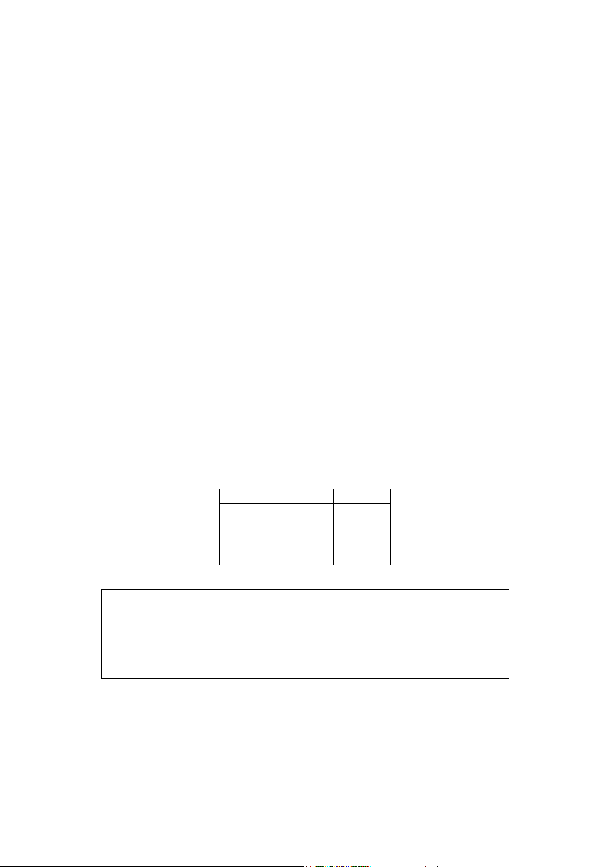
Table 1: Number of User-Refs Being Sent
Device ID bit 6 Device ID bit 5 Num User-Refs
000
011
102
113
Note: If the Z4/Z8/MPC4000 is set to have a user-selectable DeviceID of zero (0), then it will
respond to all SysEx messages regardless of the DeviceID transmitted. Similarly, if a DeviceID
of zero is transmitted by the controller (i.e., bits 0–4 = 0), all Z4/Z8/MPC4000s will respond
regardless of which DeviceID is set.
For non-zero DeviceIDs, the sampler will only respond to SysEx messages if its DeviceID
matches that sent.
User-Refs <0..&7F {0..127}>
The User-Ref parameters can be set to any value. It is only useful when confirmation messages are enabled
(or if a
REPLY is requested) where the User-Ref parameter is echoed with every confirmation message. This
is to allow flexibility in the design of control software where each SysEx message can be stamped with an ID
Version 1·50 © 2002–2004 AKAI professional M.I. Corp. Page 3/52

AKAI professional Z4/Z8/MPC4000 MIDI System Exclusive Protocol Specification
so that the confirmation messages can be matched to the commands sent. This is especially useful if the
control software sends buffered messages out-of-sequence.
Either 0, 1, 2, or 3 User-Refs can be sent with any message. To allow for this, the top 2 bits of the DeviceID
contain a count of the number of User-Refs which will be sent. The default number of User-Refs is 0: see
Table 1 for more details.
In this document, optional User-Refs will be shown as:
<…>.
Checksums
The checksum provides a means of error-detection in the SysEx message. The checksum is a single data byte
sent as the last item before the End-of-SysEx byte <&F7{247}>. By default, checksums are disabled making
sending SysEx messages as simple as possible. Enabling and disabling of checksums can only be done via
SysEx messages.
Note that because the SysEx specification for the Z4/Z8/MPC4000 supports a variable number of parameters,
if checksums are disabled, the calculated checksums may still be transmitted; although they will be ignored.
A checksum calculation begins at the first User-Ref byte (if any) — there is no point in calculating the
checksum earlier than this because if an error occurs in the first bytes, the SysEx message will be ignored
anyway — and the calculation stops before the End-of-SysEx byte.
To calculate the checksum, unsigned 8-bit addition is used, which wraps on overflow (i.e., 255+1 = 0). To
ensure compatibility with the
MIDI data byte specification, the high-bit of the checksum is set to zero (logical
AND with &7F{127}) once the checksum has been calculated.
For example, given the following SysEx message:
<&F0> <&47> <&5F> <&05> <&10> <&0C> <&1B> <&35> <&6D> <&F7>
{<240> <71> <95> <5> <16> <12> <27> <53> <109> <247>}
The checksum would be calculated as:
(&10 + &0C + &1B + &35 + &6D) = &D9 -> (&D9 AND &7F) = &59
{(16 + 12 + 27 + 53 + 109) = 217 -> (217 AND 127) = 89}
And the new checksummed message would be:
<&F0> <&47> <&5F> <&05> <&10> <&0C> <&1B> <&35> <&6D> <&59> <&F7>
{<240> <71> <95> <5> <16> <12> <27> <53> <109> <89> <247>}
A useful tip — to turn off Checksums on all Z4/Z8/MPC4000s, regardless of DeviceID, send:
<&F0> <&47> <&5F> <&00> <&00> <&04> <&00> <&04> <&F7>
{<240> <71> <95> <0> <0> <4> <0> <4> <247>}
A complete message
The format of a complete control message is as follows:
<&F0> <&47> <&5F> <0..&7F> <…> <Section> <Item> <Data1> … <DataN> <checksum> <&F7>
This allows the selection of various Sections, such as “Multi”, “Sample”, “Program”, “Config”, and the
variable number of data parameters allows the efficient passing of strings (which, for example, are used to
name programs, multis, etc.). The Section numbers are detailed in Table 4.
If extensive use is made of the System Exclusive protocol, it is recommended that checksums are
enabled so that transmission errors can be detected and handled.
Page 4/52 © 2002–2004 AKAI professional M.I. Corp. Version 1·50

AKAI professional Z4/Z8/MPC4000 MIDI System Exclusive Protocol Specification
Confirmation Messages
The confirmation message is a 7 or more byte SysEx message:
<&F0> <AKAI ID> <Z4/Z8 ID> <Device ID> <User-Ref…> <Reply ID> <Section> <Item> <Data1> …
The first 6 bytes (or more if <User-Refs> are used) are the same as those transmitted in the original message,
except that the
<Reply ID> item has been inserted. This format ensures that confirmation messages from
different devices can be distinguished, and the insertion of the
messages are not confused with other SysEx messages. Moreover, the
be used by a controlling computer to determine which SysEx message generated the confirmation message.
The values of Reply ID and Data1 … DataN are explained in Table 2. Note that the
sent if checksums are enabled (see Table 6).
Table 2: SysEx Confirmation Messages
Reply ID Data1 Data2 Meaning
&4F{79} ‘O’
&44{68} ‘D’
&52{82} ‘R’ Reply Type Reply 1… “
&45{69} ‘E’ <
NA NA “OK” Valid SysEx has been received and is being processed.
NA NA “DONE” SysEx instruction has been completed successfully.
LSB 0–127> <MSB 0–127> “ERROR” An error has occurred, Error Number = Data1 + 128×Data2
<DataN> <checksum> <&F7>
<Reply ID> item ensures that confirmation
<User-Ref>, <Section> and <Item> can
<checksum> will only be
REPLY” A variable number of bytes is returned as a reply (data
returned depends on SysEx message sent). Every piece of reply data
is preceded with a single
making it easier to interpret the data received.
The values of these
ID byte indicating the type of data following,
ID bytes are shown in Table 5.
Note that because the user-selectable DeviceID is returned in these messages, a controller can establish the
number of devices and their DeviceIDs connected in a chain by using the “Query” SysEx command with the
DeviceID set to be zero (all devices), which will return an “
the chain. The DeviceID will also have it’s top 2 bits set to show how many
the message (see Table 1 for more information). The number of and the values of
OK” and a “DONE” message from each sampler in
<User-Ref> bytes are included in
<User-Ref> bytes in the
confirmation message will always be the same as those in the message which caused the confirmation
message to be generated.
The normal flow of confirmation messages is that the “
OK” message will be transmitted as soon as a valid
Sysex message (i.e., manufacturer = &47{71}, model = &5F{95}, DeviceID = set value) has been received.
If there is an error in this message, or the message is unsupported, then the “
ERROR” confirmation message
will be returned—possible error numbers are explained in Table 3. If the message is supported, the function
will be performed then, once processing is complete, the “
Alternatively, if a request for information was issued, the “
message with the appropriate data contained within it. Note that it is possible, but unlikely, that a “
message may be followed by an “
ERROR” message if an error occurred during the generation of the reply.
DONE” confirmation message will be transmitted.
DONE” message will be replaced by a “REPLY”
REPLY”
Note: Although “OK”, confirmation messages can be turned on and off via SysEx, the “DONE”
“
REPLY” and “ERROR” messages cannot. This is to ensure that at least one message is returned for
every SysEx message received; thus making synchronisation of a controller easier.
Version 1·50 © 2002–2004 AKAI professional M.I. Corp. Page 5/52
AKAI professional Z4/Z8/MPC4000 MIDI System Exclusive Protocol Specification
Table 3: Error Numbers Returned
Error Number MSB LSB Description of Error
General Errors
&00{0} 0 0 The <Section> <Item> supplied are not supported
&01{1} 0 1 Checksum invalid
&02{2} 0 2 Unknown error
&03 {3} 0 3 Invalid message format
&04 {4} 0 4 Parameter out of range
&05{5} 0 5 Operation is pending
System Errors
&80{128} 1 0 Unknown system error
&81{129} 1 1 Operation had no effect
&82 {130} 1 2 Fatal error
&83{131} 1 3
&84{132} 1 4
Item Errors
&100{256} 2 0 Unknown item error
&101{257} 2 1 Item not found
&102{258} 2 2 Item in use
&103{259} 2 3 Invalid item handle
&104{260} 2 4 Invalid item name
&105{261} 2 5 Maximum number of items of a particular type reached
&120{288} 2 32 Keygroup not found
Disk Errors
&180{384} 3 0 Unknown disk error
&181{385} 3 1 No Disks
&182{386} 3 2 Disk is invalid
&183{387} 3 3 Load error
&184{388} 3 4 Create error
&185{389} 3 5 Directory not empty
&186{390} 3 6 Delete error
&187{391} 3 7 Disk is write-protected
&188{392} 3 8 Disk is not writable
&189{393} 3 9 Disk full
&18A{394} 3 10 Disk abort
File Errors
&200{512} 4 0 Unknown file error
&201{513} 4 1 File format is incorrect
CPU memory is full
WAVE memory is full
Page 6/52 © 2002–2004 AKAI professional M.I. Corp. Version 1·50

AKAI professional Z4/Z8/MPC4000 MIDI System Exclusive Protocol Specification
Table 3: Error Numbers Returned
Error Number MSB LSB Description of Error
&202{514} 4 2 WAV format is incorrect
&203{515} 4 3 File not found
&204{516} 4 4 File already exists
Control Messages
The functions of the Z4/Z8/MPC4000 which can be controlled via SysEx are grouped into Sections. For
example, there is a section to configure a Multi, and a section to change the
Sections then have several functions associated with them, called an Item. Thus each SysEx control message
consists of the appropriate device header:
<&F0> <AKAI ID> <Z4/Z8 ID> <Device ID> <User-Ref…>
then the Section and Item number:
<Section> <Item>
followed by the appropriate data for that command. The defined Sections are shown in Table 4.
MIDI configuration. These
Table 4: Description of <Section> Parameter
<Section> Description of Section
&00{0} SysEx Configuration
&04{4} System Setup
&0C{12} Keygroup Zone Manipulation
&10{16} Keygroup Manipulation
&14{20} Program Manipulation
&18{24} Multi Manipulation
&1C{28} Sample Tools
&20{32} Disk Tools
&24{36} Multi FX Control
&28{40}
&2C{44} Front Panel Control
&30{48} Recording
&44{68} <Reserved>
&45{69} <Reserved>
&4F{79} <Reserved>
&52{82} <Reserved>
&60{96}
&61{97}
&62{98}
&63{99}
&64{100}
a
a
a
a
a
Alternative (by-HANDLE) Sample Tools
Alternative (by-HANDLE ) Keygroup Zone and Keygroup
Alternative (by-HANDLE ) Multi FX Control
MIDI song file tools
Alternative (by-HANDLE) Program
Alternative (by-HANDLE ) Multi
Version 1·50 © 2002–2004 AKAI professional M.I. Corp. Page 7/52

AKAI professional Z4/Z8/MPC4000 MIDI System Exclusive Protocol Specification
Table 4: Description of <Section> Parameter
<Section> Description of Section
&65{101}
&68{104}
&69{105}
a
Alternative (by-HANDLE) Song File Control
b
b
a. These represent an alternative means of control, where the
operation is performed on the item (Multi, Program or Sample)
specified by handle, rather than on the currently selected item.
b. These operations are intended for automation of Program
parameters during playback of a sequencer. Any Program,
Keygroup, or Keygroup Zone parameter can be modified for any
part in the current Multi.
Keygroup and Zone Automation
Program Automation
Page 8/52 © 2002–2004 AKAI professional M.I. Corp. Version 1·50

AKAI professional Z4/Z8/MPC4000 MIDI System Exclusive Protocol Specification
Format of Message Data
The Z4/8 SysEx protocol supports variable-length messages, making it both flexible and adaptable.
Therefore, it is possible to send differently formatted data depending on the function to be performed and in
some cases, more than one piece of data is required in a single message. The format of the data required in
the messages should be strictly followed to avoid problems — although in most cases, an incorrect message
will simply generate an
Note
: Data bytes sent within SysEx messages must not exceed a value of 127 (or &7F). This
limitation is imposed by the
ERROR confirmation message.
MIDI specification. Failure to observe this limit may lead to undefined
behaviour!
Numeric data is always sent as 7-bit bytes (i.e., the top bit of each byte must be zero). Numbers which require
more than one byte to represent them are always sent least-significant byte first. Character strings can be any
length, but must always have a terminating character of value zero. A summary of all the data types is given
in Table 5. Note that the data format
ID is the value returned with every piece of reply data in confirmation
messages, a feature which makes automatic decoding of replies easier.
Table 5: SysEx Data Formats
Name ID Byte Format Description (Range)
BYTE 1 <value> byte (0–127)
SBYTE 2 <sign><value> signed byte (±127)
WORD 3<LSB><MSB> word (0–16383)
SWORD 4<sign><LSB><MSB> signed word (±16383)
DWORD 5<LSB><SB1><SB2><MSB> double word (0–268,435,455)
SDWORD 6<sign><LSB><SB1><SB2><MSB> signed double word (±268,435,455)
QWORD 7<B1><B2><B3><B4><B5><B6><B7><B8> quad word (0–72,057,594,037,927,935)
SQWORD 8<sign><B1><B2><B3><B4><B5><B6><B7><B8> signed quad word (±72,057,594,037,927,935)
STRING 9 <char1><char2>…<charN><0> Null-terminated string
BYTES 10 <value1><value2> 2 data bytes (command-specific)
2
3
BYTES 11 <value1><value2><value3> 3 data bytes (command-specific)
CUSTOM 32 specific to command Custom data (command-specific)
a. <sign>: 0 = positive, 1 = negative.
a
Arrays
If an array of values is to be sent, this is indicated by [n] following the data type. For example, an array of
signed bytes with 10 entries would be shown as
SBYTE[10].
Use of Ellipsis
The ellipsis, “…”, is used to illustrate that more data may be transmitted than the explicit data values shown
in the tables. For example, <Data1>…<DataeN> means that there may be additional bytes between Data1 and
DataN. The number of additional bytes depends on the both format and the content of the data being sent.
Version 1·50 © 2002–2004 AKAI professional M.I. Corp. Page 9/52

AKAI professional Z4/Z8/MPC4000 MIDI System Exclusive Protocol Specification
Item List for SysEx Configuration section [&00{0}]
These options control how the sampler responds to SysEx messages. These options only apply to the
MIDI
port on which the SysEx command was sent. This allows different applications to coexist on different ports
without interfering with the other’s communications. For example, problems would arise if port A disabled
checksums when port B required them.
To ensure that operations on one port do not interfere with those on another, LCD
Note:
synchronisation should be turned off when it is not essential (e.g., if editing a program) and only
used when required, e.g., when selecting the current multi to be played.
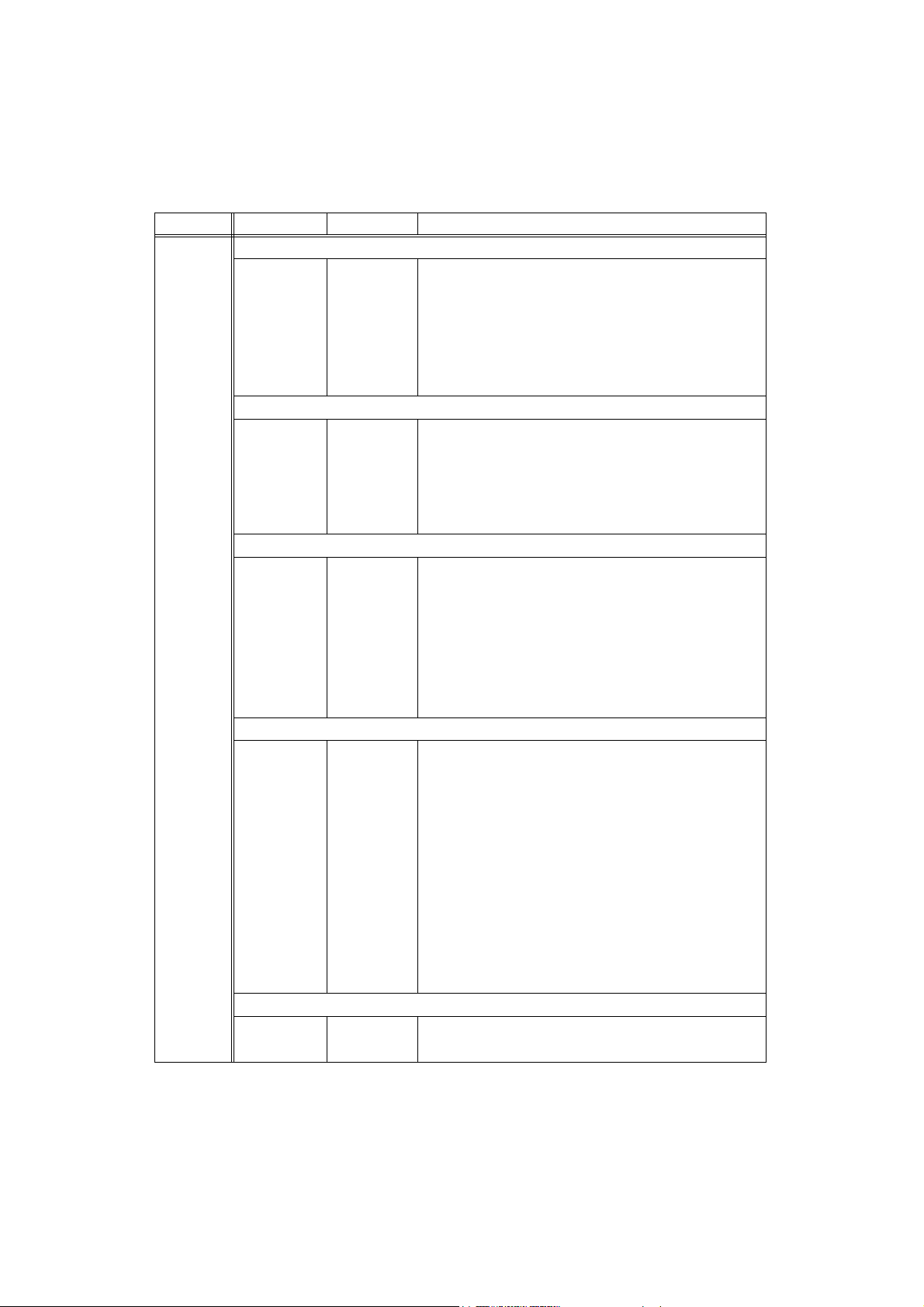
Table 6: Control Items for Section &00{0} — SysEx Configuration
<Item> <Data1> <Data2> Description of Item
&00{0}
RT
&01{1}
RT
&03{3}
&04{4}
&05{5}
&06{6}
&07{7}
b
RT
RT
RT
RT
d
RT
&08{8} BYTE(0, 1) NA Enable/Disable synchronisation between the current playback item
&10{16}
RT
a. The state of this option at power-on is ON.
b. Note that if synchronisation is enabled and the current muti, program or sample is changed by SysEx on a different port which also
has synchronisation enabled, the currently selected item on the current port will also change because the item displayed on the
will have changed. To avoid this situation, synchronisation should be turned off, and enabled only when required.
c. The state of this option at power-on is OFF.
d. Some SysEx messages may require substantial time to execute. This can result in large delays between an OK and a DONE (or REPLY/
ERROR) message which the host could interpret as “samper not responding”. To avoid this, if the Still Alive monitor is enabled, a NULL
message (<&F0><&F7>) will be transmitted to the host approximately every second, whilst the host is awaiting a response.
NA NA “Query” — use with user-selectable DeviceID=0 to get an “OK!” and
a “DONE” reply with DeviceID returned
BYTE(0, 1) NA Enable/Disable received message notification (“OK!”)
<Data1> = (0=
BYTE(0, 1) NA Enable/Disable synchronisation between the currently selected
OFF, 1=ON)
samples/programs/multis and those displayed on the front-panel
<Data1> = (0=
BYTE(0, 1) NA Enable/Disable checksum verification <Data1> = (0=OFF, 1=ON)
BYTE(0, 1) NA Enable/Disable automatic screen updating when a SysEx message is
OFF, 1=ON)
processed <Data1> = (0=
BYTE BYTE,
BYTE,
BYTE
BYTE(0, 1) NA Enable/Disable “Still Alive” monitor <Data1> = (0=OFF, 1=ON)
Echo Message: a special test function which will echo all 4 data bytes
by returning them as a Reply. This is useful when debugging a
controlling program.
and the playback item selected on the front-panel
<Data1> = (0=
NA NA Get SysEx Buffer Size
OFF, 1=ON)
a
a
OFF, 1=ON)
a
c
c
LCD
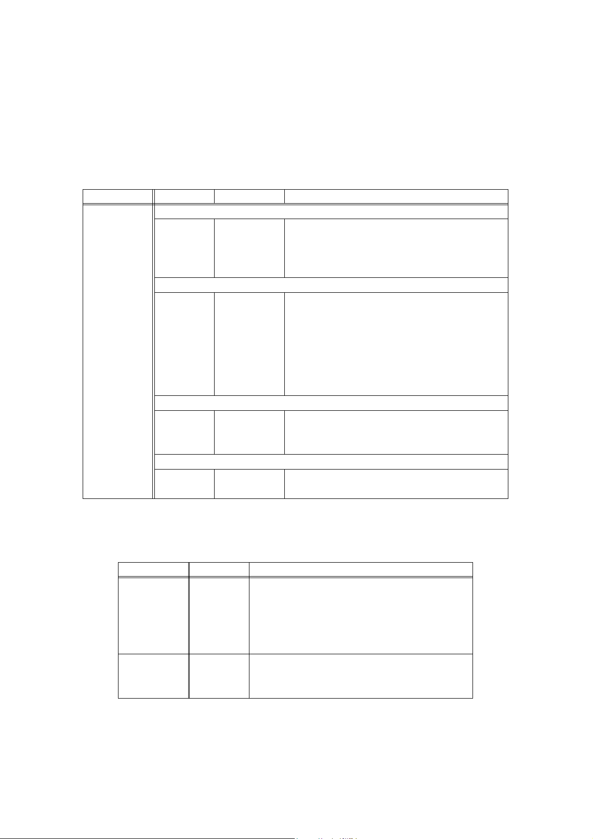
Table 7: Format of “REPLY” confirmation messages for Section &00 {0} — SysEx
Configuration
<Item> requested <Reply>… Description of Data Returned
&10 {16}
WORD Get SysEx Buffer Size
Page 10/52 © 2002–2004 AKAI professional M.I. Corp. Version 1·50
AKAI professional Z4/Z8/MPC4000 MIDI System Exclusive Protocol Specification
Item List for System Setup section [&04 {4}]
This System section contains several general settings which control the behaviour of the sampler.
When information about the System Setup is requested with a Get message, the data is returned in a “
REPLY”
confirmation message (see Confirmation Messages on page 5). The format of these messages is summarised
in Table 9 and Table 11.
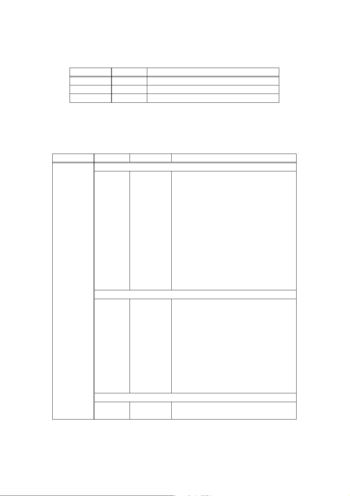
Table 8: Control Items for Section &04{4} — System Main
<Item> <Data1> <Data2> Description of Item
General
&00{0}
&01{1}
&04{4}
&08{8}
&10{16}
&11{17}
&12{18}
&13{19}
&18{24}
&19{25}
&1A{26}
&20{32}
&21{33}
&22{34}
&30{48}
&31{49}
NA NA Get Operating System Software Version
NA NA Get the Sub-Version of the Operating System
NA NA Get Sampler Model
NA NA Get List of supported filetypes
Memory Information
NA NA Get the percentage free Wave memory
NA NA Get the percentage free CPU memory
NA NA Get the total number of kilobytes of Wave memory
NA NA Get the number of kilobytes of free Wave memory
NA NA Clear Sampler Memory (delete all items from memory)
BYTE NA Purge Unused Items <Data1> = (0=SAMPLE, 1=PROGRAM)
BYTE NA Tag Unused Items <Data1> = (0=SAMPLE, 1=PROGRAM)
Wave Memory Compacting Functions
NA NA Start Compact Wave Memory
NA NA Cancel Compact Wave Memory
NA NA Get Compact Wave Memory Progress (%)
Asynchronous Operation Control
NA NA Get State of Asynchronous Operation
NA NA Cancel Current Asynchronous Operation
Table 9: Format of “REPLY” confirmation messages for Section &04 {4} — System Main
<Item> requested <Reply>… Description of Data Returned
&00{0} 2
BYTES Operating System Version: <Value1>=major version number,
<Value2>=minor version number
&01{1} BYTE Operating System Sub-Version
&04{4}
&08{8}
BYTE(0 – 2) Sampler Model <Reply1> = (0=Z4, 1=Z8, 2=MPC4000)
STRING[] Get List of supported filetypes
<Reply…> contains a list of file extensions which are supported
&10{16} BYTE Get the percentage free Wave memory
&11{17}
BYTE Get the percentage free CPU memory
&12{18} DWORD Get the total number of kilobytes of Wave memory
Version 1·50 © 2002–2004 AKAI professional M.I. Corp. Page 11/ 52
AKAI professional Z4/Z8/MPC4000 MIDI System Exclusive Protocol Specification
Table 9: Format of “REPLY” confirmation messages for Section &04 {4} — System Main
<Item> requested <Reply>… Description of Data Returned
&13{19} DWORD Get the number of kilobytes of free Wave memory
&22 {34}
&30 {48} (see footnote
BYTE Get Compact Wave Memory Progress (%)
a
) Get State of Asynchronous Operation
a. If the asynchronous operation is complete, a DONE confirmation m essage will be returned. If the operation is still
pending, an
ERROR confirmation message will be returned with the error “Operation is pending”.
Table 10: Control Items for Section &06{6} — System Parameter Set
<Item> <Data1> <Data2>… Description of Item
Global Options
a
&01{1}
&02{2}
&03{3} SWORD
&04{4} BYTE(0–7) NA Set Master Level <Data1> = (−42dB – 0dB in 6dB steps)
&05{5} BYTE(0, 1) BYTE(0, 2) Set MIDI OUT/THRU
&06{6}
&07{7}
&08{8}
&09{9}
&0A{10}
&10{16}
&11{17}
&12{18}
&13{19}
&14{20}
&18{24}
&19{25}
&1A{26}
&1B{27}
&20{32}
&21{33}
STRING NA Set Sampler Name
BYTE(0–7) NA Set SCSI self ID
NA Set Master Tune
(0–±3600)
(0=−42dB, 1=−36dB, …, 7=0 dB)
<Data1> =
<Data2> = (0=
BYTE(0, 1) NA Set Qlink Local Control <Data1> = (0=OFF, 1=ON)
BYTE(0, 1) NA Set Create Default Items at Startup <Data1> = (0=OFF, 1=ON)
BYTE(0, 1) NA Set MIDI file save format
BYTE(0–7) NA Set CD-R write speed <Data1> =
(0=×1, 1=×2, 2=×4, 3=×6, 4=×8, 5=×12, 6=×16, 7=
BYTE(0–2) NA Set CD-R write mode
<Data1> = (0=
TEST+WRITE, 1=TEST ONLY, 2=WRITE ONLY)
MIDI port (0=A, 1=B),
OUT, 1=THRUA, 2=THRUB)
MAX)
Display Options
BYTE(0, 1) NA Set Front panel lock-out state
<Data1> = (0=
BYTE(0–19) NA Set Display Contrast
BYTE(0, 1) NA Set Note Display <Data1> = (0=NUMBER, 1=NAME)
BYTE(0–3) NA Set Date Display Format
<Data1> = (0=
BYTE(0, 1) NA Set Time Display Format
<Data1> = (0=12
BYTE(0, 1) NA Set Waveform View Scale <Data1> = (0=LINE AR, 1=LOG)
BYTE(0, 1) NA Set Waveform View Type <Data1> = (0=RECTIFIED, 1=BIPOLAR)
BYTE(0, 1) NA Set Waveform View Fill <Data1> = (0=OFF, 1=ON)
BYTE(0, 1) NA Set Item Sort Mode <Data1> = (0=ALPHABETIC, 1=MEMORY)
NORMAL; 1=LOCKED)
DDMMYY, 1=MMDDYY, 2=YYMMDD)
HOUR, 1=24HOUR)
Time and Date
BYTE NA Set Year
BYTE NA Set Month
Page 12/52 © 2002–2004 AKAI professional M.I. Corp. Version 1·50

AKAI professional Z4/Z8/MPC4000 MIDI System Exclusive Protocol Specification
Table 10: Control Items for Section &06{6} — System Parameter Set
<Item> <Data1> <Data2>… Description of Item
&22{34} BYTE NA Set Day
&23{35}
&24{36}
&25{37}
&26{38}
&30{48}
&31{49}
&32{50}
&33{51}
&40{64}
&41{65}
&42{66}
&48{72}
&49{73}
&4A{74}
&4B{75} BYTE(0, 1) NA Set Play Key Echo <Data1> = (0=OFF, 1=ON)
&4C{76}
&4D{77}
&50{80} BYTE(0, 1) NA Set Global Pad Mode <Data1> = (0=DEFAULT, 1=CHROMATIC)
&51{81} BYTE(0–15) NA Set MIDI Channel
&52{82}
&53{83}
&54{84}
BYTE NA Set Day of Week (0=SUN)
BYTE NA Set Hours
BYTE NA Set Minutes
BYTE NA Set Seconds
Digital Options
BYTE(0, 1) NA Set System Clock <Data1> = (0=44·1 kHz, 1=48 kHz, 2=96kHz)
BYTE(0–3) NA Set Digital Out Sync
<Data1> = (0=
BYTE(0, 1) NA Set Digital Format <Data1> = (0=PRO, 1=CONSUMER)
BYTE(0, 1) NA Set ADAT Main Out <Data1> = (0=L/R, 1=1/2)
INTERNAL, 1=DIGITAL IN, 2=ADAT IN,
WORDCLOCK)
3=
Play Functions
BYTE(0–3) DWORD Set Play Mode
<Data1> = (0=Multi, 1=Program; 2=Sample; 3=Muted)
<Data2> = handle of item to become active Play Item
BYTE(0, 1) NA Set Program Monitor Mode
<Data1> = (0=Multi, 1=Program(
BYTE(0–2) NA Set Sample Monitor Mode
<Data1> = (0=Multi, 1=Program; 2=Sample(
BYTE NA Set Play Key Note
BYTE NA Set Play Key Velocity
BYTE (0–31) NA Set Play Key Midi Channel
OMNI))
OMNI))
<Data1> = (1A=0, 2A=1, …, 16B=31)
BYTE(0, 1) NA Set Program Change Enable <Data1> = (0=OFF, 1=ON)
BYTE(0, 1) NA Set Autoload Enable <Data1> = (0=OFF, 1=ON)
MPC Pad Setup
BYTE(0–15) BYTE(0–100) Set Pad Sensitivity <Data1> = Pad
b
<Data2> = Sensitivity (0 –100 = 100% – 200%)
BYTE(0–95) BYTE Set Default Note Assignment <Data1> = Pad, <Data2> = Note
BYTE NA Set Chromatic Start Note
a. Unless this is changed by the user, the default value will be returned: either “Z4 Sampler”, “Z8 Sampler” or “MPC4000”. This is an
alternative way of remotely identifying samplers.
b. This is currently only supported by the MPC4000.
Version 1·50 © 2002–2004 AKAI professional M.I. Corp. Page 13/ 52

AKAI professional Z4/Z8/MPC4000 MIDI System Exclusive Protocol Specification
Table 11: Control Items for Section &07 {7} — System Parameter Get
<Item> <Data1>… <Reply>… Description of Item
Global Options
&01{1}
&02{2}
&03{3} NA SWORD
&04{4}
&05{5} BYTE(0, 1) BYTE(0, 2) Get MIDI OUT/THRU
&06{6}
&07{7}
&08{8}
&09{9}
&0A{10}
&10{16}
&11{17}
&12{18}
&13{19}
&14{20}
&18{24}
&19{25}
&1A{26}
&1B{27}
&20{32}
&21{33}
&22{34}
&23{35}
&24{36}
&25{37}
&26{38}
&30{48}
NA STRING Get Sampler Name
NA BYTE(0–7) Get SCSI self ID
Get Master Tune
(0–±3600)
NA BYTE(0 – 7) Get Master Level <Reply> = (−42dB – 0dB in 6 dB steps)
(0=−42dB, 1=−36 dB, …, 7=0dB)
<Data1> =
<Reply> = (0=
NA BYTE(0, 1) Get Qlink Local Control <Reply> = (0=OFF, 1=ON)
NA BYTE(0, 1) Get Create Default Items at Startup <Reply> = (0=OFF, 1=ON)
NA BYTE(0, 1) Get MIDI file save format
NA BYTE(0–7) Set CD-R write speed <Reply> =
MIDI port (0=A, 1=B),
OUT, 1=THRUA, 2=THRUB)
(0=×1, 1=×2, 2=×4, 3=×6, 4=×8, 5=×12, 6=×16, 7=
NA BYTE(0– 2) Set CD-R write mode
<Reply> = (0=
TEST+WRITE, 1=TEST ONLY, 2=WRITE ONLY)
Display Options
NA BYTE(0, 1) Get Front panel lock-out state
<Reply> = (0=
NA BYTE(0–19) Get Display Contrast
NA BYTE(0, 1) Get Note Display <Reply> = (0=NUMBER, 1=NAME)
NA BYTE(0–3) Get Date Display Format
<Reply> = (0=
NA BYTE(0, 1) Get Time Display Format
<Reply> = (0=12
NA BYTE(0, 1) Get Waveform View Scale <Reply> = (0=LINEAR, 1=LOG)
NA BYTE(0, 1) Get Waveform View Type <Reply> = (0=RECTIFIED, 1=BIPOLAR)
NA BYTE(0, 1) Get Waveform View Fill <Reply> = (0=OFF, 1=ON)
NA BYTE(0, 1) Get Item Sort Mode <Reply> = (0=ALPHABETIC, 1=MEMORY)
NORMAL; 1=LOCKED)
DDMMYY, 1=MMDDYY, 2=YYMMDD)
HOUR, 1=24HOUR)
Time and Date
NA BYTE Get Year
NA BYTE Get Month
NA BYTE Get Day
NA BYTE Get Day of Week (0=SUN)
NA BYTE Get Hours
NA BYTE Get Minutes
NA BYTE Get Seconds
Digital Options
NA BYTE(0, 1) Get System Clock <Reply> = (0=44·1 kHz, 1=48kHz, 2=96 kHz)
MAX)
Page 14/52 © 2002–2004 AKAI professional M.I. Corp. Version 1·50

AKAI professional Z4/Z8/MPC4000 MIDI System Exclusive Protocol Specification
Table 11: Control Items for Section &07 {7} — System Parameter Get
<Item> <Data1>… <Reply>… Description of Item
&31{49} NA BYTE(0– 3) Get Digital Out Sync
<Reply> = (0=
&32{50}
&33{51}
NA BYTE(0, 1) Get Digital Format <Reply> = (0=PRO, 1=CONSUMER)
NA BYTE(0, 1) Get ADAT Main Out <Reply> = (0=L/R, 1=1/2)
Play Functions
&40{64}
NA BYTE(0– 3)
DWORD
<Reply1> = (0=Multi, 1=Program; 2=Sample; 3=Muted)
<Reply2> = handle of item which is the active Play Item
&41{65}
NA BYTE(0, 1) Get Program Monitor Mode
<Reply1> = (0=Multi, 1=Program(
&42{66}
NA BYTE(0–2) Get Sample Monitor Mode
<Reply1> = (0=Multi, 1=Program; 2=Sample(
&48{72}
&49{73}
&4A{74}
&4B{75}
&4C{76}
&4D{77}
NA BYTE Get Play Key Note
NA BYTE Get Play Key Velocity
NA BYTE (0–31) Get Play Key Midi Channel
NA BYTE (0, 1) Get Play Key Echo <Reply> = (0=OFF, 1=ON)
NA BYTE (0, 1) Get Program Change Enable <Reply> = (0=OFF, 1=ON)
NA BYTE (0, 1) Get Autoload Enable <Reply> = (0=OFF, 1=ON)
MPC Pad Setup
&50{80} NA BYTE(0, 1) Get Global Pad Mode <Reply> = (0=DEFAULT, 1=CHROMATIC)
&51{81}
&52{82}
NA BYTE(0–15) Get MIDI Channel
BYTE(0–15) BYTE(0– 100) Get Pad Sensitivity <Data1> = Pad
<Reply> = Sensitivity (0–100 = 100%–200%)
&53{83} BYTE(0–95) BYTE Get Default Note Assignment <Data1> = Pad, <Reply> = Note
&54{84}
NA BYTE Get Chromatic Start Note
INTERNAL, 1=DIGITAL IN, 2=ADAT IN,
WORDCLOCK)
3=
Get Play Mode
OMNI))
<Reply> = (1A=0, 2A=1, …, 16B=31)
a
OMNI))
a. This is currently only supported by the MPC4000.
Version 1·50 © 2002–2004 AKAI professional M.I. Corp. Page 15/ 52

AKAI professional Z4/Z8/MPC4000 MIDI System Exclusive Protocol Specification
Item List for the Keygroup Zones section [&0C{12}]
For convenience, Keygroup Zones have their own dedicated section, rather than being manipulated as part of
the Keygroup section. Unlike in many of the other sections, selection of a zone is not required before it can
be manipulated. Instead each of the zone manipulation functions includes the zone number as the first
parameter. The value of zone = 0 means
ALL zones, in which case all 4 zones will be updated simultaneously.
Note that zones always refer to the currently selected keygroup in the currently selected program. So if
another keygroup, or program, is to be adjusted the functions in the appropriate sections must be used to select
the desired keygroup or program.
Table 12: Control Items for Section &0E {14} — Keygroup Zone Set Parameter
<Item> <Data1>
<Data2>… Description of Item
(Zone number)
&01{1}
&02{2}
&03{3}
&04{4}
&05{5}
&06{6}
&07{7}
&08{8}
BYTE(0, 1–4) STRING Set Zone Sample <Data2…0> = name of sample to assign to zone.
BYTE(0, 1–4) SWORD(−600–+60) Set Zone Level <Data1> = level in 10×dB
RT
BYTE(0, 1–4) BYTE(0– 100) Set Zone Pan/Balance <Data2> = Pan/Bal, where
RT
BYTE(0, 1–4) BYTE(0 –15) Set Zone Output <Data2> = output, where
BYTE(0, 1–4) SBYTE(0– ±100) Set Zone Filter
RT
BYTE(0, 1–4) SWORD(0 – ±3600) Set Zone Cents Tune
RT
BYTE(0, 1–4) BYTE(0, 1) Set Zone Keyboard Track <Data2> = (0=OFF, 1=ON)
BYTE(0, 1–4) BYTE(0–6) Set Zone Playback <Data2> = mode, where
&09{9} BYTE(0, 1–4) SWORD
(0–±9999)
&0A{10}
&0B{11}
&0C{12}
&0D{13}
BYTE(0, 1–4) BYTE Set Zone Low Velocity
BYTE(0, 1–4) BYTE Set Zone High Velocity
BYTE(0, 1–4) BYTE(0, 1) Set Zone Mute <Data2> = (0=OFF, 1=ON)
RT
BYTE(0, 1–4) BYTE(0, 1) Set Zone Solo <Data2> = (0=OFF, 1=ON)
RT
Setting Zone Parameters
(0–100 = L50–R50); centre=&32{50}
MULTI, 1 = L/R; 2–5 = op1/2–op7/8; 6–15 = L, R, op1-op8
0=
NO LOOPING, 1=ONE SHOT 2=LOOP IN REL, 3=LOOP UNTIL REL,
0=
LIR→RETRIG, 5=PLAY→RETRIG, 6=AS SAMPLE
4=
Set Zone Mod→Start
Table 13: Control Items for Section &0F {15} — Keygroup Zone Get Parameter
<Item> <Data1>
(Zone number)
&01{1}
&02{2}
&03{3}
&04{4}
&05{5}
&06{6}
BYTE(0, 1–4) STRING Get Zone Sample
BYTE(0, 1–4) SWORD(−600 –+60) Get Zone Level <Reply> = level in 10×dB
BYTE(0, 1–4) BYTE(0– 100) Get Zone Pan/Balance
BYTE(0, 1–4) BYTE(0–15) Get Zone Output
BYTE(0, 1–4) SBYTE(0 – ±100) Get Zone Filter
BYTE(0, 1–4) SBYTE(0– ±3600) Get Zone Cents Tune
<Reply>… Description of Item
Getting Zone Parameters
Page 16/52 © 2002–2004 AKAI professional M.I. Corp. Version 1·50

AKAI professional Z4/Z8/MPC4000 MIDI System Exclusive Protocol Specification
Table 13: Control Items for Section &0F {15} — Keygroup Zone Get Parameter
<Item> <Data1>
&07{7} BYTE(0, 1–4) BYTE(0, 1) Get Zone Keyboard Track
&08{8}
&09{9}
&0A{10}
&0B{11}
&0C{12}
&0D{13}
(Zone number)
BYTE(0, 1–4) BYTE(0–6) Get Zone Playback
BYTE(0, 1–4) SWORD
BYTE(0, 1–4) BYTE Get Zone Low Velocity
BYTE(0, 1–4) BYTE Get Zone High Velocity
BYTE(0, 1–4) BYTE(0, 1) Get Zone Mute <Reply> = (0=OFF, 1=ON)
BYTE(0, 1–4) BYTE(0, 1) Get Zone Solo <Reply> = (0=OFF, 1=ON)
When information about a Keygroup Zone is requested with a Get message, the data is returned in a “
<Reply>… Description of Item
Get Zone Mod→Start
(0–±9999)
REPLY”
confirmation message (see Confirmation Messages on page 5). The format of the data content of these
messages is summarised in Table 13.
If the selected Zone is set to be 0 (zero), then the
REPLY message will contain additional data (one set for every
Zone in the current Keygroup). The format of this extra data is the same as that shown in Table 13 where the
set of data bytes is repeated four times (once for each Zone) in a single
REPLY confirmation message.
Version 1·50 © 2002–2004 AKAI professional M.I. Corp. Page 17/ 52

AKAI professional Z4/Z8/MPC4000 MIDI System Exclusive Protocol Specification
Item List for the Keygroup section [&10 {16}]
Although Keygroups are really part of a program, it is more convenient to edit them as separate entities.
Before a Keygroup can be used, it must be selected to be current. This is done using the Select Keygroup
function where the number of the keygroup is specified. Note that this keygroup always refers to the
appropriate keygroup in the currently selected program, so care must be taken to ensure that the current
keygroup remains valid when a different program is selected. All of the keygroups in a program can be edited
simultaneously by selecting keygroup edit mode to be
ALL or ADD. Note that, for convenience, Keygroup
Zones are manipulated using functions in the Keygroup Zone section.
When information about a Keygroup is requested with a Get message, the data is returned in a “
REPLY”
confirmation message (see Confirmation Messages on page 5). The format of the data content of these
messages is summarised in Table 17 and Table 15.
Table 14: Control Items for Section &10 {16} — Keygroup Main
<Item> <Data1> <Data2>… Description of Item
&01 {1}
&02 {2}
BYTE NA Select Keygroup to be current <Data1> = Keygroup number
NA NA Get Current Keygroup
Table 15: Format of “REPLY” confirmation messages for Section &10 {16} — Keygroup
<Item> requested <Data1> <Data2> Description of Data Returned
&02 {2}
BYTE NA Current Keygroup <Data1> = Keygroup number
Table 16: Control Items for Section &12 {18} — Keygroup Set Parameter
<Item> <Data1> <Data2>… Description of Item
Setting General Options
&01{1}
&02{2}
&04{4}
&05{5}
&06{6}
&07{7}
&08{8}
RT
&09{9} BYTE(0–2) NA Set Zone Crossfade <Data1> = (0=OFF, 1=VELOCITY, 2=REAL-TIME)
&0A{10}
&0E{14}
&0F{15}
BYTE NA Set Group ID
BYTE(0–2) NA Set Keygroup Edit Mode <Data2> = (0=SINGLE, 1=ALL, 2=ADD)
BYTE NA Set Low Note
BYTE NA Set High Note
BYTE(0, 1–64) NA Set Mute Group <Data1> = (0=OFF, 1–64=value)
BYTE(0, 1–4) NA Set FX override
SWORD
(−600–+60)
BYTE(0–2) NA Crossfade type <Data1> = (0=LIN, 1=EXP, 2=LOG)
BYTE(1–64) NA Set Polyphony
BYTE NA Set Zone Crossfade Source Controller Number
NA Set FX Send Level <Data1> = level in 10×dB
<Data1> = (0=
(only used when Zone Crossfade Source is
Set Keygroup Pitch/Amp
OFF, 1=A, 2=B, 3=C, 4=D, 5=AB, 6=CD, 7=MULTI)
MIDI CTRL)
Page 18/52 © 2002–2004 AKAI professional M.I. Corp. Version 1·50

AKAI professional Z4/Z8/MPC4000 MIDI System Exclusive Protocol Specification
Table 16: Control Items for Section &12 {18} — Keygroup Set Parameter
<Item> <Data1> <Data2>… Description of Item
&10{16}
&11{17}
&18{24}
&19{25}
&1A{26}
&20{32}
SBYTE(0 – ±3600) NA Set Cents Tune
RT
RT
SWORD NA Set Keygroup Level <Data1> = value in 10×dB
Set Keygroup Trigger
BYTE(0, 1) NA Set Play Trigger <Data1> = (0=NOTE ON, 1=NOTE OFF)
WORD(0–129) NA Set Play Trigger Velocity
<Data1> = (0=
BYTE(0, 1) NA Set Play Toggle Note <Data1> = (0=OFF, 1=ON)
Set Filter <Data1> = Filter block (0=
BYTE(0–3) BYTE(0–35) Set Filter Mode
NORMAL, 1=TRIPLE(1), 2=TRIPLE(2), 3=TRIPLE(3))
ORMAL mode, when <Data1> = 0;
N
POLE LP, 2=2-POLE LP +, 3=4-POLE LP, 4=4-POLE LP+,
1=2-
POLE LP, 6=2-POLE BP, 7=2-POLE BP+, 8=4-POLE BP,
5=6-
POLE BP+, 10=6-POLE BP, 11=1-POLE HP, 12=1-POLE HP +,
9=4-
POLE HP, 14=2-POLE HP+, 15=4-PO LE H P, 16=4-POLE HP+,
13=2-
LO<>HI, 19=LO<>BAND, 20=BAND<>HI, 21=NOTCH 1,
18=
NOTCH 2, 23=NOTCH 3, 24=WIDE NOTCH, 25=BI-NOTCH,
22=
PEAK 1, 27=PEAK 2, 28=PEAK 3, 29=WIDE PEAK, 30=BI-PEAK,
26=
PHASER 1, 32=PHASE R 2, 33=BI-PHASE, 34=VOWELISER,
31=
ON VEL, 1=OFF VEL, 2–129=0–127)
<Data2> = (0=
17=6-
35=
OFF,
POLE HP,
TRIPLE)
&21{33}
&22{34}
&23{35}
&30{48}
&31{49}
&32{50}
&33{51}
&34{52}
&35{53}
&36{54}
&37{55}
&42{66}
&43{67}
&50{80}
&51{81}
&52{82}
&53{83}
&54{84}
T
RIPLE mode, when <Data1> = 1–3;
<Data2> = (0=
OFF, 1=2-POLE LP, 2=1-POLE BP
3=1-POLE HP, 4=2-POLE HP, 5=NOTCH 1, 6=EQ, 7=EQ+)
RT
RT
RT
BYTE(0–3) BYTE(0–100) Set Filter Cutoff Frequency
BYTE(0–3) BYTE(0–64) Set Filter Resonance
BYTE(0–5) NA Set Filter Attenuation (one setting for all filters)
<Data1> = (0, 1, 2, 3, 4, 5 = 0 dB, 6 dB, 12 dB, 18dB, 24 dB, 30 dB)
Set Envelope <Data1> = Envelope (0=AMP, 1=FILTER, 2=AUX)
RT
RT
RT
RT
RT
RT
RT
RT
RT
RT
a
RT
a
RT
RT
RT
RT
BYTE(0–2) BYTE(0–100) Set Envelope Rate 1 (for AMP = Attack)
BYTE(0–2) BYTE(0–100) Set Envelope Level 1 (FILTER and AUX only)
BYTE(0–2) BYTE(0–100) Set Envelope Rate 2 (for AMP = Decay)
BYTE(0–2) BYTE(0–100) Set Envelope Level 2 (for AMP = Sustain)
BYTE(0–2) BYTE(0–100) Set Envelope Rate 3 (for AMP = Release)
BYTE(0–2) BYTE(0–100) Set Envelope Level 3 (FILTER and AUX only)
BYTE(0–2) BYTE(0–100) Set Envelope Rate 4 (FILTER and AUX only)
BYTE(0–2) BYTE(0–100) Set Envelope Level 4 (FILTER and AUX only)
BYTE(0–2) BYTE(0–100) Set Envelope Reference (FILTER and AUX only)
BYTE(0–2) BY TE(0, 1) Set Attack Hold <Data1> = (0=OFF, 1=ON) (AMP only)
LFOs — Set Values. <Data1> =
BYTE(0, 1) BYTE(0–100) Set LFO Rate <Data2> = rate
BYTE(0, 1) BYTE(0–100) Set LFO Delay <Data2> = delay
BYTE(0, 1) BYTE(0–100) Set LFO Depth <Data2> = depth
BYTE(0, 1) BYTE(0–8) Set LFO Waveform <Data2> = waveform, (see Table 23)
BYTE(0, 1) WORD(0–360) Set LFO Phase
LFO (0=LFO1, 1=LFO2)
Version 1·50 © 2002–2004 AKAI professional M.I. Corp. Page 19/ 52

AKAI professional Z4/Z8/MPC4000 MIDI System Exclusive Protocol Specification
Table 16: Control Items for Section &12 {18} — Keygroup Set Parameter
<Item> <Data1> <Data2>… Description of Item
&55{85}
&56{86}
&57{87}
RT
RT
RT
BYTE(0, 1) SBYTE(0–±50) Set LFO Shift
BYTE(0, 1) BYTE(0, 1) Set LFO MIDI Sync <Data2> = (0=OFF, 1=ON)
BYTE(0, 1) BYTE(0–68) Set MIDI Clock Sync Division <Data2> = value, where
0=8cy/bt, 1=6 cy/bt, 2=4 cy/bt, 3=3cy/bt, 4=2 cy/bt, 5=1 cy/bt
6=2bt/cy, 7=3bt/cy, …, 68=64 bt/cy
&58{88}
RT
&59{89}
RT
a. The LFO Rate and Delay settings are only valid if the LFO is not synchronised to MIDI clock.
BYTE(0, 1) BYTE(0, 1) Set LFO Re-trigger <Data2> = (0=OFF, 1=ON)
BYTE(0, 1) BYTE(0, 1) Set LFO sync (i.e., all voices in program locked to same lfo)
Table 17: Control Items for Section &13 {19} — Keygroup Get Parameter
<Item> <Data1> <Reply>… Description of Item
Getting General Options
&01{1}
&02{2}
&04{4}
&05{5}
&06{6}
&07{7}
&08{8}
&09{9}
&0A{10}
&0E{14}
&0F{15}
&10{16}
&11{17}
&18{24}
&19{25}
&1A{26}
RT
RT
NA BYTE Get Group ID
NA BYTE(0– 2) Get Keygroup Edit Mode <Reply1> = (0=SINGLE, 1=ALL, 2=ADD)
NA BYTE Get Low Note
NA BYTE Get High Note
NA BYTE(0, 1–64) Get Mute Group <Reply1> = (0=OFF, 1–64=value)
NA BYTE(0, 1–4) Get FX override
<Reply1> = (0=
NA SWORD (−600–+60) Get FX Send Level <Reply1> = level in 10×dB
NA BYTE(0–2) Get Zone Crossfade
NA BYTE(0–2) Get Crossfade type <Reply1> = (0=LIN, 1=EXP, 2=LOG)
NA BYTE(1–64) Get Polyphony
NA BYTE Get Zone Crossfade Source Controller Number
(only used when Zone Crossfade Source is
OFF, 1=A, 2=B, 3=C, 4=D, 5=AB, 6=CD, 7=MULTI)
<Reply1> = (0=
OFF, 1=VELOCITY, 2=REAL-TIME)
MIDI CTRL)
Get Keygroup Pitch/Amp
NA SBYTE(0 – ±3600) Get Cents Tune.
NA SWORD Get Keygroup Level <Reply> = value in 10×dB
Set Keygroup Trigger
NA BYTE(0, 1) Get Play Trigger <Reply> = (0=NOTE ON , 1=NOTE OFF)
NA WORD(0–129) Get Play Trigger Velocity
<Reply> = (0=
NA BYTE(0, 1) Get Play Toggle Note <Reply> = (0=OFF, 1=ON)
Get Filter <Data1> = Filter block (0=
NORMAL, 1=TRIPLE(1), 2=TRIPLE(2), 3=TRIPLE(3))
ON VEL, 1=OFF VEL, 2–129=0–127)
Page 20/52 © 2002–2004 AKAI professional M.I. Corp. Version 1·50

AKAI professional Z4/Z8/MPC4000 MIDI System Exclusive Protocol Specification
Table 17: Control Items for Section &13 {19} — Keygroup Get Parameter
<Item> <Data1> <Reply>… Description of Item
&20{32} BYTE(0–3) BYTE(0–35) Get Filter Mode
1=2-
5=6-
POLE BP+, 10=6-POLE BP, 11=1-POLE HP, 12=1-POLE HP +,
9=4-
POLE HP, 14=2-POLE HP+, 15=4-PO LE H P, 16=4-POLE HP+,
13=2-
18=
NOTCH 2, 23=NOTCH 3, 24=WIDE NOTCH, 25=BI-NOTCH,
22=
PEAK 1, 27=PEAK 2, 28=PEAK 3, 29=WIDE PEAK, 30=BI-PEAK,
26=
PHASER 1, 32=PHASE R 2, 33=BI-PHASE, 34=VOWELISER,
31=
3=1-POLE HP, 4=2-POLE HP, 5=NOTCH 1, 6=EQ, 7=EQ+)
&21{33}
&22{34}
&23{35}
RT
RT
RT
BYTE(0–3) BYTE(0–100) Get Filter Cutoff Frequency
BYTE(0–3) BYTE(0–64) Get Filter Resonance
NA BYTE(0–5) Get Filter Attenuation (one setting for all filters)
<Reply> = (0, 1, 2, 3, 4, 5 = 0 dB, 6 dB, 12 dB, 18dB, 24 dB, 30 dB)
Get Envelope <Data1> = Envelope (0=
&30{48}
&31{49}
&32{50}
&33{51}
&34{52}
&35{53}
&36{54}
&37{55}
&42{66}
&43{67}
RT
RT
RT
RT
RT
RT
RT
RT
RT
RT
BYTE(0–2) BYTE(0–100) Get Envelope Rate 1 (for AMP = Attack)
BYTE(0–2) BYTE(0–100) Get Envelope Level 1 (FILTER and AUX only)
BYTE(0–2) BYTE(0–100) Get Envelope Rate 2 (for AMP = Decay)
BYTE(0–2) BYTE(0–100) Get Envelope Level 2 (for AMP = Sustain)
BYTE(0–2) BYTE(0–100) Get Envelope Rate 3 (for AMP = Release)
BYTE(0–2) BYTE(0–100) Get Envelope Level 3 (FILTER and AUX only)
BYTE(0–2) BYTE(0–100) Get Envelope Rate 4 (FILTER and AUX only)
BYTE(0–2) BYTE(0–100) Get Envelope Level 4 (FILTER and AUX only)
BYTE(0–2) BYTE(0–100) Get Envelope Reference (FILTER and AUX only)
BYTE(0–2) BY TE(0, 1) Get Attack Hold <Reply> = (0=OFF, 1=ON) (AMP only)
LFOs — Get Values. <Data1> =
&50{80}
&51{81}
&52{82}
&53{83}
&54{84}
&55{85}
&56{86}
&57{87}
&58{88}
&59{89}
a
RT
a
RT
RT
RT
RT
RT
RT
RT
RT
RT
a. The LFO Rate and Delay settings are only valid if the LFO is not synchronised to MIDI clock.
BYTE(0, 1) BYTE(0–100) Get LFO Rate
BYTE(0, 1) BYTE(0–100) Get LFO Delay
BYTE(0, 1) BYTE(0–100) Get LFO Depth
BYTE(0, 1) BYTE(0–8) Get LFO Waveform <Reply> = waveform, (see Table 23)
BYTE(0, 1) WORD(0–360) Get LFO Phase
BYTE(0, 1) SBYTE(0–±50) Get LFO Shift
BYTE(0, 1) BYTE(0, 1) Get LFO MIDI Sync <Reply> = (0=OFF, 1=ON)
BYTE(0, 1) BYTE(0–68) Get MIDI Clock Sync Division <Reply> = value, where
0=8cy/bt, 1=6 cy/bt, 2=4 cy/bt, 3=3cy/bt, 4=2 cy/bt, 5=1 cy/bt
BYTE(0, 1) BYTE(0, 1) Get LFO Re-trigger <Reply> = (0=OFF, 1=ON)
BYTE(0, 1) BYTE(0, 1) Get LFO sync (i.e., all voices in program locked to same LFO)
ORMAL mode, when <Data1> = 0;
N
<Reply> = (0=
POLE LP, 2=2-POLE LP +, 3=4-POLE LP, 4=4-POLE LP+,
POLE LP, 6=2-POLE BP, 7=2-POLE BP+, 8=4-POLE BP,
17=6-
LO<>HI, 19=LO<>BAND, 20=BAND<>HI, 21=NOTCH 1,
35=
T
RIPLE mode, when <Data1> = 1–3;
<Reply> = (0=
OFF, 1=2-POLE LP, 2=1-POLE BP
AMP, 1=FILTER, 2=AUX)
LFO (0=LFO1, 1=LFO2)
OFF,
POLE HP,
TRIPLE)
6=2bt/cy, 7=3bt/cy, …, 68=64 bt/cy
Version 1·50 © 2002–2004 AKAI professional M.I. Corp. Page 21/ 52

AKAI professional Z4/Z8/MPC4000 MIDI System Exclusive Protocol Specification
Item List for Program section [&14{20}]
When changing the parameters of a Program, it is not necessary to send the name with every parameter
change SysEx message. Instead, the currently selected Program is always acted on with these messages.
There are three ways to select a Program: (i) Create a new Program; and (ii) select an existing Program in
memory to be the current one; and (iii) change the current Program via the sampler’s front panel. The first
method can only be used if a Program of the specified name does not already exist in memory. The last method
will only work if the synchronisation option is on (this is the default option; see SysEx section on how to
change this) and the current mode is “
PROGRAM” mode.
Handles used to access Programs are special 28-bit values which uniquely identify Programs in memory.
All of the parameters of a Program can be edited using the functions in this section, with the exception of
Keygroups which, for convenience, are edited using their own functions.
When information about a Program is requested with a Get message, the data is returned in a “
REPLY”
confirmation message (see Confirmation Messages on page 5). The format of the data content of these
messages is summarised in Table 19. The parameters for the modulation sources used in the Programs are
detailed in Table 24.
Table 18: Control Items for Section &14 {20} — Program Main
<Item> <Data1> <Data2>… Description of Item
Generic List Functions
&01 {1}
&02 {2}
&03 {3}
&04 {4}
&05 {5}
&06 {6}
&07 {7}
&08 {8}
&09 {9}
&0A{10}
&0B {11}
&0C {12}
&0D{13}
&0E{14}
&0F{15}
&10{16} NA NA Get name of current item with modified/tagged info.
&11{17}
&18{24}
&40{64}
&41{65}
NA NA Get number of items in memory
BYTE(0–3) NA Get list of info for all items:
DWORD NA Select current item by handle
STRING NA Select current item by name
NA NA Get handle of current item
NA NA Get name of current item
DWORD NA Get item name from handle
STRING NA Get item handle from name
NA NA Delete ALL items from memory
NA NA Delete current item from memory
DWORD NA Delete item represented by handle <Data1>
STRING NA Rename current item
DWORD STRING Rename item represented by handle <Data1>
BYTE(0–7) BYTE(0, 1)
BYTE(0, 1)
NA NA Get Tag Bitmap <Reply> = WORD
NA NA Get modified state of current item.
BYTE(0–7) NA Delete tagged items <Data1> = tag bit
WORD STRING Create New Program <Data1> = number of keygroups;
BYTE NA Add Keygroups to Program <Data1> = number of keygroups to add
<Data1>: 0=list of handles; 1=list of names; 2=list of handle+name;
Set Tag Bit <Data1> = bit to set, <Data2> = (0=
General Program Functions
3=list of handle+modified/tagged name
<Data3> = (0=
CURRENT, 1=ALL)
<Data2> = name
OFF, 1=ON),
Page 22/52 © 2002–2004 AKAI professional M.I. Corp. Version 1·50

AKAI professional Z4/Z8/MPC4000 MIDI System Exclusive Protocol Specification
Table 18: Control Items for Section &14 {20} — Program Main
<Item> <Data1> <Data2>… Description of Item
&42{66} BYTE NA Delete Keygroup from Program:
&43{67}
&44{68}
&45{69}
&48{72}
&49{73}
NA NA Delete Blank Keygroups
BYTE(0–2) NA Arrange Keygroups
BYTE NA Copy Keygroup <Data1> = index of keygroup to copy
STRING NA Copy Program <Data1> = name of new program
DWORD DWORD Merge Program <Data1> = handle of Program1,
&4A{74} BYTE BYTE,
BYTE(1–4),
BYTE(0, 1),
STRING
&50{80}
&54{84}
&55{85}
NA NA Copy Program Temperament to User-Temperament Template
NA NA Get Number of Modulation Connections
NA NA Get Number of Modulation Sources
&56{86} NA NA Get Number of Modulation Destinations
&57{87}
&58{88}
WORD NA Get Name of Modulation Source <Data1> = index of source
WORD NA Get Name of Modulation Destination <Data1> = index of destination
<Data1> = index of keygroup to delete (zero-based)
<Data1> = (0=
ORIGINAL NOTE, 1=LOW NOTE, 2=HIGH NOTE)
<Data2> = handle of Program2
Add Keygroup Sample
<Data1> = low note, <Data2> = high note, <Data3> = zone,
<Data4> = keytrack (0=
OFF, 1=ON),
<Data5> = sample name
Table 19: Format of “REPLY” confirmation messages for Section &14 {20} — Program Main
<Item> requested <Reply>… Description of Data Returned
&01{1}
&02{2}
&05{5}
&06{6} STRING Get name of current item
&07{7}
&08{8}
&0F{15} WORD Get Tag Bitmap
&10{16}
&11{17} BYTE Get modified state of current item <Reply> = (0=NOT MODIFIED, 1=MODIFIED)
&40{64}
&4A{74}
&54{84} BYTE Get Number of Modulation Connections
DWORD Get number of items in memory
DWORD[n] or
STRING[n] or
DWORD, STRING)[n]
(
<Data1>: 0=list of handles; 1=list of names; 2=list of handle+name;
Get list of info for all items:
3=list of handle+modified/tagged name
An array of handles, names, or a combination of both (handle, name) will be returned in
a single data stream. There will be n sets of data, where n = number of items in memory.
DWORD Get handle of current item
STRING Get item name from handle
DWORD Get item handle from name
STRING Get name of current item with modified/tagged info. The name is modified to indicate
the current modified and tagged state of the item.
DWORD Create Item <Reply> = handle of new item
BYTE,
BYTE,
BYTE(1– 4),
BYTE(0, 1),
STRING
<Reply1> = low note, <Reply2> = high note,
Add Keygroup Sample
<Reply3> = zone,
<Reply4> = keytrack (0=
<Reply5> = sample name
OFF, 1=ON),
Version 1·50 © 2002–2004 AKAI professional M.I. Corp. Page 23/ 52

AKAI professional Z4/Z8/MPC4000 MIDI System Exclusive Protocol Specification
Table 19: Format of “REPLY” confirmation messages for Section &14 {20} — Program Main
<Item> requested <Reply>… Description of Data Returned
&55{85} WORD Get Number of Modulation Sources
&56{86}
&57{87}
&58{88}
WORD Get Number of Modulation Destinations
STRING Get Name of Modulation Source
STRING Get Name of Modulation Destination
Table 20: Control Items for Section &16 {22} — Program Set Parameter
<Item> <Data1> <Data2>… Description of Item
Set General Options
&01{1}
&03{3}
&04{4}
&08{8}
&09{9}
&0A{10}
&0B{11}
&0C{12}
&10{16}
&11{17}
&12{18}
&13{19}
&14{20}
&15{21}
&18{24}
&20{32}
RT
RT
RT
RT
BYTE NA Set Group ID
BYTE(0, 1) NA Set Program Type <Data1> = (0=KEYGROUP, 1=DRUM)
STRING NA Set Genre
WORD(0–128) NA Set “Program Number” <Data1> = (0=OFF, 1–128)
WORD NA Set Number of keygroups
BYTE(0, 1) NA Set Keygroup Crossfade <Data1> = (0=OFF, 1=ON)
BYTE(0–2) NA Set Keygroup Crossfade type <Data1> = (0=LIN, 1=EXP, 2=LOG)
SWORD
NA Set Program Level <Data1> = level in 10×dB
(−600– +60)
Midi Options — Set
BYTE(1–64) NA Set Polyphony
BYTE(0, 1) NA Set Reassignment <Data1> = (0=QUIETEST, 1=OLDEST)
BYTE(0–100) NA Soft Pedal Loudness Reduction
BYTE(0–100) NA Soft Pedal Attack Stretch
BYTE(0–100) NA Soft Pedal Filter Close
SBYTE(−36 – +36) NA Midi Transpose
BYTE(0–95) BYTE MPC/MPD pad assignment <Data1> = pad, <Data2> = note
Set Modulation Matrix (Data1 = pin number)
BYTE WORD,
WORD,
WORD,
SBYTE(0–±100)
<Data2> = keygroup number (0=
Set Modulation Connection
<Data1> = connection (pin) number;
ALL, 1–128=KEYGRO UP)
<Data3> = source (see Table 24);
<Data4> = destination (see Table 25);
<Data5> = level.
If Source or Destination is zero, the connection will be cleared.
&21{33}
&22{34}
&23{35}
&24{36}
&25{37}
&26{38}
RT
BYTE WORD Set Modulation Source (see Table 24)
BYTE WORD Set Modulation Destination (see Table 25)
BYTE WORD
BYTE BYTE Set MIDI controller number (only used if Source = CTRL)
BYTE WORD Set Edit Keygroup (used to edit level) <Data2> = Edit Keygroup
BYTE SBYTE Set Modulation Level of Edit Keygroup
SBYTE
(0–±100)
Set Modulation Level <Data1> = pin number;
<Data2> = (0=ALL, 1–128=KEYGROUP); <Data3> = level
Page 24/52 © 2002–2004 AKAI professional M.I. Corp. Version 1·50

AKAI professional Z4/Z8/MPC4000 MIDI System Exclusive Protocol Specification
Table 20: Control Items for Section &16 {22} — Program Set Parameter
<Item> <Data1> <Data2>… Description of Item
Tune — Set Values
&30{48}
&31{49}
&32{50}
&33{51}
&34{52}
&40{64}
&41{65}
&42{66}
&43{67}
&44{68}
&45{69}
&46{70}
&47{71}
&48{72}
&49{73}
SWORD(0– ±3600) NA Cents Tune
RT
BYTE(0–7) NA Temperament Template, where <Data1> = template (see Table 22).
SBYTE[12]
(0–±50)
NA Set Program Temperament
All the values are sent one after the other starting at C (i.e., 24 data
bytes are transmitted, representing all 12 notes).
These values always represent a Key of C. If the current Key is not C,
the temperament will be adjusted accordingly.
BYTE(0–11) NA Key = <Data1> where:
0=C, 1=C#, 2=D, 3=E
7=G, 8=G#, 9=A, 10=B
BYTE(0–11) SBYTE(0– ±50) Set User Temperament Note <Data1> = note, <Data2> = cents
Pitch Bend — Set Values
RT
RT
RT
RT
RT
RT
RT
RT
RT
RT
BYTE(0–24) NA Set Pitch Bend Up <Data1> = semitones
BYTE(0–24) NA Set Pitch Bend Down <Data1> = semitones
BYTE(0, 1) NA Set Bend Mode <Data1> = (0=NORMAL, 1=HELD)
SBYTE(0 –±12) NA Set Aftertouch Value
BYTE(0–2) NA Set Legato Setting <Data1> = (0=OFF, 1=PITCH, 2=LOOP)
BYTE(0, 1) NA Set Portamento Enable <Data1> = (0=OFF, 1=ON)
BYTE(0, 1) NA Set Portamento Mode <Data1> = (0=TIME, 1=RATE)
BYTE(0–100) NA Set Portamento Time
BYTE(0, 1) NA Set Glissando Mode <Data1> = (0=PORTAMENTO, 1=GLISS)
BYTE(0, 1) NA Set Aftertouch Type <Data1> = (0=CHANNEL, 1=POLY)
b, 4=E, 5=F, 6=F#,
b, 11=B
Table 21: Control Items for Section &17 {23} — Program Get Parameter
<Item> <Data1>… <Reply>… Description of Item
Get General Options
&01{1}
&03{3}
&04{4}
&08{8}
&09{9}
&0A{10}
&0B{11}
&0C{12}
&10{16}
&11{17}
&12{18}
&13{19}
NA BYTE Get Group ID
NA BYTE(0, 1) Get Program Type <Data1> = (0=KEYGROUP, 1=DRUM)
NA STRING Get Genre
NA WORD(0–128) Get “Program Number” <Reply1> = (0=OFF, 1–128)
NA WORD Get Number of keygroups
NA BYTE(0, 1) Get Keygroup Crossfade <Reply1> = (0=OFF, 1=ON)
NA BYTE(0–2) Get Keygroup Crossfade type <Reply1> = (0=LIN, 1=EXP, 2=LOG)
NA SWORD(−600– 60) Get Program Level <Reply1> = level in 10×dB
Midi Options — Get
NA BY TE(1 – 64) Get Polyphony
NA BYTE(0, 1) Get Reassignment <Reply1> = (0=QUIETEST, 1=OLDEST)
NA BYTE(0–100) Soft Pedal Loudness Reduction
NA BYTE(0–100) Soft Pedal Attack Stretch
Version 1·50 © 2002–2004 AKAI professional M.I. Corp. Page 25/ 52

AKAI professional Z4/Z8/MPC4000 MIDI System Exclusive Protocol Specification
Table 21: Control Items for Section &17 {23} — Program Get Parameter
<Item> <Data1>… <Reply>… Description of Item
&14{20} NA BYTE(0–100) Soft Pedal Filter Close
&15{21}
&18{24}
&20{32}
&21{33}
&22{34}
&23{35}
&24{36} BYTE BYTE Get MIDI controller number (only used if Source = CTRL)
&25{37}
&26{38}
&30{48}
&31{49}
&32{50}
&33{51}
&34{52}
&40{64}
&41{65}
&42{66}
&43{67}
&44{68}
&45{69}
&46{70}
&47{71}
&48{72}
&49{73}
NA SBYTE (−36– +36) Midi Transpose
BYTE(0–95) BYTE MPC/MPD pad assignment <Data1> = pad, <Reply> = note
Get Modulation Matrix (Data1 = pin number)
BYTE,
WORD
WORD
,
WORD,
SBYTE(0– ±100)[n]
Get Modulation Connection
<Data1> = connection (pin) number;
<Data2> = keygroup number for level (0=
ALL, 1–128=KEYGROUP)
<Reply1> = source (see Table 24);
<Reply2> = destination (see Table 25);
<Reply3>[n] = level. (This is either a single value, or multiple values
if <Data2> = 0 (
BYTE WORD Get Modulation Source (see Table 24)
BYTE WORD Get Modulation Destination (see Table 25)
BYTE
WORD
SBYTE(0– ±100) Get Modulation Level
<Data2> = keygroup number (0=
ALL); one value per keygroup)
ALL, 1–128=KEYGRO UP)
(This is either a single value, or multiple values if <Data2> =
one value per keygroup)
BYTE WORD Get Edit Keygroup (used to edit level)
BYTE SBYTE Get Modulation Level of Edit Keygroup
Tune — Get Values
NA SWORD(0–±3600) Cents Tune
NA BYTE(0–7) Temperament Template, where <Reply1> = template (see Table 22).
NA SBYT E[12]
(0–±50)
All the values are sent one after the other starting at C (i.e., 24 data
Get Program Temperament.
bytes are transmitted, representing all 12 notes).
These values always represent a Key of C. If the current Key is not C,
the temperament will be adjusted accordingly.
NA BYTE(0–11) Key = <Reply1> where:
0=C, 1=C#, 2=D, 3=E
7=G, 8=G#, 9=A, 10=B
BYTE(0–11) SBYTE(0– ±50) Get User Temperament Note <Data1> = note, <Reply> = cents
b, 4=E, 5=F, 6=F#,
b, 11=B
Pitch Bend — Get Values
NA BYTE(0–24) Get Pitch Bend Up
NA BYTE(0–24) Get Pitch Bend Down
NA BYTE(0, 1) Get Bend Mode <Reply> = (0=NORMAL, 1=HELD)
NA SBYTE(0 – ±12) Get Aftertouch Value
NA BYTE(0– 2) Get Legato Setting <Reply> = (0=OFF, 1=PITCH, 2=LOOP )
NA BYTE(0, 1) Get Portamento Enable <Reply> = (0=OFF, 1=ON)
NA BYTE(0, 1) Get Portamento Mode <Reply> = (0=TIME, 1=RATE)
NA BYTE(0–100) Get Portamento Time
NA BYTE(0, 1) Get Glissando Mode <Reply> = (0=PORTAMENTO, 1=GLISS)
NA BYTE(0, 1) Get Aftertouch Type <Reply> = (0=CHANNEL, 1=POLY)
ALL;
Page 26/52 © 2002–2004 AKAI professional M.I. Corp. Version 1·50

AKAI professional Z4/Z8/MPC4000 MIDI System Exclusive Protocol Specification
Table 22: Program Temperament Templates
Template Number Template
0
USER
1 EVEN-TEMPERED
2 ORCHESTRAL
3 WERKMEISTER
41/5MEANTONE
51/4MEANTONE
6 JUST
7 ARABIA N
Table 23: Program LFO Waveforms
Wav e form N umbe r Wa v eform
0
TRIANGLE
1 SINE
2 SQUARE
3 SAW UP
4 SAW DOWN
5 RANDOM
Table 24: Modulation Matrix Sources
Index Description Index Description Index Description Index Description
0
4 AFTERTOUCH 5 VE LOCITY 6 BIPOLAR VELICITY 7 OFF VELICITY
8 KEYBOARD 9 LFO110LFO211AMP ENV
12 FILTER ENV 13 AUX ENV 14 MIDI CTRL
15 Q-LINK 116Q-LINK 217Q-LINK 318Q-LINK 4
19
23
27
31
35
NONE 1 MODWHEEL 2 BEND UP 3 BEND DOWN
Q-LINK 520Q-LINK 621Q-LINK 722Q-LINK 8
MODWHEEL 24 BEND UP 25 BEND DOWN 26 Q-LINK 1
Q-LINK 228 Q-LINK 329 Q-LINK 430 Q-LINK 5
Q-LINK 632 Q-LINK 733 Q-LINK 834 LFO1
LFO236MIDI CTRL
Version 1·50 © 2002–2004 AKAI professional M.I. Corp. Page 27/ 52

AKAI professional Z4/Z8/MPC4000 MIDI System Exclusive Protocol Specification
Table 25: Modulation Matrix Destinations
Index Description Index Description Index Description Index Description
0
4 LFO1 RATE 5 LFO1 DEPTH 6 LFO1 DELAY 7 LFO1 PHASE
8 LFO1 OFFSET 9 LFO2 RATE 10 LFO2 DEPTH 11 LFO2 DELAY
12 LFO2 PHASE 13 LFO2 OFFSET 14 FILTER CUTOFF 15 FILTER RESONA NCE
16 TR. FILT 1 CUTOFF 17 TR. FILT 1 RESONANCE 18 TR. FILT 2 CUTOFF 19 TR. FILT 2 RESONANCE
20 TR. FILT 3 CUTOFF 21 TR. FILT 3 RESONANCE 22 AMP ENV ATTACK 23 AMP ENV DECAY
24 AMP ENV RELEASE 25 FILTER ENV RATE 126FILTER ENV RATE 227FILTER ENV RATE 4
28
32 ZONE 1 LEVEL 33 ZONE 1 PAN 34 ZONE 1 PITCH 35 ZONE 1 START
36 ZONE 1 FILTER 37 ZONE 2 LEVEL 38 ZONE 2 PAN 39 ZONE 2 PITCH
40 ZONE 2 START 41 ZONE 2 FILTER 42 ZONE 3 LEVEL 43 ZONE 3 PAN
44 ZONE 3 PITCH 45 ZONE 3 START 46 ZONE 3 FILTER 47 ZONE 4 LEVEL
48 ZONE 4 PAN 49 ZONE 4 PITCH 50 ZONE 4 START 51 ZONE 4 FILTER
NONE 1 AMPLITU DE 2 PAN 3 PITCH
AUX ENV RATE 129AUX ENV RATE 230AUX ENV RATE 431ZONE CROSSFADE
Page 28/52 © 2002–2004 AKAI professional M.I. Corp. Version 1·50

AKAI professional Z4/Z8/MPC4000 MIDI System Exclusive Protocol Specification
Item List for Multi section [&18{24}]
The simplest functions of the Multi section allow control of all of the parameters of a Multi in real-time. For
example, you can create a mixermap (or control panel) in a sequencer and use this to adjust the pan and level
settings of each part while a sequence is playing. Moreover, if these adjustments are recorded by the
sequencer, automated control of the part settings can be realised. In addition, “Get” options allow suitable
software to determine the current settings of a Multi.
More advanced functions are also provided to facilitate control over the multis, including creation, deletion
and selection of a part’s program. Note that modification of a Multi part’s program must be done through the
Program Section [&14{20}]. This can be easily achieved by getting the name of the requested part’s program,
and using this name to select the program in the Program Section, whereupon changes may be made.
When modifying a Multi, it is not necesary to send the Multi’s name with every SysEx message. Instead, the
currently selected Multi is always acted on with these messages. There are three ways to select a Multi and
make it current: (i) Create a new Multi; (ii) select an existing Multi in memory to be the current one; and (iii)
change the current Multi via the sampler’s front panel. The first method can only be used if a program of the
specified name does not already exist in memory, the last method will only work if the synchronisation option
is on (this is the default option; see SysEx section on how to change this) and the current mode is “
MULTI”
mode.
Handles used to access Multis are special 28-bit values which uniquely identify Multis in memory.
When information about a Multi is requested with a Get message, the data is returned in a “
REPLY”
confirmation message (see Confirmation Messages on page 5). The format of the data content of these
messages is summarised in Table 27 and Table 29.
Table 26: Control Items for Section &18{24} — Multi Main
<Item> <Data1> <Data2>… Description of Item
Generic List Functions
&01{1}
&02{2}
&03{3}
&04{4}
&05{5}
&06{6}
&07{7} DWORD NA Get item name from handle
&08{8}
&09{9}
&0A{10}
&0B{11}
&0C{12}
&0D{13}
&0E{14}
&0F{15}
&10{16}
NA NA Get number of items in memory
BYTE(0–3) NA Get list of info for all items:
DWORD NA Select current item by handle
STRING NA Select current item by name
NA NA Get handle of current item
NA NA Get name of current item
STRING NA Get item handle from name
NA NA Delete ALL items from memory
NA NA Delete current item from memory
DWORD NA Delete item represented by handle <Data1>
STRING NA Rename current item
DWORD STRING Rename item represented by handle <Data1>
BYTE(0–7) BYTE(0, 1)
BYTE(0, 1)
NA NA Get Tag Bitmap
NA NA Get name of current item with modified/tagged info.
<Data1>: 0=list of handles; 1=list of names; 2=list of handle+name;
Set Tag Bit <Data1> = bit to set, <Data2> = (0=
3=list of handle+modified/tagged name
<Data3> = (0=
CURRENT, 1=ALL)
OFF, 1=ON)
Version 1·50 © 2002–2004 AKAI professional M.I. Corp. Page 29/ 52

AKAI professional Z4/Z8/MPC4000 MIDI System Exclusive Protocol Specification
Table 26: Control Items for Section &18{24} — Multi Main
<Item> <Data1> <Data2>… Description of Item
&11{17} NA NA Get modified state of current item.
&18{24}
BYTE(0–7) NA Delete tagged items <Data1> = tag bit
General Multi Functions
&40{64}
&41{65}
&42{66}
&43{67}
&44{68}
WORD STRING Create New Multi <Data1> = number of parts, <Data2> = name
STRING NA Copy Multi <Data1> = name of new multi
BYTE NA Delete Part <Data1> = index of part to delete
NA NA Delete Unused Parts
NA NA Arrange Parts (sort by MIDI channel)
Table 27: Format of “REPLY” confirmation messages for Section &18 {24} — Multi Main
<Item> requested <Reply>… Description of Data Returned
&01{1}
&02{2}
&05{5}
&06{6}
&07{7}
&08{8}
&0F{15}
&10{16}
&11{17}
&40{64}
DWORD Get number of items in memory
DWORD[n] or
STRING[n] or
DWORD, STRING)[n]
(
<Data1>: 0=list of handles; 1=list of names; 2=list of handle+name;
Get list of info for all items:
3=list of handle+modified/tagged name
An array of handles, names, or a combination of both (handle, name) will be returned in
a single data stream. There will be n sets of data, where n = number of items in memory.
DWORD Get handle of current item
STRING Get name of current item
STRING Get item name from handle
DWORD Get item handle from name
WORD Get Tag Bitmap
STRING Get name of current item with modified/tagged info. The name is modified to indicate
the current modified and tagged state of the item.
BYTE Get modified state of current item <Reply> = (0=NOT MODIFIED, 1=MO DIFIED)
DWORD Create Item <Reply> = handle of new item
Table 28: Control Items for Section &1A {26} — Multi Set Parameter
<Item> <Data1> <Data2>… Description of Item
Setting General Multi Information
&01{1}
&02{2}
&03{3}
&04{4}
&08{8}
&09{9}
BYTE NA Set Group ID
BYTE(0–2) NA Set Multi Select <Data1> = (0=OFF, 1=BANK, 2=PROG CHANGE)
BYTE(0–31) NA Set Multi Select Channel <Data1> = (1A=0, 2A=1, …, 16B=31)
WORD NA Set Multi Tempo <Data1> = 10×bpm
WORD(0–128) NA Set Multi Program Number Data1: (0=OFF, 1–128)
BYTE(0–127)
a
DWORD Set Multi Part by handle <Data1> = Part Number;
<Data2> = Handle of program
Page 30/52 © 2002–2004 AKAI professional M.I. Corp. Version 1·50

AKAI professional Z4/Z8/MPC4000 MIDI System Exclusive Protocol Specification
Table 28: Control Items for Section &1A {26} — Multi Set Parameter
<Item> <Data1> <Data2>… Description of Item
&0A{10} BYTE(0–127)
&0F{15}
&10{16}
&11{17}
&12{18}
&13{19}
&14{20}
&15{21}
&16{22}
&17{23}
&18{24}
&1A{26}
&1B{27}
&1C{28}
&1D{29}
&1F{31}
RT
RT
RT
RT
RT
RT
RT
RT
RT
RT
RT
RT
RT
BYTE(0–127) BYTE(0–31) Set Part MIDI Channel, <Data2> = (1A=0, 2A=1, …, 16B=31)
BYTE(0–127) BYTE(0, 1) Set Part Mute, <Data2> = (0=OFF, 1=ON)
BYTE(0–127) BYTE(0, 1) Set Part Solo, <Data2> = (0=OFF, 1=ON)
BYTE(0–127) SWORD(−600–+60) Set Part Level, <Data2> = PartLevel in 10×dB
BYTE(0–127) BYTE(0–14) Set Part Output, <Data2> = (Output:
BYTE(0–127) BYTE(0–100) Set Part Pan/Balance,
BYTE(0–127) BYTE(0–4) Set Part Effects Channel: <Data2> =
BYTE(0–127) SWORD(−600–+60) Set Part FX Send Level <Data2> = level in 10×dB
BYTE(0–127) SWORD(0– ±3600) Set Part Cents Tune: <Data2> = cents tuning
BYTE(0–127) BYTE Set Part Low Note
BYTE(0–127) BYTE Set Part High Note
BYTE(0–127) BYTE(0–3) Set Part Priority <Data1> = (0=HOLD, 1=HIGH, 2=NORM , 3=LOW)
BYTE(0–127) WORD(0–128) Set Multi Part Program Number <Data2> = (0=OFF, 1–128)
BYTE(0–127) BYTE Set Part Group ID
&30{48}
&31{49}
&32{50}
BYTE(0, 1) NA Set EQ Enable <Data2> = (0=OFF, 1=ON)
SWORD NA Set EQ Low Gain
&33{51}
&34{52}
SWORD NA Set EQ Mid Gain
&35{53}
&36{54}
&37{55}
&40{64}
&41{65}
&42{66}
&50{80}
SWORD NA Set EQ High Gain
DWORD NA Set EQ High Frequency
BYTE(0–127) BYTE(0, 1) Set MIDI filter enable <Data1> = part
BYTE(0–127) BYTE(0–100)
BYTE(0–31) BYTE(0–100)
BYTE(0–7) BYTE(0, 1) Set Assign Type <Data2> = (0=PART, 1=FX)
a
STRING Set Multi Part by name <Data1> = Part Number;
<Data2> = Name of part
WORD NA Set Number of Parts (resize) <Data1> = new number of parts
Setting Multi Part Parameters (Data1 = Part Number-1
a
)
0 = L/R; 1–4 = op1/2–op7/8; 5–14 = L, R, op1-op8)
<Data2> = (Pan/Bal (0–100 = L50–R50); centre=&32{50})
(0=OFF, 1=FX1, 2=FX2, 3=RV3, 4=RV4)
Multi EQ
BYTE NA Set EQ Output Channel
WORD NA Set EQ Low Frequency
WORD NA Set EQ Mid Frequency
MIDI Filter
OFF, 1=ON)
NOTE O N, 1=POLY ATCH, 2=CHAN ATCH ,
YES, 1=NO)
NOTE O N, 1=POLY ATCH, 2=CHAN ATCH ,
YES, 1=NO)
BYTE(0, 1)
BYTE(0, 1)
<Data2> = (0=
Set
MIDI filter (by part) <Data1> = part
<Data2> = filter type = (0=
PITCH BEND, 4=SYSEX, 5–36=CTL0–31, 37–100=CTL64–127)
3=
<Data3> = pass state (0=
Set
MIDI filter (by channel) <Data1> = MIDI channel
<Data2> = filter type = (0=
PITCH BEND, 4=SYSEX, 5–36=CTL0–31, 37–100=CTL64–127)
3=
<Data3> = pass state (0=
QLink Controls (Data1 = Qlink control, 0–7 = QLink 1–8)
Version 1·50 © 2002–2004 AKAI professional M.I. Corp. Page 31/ 52

AKAI professional Z4/Z8/MPC4000 MIDI System Exclusive Protocol Specification
Table 28: Control Items for Section &1A {26} — Multi Set Parameter
<Item> <Data1> <Data2>… Description of Item
&51{81} BYTE (0–7) WORD Set Target Part <Data2> = (0=ALL, 1–128=PART)
(when Assign Type =
Set Target
FX channel <Data2> = (0–3 = FX 1–FX 4)
(when Assign Type =
&52{82}
&53{83}
&54{84}
&55{85}
&56{86}
&57{87}
a. The number set is 1 smaller than that set via the front panel. i.e., numbers 1–128 shall be transmitted as 0–127.
BYTE(0–7) WORD Set Destination
BYTE(0–7) BYTE(0, 1) Set Change Type <Data2> = (0=REPLACE , 1=OFFSET)
BYTE(0–7) SBYTE Set Scale Minimum
BYTE(0–7) SBYTE Set Scale Maximum
BYTE(0–7) WORD (0–128) Set MIDI controller output (0=OFF, 1–128=CTRL)
BYTE(0–7) BYTE Set MIDI channel output (when Assign Type = FX)
PART)
FX)
Table 29: Control Items for Section &1B{27} — Multi Get Parameter
<Item> <Data1>… <Reply>… Description of Item
Getting General Multi Information
&01{1}
&02{2}
&03{3}
&04{4}
&08{8}
&09{9}
NA BYTE Get Group ID
NA BYTE(0–2) Get Multi Select <Reply1> = (0=OFF, 1=BANK, 2=PROG CHANGE)
NA BYTE(0–31) Get Multi Select Channel <Reply1> = (1A=0, 2A=1, …, 16B=31)
NA WORD Get Multi Tempo <Reply> = 10×bpm
NA WORD(0 –128) Get Multi Program Number
BYTE(0–127)
a
DWORD Get Multi Part handle. <Data1> = Part Number;
<Reply> = Handle of program
&0A{10}
BYTE(0–127)
a
STRING Get Multi Part name. <Data1> = Part Number;
<Reply> = Name of part
&0F{15} NA WORD Get Number of Parts. <Reply> = new number of parts
a
)
&10{16}
&11{17}
&12{18}
&13{19}
&14{20}
&15{21}
&16{22}
&17{23}
&18{24}
&1A{26}
&1B{27}
Getting Multi Part Parameters (Data1 = Part Number-1
RT
RT
RT
RT
RT
RT
RT
RT
RT
RT
RT
BYTE(0–127) BYTE(0–31) Get Part MIDI Channel, <Reply> = (1A=0, 2A=1, …, 16B=31)
BYTE(0–127) BYTE(0, 1) Get Part Mute, <Reply> = (0=OFF, 1=ON)
BYTE(0–127) BYTE(0, 1) Get Part Solo, <Reply> = (0=OFF, 1=ON)
BYTE(0–127) SWORD(−600–+60) Get Part Level, <Reply> = PartLevel in 10×dB
BYTE(0–127) BYTE(0–14) Get Part Output, <Reply> = (Output:
0 = L/R; 1–4 = op1/2–op7/8; 5–14 = L, R, op1-op8)
BYTE(0–127) BYTE(0–100) Get Part Pan/Balance, <Reply> = Pan/Bal
(0–100 = L50–R50); centre=&32{50}
BYTE(0–127) BYTE(0–4) Get Part Effects Channel:
Reply = (0=OFF, 1=FX1, 2=FX2, 3=RV3, 4=RV4)
BYTE(0–127) SWORD(−600–+60) Get Part FX Send Level <Reply> = level in 10×dB
BYTE(0–127) SWORD(0– ±3600) Get Part Cents Tune
BYTE(0–127) BYTE Get Part Low Note
BYTE(0–127) BYTE Get Part High Note
Page 32/52 © 2002–2004 AKAI professional M.I. Corp. Version 1·50

AKAI professional Z4/Z8/MPC4000 MIDI System Exclusive Protocol Specification
Table 29: Control Items for Section &1B{27} — Multi Get Parameter
<Item> <Data1>… <Reply>… Description of Item
&1C{28}
&1D{29}
RT
RT
&1F{31}
&30{48}
&31{49}
&32{50}
&33{51}
&34{52}
&35{53}
&36{54}
&37{55}
&40{64}
&41{65}
&42{66}
&48{72}
&50{80}
&51{81}
&52{82}
&53{83}
&54{84} BYTE (0–7) SBYTE Get Scale Minimum
&55{85}
&56{86}
&57{87}
&58{88}
BYTE(0–127) BYTE(0–3) Get Part Priority <Reply> = (0=HOLD, 1=HIGH, 2=NORM, 3=LOW)
BYTE(0–127) WORD(0–128) Get Multi Part Program Number
BYTE(0–127) BYTE Get Part Group ID
Multi EQ
NA BYTE Get EQ Output Channel
NA BYTE(0, 1) Get EQ Enable <Reply> = (0=OFF, 1=ON)
NA SWORD Get EQ Low Gain
NA WORD Get EQ Low Frequency
NA SWORD Get EQ Mid Gain
NA WORD Get EQ Mid Frequency
NA SWORD Get EQ High Gain
NA DWORD Get EQ High Frequency
MIDI Filter
BYTE(0–127) BYTE(0, 1) Get MIDI filter enable <Data1> = part, <Reply> = (0=OFF, 1=ON)
BYTE(0–127)
BYTE(0–100)
BYTE(0–31)
BYTE(0–100)
NA BYTE[n] Get mute/solo state for all multi parts.
BYTE(0, 1) Get MIDI filter (by part) <Data1> = part
<Data2> = filter type = (0=
PITCH BEND, 4=SYSEX, 5–36=CTL0–31, 37–100=CTL64–127)
3=
<Reply> = pass state (0=
BYTE(0, 1) Get MIDI filter (by channel) <Data1> = MIDI channel
<Data2> = filter type = (0=
PITCH BEND, 4=SYSEX, 5–36=CTL0–31, 37–100=CTL64–127)
3=
<Reply> = pass state (0=
An array of
BYTE is returned: one BYTE per part in the multi.
NOTE O N, 1=POLY ATCH, 2=CHAN ATCH ,
YES, 1=NO)
NOTE O N, 1=POLY ATCH, 2=CHAN ATCH ,
YES, 1=NO)
Value = (0=mute and solo off; 1=mute on; 2=solo on)
QLink Controls (Data1 = Qlink control, 0–7 = QLink 1–8)
BYTE(0–7) BYTE(0, 1) Get Assign Type <Reply> = (0=PART, 1=FX)
BYTE(0–7) WORD Get Target Part <Reply> = (0=ALL, 1–128=PART)
(when Assign Type =
Get Target
FX channel <Reply> = (0–3 = FX 1–FX 4)
(when Assign Type =
BYTE(0–7) WORD Get Destination
BYTE(0–7) BYTE(0, 1) Set Change Type <Reply> = (0=REPLACE, 1=OFFSET)
BYTE(0–7) SBYTE Get Scale Maximum
BYTE(0–7) WORD (0–128) Get MIDI controller output <Reply> = (0=OFF, 1–128=CTRL)
BYTE(0–7) BYTE Get MIDI channel output
BYTE(0–7) STRING Get Name of Destination FX parameter (when Assign Type = FX)
PART)
FX)
Get Name of Modulation Destination (when Assign Type =
PART)
a. The number set is 1 smaller than that set via the front panel. i.e., numbers 1–128 shall be transmitted as 0–127.
Version 1·50 © 2002–2004 AKAI professional M.I. Corp. Page 33/ 52

AKAI professional Z4/Z8/MPC4000 MIDI System Exclusive Protocol Specification
Item List for Sample section [&1C {28}]
The Sample section provides a means to determine which samples are currently in memory and to determine
or modify their basic parameters — off-line sample processing functions are not supported. Once the names
of samples are determined, they can be assigned to a keygroup zone using the functions of the Keygroup Zone
section &0E{14}.
Note that the active sample displayed on the
LCD screen will only correspond to the one selected via SysEx
if the synchronisation option is on (this is the default option; see SysEx section on how to change this) and
the current mode is “
SAMPLE” mode.
Handles used to access Samples are special 28-bit values which uniquely identify Samples in memory.
When information about a Sample is requested with a Get message, the data is returned in a “
REPLY”
confirmation message (see Confirmation Messages on page 5). The format of the data content of these
messages is summarised in Table 31 and Table 33.
Table 30: Control Items for Section &1C {28} — Sample Main
<Item> <Data1> <Data2>… Description of Item
Generic List Functions
&01{1}
&02{2}
&03{3}
&04{4}
&05{5}
&06{6}
&07{7}
&08{8}
&09{9}
&0A{10}
&0B{11}
&0C{12}
&0D{13}
&0E{14}
&0F{15}
&10{16}
&11{17}
&18{24}
&40{64}
&41{65}
&42{66}
&43{67}
NA NA Get number of items in memory
BYTE(0–3) NA Get list of info for all items:
<Data1>: 0=list of handles; 1=list of names; 2=list of handle+name;
3=list of handle+modified/tagged name
DWORD NA Select current item by handle
STRING NA Select current item by name
NA NA Get handle of current item
NA NA Get name of current item
DWORD NA Get item name from handle
STRING NA Get item handle from name
NA NA Delete ALL items from memory
NA NA Delete current item from memory
DWORD NA Delete item represented by handle <Data1>
STRING NA Rename current item
DWORD STRING Rename item represented by handle <Data1>
BYTE(0–7) BYTE(0, 1)
BYTE(0, 1)
NA NA Get Tag Bitmap
NA NA Get name of current item with modified/tagged info
NA NA Get modified state of current item.
BYTE(0–7) NA Delete tagged items <Data1> = tag bit
Set Tag Bit <Data1> = bit to set, <Data2> = (0=
<Data3> = (0=
CURRENT, 1=ALL)
OFF, 1=ON)
General Sample Functions
BYTE BYTE Start auditioning the current sample <Data1> = velocity
<Data2> = (
NA NA Stop playback of the current sample
BYTE QWORD Play To <Data1> = velocity, <Data2> = sample position
BYTE QWORD Play From <Data1> = velocity, <Data2> = sample position
NO LOOPING, 1=LOOPING)
Page 34/52 © 2002–2004 AKAI professional M.I. Corp. Version 1·50

AKAI professional Z4/Z8/MPC4000 MIDI System Exclusive Protocol Specification
Table 30: Control Items for Section &1C {28} — Sample Main
<Item> <Data1> <Data2>… Description of Item
&44{68} BYTE QWORD Play Over <Data1> = velocity, <Data2> = sample position
&45{69}
&46{70}
BYTE BYTE Play Loop <Data1> = velocity, <Data2> = loop index
BYTE BYTE Play Region <Data1> = velocity, <Data2> = region index
Loop and Region Creation/Deletion
&48{72}
&49{73}
&4A{74}
&4B{75}
NA NA Create New Loop
BYTE NA Delete Loop <Data1> = index
NA NA Create Region
BYTE NA Delete Region <Data1> = index
Table 31: Format of “REPLY” confirmation messages for Section &1C{28} — Sample Main
<Item> requested <Reply>… Description of Data Returned
&01{1}
&02{2}
&05{5}
&06{6}
&07{7}
&08{8}
&0F{15}
&10{16}
&11{17}
DWORD Get number of items in memory
DWORD[n] or
STRING[n] or
DWORD, STRING)[n]
(
<Data1>: 0=list of handles; 1=list of names; 2=list of handle+name;
Get list of info for all items:
3=list of handle+modified/tagged name
An array of handles, names, or a combination of both (handle, name) will be returned in
a single data stream. There will be n sets of data, where n = number of items in memory.
DWORD Get handle of current item
STRING Get name of current item
STRING Get item name from handle
DWORD Get item handle from name
WORD Get Tag Bitmap
STRING Get name of current item with modified/tagged info. The name is modified to indicate
the current modified and tagged state of the item.
BYTE Get modified state of current item <Reply> = (0=NOT MODIFIED, 1=MO DIFIED)
Table 32: Control Items for Section &1E {29} — Sample Parameter Set
<Item> <Data1> <Data2>… Description of Item
Setting General Options
&01{1}
BYTE NA Set Group ID
Setting Parameters
&20{32}
&21{33}
&22{34}
&24{36}
QWORD NA Set Trim Start
QWORD NA Set Trim End
QWORD NA Set Trim Length
BYTE NA Set Original Pitch
Version 1·50 © 2002–2004 AKAI professional M.I. Corp. Page 35/ 52

AKAI professional Z4/Z8/MPC4000 MIDI System Exclusive Protocol Specification
Table 32: Control Items for Section &1E {29} — Sample Parameter Set
<Item> <Data1> <Data2>… Description of Item
&25{37} SWOR D
(0–±3600)
&26{38}
&30{48}
&31{49}
&32{50}
&33{51}
&34{52}
&35{53}
&36{54}
&37{55}
&40{64}
&41{65}
&42{66}
BYTE(0–2) NA Set Playback Mode, where <Data1> =
BYTE QWORD Set Loop Start
BYTE QWORD Set Loop End
BYTE QWORD Set Loop Length
BYTE BYTE(0, 1) Set Loop Lock <Data1> = (0=OFF , 1=ON)
BYTE SBYTE (0 – ±50) Set Loop Tune
BYTE BYTE(0, 1) Set Loop Direction <Data1> = (0=FORWARDS, 1=ALTERNATING)
BYTE BYTE(0, 1) Set Loop Type <Data1> = (0=LOOP IN REL, 1=LOOP UNTIL REL)
BYTE BYTE Set Number of Loop Repetitions (0=INFINITE)
BYTE(0–31) QWORD Set Region Start <Data1> = Region Num, <Data2> = start
BYTE(0–31) QWORD Set Region End <Data1> = Region Num <Data2> = end
BYTE(0–31) QWORD Set Region Length <Data1> = Region Num <Data2> = length
NA Set Cents Tune
NO LOOPING, 1=LOOPING, 2=ONE SHOT)
(0=
Set Loop Parameters <Data1> = loop index
Set Region Parameters
Table 33: Control Items for Section &1F{30} — Sample Parameter Get
<Item> <Data1>… <Reply>… Description of Item
Getting General Options
&01{1}
&20{32}
&21{33}
&22{34}
&24{36}
&25{37}
&26{38}
&30{48}
&31{49}
&32{50}
&33{51}
&34{52}
&35{53}
&36{54} BYTE BYTE(0, 1) Get Loop Type <Data1> = (0=LOOP IN REL, 1=LOOP UNTIL REL)
NA BYTE Get Group ID
Getting Parameters
NA QWORD Get Trim Start
NA QWORD Get Trim End
NA QWORD Get Trim Length
NA BYTE Get Original Pitch
NA SWORD
Get Cents Tune
(0–±3600)
NA BYTE(0–2) Get Playback Mode, where <Data1> =
NO LOOPING, 1=LOOPING, 2=ONE SHOT)
(0=
Get Loop Parameters <Data1> = loop index
BYTE QWORD Get Loop Start
BYTE QWORD Get Loop End
BYTE QWORD Get Loop Length
BYTE BYTE(0, 1) Get Loop Lock <Data1> = (0=OFF, 1=ON)
BYTE SBYTE (0 –±50) Get Loop Tune
BYTE BYTE(0, 1) Get Loop Direction <Data1> = (0=FORWARDS, 1=ALTERNATING)
Page 36/52 © 2002–2004 AKAI professional M.I. Corp. Version 1·50

AKAI professional Z4/Z8/MPC4000 MIDI System Exclusive Protocol Specification
Table 33: Control Items for Section &1F{30} — Sample Parameter Get
<Item> <Data1>… <Reply>… Description of Item
&37{55} BYTE BYTE Get Number of Loop Repetitions
&38{56}
&40{64}
&41{65}
&42{66}
&44{68}
&50{80}
&51{81}
&52{82}
&54{83}
&55{84}
NA BYTE Get Number of Loops
Get Region Parameters
BYTE(0–31) QWORD Get Region Start <Data1> = Region Num, <Reply1> = start
BYTE(0–31) QWORD Get Region End <Data1> = Region Num <Reply1> = end
BYTE(0–31) QWORD Get Region Length <Data1> = Region Num <Reply1> = length
BYTE NA Get Number of Regions
Get Read-only Information
NA QWORD Get Sample Length
NA DWORD Get Sample Rate [Hz]
NA BYTE Get Sample Bit-Depth [bits]
NA BYTE(0, 1) Get Sample Type <Reply> = (0=RAM, 1=VIRTUAL)
NA BYTE Get Number of Channels
Version 1·50 © 2002–2004 AKAI professional M.I. Corp. Page 37/ 52

AKAI professional Z4/Z8/MPC4000 MIDI System Exclusive Protocol Specification
Item List for Disk Tools section [&20 {32}]
All disk operations are performed on the currently selected disk. Therefore, before the first disk access is
attempted, one must select a disk. (Note that the selected disk is NOT the same as that selected via the front
panel.) Disks are selected using a unique 14-bit handle, initially obtained when the list of connected disks is
determined (Item &05{5}).
Before any disk operations are performed, the disk list must be updated. This can either be done via the
sampler’s front panel, or via SysEx. Indeed, the disk list is always updated when the sampler is first switched
on. Note that if a disk is added to, or removed from, the sampler, the disk list must always be updated, or
incorrect operation may result. A disk must be selected before any further disk operations will be valid. Once
this is done, information about the files and folders on the disk can be obtained.
Table 34: Control Items for Section &20{32} — Disk Tools
<Item> <Data1> <Data2> Description of Item
General Disk Functions
&01 {1}
&02 {2}
a
&03{3}
b
&04{4}
&05 {5}
&09 {9}
&0D{13}
&10{16}
&12{18}
&13{19}
&15{21}
&16{22}
&17{23} STRING NA Delete Sub-Folder.
&18{24} STRING STRING Rename Folder: <Data1> = name of folder to rename,
&20{32}
&22{34}
&28{40}
&29{41} STRING NA Delete File. <Data1> = name of file to delete.
&2A{42}
c
NA NA Update the list of disks connected
WORD NA Select Disk <Data1> = Disk Handle
WORD NA Test if the disk is valid <Data1> = Disk Handle
NA NA Get the number of disks connected
NA NA Get list of all connected disks
NA NA Get current path of current disk
WORD NA Eject Disk <Data1> = Disk Handle
Folder Functions
NA NA Get number of sub-folders in the current folder.
NA NA Get the names of all of the sub-folders in the current folder.
STRING NA Open Folder. This sets the current folder to be the requested one.
(Move down one level in the folder heirarchy.)
<Data1> = name of folder to open..
(If <Data1> = 0, the root folder will be selected.)
STRING NA Load Folder: the selected folder, and all its contents (including sub-
folders) are loaded into memory.
<Data1> = name of folder to load.
STRING NA Create Folder: Creates a sub-folder in the currently selected folder.
<Data1> = name of folder to create.
<Data1> = name of folder to delete.
<Data2> = new name for folder.
File Functions
NA NA Get number of files in the current folder.
NA NA Get the names of all of the files in the current folder.
STRING STRING Rename File: <Data1> = name of file to rename,
<Data2> = new name for file.
STRING NA Load File <Data1> = name of file to load.
The filename must include the correct file extension.
Page 38/52 © 2002–2004 AKAI professional M.I. Corp. Version 1·50

AKAI professional Z4/Z8/MPC4000 MIDI System Exclusive Protocol Specification
Table 34: Control Items for Section &20{32} — Disk Tools
<Item> <Data1> <Data2> Description of Item
&2B{43}
&2C {44}
&2D{45}
d
STRING NA Load File including all dependent child files.
<Data1> = name of file to load.
The filename must include the correct file extension.
DWORD BY TE(1–4)
BYTE(0, 1)
BYTE(0, 1)
<Data2> = Type = (1=Multi; 2=Program; 3=Sample; 4=
Save Memory Item to Disk
<Data1> = Handle of Memory Item
SMF)
<Data3> = (0=Skip if file exists; 1=Overwrite existing files)
<Data4> = (0=Don’t save children; 1=Save Children)
BYTE(0–4) BYTE(0, 1)
BYTE(0, 1)
<Data1> = Type = (0=All; 1=Multi; 2=Program; 3=Sample; 4=SMF)
Save All Memory Items to Disk
<Data2> = (0=Skip if file exists; 1=Overwrite existing files)
<Data3> = (0=Don’t save children; 1=Save Children)
a. If the currently selected disk is valid, a DONE message will be returned, otherwise an ERROR reply will be returned.
b. Before the number of disks is determined, the list of disks connected must have been updated. If this is not the case, the value
returned will be invlaid.
c. Loading a file will load a multi, program, sample, etc., depending on the type of file supplied. Note that if the requested file has
child files which it depends upon (e.g., a program’s children are the sample files it requires) then these child files will not be
loaded automatically. To load child files automatically, another function must be used.
d. This operation ensures that all child files (e.g., the samples of a program, or the programs of a multi) are also loaded
automatically.
When information is requested in the Disk Tools section, it is returned in a
occurs, whereupon an
ERROR confirmation message is returned instead. The format of these REPLY messages
REPLY message — unless an error
is detailed in Table 35.
Table 35: Format of “REPLY” confirmation messages for Section &20 {32} — Disk Tools
<Item> requested <Reply…> Description of Data Returned
General Disk Functions
&04{4}
&05{5}
&09{9}
&10{16}
&12{18}
&20{32}
&22{34}
a
a
a
BYTE Number of logical disks connected to the sampler.
WORD
BYTE
BYTE
BYTE
BYTE
STRING
(0, 1)
<Reply2> = Disk type = (0=floppy; 1=hard drive; 2=cd-rom;
<Reply3> = Disk Format = (1=
S3000; 6=EMU; 7=Roland; 8=CD-AUDIO; 100=empty)
5=
<Reply1> = Disk handle
3=optical; 4=unknown)
FAT; 2=FAT32; 3=ISO9660; 4=S1000;
<Reply4> = Physical Disk
ID
<Reply5> = (0=not-writable; 1=writable)
<Reply6> = Volume name
This sequence is repeated for each of the logical disks connected to
the sampler.
STRING <Reply1> = current path on the current disk. If the root folder is
selected, this will return a single byte = 0.
Folder Functions
WORD The number of sub-folders in the current folder
STRING[] Returns a list of the names of all of the sub-folders
File Functions
WORD The number of files in the current folder
STRING[] Returns a list of the names of all the files in the current folder
a. It is recommended that the control computer determines the amount of data it expects before this <Item> is
requested.
Version 1·50 © 2002–2004 AKAI professional M.I. Corp. Page 39/ 52

AKAI professional Z4/Z8/MPC4000 MIDI System Exclusive Protocol Specification
Item List for Multi FX Control section [&24 {36}]
Effects settings belong to a Multi, and this section enables the adjustment of effects for the currently selected
multi (see Section &18 for information on how to select a multi to be current). The SysEx protocol for
controlling the effects has been designed to be as flexible and extensible as possible; rather than being tied to
a particular hardware architecture. To achieve this, the hardware is presented as a series of effects channels,
each with a certain number of modules. These modules can be set to include an effect (or no effect). Note that
certain restrictions may apply to which combinations of effects may be used simultaneously depending on the
hardware installed. To illustrate the layout, an example
M
ODULE INDEX:
012
FX configuration is shown in Figure 1.
3
CHANNEL 0:
C
HANNEL 1:
HANNEL 2:
C
EQ
EQ REVERB EMPTY EMPTY
EMPTY EMPTY EMPTY EMPTY
COMPRESSOR CHORUS DELAY
Figure 1: Example FX configuration
Prior to use, the configuration of all of the effects channels and modules must be determined so that the layout
of the current hardware is known. Only then should parameters be modified or effects be selected into
modules.
Note that all of the index values are zero-based. (i.e., the first item = 0, the second item = 1.)
Parameter values are always passed as as
SDWORD even although many parameters only require
a single unsigned byte. This provides flexibility and means that different messages do not need to
be used for different parameter types.
Table 36: Control Items for Section &24{36} — Multi FX Main
<Item> <Data1> <Data2>… Description of Item
Determine if there is an
&01{1}
&10{16}
&11{17}
&20{32} NA NA Get Number of effects available
&21{33}
&22{34}
&24 {36}
a
b
NA NA Get FX card installed
Determine the characteristics of the installed FX hardware
NA NA Get Number of FX channels
BYTE NA Get Maximum Number of FX modules on given channel
Get Information about available
WORD NA Get Name of effect <Data1> = index of effect
WORD NA Get Unique ID of effect <Data1> = index of effect
WORD NA Get Parameter Index for Output Control <Data1> = index of effect
FX board installed or not
<Data1> = channel
FX
Page 40/52 © 2002–2004 AKAI professional M.I. Corp. Version 1·50

AKAI professional Z4/Z8/MPC4000 MIDI System Exclusive Protocol Specification
Table 36: Control Items for Section &24{36} — Multi FX Main
<Item> <Data1> <Data2>… Description of Item
Get Information about FX parameters: <Data1> = channel, <Data2> = module, <Data3> = parameter
&30{48}
&31{49}
&32{50} BYTE BYTE
&33{51}
&34{52} BYTE BYTE
&35{53} BYTE BYTE
&36{54}
c
&38{56} BYTE BYTE
&40 {64}
d
&41{65}
&42{66} BYTE BYTE
BYTE BYTE Get Number of Parameters
BYTE BYTE
BYTE
Get Parameter Minimum
Get Parameter Maximum
BYTE
BYTE BYTE
BYTE
Get Parameter Name
Get Parameter Units
BYTE
Get Parameter Type
BYTE
BYTE BYTE
BYTE
Get Display Template for parameter
Get Parameter Position ID
BYTE
BYTE BYTE Get Number of Parameter Groups
BYTE BYTE
BYTE
Get Group Name <Data3> = Index of Group
Get Group Index of Parameter
BYTE
a. Each effect has a globally unique ID: the top 14 bits represent a manufacturer ID, the bottom 14 bits represent the effect ID.
b. The parameter index for the output control is a special index used to access the output control parameter. This parameter is not
actually a part of the parameter list, and is not included in the number of parameter count. Using a parameter index provides a
consistent interface to access the control. This index must not clash with any existing parameters.
c. Display templates are used to provide a hint as to how the parameter should be displayed and implicity defines any scaling
required. For example, a level might have the template 0.00, which means that a value of 100 would be displayed as 1.00 (i.e., the
integer representation of the number is divided by 100 to yield the floating point representation). This makes it simple to transfer
both integer and floating point values using an
d. To provide a guide to displaying parameters on a user-interface, parameters may be grouped into logical sections. Each parameter
can have a group index associated with it, and each group can have a name. For example, a stereo delay could have 3 groups:
delay, damping and feedback. An effect does not need to contain groups, in which case Number of Groups = 0.
SDWORD.
Table 37: Format of “REPLY” confirmation messages for Section &24{36} — Multi FX Control
<Item> requested <Reply>… Description of Data Returned
&01{1}
&10 {16}
&11{17}
&20 {32}
&21 {33}
&22 {34}
&24 {36}
&30 {48}
&31 {49}
&32 {50} SDWORD Get Parameter Maximum
BYTE FX card installed: 0=none, 2=Z48
BYTE Number of FX channels
BYTE Maximum Number of FX modules on given channel
WORD Get Number of effects available
STRING Get Name of effect
DWORD Get Unique ID of effect
BYTE Get Parameter Index for Output Control
BYTE Get Number of Parameters
SDWORD Get Parameter Minimum
Version 1·50 © 2002–2004 AKAI professional M.I. Corp. Page 41/ 52

AKAI professional Z4/Z8/MPC4000 MIDI System Exclusive Protocol Specification
Table 37: Format of “REPLY” confirmation messages for Section &24{36} — Multi FX Control
<Item> requested <Reply>… Description of Data Returned
&33 {51} STRING Get Parameter Name
&34 {52}
&35 {53}
&36 {54}
&38 {56}
STRING Get Parameter Units
BYTE Get Parameter Type <Reply> (0=NUMBER, 1=STRING-LIST)
STRING Get Display Template for parameter
BYTE Get Parameter Position ID
&40 {64} BYTE Get Number of Parameter Groups
&41 {65}
&42 {66}
STRING Get Group Name <Data3> = Index of Group
BYTE Get Group Index of Parameter
Table 38: Control Items for Section &26{38} — Multi FX Parameter Set
<Item> <Data1> <Data2>… Description of Item
Configuration of the
&20{32}
&21{33}
&22{34}
&30{48}
BYTE BYTE(0, 1) Set Mute Status of Channel <Data2> = (0=ON, 1=MUTE)
BYTE BYTE Set Channel Input <Data2> = input
BYTE BYTE Set Channel Output <Data2> = output
BYTE BYTE
STRING
&31{49} BYTE BYTE
WORD
&40{64}
&50{80}
&52{82}
BYTE BYTE
BYTE BYTE
BYTE BYTE
BYTE
BYTE
SDWORD
BYTE
BYTE
(0, 1)
Configuration of the
Enabling/Disabling (bypassing) FX modules
FX channels <Data1> = channel
FX modules
Set effect in module on given channel (by name)
<Data1> = channel; <Data2> = module; <Data3> = effect.
If the effect name is
NULL (i.e., <Data3> = 0), then the specified
module is set to have no effect
Set effect in module on given channel (by index)
<Data1> = channel; <Data2> = module; <Data3> = effect
Set Enabled/Disabled State of
FX module.
<Data1> = channel; <Data2> = module;
<Data3> =0 (disable) or 1 (enable)
FX parameter values
Set parameter value of given module in given channel.
<Data1> = channel; <Data2> = module;
<Data3> = index of parameter to set
<Data4> = parameter value
Set Qlink control used to control the parameter
<Data1> = channel; <Data2> = module;
<Data3> = index of parameter to set
<Data4> = Qlink control (0=
NONE, 1–n = Qlink 1–n)
Page 42/52 © 2002–2004 AKAI professional M.I. Corp. Version 1·50

AKAI professional Z4/Z8/MPC4000 MIDI System Exclusive Protocol Specification
Table 39: Control Items for Section &27{39} — Multi FX Parameter Get
<Item> <Data1>… <Reply>… Description of Item
FX channels <Data1> = channel
FX modules
<Data1> = channel; <Data2> = module; <Reply> = effect
<Data1> = channel; <Data2> = module; <Reply> = effect
<Data1> = channel; <Data2> = module;
<Reply> = (0=disabled, 1=enabled)
FX parameter values
<Data1> = channel; <Data2> = module;
<Data3> = index of parameter
<Reply> = parameter value
<Data1> = channel; <Data2> = module;
<Data3> = index of parameter
<Reply> = parameter value
(NOTE: This message is only used if the parameter type is
STRING-LIST. For other parameter types, this command will return
a zero-length string.)
<Data1> = channel; <Data2> = module;
<Data3> = index of parameter to set
<Reply> = Qlink control (0=
NONE, 1–n = Qlink 1–n)
&20{32}
&21{33}
&22{34}
&30{48}
&31{49}
&40{64}
&50{80}
&51{81}
&52{82}
Configuration of the
BYTE BYTE(0, 1) Get Mute Status of Channel <Reply> = (0=ON, 1=MUTE)
BYTE BYTE Get Channel Input <Reply> = input
BYTE BYTE Get Channel Output <Reply> = output
Configuration of the
BYTE
BYTE
BYTE
BYTE
STRING Get effect in module on given channel (by name)
WORD Get effect in module on given channel (by index)
Enabling/Disabling FX modules
BYTE
BYTE
BYTE
BYTE
BYTE
BYTE
BYTE
BYTE
BYTE
BYTE
BYTE
BYTE(0, 1) Get Enabled/Disabled State of FX module
SDWORD Get parameter value of given module in given channel.
STRING Get parameter string of given module in given channel.
BYTE Get Qlink control used to control the parameter
Version 1·50 © 2002–2004 AKAI professional M.I. Corp. Page 43/ 52

AKAI professional Z4/Z8/MPC4000 MIDI System Exclusive Protocol Specification
Item List for
The
MIDI Song File section provides a means to determine which MIDI song files are currently in memory and
MIDI Song File Tools section [&28{40}]
to determine or modify their basic parameters.
Handles used to access Song Files are special 28-bit values which uniquely identify Song Files in memory.
When information about a Song Files is requested with a Get message, the data is returned in a “
REPLY”
confirmation message (see Confirmation Messages on page 5). The format of the data content of these
messages is summarised in Table 41 and Table 43.
Table 40: Control Items for Section &28{40} — Song File Main
<Item> <Data1> <Data2>… Description of Item
Generic List Functions
&01{1}
&02{2}
&03{3}
&04{4}
&05{5}
&06{6}
&07{7}
&08{8}
&09{9}
&0A{10}
&0B{11}
&0C{12}
&0D{13}
&0E{14}
&0F{15}
&10{16}
&11{17}
&18{24}
&40{64}
&41{65}
&42{66}
NA NA Get number of items in memory
BYTE(0–3) NA Get list of info for all items:
<Data1>: 0=list of handles; 1=list of names; 2=list of handle+name;
3=list of handle+modified/tagged name
DWORD NA Select current item by handle
STRING NA Select current item by name
NA NA Get handle of current item
NA NA Get name of current item
DWORD NA Get item name from handle
STRING NA Get item handle from name
NA NA Delete ALL items from memory
NA NA Delete current item from memory
DWORD NA Delete item represented by handle <Data1>
STRING NA Rename current item
DWORD STRING Rename item represented by handle <Data1>
BYTE(0–7) BYTE(0, 1)
BYTE(0, 1)
NA NA Get Tag Bitmap
NA NA Get name of current item with modified/tagged info.
NA NA Get modified state of current item.
BYTE(0–7) NA Delete tagged items <Data1> = tag bit
NA NA Play Song
NA NA Pause Song
NA NA Stop Song
Set Tag Bit <Data1> = bit to set, <Data2> = (0=
CURRENT, 1=ALL)
MIDI Song File Functions
General
<Data3> = (0=
OFF, 1=ON)
Page 44/52 © 2002–2004 AKAI professional M.I. Corp. Version 1·50

AKAI professional Z4/Z8/MPC4000 MIDI System Exclusive Protocol Specification
Table 41: Format of “
REPLY” confirmation messages for Section &28{40} — Song File Main
<Item> requested <Reply>… Description of Data Returned
&01{1}
&02{2}
DWORD Get number of items in memory
DWORD[n] or
STRING[n] or
DWORD, STRING)[n]
(
<Data1>: 0=list of handles; 1=list of names; 2=list of handle+name;
Get list of info for all items:
3=list of handle+modified/tagged name
An array of handles, names, or a combination of both (handle, name) will be returned in
a single data stream. There will be n sets of data, where n = number of items in memory.
&05{5}
&06{6}
&07{7}
&08{8}
&0F{15}
&10{16}
DWORD Get handle of current item
STRING Get name of current item
STRING Get item name from handle
DWORD Get item handle from name
WORD Get Tag Bitmap
STRING Get name of current item with modified/tagged info. The name is modified to indicate
the current modified and tagged state of the item.
&11{17} BYTE Get modified state of current item <Reply> = (0=NOT MODIFIED, 1=MODIFIED)
Table 42: Control Items for Section &2A {42} — Song File Parameter Set
<Item> <Data1> <Data2>… Description of Item
Setting General Options
&01{1}
&10{16}
&11{17}
&12{18}
&13{19}
&18{24} BYTE(0–2) NA Set MIDI output port <Data1> = (0=NONE, 1=MIDI A, 2=MIDI B)
BYTE NA Set Group ID
Setting Parameters
WORD NA Set From Bar
WORD NA Set To Bar
BYTE NA Set Tempo Mode <Data1> = (0=FILE, 1=MA NUAL, 2=MULTI)
WORD NA Set Manual Tempo <Data1> = (tempo×10)bpm
Table 43: Control Items for Section &2B{43} — Song File Parameter Get
<Item> <Data1>… <Reply>… Description of Item
Getting General Options
&01{1}
NA BYTE Get Group ID
Getting Parameters
&10{16}
&11{17}
&12{18}
&13{19}
NA WORD Get From Bar
NA WORD Get To Bar
NA BYTE Get Tempo Mode <Reply> = (0=FILE, 1=MANUAL, 2=MULTI)
NA WORD Get Manual Tempo <Reply> = (tempo×10)bpm
Version 1·50 © 2002–2004 AKAI professional M.I. Corp. Page 45/ 52

AKAI professional Z4/Z8/MPC4000 MIDI System Exclusive Protocol Specification
Table 43: Control Items for Section &2B{43} — Song File Parameter Get
<Item> <Data1>… <Reply>… Description of Item
&18{24} NA BYTE(0–2) Get MIDI output port <Reply> = (0=NONE, 1=MIDI A, 2=MIDI B)
Getting Status Information
&20{32}
&21{33}
&22{34}
&23{35}
&24{36}
NA BYTE Get (Time Signature) Beat Value
NA BYTE Get (Time Signature) Beats-per-Bar
NA BYTE Get Current Beat
NA WORD Get Current Bar
NA WORD Get Current Tempo <Reply> = (tempo×10) bpm
Item List for Front Panel Control section [&2C{44}]
To facilitate a Remote Control facility, this section allows the controls of the front panel to be manipulated
directly via SysEx. The control codes which must be sent with some of these messages, are detailed in
Table 45 – Table 47.
Note that if a “Key Hold” message is sent, this must eventually be followed by a “Key Release”
message, although there can be a delay between sending the release message. This is useful, for
example, if the
PLAY is pressed for a few seconds to hear a sample, before being released.
Table 44: Control Items for Section &2C{44} — Front Panel Control
<Item> <Data1> <Data2>… Description of Item
Control Activation
&01 {1}
&02 {2}
&03 {3}
&04 {4}
b
BYTE
b
BYTE
SBYTE NA Move the data wheel forwards or backwards a certain amount
BYTE(0–7) WORD(0–1023) Set the value of a Q-link control. <Data1> = Qlink control,
NA “Key Hold”: hold down panel key: <Data1> = keycode
NA “Key Release”: release panel key: <Data1> = keycode
<Data2> = value
ASCII keyboard
&10{16}
&11{17}
WORD
WORD
c
c
WORD
WORD
d
d
ASCII Key Press: <Data1> = ASCII value, <Data2> = flags
ASCII Key Release: <Data1> = ASCII value, <Data2> = flags
Mouse Operations
e
&20{32} WORD WORD Mouse Click at Screen Coordinate (Select Parameter)
<Data1> = x-coord, <Data2> = y-coord.
&21{33}
WORD WORD Mouse Double Click at Screen Coordinate (open Parameter Window)
<Data1> = x-coord, <Data2> = y-coord.
a. These functions cause the data to be queued within the sampler, it does not wait until the data has been processed. Thus the DONE
confirmation message simply confirms that the data has been queued, not processed. If the data is not queued successfully, an
ERROR will be returned.
b. Only those keycodes defined in Table 45 should be used. Use of other values may lead to undefined behaviour.
c. Standard ASCII codes can be used, as well as the virtual codes defined in Table 46.
d. The flags contains a combination of the values detailed in Table 47. These indicate which combination of modifier keys are
currently being held down.
e. Mouse operations are used by remote displays, where a mouse and cursor system could be used.
a
Page 46/52 © 2002–2004 AKAI professional M.I. Corp. Version 1·50

AKAI professional Z4/Z8/MPC4000 MIDI System Exclusive Protocol Specification
Table 45: Keycodes for Front-Panel Control
Key <Keycode> Key <Keycode> Key <Keycode> Key <Keycode>
Mode Keys Function Keys Other Keys Cursor Keys
MULTI &17{23} F1 &01 {1} WINDOW &07{7} CURSOR ← &0D{13}
FX &13 {19} F2 &02 {2} Q-LINK SETUP &08 {8} CURSOR → &0E {14}
EDIT SAMPLE &16{22} F3 &03 {3} CLIPBOARD &09 {9} CURSOR ↑ &0F {15}
EDIT PROGRAM &12 {18} F4 &04{4} PLAY &0A {10} CURSOR ↓ &0C {12}
RECORD &15 {21} F5 &05 {5}
UTILITIES &11{17} F6 &06{6} SHIFT &40 {64} + &19 {25}
SAVE &14 {20} − &1A {26}
LOAD &10 {16}
Table 46: Virtual ASCII codes for Front-Panel Control
Key <Keycode> Key <Keycode> Key <Keycode> Key <Keycode>
Cursor Keys Edit Keys Function Keys Control Keys
CURSOR ← &101 {257} HOME &120 {288} F1 &201 {513} SH IFT &301 {769}
CURSOR → &102 {258} END &121{289} F2 &202{514} CONTROL &302{770}
CURSOR ↑ &103 {259} PAGE UP &122 {290} F3 &203{515} ALT &303 {771}
CURSOR ↓ &104 {260} PAGE DOWN &123{291} F4 &204 {516} MENU &304 {772}
F5 &205 {517} PAUSE &305{773}
INSERT &110{272} F6 &206{518} GUI &306 {774}
DELETE &7F{127} F7 &207{519} ESCAPE &1B{27}
F8 &208 {520}
Table 47: ASCII keyboard modifier flags for Front-Panel Control
Modifier Key <Flag Value>
SHIFT 1
CONTROL 2
ALT 4
GUI 8
Version 1·50 © 2002–2004 AKAI professional M.I. Corp. Page 47/ 52

AKAI professional Z4/Z8/MPC4000 MIDI System Exclusive Protocol Specification
Item List for Recording section [&30 {48}]
When information about the recording setup is requested with a Get message, the data is returned in a “
REPLY”
confirmation message (see Confirmation Messages on page 5). The format of the data content of these
messages is summarised in Table 49 and Table 51.
Table 48: Control Items for Section &30{48} — Recording Main
<Item> <Data1> <Data2>… Description of Item
General Information
&01{1}
&02{2}
&03{3}
&10{16}
&11{17}
&12{18}
&13{19}
&20{32}
&21{33}
&22{34}
&23{35}
NA NA Get Record Status
NA NA Get Record Progress
NA NA Get Maximum Record Time
Controlling the Recording Process
NA NA Arm Recording
NA NA Start Recording
NA NA Stop Recording
NA NA Cancel Recording
Post-Recording Operations
NA NA Play Recorded Sample Start
NA NA Play Recorded Sample Stop
NA NA Keep Recorded Sample. Sample with name assigned above, is added
to the list of available samples.
NA NA Delete Recorded Sample
Table 49: Format of “REPLY” confirmation messages for Section &30 {48} — Recording Main
<Item> requested <Reply>… Description of Data Returned
&01{1}
&02{2}
&03{3}
BYTE Get Record Status
DWORD Get Record Progress
DWORD Get Maximum Record Time
Table 50: Control Items for Section &32 {4A} — Recording Parameter Set
<Item> <Data1> <Data2>… Description of Item
Setting General Options
&01{1}
&02{2}
&03{3}
BYTE(0–6) NA Set Input <Data1> = (0=ANALOGUE, 1=DIGITAL, 2=MAIN OUT,
BYTE(0–3) NA Set Record Mode
BYTE(0, 1) NA Set Record Monitor <Data1> = (0=OFF, 1=ON)
ADAT1/2, 4=ADAT3/4, 5=ADAT5/6, 6=ADAT7/8.
3=
<Data1> = (0=
STEREO, 1=MONO L, 2=MONO R, 3=L/RMIX)
Page 48/52 © 2002–2004 AKAI professional M.I. Corp. Version 1·50

AKAI professional Z4/Z8/MPC4000 MIDI System Exclusive Protocol Specification
Table 50: Control Items for Section &32 {4A} — Recording Parameter Set
<Item> <Data1> <Data2>… Description of Item
&04{4} DWORD NA Set Record Time <Data1> = time in seconds.
If <Data1> = 0,
&05{5}
&06{6}
&07{7}
&08{8}
&09{9}
&0A{10}
&10{16}
&11{17}
&12{18}
&13{19}
BYTE NA Set Original Pitch
SBYTE(−63–0) NA Set Threshold <Data1> = threshold in dB
BYTE(0–2) NA Set Trigger Source <Data1> = (0=OFF, 1=AUDIO, 2=MIDI)
BYTE(0, 1) NA Set Bit Depth <Data1> = (0=16-bit, 1=24-bit)
WORD NA Set Pre-recording Time <Data1> = time in ms
BYTE NA Set Recording Detination <Data1> = (0=RAM, 1=DISK)
STRING NA Set Record Name
STRING NA Set Record Name Seed
BYTE(0, 1) NA Set Auto-Record Mode <Data1> = (0=OFF, 1=ON )
BYTE(0, 1) NA Set Auto-Normalise Mode <Data1> = (0=OFF, 1=ON)
MANUAL mode is enabled.
Table 51: Control Items for Section &33{4B} — Recording Parameter Get
<Item> <Data1>… <Reply>… Description of Item
Getting General Options
&01{1}
&02{2}
&03{3}
&04{4}
&05{5}
&06{6}
&07{7}
&08{8}
&09{9}
&0A{10}
&10{16}
&11{17}
&12{18}
&13{19}
NA BYTE(0 – 6) Get Input <Reply> = (0=ANALOG UE, 1=DIGITAL, 2=MAIN OUT,
NA BYTE(0– 3) Get Record Mode
NA BYTE(0, 1) Get Record Monitor <Reply> = (0=OFF, 1=ON)
NA DWORD Get Record Time <Reply> = time in seconds.
NA BYTE Get Original Pitch
NA SBYTE(−63 –0) Get Threshold <Reply> = threshold in dB
NA BYTE(0– 2) Get Trigger Source <Reply> = (0=OFF, 1=AUDIO, 2=MIDI)
NA BYTE(0, 1) Get Bit Depth <Reply> = (0=16-bit, 1=24-bit)
NA WORD Get Pre-recording Time <Reply> = time in ms
NA BYTE Get Recording Detination <Reply> = (0=RAM, 1=DISK)
NA STRING Get Record Name
NA STRING Get Record Name Seed
NA BYTE(0, 1) Get Auto-Record Mode <Reply> = (0=OFF, 1=ON)
NA BYTE(0, 1) Get Auto-Normalise Mode <Reply> = (0=OFF , 1=ON)
ADAT1/2, 4=ADAT3/4, 5=ADAT5/6, 6=ADAT7/8.
3=
<Reply> = (0=
STEREO, 1=MONO L, 2=MONO R, 3=L/RMIX)
If <Reply> = 0,
MANUAL mode is enabled.
Version 1·50 © 2002–2004 AKAI professional M.I. Corp. Page 49/ 52

AKAI professional Z4/Z8/MPC4000 MIDI System Exclusive Protocol Specification
Alternative Operations Sections [&60 {96} – &64{100}]
When adjusting the parameters of a multi, program or sample, it is necessary to select which item is to be
current before any operations can be performed. Whilst this provides a convenient means of operation, it is
sometimes better if the item can be specified by handle for each operation — a typical example would be to
obtain the lengths of each of the samples in memory, where it would be tedious to select the current sample
before every operation.
Additional, alternative, Sections (&60{96} – &64 {100}) simply provide a back-door way to access the usual
Sections where the handle of the requested item is always represented in the first 4 bytes of the SysEx
message. The subsequent bytes are exactly the same as those used for the usual Sections.
These messages also facilitate user-defined blocking of parameter requests into one message. For example,
rather than using 13 different messages to determine the setup of an
LFO in a program, one message containing
all of these requests can be generated and the resultant data returned within a single reply message. Obviously,
this can substantially reduce the communications overhead.
To use this feature to combine several calls to the same section into one message, one sends blocks of data of
the form:
and
(<length=N> <Item> <Data1> <…> <Data
<Item> represents the item part of the protocol. Note that the number of bytes must be set correctly as it
>). Where <length=N> is the number of raw bytes to follow
N−1
is used by the device to determine where the next block of parameter data begins.
Following a succesful Get operation, a single
REPLY confirmation message will be generated containing all
of the requested data; the data being a concatenation of the reply data found when a normal message is used.
If an error results, 2 outcomes may result: (i) an
REPLY confirmation message (in this case, the error number will explain the cause of the error) or (ii) the
REPLY confirmation message will be incomplete, and will only contain data up to the point the error occurred.
ERROR confirmation message will be returned but without a
A summary of the format of the required messages is shown in Table 52. Note that all of these functions
change the currently selected item.
Table 52: Message Format for Alternative (By-Handle) Operations
<Section> Section Offset
&60{96} BYTE (0–3) DWORD NA BYTE see Table 30 – Table 33 Sample Manipulation by handle
&62{98}
&63{99}
b
BYTE(0–7) DWORD BYTE BYTE see Table 12– Table 17 Keygroup and Keygroup Zone
BYTE(0–3) DWORD NA BYTE see Table 18– Table 21 Program Manipulation by handle
BYTE(0–3) DWORD NA BYTE see Table 26–Table 29 Multi Manipulation by handle
BYTE(0–3) DWORD NA BYTE see Table 36– Table 39 Multi FX Manipulation by handle
&61{97}
&64{100}
&65{101} BYTE(0–3) DWORD NA BYTE see Table 40–Table 43 Song File Manipulation by
a
<Handle> <Index> <Nbytes> <Item> <Data…> Description Base
<Handle> = Sample Handle
Manipulation
<Handle> = Program Handle
<Index> = Keygroup Index
<Handle> = Program Handle
<Handle> = Multi Handle
<Handle> = Multi Handle
<Handle> = Song File Handle
handle
Section
&1C
&0C
&14
&18
&24
&28
a. The value of Section Offset is added to the destination section. For example, calling Sample Manipulation by Handle will cause
<Item><Data…> to be redirected to Section &1C (Sample Main). To access Section &1E (Sample Parameter Set) Section Offset must be
set to 2.
b. Note that Keygroup Zone=0 (all Zones) must not be used with this message to Get data as it may yield unpredictable results.
Page 50/52 © 2002–2004 AKAI professional M.I. Corp. Version 1·50

AKAI professional Z4/Z8/MPC4000 MIDI System Exclusive Protocol Specification
Program Automation Sections [&68{104} – &69{105}]
While the SysEx protocol provides complete control of Multis and Programs, it requires that the item to be
edited is current, or that the handle for the item is known. In many cases, this is not desirable, or even possible.
In particular, it is difficult to configure a sequencer to control a Program’s parameters in real-time, when
playing back in
MULTI mode.
To get around these problems, and allow Programs to be fully automated by a sequencer, additional SysEx
has been provided. This works in a way similar to the Alternative Operations Section (page 50), but uses the
current Multi’s part number instead of the Program’s handle. Thus, only programs assigned to the current
Multi can be modified by this Section.
A summary of the format of the required messages is shown in Table 53. Note that none of these functions
change the currently selected item, unlike the Alternative Operations Section.
Table 53: Message Format for Program Automation
<Section> Section Offset
&68 {104}
&69{105}
b
BYTE (0–7) BYTE BYTE BYTE see Table 12– Table 17 Keygroup and Keygroup Zone
BYTE (0–3) BYTE NA BYTE see Table 18 –Table 21 Program Automation &14
a
<Part> <KG> <Nbytes> <Item> <Data…> Description Base
Automation
<Index> = Keygroup Index
Section
&0C
a. The value of Section Offset is added to the destination section. For example, calling Program Automation will cause <Item><Data…> to
be redirected to Section &14 (Program Main). To access Section &16 (Program Parameter Set) Section Offset must be set to 2.
b. Note that Keygroup Zone=0 (all Zones) must not be used with this message to Get data as it may yield unpredictable results.
To demonstrate how this protocol is used, the following example shows how to mute all Keygroup Zones
within a Keygroup of the first Program in a Multi. The section which does this is “Keygroup Zone Set
Parameter &0E {14}” (Table 12, page 16). Which means that we must use
Offset> = &02
<Part> = &00, since this is zero-based. <KG> is the zero-based index of the the keygroup we wish to mute.
The
<Item>, <Data…> part is simply the same as in Table 12. We want to mute all the zones, so <Item> = &0C,
<Data1> = &00 (all zones), and <Data2> = &01 (mute ON). Since this is 3 bytes, <Nbytes> = &03.
(since the base section is &0C). We want to change the program in the first part, so
<Section> = &68, and <Section
Combining this into a complete message, as previously discussed (page 4), we have:
<&F0> <&47> <&5F> <&00> <&68> <&02> <&00> <KG> <&03> <&0C> <&00> <&01> <&F7>
Note: If the same Program is assigned to multiple parts in a Multi, changes to that Program will
affect all the parts which use it, not just the part specified in the SysEx message.
Version 1·50 © 2002–2004 AKAI professional M.I. Corp. Page 51/ 52

AKAI professional Z4/Z8/MPC4000 MIDI System Exclusive Protocol Specification
(This Page has been left intentionally blank.)
Page 52/52 © 2002–2004 AKAI professional M.I. Corp. Version 1·50
 Loading...