

Akai TX-3310 Schematic

Adjustment method MODEL : MX-3800
r
t
e
t
s
page 1
Measurement instruments required fo
Tuner section
adjustmen
1 Low frequency oscillator Voltage applied to tuner ---------- +B:DC 4.5V
This oscillator should have a capacity to output VT:DC 12V
0dBs to 600Ω at an oscillation frequency of Reference measurement ----- 1.414V/4Ω
50Hz-20KHz output
Input positions ----- AM : Standard loop antenna
2 Electronic voltmeter FM : FMANT (hot) and D102 (GND)
3 Distortion meter
4 Frequency counter
5 Wow & flutter meter
6 Test tape
TCC-112 : Tape speed and running unevenness (3KHz) Active hoper EQ ----------------------FLAT
TCC-140 : Reference level (1KHz) Up and down adjustment of volume ----- Vol : 31
TCC-182A : Head angle (8KHz) , playback frequency
characteristics (1KHz) and dubbing frequency
characteristics (125Hz and 8KHz) 1 Apply 47PF and 33 Kohm to the IF sweeper output
Because of frequency - mixed tape with 63 , 1 , 10 and side and 0.1UF and 100 Kohm in series to the
14KHz (250nWb/m -24dB) , use this tape together sweeper input side .
with a filter . 2 The IF sweeper output level should be made as
7 Black tape low as possible within the adjustable range .
TYPE I : AC - 225 3 Since the IF sweeper is a fixed device , there is no
TYPE II : AC - 514 need to adjust this sweeper .
8 Torque gauge : For play and back tension 4 Since a ceramic oscillator is used , there is no need
FWD(TW2111A) , REV(TW2121a) and FF/REW(TW2231A) to perform any MIX adjustment .
Measurement condition
Power supply voltage -------- AC 120V (60Hz)/230V (50Hz) In case of simultaneously measuring the voltage in
Reference output -------------- Speaker : 1.414V/4Ω both of the input and output systems with an
Headphone : 0.18V/32Ω electronic voltmeter for two channels , therefore , the
Reference frequency and ----- 1KHz , AUX : 450~500mV earth should be connected particularly carefully .
input level 7 In the case of BTL connection amp. , the minus
Input for confirming recording and ------- AUX : -28dBs terminal of speaker is not for earthing . Therefore , be
playback characteristics sure not to connect any other earth terminal to this
Measurement output terminal --- Speaker SPJ601 OR SPJ603 terminal . This system is of an BTL system .
* Load resistance --------------------------- 4Ω 8 For connecting a dummy resistor when measuring
Standard measurement position of volum
Precautions for measuremen
5 Since a fixed coil is used , there is no need to
adjust the FM tracking .
6 The input and output earth systems are separated .
the output , use the wire with a greater code size .
Radio Input signal 9 Whenever any mixed tape is used , use the band
pass filter (DV-12V)
AM frequency -------------------------------- 400Hz
AM modulation ---------------------------------- 30%
FM frequency --------------------------------- 1 KHz
FM frequency deviation ------------------------ 22.5KHz
TAPE DECK ADJUSTMENTS
1 HEAD AZIMUTH ADJUSTMET
( 1 ) Load the test tape TCC-182A 8KHz for azimuth
adjustment.
( 2 ) Press the PLAY button.
( 3 ) Use a cross-tip screwdriver to turn the screw for azimuth
adjustment so that the left and right output are maximized
( 4 ) Press the STOP button
( 5 ) After completion of the adjustment. Use thread lock(TB-1401B)
to secure the azimuth-adjustment screw.
2 AC BIAS FREQUENCY ADJUSTMENTS
( 1 ) Connect frequency counter to SW301(PIN1);
( 2 ) R/P swith in recording state;
( 3 ) Adjusting T301 use a plastic screwdriver, AC bias frepuency;60+-1KHZ..
page 2
3 TAPE SPEED ADJUSTMENT
( 1 ) Insert the test tape(MTT-111N,3,000 HZ)
( 2 ) Press the PLAY button.
( 3 ) Use a flat-tip screwdriver to turn the VR 301.
adjust VR501 so that the frequency counter
become 3,000Hz
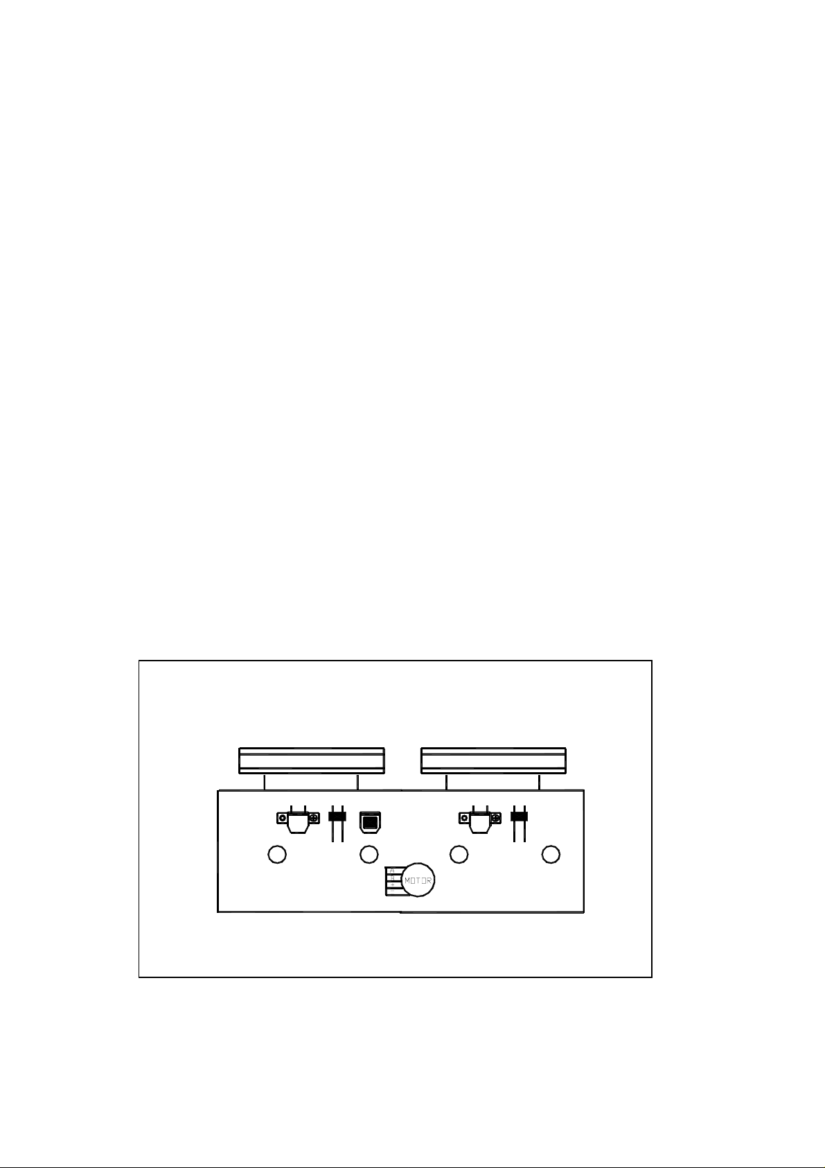
TAPE HEAD AND SPEED ADJUSTMENT DIAGRAM
CASS DECK
A
L. SW
E HEAD
A
L. SW
P/R HEAD
A DECK
P HEAD
B DECK

Tape recorder section
page 3
Measurement Standard Adjusting]
conditions Values positions
Confirmation Test tape 1 Playback the test tape TCC-182A (8KHz) Maximum Adjust the head
of head angle :TA-182A(8KHz) 2 With the recording & playback mechanism, output azimuth screw
Measurement output adjust the head azimuth screw so that the only when the
terminal left and right output levers become head has been
:Speaker terminal maximum, After adjustment, lock the head changed
Sperker R azimuth at least by half turn.
(Load resistance:4Ω)
:Headphone terminal
Confirmation Test tape Adjust VR301 so that the frequrncy counter Tape speed VR301
of tape speed :TCC-112(3000Hz) reading becomes 3,010Hz +/-15Hz when of deck
playing back the test tape TCC-112 (3000Hz) with :3,010Hz
Measurement output playback and recording mechanism after +/-15Hz
terninal ending forward winding if the taoe.
:Headphone terminal
Measrrnment methedItems
Reference Values for Confirmation Items
ITEMS Measrrnment methed
Wow & flutter Test tape When the test tape TCC-112 (3000Hz) has been 0.25% or
Measurement Standard Adjusting]
conditions Values positions
:TCC-112(3000Hz) played back with the recording and playback less
mecganism at the beginning of forward (WRMS)
Measurement outut winding, the frequency counter reading of
terminal wow & flutter should be 0.25% or less
:Headphone terminal (WRMS).
Electrical Performance
ITEMS Measrrnment methed
Adjustment of ˙Mode:Forward or 1 With the recording and playback
recording bias reverse mode mechanism, load thd test tapes
current ˙ Recording mode TDK-60 , and set the mechanism to the recording 4.5μA
(Reference ˙ Test tape and pausing condition in advance . +/-0.5μA
Value) TDK-60
Measurement Standard Adjusting]
conditions Values positions
Measurement output 2 After connecting 100Ωin series to the
termial recorder head, measure the bias current
:Both recording and with a valve voltmeter at both of the
headphone terminals terminals

Adjustment of Reference frequency 1 with the recording and playback Output
n
recording and :1KHz and 8KHz mechanism, load the test tapes (TDK-60) deviation
playback (REF.:-20dB) and set the mechanism to the between
frequency Test tape recording and pausing condition in 1KHz and
characteristics TDK-60 advance 8KHz
Measurement input 2 While repetitively inputting the reference :-1dB +/-2dB
terminal frequency signal of 1KHz and 10KHz from
:OSC IN OSC IN, record and playback the tape.
Reference Values for Electrical Function Confirmation Items
page 4
Items Measrrnment methed
Recording Forward or reverse 1 While changing over to and form BIAS 1 60KHz
bias ˙Test tape and 2, confirm that the frequency is +/-1KHz
frequency TDK-60 changed
Measurement Standard Adjusting]
conditions Values positions
˙Measurement 2 With the recording and playback
terminal : BIAS TP o
P.C. board (TDK-60 ) , and set the
mechanism, load the test tape.
mechanism to the recording and pausing
condition in advance.
3 Confirm that the BIAS TP frequency on the
P.C. board is 60KHz +/-1KHz
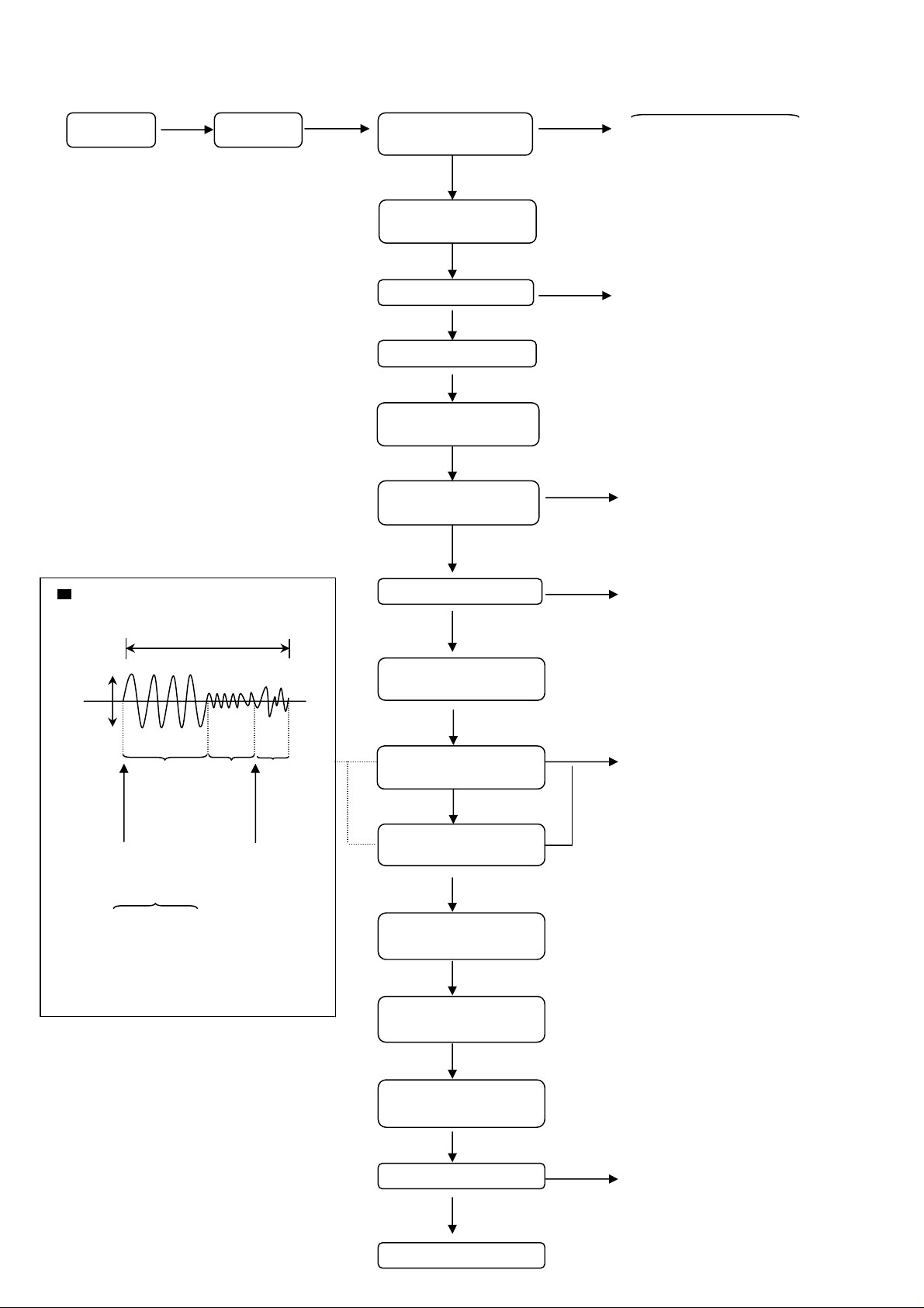
Flow of functional operation until TOC read
(
)
g
Power ON Power Key
Slider turns REST
SW ON.
Automatic tuning
of TE offset
page 5
Check Point
Check that the voltage at the pin
100 of IC501 is OV (a moument)?
Laser ON
Check that the voltage at the
pin1 of IC503 + side is + 5V?
Detection of disc
Automatic tuning of
Focus offset
Automatic measurement
of
Confirm that the Focus error
s-cuve signal at the pin16 of
IC503 is approx.2V p-p
Tracking error waveform at TOC reading Confirm that the signal from
pin 15 of
IC901(TO)
Approx
1.8V
VREF
Approx 3sec
Disc is rotated
Focus servo ON
Tracking servo ON
pin55 IC501 is 0V as a
accelerated pulse during
approx.400ms
Tracking
servo
off status
Disc status
to rotate
Automatic measurement
of TO amplitude and
automatic tuning of
TO balance
Tracking
servo
on status
Disc to be
braked to
stop
TOC reading
finishes
500mV/div
2mS/div Fig.1
Automatic measurement
of
Automatic tuning of
Trackin
error balance
Automatic tuning of
Focus error balance
Automatic tuning of
Focus error gain
Automatic tuning of
Tracking error gain
TOC reading
Confirm the waveform of
the Tracking error signal
at the pin49 of IC501 (R521)
(See fig-1)
Confirm the eys-pattern
at the lead of TP1
Play a disc
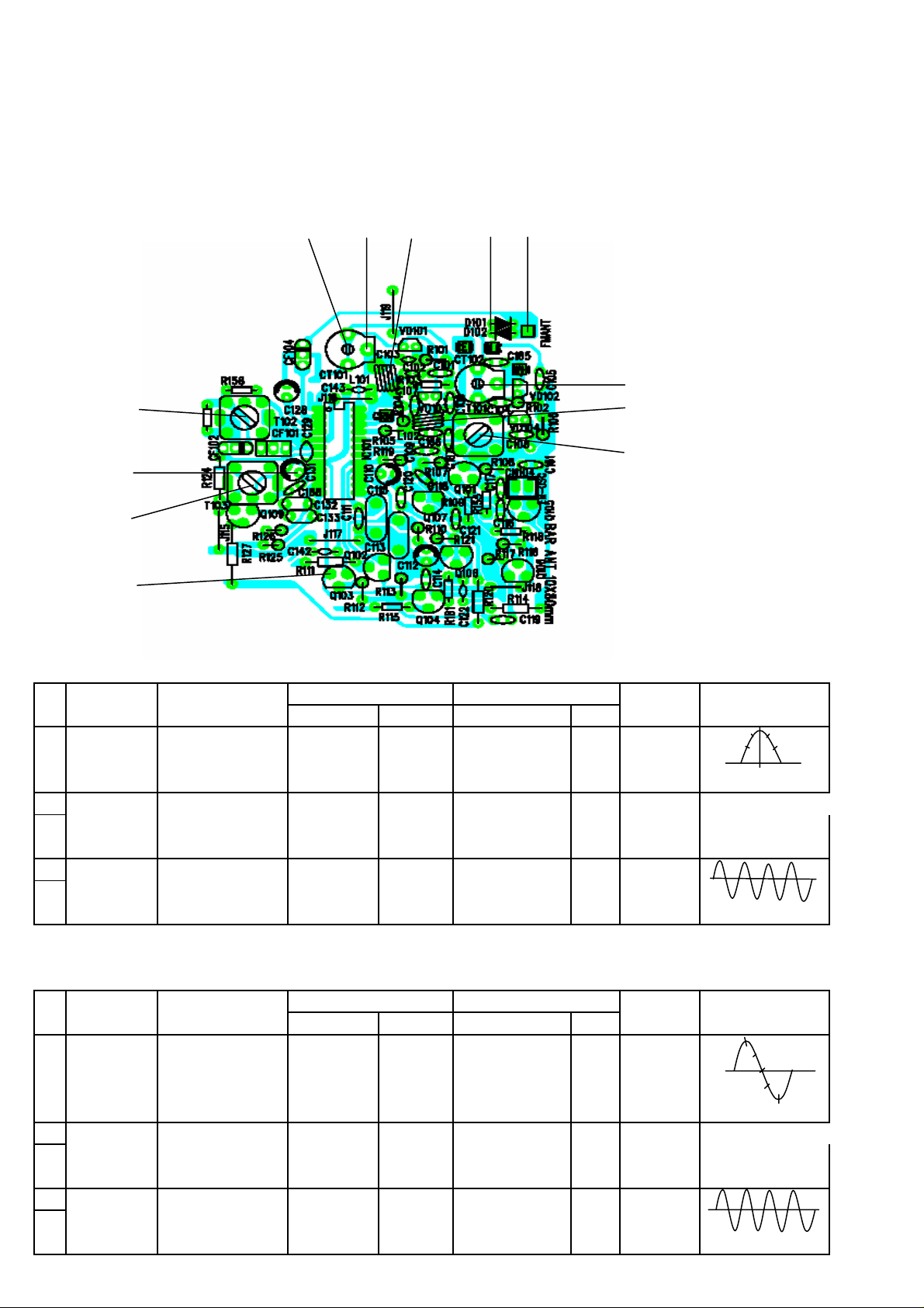
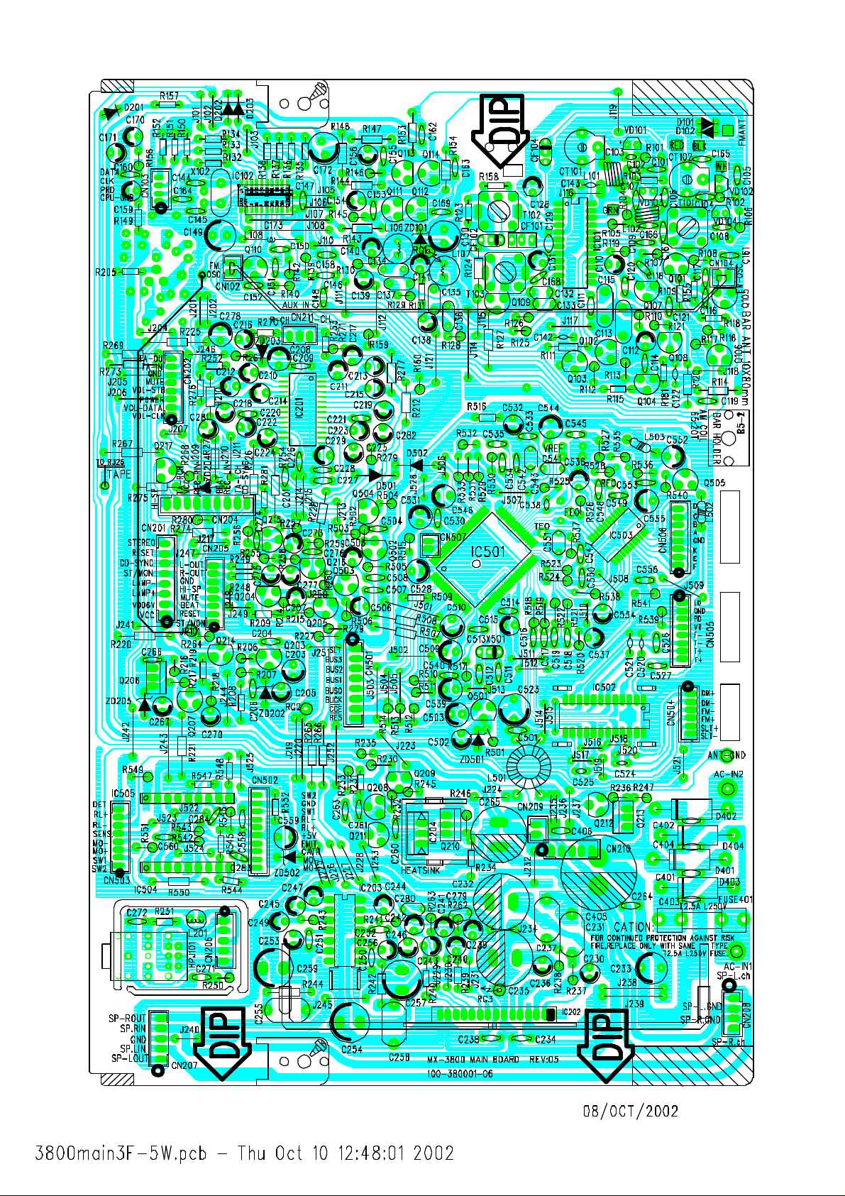
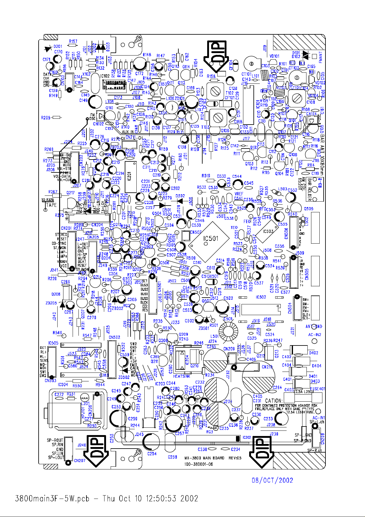
TUNER ADJUSTMENTS
use a plastic screw driver for adjustments.
Adjust the intermediate frequency of AM and FM to the frequency of ceramic filter.
Supply voltage : DC 12.0 V
Speaker impedance : 4 OHMS
Function switch : RADIO
CT101 TP4 L101 TP1 TP2
CT102
T102 L102
T101
TP4
T103
page 6
TP8
a. AM Adjustment BAND SELECT TO : MW
step Adjusting Tuning Input Connection Output Connection Adjustment Oscilloscope
circuit Frequency Measurement input Measurement output parts and VTVM
1 IF 999KHz AM Sweep AM VTVM
(450KHz) 1000 KHz Generior ANT Oscilloscope
TP4(H) T102
TP8(E)
(Non-adjustment)
2 Tuning 522~1620KHz AM Signal AM Digital Voltmeter
3 Coverage 520~1710KHz Generior ANT Oscilloscope
TP4(H) T101 Low END
TP8(E) Confirm 1.8V +/-0.1V
4 603/600 KHz AM Signal AM VTVM TP4(H) AM COIL
5 1404/1400 KHz Generior ANT Oscilloscope
TP8(E) CT102
Maximum
b. FM Adjustment BAND SELECT TO : FM FM Dummy Antenna : 75 ohm unbalance
ste Adjusting Tuning Input Connection Output Connection Adjustment Oscilloscope
circuit Frequency Measurement input Measurement
1 IF FM Sweep TP4(E)
output parts and VTVM
TP4(H)
(10.7 MHz) 98.0 MHz Generator TP4(H) Oscilloscope TP8(E) T103
2 Tuning 87.5 MHz FM Signal FM ANT Digital Voltmeter
3 Coverage 108 MHz Generator TP1 (E) Oscilloscope
TP2(H)
4 90.0 MHz FM Signal FM ANT VTVM
5 Tracking 106.0 MHz Generator TP1 (E) Oscilloscope
TP2(H) Maximum
(Non-adjustment)
TP4(H) L102 Low END
TP8(E) Confirm 1.8 +/-0.1V
TP4(H) L101
TP8(E) CT101
 Loading...