

Page 1

PLASMA MULTIMEDIA MONITOR
AKAI
MODEL NO. : PDP4295ED
SERVICE MANUAL
PDP4249G
PDV42S10
Page 2

CONTENTS
Page
1. IMPORTANT INFORMATION
2. GENERAL INFORMATION
3. SAFETY PRECAUTIONS
4. SPECIFICATION
5. PERIPHERAL EQUIPMENT CONNECTING
6. CIRCUIT DESCRIPTION
. DC POWER SUPPLY
. VIDEO
DISPLAY BOARD
7. CHAPTER BLOCK DIAGRAM
. BLOCK DIAGRAM
. AC FILTER
. EMI BOARD
. DC POWER BOARD
. VIDEO BOARD
. AMPLIFIER BOARD
. TUNER BOARD
. ASSEMBLY DRAWING
8. TROUBLE SHOOTING FLOW CHART
. ASSEMBLY CHART
. SET TEST CHART
. VIDEO DISPLAY CHART
9. CLEANING AND MAINTENANCE HANDY TIPS
1
2
3
4
5
6
7
8
9
10
11
12
13
14
15
16
17
18
19
1
Page 3
IMPORTANT INFORMATION
WARNING
SHOCK !DANGEROUS!
DO NOT OPEN REAR COVER.
WARNING: 1. This is a Class A and Class B product. In a domestic environment this
product may cause radio interference in which case the user may be
required to take adequate measures.
2. TO REDUCE THE RISK OF FIRE AND ELECTRIC SHOCK, DO NOT
EXPOSE THIS PRODUCT TO RAIN OR MOISTURE.
IMPORTANT
This lightning flash with arrowhead symbol, within an equilateral triangle,
is intended to alert the user to the presence of uninsulated
"dangerous voltage" within the product's enclosure that may be of sufficient
magnitude to constitute a risk of electric shock.
!
!
The exclamation point within an equilateral triangle is intended to alert
the user to the presence of important operating and maintenance
(servicing) instructions in the literature accompanying the appliance.
2
Page 4
GENERAL INFORMATION
IMPORTANT:
When the set is switched on , do not shift or move the set around.
Sometimes it may develop an unevenness in colour in some parts
of the screen. This can be eliminated by switching off the set with
the main power button (rear site) and wait for 10 minutes before
switching on again. If the situation remains, call for Service.
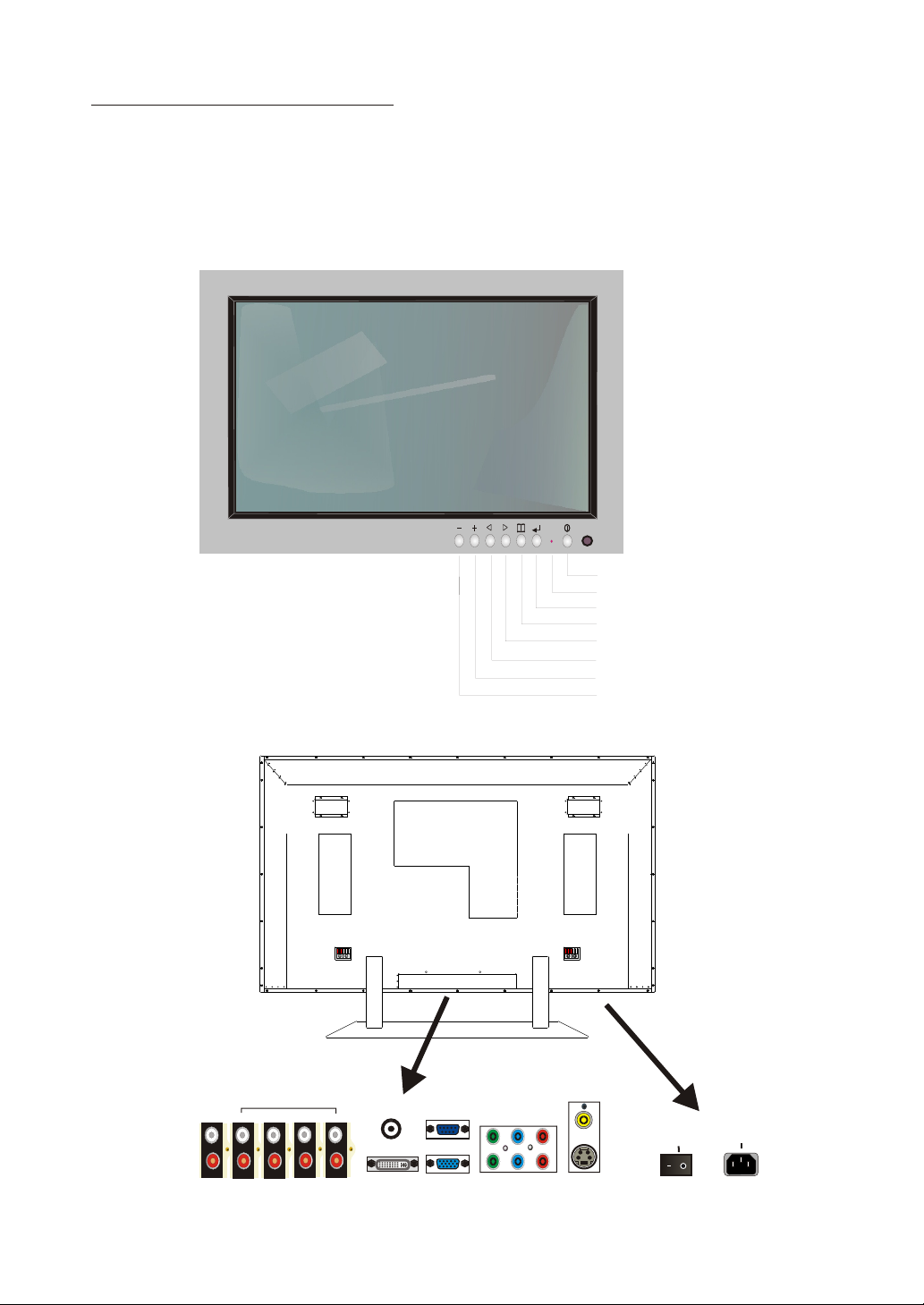
Front View
Rear View
Power
LED
Menu
Enter
Select Up
Select Down
Volume +
Volume -
AUDIO
OUTPUT
COM2
COM1
AUDIO
INPUT
S-V/DVI
SPEAKER L
ANT/CABLE IN
AV/VGA
INPUT
SPEAKER R
RS-232
INPUT
ANALOG VGA
DVI
INPUT
COMPONENT
Y Pb(Cb) Pr(Cr)
AV
S-VIDEO
INPUT
POWER SWITCH
ON OFF
AC 100 240 V
INPUT
3
Page 5

SAFETY PRECAUTIONS
Please read the following direction carefully before using this machine.
. Read each direction carefully, and retain for future reference.
. Please keep the manual well.
. Please follow the information to operate this machine.
. Clean the machine with a slightly damp soft cloth. Do not use spray detergent
and abrasive solvent. It can damage the machine screen coating layer.
. Place the machine on a solid base to avoid dropping and danger.
. For good ventilation of the machine, please do not place the machine on
surfaces such as bed, sofa, or rug.
. Before operating the machine, make sure that the operating voltage of your
machine is identical with that of your local power supply, if there is any
unclear, please contact with sales dealer.
. Use only the accessory power cord designed for this product to prevent shock.
. Do not put anything under the power cord to avoid tramping.
. If using the same power source with other equipments, please make
sure the total current does not over 15A.
. Never attempt to repair a defection of the machine by yourself. Always
consult a skilled machine service personnel.
. When the following situations happen, please contact
qualified engineer.
A. The power cord or the power socket has damages.
B. If any liquid or solid object fall into the machine through the
ventilation holes.
C. Expose the machine to rain or excessive moisture.
D. The function does not follow the user manual.
E. The machine has ever been dropped or the glass has been broken.
F. The function of machine has clear changes.
. The plasma panel has been built using extremely precise and
sophisticated technologies; More than 99.99% of its pixels are
effective. A minute number of pixels are missing or constantly lit.
. Do not display the same picture(pattem)for a long period of time
(Don't exceed 20 min.). This may cause images remain.
.
. No further notice will be provided i f the specification and design
subjects have been changed.
. To release the battery of remote controller after long tim e
replacement (over 1 month) and to avoid making
destruction of remote controller by liquid.
.Whan none operation the product storagr is suggested not
.exced max of 6 months.If it is the exceed the suggested
.storage period,the product should be activated for 24 hrs.
.To ensure the quality of the product.
4
Page 6

(1)input signal :S-Video、composite、Component、Analog RGB、DVI、NTSC RF
(2)video signal:0.7Vp-p
(3)scan frequency: Analog RGB auto-sync H from 30 to 80KHz
V from 60 to 85Hz
DVI auto-sync H from 30 to 80KHz
V from 60 to 85Hz
Component:480i、480P、576i、576P、720P、1080i
Composite:Video sync
S-Video :Y-C separate sync
TV : NTSC 60Hz
(4)up data terminal:RS-232 DB-9 PIN
(5)Power supply:AC100-240 Volts universal
(6)Power consumption:330W (Full White Pattern)
(8)Signal cable:15PIN D-SUB、DVI-D、S-Video、 RCA Jack、Speaker Jack、
AV Shielded Video cable
(9)OSD controls:
Video a section:
<1>Picture: H/V Position、Brightness、Contrast、Sharpness、
Color、Tint、Frequency、Phase、Auto Image
<2>Advanced: Gamma、Color Temperature、Color Management.
<3>Source: Analog RGB、DVI、Component1、Component2、
S-Video、Vi deo、 TV
<4>Function: Scaling、Zoom、White Pattern、Close Caption、
[PIP]Source、 [PIP]Size、[PIP]H/V-Position
<5>Utility: Language、Video Standard、DPMS、
[OSD]H/V-Position、[OSD]Time Out、
Picture Scrolling、Load Factory
<6>TV: Tuner Select、Channel、MTS、Channel Scan、V-chip
Sound a section:
Volume、Treble、Bass、4 steps BBE Selects、SRS virtual Surround、
MTS STEREO Decoder
SPECIFICATION
5
Page 7
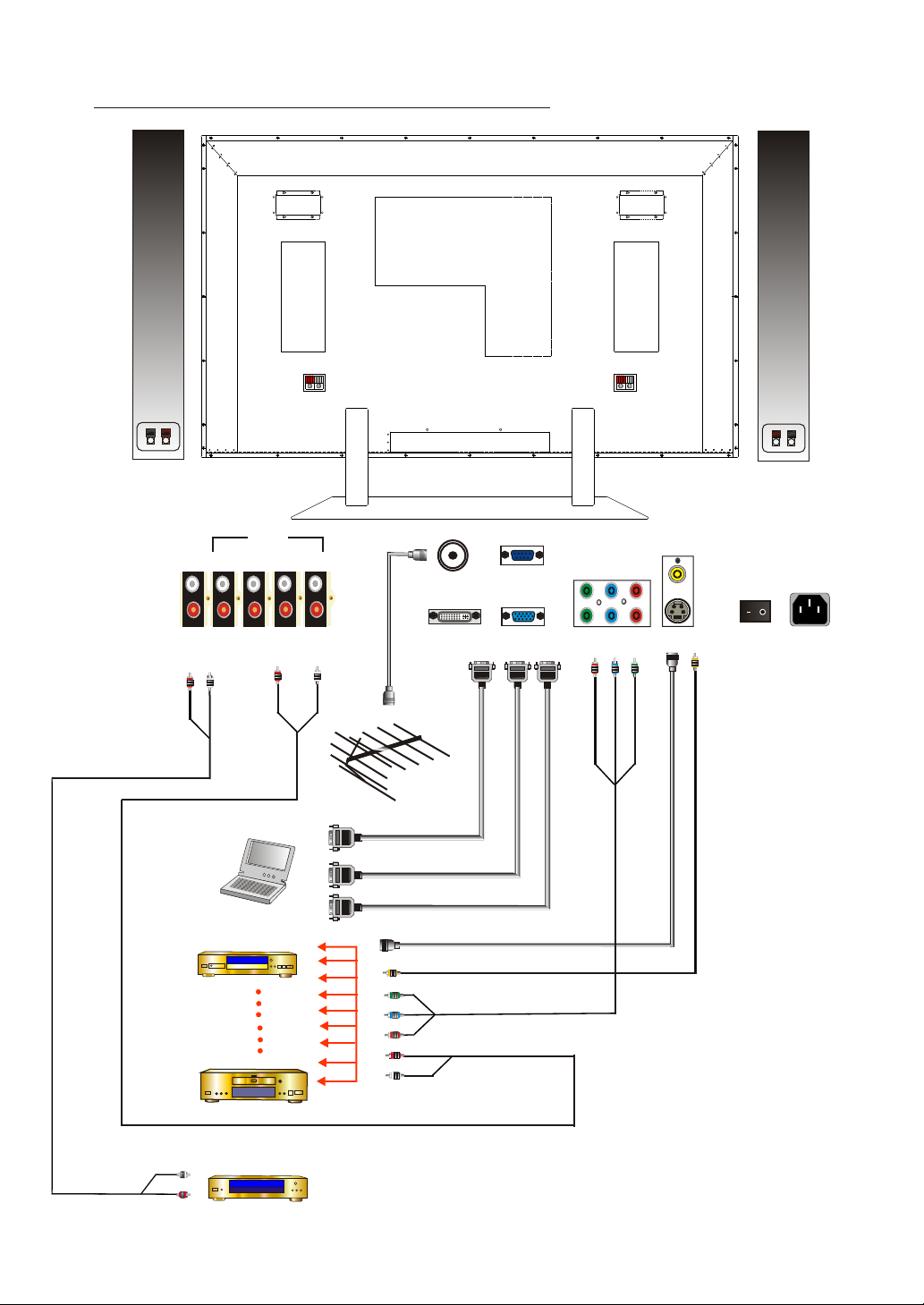
PERIPHERAL EQUIPMENT CONNECTING
AUDIO
OUTPUT
PC
DVD
VCR
COM2
COM1
AUDIO
INPUT
S-V/DVI
AV/VGA
ANT/CABLE IN
INPUT
Antenna/Cable
DVI-D Output
RS-232
INPUT
Analog RGB Output
DVD S-Video Output
DVD Video Output
DVD Y Pb(Cb) Pr (Cr) Output
RS-232
DVI
ANALOG
VGA IN
DVD Audio Output
INPUT
COMPONENT
Y Pb(Cb) Pr(Cr)
AV
S-VIDEO
INPUT
POWER SWITCH
ON OFF
AC 90 240 V
INPUT
Audio Input
Amplifier
6
Page 8

CIRCUIT DESCRIPTION
1. DC POWER SUPPLY
This is the DC power supply inside the PDP, in which Cn1 connected
with alternating current (AC) through inductance filter (L1),
rectification bridge (BD1) IC, transformer (T1), D3, D4, to CN2 output
with 5V and 12V direct current. The range of the AC output is from 90V to
264V and frequency is from 50Hz to 60Hz. The largest detrition
rate is 40W
7
Page 9

2. VIDEO DISPLAY BOARD
This is the signal inside the PDP and audio device disposition.
1) It can receive composite signal including R.G.B.H.V. contrast
signal, DVI digital signal, AV color distinction signal and
S-Video.....etc.
R.G.B.H.V. & Y Pb Pr :The signal is input from (15 PIN) J1 & J1
to U6 to perform contrast signal ,then
transform to digital signal and enter to U29 ,
the signal is passer to U33 for the output of
visual signal.
DVI : Digital signal is input from P1 the managed by U6 and passed
to U29 ,the signal is passed to U33 for the output of visual
signal output.
AV & TV : AV& TV signal enters from J12 & JP18 to U46 to
perform signal, then transform to U47 to decode perform
signal , then transform to U49 to deinterlace perform signal
and enter to U29 , the signal passed to U33 for the output
of visual signal.
S-Video : S-Video signal input from J12 to U47 to decode perform
signal ,then transform to U49 to deinterlace preform
signal and enter to U29 , the signal passed to U33 for the
output of visual signal.
to U5 for visual production and after deposition, it will pass
to U7 for signal compensation and to U9 for visual signal
deposition output.
2) Audio is input from J3, J8 and from U62 to perform
pre-production. Then, the audio signal is passed to U61 SRS process
for the signal output by J4 and J9.
3) When audio signal the J4 passed to Amplify for the final output.
8
Page 10

CHAPTER BLOCK DIAGRAM
1. BLOCK DIAGRAM
PANEL
AMPLIFIER
BOARD
DC
POWER
EMI BOARD
TUNER
BOARD
VIDEO
BOARD
AC IN
9
Page 11

2. AC FILTER
1. AC INPUT TO C1
2. C2 TO EMI BOARD J1
10
Page 12

3. EMI BOARD
1. AC FILTER C2 TO J1
2. J2 TO PANEL & DC POWER CN1
11
Page 13

4. DC POWER BOARD
CN1
NC 2
1. EMI FILTER J2 TO CN1
2: CN2 TO MONITOR BOARD
12
Page 14

5. VIDEO DISPLAY BOARD
Jp18
Jp1
J25
Jp11
J5
1.J17 TO PANEL
2.JP17, JP3 TO TUNER BOARD
3.J25 TO DC POWER
4.JP11 TO KEYPAD
5.J4 TO AMPLIFIER BOARD
6.J5 TO RS232 CONNECTOR
J17
J4
Jp17
Jp3
13
Page 15

6. AMPLIFIER BOARD
1. VIDEO BOARD J4 TO JP1
2. DC POWER BOARD CN2 TO JP2
3. JP3 TO RIGHT SPEAKER JACK
4. JP4 TO LEFT SPEAKER JACK
14
Page 16

7. TUNER BOARD
Jp1
J1
CABLE IN
1. VIDEO BOARD JP17 TO JP1
2. VIDEO BOARD JP3 TO J1
3. CABLE TO CABLE INPUT
15
Page 17

8. ASSEMBLY DRAWING
16
Page 18

TROUBLE SHOOTING FLOW CHART
1. ASSEMBLY CHART
NO
YES
NO
NO
YES
YES
17
Page 19

2. SET TEST CHART
CHECK
1. AC INPUT
2. DC POWER
3. VIDEO BOARD
CHECK
1. SPEAKER
2. VIDEO BOARD
3. AUDIO CIRCUIT
FIX
WHITE PATTEN
TEST
NO
NO
NO
NO
VIDEO DISPLAY
I/P
YES
AUDIO VOLUME
I/P
YES
PANEL DISPLAY
18
YES
END
Page 20

3. VIDEO DISPLAY CHART
CHECK
1.
CABLE
2.
SIGNAL
3. U6
CHECK
1. CABLE
2. SIGNAL
3. U46, U47, U49
CHECK
1. CABLE
2. SIGNAL
3. U7, U9, U61, U62
NO
NO
NO
NO
RGB I/O
DVI I/O
YES
AV I/O
YES
AUDIO I/O
19
YES
END
Page 21

TROUBLE SHOOTING FLOW CHART
In the even of problems with the display, check the following explanations before
contacting your dealer for servicing.
Problem
Power does not turn ON.
Remote control does not function properly.
The display makes a snapping sound.
There are spots on the screen.
Action
Check whether the power plug is securely inserted
into the receptacle.
Check for incorrect battery orientation.
Check for dead batteries.
Check for distance from the display.
Check whether you are pointing the remote control
transmitter properly at the display's receiver.
Check for any obstacle between the remote control
and display.
This sound is produced when the cabinet expands
or contract due to variations in temperature.
This sound does not indicated that the display
has a problem.
Check whether your AV equipment is affected by
interference from automobiles, trains,
high-voltage transmission lines, neon signs or
other potential sources of interference.
Degraded colour/tints.
Improper screen position/size
If "Out of range" appears, the display is
receiving a signal whose picture or signal
cannot be reproduced by the display.
The screen turns to black and white.
Check whether all picture adjustment have been
properly made.
Check whether screen position and size have been
properly adjusted.
Input proper signals.
Make sure that the vertical frequency of the input
signal is 85 Hz or less for SVGA, 75 Hz or less for
XVGA / SXGA, 60 Hz or less for UXGA.
Input proper signals.
Make sure that the vertical frequency of the input
signal is 85 Hz or less for SVGA, 75 Hz or less for
XVGA / SXGA, 60 Hz or less for UXGA.
20
 Loading...