

Page 1
Models:
LTA-15E302
LTA-20E302
LTA-20E303
www.akai.ru
Page 2

Akai LTA-15E302, LTA-20E302, LTA-20E303
LCD-TV Service Manual
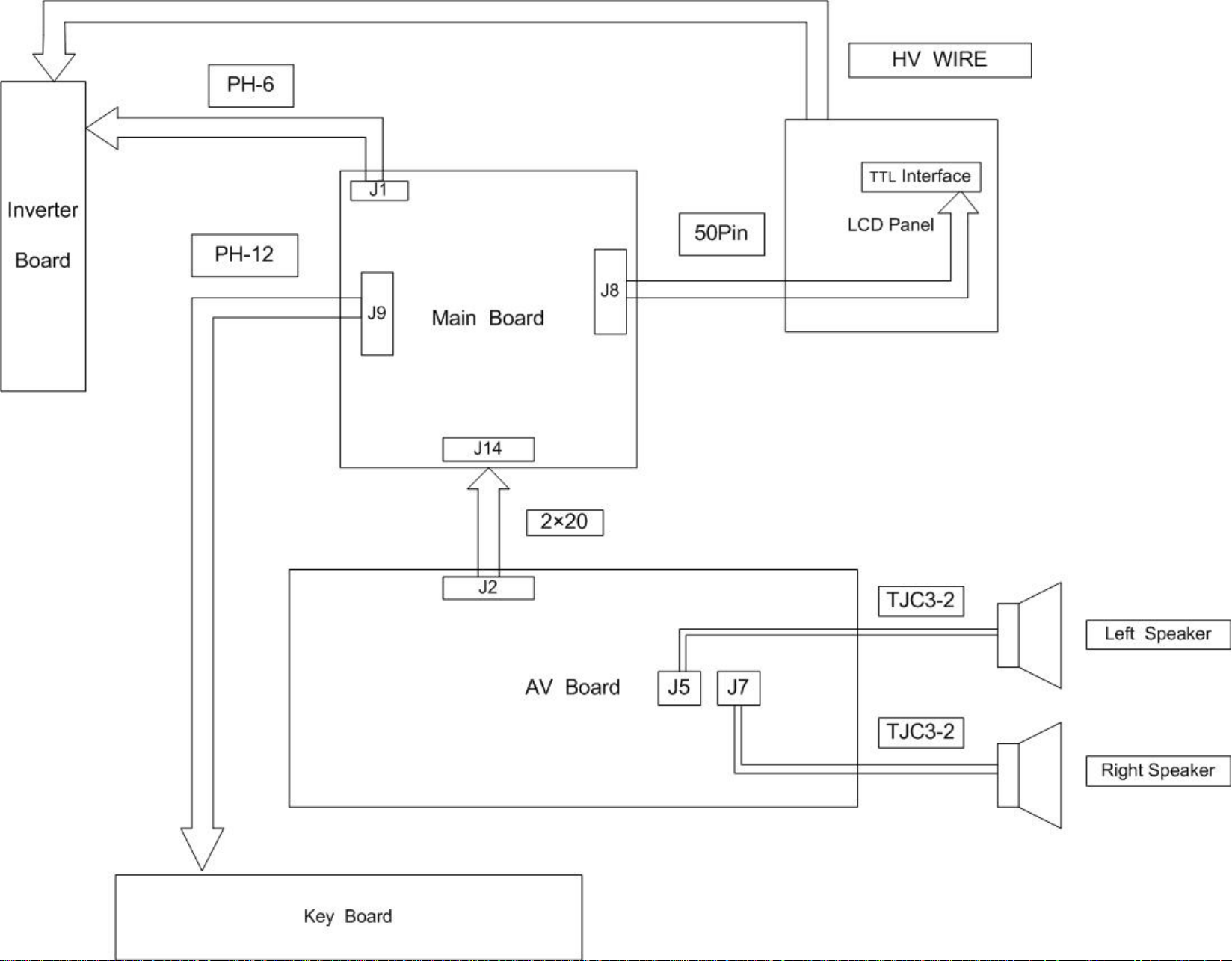
1. The System Block Diagram&the Block’s Function Description
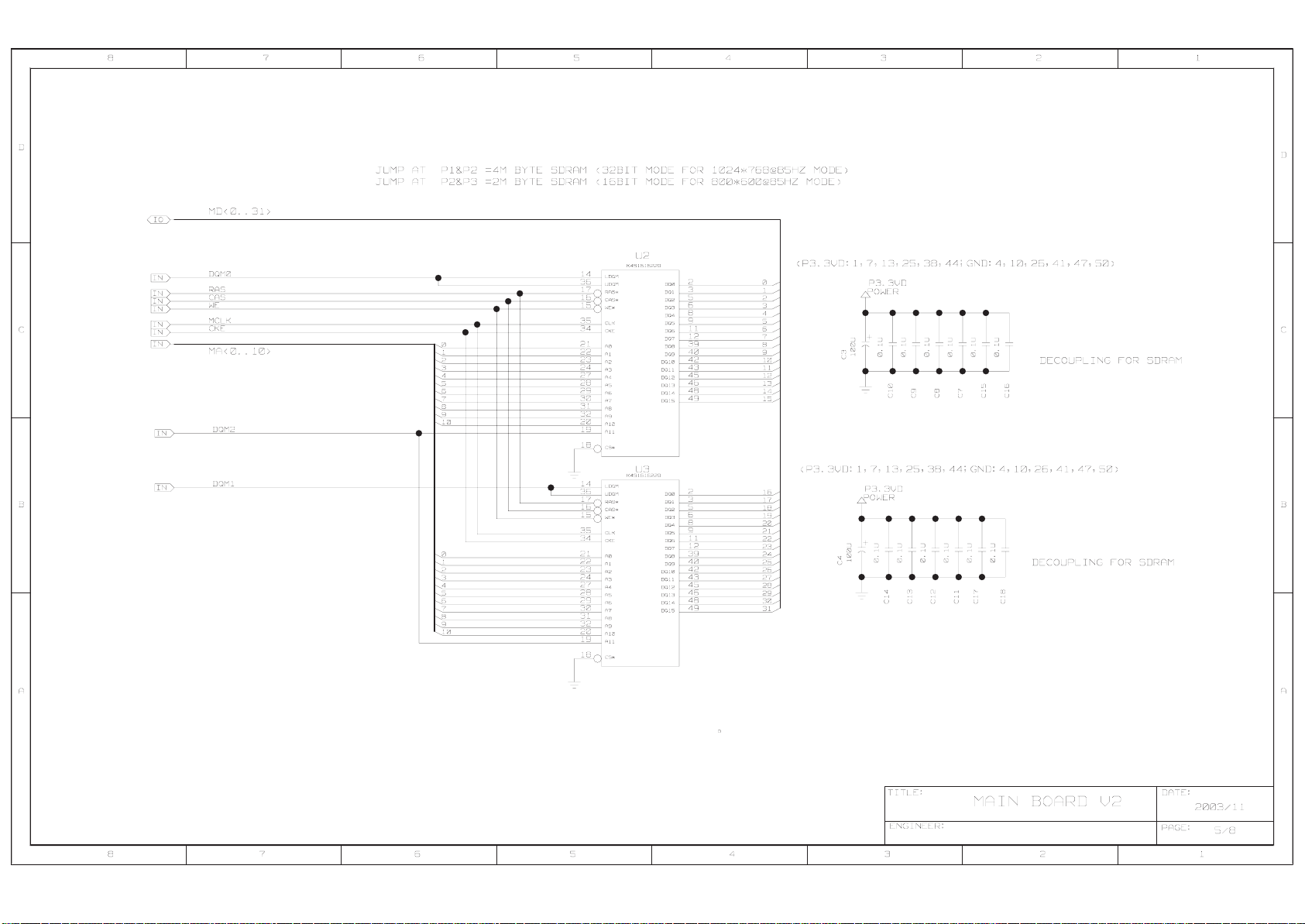
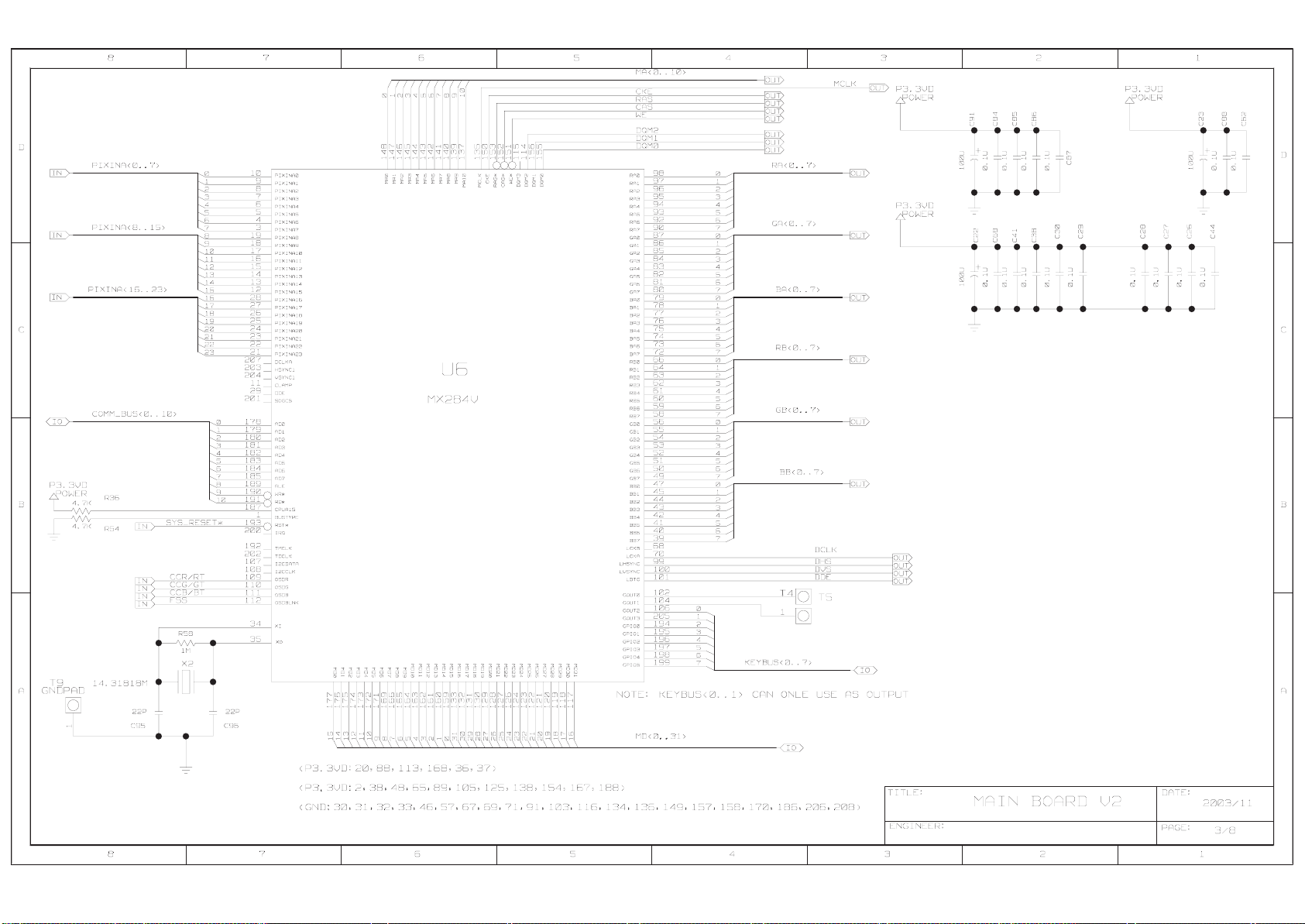
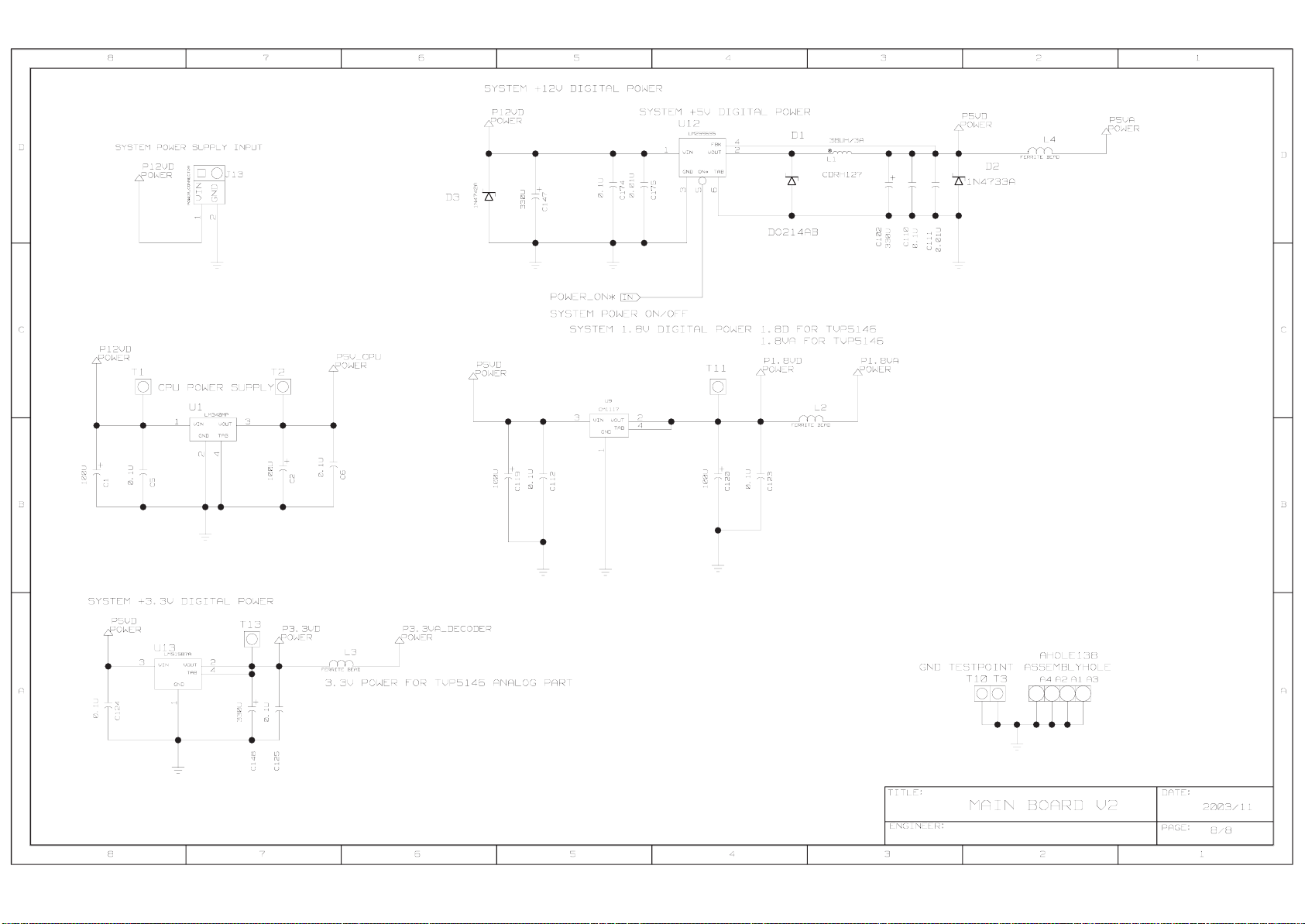
2. Schematic Circuit Diagram
3. Interconnection Diagram
4. Critical Connpoents List
5. IC Date Sheet&IC Description
6. Service Tools and Epuipment
Page 3
Page 4

Page 5
Page 6
Page 7
Page 8

Page 9

Page 10

Page 11

Page 12

Page 13

Page 14

Page 15

Page 16

Page 17

Page 18

The SCART Interface
The Scart (Syndicat des Constructeurs d'Appareils Radiore cepteurs et Te le viseurs) connector
is used for combined audio and video connections.
The connector is also known as Pertitel connector or Euroconnector.
Male front view
The Scart is a twenty one pin connector plug developed by the European community and
found on the back of most European televisions and video players. It is used in most of the
consumer video equipments like VCRs, TVs and DVD players to hand the audio and video
connections all using some connector. SCART connector supports stereo audio, composite
video, S-video, RGB and some control signals. SCART connector can use to carry many
signal formats, but it can't carry all of them at the same time. Note that not all SCART
connections in all equipment are equivalent, connectors on other equipments might support
more signal format than others. Composite video and audio are practically always supported,
but there are lots of equipments that do not support RGB or S-video. For example some TVs
support RGB on one SCART and S-video on other SCART (in addition to standard composite
video format). The supported RGB signal format is RGBS (R, G, B and composite sync).
Arrangement 1 was the original and allows for composite video input/output, RGB inputs and
stereo audio.
Arrangement 2 was added to take S-Video (S-VHS and Hi-8) inputs. This made pin 15
chrominance and pin 20 luminance.
A recent addition is a ternary level on pin 8 to signal a VCR in wide-screen mode.
Most new TV sets have 2 SCART sockets on their rear. One is usually to arrangement 1 and
the other to arrangement 2, but with pin 20 switchable from composite to S-Video luminance.
The first can switch from a composite input to RGB input. The second can switch from a
composite input to an S-Video input, pin 20 being either composite in or luminance in. Usually
the second socket outputs a selectable composite signal on pin 19. That is selectable from
off-air, SCART 1, and if they exist front mounted input sockets for a camcorder.
PDF created with FinePrint pdfFactory trial version http://www.fineprint.com
Page 19

SCART arrangement 1
Pin Signal Signal level Impedance
1 Audio output B (Right) 0.5V rms <1kohm
2 Audio input B (Right) 0.5V rms >10kohm
3 Audio output A (Left) 0.5V rms <1kohm
4 Ground (Audio)
5 Ground (blue)
6 Audio input A (Left) 0.5V rms >10kohm
7 Blue input/output 0.7V 75ohms
Function select (AV control)
8
9 Ground (green)
10 Comms data 2
11 Green input/output 0.7V 75ohms
12 Comms data 1
13 Ground (red)
14 Ground (blanking)
15 Red input/output 0.7V 75ohms
Fast Blanking
16
17 Ground (video output)
18 Ground (video Input )
19 Video output (composite) 1V including sync 75ohms
High (9.5-12V) - AV mode
Mid (5-8V) - Wide-screen
Low (0-2V) - TV mode
High (1-3V) - RGB
Low (0-0.4V) - Composite
>10kohm
75ohms
20 Video input (composite) 1V including sync 75ohms
21 Common ground (shield)
PDF created with FinePrint pdfFactory trial version http://www.fineprint.com
Page 20

SCART arrangement 2
Pin Signal Signal level Impedance
1 Audio output B (Right) 0.5V rms <1kohm
2 Audio input B (Right) 0.5V rms >10kohm
3 Audio output A (Left) 0.5V rms <1kohm
4 Ground (Audio)
5 Ground
6 Audio input A (Left) 0.5V rms >10kohm
7
Function select (AV control)
8
9 Ground
10 Comms data 2
11
12 Comms data 1
13 Ground
14 Ground (blanking)
15 Chrominance input 0.3V 75ohms
16
17 Ground (Luminance Output)
18 Ground (Luminance input)
19 Luminance Output 1V including sync 75ohms
20 Luminance input 1V including sync 75ohms
High (9.5-12V) - AV mode
Mid (5-8V) - Wide-screen
Low (0-2V) - TV mode
>10kohm
21 Common ground (shield)
PDF created with FinePrint pdfFactory trial version http://www.fineprint.com
Page 21

RGB Connection
Output Connector Input Connector
Pin Signal Pin Signal
1
Audio output B (Right)
2 Audio input B (Right)
3
Audio output A (Left)
4
Ground (Audio)
7
Blue Output
5
Ground (blue)
11
Green Output
9 Ground (Green) 9 Ground (Green)
15 Red Output 15 Red Input
13 Ground (Red) 13 Ground (Red)
16 RGB Status out 16 RGB Status in
14 Ground (RGB Status) 14 Ground (RGB Status)
19 Sync out 20 Sync in
17 Ground 18 Ground
21 Shield 21 Shield
6 Audio input A (Left)
4 Ground (Audio)
7 Blue input
5 Ground (blue)
11 Green Input
Composite Video Connection
Output Connector Input Connector
Pin Signal Pin Signal
1
Audio output B (Right)
2 Audio input B (Right)
3
Audio output A (Left)
4
Ground (Audio)
8 Video status out 8 Video status in
19 Composite video out 20 Composite video in
17 Ground 18 Ground
21 Shield 21 Shield
6 Audio input A (Left)
4 Ground (Audio)
PDF created with FinePrint pdfFactory trial version http://www.fineprint.com
Page 22

Critical Components List
Components Designator Function
MX88L284 U8 SCALER
SM5964C40Q U4 MCU
TVP5146PFP U15 Video Decoder
TDA9874 U19 Nicam&A2
TDA9860 U12 Audio Processor
TDA8944 U14 Audio Amplifier
IS42S16100A1-7T U5,U9 SDRAM
LM2596 U1 Switch Power
LM1084 U6 LDO
SN74CBT3253PWR U21 Switch
SN74CBT3253 U20 Switch
DS90C383 U2 LVDS
FDS4953
BM1117-1.8V U18
U3、U7
MOS
dropout voltage regulators
Page 23

Service Tools and Equipment
Application Name
General
Confirm
Special
DVD testing disk
General tools(screwdriver ect.)
AV Cable
S-Video Cable
Scart Cable
SVCD testing disk
DVD player
TV set
Signal Generator
Oscillograph
Probe
Antistatic Electric Iron Antistatic
Antistatic Wrist Strap
Atraumatic Sponge Underlay
 Loading...