

Page 1
IB-4ADT adat Digital Interface Board for Z4/Z8/MPC4000
Thank you for your purchase of the IB-4ADT adatTM Digital Interface Board for the Z4/Z8 samplers/MPC4000
Music Production Center.
This interface board is made exclusively for the Z4/Z8
Samplers/MPC4000 Music Production Center to handle
the 2-channel digital input and 8-channel output signal
with other digital equipment in adat format.
Refer to the Z4/Z8, MPC4000 Operator’s Manual for the
details of operation.
Note: The IB-48P 8-Individual Output Board cannot be
installed at the same time (Z4/Z8 only).
✽ Installing the IB-4ADT
The self-installation may cause the malfunction and/or
damage to your equipment. Refer installing of this board
to your AKAI professional dealer where you purchased or
AKAI professional service center.
<To Service Technicians>
Install the IB-4ADT to the Z4/Z8, MPC4000 following the
procedures below. Be sure to unplug its power cord before installing the board.
! Components
IB-4ADT adat Interface Board ................................. 1
Mounting Post (Short, MPC4000) ........................... 1
Mounting Post (Middle, Z4/Z8) ................................ 1
Mounting Post (Long, MPC4000)............................ 2
8-pin Connecting Cable .......................................... 1
Fixing Screw (black, Z4/Z8) .................................... 1
Fixing Screw (gold, MPC4000) ............................... 2
Instruction Sheet ..................................................... 1
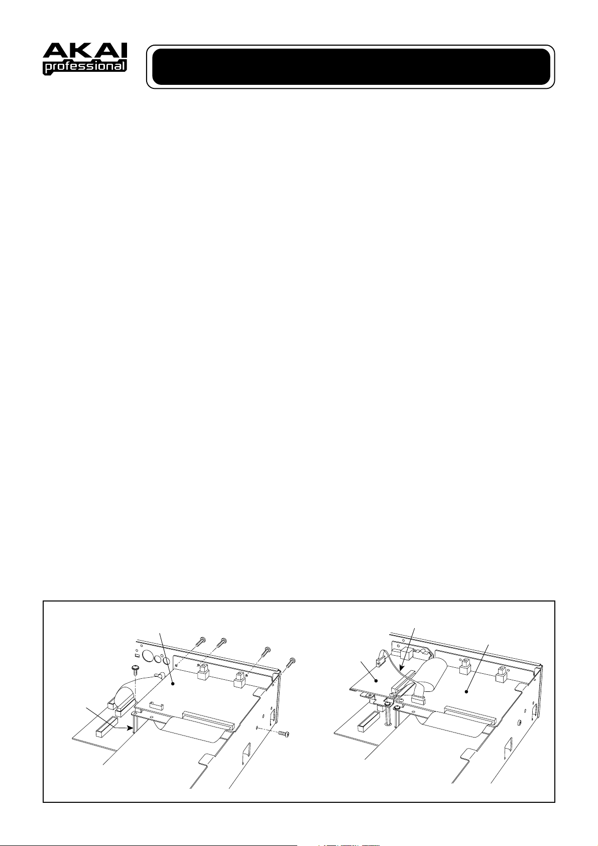
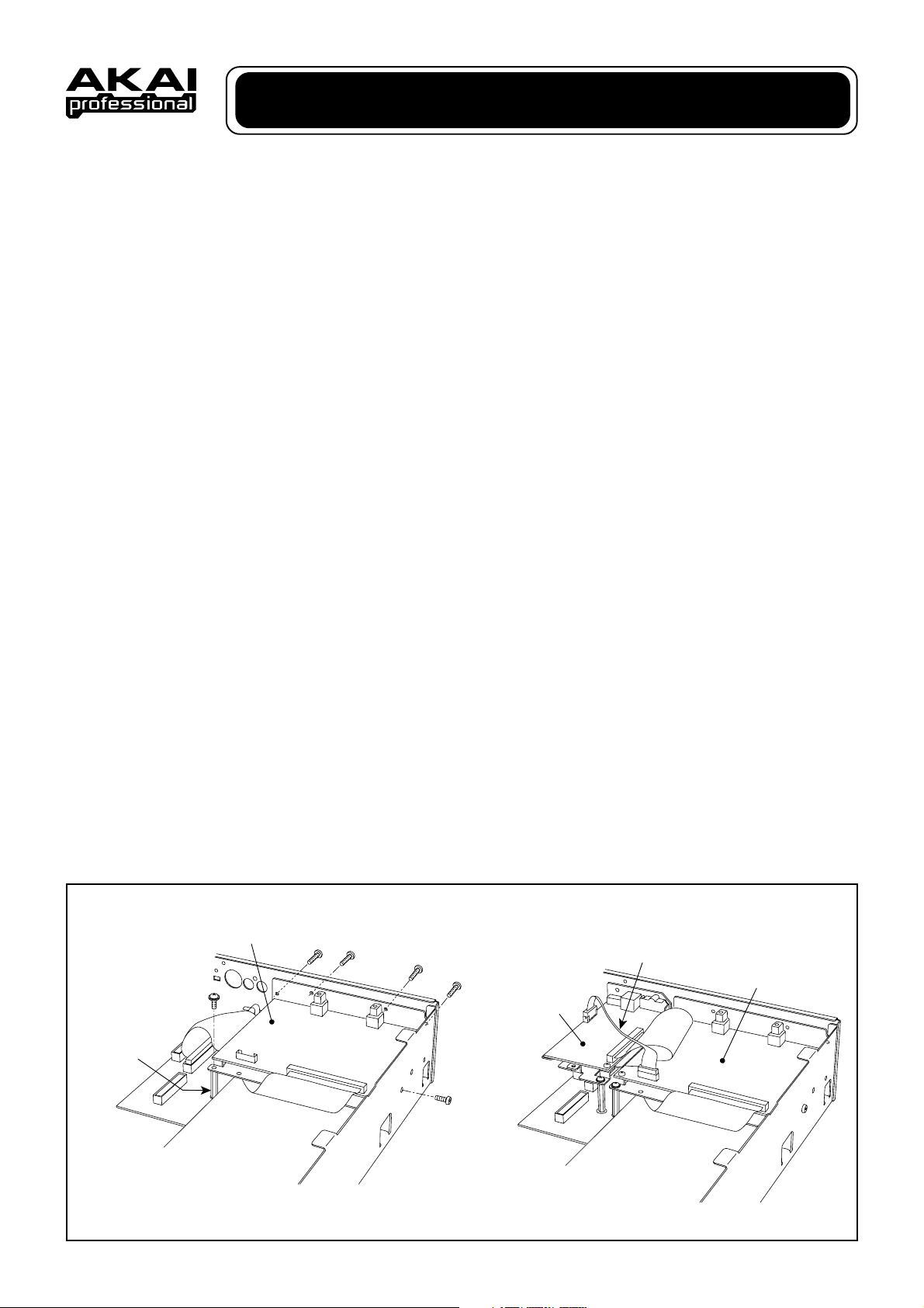
! Installation - Z4/Z8
1. Remove the fixing screws of the Z4/Z8 Top Cover on
its sides (2pcs. on each side) and its back center (1pc.)
and remove the Top Cover. If the Handles are used,
remove their fixing screws and then Handles.
2. Remove the fixing screws (4pcs.) for the Mask Plate
on the Rear Panel and remove the Mask Plate. Save
the screws for later use. The Mask Plate is not used.
3. Referring to the illustration, remove the fixing screw
(1pc.) on the I/O board and install the Mounting Post
(M) in its place. Save the screw for later use.
4. On the Z8 or Z4 with IB-4D SP-DIF Digital Interface
Board installed, remove its fixing screws and take the
board out. Leave the connection cable connected.
5. Connect the cable from the IB-4ADT board to the connector (P4) on the I/O board.
6. Set the IB-4ADT on the Rear Panel and Mounting Post
(M) and fix it securely with the screws removed in earlier steps and the fixing screw (black) included.
7. Replace the IB-4D board back and connect the 8-pin
Connecting Cable included between the IB-4D and IB4ADT boards.
8. Replace and fix the Top Cover (and Handles) to complete the installation.
✽ Be sure to fix the screws and connectors securely to
avoid malfunctioning.
Z4/Z8
Mounting Post(M)
P4
IB-4ADT
IB-4D
Digital I/O Board
8pin Connection Cable
IB-4ADT
Page 2
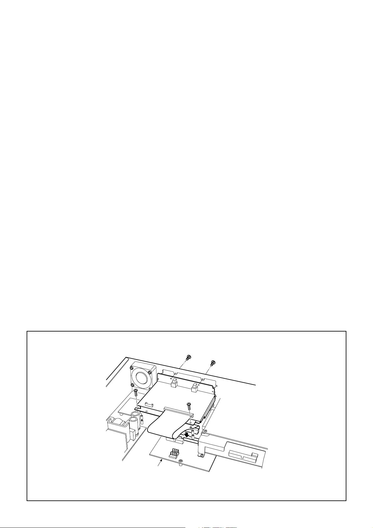
! Installation – MPC4000
1. Remove the fixing screws of the MPC4000 Side Panels (4pcs. on each side) and remove Side Panels. Next,
remove the screws (5pcs. on each side) hidden by the
Side Panels and then remove the center screws (2pcs.)
located underneath the Armrest and the topmost of
Rear Panel. The Top Panel Block can be swing-opened
by lifting the Armrest from the front. Save the removed
screws.
2. Remove the fixing screws (4pcs.) for the Mask Plate
(upper slot) on the Rear Panel and remove the Mask
Plate. Save the screws for later use. The Mask Plate
is not used.
3. Referring to the illustration, remove the fixing screw
(1pc.) on the I/O board and install the Mounting Post
(S) in its place. Then extend the 2 Mounting Posts with
the 2 Mounting Posts (L) included.
4. Set the IB-48P on the Rear Panel and Mounting Posts
and fix it securely with the screws removed in earlier
step and the Fixing Screws (gold, 2pcs.) included.
5. Connect the cable from the IB-4ADT board to the connector (P4) on the I/O board.
6. Replace and fix the Top Panel Block and Side Panels
in the opposite order to which they were removed.
Note 2: On the MPC4000 with IB-4D SP-DIF Digital Interface Board installed, Connect the 8-pin Connecting
Cable included between the IB-4D (P2) and IB-4ADT (P1)
boards.
✽ Be sure to fix the screws and connectors securely to
avoid malfunctioning.
Note 1: When the IB-48P 8-Individual Output board is
installed at the lower slot, remove the fixing screws (2pcs.)
of the Mounting Posts for the IB-48P and replace them
with the 2 Mounting Posts (L) included and mount the IB4ADT on them.
MPC4000
IB-4ADT
PC IO
P2
P4
Page 3
KIT-MFC MFC42 Mounting Kit for MPC2000/MPC2000XL
IB-4ADT adat Digital Interface Board for Z4/Z8/MPC4000
Nous vous remercions d’avoir acheté cette carte interface numérique IB-4ADT adat™ pour les samplers Z4/
Z8/Centre de production de musique MPC4000.
Cette carte interface est conçue exclusivement pour les
samplers Z4/Z8/Centre de production de musique
MPC4000 pour gérer les signaux d’entrée numérique 2
canaux et de sortie 8 canaux avec d’autres équipements
numériques en format adat.
Pour obtenir des détails sur l’utilisation, référez-vous aux
Manuels d’utilisation des Z4/Z8 et MPC4000.
Remarque: La carte à 8 sorties individuelles IB-48P ne
peut pas être installée en même temps.(Z4/Z8
uniquement)
✽ Installer le IB-4ADT
Installer l’appareil soi-même risque de provoquer un
dysfonctionnement de l’appareil ou d’entraîner des
dommages. Laissez le soin d’installer cette carte à
votre revendeur AKAI professional ou faites appel à
un service après-vente AKAI professional.
<A I’attention des techniciens d’assistance>
Installez la carte IB-4ADT sur le Z4/Z8, MPC4000 en
suivant la procédure ci-dessous. Veillez à débrancher le
cordon d’alimentation avant de procéder à l’installation
de la carte.
! Composants
Carte d’interface adat IB-4ADT .............................. 1
Montant (Court, MPC4000) ..................................... 1
Montant (Milieu, Z4/Z8) ........................................... 1
Montant (Long, MPC4000)...................................... 2
Câble de connexion à 8 broches ............................ 1
Vis de fixation (noir, Z4/Z8) .................................... 1
Vis de fixation (or, MPC4000) ................................ 2
Fiche d’instructions ................................................. 1
! Installation - Z4/Z8
1. Retirez les vis de fixation sur les côtés du couvercle
supérieur du Z4/Z8 (2 de chaque côté) et au centre de
la face arrière (1) puis déposez le couvercle supérieur.
Si les poignées sont utilisées, ôtez les vis de fixation
puis retirez-les.
2. Retirez les vis de fixation (4) de la plaque de masquage
située sur la face arrière puis ôtez la plaque de
masquage. Conservez les vis pour plus tard. La plaque
de masquage n’est pas utilisée.
3. En vous reportant à l’illustration, retirez la vis de fixation (1) de la carte E/S et mettez le montant (M) en
place. Conservez la vis pour plus tard.
4. Retirez les vis de fixation du Z8 ou du Z4 en laissant la
carte d’interface numérique SP-DIF IB-4D en place et
ôtez la carte. Laissez le câble de connexion branché.
5. Connectez le câble de la carte IB-4ADT au connecteur
(P4) de la carte E/S.
6. Placez la carte IB-4ADT sur la face arrière et le montant
(M) et fixez la solidement à l’aide des vis
précédemment retirées et en incluant la vis de fixation
(noir).
7. Remettez la carte IB-4D en place et connectez le câble
de connexion à 8 broches inclus entre les cartes IB4D et IB-4ADT.
8. Pour achever le montage, remettez le couvercle
supérieur (et les poignées) en place et fixez-le.
✽ Assurez-vous de bien fixer les vis et les connecteurs
pour éviter un dysfonctionnement.
Z4/Z8
Mounting Post(M)
P4
IB-4ADT
IB-4D
Digital I/O Board
8pin Connection Cable
IB-4ADT
Page 4

! Installation - MPC4000
1. Retirez les vis de fixation des panneaux latéraux du
MPC4000 (4 pièces de chaque côté) et retirez les
panneaux latéraux. Ensuite, retirez les vis (5 pièces
de chaque côté) cachés par les panneaux latéraux puis
retirez les vis centrales (2 pièces) situées en dessous
de l’accoudoir et de la partie supérieure du panneau
arrière. Le bloc du panneau supérieur peut être ouvert
en soulevant l’accoudoir par l’avant. Conservez les vis
retirées.
2. Retirez les vis de fixation (4 pièces) de la plaque de
cache (fente supérieure) sur le panneau arrière et
retirez la plaque de cache. Conservez les vis pour
l’utilisation future. La plaque de cache n’est pas utilisée.
3. En vous référant à l’illustration, retirez la vis de fixation (1 pièce) sur la carte E/S et installez le montant
(S) à la place. Ensuite, allongez les 2 montants à l’aide
des 2 autres montants (L) inclus.
4. Placez la carte IB-48P sur le panneau arrière et les
montants et fixez-le fermement avec les vis retirées
lors de l’étape précédente et avec les vis de fixation
inclues (2 pièces) (dorées).
5. Connectez le câble provenant de la carte IB-4ADT au
connecteur (P4) sur la carte E/S.
6. Remettez en place et fixez le bloc du panneau
supérieur et les panneaux latéraux dans l’ordre inverse
de celui dans lequel ils ont été retirés.
Remarque 1: Lorsque la carte d’extension à 8 sorties
individuelles IB-48P est installée dans la fente inférieure,
retirez les vis de fixation (2 pièces) des montants de la
carte IB-48P et remplacez-les par les 2 montants (L) inclus
puis montez l’IB-4ADT sur ces derniers.
Remarque 2 : Sur le MPC4000 avec la carte d’interface
numérique IB-4D SP-DIF installée, connectez le câble
de connexion à 8-broches fourni entre les cartes IB-4D
(P2) et IB-4ADT (P1).
✽ Assurez-vous de bien fixer les vis et les connecteurs
pour éviter un dysfonctionnement.
MPC4000
PC IO
IB-4ADT
P2
P4
Page 5

IB-4ADT adat Digital Interface Board for Z4/Z8/MPC4000
Wir danken Ihnen für den Kauf der IB-4ADT Adat™DigitalSchnittstellen-Platine für die Z4/Z8-Sampler/ das
MPC4000-Musikprodukions-Center.
Diese Schnittstellen-Platine wurde ausschließlich für die
Z4/Z8-Sampler / das MPC4000-Musikproduktions-Center hergestellt, um den 2-Kanal-Digitaleingang und das
8-Kanal-Ausgangssignal mit anderen digitalen Geräten
im Adat-Format zu handhaben.
Lesen Sie Sie hinsichtlich der Einzelheiten über die
Bedienung von Z4/Z8 und MPC4000 die
entsprechenden Bedienungsanleitungen.
Hinweis: Die individuelle Ausgangssteckkarte IB-48P 8
kann nicht gleichzeitig installiert werden.(nur Z4/Z8)
✽ Installation des IB-4ADT
Die Selbst-Installation kann eine Fehlfunktion und/
oder Beschädigung Ihres Gerätes verursachen.
Überlassen Sie die Installation dieser Steckkarte
Ihrem Akai-professional-Händler oder einem Akaiprofessional-Sericecenter.
<Für die Service-Techniker>
Installieren Sie die IB-4ADT wie nachfolgend beschrieben im Z4/Z8, MPC4000. Vor der Installation ist unbedingt
der Netzstecker zu ziehen.
! Komponenten
IB-4ADT Adat-Steckkarte ........................................ 1
Montagehalter (kurz, MPC4000) ............................. 1
Montagehalter (Mitte, Z4/Z8) .................................. 1
Montagehalter (lang, MPC4000) ............................. 2
8poliges Anschlusskabel ......................................... 1
Befestigungsschraube (Schwarz, Z4/Z8) ................ 1
Befestigungsschraube (Gold, MPC4000) ............... 2
Installationsanleitung .............................................. 1
! Installation - Z4/Z8
1. Entfernen Sie die Befestigungsschrauben seitlich der
Abdeckung des Z4/Z8s (2 Stck. auf jeder Seite) und
auf der Rückseite (1 Stck.). Nehmen Sie dann die
Abdeckung ab. Bei Benutzung der Griffe, entfernen
Sie bitte zunächst deren Befestitigungsschrauben und
dann die Griffe.
2. Entfernen Sie die Befestigungsschrauben (4 Stck.) für
die Abdeckplatte auf der Rückseite und nehmen Sie
die Abdeckplatte ab. Die Abdeckplatte wird nicht benötigt.
3. Beziehen Sie sich auf die Abbildung, entfernen Sie die
Befestigungsschraube (1 Stck.) Auf der I/O-Steckkarte
und installieren Sie den Montagehalter (M) an der dafür
vorgesehenen Stelle. Bewahren Sie die Schraube zur
späteren Benutzung auf.
4. Entfernen Sie vom Z8 oder Z4 bei installierter IB-4D
SP-DIF Digital-Steckkarte, die Befestigungsschrauben
und nehmen Sie die Steckkarte heraus. Lassen Sie
das Anschlusskabel angeschlossen.
5. Schließen Sie das Kabel von der IB-4ADT-Steckkarte
an den Anschluss (P4) auf der I/O-Steckkarte an.
6. Setzen Sie die IB-4ADT in den Montagehalter (M) auf
der Rückseite und befestigen Sie sie mit den zuvor
entfernten Schrauben und der mitgelieferten
Befestigungsschraube (Schwarz).
7. Bringen Sie die IB-4D zurück in ihre Ausgangs-
position und schließen Sie das mitgelieferte 8polige
Anschlusskabel zwischen den IB-4D- und IB-4ADTSteckkarten an.
8. Abschließend müssen Sie noch die Abdeckung (und
Griffe) wieder anbringen und sichern.
✽ Zur Vermeidung einer Fehlfunktion sollten Sie sich
vergewissern, dass die Schrauben und Anschlüsse
richtig befestigt sind.
Z4/Z8
Mounting Post(M)
P4
IB-4ADT
IB-4D
Digital I/O Board
8pin Connection Cable
IB-4ADT
Page 6

! Installation- MPC4000
1. Entfernen Sie die Befestigungsschrauben der
Seitenwände des MPC4000 (4 St. auf jeder Seite) und
nehmen Sie die Seitenwände ab. Entfernen Sie als
nächstes die Schrauben (5 St. auf jeder Seite), die
von den Seitenwänden verdeckt werden, und entfernen
Sie anschließend die mittleren Schrauben (2 St.), die
sich unterhalb der Armlehne und oberhalb der
Rückwand befinden. Der obere Wandblock kann durch
Anheben der Armlehne nach vorne aufgeschwenkt
werden. Heben Sie die entfernten Schrauben auf.
2. Entfernen Sie die Befestigungsschrauben (4 St.) der
Maske (oberer Steckplatz) von der Rückwand und
nehmen Sie die Maske ab. Heben Sie die
Schrauben für spätere Verwendung auf. Die Maske
wird nicht mehr verwendet.
3. Entfernen Sie gemäß der Abbildung die
Befestigungsschraube (1. St.) auf der I/O-Karte und
installieren Sie die Montagehalterung (S) in Position.
Verlängern Sie danach die 2 Montagestützen mit
Hilfe der 2 beiliegenden Montagestützen (L).
4. Legen Sie die IB-48P auf die Rückwand und die
Halterungen und befestigen Sie sie sicher mit den
zuvor entfernten Schrauben und den beiliegenden
Befestigungsschrauben (Gold, 2 St.).
5. Schließen Sie das Kabel zwischen IB-4ADT-Karte
und Anschluss (P4) auf der I/O-Karte an.
6. Bringen Sie den oberen Seitenblock und die
Seitenwände in umgekehrter Ausbaureihenfolge
wieder an und befestigen Sie sie.
Hinweis 1: Wenn die IB-48P 8-Individual Ausgangskarte
im unteren Steckplatz installiert wird, entfernen Sie die
Befestigungsschrauben (2 St.) der Montagestützen der
IB-48P und ersetzen Sie sie durch die 2 beiliegenden
Montagestützen (L) und installieren Sie die IB-4ADT
darauf.
Hinweis 2: Schließen Sie beim MPC4000 mit installierter
IB-4D SP-DIF Digital-Schnittstellenkarte das 8-pol.
Anschlusskabel zwischen der IB-4D (P2)- und der IB4ADT (P1)-Karte an.
✽ Zur Vermeidung einer Fehlfunktion sollten Sie sich
vergewissern, dass die Schrauben und Anschlüsse
richtig befestigt sind.
MPC4000
PC IO
IB-4ADT
P2
P4
Page 7

IB-4ADT adat Digital Interface Board for Z4/Z8/MPC4000
このたびはIB-4ADTZ4/Z8 サンプラー/MPC4000 ミュー
ジックプロダクションセンター用adatTMデジタルイン
ターフェースボードをお買い上げ頂きまして、誠にあり
がとうございます。
本ボードはサンプラーZ4/Z8、およびミュージックプロ
ダクションセンターMPC4000 専用のadat デジタルイン
ターフェースボードです。本ボードをZ4/Z8、MPC4000
に取り付けると他のデジタル機器とadatフォーマットで
のデジタル信号の2チャンネル入力、8チャンネル出力が
できます。
詳しい使い方についてはZ4/Z8、およびMPC4000の取扱
説明書を参照してください。
注:IB-48P8パラレル出力ボードと同時に取り付けるこ
とはできません。(Z4/Z8のみ)
※ IB-4ADT の取り付けについて
IB-4ADTの Z4/Z8、MPC4000への取り付けについて
は、お買い上げの販売店、またはアカイプロフェッ
ショナルエムアイ株式会社サービス係までご依頼くだ
さい。個人で取り付けますと、故障や破損の原因とな
る事があります。
< サービステクニシャンの方へ>
本ボードを以下の手順に従ってZ4/Z8、およびMPC4000
本体に取り付けてください。また、取り付けの際はすべ
ての機器の電源コードを抜いてから作業を行なってくだ
さい。
! 構成部品
IB-4ADTadatデジタルインターフェースボード ..... 1
取り付け支柱(短、MPC4000)................................... 1
取り付け支柱(中、Z4/Z8)......................................... 1
取り付け支柱(長、MPC4000)................................... 2
8ピン接続ケーブル ......................................................... 1
取り付けネジ(黒、Z4/Z8)......................................... 1
取り付けネジ(金、MPC4000)................................... 2
取付指示書 ..................................................................... 1
! 取り付け方法-Z4/Z8
1. Z4/Z8の上パネルを固定している両側のネジ(各2本)
と背面中央上部のネジ(1本)を外し、上パネルを外
します。ハンドルを取り付けている場合は、それを固
定しているネジとハンドルを外します。
2. リアパネルのADAT/8パラレル出力ボード用の目隠し
板を固定しているネジ(4本)を外し、目隠し板を外
します。このネジは後で使います。目隠し板は不要で
す。
3. 取り付け図を参考に、I/O 基板を固定しているツバ付
きネジ(1本)を外し、その場所に取り付け支柱(中)
を取り付けます。このネジは後で使います。
4. Z8、または Z4 でIB-4DSP-DIF デジタルインター
フェースボードが取り付けられている場合は、その
ボードの取り付けネジ(3本)を外し、ボードを外し
ます。接続ケーブルはそのままにしておきます。
5. IB-4ADTから出ているケーブルをI/O基板のコネクタ
(P4)に差し込みます。
6. IB-4ADTをリアパネルと取り付け支柱(中)に取り付
け、外したネジと付属のネジ(黒1本)を使ってしっ
かりと固定します。
7. 外したIB-4DSP-DIF デジタルインターフェースボー
ドを元に戻し、付属の8ピン接続ケーブルを IB-4Dと
IB-4ADTとに接続します。
8. 上パネル(ハンドル)を取り付けて完了です。
※ ネジやコネクタ類は演奏中に緩んだりしないように
しっかりと固定してください。
Z4/Z8
Mounting Post(M)
P4
IB-4ADT
IB-4D
Digital I/O Board
8pin Connection Cable
IB-4ADT
Page 8

! 取り付け方法-MPC4000
1. MPC4000の両サイドパネルを固定しているネジ(各4
本)を外し、サイドパネルを外します。続いてサイド
パネルで隠れていたトップパネルブロック部を固定し
ている両側のネジ(各5本)を外し、更にアームレス
トの下側中央のネジ(1本)とリアパネル最上部中央
のネジ(1本)を外します。アームレストを持って手
前からトップパネルブロックを持ち上げてMPC4000
を開きます。外したネジは元に戻すときに全て使いま
す。
2. リアパネルのADATボード用の目隠し板(上側スロッ
ト)を固定しているネジ(4本)を外し、目隠し板を
外します。このネジは後で使います。目隠し板は不要
です。
3. 取り付け図を参考に、I/O 基板を固定しているツバ付
きネジ(1本)を外し、その場所に付属の取り付け支
柱(短)を取り付けます。続いて2本の取り付け支柱
の上に、更に取り付け支柱(長、2本)を継ぎ足しま
す。
4. IB-4ADTをリアパネルと取り付け支柱に取り付け、外
したネジと付属のネジ(金、2本)を使ってしっかり
と固定します。
5. ID-4ADTから出ているケーブルをI/O基板のコネクタ
(P4)に差し込みます。
6. トップパネルブロックとサイドパネルを外したときと
逆の順番で取り付けて完了です。
注1:8パラレル出力ボード ID-48P が下側スロットに取
り付けてある場合は、ID-48Pを取り付け支柱に固定して
いるネジ(2本)を外し、その場所に付属の取り付け支
柱(長、2本)を取り付け、その上にIB-4ADTを取り付
けます。
注2:IB-4DSP-DIFデジタルインターフェースボードが
ついている場合は、付属の8 ピン接続ケーブルをIB-4D
(P2)とIB-4ADT(P1)とに接続します。
※ ネジやコネクタ類は演奏中に緩んだりしないように
しっかりと固定してください。
MPC4000
PC IO
IB-4ADT
P2
P4
〒224-0021 神奈川県横浜市都筑区北山田4-7-3
サービスのお問い合わせ:TEL045-914-8530
商品のお問い合わせ :TEL045-914-8550
020924-2 Printed in Japan
 Loading...